slbgd(ace uer guide)
TRANSCRIPT

Americas HeadquartersCisco Systems, Inc.170 West Tasman DriveSan Jose, CA 95134-1706USAhttp://www.cisco.comTel: 408 526-4000
800 553-NETS (6387)Fax: 408 527-0883
Cisco Application Control Engine Module Server Load-Balancing Configuration Guidefor the Cisco Catalyst 6500 Series Switch
Text Part Number: OL-9375-01

THE SPECIFICATIONS AND INFORMATION REGARDING THE PRODUCTS IN THIS MANUAL ARE SUBJECT TO CHANGE WITHOUT NOTICE. ALL STATEMENTS, INFORMATION, AND RECOMMENDATIONS IN THIS MANUAL ARE BELIEVED TO BE ACCURATE BUT ARE PRESENTED WITHOUT WARRANTY OF ANY KIND, EXPRESS OR IMPLIED. USERS MUST TAKE FULL RESPONSIBILITY FOR THEIR APPLICATION OF ANY PRODUCTS.
THE SOFTWARE LICENSE AND LIMITED WARRANTY FOR THE ACCOMPANYING PRODUCT ARE SET FORTH IN THE INFORMATION PACKET THAT SHIPPED WITH THE PRODUCT AND ARE INCORPORATED HEREIN BY THIS REFERENCE. IF YOU ARE UNABLE TO LOCATE THE SOFTWARE LICENSE OR LIMITED WARRANTY, CONTACT YOUR CISCO REPRESENTATIVE FOR A COPY.
The Cisco implementation of TCP header compression is an adaptation of a program developed by the University of California, Berkeley (UCB) as part of UCB’s public domain version of the UNIX operating system. All rights reserved. Copyright © 1981, Regents of the University of California.
NOTWITHSTANDING ANY OTHER WARRANTY HEREIN, ALL DOCUMENT FILES AND SOFTWARE OF THESE SUPPLIERS ARE PROVIDED “AS IS” WITH ALL FAULTS. CISCO AND THE ABOVE-NAMED SUPPLIERS DISCLAIM ALL WARRANTIES, EXPRESSED OR IMPLIED, INCLUDING, WITHOUT LIMITATION, THOSE OF MERCHANTABILITY, FITNESS FOR A PARTICULAR PURPOSE AND NONINFRINGEMENT OR ARISING FROM A COURSE OF DEALING, USAGE, OR TRADE PRACTICE.
IN NO EVENT SHALL CISCO OR ITS SUPPLIERS BE LIABLE FOR ANY INDIRECT, SPECIAL, CONSEQUENTIAL, OR INCIDENTAL DAMAGES, INCLUDING, WITHOUT LIMITATION, LOST PROFITS OR LOSS OR DAMAGE TO DATA ARISING OUT OF THE USE OR INABILITY TO USE THIS MANUAL, EVEN IF CISCO OR ITS SUPPLIERS HAVE BEEN ADVISED OF THE POSSIBILITY OF SUCH DAMAGES.
CCVP, the Cisco logo, and Welcome to the Human Network are trademarks of Cisco Systems, Inc.; Changing the Way We Work, Live, Play, and Learn isa service mark of Cisco Systems, Inc.; and Access Registrar, Aironet, Catalyst, CCDA, CCDP, CCIE, CCIP, CCNA, CCNP, CCSP, Cisco, the CiscoCertified Internetwork Expert logo, Cisco IOS, Cisco Press, Cisco Systems, Cisco Systems Capital, the Cisco Systems logo, Cisco Unity,Enterprise/Solver, EtherChannel, EtherFast, EtherSwitch, Fast Step, Follow Me Browsing, FormShare, GigaDrive, HomeLink, Internet Quotient, IOS,iPhone, IP/TV, iQ Expertise, the iQ logo, iQ Net Readiness Scorecard, iQuick Study, LightStream, Linksys, MeetingPlace, MGX, Networkers,Networking Academy, Network Registrar, PIX, ProConnect, ScriptShare, SMARTnet, StackWise, The Fastest Way to Increase Your Internet Quotient,and TransPath are registered trademarks of Cisco Systems, Inc. and/or its affiliates in the United States and certain other countries.
All other trademarks mentioned in this document or Website are the property of their respective owners. The use of the word partner does not imply apartnership relationship between Cisco and any other company. (0711R)
Cisco Application Control Engine Module Server Load-Balancing Configuration Guide Copyright © 2006 Cisco Systems, Inc. All rights reserved.

Cisco Application CoOL-9375-01
C O N T E N T S
Preface xv
Audience xv
How to Use This Guide xvi
Related Documentation xvii
Symbols and Conventions xix
Obtaining Documentation xxi
Documentation Feedback xxii
Cisco Product Security Overview xxiii
Obtaining Technical Assistance xxiv
Obtaining Additional Publications and Information xxvi
C H A P T E R 1 Overview of Server Load Balancing 1-1
What Is Server Load Balancing? 1-1
Load-Balancing Predictors 1-2
Real Servers and Server Farms 1-3
Real Servers 1-3
Server Farms 1-4
Health Monitoring 1-4
Configuring Traffic Classifications and Policies 1-5
Filtering Traffic with ACLs 1-5
Classifying Layer 3 and Layer 4 Traffic 1-5
Classifying Layer 7 Traffic 1-6
Configuring an HTTP Parameter Map 1-6
iiintrol Engine Module Server Load-Balancing Configuration Guide
Contents
Creating Traffic Policies 1-6
Applying Traffic Policies to an Interface Using a Service Policy 1-7
Operating the ACE Strictly as a Load Balancer 1-7
Where to Go Next 1-8
C H A P T E R 2 Configuring Real Servers and Server Farms 2-1
Configuring Real Servers 2-1
Real Server Overview 2-2
Managing Real Servers 2-2
Real Server Configuration Quick Start 2-4
Creating a Real Server 2-5
Configuring a Real Server Description 2-6
Configuring a Real Server IP Address 2-7
Configuring Real Server Health Monitoring 2-7
Configuring Real Server Connection Limits 2-8
Configuring a Real Server Relocation String 2-10
Configuring a Real Server Weight 2-11
Placing a Real Server in Service 2-12
Gracefully Shutting Down a Server 2-12
Configuring a Server Farm 2-13
Server Farm Overview 2-13
Server Farm Configuration Quick Start 2-14
Creating a Server Farm 2-16
Configuring a Description of a Server Farm 2-17
Configuring the ACE Action on Server Failure 2-17
Associating Multiple Health Probes with a Server Farm 2-18
Configuring the Server Farm Predictor Method 2-19
Configuring Server Farm HTTP Return Code Checking 2-24
Associating a Real Server with a Server Farm 2-25
Configuring the Weight of a Real Server in a Server Farm 2-26
ivCisco Application Control Engine Module Server Load-Balancing Configuration Guide
OL-9375-01
Contents
Configuring a Backup Server for a Real Server 2-27
Configuring Health Monitoring for a Server Farm 2-27
Configuring Connection Limits for a Real Server in a Server Farm 2-28
Placing a Real Server in Service 2-29
Gracefully Shutting Down a Server with Sticky Connections 2-30
Configuring a Backup Server Farm 2-30
Specifying No NAT 2-31
Displaying Real Server Configurations and Statistics 2-31
Displaying Real Server Configurations 2-31
Displaying Real Server Statistics 2-32
Displaying Real Server Connections 2-34
Clearing Real Server Statistics and Connections 2-36
Clearing Real Server Statistics 2-36
Clearing Real Server Connections 2-36
Displaying Server Farm Configurations and Statistics 2-37
Displaying Server Farm Configurations 2-37
Displaying Server Farm Statistics 2-38
Displaying Server Farm Connections 2-40
Clearing Server Farm Statistics 2-42
Where to Go Next 2-42
C H A P T E R 3 Configuring Traffic Policies for Server Load Balancing 3-1
Overview of SLB Traffic Policies 3-2
Layer 7 SLB Traffic Policy Configuration Quick Start 3-4
Layer 3 and Layer 4 SLB Traffic Policy Configuration Quick Start 3-8
Configuring Layer 7 Class Maps for SLB 3-11
Configurational Considerations 3-13
Defining a Cookie for HTTP Load Balancing 3-13
Defining an HTTP Header for Load Balancing 3-16
vCisco Application Control Engine Module Server Load-Balancing Configuration Guide
OL-9375-01
Contents
Defining a URL for HTTP Load Balancing 3-20
Defining Source IP Address Match Criteria 3-21
Nesting Layer 7 HTTP SLB Class Maps 3-22
Configuring a Layer 7 Policy Map for SLB 3-24
Adding a Layer 7 Policy Map Description 3-25
Defining Match Statements Inline in a Layer 7 Policy Map 3-25
Associating a Layer 7 Class Map with a Layer 7 Policy Map 3-27
Specifying Layer 7 SLB Policy Actions 3-28
Discarding Requests 3-28
Forwarding Requests Without Load Balancing 3-29
Configuring HTTP Header Insertion 3-29
Enabling Load Balancing to a Server Farm (Configuring a Backup Server) 3-31
Configuring a Sorry Server Farm 3-32
Configuring a Sticky Server Farm 3-34
Specifying the IP Differentiated Services Code Point of Packets 3-34
Specifying an SSL Proxy Service 3-35
Associating a Layer 7 Policy Map with a Layer 3 and Layer 4 Policy Map 3-36
Configuring an HTTP Parameter Map 3-36
Disabling Case Sensitivity Matching 3-37
Defining URL Delimiters 3-37
Setting the Maximum Number of Bytes to Parse for Cookies, HTTP Headers, and URLs 3-38
Configuring the ACE Behavior when a URL or Cookie Exceeds the Maximum Parse Length 3-39
Enabling HTTP Persistence Rebalance 3-39
Configuring TCP Server Reuse 3-41
Configuring a Layer 3 and Layer 4 Class Map for SLB 3-42
Defining a Class Map Description 3-43
Defining VIP Address Match Criteria 3-43
Configuring a Layer 3 and Layer 4 Policy Map for SLB 3-46
viCisco Application Control Engine Module Server Load-Balancing Configuration Guide
OL-9375-01

Contents
Defining a Layer 3 and Layer 4 Policy Map Description 3-48
Associating a Layer 3 and Layer 4 Class Map with a Policy Map 3-48
Specifying Layer 3 and Layer 4 SLB Policy Actions 3-49
Associating a Layer 7 SLB Policy Map with a Layer 3 and Layer 4 SLB Policy Map 3-49
Associating an HTTP Parameter Map with a Layer 3 and Layer 4 Policy Map 3-51
Associating a Connection Parameter Map with a Layer 3 and Layer 4 Policy Map 3-51
Enabling the Advertising of a Virtual Server IP Address 3-52
Enabling a VIP to Reply to ICMP Requests 3-53
Enabling a VIP 3-54
Applying a Layer 3 and Layer 4 Policy to an Interface 3-54
Displaying Load-Balancing Configurational Information and Statistics 3-58
Displaying Class-Map Configurational Information 3-58
Displaying Policy-Map Configurational Information 3-58
Displaying Service-Policy Configurational Information 3-59
Displaying Parameter Map Configurational Information 3-59
Displaying Load-Balancing Statistics 3-59
Displaying HTTP Parameter Map Statistics 3-60
Displaying Service-Policy Statistics 3-62
Displaying HTTP Statistics 3-64
Clearing SLB Statistics 3-65
Clearing Load-Balancing Statistics 3-65
Clearing Service-Policy Statistics 3-65
Clearing HTTP Statistics 3-66
Where to Go Next 3-66
C H A P T E R 4 Configuring Health Monitoring 4-1
Configuring Active Health Probes 4-2
viiCisco Application Control Engine Module Server Load-Balancing Configuration Guide
OL-9375-01
Contents
Defining an Active Probe and Accessing Probe Configuration Mode 4-2
Configuring General Probe Attributes 4-4
Configuring a Probe Description 4-5
Configuring the Destination IP Address 4-5
Configuring the Port Number 4-6
Configuring the Time Interval Between Probes 4-7
Configuring the Retry Count for Failed Probes 4-8
Configuring the Wait Period and Threshold for Successful Probes 4-8
Configuring the Wait Interval for the Opening of the Connection 4-9
Configuring the Timeout Period for a Probe Response 4-10
Configuring an ICMP Probe 4-11
Configuring a TCP Probe 4-11
Configuring the Termination of the TCP Connection 4-12
Configuring an Expected String from the Server 4-13
Configuring Data that the Probe Sends to the Server Upon Connection 4-14
Configuring a UDP Probe 4-15
Configuring Echo Probes 4-16
Configuring Finger Probes 4-17
Configuring an HTTP Probe 4-17
Configuring the Credentials for a Probe 4-18
Configuring the Header Field for the HTTP Probe 4-19
Configuring the HTTP Method for the Probe 4-20
Configuring the Status Code from the Destination Server 4-21
Configuring an MD5 Hash Value 4-22
Configuring an HTTPS Probe 4-23
Configuring the Cipher Suite for the HTTPS Probe 4-24
Configuring the Supported SSL or TLS Version 4-25
Configuring FTP Probes 4-26
Configuring the Status Code from the Destination Server 4-26
viiiCisco Application Control Engine Module Server Load-Balancing Configuration Guide
OL-9375-01

Contents
Configuring Telnet Probes 4-27
Configuring DNS Probes 4-28
Configuring the Domain Name 4-29
Configuring the Expected IP Address 4-29
Configuring SMTP Probes 4-30
Configuring the Status Code from the Destination Server 4-30
Configuring an IMAP Probe 4-32
Configuring the Username Credentials 4-32
Configuring the Mailbox 4-33
Configuring the Method for the Probe 4-33
Configuring a POP3 Probe 4-34
Configuring the Credentials for a Probe 4-35
Configuring the Method for the Probe 4-35
Configuring RADIUS Probe 4-36
Configuring the Credentials and Shared Secret for a Probe 4-36
Configuring the Network Access Server IP Address 4-37
Configuring Scripted Probes 4-38
Associating a Script with a Probe 4-39
Displaying Probe Information 4-40
Clearing Probe Statistics 4-46
Clearing Statistics for Individual Probes 4-46
Clearing All Probe Statistics in a Context 4-46
Where to Go Next 4-47
C H A P T E R 5 Configuring Stickiness 5-1
Overview of Stickiness 5-2
Why Use Stickiness? 5-2
Sticky Groups 5-3
Sticky Methods 5-3
IP Address Stickiness 5-4
ixCisco Application Control Engine Module Server Load-Balancing Configuration Guide
OL-9375-01

Contents
Cookie Stickiness 5-4
HTTP Header Stickiness 5-5
Sticky Table 5-5
Backup Server Farm Behavior with Stickiness 5-6
Configuration Requirements and Considerations 5-7
Configuring IP-Address Stickiness 5-8
IP-Address Stickiness Configuration Quick Start 5-8
Creating an IP-Address Sticky Group 5-11
Configuring a Timeout for IP-Address Stickiness 5-12
Enabling an IP-Address Sticky Timeout to Override Active Connections 5-12
Enabling the Replication of IP-Address Sticky Table Entries 5-13
Configuring Static IP-Address Sticky Table Entries 5-14
Associating a Server Farm with an IP-Address Sticky Group 5-15
Configuring HTTP-Cookie Stickiness 5-16
HTTP-Cookie Stickiness Configuration Quick Start 5-19
Creating an HTTP-Cookie Sticky Group 5-21
Configuring a Cookie Sticky Timeout 5-22
Enabling a Sticky Cookie Timeout to Override Active Connections 5-23
Enabling the Replication of Cookie Sticky Entries 5-23
Enabling Cookie Insertion 5-24
Configuring the Offset and Length of an HTTP Cookie 5-24
Configuring a Secondary Cookie 5-25
Configuring a Static Cookie 5-26
Associating a Server Farm with an HTTP-Cookie Sticky Group 5-27
Configuring HTTP-Header Stickiness 5-28
HTTP-Header Stickiness Configuration Quick Start 5-29
Creating an HTTP-Header Sticky Group 5-32
Configuring a Timeout for HTTP-Header Stickiness 5-35
Enabling an HTTP-Header Sticky Timeout to Override Active Connections 5-35
xCisco Application Control Engine Module Server Load-Balancing Configuration Guide
OL-9375-01

Contents
Enabling the Replication of HTTP-Header Sticky Entries 5-36
Configuring the Offset and Length of the HTTP-Header 5-37
Configuring a Static HTTP-Header Sticky Entry 5-37
Associating a Server Farm with an HTTP-Header Sticky Group 5-39
Configuring an SLB Traffic Policy for Stickiness 5-40
Displaying Sticky Configurations and Statistics 5-42
Displaying a Sticky Configuration 5-42
Displaying Sticky Database Entries 5-42
Displaying Sticky Statistics 5-44
Clearing Sticky Statistics 5-45
Clearing Dynamic Sticky Database Entries 5-46
Example of a Sticky Configuration 5-46
Where to Go Next 5-47
C H A P T E R 6 Configuring Firewall Load Balancing 6-1
Understanding How Firewalls Work 6-1
Firewall Types 6-2
How the ACE Distributes Traffic to Firewalls 6-3
Supported Firewall Configurations 6-3
Configuring Standard Firewall Load Balancing 6-5
Standard FWLB Configuration Overview 6-5
Standard FWLB Configuration Quick Starts 6-6
Standard FWLB Configuration Quick Start for ACE A 6-6
Standard FWLB Configuration Quick Start for ACE B 6-10
Configuring Stealth Firewall Load Balancing 6-17
Stealth Firewall Load-Balancing Configuration Overview 6-17
Stealth Firewall Load-Balancing Configuration Quick Starts 6-18
Stealth FWLB Configuration Quick Start for ACE A 6-18
Stealth FWLB Configuration Quick Start for ACE B 6-24
xiCisco Application Control Engine Module Server Load-Balancing Configuration Guide
OL-9375-01

Contents
Displaying FWLB Configurations 6-31
Firewall Load-balancing Configurational Examples 6-31
Example of a Standard Firewall Load-Balancing Configuration 6-31
ACE A Configuration—Standard Firewall Load Balancing 6-32
ACE B Configuration—Standard Firewall Load Balancing 6-33
Example of a Stealth Firewall Configuration 6-35
ACE A Configuration—Stealth Firewall Load Balancing 6-35
ACE B Configuration—Stealth Firewall Load Balancing. 6-37
A P P E N D I X A Using Toolkit Command Language (TCL) Scripts with the ACE A-1
Scripts Overview A-2
Probe Script Quick Start A-3
Copying and Loading Scripts on the ACE A-5
Copying Scripts to the ACE A-6
Unzipping and Untarring ACE Sample Scripts A-7
Loading Scripts into the ACE Memory A-8
Removing Scripts from ACE Memory A-8
Reloading Modified Scripts in ACE Memory A-9
Configuring Health Probes for Scripts A-9
Writing Probe Scripts A-10
TCL Script Commands Supported on the ACE A-11
Environment Variables A-15
Exit Codes A-16
Example for Writing a Probe Script A-18
Displaying Script Information A-19
Displaying ACE Script and Scripted Probe Configuration A-19
Displaying Scripted Probe Information A-20
Displaying Global Scripted Probe Statistics A-22
Displaying the Statistics for an Active Script A-23
xiiCisco Application Control Engine Module Server Load-Balancing Configuration Guide
OL-9375-01

Contents
Displaying the Script Contents A-25
Debugging Probe Scripts A-26
I N D E X
xiiiCisco Application Control Engine Module Server Load-Balancing Configuration Guide
OL-9375-01

Contents
xivCisco Application Control Engine Module Server Load-Balancing Configuration Guide
OL-9375-01

Preface
This guide provides instructions for implementing server load balancing (SLB) on the Cisco Application Control Engine (ACE) module. It describes how to configure network traffic policies for SLB, real servers and server farms, health monitoring probes, and stickiness (connection persistence).
This preface contains the following major sections:
• Audience
• How to Use This Guide
• Related Documentation
• Symbols and Conventions
• Obtaining Documentation
• Documentation Feedback
• Cisco Product Security Overview
• Obtaining Technical Assistance
• Obtaining Additional Publications and Information
AudienceThis guide is intended for the following trained and qualified service personnel who are responsible for configuring the ACE:
• System administrator
• System operator
xvCisco Application Control Engine Module Server Load-Balancing Configuration Guide
OL-9375-01

Preface
How to Use This GuideThis guide is organized as follows:
Chapter Description
Chapter 1, Overview of Server Load Balancing
Describes SLB as implemented in the ACE. It includes a procedure that describes how to configure the ACE for load balancing only.
Chapter 2, Configuring Real Servers and Server Farms
Configure real servers, server farms, and load-balancing methods for SLB.
Chapter 3, Configuring Traffic Policies for Server Load Balancing
Configure class maps to filter interesting SLB traffic and configure policy maps to perform actions on that traffic. Also describes SLB parameter maps and applying policies to interfaces.
Chapter 4, Configuring Health Monitoring
Configure health probes (keepalives) to monitor the health and status of real servers.
Chapter 5, Configuring Stickiness
Configure stickiness (connection persistence) to ensure that a client remains stuck to the same server for the duration of a session.
Chapter 6, Configuring Firewall Load Balancing
Configure firewall load balancing (FWLB) to load-balance traffic from the Internet through a firewall to a data center or intranet.
Appendix A, Using Toolkit Command Language (TCL) Scripts with the ACE
Upload and execute Toolkit Command Language (TCL) scripts on the ACE.
xviCisco Application Control Engine Module Server Load-Balancing Configuration Guide
OL-9375-01

Preface
Related DocumentationIn addition to this document, the ACE documentation set includes the following:
Document Title Description
Release Note for the Cisco Application Control Engine Module
Provides information on operating considerations, caveats, and command-line interface (CLI) commands for the ACE.
Cisco Application Control Engine Module Hardware Installation Note
Provides information for installing the ACE into the Catalyst 6500 series switch.
Cisco Application Control Engine Module Getting Started Guide
Describes how to perform the initial setup and configuration tasks for the ACE.
Cisco Application Control Engine Module Administration Guide
Describes how to perform ACE administration and configuration tasks, including initial setup, remote access, class maps and policy maps, managing the ACE software, SNMP, system message logging, redundancy, and upgrading your ACE software.
Cisco Application Control Engine Module Virtualization Configuration Guide
Provides instructions on how to operate your ACE in a single-context or in multiple-contexts. Multiple-contexts use the concept of virtualization to partition your ACE into multiple virtual devices or contexts.
xviiCisco Application Control Engine Module Server Load-Balancing Configuration Guide
OL-9375-01

Preface
Cisco Application Control Engine Module Routing and Bridging Configuration Guide
Provides instructions for configuring the routing and bridging features of the ACE. This guide provides a routing overview and describes how to perform ACE configuration tasks, including:
• Configuring VLANs
• Configuring routing
• Configuring bridging
• Configuring Address Resolution Protocol (ARP)
• Configuring Dynamic Host Configuration Protocol (DHCP)
Cisco Application Control Engine Module Security Configuration Guide
Describes how to perform ACE security configuration tasks, including:
• Security access control lists (ACLs)
• User authentication and accounting using a TACACS+, RADIUS, or LDAP server
• Application protocol and HTTP deep packet inspection
• TCP/IP normalization and termination parameters
• IP fragmentation and reassembly
• UDP parameters
• Network address translation (NAT)
Cisco Application Control Engine Module SSL Configuration Guide
Describes how to perform ACE SSL configuration tasks, including:
• SSL certificates and keys
• SSL initiation
• SSL termination
• End-to-end SSL
Document Title Description
xviiiCisco Application Control Engine Module Server Load-Balancing Configuration Guide
OL-9375-01

Preface
Symbols and ConventionsThis publication uses the following conventions:
Cisco Application Control Engine Module System Message Guide
Describes how to configure system message logging on the ACE. This guide lists and describes the system log messages generated by the ACE.
Cisco Application Control Engine Module Command Reference
Provides an alphabetical list of all CLI commands including syntax, options, and related commands.
Document Title Description
Convention Description
boldface font Commands, command options, and keywords are in boldface. Bold text also indicates a command in a paragraph.
italic font Arguments for which you supply values are in italics. Italic text also indicates the first occurrence of a new term, book title, emphasized text.
{ } Encloses required arguments and keywords.
[ ] Encloses optional arguments and keywords.
{x | y | z} Required alternative keywords are grouped in braces and separated by vertical bars.
[x | y | z] Optional alternative keywords are grouped in brackets and separated by vertical bars.
string A nonquoted set of characters. Do not use quotation marks around the string or the string will include the quotation marks.
screen font Terminal sessions and information the system displays are in screen font.
boldface screen font
Information you must enter in a command line is in boldface screen font.
xixCisco Application Control Engine Module Server Load-Balancing Configuration Guide
OL-9375-01

Preface
1. A numbered list indicates that the order of the list items is important.
a. An alphabetical list indicates that the order of the secondary list items is important.
• A bulleted list indicates that the order of the list topics is unimportant.
– An indented list indicates that the order of the list subtopics is unimportant.
Notes use the following conventions:
Note Means reader take note. Notes contain helpful suggestions or references to material not covered in the publication.
Cautions use the following conventions:
Caution Means reader be careful. In this situation, you might do something that could result in equipment damage or loss of data.
Warnings use the following conventions:
Warning Means possible physical harm or equipment damage. A warning describes an action that could cause you physical harm or damage the equipment.
For additional information about CLI syntax formatting, refer to Cisco Application Control Engine Module Command Reference.
italic screen font Arguments for which you supply values are in italic screen font.
^ The symbol ^ represents the key labeled Control—for example, the key combination ^D in a screen display means hold down the Control key while you press the D key.
< > Nonprinting characters, such as passwords are in angle brackets.
Convention Description
xxCisco Application Control Engine Module Server Load-Balancing Configuration Guide
OL-9375-01
Preface
Obtaining DocumentationCisco documentation and additional literature are available on Cisco.com. Cisco also provides several ways to obtain technical assistance and other technical resources. These sections explain how to obtain technical information from Cisco Systems.
Cisco.comYou can access the most current Cisco documentation at this URL:
http://www.cisco.com/techsupport
You can access the Cisco website at this URL:
http://www.cisco.com
You can access international Cisco websites at this URL:
http://www.cisco.com/public/countries_languages.shtml
Product Documentation DVDThe Product Documentation DVD is a comprehensive library of technical product documentation on a portable medium. The DVD enables you to access multiple versions of installation, configuration, and command guides for Cisco hardware and software products. With the DVD, you have access to the same HTML documentation that is found on the Cisco website without being connected to the Internet. Certain products also have.PDF versions of the documentation available.
The Product Documentation DVD is available as a single unit or as a subscription. Registered Cisco.com users (Cisco direct customers) can order a Product Documentation DVD (product number DOC-DOCDVD= or DOC-DOCDVD=SUB) from Cisco Marketplace at this URL:
http://www.cisco.com/go/marketplace/
xxiCisco Application Control Engine Module Server Load-Balancing Configuration Guide
OL-9375-01

Preface
Ordering DocumentationRegistered Cisco.com users may order Cisco documentation at the Product Documentation Store in the Cisco Marketplace at this URL:
http://www.cisco.com/go/marketplace/
Nonregistered Cisco.com users can order technical documentation from 8:00 a.m. to 5:00 p.m. (0800 to 1700) PDT by calling 1 866 463-3487 in the United States and Canada, or elsewhere by calling 011 408 519-5055. You can also order documentation by e-mail at [email protected] or by fax at 1 408 519-5001 in the United States and Canada, or elsewhere at 011 408 519-5001.
Documentation FeedbackYou can rate and provide feedback about Cisco technical documents by completing the online feedback form that appears with the technical documents on Cisco.com.
You can submit comments about Cisco documentation by using the response card (if present) behind the front cover of your document or by writing to the following address:
Cisco Systems Attn: Customer Document Ordering 170 West Tasman Drive San Jose, CA 95134-9883
We appreciate your comments.
xxiiCisco Application Control Engine Module Server Load-Balancing Configuration Guide
OL-9375-01

Preface
Cisco Product Security OverviewCisco provides a free online Security Vulnerability Policy portal at this URL:
http://www.cisco.com/en/US/products/products_security_vulnerability_policy.html
From this site, you will find information about how to:
• Report security vulnerabilities in Cisco products.
• Obtain assistance with security incidents that involve Cisco products.
• Register to receive security information from Cisco.
A current list of security advisories, security notices, and security responses for Cisco products is available at this URL:
http://www.cisco.com/go/psirt
To see security advisories, security notices, and security responses as they are updated in real time, you can subscribe to the Product Security Incident Response Team Really Simple Syndication (PSIRT RSS) feed. Information about how to subscribe to the PSIRT RSS feed is found at this URL:
http://www.cisco.com/en/US/products/products_psirt_rss_feed.html
Reporting Security Problems in Cisco ProductsCisco is committed to delivering secure products. We test our products internally before we release them, and we strive to correct all vulnerabilities quickly. If you think that you have identified a vulnerability in a Cisco product, contact PSIRT:
• For Emergencies only — [email protected]
An emergency is either a condition in which a system is under active attack or a condition for which a severe and urgent security vulnerability should be reported. All other conditions are considered nonemergencies.
• For Nonemergencies — [email protected]
In an emergency, you can also reach PSIRT by telephone:
• 1 877 228-7302
• 1 408 525-6532
xxiiiCisco Application Control Engine Module Server Load-Balancing Configuration Guide
OL-9375-01
Preface
Tip We encourage you to use Pretty Good Privacy (PGP) or a compatible product (for example, GnuPG) to encrypt any sensitive information that you send to Cisco. PSIRT can work with information that has been encrypted with PGP versions 2.x through 9.x. Never use a revoked or an expired encryption key. The correct public key to use in your correspondence with PSIRT is the one linked in the Contact Summary section of the Security Vulnerability Policy page at this URL: http://www.cisco.com/en/US/products/products_security_vulnerability_policy.html The link on this page has the current PGP key ID in use. If you do not have or use PGP, contact PSIRT at the aforementioned e-mail addresses or phone numbers before sending any sensitive material to find other means of encrypting the data.
Obtaining Technical AssistanceCisco \Technical Support provides 24-hour-a-day award-winning technical assistance. The Cisco Technical Support & Documentation website on Cisco.com features extensive online support resources. In addition, if you have a valid Cisco service contract, Cisco Technical Assistance Center (TAC) engineers provide telephone support. If you do not have a valid Cisco service contract, contact your reseller.
Cisco Technical Support & Documentation WebsiteThe Cisco Technical Support & Documentation website provides online documents and tools for troubleshooting and resolving technical issues with Cisco products and technologies. The website is available 24 hours a day, at this URL:
http://www.cisco.com/techsupport
xxivCisco Application Control Engine Module Server Load-Balancing Configuration Guide
OL-9375-01
Preface
Access to all tools on the Cisco Technical Support & Documentation website requires a Cisco.com user ID and password. If you have a valid service contract but do not have a user ID or password, you can register at this URL:
http://tools.cisco.com/RPF/register/register.do
Note Use the Cisco Product Identification (CPI) tool to locate your product serial number before submitting a web or phone request for service. You can access the CPI tool from the Cisco Technical Support & Documentation website by clicking the Tools & Resources link under Documentation & Tools. Choose Cisco Product Identification Tool from the Alphabetical Index drop-down list, or click the Cisco Product Identification Tool link under Alerts & RMAs. The CPI tool offers three search options: by product ID or model name; by tree view; or for certain products, by copying and pasting show command output. Search results show an illustration of your product with the serial number label location highlighted. Locate the serial number label on your product and record the information before placing a service call.
Submitting a Service RequestUsing the online TAC Service Request Tool is the fastest way to open S3 and S4 service requests. (S3 and S4 service requests are those in which your network is minimally impaired or for which you require product information.) After you describe your situation, the TAC Service Request Tool provides recommended solutions. If your issue is not resolved using the recommended resources, your service request is assigned to a Cisco engineer. The TAC Service Request Tool is located at this URL:
http://www.cisco.com/techsupport/servicerequest
For S1 or S2 service requests, or if you do not have Internet access, contact the Cisco TAC by telephone. (S1 or S2 service requests are those in which your production network is down or severely degraded.) Cisco engineers are assigned immediately to S1 and S2 service requests to help keep your business operations running smoothly.
To open a service request by telephone, use one of the following numbers:
Asia-Pacific: +61 2 8446 7411 (Australia: 1 800 805 227) EMEA: +32 2 704 55 55 USA: 1 800 553-2447
xxvCisco Application Control Engine Module Server Load-Balancing Configuration Guide
OL-9375-01
Preface
For a complete list of Cisco TAC contacts, go to this URL:
http://www.cisco.com/techsupport/contacts
Definitions of Service Request SeverityTo ensure that all service requests are reported in a standard format, Cisco has established severity definitions.
Severity 1 (S1)—An existing network is down, or there is a critical impact to your business operations. You and Cisco will commit all necessary resources around the clock to resolve the situation.
Severity 2 (S2)—Operation of an existing network is severely degraded, or significant aspects of your business operations are negatively affected by inadequate performance of Cisco products. You and Cisco will commit full-time resources during normal business hours to resolve the situation.
Severity 3 (S3)—Operational performance of the network is impaired, while most business operations remain functional. You and Cisco will commit resources during normal business hours to restore service to satisfactory levels.
Severity 4 (S4)—You require information or assistance with Cisco product capabilities, installation, or configuration. There is little or no effect on your business operations.
Obtaining Additional Publications and InformationInformation about Cisco products, technologies, and network solutions is available from various online and printed sources.
• The Cisco Product Quick Reference Guide is a handy, compact reference tool that includes brief product overviews, key features, sample part numbers, and abbreviated technical specifications for many Cisco products that are sold through channel partners. It is updated twice a year and includes the latest Cisco offerings. To order and find out more about the Cisco Product Quick Reference Guide, go to this URL:
http://www.cisco.com/go/guide
xxviCisco Application Control Engine Module Server Load-Balancing Configuration Guide
OL-9375-01

Preface
• Cisco Marketplace provides a variety of Cisco books, reference guides, documentation, and logo merchandise. Visit Cisco Marketplace, the company store, at this URL:
http://www.cisco.com/go/marketplace/
• Cisco Press publishes a wide range of general networking, training and certification titles. Both new and experienced users will benefit from these publications. For current Cisco Press titles and other information, go to Cisco Press at this URL:
http://www.ciscopress.com
• Packet magazine is the Cisco Systems technical user magazine for maximizing Internet and networking investments. Each quarter, Packet delivers coverage of the latest industry trends, technology breakthroughs, and Cisco products and solutions, as well as network deployment and troubleshooting tips, configuration examples, customer case studies, certification and training information, and links to scores of in-depth online resources. You can access Packet magazine at this URL:
http://www.cisco.com/packet
• iQ Magazine is the quarterly publication from Cisco Systems designed to help growing companies learn how they can use technology to increase revenue, streamline their business, and expand services. The publication identifies the challenges facing these companies and the technologies to help solve them, using real-world case studies and business strategies to help readers make sound technology investment decisions. You can access iQ Magazine at this URL:
http://www.cisco.com/go/iqmagazine
or view the digital edition at this URL:
http://ciscoiq.texterity.com/ciscoiq/sample/
• Internet Protocol Journal is a quarterly journal published by Cisco Systems for engineering professionals involved in designing, developing, and operating public and private internets and intranets. You can access the Internet Protocol Journal at this URL:
http://www.cisco.com/ipj
• Networking products offered by Cisco Systems, as well as customer support services, can be obtained at this URL:
http://www.cisco.com/en/US/products/index.html
xxviiCisco Application Control Engine Module Server Load-Balancing Configuration Guide
OL-9375-01

Preface
• Networking Professionals Connection is an interactive website for networking professionals to share questions, suggestions, and information about networking products and technologies with Cisco experts and other networking professionals. Join a discussion at this URL:
http://www.cisco.com/discuss/networking
• World-class networking training is available from Cisco. You can view current offerings at this URL:
http://www.cisco.com/en/US/learning/index.html
xxviiiCisco Application Control Engine Module Server Load-Balancing Configuration Guide
OL-9375-01

Cisco Application Control Engine Module Server LOL-9375-01
C H A P T E R 1
Overview of Server Load BalancingThis chapter describes server load balancing (SLB) as implemented in the Cisco Application Control Engine (ACE) module. It consists of the following major sections:
• What Is Server Load Balancing?
• Load-Balancing Predictors
• Configuring Traffic Classifications and Policies
• Real Servers and Server Farms
• Operating the ACE Strictly as a Load Balancer
What Is Server Load Balancing?SLB is the process of deciding to which server a load-balancing device should send a client request for service. For example, a client request may consist of an HTTP GET for a web page or an FTP GET to download a file. The job of the load balancer is to select the server that can successfully fulfill the client request and do so in the shortest amount of time without overloading either the server or the server farm as a whole.
Depending on the load-balancing algorithm or predictor that you configure, the ACE performs a series of checks and calculations to determine the server that can best service each client request. The ACE bases server selection on several factors, including the server with the fewest connections with respect to load, source or destination address, cookies, URLs, or HTTP headers.
1-1oad-Balancing Configuration Guide

Chapter 1 Overview of Server Load BalancingLoad-Balancing Predictors
The section that follows explains the different predictor methods available to the ACE.
Load-Balancing PredictorsThe ACE uses the following predictors to select the best server to satisfy a client request:
• Round-robin—Selects the next server in the list of real servers based on server weight (weighted roundrobin). Servers with a higher weight value receive a higher percentage of the connections. This is the default predictor.
• Least connections—Selects the server with the fewest number of active connections based on server weight. For the least connection predictor, you can configure a slow-start mechanism to avoid sending a high rate of new connections to servers that you have just put into service.
• Hash address—Selects the server using a hash value based on either the source or destination IP address, or both. Use these predictors for firewall load balancing (FWLB). For more information about FWLB, see Chapter 6, Configuring Firewall Load Balancing.
• Hash cookie—Selects the server using a hash value based on a cookie name.
• Hash header—Selects the server using a hash value based on the HTTP header name.
• Hash URL—Selects the server using a hash value based on the requested URL. You can specify a beginning pattern and an ending pattern to match in the URL. Use this predictor method to load-balance cache servers. Cache servers perform better with the URL hash method because you can divide the contents of the caches evenly if the traffic is random enough. In a redundant configuration, the cache servers continue to work even if the active ACE switches over to the standby ACE. For information about configuring redundancy, refer to the Cisco Application Control Engine Module Administration Guide.
Note The hash predictor methods do not recognize the weight value you configure for real servers. The ACE uses the weight that you assign to real servers only in the round-robin and least-connections predictor methods.
1-2Cisco Application Control Engine Module Server Load-Balancing Configuration Guide
OL-9375-01
Chapter 1 Overview of Server Load BalancingReal Servers and Server Farms
For more information about load-balancing predictors, see Chapter 2, Configuring Real Servers and Server Farms.
Real Servers and Server FarmsThis section briefly describes real servers and server farms and how they are implemented on the ACE. It contains the following subsections:
• Real Servers
• Server Farms
• Health Monitoring
Real ServersTo provide services to clients, you configure real servers, meaning the actual physical servers, on the ACE. Real servers provide client services such as HTTP or XML content, hosting web sites, FTP file uploads or downloads, redirection for web pages that have moved to another location, and so on. The ACE also allows you to configure backup servers in case a server is taken out of service for any reason.
After you create and name a real server on the ACE, you can configure several parameters, including connection limits, health probes, and weight. You can assign a weight to each real server based on its relative importance to other servers in the server farm. The ACE uses the server weight value for the weighted round-robin and the least-connections load-balancing predictors. For a listing and brief description of the ACE predictors, see the “Load-Balancing Predictors” section. For more detailed information about the ACE load-balancing predictors and server farms, see Chapter 2, Configuring Real Servers and Server Farms.
1-3Cisco Application Control Engine Module Server Load-Balancing Configuration Guide
OL-9375-01
Chapter 1 Overview of Server Load BalancingReal Servers and Server Farms
Server FarmsTypically, in data centers, servers are organized into related groups called server farms. Servers within server farms often contain identical content (referred to as mirrored content) so that if one server becomes inoperative, another server can take its place immediately. Also, having mirrored content allows several servers to share the load of increased demand during important local or international events, for example, The Olympic Games. This phenomenon of a sudden large demand for content is called a flash crowd.
After you create and name a server farm, you can add existing real servers to it and configure other server-farm parameters, such as the load-balancing predictor, server weight, backup server, health probe, and so on. For a listing and brief description of the ACE predictors, see the “Load-Balancing Predictors” section. For more detailed information about the ACE load-balancing predictors and server farms, see Chapter 2, Configuring Real Servers and Server Farms.
Health MonitoringYou can instruct the ACE to check the health of servers and server farms by configuring health probes (sometimes referred to as keepalives). After you create a probe, you assign it to a real server or a server farm. A probe can be one of many types, including TCP, ICMP, Telnet, HTTP, and so on. You can also configure scripted probes using the TCL scripting language.
The ACE sends out probes periodically to determine the status of a server, verifies the server response, and checks for other network problems that may prevent a client from reaching a server. Based on the server response, the ACE can place the server in or out of service, and, based on the status of the servers in the server farm, can make reliable load-balancing decisions. For more information about out-of-band health monitoring, see Chapter 4, Configuring Health Monitoring.
1-4Cisco Application Control Engine Module Server Load-Balancing Configuration Guide
OL-9375-01
Chapter 1 Overview of Server Load BalancingConfiguring Traffic Classifications and Policies
Configuring Traffic Classifications and PoliciesThe ACE uses several configurational elements to classify (filter) interesting traffic and then to perform various actions on that traffic before making the load-balancing decision. These filtering elements and subsequent actions form the basis of a traffic policy for SLB. This section contains the following subsections:
• Filtering Traffic with ACLs
• Classifying Layer 3 and Layer 4 Traffic
• Classifying Layer 7 Traffic
• Configuring an HTTP Parameter Map
• Creating Traffic Policies
• Applying Traffic Policies to an Interface Using a Service Policy
Filtering Traffic with ACLsTo permit or deny traffic to or from a specific IP address or an entire network, you can configure an access control list (ACL). ACLs provide a measure of security for the ACE and the data center by allowing access only to traffic that you explicitly authorize on a specific interface or on all interfaces. An ACL consists of a series of permit or deny entries with special criteria for the source address, destination address, protocol, port, and so on. All ACLs contain an implicit deny statement, so you must include an explicit permit entry to allow traffic to and through the ACE. For more information about ACLs, refer to the Cisco Application Control Engine Module Security Configuration Guide.
Classifying Layer 3 and Layer 4 TrafficTo classify Layer 3 and Layer 4 network traffic, you configure class maps and specify match criteria according to your application requirements. When a traffic flow matches certain match criteria, the ACE applies the actions specified in the policy map with which the class map is associated. A policy map acts on traffic ingressing the interface to which the policy map is applied through a service policy (globally to all VLAN interfaces in a context or to a single VLAN interface).
1-5Cisco Application Control Engine Module Server Load-Balancing Configuration Guide
OL-9375-01

Chapter 1 Overview of Server Load BalancingConfiguring Traffic Classifications and Policies
Class maps that operate at Layer 3 and Layer 4 for SLB typically use virtual IP (VIP) addresses as matching criteria. For details about Layer 3 and Layer 4 class maps for SLB, see Chapter 3, Configuring Traffic Policies for Server Load Balancing.
Classifying Layer 7 TrafficIn addition to Layer 3 and Layer 4 class maps, you can also configure Layer 7 class maps for advanced load-balancing matching criteria, such as HTTP cookie, header, and URL settings. After you configure a Layer 7 class map, you associate it with a Layer 7 policy map. Note that you cannot apply a Layer 7 policy map to an interface directly (see the “Creating Traffic Policies” section). For details about Layer 7 class maps for SLB, see Chapter 3, Configuring Traffic Policies for Server Load Balancing.
Configuring an HTTP Parameter MapAn HTTP parameter map combines related HTTP actions for use in a Layer 3 and Layer 4 policy map. Parameter maps provide a means of performing actions on traffic ingressing an ACE interface based on certain criteria, such as HTTP header and cookie settings, server connection reuse, action to be taken when an HTTP header, cookie or URL exceeds a configured maximum length, and so on. After you configure an HTTP parameter map, you associate it with a Layer 3 and Layer 4 policy map. For details about configuring an HTTP parameter map, see Chapter 3, Configuring Traffic Policies for Server Load Balancing.
Creating Traffic PoliciesThe ACE uses policy maps to combine class maps and parameter maps into traffic policies and to perform certain configured actions on the traffic that matches the specified criteria in the policies. Policy maps operate at Layer 3 and Layer 4, as well as Layer 7. Because the ACE considers a Layer 7 policy map a child policy, you must associate each Layer 7 policy map with a Layer 3 and Layer 4 policy map before you can apply the traffic policy to an interface using a service policy. For more information about configuring SLB traffic policies, see Chapter 3, Configuring Traffic Policies for Server Load Balancing.
1-6Cisco Application Control Engine Module Server Load-Balancing Configuration Guide
OL-9375-01

Chapter 1 Overview of Server Load BalancingOperating the ACE Strictly as a Load Balancer
Applying Traffic Policies to an Interface Using a Service PolicyTo apply a traffic policy to one or more interfaces, you use a service policy. You can use a service policy on an individual interface or globally on all interfaces in a context in the input direction only. When you use a service policy on an interface you actually apply and activate a Layer 3 and Layer 4 policy map with all its class-map, parameter-map, and Layer 7 policy-map associations and match criteria. For more information about using a service policy to apply a traffic policy to an interface, see Chapter 3, Configuring Traffic Policies for Server Load Balancing.
Operating the ACE Strictly as a Load BalancerYou can operate your ACE strictly as an SLB device. If you want to use SLB only, you must configure certain parameters and disable some of the ACE security features as described below. By default, the ACE performs TCP/IP normalization checks and ICMP security checks on traffic entering the ACE interfaces. Using the following configuration will also allow asymmetric routing as required by your network application.
The major configurational items include:
• Configuring a global permit-all ACL and applying it to all interfaces in a context to open all ports
• Disabling TCP/IP normalization
• Disabling ICMP security checks
• Configuring SLB
1-7Cisco Application Control Engine Module Server Load-Balancing Configuration Guide
OL-9375-01

Chapter 1 Overview of Server Load BalancingWhere to Go Next
To operate the ACE for SLB only:
1. Configure a global permit-all ACL and apply it to all interfaces in a context. This action will open all ports in the current context.
host1/Admin(config)# access-list ACL1 extended permit ip any anyhost1/Admin(config)# access-group input ACL1
2. Disable the default TCP/IP normalization checks on each interface where you want to configure a VIP using a load-balancing service policy. For details about TCP normalization, refer to the Cisco Application Control Engine Module Security Configuration Guide.
host1/Admin(config)# interface vlan 100host1/Admin(config-if)# no normalization
Caution Disabling TCP normalization may expose your ACE and your data center to potential security risks. TCP normalization helps protect the ACE and the data center from attackers by enforcing strict security policies that are designed to examine traffic for malformed or malicious segments.
3. Disable the default ICMP security checks on each interface where you want to configure a VIP using a load-balancing service policy. For details about the ICMP security checks, refer to the Cisco Application Control Engine Module Security Configuration Guide.
host1/Admin(config-if)# no icmp-guard
Caution Disabling the ACE ICMP security checks may expose your ACE and your data center to potential security risks. In addition, after you enter the no icmp-guard command, the ACE no longer performs NAT translations on the ICMP header and payload in error packets, which potentially can reveal real host IP addresses to attackers. For details about configuring NAT, see the Cisco Application Control Engine Module Security Configuration Guide.
4. Configure SLB. For details, see the remaining chapters in this guide.
Where to Go NextTo start configuring SLB on your ACE, proceed to Chapter 2, Configuring Real Servers and Server Farms.
1-8Cisco Application Control Engine Module Server Load-Balancing Configuration Guide
OL-9375-01

Cisco Application Control Engine Module Server LOL-9375-01
C H A P T E R 2
Configuring Real Servers and Server FarmsThis chapter describes the functions of real servers and server farms in load balancing and how to configure them on the Cisco Application Control Engine (ACE) module. It contains the following major sections:
• Configuring Real Servers
• Configuring a Server Farm
• Displaying Real Server Configurations and Statistics
• Clearing Real Server Statistics and Connections
• Displaying Server Farm Configurations and Statistics
• Clearing Server Farm Statistics
• Where to Go Next
Configuring Real ServersThis section describes real servers and how to configure them. It contains the following topics:
• Real Server Overview
• Managing Real Servers
• Real Server Configuration Quick Start
• Creating a Real Server
2-1oad-Balancing Configuration Guide

Chapter 2 Configuring Real Servers and Server FarmsConfiguring Real Servers
• Configuring a Real Server Description
• Configuring a Real Server IP Address
• Configuring Real Server Health Monitoring
• Configuring Real Server Connection Limits
• Configuring a Real Server Relocation String
• Configuring a Real Server Weight
• Placing a Real Server in Service
• Gracefully Shutting Down a Server
Real Server OverviewReal servers are dedicated physical servers that you typically configure in groups called server farms. These servers provide services to clients, such as HTTP or XML content, streaming media (video or audio), TFTP or FTP uploads and downloads, and so on. You identify real servers with names and characterize them with IP addresses, connection limits, and weight values.
The ACE uses traffic classification maps (class maps) within policy maps to filter out interesting traffic and to apply specific actions to that traffic based on the SLB configuration. You use class maps to configure a virtual server address and definition. The load-balancing predictor algorithms (for example, round-robin, least connections, and so on) determine the servers to which the ACE sends connection requests. For information about configuring traffic policies for SLB, see Chapter 3, Configuring Real Servers and Server Farms.
Managing Real Servers If a primary real server fails, the ACE takes that server out of service and no longer includes it in load-balancing decisions. If you configured a backup server for the real server that failed, the ACE redirects the primary real server connections to the backup server. For information about configuring a backup server, see the “Configuring a Backup Server for a Real Server” section.
The ACE can take a real server out of service for the following reasons:
• Probe failure
• ARP timeout
2-2Cisco Application Control Engine Module Server Load-Balancing Configuration Guide
OL-9375-01
Chapter 2 Configuring Real Servers and Server FarmsConfiguring Real Servers
• Entering the no inservice command (see the “Gracefully Shutting Down a Server” section
• Entering the inservice standby command (see the “Gracefully Shutting Down a Server with Sticky Connections” section)
For servers with sticky connections, the ACE removes those sticky entries from the sticky database when it takes the server out of service. For more information about stickiness, see Chapter 5, Configuring Stickiness.
You can instruct the ACE to purge Layer 3 and Layer 4 connections if a real server fails by using the failaction purge command. The default behavior of the ACE is to do nothing with existing connections if a real server fails. For details about the failaction command, see the “Configuring the ACE Action on Server Failure” section. For Layer 7 connections, you can instruct the ACE to rebalance each HTTP request by entering the persistence-rebalance command. For details about the persistence-rebalance command, see the “Enabling HTTP Persistence Rebalance” section in Chapter 3, Configuring Traffic Policies for Server Load Balancing.
You can also manually take a primary real server out of service gracefully using either the no inservice command or the inservice standby command. Both commands provide graceful shutdown of a server. Use the no inservice command when you do not have stickiness configured and you need to take a server out of service for maintenance or a software upgrade. The no inservice command instructs the ACE to do the following:
• Tear down existing non-TCP connections to the server
• Allow existing TCP connections to complete before taking the server out of service
• Disallow any new connections to the server
With sticky configured, use the inservice standby command to gracefully take a primary real server out of service. The inservice standby command instructs the ACE to do the following do the following:
• Tear down existing non-TCP connections to the server
• Allow current TCP connections to complete
• Allow new sticky connections for existing server connections that match entries in the sticky database
• Load balance all new connections (other than the matching sticky connections mentioned above) to the other servers in the server farm
• Eventually take the server out of service
2-3Cisco Application Control Engine Module Server Load-Balancing Configuration Guide
OL-9375-01
Chapter 2 Configuring Real Servers and Server FarmsConfiguring Real Servers
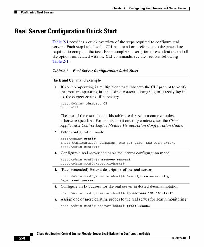
Real Server Configuration Quick StartTable 2-1 provides a quick overview of the steps required to configure real servers. Each step includes the CLI command or a reference to the procedure required to complete the task. For a complete description of each feature and all the options associated with the CLI commands, see the sections following Table 2-1.
Table 2-1 Real Server Configuration Quick Start
Task and Command Example
1. If you are operating in multiple contexts, observe the CLI prompt to verify that you are operating in the desired context. Change to, or directly log in to, the correct context if necessary.
host1/Admin# changeto C1host1/C1#
The rest of the examples in this table use the Admin context, unless otherwise specified. For details about creating contexts, see the Cisco Application Control Engine Module Virtualization Configuration Guide.
2. Enter configuration mode.
host/Admin# config Enter configuration commands, one per line. End with CNTL/Zhost1/Admin(config)#
3. Configure a real server and enter real server configuration mode.
host1/Admin(config)# rserver SERVER1host1/Admin(config-rserver-host)#
4. (Recommended) Enter a description of the real server.
host1/Admin(config-rserver-host)# description accounting department server
5. Configure an IP address for the real server in dotted-decimal notation.
host1/Admin(config-rserver-host)# ip address 192.168.12.15
6. Assign one or more existing probes to the real server for health monitoring.
host1/Admin(config-rserver-host)# probe PROBE1
2-4Cisco Application Control Engine Module Server Load-Balancing Configuration Guide
OL-9375-01

Chapter 2 Configuring Real Servers and Server FarmsConfiguring Real Servers
Creating a Real ServerYou can configure a real server and enter real server configuration mode by using the rserver command in configuration mode. You can create a maximum of 16,384 real servers. The syntax of this command is as follows:
rserver [host | redirect] name
The keywords, arguments, and options for this command are as follows:
• host—(Optional, default) Specifies a typical real server that provides content and services to clients.
• redirect—(Optional) Specifies a real server used to redirect traffic to a new location as specified in the relocn-string argument of the webhost-redirection command. See the “Configuring a Real Server Relocation String” section.
7. To prevent the real server from becoming overloaded, configure connection limits.
host1/Admin(config-rserver-host)# conn-limit max 20000000 min 15000000
8. If you plan to use the weighted round-robin or least connections predictor method, configure a weight for the real server.
host1/Admin(config-rserver-host)# weight 50
9. Place the real server in service.
host1/Admin(config-rserver-host)# inservicehost1/Admin(config-rserver-host)# Ctrl-Z
10. Use the following command to display the real server configuration. Make any modifications to your configuration as necessary, then reenter the command to verify your configuration changes.
host1/Admin# show running-config rserver
11. (Optional) Save your configuration changes to flash memory.
host1/Admin# copy running-config startup-config
Table 2-1 Real Server Configuration Quick Start (continued)
Task and Command Example
2-5Cisco Application Control Engine Module Server Load-Balancing Configuration Guide
OL-9375-01

Chapter 2 Configuring Real Servers and Server FarmsConfiguring Real Servers
• name—Identifier for the real server. Enter an unquoted text string with no spaces and maximum of 64 alphanumeric characters.
Note All servers in a server farm should be of the same type: host or redirect.
For example, to create a real server of type host, enter:
host1/Admin(config)# rserver server1host1/Admin(config-rserver-host)#
To remove the real server of type host from the configuration, enter:
host1/Admin(config)# no rserver server1
To create a real server of type redirect, enter:
host1/Admin(config)# rserver redirect server2host1/Admin(config-rserver-redirect)#
To remove the real server of type redirect from the configuration, enter:
host1/Admin(config)# no rserver redirect server2
The sections that follow apply to both real server types unless otherwise indicated.
Configuring a Real Server DescriptionYou can configure a description for a real server by using the description command in either real server host or real server redirect configuration mode. The syntax of this command is as follows:
description string
For the string argument, enter an unquoted alphanumeric text string with no spaces and a maximum of 240 characters.
For example, enter:
host1/Admin(config-rserver-host)# description accounting server
To remove the real-server description from the configuration, enter:
host1/Admin(config-rserver-host)# no description
2-6Cisco Application Control Engine Module Server Load-Balancing Configuration Guide
OL-9375-01
Chapter 2 Configuring Real Servers and Server FarmsConfiguring Real Servers
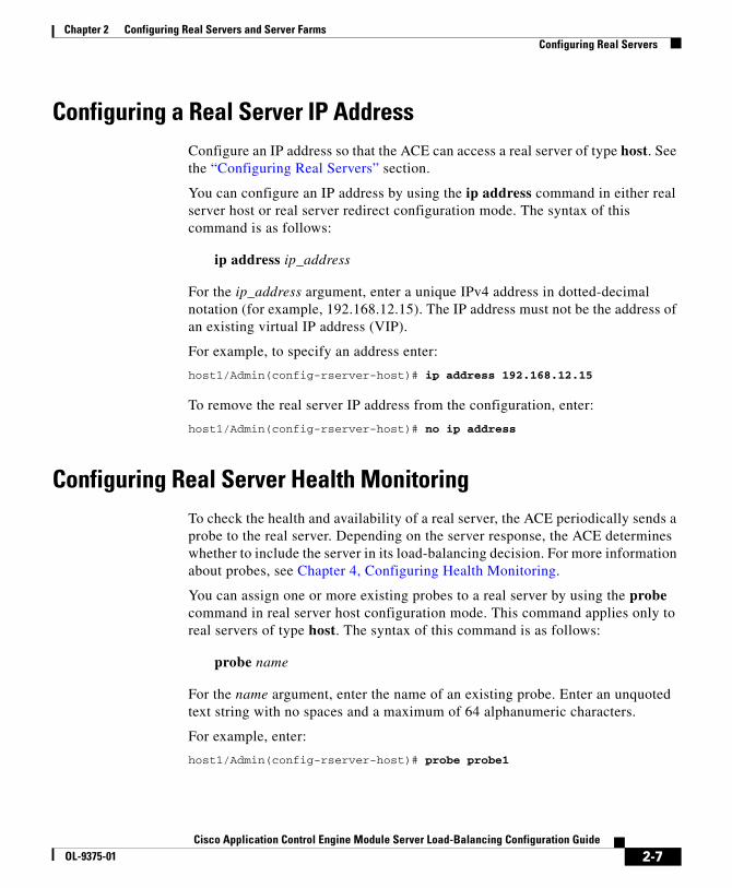
Configuring a Real Server IP AddressConfigure an IP address so that the ACE can access a real server of type host. See the “Configuring Real Servers” section.
You can configure an IP address by using the ip address command in either real server host or real server redirect configuration mode. The syntax of this command is as follows:
ip address ip_address
For the ip_address argument, enter a unique IPv4 address in dotted-decimal notation (for example, 192.168.12.15). The IP address must not be the address of an existing virtual IP address (VIP).
For example, to specify an address enter:
host1/Admin(config-rserver-host)# ip address 192.168.12.15
To remove the real server IP address from the configuration, enter:
host1/Admin(config-rserver-host)# no ip address
Configuring Real Server Health MonitoringTo check the health and availability of a real server, the ACE periodically sends a probe to the real server. Depending on the server response, the ACE determines whether to include the server in its load-balancing decision. For more information about probes, see Chapter 4, Configuring Health Monitoring.
You can assign one or more existing probes to a real server by using the probe command in real server host configuration mode. This command applies only to real servers of type host. The syntax of this command is as follows:
probe name
For the name argument, enter the name of an existing probe. Enter an unquoted text string with no spaces and a maximum of 64 alphanumeric characters.
For example, enter:
host1/Admin(config-rserver-host)# probe probe1
2-7Cisco Application Control Engine Module Server Load-Balancing Configuration Guide
OL-9375-01

Chapter 2 Configuring Real Servers and Server FarmsConfiguring Real Servers
To remove a real server probe from the configuration, enter:
host1/Admin(config-rserver-host)# no probe probe1
Configuring Real Server Connection LimitsTo prevent a real server from being overburdened, you can limit the maximum number of active connections to the server. You can set the maximum and minimum connection thresholds by using the conn-limit command in either real server host or real server redirect configuration mode. The syntax of this command is as follows:
conn-limit max maxconns min minconns
The keywords and arguments are as follows:
• max maxconns—Specifies the maximum allowable number of active connections to a real server. When the number of connections exceeds the maxconns threshold value, the ACE stops sending connections to the real server and assigns the real server a state of OUTOFSERVICE until the number of connections falls below the configured minconns value. Enter an integer from 2 to 4294967295. The default is 4294967295.
• min minconns—Specifies the minimum number of connections that the number of connections must fall below before sending more connections to a server after it has exceeded the maximum connections threshold. Enter an integer from 2 to 429496729. The default is 4294967295. The minconns value must be less than or equal to the maxconns value.
Because the ACE has two network processors (NPs), the maxconns value for a real server is divided between the two NPs. If you configure an odd value for maxconns, one of the NPs will have a maxconns value that is one greater than the value on the other NP. With very small values for maxconns, it is possible for a connection to be denied, even though one of the NPs has the capacity to handle the connection.
2-8Cisco Application Control Engine Module Server Load-Balancing Configuration Guide
OL-9375-01

Chapter 2 Configuring Real Servers and Server FarmsConfiguring Real Servers
Consider the scenario where you configure a value of 3 for the maxconns argument for a real server. One NP will have a value of 2 and the other NP will have a value of 1. If both NPs have reached their connection limits for that server, the next connection request for that server will be denied and the Out-of-rotation Count field of the show serverfarm detail command will increment by 1. Now, suppose a connection is closed on the NP with the maxconns value of 2. If the next connection request to the ACE goes to the NP with the maxconns value of 1 and it has already reached its limit, the ACE denies the connection, even though the other NP has the capacity to service the connection.
If you change the minconns value while there are live connections to a real server, the server could enter the MAXCONNS state without actually achieving the maxconns value in terms of the number of connections to it. Consider the following scenario where you configure a maxconns value of 10 and a minconns value of 5. Again, the ACE divides the values as equally as possible between the two NPs. In this case, both NPs would have a maxconns value of 5, while NP1 would have a minconns value of 3 and NP2 would have a minconns value of 2.
Suppose that the real server now has 10 live connections to it. Both NPs and the server have reached the MAXCONNS state. If four connections to the real server are closed leaving six live connections, both NPs (and, hence, the real server) would still be in the MAXCONNS state with three connections each. Remember, for an NP to come out of the MAXCONNS state, the number of connections to it must be less than the minconns value.
If you change the server’s minconns value to 7, NP1 would enter the OPERATIONAL state because the number of connections (three) is one less than the minconns value of 4. NP2 would still be in the MAXCONNS state (minconns value = number of connections = 3). NP1 could process two more connections for a total of only eight connections to the real server, which is two less than the server’s maxconns value of 10.
You can also specify minimum and maximum connections for a real server in a server farm configuration. The total of the minimum and maximum connections that you configure for a server in a server farm cannot exceed the minimum and maximum connections you set globally in real server configuration mode. For details about configuring real server maximum connections in a server farm configuration, see the “Configuring Connection Limits for a Real Server in a Server Farm” section.
For example, enter:
host1/Admin(config-rserver-host)# conn-limit max 5000 min 4000
2-9Cisco Application Control Engine Module Server Load-Balancing Configuration Guide
OL-9375-01
Chapter 2 Configuring Real Servers and Server FarmsConfiguring Real Servers
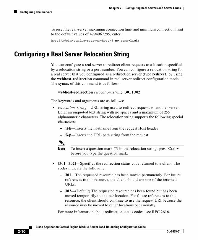
To reset the real-server maximum connection limit and minimum connection limit to the default values of 4294967295, enter:
host1/Admin(config-rserver-host)# no conn-limit
Configuring a Real Server Relocation StringYou can configure a real server to redirect client requests to a location specified by a relocation string or a port number. You can configure a relocation string for a real server that you configured as a redirection server (type redirect) by using the webhost-redirection command in real server redirect configuration mode. The syntax of this command is as follows:
webhost-redirection relocation_string [301 | 302]
The keywords and arguments are as follows:
• relocation_string—URL string used to redirect requests to another server. Enter an unquoted text string with no spaces and a maximum of 255 alphanumeric characters. The relocation string supports the following special characters:
– %h—Inserts the hostname from the request Host header
– %p—Inserts the URL path string from the request
Note To insert a question mark (?) in the relocation string, press Ctrl-v before you type the question mark.
• [301 | 302]—Specifies the redirection status code returned to a client. The codes indicate the following:
– 301—The requested resource has been moved permanently. For future references to this resource, the client should use one of the returned URLs.
– 302—(Default) The requested resource has been found but has been moved temporarily to another location. For future references to this resource, the client should continue to use the request URI because the resource may be moved to other locations occasionally.
For more information about redirection status codes, see RFC 2616.
2-10Cisco Application Control Engine Module Server Load-Balancing Configuration Guide
OL-9375-01

Chapter 2 Configuring Real Servers and Server FarmsConfiguring Real Servers
For example, enter:
host1/Admin(config-rserver-redir)# webhost-redirection http://%h/redirectbusy.cgi?path=%p 302
Assume the following client GET request:
GET /helloworld.html HTTP/1.1Host: www.cisco.com
The redirect response would appear as follows:
HTTP/1.1 302 FoundLocation: http://www.cisco.com/redirectbusy.cgi?path=/helloworld.html
To remove the relocation string from the configuration, enter:
host1/Admin(config-rserver-redir)# no webhost-redirection http://%h/redirectbusy.cgi?path=%p 302
Configuring a Real Server WeightYou can configure the connection capacity of a real server of type host in relation to the other servers in a server farm by using the weight command in real server host configuration mode. The ACE uses the weight value that you specify for a server in the weighted round-robin and least connections load-balancing predictors. Servers with a higher configured weight value have a higher priority with respect to connections than servers with a lower weight. For example, a server with a weight of 5 would receive five connections for every one connection for a server with a weight of 1.
Note Server weights take effect only when there are open connections to the servers. When there are no sustained connections to any of the servers, the leastconns predictor method behaves like the roundrobin method.
To specify different weight values for a real server of type host in a server farm, you can assign multiple IP addresses to the server. You can also use the same IP address of a real server with different port numbers.
The syntax of this command is as follows:
weight number
2-11Cisco Application Control Engine Module Server Load-Balancing Configuration Guide
OL-9375-01
Chapter 2 Configuring Real Servers and Server FarmsConfiguring Real Servers
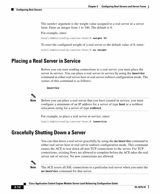
The number argument is the weight value assigned to a real server in a server farm. Enter an integer from 1 to 100. The default is 8.
For example, enter:
host1/Admin(config-rserver-host)# weight 50
To reset the configured weight of a real server to the default value of 8, enter:
host1/Admin(config-rserver-host)# no weight
Placing a Real Server in ServiceBefore you can start sending connections to a real server, you must place the server in service. You can place a real server in service by using the inservice command in either real server host or real server redirect configuration mode. The syntax of this command is as follows:
inservice
Note Before you can place a real server that you have created in service, you must configure a minimum of an IP address for a server of type host or a webhost relocation string for a server of type redirect.
For example, to place a real server in service, enter:
host1/Admin(config-rserver-host)# inservice
Gracefully Shutting Down a ServerYou can shut down a real server gracefully by using the no inservice command in either real server host or real server redirect configuration mode. This command causes the ACE to tear down all non-TCP connections to the server. For TCP connections, existing flows are allowed to complete before the ACE takes the real server out of service. No new connections are allowed.
Note The ACE resets all SSL connections to a particular real server when you enter the no inservice command for that server.
2-12Cisco Application Control Engine Module Server Load-Balancing Configuration Guide
OL-9375-01
Chapter 2 Configuring Real Servers and Server FarmsConfiguring a Server Farm
The syntax of this command is as follows:
no inservice
For example, to gracefully shut down a real server (for example, for maintenance or software upgrades), enter:
host1/Admin(config-rserver-host)# no inservice
Configuring a Server FarmThis section describes server farms and how to configure them. It contains the following topics:
• Server Farm Overview
• Server Farm Configuration Quick Start
• Creating a Server Farm
• Configuring a Description of a Server Farm
• Configuring the ACE Action on Server Failure
• Associating Multiple Health Probes with a Server Farm
• Configuring the Server Farm Predictor Method
• Configuring Server Farm HTTP Return Code Checking
• Associating a Real Server with a Server Farm
• Configuring a Backup Server Farm
• Specifying No NAT
Server Farm OverviewServer farms are groups of networked real servers that contain the same content and that typically reside in the same physical location in a data center. Web sites often comprise groups of servers configured in a server farm. Load-balancing software distributes client requests for content or services among the real servers based on the configured policy and traffic classification, server availability and load, and other factors. If one server goes down, another server can take its place and continue to provide the same content to the clients who requested it.
2-13Cisco Application Control Engine Module Server Load-Balancing Configuration Guide
OL-9375-01
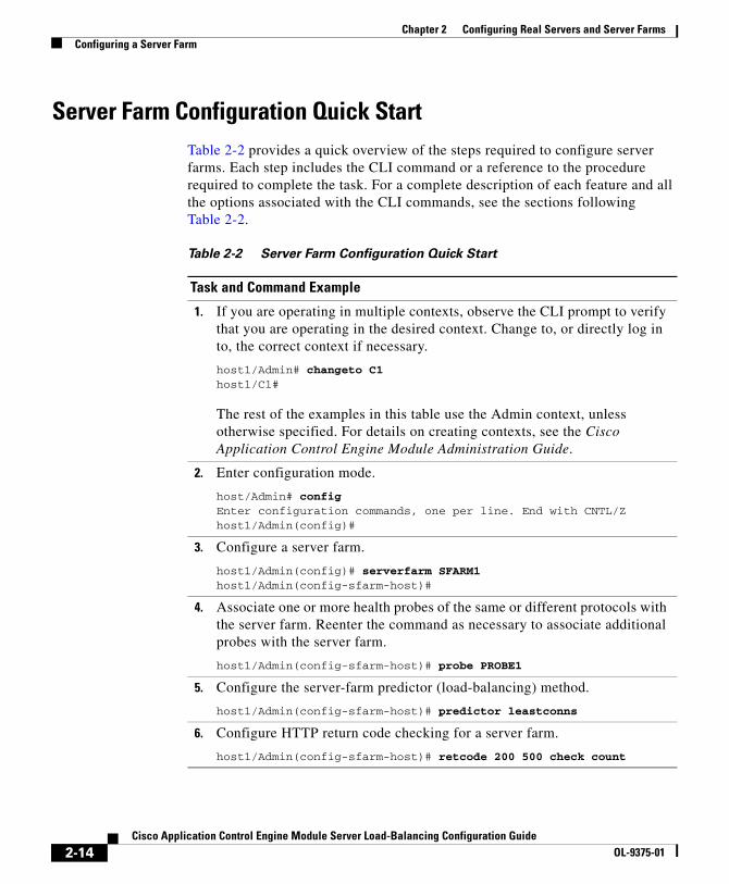
Chapter 2 Configuring Real Servers and Server FarmsConfiguring a Server Farm
Server Farm Configuration Quick StartTable 2-2 provides a quick overview of the steps required to configure server farms. Each step includes the CLI command or a reference to the procedure required to complete the task. For a complete description of each feature and all the options associated with the CLI commands, see the sections following Table 2-2.
Table 2-2 Server Farm Configuration Quick Start
Task and Command Example
1. If you are operating in multiple contexts, observe the CLI prompt to verify that you are operating in the desired context. Change to, or directly log in to, the correct context if necessary.
host1/Admin# changeto C1host1/C1#
The rest of the examples in this table use the Admin context, unless otherwise specified. For details on creating contexts, see the Cisco Application Control Engine Module Administration Guide.
2. Enter configuration mode.
host/Admin# config Enter configuration commands, one per line. End with CNTL/Zhost1/Admin(config)#
3. Configure a server farm.
host1/Admin(config)# serverfarm SFARM1host1/Admin(config-sfarm-host)#
4. Associate one or more health probes of the same or different protocols with the server farm. Reenter the command as necessary to associate additional probes with the server farm.
host1/Admin(config-sfarm-host)# probe PROBE1
5. Configure the server-farm predictor (load-balancing) method.
host1/Admin(config-sfarm-host)# predictor leastconns
6. Configure HTTP return code checking for a server farm.
host1/Admin(config-sfarm-host)# retcode 200 500 check count
2-14Cisco Application Control Engine Module Server Load-Balancing Configuration Guide
OL-9375-01
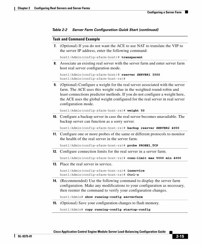
Chapter 2 Configuring Real Servers and Server FarmsConfiguring a Server Farm
7. (Optional) If you do not want the ACE to use NAT to translate the VIP to the server IP address, enter the following command:
host1/Admin(config-sfarm-host)# transparent
8. Associate an existing real server with the server farm and enter server farm host real server configuration mode.
host1/Admin(config-sfarm-host)# rserver SERVER1 3000host1/Admin(config-sfarm-host-rs)#
9. (Optional) Configure a weight for the real server associated with the server farm. The ACE uses this weight value in the weighted round-robin and least-connections predictor methods. If you do not configure a weight here, the ACE uses the global weight configured for the real server in real server configuration mode.
host1/Admin(config-sfarm-host-rs)# weight 50
10. Configure a backup server in case the real server becomes unavailable. The backup server can function as a sorry server.
host1/Admin(config-sfarm-host-rs)# backup rserver SERVER2 4000
11. Configure one or more probes of the same or different protocols to monitor the health of the real server in the server farm.
host1/Admin(config-sfarm-host-rs)# probe PROBE1_TCP
12. Configure connection limits for the real server in a server farm.
host1/Admin(config-sfarm-host-rs)# conn-limit max 5000 min 4000
13. Place the real server in service.
host1/Admin(config-sfarm-host-rs)# inservicehost1/Admin(config-sfarm-host-rs)# Ctrl-z
14. (Recommended) Use the following command to display the server farm configuration. Make any modifications to your configuration as necessary, then reenter the command to verify your configuration changes.
host1/Admin# show running-config serverfarm
15. (Optional) Save your configuration changes to flash memory.
host1/Admin# copy running-config startup-config
Table 2-2 Server Farm Configuration Quick Start (continued)
Task and Command Example
2-15Cisco Application Control Engine Module Server Load-Balancing Configuration Guide
OL-9375-01
Chapter 2 Configuring Real Servers and Server FarmsConfiguring a Server Farm
Creating a Server FarmYou can create a new server farm or modify an existing server farm and enter the server-farm configuration mode by using the serverfarm command in configuration mode. You can configure a maximum of 16,384 server farms on each ACE.
The syntax of this command is as follows:
serverfarm [host | redirect] name
The keywords, arguments, and options are as follows:
• host—(Optional, default) Specifies a typical server farm that consists of real servers that provide content and services to clients and accesses server farm host configuration mode.
• redirect—(Optional) Specifies that the server farm consists only of real servers that redirect client requests to alternate locations specified by the relocation string or port number in the real server configuration and accesses server farm redirect configuration mode. See the “Configuring a Real Server Relocation String” section.
• name—Unique identifier of the server farm. Enter an unquoted text string with no spaces and a maximum of 64 alphanumeric characters.
For example, to create a server farm of type host called SFARM1, enter:
host1/Admin(config)# serverfarm SFARM1host1/Admin(config-sfarm-host)#
For example, to create a server farm of type redirect called SFARM2, enter:
host1/Admin(config)# serverfarm redirect SFARM2host1/Admin(config-sfarm-redirect)#
After you create a server farm, you can configure the other server farm attributes and add real servers to it as described in the following sections:
• Configuring the ACE Action on Server Failure
• Associating Multiple Health Probes with a Server Farm
• Configuring the Server Farm Predictor Method
• Configuring Server Farm HTTP Return Code Checking
2-16Cisco Application Control Engine Module Server Load-Balancing Configuration Guide
OL-9375-01
Chapter 2 Configuring Real Servers and Server FarmsConfiguring a Server Farm
• Associating a Real Server with a Server Farm
• Specifying No NAT
Configuring a Description of a Server FarmYou can provide a text description of a server farm by using the description command in either server farm host or server farm redirect configuration mode. The syntax of this command is as follows:
description text
For the text argument, enter a server farm description with a maximum of 240 alphanumeric characters.
For example, to enter a description of a server farm, enter:
host1/Admin(config-sfarm-host)# description CURRENT EVENTS ARCHIVE
To remove the description of a server farm, enter:
host1/Admin(config-sfarm-host)# no description
Configuring the ACE Action on Server FailureYou can set the action that the ACE takes with respect to connections if any real server fails in a server farm. You can configure the failure action by using the failaction command in either server farm host or server farm redirect configuration mode. The syntax of this command is as follows:
failaction purge
The purge keyword specifies that the ACE remove the connections to a real server if that real server in the server farm fails after you enter the command. The ACE sends a reset (RST) to both the client and the server that failed.
Note If you do not configure this command, the ACE takes no action when a server fails. To clear connections to servers that have failed prior to entering the failaction command, use the clear conn command. For details about the clear conn command, see the “Clearing Real Server Connections” section.
2-17Cisco Application Control Engine Module Server Load-Balancing Configuration Guide
OL-9375-01
Chapter 2 Configuring Real Servers and Server FarmsConfiguring a Server Farm
For example, to remove connections from a failed server in the server farm, enter:
host1/Admin(config-sfarm-host)# failaction purge
To reset the behavior of the ACE to the default of taking no action if a real server fails, enter:
host1/Admin(config-sfarm-host)# no failaction
Associating Multiple Health Probes with a Server FarmYou can associate multiple health probes of the same or different protocols with each server farm. Each server farm supports the following probe types:
• DNS
• ECHO (TCP and UDP)
• Finger
• FTP
• HTTP
• HTTPS
• ICMP
• IMAP
• LDAP
• POP/POP3
• RADIUS
• Scripted
• SMTP
• TCP
• Telnet
• UDP
You can associate a probe with a server farm by using the probe command in server farm host configuration mode only. The syntax of this command is as follows:
probe name
2-18Cisco Application Control Engine Module Server Load-Balancing Configuration Guide
OL-9375-01
Chapter 2 Configuring Real Servers and Server FarmsConfiguring a Server Farm
For the name argument, enter the name of an existing probe as a text string with no spaces and a maximum of 64 alphanumeric characters. For information about configuring probes, see Chapter 4, Configuring Health Monitoring.
For example, enter:
host1/Admin(config-sfarm-host)# probe PROBE1
To remove the probe from the server farm configuration, enter:
host1/Admin(config-sfarm-host)# no probe PROBE1
Configuring the Server Farm Predictor MethodThe load-balancing (predictor) method that you configure determines how the ACE selects a real server in a server farm to service a client request. You can configure the load-balancing method by using the predictor command in either server farm host or server farm redirect configuration mode. The syntax of this command is as follows:
predictor {roundrobin | leastconns [slowstart time] | hash {address [destination | source] [netmask] | cookie name1 | header name2 | url [begin-pattern text] [end-pattern text]}}
Note You can associate a maximum of 1024 instances of the same type of regex with each Layer 3 and Layer 4 policy map. This limit applies to all Layer 7 policy-map types, including generic, HTTP, RADIUS, RDP, RTSP, and SIP. You configure regexes in:
• Match statements in Layer 7 class maps
• Inline match statements in Layer 7 policy maps
• Layer 7 hash predictors for server farms
• Layer 7 sticky expressions in sticky groups
• Header insertion and rewrite (including SSL URL rewrite) expressions in Layer 7 action lists
2-19Cisco Application Control Engine Module Server Load-Balancing Configuration Guide
OL-9375-01
Chapter 2 Configuring Real Servers and Server FarmsConfiguring a Server Farm
Note The hash predictor methods do not recognize the weight value you configure for real servers. The ACE uses the weight that you assign to real servers only in the round-robin and least-connections predictor methods.
The keywords and arguments are as follows:
• roundrobin—(Default) Selects the next server in the list of real servers based on server weight (weighted round-robin). For information about setting server weight, see the “Configuring a Real Server Weight” section and the “Configuring the Weight of a Real Server in a Server Farm” section.
• leastconns—Selects the server with the fewest number of connections based on server weight. Use this predictor for processing light user requests (for example, browsing simple static web pages). For information about setting server weight, see the “Configuring a Real Server Weight” section and the “Configuring the Weight of a Real Server in a Server Farm” section.
Note Server weights take effect only when there are open connections to the servers. When there are no sustained connections to any of the servers, the leastconns predictor method behaves like the roundrobin method.
The optional slowstart time keyword and argument specify that the connections to the real server be in a slow-start mode. The ACE calculates a slow-start time stamp from the current time plus the time value that you specify. The ACE uses the timestamp as a fail-safe mechanism in case a real server stays in slow-start mode for a prolonged period of time (for example, with long-lived flows). Enter an integer from 1 to 65535 seconds. By default, slowstart is disabled.
Use the slow-start mechanism to avoid sending a high rate of new connections to servers that you have recently put into service. When a new real server enters slow-start mode, the ACE calculates and assigns an artificially high metric weight value to the new server and sends a small number of connections to the new server initially. The remaining connections go to the existing servers based on their weight and current connections.
2-20Cisco Application Control Engine Module Server Load-Balancing Configuration Guide
OL-9375-01

Chapter 2 Configuring Real Servers and Server FarmsConfiguring a Server Farm
The real server (including the new server) with the lowest calculation (weight × current connections) receives the next connection request for the server farm. Each time that the ACE assigns a new connection to the new real server, the ACE checks the validity of the timestamp. If the timestamp has expired, the ACE takes the server out of slow-start mode. As the new server connections are finished (closed), the ACE decrements both the new server connection count and the metric weight value by the number of closed connections.
A real server exits slow-start mode when one of the following events occurs:
• Slow-start timestamp expires
• New real server metric weight reaches a value of 0
Note It is possible for a new real server to remain in slow-start mode for a period that is longer than the time value you configure. This may happen because the ACE checks the timestamp only when it assigns a new connection to the real server.
The ACE places real servers in slow-start mode only if they have no existing connections to them. For example, if you have two real servers (RSERVER1 and RSERVER2) in a server farm that have the same number of active connections to them, slow start is configured for 180 seconds, and you add a new real server (RSERVER3) to the server farm, the ACE places the new real server in slow-start mode and sends a small number of new connections to it. The ACE equally divides the remainder of the new connections between RSERVER1 and RSERVER2. At this point, if RSERVER1 goes into any failed state (for example, PROBE-FAILED or ARP-FAILED) and then later it is placed back in service within 180 seconds of RSERVER3's addition to the server farm, the ACE does not put RSERVER1 in slow-start mode because of the connections to RSERVER1 that existed before the out-of-service event.
Instead, the ACE sends most or all of the new connections to RSERVER1 in an effort to make the connection count the same as RSERVER2 and ignores RSERVER3, which is still in slow-start mode. When the connection count for RSERVER1 and RSERVER2 are similar, then the ACE resumes sending a small number of connections to RSERVER3 for the duration of the slow-start timer.
2-21Cisco Application Control Engine Module Server Load-Balancing Configuration Guide
OL-9375-01
Chapter 2 Configuring Real Servers and Server FarmsConfiguring a Server Farm
If RSERVER1 returns to the OPERATIONAL state more than 180 seconds after you added RSERVER3 to the server farm, then RSERVER3 will be out of slow-start mode. In this case, the ACE sends most or all of the new connections to RSERVER1 in an effort to make the connection count the same as RSERVER2 or RSERVER3, whichever has the least number of connections.
To ensure that a failed server with existing connections enters slow-start mode when it is placed back in service, configure failaction purge for the real server in a server farm. This command removes all existing connections to the real server if it fails. For details about the failaction purge command, see the “Configuring the ACE Action on Server Failure” section.
• hash address—Selects the server using a hash value based on the source and destination IP addresses. Use the hash address source and hash address destination methods for firewall load balancing (FWLB). For more information about FWLB, see Chapter 6, Configuring Firewall Load Balancing.
– source—(Optional) Selects the server using a hash value based on the source IP address.
– destination—(Optional) Selects the server using a hash value based on the destination IP address.
– netmask—(Optional) Bits in the IP address to use for the hash. If not specified, the default is 255.255.255.255.
• hash cookie name1—Selects the server using a hash value based on the cookie name. Enter a cookie name as an unquoted text string with no spaces and a maximum of 64 alphanumeric characters.
• hash header name2—Selects the server using a hash value based on the header name. Enter a header name as an unquoted text string with no spaces and a maximum of 64 alphanumeric characters or enter one of the following standard headers:
– Accept
– Accept-Charset
– Accept-Encoding
– Accept-Language
– Authorization
– Cache-Control
2-22Cisco Application Control Engine Module Server Load-Balancing Configuration Guide
OL-9375-01
Chapter 2 Configuring Real Servers and Server FarmsConfiguring a Server Farm
– Connection
– Content-MD5
– Expect
– From
– Host
– If-Match
– Pragma
– Referrer
– Transfer-Encoding
– User-Agent
– Via
• hash url—Selects the server using a hash value based on the requested URL. Use this predictor method to load balance cache servers. Cache servers perform better with the URL hash method because you can divide the contents of the caches evenly if the traffic is random enough. In a redundant configuration, the cache servers continue to work even if the active ACE switches over to the standby ACE. For information about configuring redundancy, see the Cisco Application Control Engine Module Administration Guide.
– begin-pattern text—Specifies the beginning pattern of the URL and the pattern string to parse. You cannot configure different beginning and ending patterns for different server farms that are part of the same traffic classification. (See Chapter 3, Configuring Traffic Policies for Server Load Balancing.) Enter an unquoted text string with no spaces and a maximum of 255 alphanumeric characters for each pattern you configure. If you want to match a URL that contains spaces, you must use “\x20” (without the quotation marks) for each space character.
– end-pattern text—Specifies the ending pattern of the URL and the pattern string to parse. You cannot configure different beginning and ending patterns for different server farms that are part of the same traffic classification. (See Chapter 3, Configuring Traffic Policies for Server Load Balancing.) Enter an unquoted text string with no spaces and a maximum of 255 alphanumeric characters for each pattern you configure. If you want to match a URL that contains spaces, you must use “\x20” (without the quotation marks) for each space character.
2-23Cisco Application Control Engine Module Server Load-Balancing Configuration Guide
OL-9375-01

Chapter 2 Configuring Real Servers and Server FarmsConfiguring a Server Farm
For example, to select the server with the lowest number of connections in the server farm, enter:
host1/Admin(config-sfarm-host)# predictor leastconns
To reset the predictor algorithm to the default of roundrobin, enter:
host1/Admin(config-sfarm-host)# no predictor
Configuring Server Farm HTTP Return Code CheckingYou can configure HTTP return-code checking (retcode map) for a server farm by using the retcode command in server farm host configuration mode only. You can specify a single return code number or a range of return code numbers. For example, you can instruct the ACE to check for and count the number of occurrences of such return codes as HTTP/1.1 200 OK, HTTP/1.1 100 Continue, or HTTP/1.1 404 Not Found.
The syntax of this command is as follows:
retcode number1 number2 check count
The keywords, arguments, and options are as follows:
• number1—Minimum value for an HTTP return code. Enter an integer from 100 to 599. The minimum value must be less than or equal to the maximum value.
• number2—Maximum value for an HTTP return code. Enter an integer from 100 to 599. The maximum value must be greater than or equal to the minimum value.
• check—Checks for HTTP return codes associated with the server farm.
• count—Tracks the total number of return codes received for each return code number that you specify.
You can configure multiple retcode maps on each server farm. You can view hit counts for retcode checking by using the show serverfarm command. For details, see the “Displaying Server Farm Statistics” section.
For example, to check for and count the number of return code hits for all return codes from 200 to 500 inclusive, enter:
host1/Admin(config-sfarm-host)# retcode 200 500 check count
2-24Cisco Application Control Engine Module Server Load-Balancing Configuration Guide
OL-9375-01
Chapter 2 Configuring Real Servers and Server FarmsConfiguring a Server Farm
To remove the HTTP return-code map from the configuration, enter:
host1/Admin(config-sfarm-host)# no retcode 200 500 check count
Associating a Real Server with a Server FarmYou can associate one or more real servers with a server farm and enter real-server server-farm configuration mode by using the rserver command in either server farm host or server farm redirect configuration mode. The real server must already exist. For information about configuring a real server, see the “Configuring Real Servers” section. You can configure a maximum of 16,384 real servers in a server farm. The syntax of this command is as follows:
rserver name [port]
The arguments are as follows:
• name—Unique identifier of an existing real server. Enter an unquoted text string with no spaces and a maximum of 64 alphanumeric characters.
• port—(Optional) Port number used for the real server port address translation (PAT). Enter an integer from 1 to 65535.
If you choose not to assign a port number for the real server association with the server farm, the default behavior by the ACE is to automatically assign the same destination port that was used by the inbound connection to the outbound server connection. For example, if the incoming connection to the ACE is a secure client HTTPS connection, the connection is typically made on port 443. If you do not assign a port number to the real server, the ACE will automatically use port 443 to connect to the server, which results in the ACE making a clear-text HTTP connection over port 443. In this case, you would typically define an outbound destination port of 80, 81, or 8080 for the back-end server connection.
For example, to identify real server SERVER1 and specify port 80 for the outgoing connection, enter:
host1/Admin(config-sfarm-host)# rserver SERVER1 80host1/Admin(config-sfarm-host-rs)#
To remove the real server association with the server farm, enter:
host1/Admin(config-sfarm-host)# no rserver SERVER1 80
2-25Cisco Application Control Engine Module Server Load-Balancing Configuration Guide
OL-9375-01
Chapter 2 Configuring Real Servers and Server FarmsConfiguring a Server Farm
After you have associated a real server with a server farm, you can configure other real server attributes as described in the following topics:
• Configuring the Weight of a Real Server in a Server Farm
• Configuring a Backup Server for a Real Server
• Configuring Health Monitoring for a Server Farm
• Configuring Connection Limits for a Real Server in a Server Farm
• Placing a Real Server in Service
• Gracefully Shutting Down a Server with Sticky Connections
Configuring the Weight of a Real Server in a Server Farm
The ACE uses a real server weight value with the weighted round-robin and least connections predictor methods. Servers with higher weight values receive a proportionally higher number of connections than servers with lower weight values. If you do not specify a weight in real configuration mode under a server farm, the ACE uses the weight you configured for the global real server in real server configuration mode. See the “Configuring a Real Server Weight” section.
Note Server weights take effect only when there are open connections to the servers. When there are no sustained connections to any of the servers, the leastconns predictor method behaves like the roundrobin method.
You can configure the weight of a real server in a server farm by using the weight command in server farm host real server configuration mode. The syntax of this command is as follows:
weight number
The number argument is the weight value assigned to a real server in a server farm. Enter an integer from 0 to 100. The default is 8.
For example, enter:
host1/Admin(config-sfarm-host-rs)# weight 50
To reset the configured weight of a real server to the default of 8, enter:
host1/Admin(config-sfarm-host-rs)# no weight
2-26Cisco Application Control Engine Module Server Load-Balancing Configuration Guide
OL-9375-01
Chapter 2 Configuring Real Servers and Server FarmsConfiguring a Server Farm
Configuring a Backup Server for a Real Server
You can designate an existing real server as a backup server for another real server in case that server becomes unavailable. A backup server is sometimes referred to as a sorry server. If the real server becomes unavailable, the ACE automatically redirects client requests to the backup server. You can configure a backup server by using the backup-rserver command in server farm host real server configuration mode.
Note If you are configuring a backup server for a real server, be sure to specify the optional standby key word when you place the backup server in service. For details, see the “Placing a Real Server in Service” section.
The syntax of this command is as follows:
backup-rserver name [port]
The keywords and arguments are as follows:
• name—Name of an existing real server that you want to configure as a backup server. Enter an unquoted text string with no spaces and a maximum of 64 alphanumeric characters.
• port—(Optional) Port number used for the backup real server port address translation (PAT). Enter an integer from 0 to 65535.
For example, enter:
host1/Admin(config-sfarm-host-rs)# backup-rserver SERVER1 4000
To remove the backup server from the configuration, enter:
host1/Admin(config-sfarm-host-rs)# no backup-rserver
Configuring Health Monitoring for a Server Farm
You can monitor the health of the real servers in a server farm by configuring one or more health probes (sometimes called keepalives) for the server farm. You can associate multiple probes of the same or different protocols with a server farm. Once you configure the probes, the ACE periodically sends the probes to the real servers. If the ACE receives the appropriate responses from the servers, the ACE includes the servers in load-balancing decisions. If not, the ACE marks the servers as out of service, depending on the configured number of retries.
2-27Cisco Application Control Engine Module Server Load-Balancing Configuration Guide
OL-9375-01

Chapter 2 Configuring Real Servers and Server FarmsConfiguring a Server Farm
You can associate a health probe with a server farm by using the probe command in server farm host real server configuration mode. The syntax of this command is as follows:
probe probe_name
For the probe_name argument, enter the name of an existing probe as an unquoted text string with no spaces and a maximum of 64 alphanumeric characters.
For example, enter:
host1/Admin(config-sfarm-host-rs)# probe PROBE1_TCP
To remove the real server health probe from the configuration, enter:
host1/Admin(config-sfarm-host-rs)# no probe PROBE1_TCP
Configuring Connection Limits for a Real Server in a Server Farm
You can prevent a real server from becoming overloaded by limiting the number of connections allowed to that server. You can limit the number of connections to a real server by using the conn-limit command in server-farm real server configuration mode. The syntax of this command is as follows:
conn-limit max maxconns min minconns
The keywords and arguments are as follows:
• max maxconns—Specifies the maximum number of active connections to a real server. When the number of connections exceeds the maxconns threshold value, the ACE stops sending connections to the real server until the number of connections falls below the configured minconns value. Enter an integer from 2 to 4294967295. The default is 4294967295.
• min minconns—Specifies the minimum number of connections that the number of connections must fall below before sending more connections to a server after it has exceeded the maxconns threshold. The minconns value must be less than or equal to the maxconns value. The default is 4294967295.
Because the ACE has two network processors (NPs), the maxconns value for a real server is divided between the two NPs. If you configure an odd value for maxconns, one of the NPs will have a maxconns value that is one greater than the value on the other NP. With very small values for maxconns, it is possible for a connection to be denied, even though one of the NPs has the capacity to handle the connection.
2-28Cisco Application Control Engine Module Server Load-Balancing Configuration Guide
OL-9375-01

Chapter 2 Configuring Real Servers and Server FarmsConfiguring a Server Farm
Consider the scenario where you configure a value of 3 for the maxconns argument for a real server. One NP will have a value of 2 and the other NP will have a value of 1. If both NPs have reached their connection limits for that server, the next connection request for that server will be denied and the Out-of-rotation Count field of the show serverfarm detail command will increment by 1. Now, suppose a connection is closed on the NP with the maxconns value of 2. If the next connection request to the ACE goes to the NP with the maxconns value of 1 and it has already reached its limit, the ACE denies the connection, even though the other NP has the capacity to service the connection.
For example, enter:
host1/Admin(config-sfarm-host-rs)# conn-limit max 5000 min 4000
To remove the connection limit from a real server, enter:
host1/Admin(config-sfarm-host-rs)# no conn-limit
Placing a Real Server in Service
Before you can start sending connections to a real server in a server farm, you must place it in service. You can place a real server in a server farm in service by using the inservice command in either server farm host real server or server farm redirect real server configuration mode.
The syntax of this command is as follows:
inservice [standby]
Use the optional standby keyword when you are configuring backup real servers. The standby keyword specifies that a backup real server remain inactive unless the primary real server fails. If the primary fails, the backup server becomes active and starts accepting connections.
Note You can modify the configuration of a real server in a server farm without taking the server out of service.
For example, enter:
host1/Admin(config-sfarm-host-rs)# inservice standby
2-29Cisco Application Control Engine Module Server Load-Balancing Configuration Guide
OL-9375-01

Chapter 2 Configuring Real Servers and Server FarmsConfiguring a Server Farm
To take a backup real server out of service for maintenance or software upgrades, enter:
host1/Admin(config-sfarm-host-rs)# no inservice standby
Gracefully Shutting Down a Server with Sticky Connections
In addition to putting a backup real server in service standby, another use of the inservice standby command is to provide a graceful shutdown of primary real servers. Use this command to gracefully shut down servers with sticky connections. When you enter this command for a primary real server, the ACE does the following:
• Tears down existing non-TCP connections to the server
• Allows current TCP connections to complete
• Allows new sticky connections for existing server connections that match entries in the sticky database
• Load balances all new connections (other than the matching sticky connections mentioned above) to the other servers in the server farm
• Eventually takes the server out of service
For example, to perform a graceful shutdown on a primary real server with sticky connections in a server farm, enter:
host1/Admin(config)# serverfarm sf1host1/Admin(config-sfarm-host)# rserver rs1host1/Admin(config-sfarm-host-rs)# inservice standby
Configuring a Backup Server FarmConfigure a backup server farm to ensure that, if all the real servers in a server farm go down, the ACE continues to service client requests. You configure a backup server farm as an action in a Layer 7 policy map under a Layer 7 class map using the serverfarm name1 [backup name2 [sticky] [aggregate-state]] command. For details about configuring a backup server farm, see the “Enabling Load Balancing to a Server Farm (Configuring a Backup Server)” section in Chapter 3, Configuring Traffic Policies for Server Load Balancing.
2-30Cisco Application Control Engine Module Server Load-Balancing Configuration Guide
OL-9375-01

Chapter 2 Configuring Real Servers and Server FarmsDisplaying Real Server Configurations and Statistics
Specifying No NATYou can instruct the ACE not to use NAT to translate the VIP address to the server IP address by using the transparent command in serverfarm host configuration mode. Use this command in firewall load balancing (FWLB) when you configure the insecure and secure sides of the firewall as a server farm. For details about FWLB, see Chapter 6, Configuring Firewall Load Balancing. The syntax of this command is as follows:
transparent
For example, enter:
host1/Admin(config-sfarm-host)# transparent
Displaying Real Server Configurations and StatisticsThis section describes the commands that you can use to display information about the real-server configuration and statistics. It contains the following topics:
• Displaying Real Server Configurations
• Displaying Real Server Statistics
• Displaying Real Server Connections
Displaying Real Server ConfigurationsYou can display information about the real-server configuration by using the show running-config rserver command in Exec mode. The syntax of this command is as follows:
show running-config rserver
2-31Cisco Application Control Engine Module Server Load-Balancing Configuration Guide
OL-9375-01

Chapter 2 Configuring Real Servers and Server FarmsDisplaying Real Server Configurations and Statistics
Displaying Real Server StatisticsYou can display summary or detailed statistics for a named real server or for all real servers by using the show rserver command in Exec mode. The syntax of this command is as follows:
show rserver [name] [detail]
The argument and option are as follows:
• name—(Optional) Identifier of an existing real server. Enter an unquoted text string with no spaces and a maximum of 64 alphanumeric characters.
• detail—(Optional) Displays detailed statistics for the real server name that you enter or for all real servers.
For example, to display detailed statistics for all configured real servers, enter:
host1/Admin# show rserver detail
Table 2-3 describes the fields in the show rserver command output.
Table 2-3 Field Descriptions for the show rserver Command Output
Field Description
Summary Real Server Information
Rserver Name of the real server.
Type Type of configured real server: HOST or REDIRECT.
State Current state of the real server: INACTIVE (not associated with a server farm), OPERATIONAL, or OUTOFSERVICE.
Real
Serverfarm Name of the server farm to which the server belongs.
IP Address IP address of the real server.
Weight Weight of the real server in the server farm.
State State of the server farm: OPERATIONAL or OUTOFSERVICE.
Current Connections
Number of active connections to the real server.
2-32Cisco Application Control Engine Module Server Load-Balancing Configuration Guide
OL-9375-01
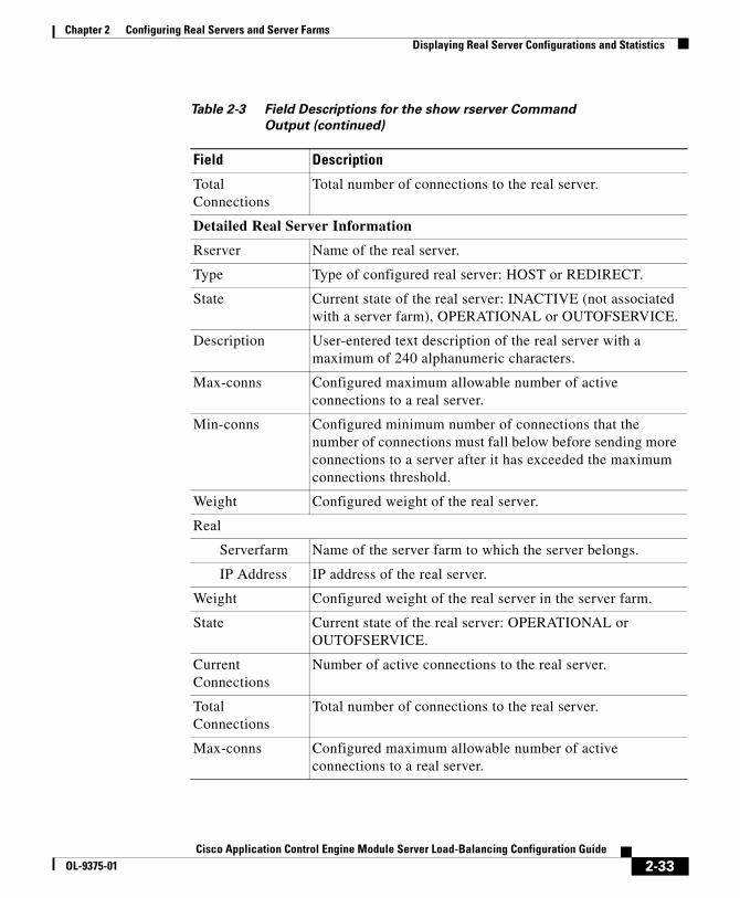
Chapter 2 Configuring Real Servers and Server FarmsDisplaying Real Server Configurations and Statistics
Total Connections
Total number of connections to the real server.
Detailed Real Server Information
Rserver Name of the real server.
Type Type of configured real server: HOST or REDIRECT.
State Current state of the real server: INACTIVE (not associated with a server farm), OPERATIONAL or OUTOFSERVICE.
Description User-entered text description of the real server with a maximum of 240 alphanumeric characters.
Max-conns Configured maximum allowable number of active connections to a real server.
Min-conns Configured minimum number of connections that the number of connections must fall below before sending more connections to a server after it has exceeded the maximum connections threshold.
Weight Configured weight of the real server.
Real
Serverfarm Name of the server farm to which the server belongs.
IP Address IP address of the real server.
Weight Configured weight of the real server in the server farm.
State Current state of the real server: OPERATIONAL or OUTOFSERVICE.
Current Connections
Number of active connections to the real server.
Total Connections
Total number of connections to the real server.
Max-conns Configured maximum allowable number of active connections to a real server.
Table 2-3 Field Descriptions for the show rserver Command Output (continued)
Field Description
2-33Cisco Application Control Engine Module Server Load-Balancing Configuration Guide
OL-9375-01

Chapter 2 Configuring Real Servers and Server FarmsDisplaying Real Server Configurations and Statistics
Displaying Real Server ConnectionsYou can display active inbound and outbound real server connections by using the show conn rserver command in Exec mode. The syntax of this command is as follows:
show conn rserver name1 [port_number] [name2]
The arguments of this command are as follows:
• name1—Identifier of an existing real server whose connections you want to display. Enter an unquoted text string with no spaces and a maximum of 64 alphanumeric characters.
• port_number—(Optional) Port number of the server. Enter an integer from 1 to 65535.
• name2—(Optional) Identifier of an existing server farm with which the real server is associated. Enter an unquoted text string with no spaces and a maximum of 64 alphanumeric characters.
For example, enter:
host1/Admin# show conn rserver SERVER1 4000 serverfarm SFARM1
Min-conns Configured minimum number of connections that the number of connections must fall below before sending more connections to a server after it has exceeded the maximum connections threshold.
Total Conn-failures
Total number of connection attempts that failed to establish a connection to the real server.
Table 2-3 Field Descriptions for the show rserver Command Output (continued)
Field Description
2-34Cisco Application Control Engine Module Server Load-Balancing Configuration Guide
OL-9375-01

Chapter 2 Configuring Real Servers and Server FarmsDisplaying Real Server Configurations and Statistics
Table 2-4 describes the fields in the show conn rserver command output.
Table 2-4 Field Descriptions for the show conn rserver Command Output
Field Description
Conn-ID Numerical identifier of the connection.
Dir Direction of the traffic on the connection: in or out.
Prot TCP/IP protocol used in the connection.
VLAN Numerical identifier of the virtual LANs used in the inbound and the outbound connections.
Source Source IP addresses and ports of the inbound and outbound connections.
Destination Destination IP addresses and ports of the inbound and outbound connections.
State Current state of the connection. Non-TCP connections display as “--”. Possible values for TCP connections are as follows:
• INIT—Connection is closed. This is the initial state of a connection.
• SYNSEEN—ACE received a SYN packet from a client
• SYNACK—ACE sent a SYNACK packet to a client
• ESTAB—Three-way handshake completed and the connection is established
• CLSFIN—ACE closed the connection with a FIN packet
• CLSRST—ACE closed the connection by resetting it
• CLSTIMEOUT—ACE closed the connection because the connection timed out
• CLOSED—Connection is half closed
2-35Cisco Application Control Engine Module Server Load-Balancing Configuration Guide
OL-9375-01
Chapter 2 Configuring Real Servers and Server FarmsClearing Real Server Statistics and Connections
Clearing Real Server Statistics and ConnectionsThis section describes the commands you use to clear real server statistics and connection information. It contains the following topics:
• Clearing Real Server Statistics
• Clearing Real Server Connections
Clearing Real Server StatisticsYou can reset statistics to zero for all instances of a particular real server regardless of the server farms that it is associated with by using the clear rserver command in Exec mode. The syntax of this command is as follows:
clear rserver name
The name argument is the identifier of an existing real server whose statistics you want to clear. Enter a real server name as an unquoted text string with no spaces and a maximum of 64 alphanumeric characters.
For example, to reset the statistics of real server SERVER1, enter:
host1/Admin# clear rserver SERVER1
Note If you have redundancy configured, then you need to explicitly clear real-server statistics on both the active and the standby ACEs. Clearing statistics on the active ACE only will leave the standby ACE statistics at the old values.
Clearing Real Server ConnectionsYou can clear real server connections by using the clear conn rserver command in Exec mode. The syntax of this command is as follows:
clear conn rserver name1 [port] serverfarm name2
The arguments and keyword are as follows:
2-36Cisco Application Control Engine Module Server Load-Balancing Configuration Guide
OL-9375-01

Chapter 2 Configuring Real Servers and Server FarmsDisplaying Server Farm Configurations and Statistics
• name1—Unique identifier of an existing real server whose connections you want to clear. Enter the real server name as unquoted text string with no spaces and a maximum of 64 alphanumeric characters.
• port—(Optional) Port number of the real server. Enter an integer from 1 to 65535.
• serverfarm name2—Specifies a unique identifier of the server farm with which the real server is associated. Enter the server farm name as an unquoted text string with no spaces and maximum of 64 alphanumeric characters.
For example, enter:
host1/Admin# clear conn rserver SERVER1 4000 SFARM1
Displaying Server Farm Configurations and Statistics
This section describes the commands that you can use to display server farm configurational and statistical information. It contains the following topics:
• Displaying Server Farm Configurations
• Displaying Server Farm Statistics
• Displaying Server Farm Connections
Displaying Server Farm ConfigurationsYou can display information about the server farm configuration by using the show running-config serverfarm command in Exec mode. The syntax of this command is as follows:
show running-config serverfarm
2-37Cisco Application Control Engine Module Server Load-Balancing Configuration Guide
OL-9375-01

Chapter 2 Configuring Real Servers and Server FarmsDisplaying Server Farm Configurations and Statistics
Displaying Server Farm StatisticsYou can display summary or detailed server-farm statistics by using the show serverfarm command in Exec mode. The syntax of this command is as follows:
show serverfarm [name [detail | retcode]]
The argument and option are as follows:
• name—(Optional) Statistics for the server farm specified in the name argument. Enter the name of an existing server farm as an unquoted text string with a maximum of 64 alphanumeric characters.
• detail—(Optional) Displays detailed statistics for the specified server farm.
• retcode—(Optional) Displays the HTTP return codes associated with the server farm.
For example, enter:
host1/Admin# show serverfarm name sfarm1 detail
Table 2-5 describes the fields in the show serverfarm detail command output.
Table 2-5 Field Descriptions for the show serverfarm detail Command Output
Field Description
Serverfarm Name of the server farm.
Type Configured server farm type: HOST or REDIRECT.
Total Rservers Total number of real servers associated with a real server.
Description User-entered text description of the server farm with a maximum of 240 alphanumeric characters.
2-38Cisco Application Control Engine Module Server Load-Balancing Configuration Guide
OL-9375-01

Chapter 2 Configuring Real Servers and Server FarmsDisplaying Server Farm Configurations and Statistics
Predictor Configured load-balancing method. Possible values are as follows:
• ROUNDROBIN
• LEASTCONNS
• HASH ADDRESS
• HASH COOKIE
• HASH HEADER
• HASH URL
Failaction Action that the ACE takes for connections if a real server fails in a server farm. Possible actions are purge or none.
Total Conn-dropcount
Total number of connections that the ACE discarded because the number of connections exceeded the configured conn-limit max value. See the “Configuring Real Server Connection Limits” section.
Real
Rserver Name of the real server associated with the server farm.
IP Address:Port
IP address and port of the real server.
Weight Weight assigned to the real server in the server farm.
State Current state of the real server. Possible states are OPERATIONAL or OUTOFSERVICE.
Current Connections
Number of active connections to the real server.
Total Connections
Total number of connections to the specified server farm.
Maxconns Configured maximum allowable number of active connections to a real server.
Table 2-5 Field Descriptions for the show serverfarm detail Command Output (continued)
Field Description
2-39Cisco Application Control Engine Module Server Load-Balancing Configuration Guide
OL-9375-01

Chapter 2 Configuring Real Servers and Server FarmsDisplaying Server Farm Configurations and Statistics
Displaying Server Farm ConnectionsYou can display the current active inbound and outbound connections for all real servers in a server farm by using the show conn serverfarm command in Exec mode. The syntax of this command is as follows:
show conn serverfarm name
The name argument is the name of the server farm whose real-server connections you want to display. Enter an unquoted alphanumeric text string with no spaces and a maximum of 64 alphanumeric characters.
For example, enter:
host1/Admin# show conn serverfarm sfarm1
Minconns Configured minimum number of connections that the number of connections must fall below before sending more connections to a server after it has exceeded the maximum connections threshold.
Total Conn-failures
Total number of connection attempts that failed to establish a connection to the real server.
NP Number of the network processor (1 or 2) associated with the return codes.
Return Code Number of the return code.
Action Configured action for the return code, Count only.
Total Count Total number of times that the ACE encountered the return code in network traffic and counted the return code.
Table 2-5 Field Descriptions for the show serverfarm detail Command Output (continued)
Field Description
2-40Cisco Application Control Engine Module Server Load-Balancing Configuration Guide
OL-9375-01

Chapter 2 Configuring Real Servers and Server FarmsDisplaying Server Farm Configurations and Statistics
Table 2-6 describes the fields in the show conn serverfarm command output.
Table 2-6 Field Descriptions for the show conn serverfarm Command Output
Field Description
Conn-ID Numerical identifier of the connection.
Dir Direction of the traffic on the connection: in or out.
Prot TCP/IP protocol used for this connection.
VLAN Numerical identifier of the virtual LANs used in the inbound and the outbound connections.
Source Source IP addresses and ports of the inbound and outbound connections.
Destination Destination IP addresses and ports of the inbound and outbound connections.
State Current state of the connection. Non-TCP connections display as “--”. Possible values for TCP connections are as follows:
• INIT—Connection is closed. This is the initial state of a connection.
• SYNSEEN—ACE received a SYN packet from a client
• SYNACK—ACE sent a SYNACK packet to a client
• ESTAB—Three-way handshake completed and the connection is established
• CLSFIN—ACE closed the connection with a FIN packet
• CLSRST—ACE closed the connection by resetting it
• CLSTIMEOUT—ACE closed the connection because the connection timed out
• CLOSED—Connection is half closed
2-41Cisco Application Control Engine Module Server Load-Balancing Configuration Guide
OL-9375-01
Chapter 2 Configuring Real Servers and Server FarmsClearing Server Farm Statistics
Clearing Server Farm StatisticsYou can reset statistics to zero for all real servers in a specified server farm by using the clear serverfarm command in Exec mode. The syntax of this command is as follows:
clear serverfarm name
The name argument is the identifier of an existing server farm whose real server statistics you want to clear. Enter a server farm name as an unquoted text string with no spaces and a maximum of 64 alphanumeric characters.
For example, to reset the statistics of all real servers in server farm SF1, enter:
host1/Admin# clear serverfarm SF1
Note If you have redundancy configured, then you need to explicitly clear server-farm statistics on both the active and the standby ACEs. Clearing statistics on the active ACE only will leave the standby ACE statistics at the old values.
Where to Go NextOnce you are satisfied with your real server and server-farm configurations, configure an SLB traffic policy to filter interesting traffic and load balance it to the servers in your server farm, as described in Chapter 3, Configuring Traffic Policies for Server Load Balancing.
2-42Cisco Application Control Engine Module Server Load-Balancing Configuration Guide
OL-9375-01

Cisco Application Control Engine Module Server LOL-9375-01
C H A P T E R 3
Configuring Traffic Policies for Server Load BalancingThis chapter describes how to configure the Cisco Application Control Engine (ACE) module to use classification (class) maps and policy maps to:
• Filter and match interesting network traffic based on various criteria
• Load-balance that traffic to real servers in server farms using one of the ACE load-balancing predictor methods
It contains the following major sections:
• Overview of SLB Traffic Policies
• Layer 7 SLB Traffic Policy Configuration Quick Start
• Layer 3 and Layer 4 SLB Traffic Policy Configuration Quick Start
• Configuring Layer 7 Class Maps for SLB
• Configuring a Layer 7 Policy Map for SLB
• Configuring an HTTP Parameter Map
• Configuring a Layer 3 and Layer 4 Class Map for SLB
• Configuring a Layer 3 and Layer 4 Policy Map for SLB
• Applying a Layer 3 and Layer 4 Policy to an Interface
• Displaying Load-Balancing Configurational Information and Statistics
Note For details about configuring network address translation (NAT), see the Cisco Application Control Engine Module Security Configuration Guide.
3-1oad-Balancing Configuration Guide
Chapter 3 Configuring Traffic Policies for Server Load BalancingOverview of SLB Traffic Policies
Overview of SLB Traffic PoliciesYou classify inbound network traffic destined to, or passing through, the ACE based on a series of flow match criteria specified by a class map. Each class map defines a traffic classification; network traffic that is of interest to you. A policy map defines a series of actions (functions) that you want applied to a set of classified inbound traffic.
ACE traffic policies support the following server load-balancing (SLB) traffic attributes:
• Layer 3 and Layer 4 connection information—Source or destination IP address, source or destination port, virtual IP address, and IP protocol
• Layer 7 protocol information—HTTP cookie, HTTP URL, HTTP header, and SSL
The three steps in the traffic classification process consist of:
1. Creating a class map using the class-map command and the associated match commands, which comprise a set of match criteria related to Layer 3 and Layer 4 traffic classifications or Layer 7 protocol classifications.
2. Creating a policy map using the policy-map command, which refers to the class maps and identifies a series of actions to perform based on the traffic match criteria.
3. Activating the policy map by associating it with a specific VLAN interface or globally with all VLAN interfaces using the service-policy command as the means to filter traffic received by the ACE.
The flow chart shown in Figure 3-1 provides a basic overview of the process required to build and apply the Layer 3, Layer 4, and Layer 7 policies that the ACE uses for SLB. The flow chart also illustrates how you associate the various components of the SLB policy configuration with each other.
3-2Cisco Application Control Engine Module Server Load-Balancing Configuration Guide
OL-9375-01

Chapter 3 Configuring Traffic Policies for Server Load BalancingOverview of SLB Traffic Policies
Figure 3-1 Server Load-Balancing Configuration Flow Diagram
3
2
1 4
5
153638
L7 class mapassociated withL7 policy map
Layer 7 policy mapassociated withLayer 3 and Layer 4policy map
Parameter mapassociated withL3/L4 policy map
Layer 7 HTTP Parameter Map(config)# parameter-map type http loadbalanceHTTP_PARAMMAP
Defines related advanced Layer 7 parameters for SLB: Case sensitivity URL delimiters Maximum parse length for HTTP headers, URLs, and cookies Response to cookie or URL exceeding max bytes HTTP persistence TCP server reuse
Policy Map (Layer 7)(config)# policy-map type loadbalance first-matchPOLICYMAP_L7
Specifies match criteria (class map) andaction: Class map –Drop –Forward –Insert HTTP –Server farm
–Set IP TOS–SSL proxy client–Sticky server farm
L3/L4 class mapassociated withL3/L4 policy map
Class Map (Layer 3 and Layer 4)(config)# class-map match-any CLASSMAP_L3L4
Defines Layer 3 and Layer 4 match criteria applied toinput traffic: Virtual IP address
Policy Map (Layer 3 and Layer 4)(config)# policy-map multi-matchPOLICYMAP_L3L4
Specifies Layer 3 and Layer 4 class map andLayer 7 policy map applied to input traffic: Class map –Load balance –Parameter map
Layer 3 and Layer 4 policy map appliedglobally to all VLAN interfaces or to aspecific VLAN interface
Global VLAN Application(config)# service-policy inputPOLICYMAP_L3L4
Applies the policy map to allVLANs in the context.
Specific VLAN Application(config)# interface vlan 50(config-if)# service-policy inputPOLICYMAP_L3L4
Applies the policy map to theinput of a specific VLAN. Service policy
6
Class Map (Layer 7)(config)# class-map type http loadbalanceCLASSMAP_L7
Defines Layer 7 SLB match criteria applied toinput traffic: Class map HTTP cookie HTTP header HTTP URL Source IP address
3-3Cisco Application Control Engine Module Server Load-Balancing Configuration Guide
OL-9375-01

Chapter 3 Configuring Traffic Policies for Server Load BalancingLayer 7 SLB Traffic Policy Configuration Quick Start
Layer 7 SLB Traffic Policy Configuration Quick StartTable 3-1 provides a quick overview of the steps required to configure a Layer 7 class map and a Layer 7 policy map. Each step includes the CLI command and a reference to the procedure required to complete the task. For a complete description of each feature and all the options associated with the CLI commands, see the sections following Table 3-1.
Table 3-1 Layer 7 SLB Policy Configuration Quick Start
Task and Command Example
1. If you are operating in multiple contexts, observe the CLI prompt to verify that you are operating in the desired context. If necessary, change to, or directly log in to, the correct context.
host1/Admin# changeto C1host1/C1#
The rest of the examples in this table use the Admin context for illustration purposes, unless otherwise specified. For details on creating contexts, refer to the Cisco Application Control Engine Module Administration Guide.
2. Enter configuration mode.
host1/Admin# configEnter configuration commands, one per line. End with CNTL/Zhost1/Admin(config)#
3. Create a Layer 7 class map for SLB. See the “Configuring Layer 7 Class Maps for SLB” section.
host1/Admin(config)# class-map type http loadbalance match-all L7SLBCLASShost1/Admin(config-cmap-http-lb)#
3-4Cisco Application Control Engine Module Server Load-Balancing Configuration Guide
OL-9375-01

Chapter 3 Configuring Traffic Policies for Server Load BalancingLayer 7 SLB Traffic Policy Configuration Quick Start
4. Configure one or more of the following match criteria for the Layer 7 SLB class map:
• Define a cookie for HTTP load balancing. See the “Defining a Cookie for HTTP Load Balancing” section.
host1/Admin(config-cmap-http-lb)# match http cookie TESTCOOKIE1 cookie-value 123456
• Define an HTTP header for load balancing. See the “Defining an HTTP Header for Load Balancing” section.
host1/Admin(config-cmap-http-lb)# match http header Host header-value .*cisco.com
• Define a URL for HTTP load balancing. See the “Defining a URL for HTTP Load Balancing” section.
host1/Admin(config-cmap-http-lb)# match http url /WHATSNEW/LATEST.*
• Define a source IP match statement. See the “Defining Source IP Address Match Criteria” section.
host1/Admin(config-cmap-http-lb)# match source-address 192.168.11.2 255.255.255.0
5. Use the exit command to reenter configuration mode.
host1/Admin(config-cmap-http-lb)# exithost1/Admin(config)#
6. Create a Layer 7 policy map for SLB. See the “Configuring a Layer 7 Policy Map for SLB” section.
host1/Admin(config)# policy-map type loadbalance first-match L7SLBPOLICYhost1/Admin(config-pmap-lb)#
7. Associate the Layer 7 class map that you created in step 2 with the Layer 7 policy map that you created in step 5. See the “Associating a Layer 7 Class Map with a Layer 7 Policy Map” section.
host1/Admin(config-pmap-lb)# class L7SLBCLASShost1/Admin(config-pmap-lb-c)#
Table 3-1 Layer 7 SLB Policy Configuration Quick Start (continued)
Task and Command Example
3-5Cisco Application Control Engine Module Server Load-Balancing Configuration Guide
OL-9375-01
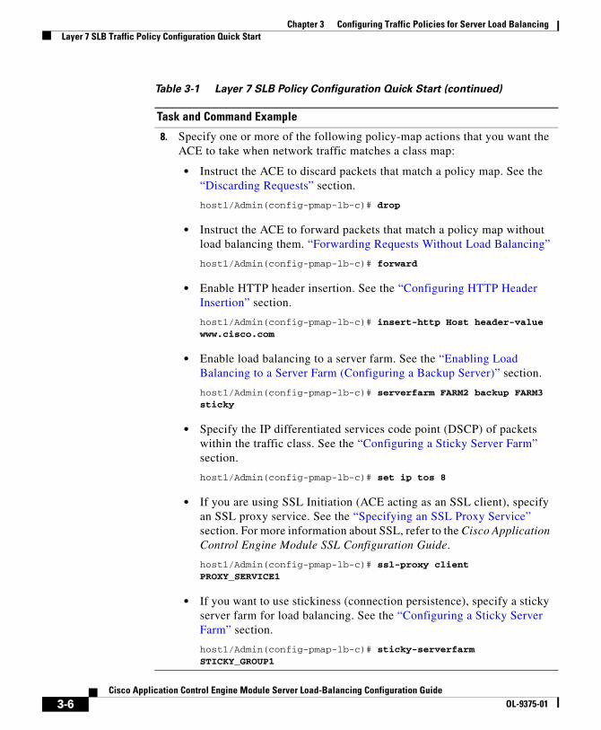
Chapter 3 Configuring Traffic Policies for Server Load BalancingLayer 7 SLB Traffic Policy Configuration Quick Start
8. Specify one or more of the following policy-map actions that you want the ACE to take when network traffic matches a class map:
• Instruct the ACE to discard packets that match a policy map. See the “Discarding Requests” section.
host1/Admin(config-pmap-lb-c)# drop
• Instruct the ACE to forward packets that match a policy map without load balancing them. “Forwarding Requests Without Load Balancing”
host1/Admin(config-pmap-lb-c)# forward
• Enable HTTP header insertion. See the “Configuring HTTP Header Insertion” section.
host1/Admin(config-pmap-lb-c)# insert-http Host header-value www.cisco.com
• Enable load balancing to a server farm. See the “Enabling Load Balancing to a Server Farm (Configuring a Backup Server)” section.
host1/Admin(config-pmap-lb-c)# serverfarm FARM2 backup FARM3 sticky
• Specify the IP differentiated services code point (DSCP) of packets within the traffic class. See the “Configuring a Sticky Server Farm” section.
host1/Admin(config-pmap-lb-c)# set ip tos 8
• If you are using SSL Initiation (ACE acting as an SSL client), specify an SSL proxy service. See the “Specifying an SSL Proxy Service” section. For more information about SSL, refer to the Cisco Application Control Engine Module SSL Configuration Guide.
host1/Admin(config-pmap-lb-c)# ssl-proxy client PROXY_SERVICE1
• If you want to use stickiness (connection persistence), specify a sticky server farm for load balancing. See the “Configuring a Sticky Server Farm” section.
host1/Admin(config-pmap-lb-c)# sticky-serverfarm STICKY_GROUP1
Table 3-1 Layer 7 SLB Policy Configuration Quick Start (continued)
Task and Command Example
3-6Cisco Application Control Engine Module Server Load-Balancing Configuration Guide
OL-9375-01

Chapter 3 Configuring Traffic Policies for Server Load BalancingLayer 7 SLB Traffic Policy Configuration Quick Start
9. Before you can use a Layer 7 policy map for load balancing, you must associate it with a Layer 3 and Layer 4 SLB policy map. Create the Layer 3 and Layer 4 class map and policy map, then associate the Layer 7 policy map with the Layer 3 and Layer 4 policy map. Finally, associate the Layer 3 and Layer 4 policy map with an interface. See the following sections:
• Configuring a Layer 3 and Layer 4 Class Map for SLB
• Configuring a Layer 3 and Layer 4 Policy Map for SLB
• Applying a Layer 3 and Layer 4 Policy to an Interface
10. (Recommended) Use the following commands to display your class-map and policy-map configurations and statistics (see the “Displaying Load-Balancing Configurational Information and Statistics” section):
host1/Admin# show running-config class-maphost1/Admin# show running-config policy-map
11. (Optional) If necessary, save your configuration changes to Flash memory.
host1/Admin# copy running-config startup-config
Table 3-1 Layer 7 SLB Policy Configuration Quick Start (continued)
Task and Command Example
3-7Cisco Application Control Engine Module Server Load-Balancing Configuration Guide
OL-9375-01

Chapter 3 Configuring Traffic Policies for Server Load BalancingLayer 3 and Layer 4 SLB Traffic Policy Configuration Quick Start
Layer 3 and Layer 4 SLB Traffic Policy Configuration Quick Start
Table 3-2 provides a quick overview of the steps required to configure a Layer 3 and Layer 4 class map and a Layer 3/4 policy map. Each step includes the CLI command and a reference to the procedure required to complete the task. For a complete description of each feature and all the options associated with the CLI commands, see the sections following Table 3-2.
Table 3-2 Layer 3 and Layer 4 SLB Policy Configuration Quick Start
Task and Command Example
1. If you are operating in multiple contexts, observe the CLI prompt to verify you are operating in the desired context. Change to, or directly log in to, the correct context if necessary.
host1/Admin# changeto C1host1/C1#
For details on creating contexts, refer to the Cisco Application Control Engine Module Virtualization Configuration Guide.
2. Enter configuration mode.
host1/Admin# configEnter configuration commands, one per line. End with CNTL/Zhost1/Admin(config)#
3. Create a Layer 3 and Layer 4 SLB class map. See the “Configuring a Layer 3 and Layer 4 Class Map for SLB” section.
host1/Admin(config)# class-map L4VIPCLASShost1/Admin(config-cmap)#
4. Define a virtual IP (VIP) address match statement. See the “Defining VIP Address Match Criteria” section.
host1/Admin(config-cmap)# match virtual-address 192.168.1.10 tcp port eq 80
5. Use the exit command to reenter configuration mode.
host1/Admin(config-cmap)# exithost1/Admin(config)#
3-8Cisco Application Control Engine Module Server Load-Balancing Configuration Guide
OL-9375-01

Chapter 3 Configuring Traffic Policies for Server Load BalancingLayer 3 and Layer 4 SLB Traffic Policy Configuration Quick Start
6. Create a Layer 3 and Layer 4 policy map. See the “Configuring a Layer 3 and Layer 4 Policy Map for SLB” section.
host1/Admin(config)# policy-map multi-match L4SLBPOLICYhost1/Admin(config-pmap)#
7. Associate the Layer 3 and Layer 4 class map that you created in step 2 with the policy map you created in step 4. See the “Associating a Layer 3 and Layer 4 Class Map with a Policy Map” section.
host1/Admin(config-pmap)# class L4VIPCLASShost1/Admin(config-pmap-c)#
8. Specify one or more of the following policy-map actions that you want the ACE to take when network traffic matches a class map:
• Enable the ACE to advertise the IP address of a virtual server as the host route. See the “Enabling the Advertising of a Virtual Server IP Address” section.
host1/Admin(config-pmap-c)# loadbalance vip advertise active frequency 30
• Enable a VIP to reply to ICMP ECHO requests. For example, if a user sends an ICMP ECHO request to a VIP, this command instructs the VIP to send an ICMP ECHO-REPLY. See the “Enabling a VIP to Reply to ICMP Requests” section.
host1/Admin(config-pmap-c)# loadbalance vip icmp-reply
• Associate a Layer 7 SLB policy map with the Layer 3 and Layer 4 policy map to provide an entry point for Layer 7 classifications. See the “Associating a Layer 7 SLB Policy Map with a Layer 3 and Layer 4 SLB Policy Map” section.
host1/Admin(config-pmap-c)# loadbalance policy L7SLBPOLICY
• Enable a VIP for SLB operations.
host1/Admin(config-pmap-c)# loadbalance vip inservice
Table 3-2 Layer 3 and Layer 4 SLB Policy Configuration Quick Start
(continued)
Task and Command Example
3-9Cisco Application Control Engine Module Server Load-Balancing Configuration Guide
OL-9375-01

Chapter 3 Configuring Traffic Policies for Server Load BalancingLayer 3 and Layer 4 SLB Traffic Policy Configuration Quick Start
9. Activate a policy map and attach it to an interface. See the “Applying a Layer 3 and Layer 4 Policy to an Interface” section.
host1/Admin(config)# interface VLAN50host1/Admin(config-if)# service-policy input L4SLBPOLICYhost1/Admin(config-if)# Ctrl-z
10. (Recommended) Use the following commands to display your class-map and policy-map configurations and statistics (see the “Displaying Load-Balancing Configurational Information and Statistics” section):
host1/Admin# show running-config class-maphost1/Admin# show running-config policy-maphost1/Admin# show service-policy name [detail]
11. (Optional) If necessary, save your configuration changes to Flash memory.
host1/Admin# copy running-config startup-config
Table 3-2 Layer 3 and Layer 4 SLB Policy Configuration Quick Start
(continued)
Task and Command Example
3-10Cisco Application Control Engine Module Server Load-Balancing Configuration Guide
OL-9375-01
Chapter 3 Configuring Traffic Policies for Server Load BalancingConfiguring Layer 7 Class Maps for SLB
Configuring Layer 7 Class Maps for SLBA Layer 7 SLB class map contains match criteria that classify specific Layer 7 network traffic. This section describes how to create a class map for Layer 7 SLB based on HTTP cookies, HTTP headers, HTTP URLs, source IP addresses, or SSL ciphers.
To create a Layer 7 class map for SLB and enter the class-map configuration mode, use the class-map type http loadbalance command in configuration mode. The syntax of this command is:
class-map type http loadbalance [match-all | match-any] map_name
You can configure multiple match commands in a single class map to specify the matching criteria. For example, you can configure a Layer 7 load-balancing class map to define multiple URLs, cookies, and HTTP headers in a group that you then associate with a traffic policy. The match-all and match-any keywords determine how the ACE evaluates multiple match statement operations when multiple match criteria exist in a class map.
The keywords, arguments, and options are:
• http loadbalance—Specifies a Layer 7 load-balancing class map.
• match-all | match-any—(Optional) Determines how the ACE evaluates Layer 7 HTTP SLB operations when multiple match criteria exist in a class map. The class map is considered a match if the match commands meet one of the following conditions:
– match-all —(Default) Network traffic needs to satisfy all of the match criteria (implicit AND) to match the Layer 7 load-balancing class map. The match-all keyword is applicable only for match statements of different Layer 7 load-balancing types. For example, specifying a match-all condition for URL, HTTP header, and URL cookie statements in the same class map is valid. However, specifying a match-all condition for multiple HTTP headers or multiple cookies with the same names or multiple URLs in the same class map is invalid.
3-11Cisco Application Control Engine Module Server Load-Balancing Configuration Guide
OL-9375-01

Chapter 3 Configuring Traffic Policies for Server Load BalancingConfiguring Layer 7 Class Maps for SLB
– match-any—Network traffic needs to satisfy only one of the match criteria (implicit OR) to match the HTTP load-balancing class map. The match-any keyword is applicable only for match statements of the same Layer 7 load-balancing type. For example, the ACE does not allow you to specify a match-any condition for URL, HTTP header, and URL cookie statements in the same class map but does allow you to specify a match-any condition for multiple URLs, or multiple HTTP headers or multiple cookies with different names in the same class map.
• map_name—Unique identifier assigned to the class map. Enter an unquoted text string with no spaces and a maximum of 64 alphanumeric characters. The class-map name is used for both the class map and to associate the class map with a policy map.
For example, to create a Layer 7 load-balancing class map named L7SLBCLASS, enter:host1/Admin(config)# class-map type http loadbalance match-any L7SLBCLASShost1/Admin(config-cmap-http-lb)#
To remove a Layer 7 load-balancing class map from the configuration, enter:
host1/Admin(config)# no class-map type http loadbalance match-any L7SLBCLASS
Continue with the following sections to specify match criteria for the Layer 7 class map:
• Configurational Considerations
• Defining a Cookie for HTTP Load Balancing
• Defining an HTTP Header for Load Balancing
• Defining a URL for HTTP Load Balancing
• Defining Source IP Address Match Criteria
• Nesting Layer 7 HTTP SLB Class Maps
3-12Cisco Application Control Engine Module Server Load-Balancing Configuration Guide
OL-9375-01
Chapter 3 Configuring Traffic Policies for Server Load BalancingConfiguring Layer 7 Class Maps for SLB
Configurational ConsiderationsWhen you are creating a class map for SLB, note the following configurational considerations:
• There can be a maximum of 10 total cookie names and header names for each Layer 3 and Layer 4 class. You can allocate the number of cookie names and header names in any combination as long as you do not exceed the maximum of 10.
• You can associate a maximum of 1024 instances of the same type of regex with each Layer 3 and Layer 4 policy map. This limit applies to all Layer 7 policy-map types, including generic, HTTP, RADIUS, RDP, RTSP, and SIP. You configure regexes in:
– Match statements in Layer 7 class maps
– Inline match statements in Layer 7 policy maps
– Layer 7 hash predictors for server farms
– Layer 7 sticky expressions in sticky groups
– Header insertion and rewrite (including SSL URL rewrite) expressions in Layer 7 action lists
• The ACE restricts the nesting of class maps to two levels to prevent you from including one nested class map in a different class map.
• The maximum number of class maps for each ACE is 8192.
Defining a Cookie for HTTP Load BalancingThe ACE performs regular expression matching against the received packet data from a particular connection based on the cookie expression. You can configure a maximum of 10 total cookie names and header names per class in any combination. To configure the class map to make Layer 7 SLB decisions based on the name and string of a cookie, use the match http cookie command in class-map configuration mode. The syntax of this command is:
[line_number] match http cookie {name | secondary name} cookie-value expression
3-13Cisco Application Control Engine Module Server Load-Balancing Configuration Guide
OL-9375-01
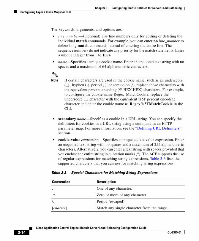
Chapter 3 Configuring Traffic Policies for Server Load BalancingConfiguring Layer 7 Class Maps for SLB
The keywords, arguments, and options are:
• line_number—(Optional) Use line numbers only for editing or deleting the individual match commands. For example, you can enter no line_number to delete long match commands instead of entering the entire line. The sequence numbers do not indicate any priority for the match statements. Enter a unique integer from 1 to 1024.
• name—Specifies a unique cookie name. Enter an unquoted text string with no spaces and a maximum of 64 alphanumeric characters.
Note If certain characters are used in the cookie name, such as an underscore (_), hyphen (-), period (.), or semicolon (:), replace those characters with the equivalent percent encoding (% HEX HEX) characters. For example, to configure the cookie name Regex_MatchCookie, replace the underscore (_) character with the equivalent %5F percent encoding character and enter the cookie name as Regex%5FMatchCookie in the CLI.
• secondary name—Specifies a cookie in a URL string. You can specify the delimiters for cookies in a URL string using a command in an HTTP parameter map. For more information, see the “Defining URL Delimiters” section.
• cookie-value expression—Specifies a unique cookie value expression. Enter an unquoted text string with no spaces and a maximum of 255 alphanumeric characters. Alternatively, you can enter a text string with spaces provided that you enclose the entire string in quotation marks (“). The ACE supports the use of regular expressions for matching string expressions. Table 3-3 lists the supported characters that you can use for matching string expressions.
Table 3-3 Special Characters for Matching String Expressions
Convention Description
. One of any character.
.* Zero or more of any character.
\. Period (escaped).
[charset] Match any single character from the range.
3-14Cisco Application Control Engine Module Server Load-Balancing Configuration Guide
OL-9375-01
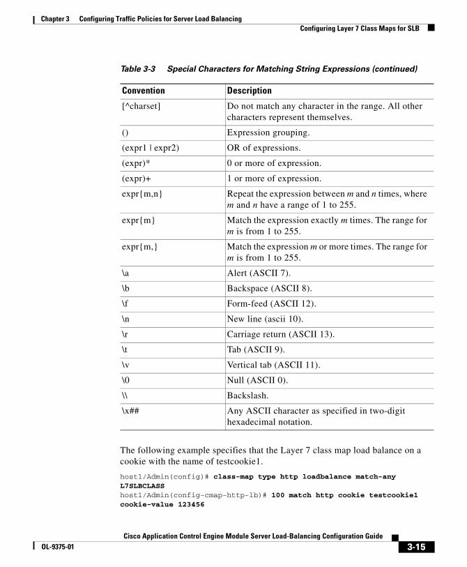
Chapter 3 Configuring Traffic Policies for Server Load BalancingConfiguring Layer 7 Class Maps for SLB
The following example specifies that the Layer 7 class map load balance on a cookie with the name of testcookie1.
host1/Admin(config)# class-map type http loadbalance match-any L7SLBCLASShost1/Admin(config-cmap-http-lb)# 100 match http cookie testcookie1 cookie-value 123456
[^charset] Do not match any character in the range. All other characters represent themselves.
() Expression grouping.
(expr1 | expr2) OR of expressions.
(expr)* 0 or more of expression.
(expr)+ 1 or more of expression.
expr{m,n} Repeat the expression between m and n times, where m and n have a range of 1 to 255.
expr{m} Match the expression exactly m times. The range for m is from 1 to 255.
expr{m,} Match the expression m or more times. The range for m is from 1 to 255.
\a Alert (ASCII 7).
\b Backspace (ASCII 8).
\f Form-feed (ASCII 12).
\n New line (ascii 10).
\r Carriage return (ASCII 13).
\t Tab (ASCII 9).
\v Vertical tab (ASCII 11).
\0 Null (ASCII 0).
\\ Backslash.
\x## Any ASCII character as specified in two-digit hexadecimal notation.
Table 3-3 Special Characters for Matching String Expressions (continued)
Convention Description
3-15Cisco Application Control Engine Module Server Load-Balancing Configuration Guide
OL-9375-01

Chapter 3 Configuring Traffic Policies for Server Load BalancingConfiguring Layer 7 Class Maps for SLB
To remove an HTTP cookie match statement from the class map, enter:
host1/Admin(config-cmap-http-lb)# no 100
Defining an HTTP Header for Load BalancingThe ACE performs regular expression matching against the received packet data from a particular connection based on the HTTP header expression. You can configure a maximum of 10 total HTTP header names and cookie names per class. To configure a class map to make Layer 7 SLB decisions based on the name and value of an HTTP header, use the match http header command in class-map configuration mode.
The syntax of this command is:
[line_number] match http header name header-value expression
The keywords, arguments, and options are:
• line_number—(Optional) Use line numbers only for editing or deleting the individual match commands. For example, you can enter no line_number to delete long match commands instead of entering the entire line. The sequence numbers do not indicate any priority for the match statements. Enter a unique integer from 1 to 1024.
• name—Specifies the name of the generic field in the HTTP header. Enter an unquoted text string with no spaces and a maximum of 64 alphanumeric characters. Alternatively, you can enter a text string with spaces provided that you enclose the entire string in quotation marks (“). For a list of standard header field names, see Table 3-4.
• header-value expression—Specifies the header value expression string to compare against the value in the specified field in the HTTP header. Enter a text string with a maximum of 255 alphanumeric characters. The ACE supports the use of regular expressions for header matching. Expressions are stored in a header map in the form header-name: expression. Header expressions allow spaces, provided that the entire string that contains spaces is quoted. If you use a match-all class map, all headers in the header map must be matched. See Table 3-3 for a list of the supported characters that you can use in regular expressions.
3-16Cisco Application Control Engine Module Server Load-Balancing Configuration Guide
OL-9375-01

Chapter 3 Configuring Traffic Policies for Server Load BalancingConfiguring Layer 7 Class Maps for SLB
Table 3-4 Standard HTTP Header Fields
Field Name Description
Accept A semicolon-separated list of representation schemes (content type metainformation values) that will be accepted in the response to the request.
Accept-Charset The character sets are acceptable for the response. This field allows clients capable of understanding more comprehensive or special-purpose character sets to signal that capability to a server that can represent documents in those character sets.
Accept-Encoding Restricts the content encoding that a user will accept from the server.
Accept-Language The ISO code for the language in which the document is written. The language code is an ISO 3316 language code with an optional ISO639 country code to specify a national variant.
Authorization Specifies that the user agent wants to authenticate itself with a server, usually after receiving a 401 response.
Cache-Control Directives that must be obeyed by all caching mechanisms along the request/response chain. The directives specify behavior intended to prevent caches from adversely interfering with the request or response.
Connection Allows the sender to specify connection options.
Content-MD5 An MD5 digest of the entity-body that provides an end-to-end integrity check. Only a client or an origin server can generate this header field.
Expect Used by a client to inform the server about what behaviors the client requires.
From Contains the e-mail address of the person that controls the requesting user agent.
3-17Cisco Application Control Engine Module Server Load-Balancing Configuration Guide
OL-9375-01
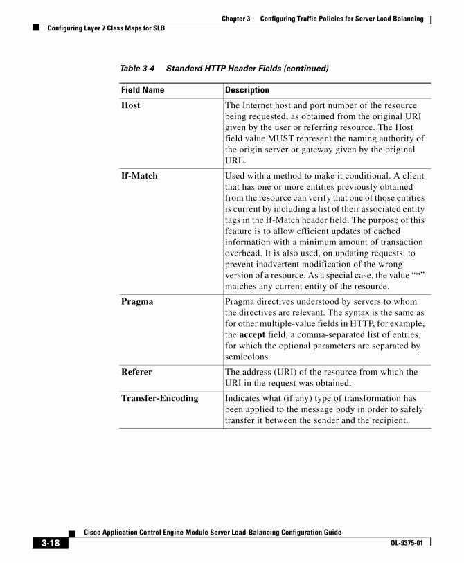
Chapter 3 Configuring Traffic Policies for Server Load BalancingConfiguring Layer 7 Class Maps for SLB
Host The Internet host and port number of the resource being requested, as obtained from the original URI given by the user or referring resource. The Host field value MUST represent the naming authority of the origin server or gateway given by the original URL.
If-Match Used with a method to make it conditional. A client that has one or more entities previously obtained from the resource can verify that one of those entities is current by including a list of their associated entity tags in the If-Match header field. The purpose of this feature is to allow efficient updates of cached information with a minimum amount of transaction overhead. It is also used, on updating requests, to prevent inadvertent modification of the wrong version of a resource. As a special case, the value “*” matches any current entity of the resource.
Pragma Pragma directives understood by servers to whom the directives are relevant. The syntax is the same as for other multiple-value fields in HTTP, for example, the accept field, a comma-separated list of entries, for which the optional parameters are separated by semicolons.
Referer The address (URI) of the resource from which the URI in the request was obtained.
Transfer-Encoding Indicates what (if any) type of transformation has been applied to the message body in order to safely transfer it between the sender and the recipient.
Table 3-4 Standard HTTP Header Fields (continued)
Field Name Description
3-18Cisco Application Control Engine Module Server Load-Balancing Configuration Guide
OL-9375-01
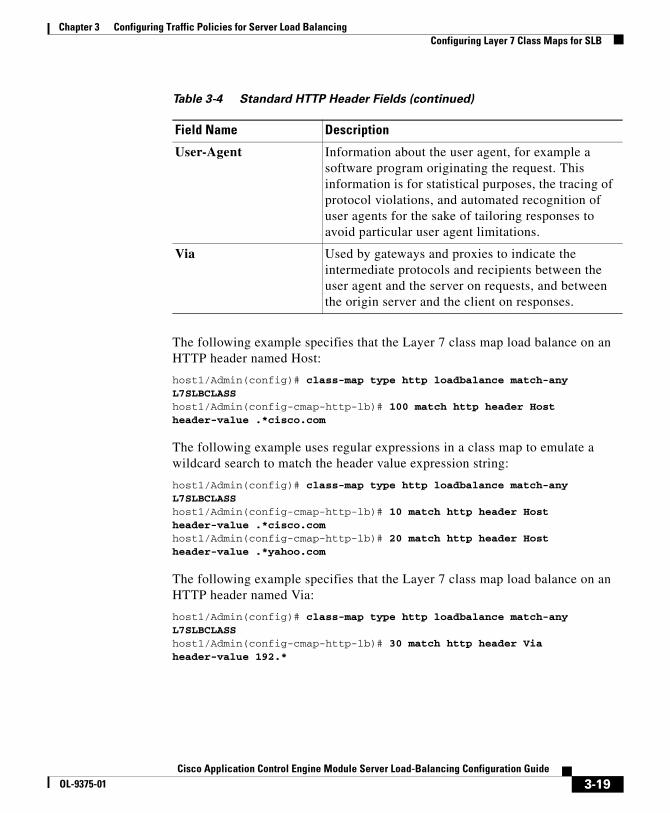
Chapter 3 Configuring Traffic Policies for Server Load BalancingConfiguring Layer 7 Class Maps for SLB
The following example specifies that the Layer 7 class map load balance on an HTTP header named Host:
host1/Admin(config)# class-map type http loadbalance match-any L7SLBCLASShost1/Admin(config-cmap-http-lb)# 100 match http header Host header-value .*cisco.com
The following example uses regular expressions in a class map to emulate a wildcard search to match the header value expression string:
host1/Admin(config)# class-map type http loadbalance match-any L7SLBCLASShost1/Admin(config-cmap-http-lb)# 10 match http header Host header-value .*cisco.comhost1/Admin(config-cmap-http-lb)# 20 match http header Host header-value .*yahoo.com
The following example specifies that the Layer 7 class map load balance on an HTTP header named Via:
host1/Admin(config)# class-map type http loadbalance match-any L7SLBCLASShost1/Admin(config-cmap-http-lb)# 30 match http header Via header-value 192.*
User-Agent Information about the user agent, for example a software program originating the request. This information is for statistical purposes, the tracing of protocol violations, and automated recognition of user agents for the sake of tailoring responses to avoid particular user agent limitations.
Via Used by gateways and proxies to indicate the intermediate protocols and recipients between the user agent and the server on requests, and between the origin server and the client on responses.
Table 3-4 Standard HTTP Header Fields (continued)
Field Name Description
3-19Cisco Application Control Engine Module Server Load-Balancing Configuration Guide
OL-9375-01
Chapter 3 Configuring Traffic Policies for Server Load BalancingConfiguring Layer 7 Class Maps for SLB
To remove all HTTP header match criteria from the L7SLBCLASS class map, enter:
host1/Admin(config-cmap-http-lb)# no 10host1/Admin(config-cmap-http-lb)# no 20host1/Admin(config-cmap-http-lb)# no 30
Defining a URL for HTTP Load BalancingThe ACE performs regular expression matching against the received packet data from a particular connection based on the HTTP URL string. To configure a class map to make Layer 7 SLB decisions based on URL name and, optionally, HTTP method, use the match http url command in class-map configuration mode. The syntax of this command is:
[line_number] match http url expression [method name]
The keywords, arguments, and options are:
• line_number—(Optional) Use line numbers only for editing or deleting the individual match commands. For example, you can enter no line_number to delete long match commands instead of entering the entire line. The line_number line numbers do not indicate any priority for the match statements. Enter a unique integer from 1 to 1024.
• expression—Specifies the URL, or portion of a URL, to match. Enter a URL string from 1 to 255 alphanumeric characters. The ACE performs matching on whatever URL string appears after the HTTP method, regardless of whether the URL includes the host name. The ACE supports the use of regular expressions for matching URL strings. See Table 3-3 for a list of the supported characters that you can use in regular expressions.
Note When matching URLs, keep in mind that period (.) and question mark (?) characters do not have a literal meaning in regular expressions. Use the “[]” character classes to match these symbols (for example, enter “www[.]xyz[.]com” instead of “www.xyz.com”). You can also use a backslash (\) to escape a dot (.) or a question mark (?).
3-20Cisco Application Control Engine Module Server Load-Balancing Configuration Guide
OL-9375-01
Chapter 3 Configuring Traffic Policies for Server Load BalancingConfiguring Layer 7 Class Maps for SLB
• method name—(Optional) Specifies the HTTP method to match. Enter a method name as an unquoted text string with no spaces and a maximum of 64 alphanumeric characters. The method can either be one of the standard HTTP 1.1 method names (OPTIONS, GET, HEAD, POST, PUT, DELETE, TRACE, or CONNECT) or a text string that must be matched exactly (for example, CORVETTE).
The following example specifies that the Layer 7 class map load balance on a specific URL.
host1/Admin(config)# class-map type http loadbalance L7SLBCLASShost1/Admin(config-cmap-http-lb)# 10 match http url /whatsnew/latest.*
The following example uses regular expressions to emulate a wildcard search to match on any .gif or .html file.
host1/Admin(config)# class-map type http loadbalance match-any L7SLBCLASShost1/Admin(config-cmap-http-lb)# 100 match http url .*.gifhost1/Admin(config-cmap-http-lb)# 200 match http url .*.html
To remove a URL match statement from the L7SLBCLASS class map, enter no and the line number. For example, to remove line 100, enter:
host1/Admin(config-cmap-http-lb)# no 100
Note If you did not use line numbers to enter the original URL match statement, you can obtain the line number from your running configuration. To display the running configuration, enter show running-config.
Defining Source IP Address Match CriteriaTo configure the class map to make Layer 7 SLB decisions based on a client source IP address, use the match source-address command in class-map configuration mode. If this command is the only match criteria in the class map, the ACE considers it to be a Layer 3 and Layer 4 class map.
The syntax of this command is:
[line_number] match source-address ip_address [netmask]
3-21Cisco Application Control Engine Module Server Load-Balancing Configuration Guide
OL-9375-01
Chapter 3 Configuring Traffic Policies for Server Load BalancingConfiguring Layer 7 Class Maps for SLB
The arguments and options are:
• line_number—(Optional) Use line numbers only for editing or deleting the individual match commands. For example, you can enter no line_number to delete long match commands instead of entering the entire line. The line numbers do not indicate any priority for the match statements. Enter a unique integer from 1 to 1024.
• ip_address—Source IP address of the client. Enter the IP address in dotted-decimal notation (for example, 192.168.11.2).
• netmask—(Optional) Subnet mask of the IP address. Enter the netmask in dotted-decimal notation (for example, 255.255.255.0). The default is 255.255.255.255.
The following example specifies that the class map match on source IP address 192.168.11.2 255.255.255.0.
host1/Admin(config)# class-map http type loadbalance match-any L7SLBCLASShost1/Admin(config-cmap-http-lb)# 50 match source-address 192.168.11.2 255.255.255.0
To remove the source IP address match statement from the class map, enter:
host1/Admin(config-cmap-http-lb)# no 50
Nesting Layer 7 HTTP SLB Class MapsThe nesting of class maps allows you to achieve complex logical expressions for Layer 7 HTTP-based SLB. To identify one Layer 7 HTTP SLB class map that is to be used as a matching criterion for another Layer 7 class map, use the match class-map command in class-map configuration mode.
Note The ACE restricts the nesting of class maps to two levels to prevent you from including a nested class map under another class map.
The syntax of this command is:
[line_number] match class-map map_name
3-22Cisco Application Control Engine Module Server Load-Balancing Configuration Guide
OL-9375-01

Chapter 3 Configuring Traffic Policies for Server Load BalancingConfiguring Layer 7 Class Maps for SLB
The keywords, arguments, and options are:
• line_number—(Optional) Inclusion of a line number can assist you in editing or deleting the individual match commands. For example, you can enter no line_number to delete long match commands instead of entering the entire line.
• map_name—Specifies the name of an existing Layer 7 load-balancing class map.
The match class-map command allows you to combine the use of the match-any and match-all keywords in the same class map. To combine match-all and match-any characteristics in a class map, create a class map that uses one match command (either match any or match all) and then use this class map as a match statement in a second class map that uses a different match type.
For example, assume that commands A, B, C, and D represent separate match criteria, and you want Layer 7 HTTP traffic that matches A, B, or C and D (A or B or [C and D]) to satisfy the class map. Without the use of nested class maps, traffic would either have to match all four match criteria (A and B and C and D) or match any of the match criteria (A or B or C or D) to satisfy the class map. By creating a single class map that uses the match-all keyword for match criteria C and D (criteria E), you can then create a new match-any class map that uses match criteria A, B, and E. The new traffic class contains your desired classification sequence: A or B or E, which is equivalent to A or B or [C and D].
The following example shows how to combine the characteristics of two class maps, one with match-any and one with match-all characteristics, into a single class map by using the match class-map command.
host1/Admin(config)# class-map type http loadbalance match-any CLASS3host1/Admin(config-cmap-http-lb)# 100 match http url .*.gifhost1/Admin(config-cmap-http-lb)# 200 match http header Host header-value XYZhost1/Admin(config-cmap-http-lb)# exit
host1/Admin(config)# class-map type http loadbalance match-all CLASS4host1/Admin(config-cmap-http-lb)# 10 match class-map CLASS3host1/Admin(config-cmap-http-lb)# 20 match source-address 192.168.11.2host1/Admin(config-cmap-http-lb)# exit
To remove the nested class map from the Layer 7 class map, enter:
host1/Admin(config-cmap-http-lb)# no 10
3-23Cisco Application Control Engine Module Server Load-Balancing Configuration Guide
OL-9375-01

Chapter 3 Configuring Traffic Policies for Server Load BalancingConfiguring a Layer 7 Policy Map for SLB
Configuring a Layer 7 Policy Map for SLBTo use a Layer 7 SLB policy map, first create the policy map and define match statements and policy actions. Because Layer 7 policy maps are child policies, you must then associate a Layer 7 policy map with the appropriate Layer 3 and Layer 4 policy map to provide an entry point for Layer 7 SLB traffic classification. You cannot directly apply a Layer 7 policy map on an interface; you can activate only a Layer 3 and Layer 4 policy map on an interface or globally on all interfaces in a context.
For background information on the role of policy maps in the ACE, refer to the Cisco Application Control Engine Module Administration Guide.
The ACE treats as a Layer 3 and Layer 4 policy any policy map that has only source IP configured as the match criteria in the class map or inline match, or that has the default class configured as the class map, and there are no Layer 7 policy actions configured.
To create a Layer 7 SLB policy map and enter policy-map configuration mode, use the policy-map type command in configuration mode. The syntax of this command is:
policy-map type loadbalance first-match map_name
The keywords and arguments are:
• loadbalance first-match—Specifies a policy map that defines Layer 7 HTTP SLB decisions. The first-match keyword defines the execution for the Layer 7 load-balancing policy-map. The ACE executes only the action specified against the first-matching classification.
• map_name—Specifies the identifier assigned to the policy map. Enter an unquoted text string with no spaces and a maximum of 64 alphanumeric characters.
The following example illustrates how to create a Layer 7 SLB policy map:
host1/Admin(config)# policy-map type loadbalance first-match L7SLBPOLICYhost1/Admin(config-pmap-lb)#
To remove a policy map from the ACE, enter:
host1/Admin(config)# no policy-map type loadbalance first-match L7SLBPOLICY
3-24Cisco Application Control Engine Module Server Load-Balancing Configuration Guide
OL-9375-01

Chapter 3 Configuring Traffic Policies for Server Load BalancingConfiguring a Layer 7 Policy Map for SLB
Continue with the following sections to enable the use of sequence numbers, define inline match statements, and define policy-map actions:
• Defining Match Statements Inline in a Layer 7 Policy Map
• Associating a Layer 7 Class Map with a Layer 7 Policy Map
• Specifying Layer 7 SLB Policy Actions
• Associating a Layer 7 Policy Map with a Layer 3 and Layer 4 Policy Map
Adding a Layer 7 Policy Map DescriptionUse the description command to provide a brief summary about the Layer 7 policy map.
Access the policy map configuration mode to specify the description command.
The syntax of this command is:
description text
Use the text argument to enter an unquoted text string with a maximum of 240 alphanumeric characters.
For example, to add a description that the policy map is to insert HTTP headers, enter:
host1/Admin(config-pmap-lb)# description insert HTTP headers
To remove the description from the policy map, enter:
host1/Admin(config-pmap-lb)# no description
Defining Match Statements Inline in a Layer 7 Policy MapLayer 7 SLB policy maps allow you to enter a single inline SLB match criteria in the policy map without specifying a traffic class. The inline Layer 7 SLB policy map match commands function the same as with the Layer 7 SLB class map match commands. However, when you use an inline match command, you can specify an action for only a single match statement in the Layer 7 policy.
Note To specify actions for multiple match statements, use a class map as described in the “Associating a Layer 7 Class Map with a Layer 7 Policy Map” section.
3-25Cisco Application Control Engine Module Server Load-Balancing Configuration Guide
OL-9375-01

Chapter 3 Configuring Traffic Policies for Server Load BalancingConfiguring a Layer 7 Policy Map for SLB
The syntax of an inline match command is:
match name1 match_statement [insert-before name2]
Note You can associate a maximum of 1024 instances of the same type of regex with each Layer 3 and Layer 4 policy map. This limit applies to all Layer 7 policy-map types, including generic, HTTP, RADIUS, RDP, RTSP, and SIP. You configure regexes in:
• Match statements in Layer 7 class maps
• Inline match statements in Layer 7 policy maps
• Layer 7 hash predictors for server farms
• Layer 7 sticky expressions in sticky groups
• Header insertion and rewrite (including SSL URL rewrite) expressions in Layer 7 action lists
The arguments and options are:
• name1—Specifies the name assigned to the inline match command. Enter an unquoted text string with no spaces and a maximum of 64 alphanumeric characters.
• match_statement—Specifies the individual Layer 7 SLB match criteria.
• insert-before name2—(Optional) Places the current match statement ahead of an existing class map or other match statement specified by the name2 argument in the policy-map configuration. The ACE does not save the sequence reordering as part of the configuration.
For information about configuring inline match statements in a Layer 7 SLB policy map, see the following sections in the “Configuring Layer 7 Class Maps for SLB” section:
• Defining a Cookie for HTTP Load Balancing
• Defining an HTTP Header for Load Balancing
• Defining a URL for HTTP Load Balancing
• Defining Source IP Address Match Criteria
3-26Cisco Application Control Engine Module Server Load-Balancing Configuration Guide
OL-9375-01
Chapter 3 Configuring Traffic Policies for Server Load BalancingConfiguring a Layer 7 Policy Map for SLB
Note The line_number argument described in the above-referenced sections is only for use with match statements in class maps. Otherwise, the descriptions of match statements in Layer 7 class maps and inline match statements in Layer 7 policy maps are the same.
Associating a Layer 7 Class Map with a Layer 7 Policy MapTo associate an existing Layer 7 class map with a Layer 7 policy map, use the class command. The syntax of this command is:
class {name1 [insert-before name2] | class-default}
The keywords, arguments, and options are:
• name1—Specifies the name of a previously defined traffic class, configured with the class-map command, to associate traffic to the traffic policy. Enter an unquoted text string with no spaces and a maximum of 64 alphanumeric characters.
• insert-before name2—(Optional) Places the current class map ahead of an existing class map or match statement specified by the name2 argument in the policy-map configuration. The ACE does not save the sequence reordering as part of the configuration.
• class-default—Reserved, well-known class map created by the ACE. You cannot delete or modify this class. All traffic that fails to meet the other matching criteria in the named class map belongs to the default traffic class. If none of the specified classifications match the traffic, then the ACE performs the action specified under the class class-default command. The class-default class map has an implicit match any statement in it enabling it to match all traffic.
The following example illustrates the use of the insert-before option to define the position of a class map in the policy map:
host1/Admin(config-pmap-lb)# class L7SLBCLASS insert-before http_classhost1/Admin(config-pmap-lb-c)#
To remove a class map from a Layer 7 policy map, enter:
host1/Admin(config-pmap-lb)# no class L7SLBCLASS
3-27Cisco Application Control Engine Module Server Load-Balancing Configuration Guide
OL-9375-01

Chapter 3 Configuring Traffic Policies for Server Load BalancingConfiguring a Layer 7 Policy Map for SLB
The following example illustrates the use of the class class-default command.
host1/Admin(config-pmap-lb)# class L7SLBCLASS insert-before http_classhost1/Admin(config-pmap-lb-c)# exithost1/Admin(config-pmap-lb)# class class-defaulthost1/Admin(config-pmap-lb-c)#
Specifying Layer 7 SLB Policy ActionsAfter you associate a Layer 7 SLB class map with a Layer 7 SLB policy map or specify inline match commands, you need to specify the actions that the ACE should take when network traffic matches a class map or inline match command. To specify the Layer 7 SLB policy actions, use the commands described in the following subsections:
• Discarding Requests
• Forwarding Requests Without Load Balancing
• Configuring HTTP Header Insertion
• Enabling Load Balancing to a Server Farm (Configuring a Backup Server)
• Configuring a Sorry Server Farm
• Configuring a Sticky Server Farm
• Specifying the IP Differentiated Services Code Point of Packets
• Specifying an SSL Proxy Service
Discarding Requests
To instruct the ACE to discard packets that match a particular policy map, use the drop command in load-balancing policy-map class configuration mode. The syntax of this command is:
drop
For example, enter:
host1/Admin(config-pmap-lb-c)# drop
To reset the behavior of the ACE to the default of accepting packets that match a policy map, enter:
host1/Admin(config-pmap-lb-c)# no drop
3-28Cisco Application Control Engine Module Server Load-Balancing Configuration Guide
OL-9375-01
Chapter 3 Configuring Traffic Policies for Server Load BalancingConfiguring a Layer 7 Policy Map for SLB
Forwarding Requests Without Load Balancing
To instruct the ACE to forward requests that match a particular policy map without performing loadbalancing on the request, use the forward command in load-balancing policy-map class configuration mode. The syntax of this command is:
forward
For example, enter:
host1/Admin(config-pmap-lb-c)# forward
To reset the behavior of the ACE to the default of loadbalancing packets that match a policy map, enter:
host1/Admin(config-pmap-lb-c)# no forward
Configuring HTTP Header Insertion
When the ACE uses network address translation (NAT) to translate the source IP address of a client to a VIP, servers need a way to identify that client for the TCP and IP return traffic. To identify a client whose source IP address has been NATed, you can instruct the ACE to insert a generic header and string value of your choice in the client HTTP request. For details about configuring NAT, see the Cisco Application Control Engine Module Security Configuration Guide.
Note With either TCP server reuse or persistence rebalance enabled, the ACE inserts a header in every client request. For information about TCP server reuse, see the “Configuring TCP Server Reuse” section. For information about persistence rebalance, see “Enabling HTTP Persistence Rebalance” section.
To insert a generic header and value in an HTTP request, use the insert-http command in policy map load balance class configuration mode. You can enter multiple insert-http commands for each class. The syntax of this command is:
insert-http name header-value expression
3-29Cisco Application Control Engine Module Server Load-Balancing Configuration Guide
OL-9375-01
Chapter 3 Configuring Traffic Policies for Server Load BalancingConfiguring a Layer 7 Policy Map for SLB
Note You can associate a maximum of 1024 instances of the same type of regex with each Layer 3 and Layer 4 policy map. This limit applies to all Layer 7 policy-map types, including generic, HTTP, RADIUS, RDP, RTSP, and SIP. You configure regexes in:
• Match statements in Layer 7 class maps
• Inline match statements in Layer 7 policy maps
• Layer 7 hash predictors for server farms
• Layer 7 sticky expressions in sticky groups
• Header insertion and rewrite (including SSL URL rewrite) expressions in Layer 7 action lists
The keywords and arguments are:
• name—Specifies the name of the HTTP header to insert in the client HTTP request. Enter an unquoted text string with no spaces and a maximum of 255 alphanumeric characters. You can specify any custom header name that you want, subject to the maximum character length. You can also enter any of the predefined header names in Table 3-4, regardless of whether that header name already exists in the client request header. The ACE does not overwrite any existing header information in the client request.
• header-value expression—Specifies the header-value expression string to insert in the HTTP header. Enter a text string with a maximum of 255 alphanumeric characters.
You can also specify the following special header-value expressions using the following special parameter values:
– %is—Inserts the source IP address in the HTTP header
– %id—Inserts the destination IP address in the HTTP header
– %ps—Inserts the source port in the HTTP header
– %pd—Inserts the destination port in the HTTP header
Note For Microsoft Outlook Web Access (OWA), specify the field name as HTTP_FRONT_END_HTTPS with a value of ON.
3-30Cisco Application Control Engine Module Server Load-Balancing Configuration Guide
OL-9375-01

Chapter 3 Configuring Traffic Policies for Server Load BalancingConfiguring a Layer 7 Policy Map for SLB
For example, in an SSL configuration, you could insert a generic field called ClientCert and the header value could be the client certificate or a portion thereof.
For example, to insert the header name Host with a header value of www.cisco.com in an HTTP client request header, enter:
host1/Admin(config)# policy-map type loadbalance first-match L7SLBPOLICYhost1/Admin(config-pmap-lb)# class L7SLBCLASShost1/Admin(config-pmap-lb-c)# insert-http Host header-value www.cisco.com
The header name and value will appear in the HTTP header as:
Host: www.cisco.com
To remove the HTTP header name and value from the policy map, enter:
host1/Admin(config-pmap-c)# no insert-http Host header-value www.cisco.com
Enabling Load Balancing to a Server Farm (Configuring a Backup Server)
To load-balance client requests for content to a server farm, use the serverfarm command in policy-map class configuration mode. Server farms are groups of networked real servers that contain the same content and that typically reside in the same physical location. The syntax of this command is:
serverfarm name1 [backup name2 [sticky] [aggregate-state]]
The keywords, arguments, and options are:
• name1—A unique identifier of the primary server farm. Enter an unquoted text string with no spaces and a maximum of 64 characters.
• backup name2—(Optional) Designates an existing server farm as a backup server farm in case all the servers in the original server farm become unavailable. When at least one server in the primary server farm becomes available again, the ACE sends all connections to the primary server farm. Enter the name of an existing server farm that you want to specify as a backup server farm as an unquoted text string with no spaces and a maximum of 64 alphanumeric characters.
3-31Cisco Application Control Engine Module Server Load-Balancing Configuration Guide
OL-9375-01
Chapter 3 Configuring Traffic Policies for Server Load BalancingConfiguring a Layer 7 Policy Map for SLB
Note If all servers in the server farm fail and you did not configure a backup server farm, the ACE sends a reset (RST) to a client in response to a content request.
• sticky—(Optional) Applies stickiness to the backup server farm. If all real servers in the primary server farm fail, the ACE sends client requests to the backup server farm. If you configure this sticky option, the backup server farm becomes sticky using source IP address stickiness by default. When at least one real server in the primary server farm becomes available again, the sticky backup server farm continues to service existing connections and new requests over existing sticky connections. The ACE sends all new connection requests to the primary server farm. If you want all connections to return to the primary server farm after it comes back up, do not configure this option. See the “Configuring a Sorry Server Farm” section.
• aggregate-state—(Optional, but recommended) Specifies that the state of the specified server farm is tied to the state of all the real servers in that server farm and in the backup server farm if configured. The ACE declares the primary server farm down if all real servers in the primary server farm and all real servers in the backup server farm are down.
The following example specifies the serverfarm command as an action in the load-balancing policy map.
host1/Admin(config)# policy-map type loadbalance first-match L7SLBPOLICYhost1/Admin(config-pmap-lb)# class L7SLBCLASShost1/Admin(config-pmap-lb-c)# serverfarm FARM2 backup FARM3 sticky
To remove the server-farm action from the Layer 7 load-balancing policy map, enter:
host1/Admin(config-pmap-lb-c)# no serverfarm FARM2
Configuring a Sorry Server Farm
When the primary server farm and any configured redirect servers are unavailable, you can instruct the ACE to send client requests to a sorry server farm. A sorry server is a server in a backup server farm with content stating that the Web page, resource, or service that a client requested is temporarily unavailable. When at least one server in the primary server farm returns to service, the ACE directs clients back to the primary server farm.
3-32Cisco Application Control Engine Module Server Load-Balancing Configuration Guide
OL-9375-01

Chapter 3 Configuring Traffic Policies for Server Load BalancingConfiguring a Layer 7 Policy Map for SLB
To configure a sorry server, use the serverfarm command in policy-map class configuration mode as described in the “Enabling Load Balancing to a Server Farm (Configuring a Backup Server)” section. In this case, configure a backup server farm, but do not use the sticky option of the backup keyword and do not associate the serverfarm with a sticky group. For more information about configuring stickiness, see Chapter 5, Configuring Stickiness. Also, configure the predictor hash source-ip command as the load-balancing method for the server farms. This predictor method guarantees that client connections will return to the primary server farm when it comes back up. For information about configuring the server farm predictor, see Chapter 2, Configuring Real Servers and Server Farms.
For example, to configure a sorry server farm, enter:
host1/Admin(config)# rserver SERVER1host1/Admin(config-rserver-host)# ip address 192.168.12.4host1/Admin(config-rserver-host)# inservicehost1/Admin(config)# rserver SERVER2host1/Admin(config-rserver-host)# ip address 192.168.12.5host1/Admin(config-rserver-host)# inservicehost1/Admin(config)# rserver SERVER3host1/Admin(config-rserver-host)# ip address 192.168.12.6host1/Admin(config-rserver-host)# inservicehost1/Admin(config)# rserver SERVER4host1/Admin(config-rserver-host)# ip address 192.168.12.7host1/Admin(config-rserver-host)# inservice
host1/Admin(config)# serverfarm SFARM1host1/Admin(config-sfarm-host)# predictor hash source-iphost1/Admin(config-sfarm-host)# rserver SERVER1host1/Admin(config-sfarm-host-rs)# inservicehost1/Admin(config-sfarm-host)# rserver SERVER2host1/Admin(config-sfarm-host-rs)# inservice
host1/Admin(config)# serverfarm SFARM2host1/Admin(config-sfarm-host)# predictor hash source-iphost1/Admin(config-sfarm-host)# rserver SERVER3host1/Admin(config-sfarm-host-rs)# inservicehost1/Admin(config-sfarm-host)# rserver SERVER4host1/Admin(config-sfarm-host-rs)# inservice
host1/Admin(config)# class-map type http loadbalance match-any L7SLBCLASShost1/Admin(config-cmap-http-lb)# 100 match http header Host header-value .*cisco.com
3-33Cisco Application Control Engine Module Server Load-Balancing Configuration Guide
OL-9375-01

Chapter 3 Configuring Traffic Policies for Server Load BalancingConfiguring a Layer 7 Policy Map for SLB
host1/Admin(config)# policy-map type loadbalance first-match L7SLBPOLICYhost1/Admin(config-pmap-lb)# class L7SLBCLASShost1/Admin(config-pmap-lb-c)# serverfarm SFARM1 backup SFARM2 aggregate-state
Configuring a Sticky Server Farm
To specify that requests matching a Layer 7 policy map be load balanced to a sticky server farm, use the sticky-serverfarm command in load-balancing policy-map class configuration mode. The syntax of this command is:
sticky-serverfarm name
The name argument specifies the identifier of an existing sticky group. Enter an unquoted text string with no spaces and a maximum of 64 alphanumeric characters. For information about sticky groups, see Chapter 5, Configuring Stickiness.
For example, enter:
host1/Admin(config)# policy-map type loadbalance first-match L7SLBPOLICYhost1/Admin(config-pmap-lb)# class L7SLBCLASShost1/Admin(config-pmap-lb-c)# sticky-serverfarm STICKY_GROUP1
To remove the sticky server farm from the policy map, enter:
host1/Admin(config-pmap-lb-c)# no sticky-serverfarm STICKY_GROUP1
Specifying the IP Differentiated Services Code Point of Packets
To specify the IP differentiated services code point (DSCP) of packets in a policy map, use the set ip tos command in policy-map class configuration mode. This command marks a packet by setting the IP DSCP bit in the Type of Service (TOS) byte. Once the IP DSCP bit is set, other Quality of Service (QoS) services can operate on the bit settings.
The syntax of this command is:
set ip tos value
The value argument specifies the IP DSCP value. Enter an integer from 0 to 255. The default is to not modify the ToS field.
3-34Cisco Application Control Engine Module Server Load-Balancing Configuration Guide
OL-9375-01

Chapter 3 Configuring Traffic Policies for Server Load BalancingConfiguring a Layer 7 Policy Map for SLB
The following example specifies the set ip tos command as a QoS action in the Layer 7 load-balancing policy map. All packets that satisfy the match criteria of L7SLBCLASS are marked with the IP DSCP value of 8. How packets marked with the IP DSCP value of 8 are treated is determined by the network configuration.
host1/Admin(config)# policy-map type loadbalance first-match L7SLBPOLICYhost1/Admin(config-pmap)# class L7SLBCLASShost1/Admin(config-pmap-lb-c)# set ip tos 8
To reset the ACE behavior to the default of not modifying the TOS byte value, enter:
host1/Admin(config-pmap-lb-c)# no set ip tos 8
Specifying an SSL Proxy Service
The ACE uses an SSL proxy service in a Layer 7 policy map to loadbalance outbound SSL initiation requests to SSL servers. In this case, the ACE acts as an SSL client sending an encrypted request to an SSL server. For more information about SSL initiation, refer to the Cisco Application Control Engine Module SSL Configuration Guide.
To specify an SSL proxy service in a policy map, use the ssl-proxy command in load-balancing policy-map class configuration mode. The syntax of this command is:
ssl-proxy client name
The name argument specifies the identifier of an existing SSL proxy service. Enter an unquoted text string with no spaces and a maximum of 64 alphanumeric characters.
For example, enter:
host1/Admin(config-pmap-lb-c)# ssl-proxy client PROXY_SERVICE1
To remove the SSL proxy service from the policy map, enter:
host1/Admin(config-pmap-lb-c)# no ssl-proxy client PROXY_SERVICE1
3-35Cisco Application Control Engine Module Server Load-Balancing Configuration Guide
OL-9375-01
Chapter 3 Configuring Traffic Policies for Server Load BalancingConfiguring an HTTP Parameter Map
Associating a Layer 7 Policy Map with a Layer 3 and Layer 4 Policy Map
To associate a Layer 7 SLB policy with a Layer 3 and Layer 4 SLB policy, use the service-policy type loadbalance command in policy-map class configuration mode. For details, see the “Associating a Layer 7 SLB Policy Map with a Layer 3 and Layer 4 SLB Policy Map” section.
Configuring an HTTP Parameter MapA parameter map is a means to combine related HTTP actions for use in a Layer 3 and Layer 4 policy map. You reference this parameter map in the policy map using the appl-parameter http advanced-options command. See the “Associating an HTTP Parameter Map with a Layer 3 and Layer 4 Policy Map” section.
To configure advanced HTTP behavior for SLB connections, use the parameter-map type http command in configuration mode. The syntax of this command is:
parameter-map type http name
The name argument specifies the identifier assigned to the parameter map. Enter an unquoted text string with no spaces and a maximum of 32 alphanumeric characters.
For example, enter:
host1/Admin(config)# parameter-map type http HTTP_PARAMETER_MAP
To remove an HTTP parameter map from the configuration, enter:
host1/Admin(config)# no parameter-map type http HTTP_PARAMETER_MAP
Use the commands in the following sections to define the advanced HTTP parameter map:
• Disabling Case Sensitivity Matching
• Defining URL Delimiters
• Setting the Maximum Number of Bytes to Parse for Cookies, HTTP Headers, and URLs
3-36Cisco Application Control Engine Module Server Load-Balancing Configuration Guide
OL-9375-01

Chapter 3 Configuring Traffic Policies for Server Load BalancingConfiguring an HTTP Parameter Map
• Configuring the ACE Behavior when a URL or Cookie Exceeds the Maximum Parse Length
• Enabling HTTP Persistence Rebalance
• Configuring TCP Server Reuse
Disabling Case Sensitivity MatchingBy default, the ACE CLI is case sensitive. To disable case-sensitivity matching for HTTP only, use the case-insensitive command in HTTP parameter-map configuration mode. With case-insensitive matching enabled, upper- and lower-case letters are considered the same. When case sensitivity is disabled, it applies to:
• HTTP header names and values
• HTTP cookie names and values
• URL strings
• HTTP deep inspection (for details, refer to the Cisco Application Control Engine Module Security Configuration Guide)
The syntax of this command is:
case-insensitive
For example, to disable case sensitivity, enter:
host1/Admin(config-parammap-http)# case-insensitive
To reenable case-sensitive matching after it has been disabled, enter:
host1/Admin(config-parammap-http)# no case-insensitive
Defining URL DelimitersTo define a list of ASCII-character delimiters that you can use to separate the cookies in a URL string, use the set secondary-cookie-delimiters command in HTTP parameter-map configuration mode. The syntax of this command is:
set secondary-cookie-delimiters text
3-37Cisco Application Control Engine Module Server Load-Balancing Configuration Guide
OL-9375-01
Chapter 3 Configuring Traffic Policies for Server Load BalancingConfiguring an HTTP Parameter Map
The text argument identifies the list of delimiters. Enter an unquoted text string with no spaces and a maximum of 4 characters. The order of the delimiters in the list does not matter. The default list of delimiters is: /&#+.
Cookies and their delimiters appear in GET request lines. In the following example of a GET request line, the ampersand (&) that appears between name-value pairs is the secondary cookie delimiter. The question mark (?) begins the URL query and is not configurable.
GET /default.cgi?user=me&hello=world&id=2 HTTP/1.1
For example, to specify the secondary cookie delimiters as !@#$, enter:
host1/Admin(config-parammap-http)# set secondary-cookie-delimiters !@#$
To reset the delimiter list to the default of /&#+, enter:
host1/Admin(config-parammap-http)# no set secondary-cookie-delimiters !@#$
Setting the Maximum Number of Bytes to Parse for Cookies, HTTP Headers, and URLs
By default, the maximum number of bytes that the ACE parses to check for a cookie, HTTP header, or URL is 2048. If a cookie, HTTP header, or URL exceeds the default value, the ACE drops the packet and sends a RST (reset) to the client browser. You can increase the number of bytes that the ACE parses using the set header-maxparse-length command in HTTP parameter-map configuration mode. The syntax of this command is:
set header-maxparse-length bytes
The bytes argument specifies the maximum number of bytes to parse for the total length of all cookies, HTTP headers, and URLs. Enter an integer from 1 to 65535. The default is 2048 bytes.
For example, to set the HTTP header maximum parse length to 8192, enter:
host1/Admin(config-parammap-http)# set header-maxparse-length 8192
To reset the HTTP header maximum parse length to the default of 2048 bytes, enter:
host1/Admin(config-parammap-http)# no set header-maxparse-length
3-38Cisco Application Control Engine Module Server Load-Balancing Configuration Guide
OL-9375-01

Chapter 3 Configuring Traffic Policies for Server Load BalancingConfiguring an HTTP Parameter Map
Configuring the ACE Behavior when a URL or Cookie Exceeds the Maximum Parse Length
To configure how the ACE handles cookies, HTTP headers, and URLs that exceed the maximum parse length, use the length-exceed command in HTTP parameter-map configuration mode. The syntax of this command is:
length-exceed {continue | drop}
The keywords are:
• continue—Continue load balancing. When you specify this keyword, the persistence-rebalance command is disabled if the total length of all cookies, HTTP headers, and URLs exceeds the maximum parse length value. For details on setting the maximum parse length, see the “Setting the Maximum Number of Bytes to Parse for Cookies, HTTP Headers, and URLs” section.
• drop—(Default) Stop load balancing and discard the packet.
For example, enter:
host1/Admin(config-parammap-http)# length-exceed continue
To reset the ACE behavior to the default of stopping load balancing and discarding a packet when its URL or cookie exceeds the maximum parse length, enter:
host1/Admin(config-parammap-http)# no length-exceed continue
Enabling HTTP Persistence RebalancePersistence is sometimes referred to as connection keepalive. With persistence rebalance enabled, each subsequent HTTP request on the same TCP connection is load balanced independently. Persistence rebalance allows the ACE to load-balance each HTTP request to a potentially different Layer 7 class and/or real server.
Another effect of persistence rebalance is that header insertion and cookie insertion, if enabled, occur for every request instead of only the first request. For information about header insertion, see the “Configuring HTTP Header Insertion” section in this chapter. For information about cookie insertion, see the “Enabling Cookie Insertion” section in Chapter 5, Configuring Stickiness.
3-39Cisco Application Control Engine Module Server Load-Balancing Configuration Guide
OL-9375-01

Chapter 3 Configuring Traffic Policies for Server Load BalancingConfiguring an HTTP Parameter Map
By default, persistence rebalance is disabled. To enable the persistence rebalance feature, use the persistence-rebalance command in HTTP parameter-map configuration mode. The syntax of this command is:
persistence-rebalance
Note If a real server is enabled with the NTLM Microsoft authentication protocol, we recommend that you leave persistence rebalance disabled. NTLM is a security measure that is used to perform authentication with Microsoft remote access protocols. When a real server is enabled with NTLM, every connection to the real server must be authenticated; typically, each client user will see a pop-up window prompting for a username and password. Once the connection is authenticated, all subsequent requests on the same connection will not be challenged. However, when the server load balancing function is enabled and configured with persistence rebalance, a subsequent request may point to a different real server causing a new authentication handshake.
The following example specifies the parameter-map type http command to configure URL cookie delimiter strings, set the maximum number of bytes to parse for URLs and cookies, and enable HTTP persistence:
host1/Admin(config)# parameter-map type http http_parameter_maphost1/Admin(config-parammap-http)# secondary-cookie-delimiters !@#$host1/Admin(config-parammap-http)# header-maxparse-length 4096 length-exceed continuehost1/Admin(config-parammap-http)# persistence-rebalance
To reset persistence to the default setting of disabled, enter:
host1/Admin(config-parammap-http)# no persistence-rebalance
3-40Cisco Application Control Engine Module Server Load-Balancing Configuration Guide
OL-9375-01
Chapter 3 Configuring Traffic Policies for Server Load BalancingConfiguring an HTTP Parameter Map
Configuring TCP Server ReuseTCP server reuse allows the ACE to reduce the number of open connections on a server by allowing connections to persist and be reused by multiple client connections. The ACE maintains a pool of TCP connections based on TCP options. New client connections can reuse those connections in the pool provided that the new client connections and prior server connections share the same TCP options. For information about configuring how the ACE handles TCP options, refer to the Cisco Application Control Engine Module Security Configuration Guide.
To ensure proper operation of this feature, observe the following TCP server reuse configurational recommendations and restrictions:
• Ensure that the ACE MSS is the same as the server MSS.
• Configure port address translation (PAT) on the interface that is connected to the real server. PAT prevents collisions when a client stops using a server connection and then that connection is reused by another client. Without PAT, if the original client tries to reuse the original server connection, it is no longer available. For details about configuring PAT, refer to the Cisco Application Control Engine Module Security Configuration Guide.
• Configure on the ACE the same TCP options that exist on the TCP server.
• Ensure that each server farm is homogeneous (all real servers within a server farm have identical configurations).
Another effect of TCP server reuse is that header insertion and cookie insertion, if enabled, occur for every request instead of only the first request. For information about header insertion, see the “Configuring HTTP Header Insertion” section in this chapter. For information about cookie insertion, see the “Enabling Cookie Insertion” section in Chapter 5, Configuring Stickiness.
To configure TCP server reuse use the server-conn reuse command in HTTP parameter-map configuration mode. The syntax of this command is:
server-conn reuse
For example, to enable TCP server reuse, enter:
host1/Admin(config-parammap-http)# server-conn reuse
To disable TCP server reuse, enter:
host1/Admin(config-parammap-http)# no server-conn reuse
3-41Cisco Application Control Engine Module Server Load-Balancing Configuration Guide
OL-9375-01
Chapter 3 Configuring Traffic Policies for Server Load BalancingConfiguring a Layer 3 and Layer 4 Class Map for SLB
To display TCP server reuse information, use the show conn detail command in Exec mode. For details, see .
Configuring a Layer 3 and Layer 4 Class Map for SLBA Layer 3 and Layer 4 class map contains match criteria to classify network traffic that can pass through the ACE. The ACE uses these Layer 3 and Layer 4 traffic classes to perform server load balancing (SLB). For a Layer 3 and Layer 4 traffic classification, the match criteria in a class map include the VIP address, protocol, and port of the ACE. You can configure multiple commands in a single class map to specify the match criteria in a group that you then associate with a traffic policy.
To create a Layer 3 and Layer 4 class map to classify network traffic passing through the ACE and enter class-map configuration mode, use the class-map command in configuration mode. The syntax of this command is:
class-map [match-all | match-any] map_name
The arguments and options are:
• match-all | match-any—(Optional) Determines how the ACE evaluates Layer 3 and Layer 4 network traffic when multiple match criteria exist in a class map. The class map is considered a match if the match commands meet one of the following conditions.
– match-all—(Default) Network traffic needs to satisfy all of the match criteria (implicit AND) to match the class map.
– match-any—Network traffic needs to satisfy only one of the match criteria (implicit OR) to match the load-balancing class map.
• map_name—Specifies the name assigned to the class map. Enter an unquoted text string with no spaces and a maximum of 64 alphanumeric characters. The class name is used for both the class map and to configure policy for the class in the policy map.
For example, to create a class map named L4VIPCLASS that specifies the network traffic must satisfy all the match criteria (match-all is the default), enter:
host1/Admin(config)# class-map L4VIPCLASS
To remove the class map from the configuration, enter:
host1/Admin(config)# no class-map L4VIPCLASS
3-42Cisco Application Control Engine Module Server Load-Balancing Configuration Guide
OL-9375-01

Chapter 3 Configuring Traffic Policies for Server Load BalancingConfiguring a Layer 3 and Layer 4 Class Map for SLB
After you have created a Layer 3 and Layer 4 class map for SLB, use the commands in the following sections to configure a description and the VIP match criteria for the class map:
• Defining a Class Map Description
• Defining VIP Address Match Criteria
Defining a Class Map DescriptionTo provide a brief summary about the Layer 3 and Layer 4 class map, use the description command in class-map configuration mode. The syntax of this command is:
description text
For the text argument, enter an unquoted text string with no spaces and a maximum of 240 alphanumeric characters.
The following example specifies a description that the class map is to filter network traffic to the server.
host1/Admin(config)# class-map match-any L4VIPCLASS host1/Admin(config-cmap)# description filter server traffic
To remove the description from the class map, enter:
host1/Admin(config-cmap)# no description
Defining VIP Address Match CriteriaTo define a 3-tuple flow of VIP address, protocol, and port as matching criteria for SLB, use the match virtual-address command in class-map configuration mode.You can configure multiple match criteria statements to define the VIPs for SLB. The syntax of this command is:
[line_number] match virtual-address vip_address {[mask] | any | {tcp | udp {any | eq port_number | range port1 port2}} | protocol_number}
3-43Cisco Application Control Engine Module Server Load-Balancing Configuration Guide
OL-9375-01
Chapter 3 Configuring Traffic Policies for Server Load BalancingConfiguring a Layer 3 and Layer 4 Class Map for SLB
The keywords, arguments, and options are:
• line_number—(Optional) Assists you in editing or deleting individual match commands. For example, you can enter no line_number to delete long match commands instead of entering the entire line.
• vip_address—Virtual IP (VIP) address of the virtual server in the ACE, specified in dotted-decimal notation (192.168.1.2). VIPs are public addresses owned by the customer.
• mask—(Optional) Mask for the VIP address of the ACE to allow connections to an entire network, specified in dotted decimal format (255.255.255.0).
• any—Wildcard value for the IP protocol value.
• tcp | udp—Specifies the protocol, TCP or UDP.
– any—Wildcard value for the TCP or UDP port number. With any used in place of either the eq or range values, packets from any incoming port match.
– eq port_number—Specifies that the TCP or UDP port number must match the specified value. Enter an inter from 0 to 65535. A value of 0 instructs the ACE to include all ports. Alternatively, you can enter the keyword name of a well-known TCP port from Table 3-5 or a well-known UDP port from Table 3-6.
Table 3-5 Well-Known TCP Port Numbers and Key Words
Key Word Port Number Description
domain 53 Domain Name System (DNS)
ftp 21 File Transfer Protocol (FTP)
ftp-data 20 FTP data connections
http 80 Hyper Text Transfer Protocol (HTTP)
https 443 HTTP over TLS or SSL (HTTPS)
irc 194 Internet Relay Chat (IRC)
matip-a 350 Mapping of Airline Traffic over Internet Protocol (MATIP) Type A
nntp 119 Network News Transport Protocol (NNTP)
pop2 109 Post Office Protocol (POP) v2
3-44Cisco Application Control Engine Module Server Load-Balancing Configuration Guide
OL-9375-01

Chapter 3 Configuring Traffic Policies for Server Load BalancingConfiguring a Layer 3 and Layer 4 Class Map for SLB
– range port1 port2—Specifies a port range to use for the TCP or UDP port. Valid port ranges are 0 to 65535. A value of 0 instructs the ACE to match all ports.
• protocol_number—Specifies the number of an IP protocol. Enter an integer from 1 to 254 that represents an IP protocol number.
pop3 110 Post Office Protocol (POP) v3
rtsp 554 Real Time Stream control Protocol (RTSP)
smtp 25 Simple Mail Transfer Protocol (SMTP)
telnet 23 Telnet
www 80 World Wide Web (WWW)
Table 3-6 Well-Known UDP Port Numbers and Key Words
Key Word Port Number Description
domain 53 Domain Name System
wsp 9200 Connectionless Wireless Session Protocol (WSP)
wsp-wtls 9202 Secure Connectionless WSP
wsp-wtp 9201 Connection-based WSP
wsp-wtp-wtls 9203 Secure Connection-based WSP
Table 3-5 Well-Known TCP Port Numbers and Key Words (continued)
Key Word Port Number Description
3-45Cisco Application Control Engine Module Server Load-Balancing Configuration Guide
OL-9375-01
Chapter 3 Configuring Traffic Policies for Server Load BalancingConfiguring a Layer 3 and Layer 4 Policy Map for SLB
Note The ACE always attempts to match incoming traffic to the configured classes in a Layer 4 multi-match policy on a first-match basis. When you configure two or more class maps with the same VIP address match criteria and you configure the protocol as any in the first class map, the ACE will not match incoming traffic to a more specific class map (one with a specified protocol and port) that follows the non-specific class map in a policy map. For example, if you configure match virtual-address 192.168.12.15 any in the first class map and match virtual-address 192.168.12.15 tcp eq https in the second class map and associate the classes in that order in a policy map, any HTTPS traffic received by the ACE will never match the intended class. Therefore, the ACE will loadbalance the traffic to the wrong server and you will receive The Page Cannot Be Displayed error in your browser. Always configure the more specific class first, or else you may experience unexpected results. If you configure the two classes in separate Layer 4 policy maps, be sure to apply the policies in the correct order on the interface using a service policy.
The following example specifies that the class map L4VIPCLASS matches traffic destined to VIP address 192.168.1.10 and TCP port number 80.
host1/Admin(config)# class-map L4VIPCLASShost1/Admin(config-cmap)# match virtual-address 192.168.1.10 tcp port eq 80
To remove the VIP match statement from the class map, enter:
host1/Admin(config-cmap)# no match virtual-address 192.168.1.10 tcp port eq 80
Configuring a Layer 3 and Layer 4 Policy Map for SLBFor a Layer 3 and Layer 4 SLB traffic classification, you create an SLB policy map that contains actions that are related to a VIP. A policy map associates a predefined traffic class (class map) with a series of actions to be performed on the traffic that matches the classifications defined in the traffic class. At the Layer 3 and Layer 4 network traffic level, there is a single policy map for each network traffic feature. The Layer 3 and Layer 4 policy maps are typed accordingly and, through the service-policy command, applied to a single interface or globally to all interfaces in a context.
3-46Cisco Application Control Engine Module Server Load-Balancing Configuration Guide
OL-9375-01

Chapter 3 Configuring Traffic Policies for Server Load BalancingConfiguring a Layer 3 and Layer 4 Policy Map for SLB
The sequence in which the ACE applies actions for a specific policy are independent of the actions configured for a class inside a policy. The ACE follows an implicit feature lookup order that is dictated by the policy map actions and features, which can mean that the user-configured order of class maps does not necessarily have an effect on the lookup order. For example, if you configure one or more security ACLs in a policy map, an ACL may not allow a certain flow through the ACE even if you want to perform operations such as SLB on that flow. For details on the lookup order that the ACE uses, refer to the Cisco Application Control Engine Module Administration Guide.
To create an SLB policy map, use the policy-map command in configuration mode. The syntax of this command is:
policy-map multi-match map_name
The keywords, arguments, and options are:
• multi-match—Allows the inclusion of multiple Layer 3 and Layer 4 network traffic-related actions in the same policy map, enabling the ACE to execute all possible actions applicable for a specific classification, for example, SLB, NAT (see the Cisco Application Control Engine Module Security Configuration Guide), and AAA.
• map_name—Specifies the unique identifier of the policy map. Enter an unquoted text string with no spaces and a maximum of 64 alphanumeric characters.
For example, to create a Layer 3 and Layer 4 network traffic policy map, enter:
host1/Admin(config)# policy-map multi-match L4SLBPOLICYhost1/Admin(config-pmap)#
To remove a policy map from the configuration, enter:
host1/Admin(config)# no policy-map multi-match L4SLBPOLICY
If there are multiple instances of actions of the same type (feature) configured in a policy map, the ACE performs the first action encountered of that type.
3-47Cisco Application Control Engine Module Server Load-Balancing Configuration Guide
OL-9375-01
Chapter 3 Configuring Traffic Policies for Server Load BalancingConfiguring a Layer 3 and Layer 4 Policy Map for SLB
Defining a Layer 3 and Layer 4 Policy Map DescriptionUse the description command to provide a brief summary about the Layer 3 and Layer 4 policy map.
Access the policy map configuration mode to specify the description command.
The syntax of this command is:
description text
Use the text argument to enter an unquoted text string with a maximum of 240 alphanumeric characters.
For example, to specify a description that the policy map is to filter network traffic to a VIP, enter:
host1/Admin(config-pmap)# description filter traffic matching a VIP
To remove the description from the class map, enter:
host1/Admin(config-pmap)# no description
Associating a Layer 3 and Layer 4 Class Map with a Policy MapTo associate a Layer 3 and Layer 4 SLB class map with a Layer 3 and Layer 4 SLB policy map, use the class command in policy-map configuration mode. The syntax of this command is:
class {name1 [insert-before name2] | class-default}
The keywords, arguments, and options are:
• name1—Specifies the name of a previously defined traffic class configured with the class-map command. Enter an unquoted text string with no spaces and a maximum of 64 alphanumeric characters.
• class-default—Reserved, well-known class map created by the ACE. You cannot delete or modify this class. All traffic that fails to meet the other matching criteria in the named class map belongs to the default traffic class. If none of the specified classifications match the traffic, then the ACE performs the action specified under the class class-default command. The class-default class map has an implicit match any statement in it enabling it to match all traffic.
3-48Cisco Application Control Engine Module Server Load-Balancing Configuration Guide
OL-9375-01

Chapter 3 Configuring Traffic Policies for Server Load BalancingConfiguring a Layer 3 and Layer 4 Policy Map for SLB
• insert-before name2—(Optional) Places the current class map ahead of an existing class map specified by the name2 argument in the policy-map configuration. The ACE does not preserve the command in the running conifguration, but does retain the configured order of class maps in the policy map.
The following example illustrates the use of the insert-before command to define the sequential order of two class maps in the policy map:
host1/Admin(config-pmap)# class L4VIPCLASS insert-before FILTERHTML
To remove a class map from a Layer 3 and Layer 4 policy map, enter:
host1/Admin(config-pmap)# no class L4VIPCLASS
Specifying Layer 3 and Layer 4 SLB Policy ActionsAfter you associate a Layer 3 and Layer 4 class map with an SLB policy map, you need to specify the actions that the ACE should take when network traffic matches one or more match statements in a class map. To specify the Layer 3 and Layer 4 SLB policy actions, use the commands described in the following subsections:
• Associating a Layer 7 SLB Policy Map with a Layer 3 and Layer 4 SLB Policy Map
• Associating an HTTP Parameter Map with a Layer 3 and Layer 4 Policy Map
• Associating a Connection Parameter Map with a Layer 3 and Layer 4 Policy Map
• Enabling the Advertising of a Virtual Server IP Address
• Enabling a VIP to Reply to ICMP Requests
• Enabling a VIP
Associating a Layer 7 SLB Policy Map with a Layer 3 and Layer 4 SLB Policy Map
The ACE treats all Layer 7 policy maps as child policies, so you must always associate a Layer 7 SLB policy map with a Layer 3 and Layer 4 SLB policy map. You can apply on an interface or globally on all interfaces in a context only a Layer 3 and Layer 4 policy map. For details on creating a Layer 7 load-balancing policy map, see the “Configuring a Layer 7 Policy Map for SLB” section.
3-49Cisco Application Control Engine Module Server Load-Balancing Configuration Guide
OL-9375-01
Chapter 3 Configuring Traffic Policies for Server Load BalancingConfiguring a Layer 3 and Layer 4 Policy Map for SLB
To associate a Layer 7 SLB policy map with a Layer 3 and Layer 4 SLB policy map, use the loadbalance command in policy-map class configuration mode.
The syntax of this command is:
loadbalance policy name
The policy name keyword and argument specifies the identifier of an existing Layer 7 SLB policy map. Enter the name as an unquoted text string with no spaces and a maximum of 64 alphanumeric characters.
The following example references the Layer 7 L7SLBPOLICY policy map within the Layer 3 and Layer 4 L4SLBPOLICY policy map.
host1/Admin(config)# policy-map type loadbalance first-match L7SLBPOLICYhost1/Admin(config-pmap-lb)# class L7SLBCLASShost1/Admin(config-pmap-lb-c)# serverfarm FARM2
host1/Admin(config)# policy-map multi-match L4SLBPOLICYhost1/Admin(config-pmap)# class L4SLBCLASShost1/Admin(config-pmap-c)# loadbalance policy L7SLBPOLICY
To dissociate the Layer 7 SLB policy from the Layer 3 and Layer 4 SLB policy, enter:
host1/Admin(config-pmap-c)# no loadbalance policy L7LBPOLICY
3-50Cisco Application Control Engine Module Server Load-Balancing Configuration Guide
OL-9375-01
Chapter 3 Configuring Traffic Policies for Server Load BalancingConfiguring a Layer 3 and Layer 4 Policy Map for SLB
Associating an HTTP Parameter Map with a Layer 3 and Layer 4 Policy Map
To configure advanced HTTP parameters, you can create a parameter map to define related actions. See the “Configuring an HTTP Parameter Map” section.
To associate an HTTP parameter map with a Layer 3 and Layer 4 policy map, use the appl-parameter http advanced-options command in policy-map class configuration mode.
The syntax of this command is:
appl-parameter http advanced-options name
The name argument identifies the name of an existing HTTP parameter map. Parameter maps aggregate HTTP traffic-related actions together. For details, see the “Configuring an HTTP Parameter Map” section.
The following example specifies the appl-parameter http advanced-options command as an action for the SLB policy map.
host1/Admin(config)# policy-map multi-match L4SLBPOLICYhost1/Admin(config-pmap)# class FILTERHTTPhost1/Admin(config-pmap-c)# appl-parameter http advanced-options HTTP_PARAM_MAP1
To dissociate the HTTP parameter map as an action from the SLB policy map, enter:
host1/Admin(config-pmap-c)# no appl-parameter http advanced-options HTTP_PARAM_MAP1
Associating a Connection Parameter Map with a Layer 3 and Layer 4 Policy Map
To configure TCP/IP normalization and connection parameters, you can create a connection parameter map to define related actions. Refer to the Cisco Application Control Engine Module Security Configuration Guide.
To associate a connection parameter map with a Layer 3 and Layer 4 policy map, use the connection advanced-options command in policy-map class configuration mode. The syntax of this command is:
connection advanced-options name
For the name argument enter the name of an existing parameter map as an unquoted text string with no spaces and a maximum of 64 alphanumeric characters.
3-51Cisco Application Control Engine Module Server Load-Balancing Configuration Guide
OL-9375-01
Chapter 3 Configuring Traffic Policies for Server Load BalancingConfiguring a Layer 3 and Layer 4 Policy Map for SLB
For example, enter:
host1/Admin(config-pmap-c)# connection advanced-options TCP_PARAM_MAP
To dissociate the TCP parameter map from a policy map, enter:
host1/Admin(config-pmap-c)# no connection advanced-options TCP_PARAM_MAP
Enabling the Advertising of a Virtual Server IP Address
To allow the ACE to advertise the IP address of the virtual server as the host route, use the loadbalance vip advertise command in policy-map class configuration mode. This function is used with route health injection (RHI) to allow the ACE to advertise the availability of a VIP address throughout the network.
The syntax of this command is:
loadbalance vip advertise [active] | [metric number]
The keywords, arguments, and options are:
• active—(Optional) Allows the ACE to advertise the IP address of the virtual server (VIP) as the host route only if there is at least one active real server in the server farm. Without the active option, the ACE always advertises the VIP whether or not there is any active real server associated with this VIP.
• metric number—(Optional) Specifies the distance metric for the route. Enter the metric value that needs to be entered in the routing table. Valid values are 1 through 254.
The following example specifies the advertise command as an action for the SLB policy map.
host1/Admin(config)# policy-map multi-match L4SLBPOLICYhost1/Admin(config-pmap)# class FILTERHTTPhost1/Admin(config-pmap-c)# loadbalance vip advertise active
To stop advertising the host route as an action from the SLB policy map, enter:
host1/Admin(config-pmap-c)# no loadbalance vip advertise active
3-52Cisco Application Control Engine Module Server Load-Balancing Configuration Guide
OL-9375-01
Chapter 3 Configuring Traffic Policies for Server Load BalancingConfiguring a Layer 3 and Layer 4 Policy Map for SLB
Enabling a VIP to Reply to ICMP Requests
To enable a VIP to reply to ICMP ECHO requests, use the loadbalance vip icmp-reply command in policy-map class configuration mode. For example, if a user sends an ICMP ECHO request to a VIP, this command instructs the VIP to send an ICMP ECHO-REPLY. The syntax of this command is:
loadbalance vip icmp-reply [active]
The active option instructs the ACE to reply to an ICMP request only if the configured VIP is active. If the VIP is not active and the active option is specified, the ACE discards the ICMP request and the request times out.
Note The loadbalance vip icmp-reply command alone controls a ping to a VIP on the ACE. This command implicitly downloads an ICMP access control list entry for the VIP. When you configure this command on the ACE, any configured ACLs that deny ICMP traffic have no effect on a client’s ability to ping the VIP.
To complete the configuration when you configure the active option of this command, be sure to configure a Telnet probe and associate it with the server farm. The probe monitors the health of all the real servers in the server farm and ensures that the VIP responds with an ICMP ECHO REPLY only if the server port is active. If the server port is down or unreachable, the probe fails and the VIP stops responding to the ECHO request. For details about configuring probes, see Chapter 4, Configuring Health Monitoring.
Note For security reasons, the ACE does not allow pings from an interface on a VLAN on one side of the ACE through the module to an interface on a different VLAN on the other side of the module. For example, you cannot ping a VIP from a server if the VIP is on a VLAN that is different from the server VLAN.
For example, enter:
host1/Admin(config)# policy-map multi-match L4SLBPOLICYhost1/Admin(config-pmap)# class FILTERHTTPhost1/Admin(config-pmap-c)# loadbalance vip icmp-reply active
3-53Cisco Application Control Engine Module Server Load-Balancing Configuration Guide
OL-9375-01
Chapter 3 Configuring Traffic Policies for Server Load BalancingApplying a Layer 3 and Layer 4 Policy to an Interface
Enabling a VIP
To enable a VIP for SLB operations, use the loadbalance vip inservice command in policy-map class configuration mode. The syntax of this command is:
loadbalance vip inservice
The following example specifies the loadbalance vip inservice command as an action for the SLB policy map.
host1/Admin(config)# policy-map multi-match L4SLBPOLICYhost1/Admin(config-pmap)# class FILTERHTTPhost1/Admin(config-pmap-c)# loadbalance vip icmp-reply activehost1/Admin(config-pmap-c)# loadbalance vip inservice
To disable a VIP, enter:
host1/Admin(config-pmap-c)# no loadbalance vip inservice
Applying a Layer 3 and Layer 4 Policy to an InterfaceUse the service-policy command to:
• Apply a previously created policy map.
• Attach the traffic policy to a specific VLAN interface or globally to all VLAN interfaces in the same context.
The service-policy command is available at both the interface configuration mode and at the configuration mode. Specifying a policy map in the configuration mode applies the policy to all of the VLAN interfaces associated with a context.
The syntax of this command is:
service-policy input policy_name
The keywords, arguments, and options are:
• input—Specifies that the traffic policy is to be attached to the input direction of an interface. The traffic policy evaluates all traffic received by that interface.
• policy_name—Specifies the name of a previously defined policy map, configured with a previously created policy-map command. The name can be a maximum of 64 alphanumeric characters.
3-54Cisco Application Control Engine Module Server Load-Balancing Configuration Guide
OL-9375-01
Chapter 3 Configuring Traffic Policies for Server Load BalancingApplying a Layer 3 and Layer 4 Policy to an Interface
Note the following when applying a service policy:
• Policy maps, applied globally in a context, are internally applied on all interfaces associated with the context.
• You can apply the policy in an input direction only.
• A policy activated on an interface overwrites any specified global policies for overlapping classification and actions.
• The ACE allows only one policy of a specific feature type to be activated on a given interface.
• You can configure a maximum of 4000 policy maps per ACE.
• You can apply a maximum of 128 service policies on each interface.
When you configure multiple VIPs on an interface, the match criteria for incoming traffic follow the order in which you configure the service-policy statements on that interface. Each service policy that you configure on an interface applies a Layer 3 and Layer 4 multi-match policy map to the interface. Each multi-match policy map may contain one or more features as defined in the class maps associated with the policy map.
Because service policies do not have line numbers, the order in which you configure them on an interface is extremely important. The reason is that the ACE has an implicit feature lookup order as follows:
1. Access control (permit or deny a packet)
2. Management traffic
3. TCP normalization and connection parameters
4. Server load balancing
5. Application protocol inspection
6. Source NAT
7. Destination NAT
When you apply multiple service policies to an interface, the ACE appends the last service policy at the end of the list. If you need to change the order of the service policies on an interface, you must first remove the service policies and then add them back in the appropriate order. This process is disruptive to the network.
3-55Cisco Application Control Engine Module Server Load-Balancing Configuration Guide
OL-9375-01

Chapter 3 Configuring Traffic Policies for Server Load BalancingApplying a Layer 3 and Layer 4 Policy to an Interface
As an alternative to reordering the service policies, you can configure multiple class maps in the same multi-match policy map, where you can define the order of the class maps. This process is not disruptive to the network. When you add new class maps to an existing policy, use the insert-before command to place the new class map in the desired order.
The following example shows how to configure two class maps in a policy map, where the VIP-ACCESS-MANAGER-80 is the more specific class map. To ensure that the ACE matches traffic to the more specific classification, configure VIP-ACCESS-MANAGER-80 class map first under the LB-TRAFFIC policy map. Note that this example and the one that follows include only the Layer 3 and Layer 4 traffic classification portions of the configuration.
class-map match-all VIP-ACCESS-MANAGER-ANY 2 match virtual-address 10.238.45.200 tcp eq anyclass-map match-all VIP-ACCESS-MANAGER-80 2 match virtual-address 10.238.45.200 tcp eq wwwpolicy-map multi-match LB-TRAFFIC class VIP-ACCESS-MANAGER-80 loadbalance vip inservice loadbalance policy POLICY-ACCESS-MANAGER-80 loadbalance vip icmp-reply active class VIP-ACCESS-MANAGER-ANY loadbalance vip inservice loadbalance policy POLICY-ACCESS-MANAGER-ANY loadbalance vip icmp-reply active
interface vlan 758 description CLIENT-SIDE-VLAN bridge-group 100 access-group input ALL service-policy input LB-TRAFFIC no shutdown
The following example shows how to use two policy maps, one for each class map, and achieve the same results as in the previous example. In this example, you configure the more specific policy map first under the interface using a service policy.
policy-map multi-match LB-TRAFFIC-80 class VIP-ACCESS-MANAGER-80 loadbalance vip inservice loadbalance policy POLICY-ACCESS-MANAGER-80 loadbalance vip icmp-reply active
3-56Cisco Application Control Engine Module Server Load-Balancing Configuration Guide
OL-9375-01
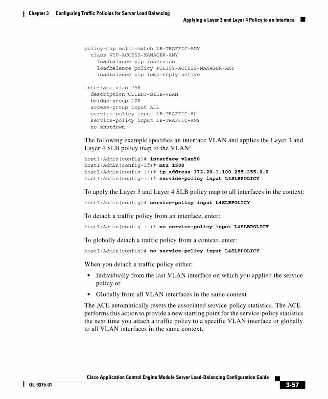
Chapter 3 Configuring Traffic Policies for Server Load BalancingApplying a Layer 3 and Layer 4 Policy to an Interface
policy-map multi-match LB-TRAFFIC-ANY class VIP-ACCESS-MANAGER-ANY loadbalance vip inservice loadbalance policy POLICY-ACCESS-MANAGER-ANY loadbalance vip icmp-reply active
interface vlan 758 description CLIENT-SIDE-VLAN bridge-group 100 access-group input ALL service-policy input LB-TRAFFIC-80 service-policy input LB-TRAFFIC-ANY no shutdown
The following example specifies an interface VLAN and applies the Layer 3 and Layer 4 SLB policy map to the VLAN:
host1/Admin(config)# interface vlan50host1/Admin(config-if)# mtu 1500host1/Admin(config-if)# ip address 172.20.1.100 255.255.0.0host1/Admin(config-if)# service-policy input L4SLBPOLICY
To apply the Layer 3 and Layer 4 SLB policy map to all interfaces in the context:
host1/Admin(config)# service-policy input L4SLBPOLICY
To detach a traffic policy from an interface, enter:
host1/Admin(config-if)# no service-policy input L4SLBPOLICY
To globally detach a traffic policy from a context, enter:
host1/Admin(config)# no service-policy input L4SLBPOLICY
When you detach a traffic policy either:
• Individually from the last VLAN interface on which you applied the service policy or
• Globally from all VLAN interfaces in the same context
The ACE automatically resets the associated service-policy statistics. The ACE performs this action to provide a new starting point for the service-policy statistics the next time you attach a traffic policy to a specific VLAN interface or globally to all VLAN interfaces in the same context.
3-57Cisco Application Control Engine Module Server Load-Balancing Configuration Guide
OL-9375-01
Chapter 3 Configuring Traffic Policies for Server Load BalancingDisplaying Load-Balancing Configurational Information and Statistics
Displaying Load-Balancing Configurational Information and Statistics
Use the commands in the following sections to display configurational information and statistics for Layer 3 and Layer 4, and Layer 7 class maps and policy maps. This section contains the following subsections:
• Displaying Class-Map Configurational Information
• Displaying Policy-Map Configurational Information
• Displaying Service-Policy Configurational Information
• Displaying Parameter Map Configurational Information
• Displaying Load-Balancing Statistics
• Displaying HTTP Parameter Map Statistics
• Displaying Service-Policy Statistics
Displaying Class-Map Configurational InformationTo display class-map configurational information, use the show running-config class-map command in Exec mode. This command displays the names of all the class maps configured in the contexts to which you have access and the match statements configured in each class map. The syntax of this command is:
show running-config class-map
Displaying Policy-Map Configurational InformationTo display policy-map configurational information, use the show running-config policy-map command in Exec mode. This command displays the names of all the policy maps configured in the contexts to which you have access and the class maps and actions configured in each policy map.
The syntax of this command is:
show running-config policy-map
3-58Cisco Application Control Engine Module Server Load-Balancing Configuration Guide
OL-9375-01
Chapter 3 Configuring Traffic Policies for Server Load BalancingDisplaying Load-Balancing Configurational Information and Statistics
Displaying Service-Policy Configurational InformationTo display service-policy configurational information, use the show running-config service-policy command in Exec mode. This command displays the names of all the service policies configured in the contexts to which you have access. The syntax of this command is:
show running-config service-policy
Displaying Parameter Map Configurational InformationTo display a list of parameter maps and their configurations, use the show running-config parameter-map command in Exec mode. The syntax of this command is:
show running-config parameter-map
Displaying Load-Balancing StatisticsTo display load-balancing statistics, use the show stats loadbalance command in Exec mode. The syntax of this command is:
show stats loadbalance
For example, enter:
host1/Admin# show stats loadbalance
3-59Cisco Application Control Engine Module Server Load-Balancing Configuration Guide
OL-9375-01
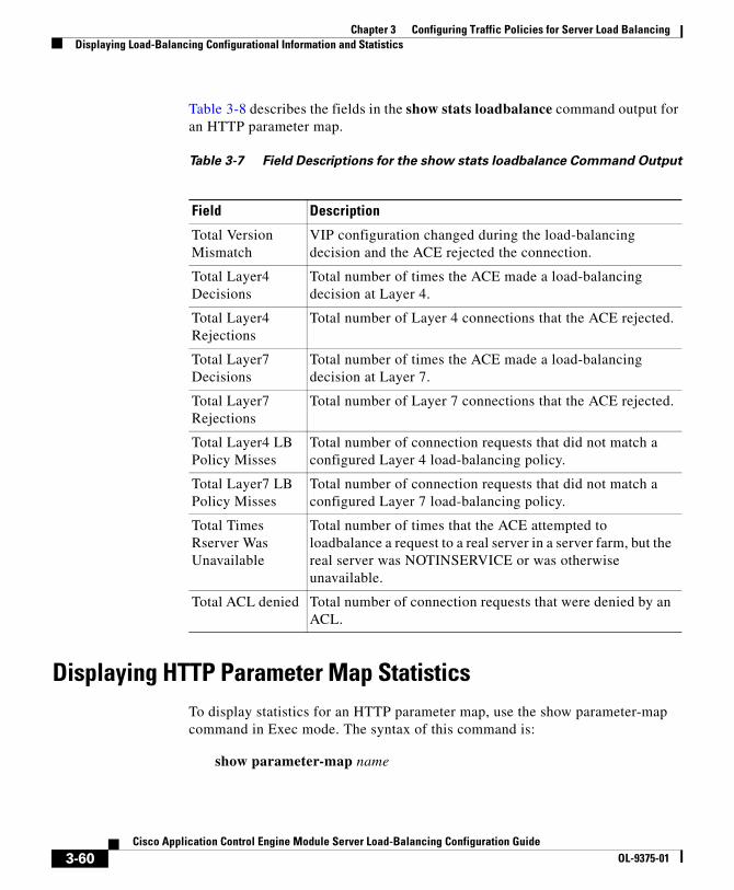
Chapter 3 Configuring Traffic Policies for Server Load BalancingDisplaying Load-Balancing Configurational Information and Statistics
Table 3-8 describes the fields in the show stats loadbalance command output for an HTTP parameter map.
Table 3-7 Field Descriptions for the show stats loadbalance Command Output
Field Description
Total Version Mismatch
VIP configuration changed during the load-balancing decision and the ACE rejected the connection.
Total Layer4 Decisions
Total number of times the ACE made a load-balancing decision at Layer 4.
Total Layer4 Rejections
Total number of Layer 4 connections that the ACE rejected.
Total Layer7 Decisions
Total number of times the ACE made a load-balancing decision at Layer 7.
Total Layer7 Rejections
Total number of Layer 7 connections that the ACE rejected.
Total Layer4 LB Policy Misses
Total number of connection requests that did not match a configured Layer 4 load-balancing policy.
Total Layer7 LB Policy Misses
Total number of connection requests that did not match a configured Layer 7 load-balancing policy.
Total Times Rserver Was Unavailable
Total number of times that the ACE attempted to loadbalance a request to a real server in a server farm, but the real server was NOTINSERVICE or was otherwise unavailable.
Total ACL denied Total number of connection requests that were denied by an ACL.
Displaying HTTP Parameter Map StatisticsTo display statistics for an HTTP parameter map, use the show parameter-map command in Exec mode. The syntax of this command is:
show parameter-map name
3-60Cisco Application Control Engine Module Server Load-Balancing Configuration Guide
OL-9375-01

Chapter 3 Configuring Traffic Policies for Server Load BalancingDisplaying Load-Balancing Configurational Information and Statistics
The name argument specifies the identifier of an HTTP parameter map. Enter an unquoted text string with a maximum of 64 alphanumeric characters.
For example, to display statistics for the HTTP parameter map called HTTP_PARAMMAP, enter:
host1/Admin# show parameter-map HTTP_PARAMMAP
Table 3-8 describes the fields in the show parameter-map command output for an HTTP parameter map.
Table 3-8 Field Descriptions for the show parameter-map Command Output
Field Description
Parameter-map Unique identifier of the HTTP parameter map
Type HTTP
Server-side connection reuse
Status of TCP server reuse feature: enabled or disabled
Case- insensitive parsing
Status of the case-insensitive command: enabled or disabled
Persistence- rebalance
Status of the persistence-rebalance command: enabled or disabled
Header- maxparse- length
Configured value or the default value of the header-maxparse-length command
Content- maxparse- length
Configured value or the default value of the content-maxparse-length command
Parse length- exceed action
Configured action for the length-exceed command: continue or drop
Urlcookie- delimiters
Configured URL cookie delimiters
3-61Cisco Application Control Engine Module Server Load-Balancing Configuration Guide
OL-9375-01

Chapter 3 Configuring Traffic Policies for Server Load BalancingDisplaying Load-Balancing Configurational Information and Statistics
Displaying Service-Policy StatisticsTo display statistics for service policies enabled globally within a context or on a specific interface, use the show service-policy command. The syntax of this command is:
show service-policy policy_name [detail]
The keywords, arguments, and options are:
• policy_name—Displays statistics for the specified existing policy map. Enter an unquoted text string with no spaces and a maximum of 64 alphanumeric characters.
• detail—(Optional) Displays detailed statistics for the specified policy map applied to an interface.
Note The ACE updates the counters that the show service-policy command displays after the applicable connections are closed.
Table 3-9 describes the fields in the show service-policy detail command output.
Table 3-9 Field Descriptions for the show service-policy detail Command
Output
Field Description
Status Current operational state of the service policy. Possible states are: ACTIVE or INACTIVE.
Description User-entered description of the policy map
Interface The VLAN ID of the interface to which the policy map has been applied
Service Policy Unique identifier of the policy map
Class Name of the class map associated with the service policy
Loadbalance
L7 Policy Name of the Layer 7 policy map associated with the service policy
3-62Cisco Application Control Engine Module Server Load-Balancing Configuration Guide
OL-9375-01
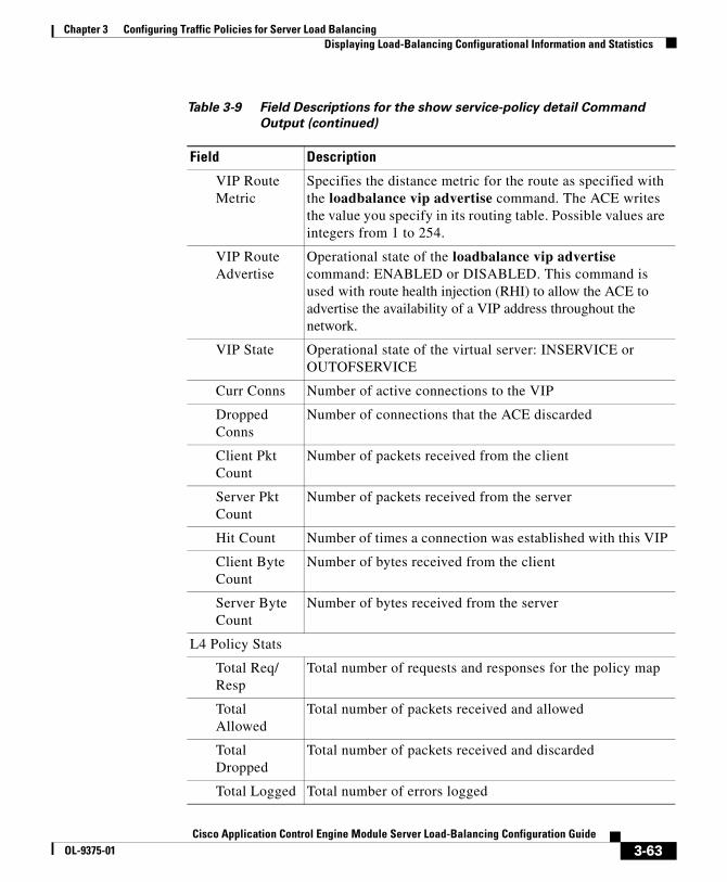
Chapter 3 Configuring Traffic Policies for Server Load BalancingDisplaying Load-Balancing Configurational Information and Statistics
VIP Route Metric
Specifies the distance metric for the route as specified with the loadbalance vip advertise command. The ACE writes the value you specify in its routing table. Possible values are integers from 1 to 254.
VIP Route Advertise
Operational state of the loadbalance vip advertise command: ENABLED or DISABLED. This command is used with route health injection (RHI) to allow the ACE to advertise the availability of a VIP address throughout the network.
VIP State Operational state of the virtual server: INSERVICE or OUTOFSERVICE
Curr Conns Number of active connections to the VIP
Dropped Conns
Number of connections that the ACE discarded
Client Pkt Count
Number of packets received from the client
Server Pkt Count
Number of packets received from the server
Hit Count Number of times a connection was established with this VIP
Client Byte Count
Number of bytes received from the client
Server Byte Count
Number of bytes received from the server
L4 Policy Stats
Total Req/ Resp
Total number of requests and responses for the policy map
Total Allowed
Total number of packets received and allowed
Total Dropped
Total number of packets received and discarded
Total Logged Total number of errors logged
Table 3-9 Field Descriptions for the show service-policy detail Command
Output (continued)
Field Description
3-63Cisco Application Control Engine Module Server Load-Balancing Configuration Guide
OL-9375-01
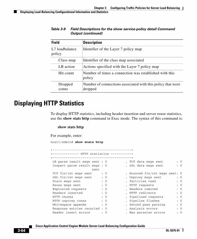
Chapter 3 Configuring Traffic Policies for Server Load BalancingDisplaying Load-Balancing Configurational Information and Statistics
Displaying HTTP StatisticsTo display HTTP statistics, including header insertion and server reuse statistics, use the show stats http command in Exec mode. The syntax of this command is:
show stats http
For example, enter:
host1/Admin# show stats http
+------------------------------------------++-------------- HTTP statistics -----------++------------------------------------------+ LB parse result msgs sent : 0 , TCP data msgs sent : 0 Inspect parse result msgs : 0 , SSL data msgs sent : 0 sent TCP fin/rst msgs sent : 0 , Bounced fin/rst msgs sent: 0 SSL fin/rst msgs sent : 0 , Unproxy msgs sent : 0 Drain msgs sent : 0 , Particles read : 0 Reuse msgs sent : 0 , HTTP requests : 0 Reproxied requests : 0 , Headers removed : 0 Headers inserted : 0 , HTTP redirects : 0 HTTP chunks : 0 , Pipelined requests : 0 HTTP unproxy conns : 0 , Pipeline flushes : 0 Whitespace appends : 0 , Second pass parsing : 0 Response entries recycled : 0 , Analysis errors : 0 Header insert errors : 0 , Max parselen errors : 0
L7 loadbalance policy
Identifier of the Layer 7 policy map
Class-map Identifier of the class map associated
LB action Actions specified with the Layer 7 policy map
Hit count Number of times a connection was established with this policy
Dropped conns
Number of connections associated with this policy that were dropped
Table 3-9 Field Descriptions for the show service-policy detail Command
Output (continued)
Field Description
3-64Cisco Application Control Engine Module Server Load-Balancing Configuration Guide
OL-9375-01

Chapter 3 Configuring Traffic Policies for Server Load BalancingClearing SLB Statistics
Static parse errors : 0 , Resource errors : 0 Invalid path errors : 0 , Bad HTTP version errors : 0
Clearing SLB StatisticsThis section describes the commands you can use to clear load-balancing statistics. It includes the following subsections:
• Clearing Load-Balancing Statistics
• Clearing Service-Policy Statistics
• Clearing HTTP Statistics
Clearing Load-Balancing StatisticsTo clear all load-balancing statistics in the current context, use the clear stats loadbalance command in Exec mode. The syntax of this command is:
clear stats loadbalance
For example, enter:
host1/Admin# clear stats loadbalance
Note If you have redundancy configured, then you need to explicitly clear load-balancing statistics on both the active and the standby ACEs. Clearing statistics on the active module alone will leave the standby module’s statistics at the old values.
Clearing Service-Policy StatisticsTo clear service policy statistics, use the clear service-policy command. The syntax of this command is:
clear service-policy policy_name
3-65Cisco Application Control Engine Module Server Load-Balancing Configuration Guide
OL-9375-01

Chapter 3 Configuring Traffic Policies for Server Load BalancingWhere to Go Next
For the policy_name argument, enter the identifier of an existing policy map that is currently in service (applied to an interface).
For example, to clear the statistics for the policy map L4SLBPOLICY that is currently in service, enter:
host1/Admin# clear service-policy L4SLBPOLICY
Note If you have redundancy configured, then you need to explicitly clear service-policy statistics on both the active and the standby ACEs. Clearing statistics on the active module alone will leave the standby module’s statistics at the old values.
Clearing HTTP StatisticsTo clear all HTTP statistics in the current context, use the clear stats http command in Exec mode. The syntax of this command is:
clear stats http
For example, enter:
host1/Admin# clear stats http
Note If you have redundancy configured, then you need to explicitly clear HTTP statistics on both the active and the standby ACEs. Clearing statistics on the active module alone will leave the standby module’s statistics at the old values.
Where to Go NextTo configure health probes for your real servers, proceed to Chapter 4, Configuring Health Monitoring. To configure stickiness (connection persistence), see Chapter 5, Configuring Stickiness. To configure firewall load balancing (FWLB), see Chapter 6, Configuring Firewall Load Balancing.
3-66Cisco Application Control Engine Module Server Load-Balancing Configuration Guide
OL-9375-01

Cisco Application Control Engine Module Server LOL-9375-01
C H A P T E R 4
Configuring Health MonitoringHealth monitoring on the ACE tracks the state of a server by sending out probes. Also referred as out-of-band health monitoring, the ACE verifies the server response or checks for any network problems that can prevent a client from reaching a server. Based on the server response, the ACE can place the server in or out of service, and can make reliable load balancing decisions.
You can also use health monitoring to detect failures for a gateway or host in high availability configurations. For more information, see the Cisco Application Content Engine Module Administration Guide.
The ACE identifies the health of a server in the following categories:
• Passed—The server returns a valid response.
• Failed—The server fails to provide a valid response to the ACE is unable to reach a server for a specified number of retries.
By configuring the ACE for health monitoring, the ACE sends active probes periodically to determine the server state. The ACE supports 4096 unique probe configurations which includes ICMP, TCP, HTTP, and other predefined health probes. The ACE also allows the opening of 1000 sockets simultaneously.
You can associate the same probe with multiple real servers or server farms. Each time that you use the same probe again, the ACE counts it as another probe instance. You can allocate a maximum of 16 K probe instances.
This chapter contains the following sections:
• Configuring Active Health Probes
• Displaying Probe Information
• Clearing Probe Statistics
4-1oad-Balancing Configuration Guide

Chapter 4 Configuring Health MonitoringConfiguring Active Health Probes
Configuring Active Health ProbesBy default, no active health probes are configured on the ACE. You can configure health probes on the ACE to actively make connections and explicitly send traffic to servers. The probes determine whether the health status of a server passes or fails by its response.
Configuring active probes is a three-step process:
• Configure the health probe with a name, type, and attributes.
• Associate the probe with one of the following:
– A real server.
– A real server and then associate the real server with a server farm. You can associate a single probe or multiple probes to real servers within a server farm.
– A server farm. All servers in the server farm receive probes of the associated probe types.
• Activate the real server or server farm.
For information on associating a probe with a real server or a server farm, and putting it into service, see the Chapter 2, Configuring Real Servers and Server Farms.
You can also configure one or more probes to track a gateway or host. For more information, see the Cisco Application Content Engine Module Administration Guide.
Defining an Active Probe and Accessing Probe Configuration Mode
When you initially configure a health probe, you define its type and name. The CLI then enters the probe configuration mode, which allows you to configure the attributes for the probe type.
To define a probe and access its configuration mode, use the probe command in configuration mode. The syntax of this command is:
probe probe_type probe_name
4-2Cisco Application Control Engine Module Server Load-Balancing Configuration Guide
OL-9375-01

Chapter 4 Configuring Health MonitoringConfiguring Active Health Probes
The arguments are:
• probe_type— The probe type that determines what the probe sends to the server. Enter one of the following keywords:
– icmp—Specifies an ICMP probe type and access its configuration mode. For configuration details, see the “Configuring an ICMP Probe” section.
– tcp—Specifies a TCP probe type and access its configuration mode. For configuration details, see the “Configuring a TCP Probe” section.
– udp—Specifies a UDP probe type and access its configuration mode. For configuration details, see the “Configuring a UDP Probe” section.
– echo {tcp | udp}—Specifies an ECHO TCP or UDP probe type and access its configuration mode. For configuration details, see the “Configuring Echo Probes” section.
– finger—Specifies a Finger probe type and access its configuration mode. For configuration details, see the “Configuring Finger Probes” section.
– http—Specifies an HTTP probe type and access its configuration mode. For configuration details, see the “Configuring an HTTP Probe” section.
– https—Specifies an HTTPS probe type for SSL and access its configuration mode. For configuration details, see the “Configuring an HTTPS Probe” section.
– ftp —Specifies an FTP probe type and access its configuration mode. For configuration details, see the “Configuring FTP Probes” section.
– telnet—Specifies a Telnet probe type and access its configuration mode. For configuration details, see the “Configuring Telnet Probes” section.
– dns—Specifies a DNS probe type and access its configuration mode. For configuration details, see the “Configuring DNS Probes” section.
– smtp—Specifies an SMTP probe type and access its configuration mode. For configuration details, see the “Configuring SMTP Probes” section.
– imap—Specifies a IMAP probe type and access its configuration mode. For configuration details, see the “Configuring an IMAP Probe” section.
– pop—Specifies a POP probe type and access its configuration mode. For configuration details, see the “Configuring a POP3 Probe” section.
– radius—Specifies a RADIUS probe type and access its configuration mode. For configuration details, see the “Configuring RADIUS Probe” section.
4-3Cisco Application Control Engine Module Server Load-Balancing Configuration Guide
OL-9375-01

Chapter 4 Configuring Health MonitoringConfiguring Active Health Probes
– scripted—Specifies a scripted probe type and access its configuration mode. For configuration details, see the “Configuring Scripted Probes” section. For information on scripts, see Appendix A, Using Toolkit Command Language (TCL) Scripts with the ACE.
• probe_name—The name you want to assign to the probe. You will use the probe name to associate the probe to the real server or server farm. Enter an unquoted text string with no spaces and a maximum of 64 characters.
For example, to define a TCP probe named PROBE1 and access the TCP probe configuration mode, enter:
host1/Admin(config)# probe tcp PROBE1host1/Admin(config-probe-tcp)#
To delete a TCP probe named PROBE1, enter:
host1/Admin(config)# no probe tcp PROBE1
There are some probe attributes and associated commands that apply to all probe types. For information on configuring these attributes, see the “Configuring General Probe Attributes” section.
Configuring General Probe AttributesWhen you access probe configuration mode to configure the attributes for the probe, the ACE provides a set of commands that you can configure for all probe types, except as indicated. The following sections describes how to configure the general attributes for a probe:
• Configuring a Probe Description
• Configuring the Destination IP Address
• Configuring the Port Number
• Configuring the Time Interval Between Probes
• Configuring the Retry Count for Failed Probes
• Configuring the Wait Period and Threshold for Successful Probes
• Configuring the Wait Interval for the Opening of the Connection
• Configuring the Timeout Period for a Probe Response
4-4Cisco Application Control Engine Module Server Load-Balancing Configuration Guide
OL-9375-01
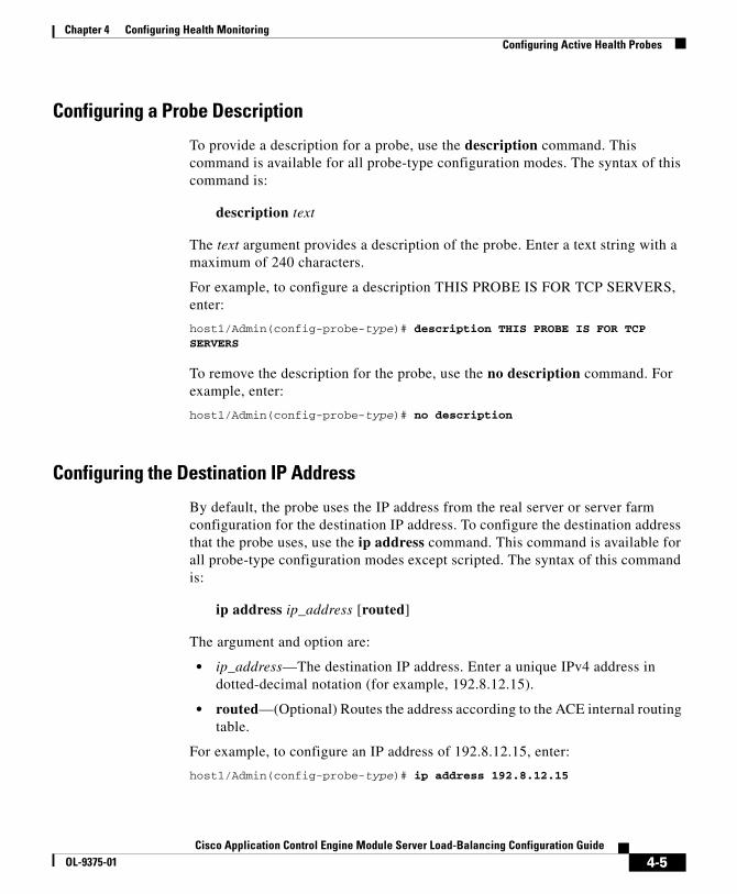
Chapter 4 Configuring Health MonitoringConfiguring Active Health Probes
Configuring a Probe Description
To provide a description for a probe, use the description command. This command is available for all probe-type configuration modes. The syntax of this command is:
description text
The text argument provides a description of the probe. Enter a text string with a maximum of 240 characters.
For example, to configure a description THIS PROBE IS FOR TCP SERVERS, enter:
host1/Admin(config-probe-type)# description THIS PROBE IS FOR TCP SERVERS
To remove the description for the probe, use the no description command. For example, enter:
host1/Admin(config-probe-type)# no description
Configuring the Destination IP Address
By default, the probe uses the IP address from the real server or server farm configuration for the destination IP address. To configure the destination address that the probe uses, use the ip address command. This command is available for all probe-type configuration modes except scripted. The syntax of this command is:
ip address ip_address [routed]
The argument and option are:
• ip_address—The destination IP address. Enter a unique IPv4 address in dotted-decimal notation (for example, 192.8.12.15).
• routed—(Optional) Routes the address according to the ACE internal routing table.
For example, to configure an IP address of 192.8.12.15, enter:
host1/Admin(config-probe-type)# ip address 192.8.12.15
4-5Cisco Application Control Engine Module Server Load-Balancing Configuration Guide
OL-9375-01

Chapter 4 Configuring Health MonitoringConfiguring Active Health Probes
To reset the default behavior of the probe using the IP address from the real server or server farm configuration, use the no ip address command. For example, enter:
host1/Admin(config-probe-type)# no ip address
Configuring the Port Number
By default, the probe uses the port number based on its type. Table 4-1 lists the default port numbers for each probe type.
Table 4-1 Default Port Numbers for Probe Types
Probe Type Default Port Number
ICMP Not applicable
TCP 80
UDP 53
HTTP 80
HTTPS 443
FTP 21
Telnet 23
Echo 7
Finger 79
IMAP 143
POP3 110
SMTP 25
DNS 53
RADIUS 1812
To configure the port number that the probe uses, use the port command. This command is available for all probes probe-type configuration modes except ICMP. The syntax of this command is:
port number
The number argument is the number of the port. Enter a number from 1 to 65535.
4-6Cisco Application Control Engine Module Server Load-Balancing Configuration Guide
OL-9375-01
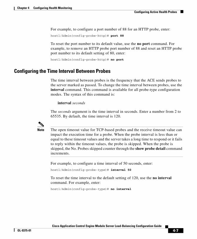
Chapter 4 Configuring Health MonitoringConfiguring Active Health Probes
For example, to configure a port number of 88 for an HTTP probe, enter:
host1/Admin(config-probe-http)# port 88
To reset the port number to its default value, use the no port command. For example, to remove an HTTP probe port number of 88 and reset an HTTP probe port number to its default setting of 80, enter:
host1/Admin(config-probe-http)# no port
Configuring the Time Interval Between Probes
The time interval between probes is the frequency that the ACE sends probes to the server marked as passed. To change the time interval between probes, use the interval command. This command is available for all probe-type configuration modes. The syntax of this command is:
interval seconds
The seconds argument is the time interval in seconds. Enter a number from 2 to 65535. By default, the time interval is 120.
Note The open timeout value for TCP-based probes and the receive timeout value can impact the execution time for a probe. When the probe interval is less than or equal to these timeout values and the server takes a long time to respond or it fails to reply within the timeout values, the probe is skipped. When the probe is skipped, the No. Probes skipped counter through the show probe detail command increments.
For example, to configure a time interval of 50 seconds, enter:
host1/Admin(config-probe-type)# interval 50
To reset the time interval to the default setting of 120, use the no interval command. For example, enter:
host1/Admin(config-probe-type)# no interval
4-7Cisco Application Control Engine Module Server Load-Balancing Configuration Guide
OL-9375-01

Chapter 4 Configuring Health MonitoringConfiguring Active Health Probes
Configuring the Retry Count for Failed Probes
Before the ACE marks a server as failed, it must detect that probes have failed a consecutive number of times. By default, when three consecutive probes have failed, the ACE marks the server as failed. To configure this number of failed probes, use the faildetect command. This command is available for all probe-type configuration modes. The syntax of this command is:
faildetect retry_count
The retry_count argument is the consecutive number of failed probes before marking the server as failed. Enter a number from 1 to 65535. By default, the count is 3.
For example, to configure the number of failed probes at 5 before declaring the server as failed, enter:
host1/Admin(config-probe-type)# faildetect 5
To reset the number of probe failures to the default setting of 3, use the no faildetect command. For example, enter:
host1/Admin(config-probe-type)# no faildetect
Configuring the Wait Period and Threshold for Successful Probes
After the ACE marks a server as failed, it waits a period of time and then sends a probe to the failed server. When the ACE receives a number of consecutive successful probes, it marks the server as passed. By default, the ACE waits 300 seconds before sending out a probe to a failed server and marks a server as passed if it receives 3 consecutive successful responses.
To configure the time interval to send a probe to a failed server and the number of probes to mark the server as passed, use the passdetect command. This command is available for all probe-type configuration modes. The syntax of this command is:
passdetect {interval seconds | count number}
The arguments are:
• interval seconds—Specifies the wait time interval in seconds. Enter a number from 2 to 65535. The default is 300.
4-8Cisco Application Control Engine Module Server Load-Balancing Configuration Guide
OL-9375-01

Chapter 4 Configuring Health MonitoringConfiguring Active Health Probes
• count number—Specifies the number of successful probe responses from the server. Enter a number from 1 to 65535. The default is 3.
Note The receive timeout value can impact the execution time for a probe. When the probe interval is less than or equal to this timeout value and the server takes a long time to respond or it fails to reply within the timeout value, the probe is skipped. When the probe is skipped, the No. Probes skipped counter through the show probe detail command increments.
For example, to configure wait interval at 10 seconds, enter:
host1/Admin(config-probe-type)# passdetect interval 10
For example, to configure five success probe responses from the server before declaring it as passed, enter:
host1/Admin(config-probe-type)# passdetect count 5
To reset the wait interval to its default setting, use the no passdetect interval command. For example, enter:
host1/Admin(config-probe-type)# no passdetect interval
To reset the successful probe responses to its default setting, use the no passdetect count command. For example, enter:
host1/Admin(config-probe-type)# no passdetect count
Configuring the Wait Interval for the Opening of the Connection
When the ACE sends a probe, it waits for the SYN-ACK after sending a SYN to open and then send an ACK to establish the connection with the server. To configure the time interval for a connection to be established, use the open command. This command is available in Echo TCP, Finger, FTP, HTTP, HTTPS, IMAP, POP, scripted, SMTP, TCP, and Telnet probe configuration mode (all TCP-based probes). The syntax of this command is:
open timeout
The timeout argument is the time to wait in seconds to open a connection with a server. Enter an integer from 1 to 65535. The default wait interval is 10 seconds.
4-9Cisco Application Control Engine Module Server Load-Balancing Configuration Guide
OL-9375-01

Chapter 4 Configuring Health MonitoringConfiguring Active Health Probes
Note The open timeout value for TCP-based probes and the receive timeout value can impact the execution time for a probe. When the probe interval is less than or equal to these timeout values and the server takes a long time to respond or it fails to reply within the timeout values, the probe is skipped. When the probe is skipped, the No. Probes skipped counter through the show probe detail command increments.
For example, to configure the wait time interval to 25 seconds, enter:
host1/Admin(config-probe-type)# open 25
To reset the time interval to its default setting of 10 seconds, use the no open command. For example, enter:
host1/Admin(config-probe-type)# no open
Configuring the Timeout Period for a Probe Response
By default, when the ACE sends a probe, it expects a response within a time period of 10 seconds. For example, for an HTTP probe, the timeout period is the number of seconds to receive an HTTP reply for a GET or HEAD request. If the server fails to respond to the probe, the ACE marks the server as failed.
To configure this time period to receive a server response to the probe, use the receive command. This command is available for all probe-type configuration modes. The syntax of this command is:
receive timeout
The timeout argument is the timeout period in seconds. Enter a number from 1 to 65535. By default, the timeout period is 10.
Note The open timeout value for TCP-based probes and the receive timeout value can impact the execution time for a probe. When the probe interval is less than or equal to these timeout values and the server takes a long time to respond or it fails to reply within the timeout values, the probe is skipped. When the probe is skipped, the No. Probes skipped counter through the show probe detail command increments.
4-10Cisco Application Control Engine Module Server Load-Balancing Configuration Guide
OL-9375-01

Chapter 4 Configuring Health MonitoringConfiguring Active Health Probes
For example, to configure the timeout period for a response at 5 seconds, enter:
host1/Admin(config-probe-type)# receive 5
To reset the time period to receive a response from the server to its default setting of 10 seconds, use the no receive command. For example, enter:
host1/Admin(config-probe-type)# no receive
Configuring an ICMP Probe An ICMP probe sends an ICMP echo request and listens for a response. If a server returns a response, the ACE marks the server as passed. If the server does not send a response causing the probe to time out, or the server sends an unexpected ICMP echo response type, the ACE marks the probe as failed.
To create an ICMP probe and access its configuration mode, use the probe icmp name command in configuration mode.
For example, to define a ICMP probe named PROBE3 and access its mode, enter:
host1/Admin(config)# probe icmp PROBE3host1/Admin(config-probe-icmp)#
Then, you can configure the attributes in the “Configuring General Probe Attributes” section.
Configuring a TCP ProbeA TCP probe initiates a TCP 3-way handshake and expects the server to send a response. By default, a successful response causes the probe to mark the server as passed. Then the probe sends a FIN to end the session. If the response is not valid or if there is no response, the probe marks the server as failed.
Optionally, you can configure the probe to send a RST or specific data, and to expect specific response in order to mark the server as passed. You can also configure the probe to send specific data and receive a specific response from the server. If the response is not valid or there is no response, the probe marks the server as failed.
To create a TCP probe and access its configuration mode, use the probe tcp name command in configuration mode.
4-11Cisco Application Control Engine Module Server Load-Balancing Configuration Guide
OL-9375-01
Chapter 4 Configuring Health MonitoringConfiguring Active Health Probes
For example, to define a TCP probe named PROBE1 and access its mode, enter:
host1/Admin(config)# probe tcp PROBE1host1/Admin(config-probe-tcp)#
You can configure attributes for a TCP probe, as described in the following sections:
• Configuring the Termination of the TCP Connection
• Configuring an Expected String from the Server
• Configuring Data that the Probe Sends to the Server Upon Connection
Then, you can configure the attributes in the “Configuring General Probe Attributes” section.
Configuring the Termination of the TCP Connection
A TCP probe makes a connection and if the connection through a 3-way handshake (SYN, SYN-ACK, and ACK) is successful, the probe is marked as pass. By default, the ACE terminates a TCP connection gracefully by sending a FIN to the server.
Note If a probe is configured for the default graceful connection termination (FIN) and the target server does not send the expected data, the probe terminates the TCP connection to the server with a reset (RST). The probe will continue to send a RST to terminate the server connection as long as the returned data is not the expected data. When the server responds with the correct data again, the probe reverts to terminating the connection with a FIN.
To configure the ACE to terminate a TCP connection by sending a RST, use the connection term command. This command is available for TCP-based connection-oriented probes (ECHO TCP, Finger, FTP, HTTP, HTTPS, IMAP, POP, SMTP, TCP, and Telnet probe configuration modes). The syntax of this command is:
connection term forced
For example, enter:
host1/Admin(config-probe-tcp)# connection term forced
4-12Cisco Application Control Engine Module Server Load-Balancing Configuration Guide
OL-9375-01
Chapter 4 Configuring Health MonitoringConfiguring Active Health Probes
To reset the method to terminate a connection gracefully, use the no connection term command. For example, enter:
host1/Admin(config-probe-tcp)# no connection term forced
Configuring an Expected String from the Server
When you configure a probe to expect a string from a server, it searches the response for a configured string. If the ACE finds the expected string, the server is marked as passed. If you do not configure an expected string, the ACE ignores the server response.
Note For HTTP or HTTPS probes, the server response must include the Content-Length header for the expect regex command to function. Otherwise, the probe does not attempt to parse the regex string.
To configure what the ACE expects as a response string from the probe destination server, use the expect regex command. This command is available in Finger, HTTP, HTTPS, TCP, and UDP probe configuration modes. The syntax of this command is:
expect regex string [offset number]
The argument and option are:
• string—The expected response string from the probe destination. Enter an unquoted text string with no spaces. If the string includes spaces, enclose the string in quotes. The string can be a maximum of 255 characters.
• offset number—(Optional) Sets the number of characters into the received message or buffer where to start searching for the defined expression. Enter a number from 1 to 4000.
Note If you configure the expect regex command for TCP probes, you must configure the send-data command. Otherwise, the probe opens and closes the connection without checking the response from the server.
For example, to configure the ACE to expect a response string of ack, enter:
host1/Admin(config-probe-tcp)# expect regex ack
4-13Cisco Application Control Engine Module Server Load-Balancing Configuration Guide
OL-9375-01

Chapter 4 Configuring Health MonitoringConfiguring Active Health Probes
To remove the expectation of a response string for TCP and UDP probes, use the no expect command. For example, enter:
host1/Admin(config-probe-tcp)# no expect
To remove the expectation of a response string for HTTP and HTTPS probes, use the no expect regex command. For example, enter:
host1/Admin(config-probe-http)# no expect regex
Configuring Data that the Probe Sends to the Server Upon Connection
To configure the ASCII data that the probe sends when the ACE connects to the server, use the send-data command. This command is available in ECHO, Finger, TCP, and UDP probe configuration modes. The syntax of this command is:
send-data expression
The expression argument is the data that the probe sends. Enter an unquoted text string with a maximum of 255 characters including spaces.
Note If you do not configure the send-data command for a UDP probe, the probe sends one byte, 0x00.
For example, to configure the probe to send TEST as the data, enter:
host1/Admin(config-probe-tcp)# send-data test
To remove the data, use the no send-data command. For example, enter:
host1/Admin(config-probe-tcp)# no send-data
4-14Cisco Application Control Engine Module Server Load-Balancing Configuration Guide
OL-9375-01
Chapter 4 Configuring Health MonitoringConfiguring Active Health Probes
Configuring a UDP Probe
Note When configuring a UDP probe, you must configure a management-based policy. For more information on policies, see the Cisco Application Control Engine Module Administration Guide.
By default, the UDP probe sends a UDP packet to a server and marks the server as failed only if the server returns an ICMP Port Unreachable message. If the ACE does not receive any ICMP errors for the UDP request that was sent, the probe is marked as passed. Optionally, you can configure this probe to send specific data and expect a specific response to mark the server as passed.
If the IP interface of the server is down or disconnected, the UDP probe by itself would not know that the UDP application is not reachable.
To create a UDP probe and access its configuration mode, use the probe udp name command.
For example, to define a UDP probe named PROBE2 and access its mode, enter:
host1/Admin(config)# probe udp PROBE2host1/Admin(config-probe-udp)#
You can configure the following attributes for a UDP probe:
• To configure what the ACE expects as a response from the probe destination server, use the expect regex command. For more detailed information on this command, see the “Configuring an Expected String from the Server” section.
• To configure the data sent on the connection for a UDP probe, use the send-data expression command. For more detailed information on this command, see the “Configuring Data that the Probe Sends to the Server Upon Connection” section.
Then, you can configure the attributes in the “Configuring General Probe Attributes” section.
4-15Cisco Application Control Engine Module Server Load-Balancing Configuration Guide
OL-9375-01

Chapter 4 Configuring Health MonitoringConfiguring Active Health Probes
Configuring Echo ProbesThe Echo probe sends a specified string to the server and compares the response with the original string. You must configure the string that needs to be echoed. If the response string matches the original string, the server is marked as passed. If you do not configure a string, the probe behaves like a TCP or UDP probe, respectively.
To create an Echo probe and access its configuration mode, use the probe echo command. The syntax of this command is:
probe echo {tcp | udp} name
The keywords and argument are:
• name—Identifier of the probe. Enter an unquoted text string with a maximum of 64 alphanumeric characters.
• tcp—Configures the probe for a TCP connection.
• udp—Configures the probe for a UDP connection.
For example, to define an Echo probe using TCP named PROBE and access its mode, enter:
host1/Admin(config)# probe echo tcp PROBEhost1/Admin(config-probe-echo-tcp)#
For example, to define an Echo probe using UDP named PROBE17 and access its mode, enter:
host1/Admin(config)# probe echo udp PROBE17host1/Admin(config-probe-echo-udp)#
For Echo TCP or UDP probes, you can configure the attributes in the “Configuring General Probe Attributes” section.
For a TCP connection, as configured through the tcp keyword, you can also configure the attributes in the “Configuring a TCP Probe” section.
For a UDP connection, as configured through the udp keyword, you can also configure the attributes in the “Configuring a UDP Probe” section.
4-16Cisco Application Control Engine Module Server Load-Balancing Configuration Guide
OL-9375-01
Chapter 4 Configuring Health MonitoringConfiguring Active Health Probes
Configuring Finger ProbesThe Finger probe uses a Finger query to a server for an expected response string. The ACE searches the response for the configured string. If the ACE finds the expected response string, the server is marked as passed. If you do not configure an expected response string, the ACE ignores the server response.
To create a Finger probe and access its configuration mode, use the probe finger command. The syntax of this command is:
probe finger name
The name argument is the identifier of the probe. Enter an unquoted text string with no spaces and a maximum of 64 alphanumeric characters.
For example, to define a Finger probe named PROBE8 and access its mode, enter:
host1/Admin(config)# probe finger PROBE8host1/Admin(config-probe-finger)#
To configure the attributes for a Finger probe, you can configure the attributes in the “Configuring General Probe Attributes” and “Configuring a TCP Probe” sections.
Configuring an HTTP ProbeAn HTTP probe establishes a TCP connection and issues an HTTP request to the server for an expected string and status code. The ACE can compare the received response with configured codes, looking for a configured string in the received HTTP page, or verifying hash for the HTTP page. If any of these checks fail, the server is marked as failed.
For example, if you configure an expected string and status code and the ACE finds them both in the server response, the server is marked as passed. However, if the ACE does not receive either the server response string or the expected status code, it marks the server as failed.
4-17Cisco Application Control Engine Module Server Load-Balancing Configuration Guide
OL-9375-01

Chapter 4 Configuring Health MonitoringConfiguring Active Health Probes
Note If you do not configure an expected status code, any response from the server is marked as failed. The server response must include the Content-Length header for the expect regex or hash command to function. Otherwise, the probe does not attempt to parse the regex or hash value.
To create an HTTP probe and access its configuration mode, use the probe http name command. For example, to define an HTTP probe named PROBE4 and access its mode, enter:
host1/Admin(config)# probe http PROBE4host1/Admin(config-probe-http)#
You can configure attributes for an HTTP probe, as described in the following sections:
• Configuring the Credentials for a Probe
• Configuring the Header Field for the HTTP Probe
• Configuring the HTTP Method for the Probe
• Configuring the Status Code from the Destination Server
• Configuring an MD5 Hash Value
Then, you can configure the general attributes in the “Configuring General Probe Attributes” section. You can also configure TCP probe attributes including an expected response string in the “Configuring a TCP Probe” section.
Configuring the Credentials for a Probe
The credentials for a probe are the username and password used for authentication on the server. To configure the credentials for the probe, use the credentials command. The syntax of this command is:
credentials username [password]
The arguments are:
• username—The user identifier used for authentication. Enter an unquoted text string with a maximum of 64 characters.
4-18Cisco Application Control Engine Module Server Load-Balancing Configuration Guide
OL-9375-01

Chapter 4 Configuring Health MonitoringConfiguring Active Health Probes
• password—(Optional) The password used for authentication. Enter an unquoted text string with a maximum of 64 characters.
For example, to configure the username ENG1 and a password TEST, enter:
host1/Admin(config-probe-http)# credentials ENG1 TEST
To delete the credentials for the probe, use the no credentials command. For example, enter:
host1/Admin(config-probe-http)# no credentials
Configuring the Header Field for the HTTP Probe
To configure an HTTP header or multiple header fields for the HTTP probe, use the header command. The syntax of this command is:
header field_name header-value value
The arguments are:
• field_name—The identifier for a standard header field. Enter a text string with a maximum of 64 characters. If the header field includes spaces, enclose its string with quotes. You can also enter one of the following header keywords:
– Accept—Accept request header
– Accept-Charset—Accept-Charset request header
– Accept-Encoding—Accept-Encoding request header
– Accept-Language—Accept-Language request header
– Authorization—Authorization request header
– Cache-Control—Cache-Control general header
– Connection—Connection general header
– Content-MD5—Content-MD5 entity header
– Expect—Expect request header
– From—From request header
– Host—Host request header
– If-Match—If-Match request header
4-19Cisco Application Control Engine Module Server Load-Balancing Configuration Guide
OL-9375-01
Chapter 4 Configuring Health MonitoringConfiguring Active Health Probes
– Pragma—Pragma general header
– Referer—Referer request header
– Transfer-Encoding—Transfer-Encoding general header
– User-Agent—User-Agent request header
– Via—Via general header
• header-value field_value—Specifies the value assigned to the header field. Enter a text string with a maximum of 255 characters. If the value string includes spaces, enclose the string with quotes.
For example, to configure the Accept-Encoding HTTP header with a field value of IDENTITY, enter:
host1/Admin(config-probe-http)# header Accept-Encoding header-value IDENTITY
To remove the header configuration for the probe, use the no form of the header command. For example, to remove a header with the Accept-Encoding field name, enter:
host1/Admin(config-probe-http)# no header Accept-Encoding
Configuring the HTTP Method for the Probe
By default, the HTTP request method is a GET with the URL “/”. If you do not configure a URL, the probe behaves as a TCP probe.
To configure the HTTP method and URL used by the probe, use the request method command. The syntax of this command is:
request method {get | head} url path
The keywords and arguments are:
• get | head—Configures the HTTP request method. The keywords are:
– get —The HTTP GET request method directs the server to get the page. This method is the default.
– head —The HTTP HEAD request method directs the server to get only the header for the page.
• url path—Specifies the URL path. The path argument specifies the character string of up to 255 characters specifies the URL path. The default path is “/”.
4-20Cisco Application Control Engine Module Server Load-Balancing Configuration Guide
OL-9375-01

Chapter 4 Configuring Health MonitoringConfiguring Active Health Probes
For example, to configure the HEAD HTTP method and the /digital/media/graphics.html URL used by an HTTP probe, enter:
host1/Admin(config-probe-http)# request method head url /digital/media/graphics.html
To reset the HTTP method for the probe to GET, use the no request method command. For example, enter:
host1/Admin(config-probe-http)# no request method head url /digital/media/graphics.html
Configuring the Status Code from the Destination Server
When the ACE receives a response from the server, it expects a status code to mark a server as passed. By default, there are no status codes configured on the ACE. If you do not configure a status code, any response code from the server is marked as failed.
To configure a single or range of code responses that the ACE expects from the probe destination, use the expect status command. You can specify multiple status code ranges with this command by entering the command with different ranges separately. The syntax of this command is:
expect status min_number max_number
The arguments and options are:
• min_number—Specifies a single status code or the lower limit of a range of status codes. Enter an integer from 0 to 999.
• max_number—Specifies the upper limit of a range of status codes. Enter an integer from 0 to 999. When configuring a single code, reenter the min_number value.
For example, to configure an expected status code of 200 that indicates that the HTTP request was successful, enter:
host1/Admin(config-probe-http)# expect status 200 200
To configure a range of expected status codes from 200 to 210, enter:
host1/Admin(config-probe-http)# expect status 200 210
4-21Cisco Application Control Engine Module Server Load-Balancing Configuration Guide
OL-9375-01

Chapter 4 Configuring Health MonitoringConfiguring Active Health Probes
To configure multiple ranges of expected status codes from 200 to 202 and 204 to 205, you must configure each range separately. For example, enter:
host1/Admin(config-probe-http)# expect status 200 202host1/Admin(config-probe-http)# expect status 204 205
To remove a single expected status code, use the no expect status command. For example, to remove the expected status code of 200, enter:
host1/Admin(config-probe-http)# no expect status 200 200
To remove a range of expected status codes, enter the range when using the no expect status command. For example, to remove a range of 200 to 202 from a range of 200 to 210, enter:
host1/Admin(config-probe-http)# no expect status 200 202
To remove multiple ranges of expected status codes, you must remove each range separately. For example, if you have set two different ranges (200 to 202 and 204 to 205), enter:
host1/Admin(config-probe-http)# no expect status 200 202host1/Admin(config-probe-http)# no expect status 204 205
Configuring an MD5 Hash Value
By default, no MD5 hash value is configured on the ACE. To configure the ACE to dynamically generate the hash value or manually configure the value, use the hash command. If you do not use this command to configure the hash value, the ACE does not calculate a hash value on the HTTP data returned by the probe. The syntax of this command is:
hash [value]
When you enter this command with no argument, the ACE generates the hash on the HTTP data returned by the first successful probe. If subsequent HTTP server hash responses match the generated hash value, the ACE marks the server as passed.
If a mismatch occurs due to changes to the HTTP data, the probe fails and the show probe ... detail command displays an MD5 mismatch error in the Last disconnect error field. To clear the reference hash and have the ACE recalculate the hash value at the next successful probe, change the URL or method by using the request method command. For more information, see the “Configuring the HTTP Method for the Probe” section.
4-22Cisco Application Control Engine Module Server Load-Balancing Configuration Guide
OL-9375-01

Chapter 4 Configuring Health MonitoringConfiguring Active Health Probes
The optional value argument is the MD5 hash value that you want to manually configure. Enter the MD5 hash value as a hexadecimal string with exactly 32 characters (16 bytes).
Note The server response must include the Content-Length header for the hash command to function. Otherwise, the probe does not attempt to parse the hash value. You can configure the hash command on a probe using the HEAD method, however there is no data to hash and has no effect causing the probe to always succeed.
For example, to configure the ACE to generate the hash on the HTTP data returned by the first successful probe, enter:
host1/Admin(config-probe-http)# hash
To manually configure a hash value, enter:
host1/Admin(config-probe-http)# hash 0123456789abcdef0123456789abcdef
To configure the ACE to no longer compare the referenced hash value to the computed hash value, enter:
host1/Admin(config-probe-http)# no hash
Configuring an HTTPS ProbeAn HTTPS probe is similar to an HTTP probe except it uses SSL to generate encrypted data.
Note The server response must include the Content-Length header for the expect regex or hash command to function. Otherwise, the probe does not attempt to parse the regex or hash value.
To create an HTTPS probe and access its configuration mode, use the probe https command. The syntax of this command is:
probe https name
4-23Cisco Application Control Engine Module Server Load-Balancing Configuration Guide
OL-9375-01
Chapter 4 Configuring Health MonitoringConfiguring Active Health Probes
For the name argument, enter an identifier of the HTTPS probe as an unquoted text string with no spaces and a maximum of 64 alphanumeric characters.
For example, to define an HTTPS probe named PROBE5 and access its mode, enter:
host1/Admin(config)# probe https PROBE5host1/Admin(config-probe-https)#
You can configure attributes for an HTTPS probe, as described in the following sections:
• Configuring the Cipher Suite for the HTTPS Probe
• Configuring the Supported SSL or TLS Version
Then, you can also configure the attributes in the “Configuring General Probe Attributes” and “Configuring an HTTP Probe” sections.
Configuring the Cipher Suite for the HTTPS Probe
By default, the HTTPS probe accepts any of the RSA configured cipher suites. To configure the probe to expect a specific type of RSA cipher suite from the back-end server, use the ssl cipher command. The syntax of this command is:
ssl cipher RSA_ANY | cipher_suite
The keyword and variable are:
• RSA_ANY— Any of the RSA cipher suites from those allowed on the ACE is accepted from the server. This is the default setting.
• cipher_suite—The RSA cipher suite that the probe expects from the back-end server. Enter one of the following keywords:
– RSA_WITH_RC4_128_MD5
– RSA_WITH_RC4_128_SHA
– RSA_WITH_DES_CBC_SHA
– RSA_WITH_3DES_EDE_CBC_SHA
– RSA_EXPORT_WITH_RC4_40_MD5
– RSA_EXPORT_WITH_DES40_CBC_SHA
– RSA_EXPORT1024_WITH_RC4_56_MD5
4-24Cisco Application Control Engine Module Server Load-Balancing Configuration Guide
OL-9375-01

Chapter 4 Configuring Health MonitoringConfiguring Active Health Probes
– RSA_EXPORT1024_WITH_DES_CBC_SHA
– RSA_EXPORT1024_WITH_RC4_56_SHA
– RSA_WITH_AES_128_CBC_SHA
– RSA_WITH_AES_256_CBC_SHA
For example, to configure the HTTPS probes with the RSA_WITH_RC4_128_SHA cipher suite, enter:
host1/Admin(config-probe-https)# ssl cipher RSA_WITH_RC4_128_SHA
To reset the default behavior of the HTTPs probes accepting any RSA cipher suite, enter:
host1/Admin(config-probe-https)# ssl cipher RSA_ANY
You can also use the no ssl cipher command to reset the default behavior. Enter:
host1/Admin(config-probe-https)# no ssl cipher
Configuring the Supported SSL or TLS Version
The version in the ClientHello message sent to the server indicates the highest supported version. By default, the probe supports SSL version 3. To configure the version of SSL that the probe supports, use the ssl version command. The syntax of this command is:
ssl version SSLv2 | SSLv3 | TLSv1
The keywords are:
• SSLv2—SSL version 2
• SSLv3—SSL version 3 (default)
• TLSv1—TLS version 1
For example, to configure the SSL version 2, enter:
host1/Admin(config-probe-https)# ssl version SSLv2
To reset the default setting, enter:
host1/Admin(config-probe-https)# no ssl version
4-25Cisco Application Control Engine Module Server Load-Balancing Configuration Guide
OL-9375-01

Chapter 4 Configuring Health MonitoringConfiguring Active Health Probes
Configuring FTP Probes An FTP probe establishes a TCP connection to the server and then issues a quit command. To create an FTP probe and access its configuration mode, use the probe ftp command. The syntax of this command is:
probe ftp name
For the name argument, enter an identifier of the FTP probe as an unquoted text string with no spaces and a maximum of 64 alphanumeric characters.
For example, to define an FTP probe named PROBE8 and access its mode, enter:
host1/Admin(config)# probe ftp PROBE8host1/Admin(config-probe-ftp)#
The following “Configuring the Status Code from the Destination Server” section describes how to configure status codes for the probe.
Then, you can configure the attributes in the “Configuring General Probe Attributes” and “Configuring a TCP Probe” sections.
Configuring the Status Code from the Destination Server
When the ACE receives a response from the server, it expects a status code to mark a server as passed. By default, there are no status codes configured on the ACE. If you do not configure a status code, any response code from the server is marked as failed.
To configure a single or range of code responses that the ACE expects from the probe destination, use the expect status command. You can specify multiple status code ranges with this command by entering the command with different ranges separately. The syntax of this command is:
expect status min_number max_number
The arguments and options are:
• min_number—Specifies a single status code or the lower limit of a range of status codes. Enter an integer from 0 to 999.
• max_number—Specifies the upper limit of a range of status codes. Enter an integer from 0 to 999. When configuring a single code, reenter the min_number value.
4-26Cisco Application Control Engine Module Server Load-Balancing Configuration Guide
OL-9375-01

Chapter 4 Configuring Health MonitoringConfiguring Active Health Probes
For example, to configure an expected status code of 200 that indicates that the request was successful, enter:
host1/Admin(config-probe-ftp)# expect status 200 200
To configure a range of expected status codes from 200 to 201, enter:
host1/Admin(config-probe-ftp)# expect status 200 201
To configure multiple ranges of expected status codes from 200 to 201 and 230 to 250, you must configure each range separately. For example, enter:
host1/Admin(config-probe-ftp)# expect status 200 201host1/Admin(config-probe-ftp)# expect status 230 250
To remove a single expected status code, use the no expect status command. For example, to remove the expected status code of 200, enter:
host1/Admin(config-probe-ftp)# no expect status 200 200
To remove a range of expected status codes, enter the range when using the no expect status command. For example, to remove a range of 200 to 201, enter:
host1/Admin(config-probe-ftp)# no expect status 200 201
To remove multiple ranges of expected status codes, you must remove each range separately. For example, if you have set two different ranges (200 to 201 and 230 to 250), enter:
host1/Admin(config-probe-ftp)# no expect status 200 201host1/Admin(config-probe-ftp)# no expect status 230 250
Configuring Telnet Probes A Telnet probe establishes a connection to the server and verifies that a greeting from the application was received. To create a Telnet probe and access its configuration mode, use the probe telnet command. The syntax of this command is:
probe telnet name
For the name argument, enter an identifier of the Telnet probe as an unquoted text string with no spaces and a maximum of 64 alphanumeric characters.
4-27Cisco Application Control Engine Module Server Load-Balancing Configuration Guide
OL-9375-01
Chapter 4 Configuring Health MonitoringConfiguring Active Health Probes
For example, to define a Telnet probe named PROBE6 and access its mode, enter:
host1/Admin(config)# probe telnet PROBE6host1/Admin(config-probe-telnet)#
Then, you can configure the attributes in the “Configuring General Probe Attributes” and “Configuring a TCP Probe” sections.
Configuring DNS Probes A DNS probe sends a request to a DNS server giving it a configured domain (by default, the domain is www.cisco.com). To determine if the server is up, the ACE must receive one of the configured IP addresses for that domain. To create a DNS probe and access its configuration mode, use the probe dns command. The syntax of this command is:
probe dns name
For the name argument, enter an identifier of the DNS probe as an unquoted text string with no spaces and a maximum of 64 alphanumeric characters.
For example, to define a DNS probe named PROBE7 and access its mode, enter:
host1/Admin(config)# probe dns PROBE7host1/Admin(config-probe-dns)#
You can configure attributes for a DNS probe, as described in the following sections:
• Configuring the Domain Name
• Configuring the Expected IP Address
Then, you can configure the attributes in the “Configuring General Probe Attributes” section.
4-28Cisco Application Control Engine Module Server Load-Balancing Configuration Guide
OL-9375-01
Chapter 4 Configuring Health MonitoringConfiguring Active Health Probes
Configuring the Domain Name
The DNS probe sends a domain name for the DNS server to resolve. By default, the probe uses the www.cisco.com domain. To configure the domain name that the probe sends to the server, use the domain command. The syntax of this command is:
domain name
The name argument is the domain that the probe sends to the DNS server. Enter an unquoted text string with a maximum of 255 characters.
For example, to configure the domain name of support.cisco.com, enter:
host1/Admin(config-probe-dns)# domain support.cisco.com
To reset the domain to www.cisco.com, use the no domain command. For example, enter:
host1/Admin(config-probe-dns)# no domain
Configuring the Expected IP Address
When a DNS probe sends a domain name resolve request to the server, it verifies the returned IP address by matching the received IP address with the configured addresses. To configure the IP address that the ACE expects as a server response to a DNS request, use the expect address command. The syntax of this command is:
expect address ip_address
The ip_address argument is the expected returned IP address. Enter a unique IPv4 address in dotted-decimal notation (for example, 192.8.12.15).
You can specify multiple IP addresses with this command by entering the command with a different address separately. For example, to configure an expected IP address of 192.8.12.15 and 192.8.12.23, enter:
host1/Admin(config-probe-dns)# expect address 192.8.12.15host1/Admin(config-probe-dns)# expect address 192.8.12.23
4-29Cisco Application Control Engine Module Server Load-Balancing Configuration Guide
OL-9375-01
Chapter 4 Configuring Health MonitoringConfiguring Active Health Probes
To remove an IP address, use the no expect address command. For example, enter:
host1/Admin(config-probe-dns)# no expect address 192.8.12.15
Configuring SMTP ProbesSMTP probes initiates an SMTP session by logging into the server, sends a HELO message, and then disconnects from the server. To create an SMTP probe and access its configuration mode, use the probe smtp command. The syntax of this command is:
probe smtp name
For the name argument, enter an identifier of the SMTP probe as an unquoted text string with no spaces and a maximum of 64 alphanumeric characters.
For example, to define a SMTP probe named PROBE10 and access its mode, enter:
host1/Admin(config)# probe smtp PROBE10host1/Admin(config-probe-smtp)#
Then, you can configure the status codes in the “Configuring the Status Code from the Destination Server” section.
You can also configure the attributes in the “Configuring General Probe Attributes” section, and connection termination in the “Configuring the Termination of the TCP Connection” section.
Configuring the Status Code from the Destination Server
When the ACE receives a response from the server, it expects a status code to mark a server as passed. By default, there are no status codes configured on the ACE. If you do not configure a status code, any response code from the server is marked as failed.
To configure a single or range of code responses that the ACE expects from the probe destination, use the expect status command. You can specify multiple status code ranges with this command by entering the command with different ranges separately.
4-30Cisco Application Control Engine Module Server Load-Balancing Configuration Guide
OL-9375-01

Chapter 4 Configuring Health MonitoringConfiguring Active Health Probes
The syntax of this command is:
expect status min_number max_number
The arguments and options are:
• min_number—Specifies a single status code or the lower limit of a range of status codes. Enter an integer from 0 to 999.
• max_number—Specifies the upper limit of a range of status codes. Enter an integer from 0 to 999. When configuring a single code, reenter the min_number value.
For example, to configure a single expected status code of 211, enter:
host1/Admin(config-probe-smtp)# expect status 211 211
To configure a range of expected status codes from 211 to 250, enter:
host1/Admin(config-probe-smtp)# expect status 211 250
To configure multiple ranges of expected status codes from 211 and 250 and 252 to 254, you must configure each range separately. Enter:
host1/Admin(config-probe-smtp)# expect status 211 250host1/Admin(config-probe-smtp)# expect status 252 254
To remove a single expected status code, use the no expect status command. For example, to remove the expected status code of 211, enter:
host1/Admin(config-probe-smtp)# no expect status 211 211
To remove a range of expected status codes, enter the range when using the no expect status command. For example, to remove a range of 211 to 250, enter:
host1/Admin(config-probe-smtp)# no expect status 211 250
To remove multiple ranges of expected status codes, you must remove each range separately. For example, if you have set two different ranges (211 and 250 and 252 to 254), enter:
host1/Admin(config-probe-smtp)# no expect status 211 250host1/Admin(config-probe-smtp)# no expect status 252 254
4-31Cisco Application Control Engine Module Server Load-Balancing Configuration Guide
OL-9375-01
Chapter 4 Configuring Health MonitoringConfiguring Active Health Probes
Configuring an IMAP ProbeAn Internet Message Access Protocol (IMAP) probe makes a server connection and sends user credential (login, password, and mailbox) information. The ACE can send a configured command. Based on the server response, the ACE marks the probe as passed or failed.
To create an IMAP probe and access its configuration mode, use the probe imap command.The syntax of this command is:
probe imap name
For the name argument, enter an identifier of the IMAP probe as an unquoted text string with no spaces and a maximum of 64 alphanumeric characters.
For example, to define a IMAP probe named PROBE11 and access its mode, enter:
host1/Admin(config)# probe imap PROBE11host1/Admin(config-probe-imap)#
Then you can configure attributes for an IMAP probe, as described in the following sections:
• Configuring the Username Credentials
• Configuring the Mailbox
• Configuring the Method for the Probe
You can also configure the general attributes in the “Configuring General Probe Attributes” section and the connection termination method in the “Configuring the Termination of the TCP Connection” section.
Configuring the Username Credentials
The credentials for an IMAP probe are the username and password used for authentication on the server. To configure the credentials for the probe, use the credentials username command. The syntax of this command is:
credentials username password
4-32Cisco Application Control Engine Module Server Load-Balancing Configuration Guide
OL-9375-01

Chapter 4 Configuring Health MonitoringConfiguring Active Health Probes
The arguments are:
• username—Specifies the user identifier used for authentication. Enter an unquoted text string with a maximum of 64 characters.
• password—Specifies the password used for authentication. Enter an unquoted text string with a maximum of 64 characters.
For example, to configure the username ENG1 and a password TEST, enter:
host1/Admin(config-probe-imap)# credentials ENG1 TEST
To delete the username credentials for the probe, use the no credentials username command. For example, to delete the username ENG1, enter:
host1/Admin(config-probe-imap)# no credentials ENG1
Configuring the Mailbox
To configure the name of the mailbox from which the probe retrieves e-mail, use the credentials mailbox command. The syntax of this command is:
credentials mailbox name
The mailbox name keyword and argument specifies the user mailbox name from which to retrieve e-mail for an IMAP probe. Enter an unquoted text string with a maximum of 64 characters.
For example, to configure the user mailbox LETTERS, enter:
host1/Admin(config-probe-imap)# credentials mailbox LETTERS
To delete the mailbox for the probe, use the no credentials mailbox command. For example, enter:
host1/Admin(config-probe-imap)# no credentials mailbox
Configuring the Method for the Probe
To configure the request method command used by an IMAP probe, use the request method command. The syntax of this command is:
request method command
4-33Cisco Application Control Engine Module Server Load-Balancing Configuration Guide
OL-9375-01
Chapter 4 Configuring Health MonitoringConfiguring Active Health Probes
The command argument is the request command for the probe. Enter a text string with a maximum of 32 characters with no spaces.
For example, to configure the last request command for an IMAP probe, enter:
host1/Admin(config-probe-imap)# request method last
To remove the request command for the probe, use the no request command. For example, enter:
host1/Admin(config-probe-imap)# no request
Configuring a POP3 Probe Post Office Protocol 3 (POP3) probes initiates a session and sends the configured credentials. The ACE can send a configured command. Based on the server response, the ACE marks the probe as passed or failed.
To create a POP probe and access its configuration mode, use the probe pop command.The syntax of this command is:
probe pop name
For the name argument, enter an identifier of the POP probe as an unquoted text string with no spaces and a maximum of 64 alphanumeric characters.
For example, to define a POP probe named PROBE12 and access its mode, enter:
host1/Admin(config)# probe pop PROBE12host1/Admin(config-probe-pop)#
Then you can configure attributes for a POP probe, as described in the following sections:
• Configuring the Credentials for a Probe
• Configuring the Method for the Probe
You can also configure the general attributes in the “Configuring General Probe Attributes” section and the connection termination method in the “Configuring the Termination of the TCP Connection” section.
4-34Cisco Application Control Engine Module Server Load-Balancing Configuration Guide
OL-9375-01

Chapter 4 Configuring Health MonitoringConfiguring Active Health Probes
Configuring the Credentials for a Probe
The credentials for a probe are the username and password used for authentication on the server. To configure the credentials for the probe, use the credentials command. The syntax of this command is:
credentials username [password]
The arguments are:
• username—Specifies the user identifier used for authentication. Enter an unquoted text string with a maximum of 64 characters.
• password—(Optional) Specifies the password used for authentication. Enter an unquoted text string with a maximum of 64 characters.
For example, to configure the username ENG1 and a password TEST, enter:
host1/Admin(config-probe-pop)# credentials ENG1 TEST
To delete the credentials for the probe, use the no credentials command. For example, enter:
host1/Admin(config-probe-pop)# no credentials
Configuring the Method for the Probe
To configure the request method command used by a POP probe, use the request method command. The syntax of this command is:
request method command
The command argument is the request command for the probe. Enter a text string with a maximum of 32 characters with no spaces.
For example, to configure the last request method command for a POP probe, enter:
host1/Admin(config-probe-pop)# request command last
To remove the request method for the probe, use the no request command. For example, enter:
host1/Admin(config-probe-pop)# no request
4-35Cisco Application Control Engine Module Server Load-Balancing Configuration Guide
OL-9375-01
Chapter 4 Configuring Health MonitoringConfiguring Active Health Probes
Configuring RADIUS ProbeA RADIUS probe sends a query using a configured username, password and shared secret to a RADIUS server. If the server is up, it is marked as passed. If you configure a Network Access Server (NAS) address, the ACE uses it in the outgoing packet. Otherwise, the ACE uses the IP address associated with the outgoing interface as the NAS address.
To create the RADIUS probe and access its configuration mode, use the probe radius command.The syntax of this command is:
probe radius name
For the name argument, enter an identifier of the RADIUS probe as an unquoted text string with no spaces and a maximum of 64 alphanumeric characters.
For example, to define a RADIUS probe named PROBE and access its mode, enter:
host1/Admin(config)# probe radius PROBEhost1/Admin(config-probe-radius)#
To configure probe attributes for a RADIUS probe, see the following sections:
• Configuring the Credentials and Shared Secret for a Probe
• Configuring the Network Access Server IP Address
You can also configure the general attributes in the “Configuring General Probe Attributes” section.
Configuring the Credentials and Shared Secret for a Probe
The credentials for a probe are the username and password used for authentication on the server, and optional shared secret to allow probe access to the RADIUS server. To configure the credentials for the probe, use the credentials command. The syntax of this command is:
credentials username password [secret shared_secret]
The arguments are:
• username—Specifies the user identifier used for authentication. Enter an unquoted text string with a maximum of 64 characters.
4-36Cisco Application Control Engine Module Server Load-Balancing Configuration Guide
OL-9375-01

Chapter 4 Configuring Health MonitoringConfiguring Active Health Probes
• password—Specifies the password used for authentication. Enter an unquoted text string with a maximum of 64 characters.
• secret shared_secret—(Optional) The shared secret. Enter the shared secret as a case-sensitive string with no spaces and a maximum of 64 characters.
For example, to configure the username ENG1 and a password TEST, enter:
host1/Admin(config-probe-radius)# credentials ENG1 TEST
To delete the credentials for the probe, use the no credentials command. For example, enter:
host1/Admin(config-probe-radius)# no credentials
Configuring the Network Access Server IP Address
If a Network Access Server (NAS) address is not configured for the RADIUS probe, the ACE uses the IP address associated with the outgoing interface as the NAS address. To configure an NAS address, use the nas ip address command. The syntax of this command is:
nas ip address ip_address
The ip_address argument is the NAS IP address. Enter a unique IPv4 address in dotted-decimal notation (for example, 192.8.12.15).
For example, to configure a NAS address of 192.8.12.15, enter:
host1/Admin(config-probe-radius)# nas ip address 192.8.12.15
To remove the NAS IP address, use the no nas ip address command. For example, enter:
host1/Admin(config-probe-radius)# no nas ip address
4-37Cisco Application Control Engine Module Server Load-Balancing Configuration Guide
OL-9375-01

Chapter 4 Configuring Health MonitoringConfiguring Active Health Probes
Configuring Scripted ProbesScripted probes allow you to run a script to execute the probe that you created for health monitoring. In this way, you can author specific scripts with features not present in standard health probes. To configure a scripted probe, you need to:
• Copy the script file to the ACE disk0: filesystem
• Load the script file
• Associate the script with the scripted probe
The ACE allows the configuration of 256 unique script files. For information on copy and loading a script file on the ACE, see Appendix A, Using Toolkit Command Language (TCL) Scripts with the ACE.
To a create scripted probe, access the scripted probe configuration mode, and associate the script file to the probe, use the probe scripted command. The syntax of this command is:
probe scripted name
For the name argument, enter an identifier of the scripted probe as an unquoted text string with no spaces and a maximum of 64 alphanumeric characters.
Note The ACE can simultaneously execute only 200 scripted probe instances. When this limit is exceeded, the show probe detail command displays the “Out-of Resource: Max. script-instance limit reached” error message in the Last disconnect err field and the out-of-sockets counter increments.
For example, to define a scripted probe named PROBE19 and access its mode, enter:
host1/Admin(config)# probe scripted PROBE19host1/Admin(config-probe-scrptd)#
To configure the scripted probe attributes, see the “Associating a Script with a Probe” section.
You can also configure the general commands in the “Configuring General Probe Attributes” section.
4-38Cisco Application Control Engine Module Server Load-Balancing Configuration Guide
OL-9375-01

Chapter 4 Configuring Health MonitoringConfiguring Active Health Probes
Associating a Script with a Probe
Scripted probes run probes from a configured script to perform health probing. You can also configure arguments that are passed to the script. Before you can associate a script file with a probe, you must copy and load the script on the ACE. For information on copying and loading a script, see Appendix A, Using Toolkit Command Language (TCL) Scripts with the ACE.
To specify the name of the script file and the arguments to be passed to the script, use the script command. The syntax of this command is:
script script_name [script_arguments]
The arguments are:
• script_name—The name of the script. Enter an unquoted text string with no spaces and a maximum of 255 characters
• script_arguments—(Optional) The data sent to the script. Enter a text string with a maximum of 255 characters including spaces and quotes. Separate each argument by a space. If a single argument contains spaces, enclose the argument string in quotes.
For example, to configure the script name of PROBE-SCRIPT and arguments of ??, enter:
host1/Admin(config-probe-scrptd)# script PROBE-SCRIPT ??
To remove the script and its arguments from the configuration, use the no script command. For example, enter:
host1/Admin(config-probe-scrptd)# no script
4-39Cisco Application Control Engine Module Server Load-Balancing Configuration Guide
OL-9375-01

Chapter 4 Configuring Health MonitoringDisplaying Probe Information
Displaying Probe InformationTo display configuration information and statistics for a probe, use the show probe command in Exec mode. The syntax of this command is:
show probe [probe_name] [detail]
The argument and option are:
• probe_name—(Optional) Displays the information for the specified probe name
• detail—(Optional) Displays detailed probe configuration and statistic information
If you do not enter a probe name, this command shows a summary of information for all configured probes. For example, enter:
host1/Admin# show probe
You can also display configuration information for all probes through the show running-config probe command.
For example, enter:
host1/Admin# show running-config probe
Table 4-2 describes the fields in the show probe command output including additional output provided by the detail option.
Table 4-2 Field Descriptions for the show probe Command
Field Description
Probe Name of the probe.
Type Probe type.
State Whether the probe is active or inactive.
Description Configured description for the probe (detail option output).
Port Port number that the probe uses. By default, the probe uses the port number based on its type.
Address Destination address for the probe.
4-40Cisco Application Control Engine Module Server Load-Balancing Configuration Guide
OL-9375-01

Chapter 4 Configuring Health MonitoringDisplaying Probe Information
Addr type Address type.
Interval Time interval in seconds that the ACE sends probes to a server marked as passed.
Pass intvl Time period in seconds to send a probe to a failed server.
Pass count Consecutive number of passed probes before marking the server as passed.
Fail count Consecutive number of failed probes before marking the server as failed.
Recv timeout Time period in seconds to receive a server response to the probe.
DNS domain Domain name configured for the probe (detail option output for a DNS probe).
HTTP method HTTP method and URL used by the probe, GET or HEAD (detail option output for HTTP and HTTPS probes).
HTTP URL URL used by the probe with the HTTP method (detail option output for HTTP and HTTPS probes).
IMAP mailbox Mailbox username where the probe retrieves e-mail (detail option output for IMAP probes).
IMAP/POP command Request method command for the probe (detail option output for IMAP and POP probes).
NAS address Network Access Server (NAS) address for the RADIUS server (detail option output for RADIUS probes).
Script filename Filename for the script (detail option output for scripted probes).
Conn termination TCP connection termination type, GRACEFUL or FORCED (detail option output for ECHO TCP, Finger, FTP, HTTP, HTTPS, IMAP, POP, SMTP, TCP, and Telnet probes).
Table 4-2 Field Descriptions for the show probe Command (continued)
Field Description
4-41Cisco Application Control Engine Module Server Load-Balancing Configuration Guide
OL-9375-01

Chapter 4 Configuring Health MonitoringDisplaying Probe Information
Expect offset Number of characters into the received message or buffer to start searching for the expect regex expression (detail option output for HTTP, HTTPS, TCP, and UDP probes).
Expect regex Configured expected response data from the probe destination (detail option output for HTTP, HTTPS, TCP, and UDP probes).
Open timeout Time interval in seconds that the probe waits to open and establish the connection with the server (detail option output for Finger, FTP, HTTP, HTTPS, IMAP, POP, scripted, SMTP, TCP, and Telnet probe).
Send data ASCII data that the probe sends (detail option output for ECHO, Finger, TCP, and UDP probes).
probe results
probe association Real server association for the probe.
probed-address Destination or source address for the probe.
probes Total number of probes.
failed Total number of failed probes.
passed Total number of passed probes.
health Health of the probe. Possible values are PASSED or FAILED.
Additional detail option output for scripted probes:
Socket state Socket state.
No. Passed states Number of passed states.
No. Failed states Number of failed states.
No. Probes skipped Number of skipped probes. A skipped probe occurs when the ACE does not send out a probe because the scheduled interval to send a probe is shorter than it takes to complete the execution of the probe; mainly due to the send interval being shorter than the open timeout or receive timeout interval.
Table 4-2 Field Descriptions for the show probe Command (continued)
Field Description
4-42Cisco Application Control Engine Module Server Load-Balancing Configuration Guide
OL-9375-01
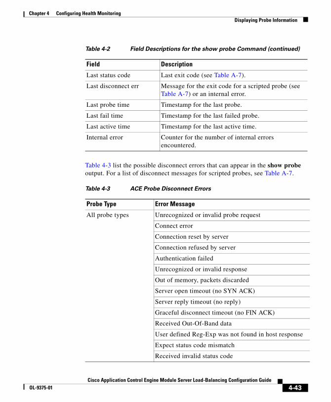
Chapter 4 Configuring Health MonitoringDisplaying Probe Information
Table 4-3 list the possible disconnect errors that can appear in the show probe output. For a list of disconnect messages for scripted probes, see Table A-7.
Last status code Last exit code (see Table A-7).
Last disconnect err Message for the exit code for a scripted probe (see Table A-7) or an internal error.
Last probe time Timestamp for the last probe.
Last fail time Timestamp for the last failed probe.
Last active time Timestamp for the last active time.
Internal error Counter for the number of internal errors encountered.
Table 4-2 Field Descriptions for the show probe Command (continued)
Field Description
Table 4-3 ACE Probe Disconnect Errors
Probe Type Error Message
All probe types Unrecognized or invalid probe request
Connect error
Connection reset by server
Connection refused by server
Authentication failed
Unrecognized or invalid response
Out of memory, packets discarded
Server open timeout (no SYN ACK)
Server reply timeout (no reply)
Graceful disconnect timeout (no FIN ACK)
Received Out-Of-Band data
User defined Reg-Exp was not found in host response
Expect status code mismatch
Received invalid status code
4-43Cisco Application Control Engine Module Server Load-Balancing Configuration Guide
OL-9375-01

Chapter 4 Configuring Health MonitoringDisplaying Probe Information
ICMP ICMP Internal error
ICMP Internal error: Write failure
ICMP Internal error: Received bad FD
Host Unreachable, no route found to destination
ARP not resolved for dest-ip (destination IP address)
Network down
Egress interface has no ip addr (IP address)
ICMP Internal error: Data entry being modified
ICMP Internal error: No space, transmit path is full
ICMP Host unreachable
ICMP Dest unreachable
ICMP Time exceeded
ICMP Redirect
Received ICMP Echo Request
Received ICMP Stale pkt
Unexpected ICMP pkt type received
ICMP Pkt received is too short
ICMP Pkt received is too long
HTTP/HTTPS MD5 mismatch
HTTPS Failed to create SSL context
Internal error: Failed to create SSL session
Invalid server greeting
Internal error: Failed to build a server query
Table 4-3 ACE Probe Disconnect Errors (continued)
Probe Type Error Message
4-44Cisco Application Control Engine Module Server Load-Balancing Configuration Guide
OL-9375-01

Chapter 4 Configuring Health MonitoringDisplaying Probe Information
To display the global statistics for a probe type, use the show stats probe type command in Exec mode. The syntax of this command is:
show stats probe type probe_type
To view a list of probe types, enter:
host1/Admin# show stats probe type ?
For example, to view the global statistics for all DNS probes, enter:
host1/Admin# show stats probe type dns
Table 4-4 describes the fields in the show stats probe type command output.
Table 4-4 Field Descriptions for the show stats probe type command
Field Description
Total probes sent Total number of probes sent.
Total send failures Total number of send failures. These failures are due to internal errors.
Total probes passed Total number of passed probes.
Total probes failed Total number of failed probes.
Total connect errors Total number of connection errors.
Total conns refused Total number of connections refused.
Total RST received Total number of resets received.
Total open timeouts Total number of open timeouts for the specified probe type.
Total receive timeouts Total number of time outs received.
4-45Cisco Application Control Engine Module Server Load-Balancing Configuration Guide
OL-9375-01
Chapter 4 Configuring Health MonitoringClearing Probe Statistics
Clearing Probe StatisticsThis section describes the commands you use to clear probe statistics, either for individual probes or for all probes in a context. It contains the following subsections:
• Clearing Statistics for Individual Probes
• Clearing All Probe Statistics in a Context
Clearing Statistics for Individual ProbesTo clear the statistics displayed through the show probe command for a specific probe, use the clear probe command in Exec mode.The syntax of this command is:
clear probe name
The name argument is the name of a configured probe.
For example, to clear the statistics for the DNS1 probe, enter:
host1/Admin# clear probe DNS1
Note If you have redundancy configured, then you need to explicitly clear load-balancing statistics on both the active and the standby ACEs. Clearing statistics on the active module alone will leave the standby module’s statistics at the old values.
Clearing All Probe Statistics in a ContextTo clear all probe statistics in the current context, use the clear stats probe command in Exec mode. The syntax of this command is:
clear stats probe
For example, enter:
host1/Admin# clear stats probe
4-46Cisco Application Control Engine Module Server Load-Balancing Configuration Guide
OL-9375-01

Chapter 4 Configuring Health MonitoringWhere to Go Next
Note If you have redundancy configured, then you need to explicitly clear load-balancing statistics on both the active and the standby ACEs. Clearing statistics on the active module alone will leave the standby module’s statistics at the old values.
Where to Go NextTo learn how to use the Toolkit Command Language (TCL) to write probe scripts, see Appendix A, Using Toolkit Command Language (TCL) Scripts with the ACE. To configure stickiness (session persistence), see Chapter 5, Configuring Stickiness. To configure firewall load balancing (FWLB), see Chapter 6, Configuring Firewall Load Balancing.
4-47Cisco Application Control Engine Module Server Load-Balancing Configuration Guide
OL-9375-01

Chapter 4 Configuring Health MonitoringWhere to Go Next
4-48Cisco Application Control Engine Module Server Load-Balancing Configuration Guide
OL-9375-01
Cisco Application Control Engine Module Server LOL-9375-01
C H A P T E R 5
Configuring StickinessThis chapter describes how to configure stickiness (sometimes referred to as session persistence) on an Cisco Application Control Engine (ACE) module. It contains the following major sections:
• Overview of Stickiness
• Configuration Requirements and Considerations
• Configuring IP-Address Stickiness
• Configuring HTTP-Cookie Stickiness
• Configuring HTTP-Header Stickiness
• Configuring an SLB Traffic Policy for Stickiness
• Displaying Sticky Configurations and Statistics
• Clearing Sticky Statistics
• Example of a Sticky Configuration
5-1oad-Balancing Configuration Guide
Chapter 5 Configuring StickinessOverview of Stickiness
Overview of StickinessStickiness is an ACE feature that allows the same client to maintain multiple simultaneous or subsequent TCP or IP connections with the same real server for the duration of a session. A session, as used here, is defined as a series of transactions between a client and a server over some finite period of time (from several minutes to several hours). This feature is particularly useful for e-commerce applications where a client needs to maintain multiple connections with the same server while shopping online, especially while building a shopping cart and during the checkout process.
Depending on the configured SLB policy, the ACE “sticks” a client to an appropriate server after the ACE has determined which load-balancing method to use. If the ACE determines that a client is already stuck to a particular server, then the ACE sends that client request to that server, regardless of the load-balancing criteria specified by the matched policy. If the ACE determines that the client is not stuck to a particular server, it applies the normal load balancing rules to the content request.
This section contains the following subsections:
• Why Use Stickiness?
• Sticky Groups
• Sticky Methods
• Sticky Table
• Backup Server Farm Behavior with Stickiness
Why Use Stickiness?When customers visit an e-commerce site, they usually start out by browsing the site, the Internet equivalent of window shopping. Depending on the application, the site may require that the client become “stuck” to one server once the connection is established, or the application may not require this until the client starts to build a shopping cart.
5-2Cisco Application Control Engine Module Server Load-Balancing Configuration Guide
OL-9375-01
Chapter 5 Configuring StickinessOverview of Stickiness
In either case, once the client adds items to the shopping cart, it is important that all of the client requests get directed to the same server so that all the items are contained in one shopping cart on one server. An instance of a customer's shopping cart is typically local to a particular Web server and is not duplicated across multiple servers.
E-commerce applications are not the only types of applications that require stickiness. Any Web application that maintains client information may require stickiness, such as banking applications or online trading. Other uses include FTP and HTTP file transfers.
Sticky GroupsThe ACE uses the concept of sticky groups to configure stickiness. A sticky group allows you to specify sticky attributes. Once you configure a sticky group and its attributes, you associate the sticky group with a match statement or a Layer 7 policy-map action in a Layer 7 SLB policy map. You can create a maximum of 4096 sticky groups in each context. Each sticky group that you configure on the ACE contains a series of parameters that determine:
• Sticky method
• Timeout
• Replication
• Cookie offset and other cookie-related attributes
• HTTP header offset and other header-related attributes
Sticky MethodsBecause an application must distinguish each user or group of users, the ACE needs to determine how a particular user is stuck to a specific Web server. The ACE supports the following sticky methods:
• Source and/or destination IP address
• Cookie
• Hypertext Transfer Protocol (HTTP) header
The e-commerce application itself often dictates which of these methods is appropriate for a particular e-commerce vendor.
5-3Cisco Application Control Engine Module Server Load-Balancing Configuration Guide
OL-9375-01
Chapter 5 Configuring StickinessOverview of Stickiness
This section contains the following subsections:
• IP Address Stickiness
• Cookie Stickiness
• HTTP Header Stickiness
IP Address Stickiness
You can use the source IP address, the destination IP address, or both to uniquely identify individual clients and their requests for stickiness purposes based on their IP netmask. However, if an enterprise or a service provider uses a megaproxy to establish client connections to the Internet, the source IP address no longer is a reliable indicator of the true source of the request. In this case, you can use cookies or one of the other sticky methods to ensure session persistence.
Cookie Stickiness
Client cookies uniquely identify clients to the ACE and the servers providing content. A cookie is a small data structure within the HTTP header that is used by a server to deliver data to a Web client and request that the client store the information. In certain applications, the client returns the information to the server to maintain the connection state or persistence between the client and the server.
When the ACE examines a request for content and determines through policy matching that the content is sticky, it examines any cookie or URL present in the content request. The ACE uses the information in the cookie or URL to direct the content request to the appropriate server. The ACE supports the following types of cookie stickiness:
• Dynamic cookie learning
You can configure the ACE to look for a specific cookie name and automatically learn its value either from the client request HTTP header or from the server Set-Cookie message in the server response. Dynamic cookie learning is useful when dealing with applications that store more than just the session ID or user ID within the same cookie. Only very specific bytes of the cookie value are relevant to stickiness.
5-4Cisco Application Control Engine Module Server Load-Balancing Configuration Guide
OL-9375-01

Chapter 5 Configuring StickinessOverview of Stickiness
By default, the ACE learns the entire cookie value. You can optionally specify an offset and length to instruct the ACE to learn only a portion of the cookie value.
Alternatively, you can specify a secondary cookie value that appears in the URL string in the HTTP request. This option instructs the ACE to search for (and eventually learn or stick to) the cookie information as part of the URL. URL learning is useful with applications that insert cookie information as part of the HTTP URL. In some cases, you can use this feature to work around clients that reject cookies.
• Cookie insert
The ACE inserts the cookie on behalf of the server upon the return request, so that the ACE can perform cookie stickiness even when the servers are not configured to set cookies. The cookie contains information that the ACE uses to ensure persistence to a specific real server.
HTTP Header Stickiness
Additionally, you can use HTTP-header information to provide stickiness. With HTTP header stickiness, you can specify a header offset to provide stickiness based on a unique portion of the HTTP header.
Sticky TableTo keep track of sticky connections, the ACE uses a sticky table. Table entries include the following items:
• Sticky groups
• Sticky methods
• Sticky connections
• Real servers
The sticky table can hold a maximum of four million entries (four million simultaneous users). When the table reaches the maximum number of entries, additional sticky connections cause the table to wrap and the first users become unstuck from their respective servers.
5-5Cisco Application Control Engine Module Server Load-Balancing Configuration Guide
OL-9375-01
Chapter 5 Configuring StickinessOverview of Stickiness
The ACE uses a configurable timeout mechanism to age out sticky table entries. When an entry times out, it becomes eligible for reuse. High connection rates may cause the premature aging out of sticky entries. In this case, the ACE reuses the entries that are closest to expiration first.
Sticky entries can be either dynamic (generated by the ACE on-the-fly) or static (user-configured). When you create a static sticky entry, the ACE places the entry in the sticky table immediately. Static entries remain in the sticky database until you remove them from the configuration. You can create a maximum of 4096 static sticky entries in each context.
If the ACE takes a real server out of service for whatever reason (probe failure, no inservice command, or ARP timeout), the ACE removes from the database any sticky entries that are related to that server.
Backup Server Farm Behavior with StickinessWhen you associate a server farm with a sticky group using the serverfarm command in sticky configuration mode, the primary server farm inherits the stickiness of the sticky group. The ACE sends requests from the same client to the same server in the primary server farm based on the type of stickiness that you configure in the sticky group. If you also configure a backup server farm using the optional backup keyword of the same command, the backup server farm automatically becomes sticky, too, regardless of whether you configure the sticky option or not.
If all the servers in the primary server farm go down, the ACE sends all connections to the backup server farm. When the primary server farm comes back up (that is, at least one server becomes active), existing connections to the backup server farm continue to be serviced by the backup server farm. The ACE also sends new requests for existing sticky connections to the backup server farm.
The ACE sends all new connection requests to the primary server farm. Such requests include those for which there is no entry in the sticky table, the sticky entry aged out, or the ACE overwrote the sticky entry because the sticky table was full.
If you want to configure a sorry server farm and you want existing connections to revert to the primary server farm after it comes back up, do not use stickiness. For details about configuring backup server farms and sorry servers, see Chapter 3, Configuring Traffic Policies for Server Load Balancing.
5-6Cisco Application Control Engine Module Server Load-Balancing Configuration Guide
OL-9375-01
Chapter 5 Configuring StickinessConfiguration Requirements and Considerations
Configuration Requirements and ConsiderationsFor best results, we recommend that you observe the following requirements and considerations when you configure stickiness on your ACE module.
• For each context in which you configure stickiness, you must:
– Configure a resource class in the Admin context that you can associate with one or more contexts where you want to configure stickiness
– Allocate a minimum non-zero percentage of resources to stickiness in the resource class using the limit-resource command
– Associate one or more user contexts with the resource class
For details about configuring resource groups and allocating resources, refer to the Cisco Application Control Engine Module Virtualization Configuration Guide.
• You can configure the same sticky group in multiple policies or virtual servers. In that case, the sticky behavior applies to all connections to any of those policies or class maps. These connections are referred to as buddy connections because, if you configure both policy or class map 1 and 2 with the same sticky group, a client stuck to server A through policy or class map 1 also will be stuck to the same server A through policy or class map 2.
Note You can associate a maximum of 1024 instances of the same type of regular expression (regex) with a a Layer 4 policy map. This limit applies to all Layer 7 policy-map types. You configure regexes in:
• Match statements in Layer 7 class maps
• Inline match statements in Layer 7 policy maps
• Layer 7 hash predictors for server farms
• Layer 7 sticky expressions in sticky groups
5-7Cisco Application Control Engine Module Server Load-Balancing Configuration Guide
OL-9375-01
Chapter 5 Configuring StickinessConfiguring IP-Address Stickiness
Configuring IP-Address StickinessIP address stickiness allows you to stick a client to the same server for multiple subsequent connections as needed to complete a transaction using the client source IP address, the destination IP address, or both. If the service provider or enterprise uses a megaproxy to allow clients to connect to the Internet, use cookies or one of the other sticky methods described in this chapter.
This section contains the following subsections:
• Configuration Requirements and Considerations
• IP-Address Stickiness Configuration Quick Start
• Creating an IP-Address Sticky Group
• Configuring a Timeout for IP-Address Stickiness
• Enabling an IP-Address Sticky Timeout to Override Active Connections
• Enabling the Replication of IP-Address Sticky Table Entries
• Configuring Static IP-Address Sticky Table Entries
• Associating a Server Farm with an IP-Address Sticky Group
IP-Address Stickiness Configuration Quick StartTable 5-1 provides a quick overview of the steps required to configure stickiness on an ACE. Each step includes the CLI command or a reference to the procedure required to complete the task. For a complete description of each feature and all the options associated with the CLI commands, see the sections following Table 5-1.
5-8Cisco Application Control Engine Module Server Load-Balancing Configuration Guide
OL-9375-01

Chapter 5 Configuring StickinessConfiguring IP-Address Stickiness
Table 5-1 IP-Address Stickiness Configuration Quick Start
Task and Command Example
1. If you are operating in multiple contexts, observe the CLI prompt to verify that you are operating in the desired context. If necessary, change to, or directly log in to, the correct context.
host1/Admin# changeto C1host1/C1#
The rest of the examples in this table use the Admin context for illustration purposes, unless otherwise specified. For details on creating contexts, refer to the Cisco Application Control Engine Module Administration Guide.
2. Enter configuration mode.
host1/Admin# config host1/Admin(config)#
3. Ensure that you have configured a resource class, allocated a minimum percentage of resources to stickiness, and associated one or more contexts where you want to configure stickiness with the resource class. See the “Configuration Requirements and Considerations” section. For details about configuring a resources class and allocating resources, refer to the Cisco Application Control Engine Module Virtualization Configuration Guide.
4. Create a sticky-IP group and enter sticky IP configuration mode.
host1/Admin(config)# sticky ip-netmask 255.255.255.0 address both GROUP1host1/Admin(config-sticky-ip)#
5. Configure a timeout for IP address stickiness.
host1/Admin(config-sticky-ip)# timeout 720
6. (Optional) Enable the timeout to override active connections.
host1/Admin(config-sticky-ip)# timeout activeconns
7. Enable the replication of sticky table information to the standby context in case of a switchover in a redundancy configuration. For details about configuring redundancy on an ACE, refer to the Cisco Application Control Engine Module Administration Guide.
host1/Admin(config-sticky-ip)# replicate sticky
5-9Cisco Application Control Engine Module Server Load-Balancing Configuration Guide
OL-9375-01
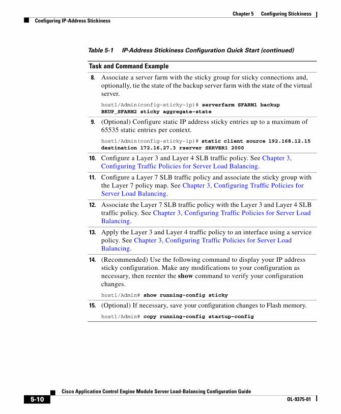
Chapter 5 Configuring StickinessConfiguring IP-Address Stickiness
8. Associate a server farm with the sticky group for sticky connections and, optionally, tie the state of the backup server farm with the state of the virtual server.
host1/Admin(config-sticky-ip)# serverfarm SFARM1 backup BKUP_SFARM2 sticky aggregate-state
9. (Optional) Configure static IP address sticky entries up to a maximum of 65535 static entries per context.
host1/Admin(config-sticky-ip)# static client source 192.168.12.15 destination 172.16.27.3 rserver SERVER1 2000
10. Configure a Layer 3 and Layer 4 SLB traffic policy. See Chapter 3, Configuring Traffic Policies for Server Load Balancing.
11. Configure a Layer 7 SLB traffic policy and associate the sticky group with the Layer 7 policy map. See Chapter 3, Configuring Traffic Policies for Server Load Balancing.
12. Associate the Layer 7 SLB traffic policy with the Layer 3 and Layer 4 SLB traffic policy. See Chapter 3, Configuring Traffic Policies for Server Load Balancing.
13. Apply the Layer 3 and Layer 4 traffic policy to an interface using a service policy. See Chapter 3, Configuring Traffic Policies for Server Load Balancing.
14. (Recommended) Use the following command to display your IP address sticky configuration. Make any modifications to your configuration as necessary, then reenter the show command to verify your configuration changes.
host1/Admin# show running-config sticky
15. (Optional) If necessary, save your configuration changes to Flash memory.
host1/Admin# copy running-config startup-config
Table 5-1 IP-Address Stickiness Configuration Quick Start (continued)
Task and Command Example
5-10Cisco Application Control Engine Module Server Load-Balancing Configuration Guide
OL-9375-01

Chapter 5 Configuring StickinessConfiguring IP-Address Stickiness
Creating an IP-Address Sticky GroupBefore you begin to configure an IP-address sticky group, be sure that you have allocated resources to stickiness as described in the “Configuration Requirements and Considerations” section.
To create a sticky group for IP-address stickiness, use the sticky ip netmask command in configuration mode. You can create a maximum of 4096 sticky groups on an ACE. The full syntax of this command is:
sticky ip-netmask netmask address {source | destination | both} name
The keywords, arguments, and options are:
• ip netmask netmask—Specifies the network mask that the ACE applies to the IP address. Enter a network mask in dotted-decimal notation (for example, 255.255.255.0).
• address—Specifies the IP address used for stickiness. Enter one of the following options after the address keyword:
– source—Specifies that the ACE use the client source IP address to stick the client to a server. You typically use this keyword in Web application environments.
– destination—Specifies that the ACE use the destination address specified in the client request to stick the client to a server. You typically use this keyword in caching environments.
– both—Specifies that the ACE use both the source IP address and the destination IP address to stick the client to a server.
• name—Specifies a unique identifier of the sticky group. Enter an unquoted text string with no spaces and a maximum of 64 alphanumeric characters.
For example, to create a sticky group that uses IP address stickiness based on both the source IP address and the destination IP address, enter:
host1/Admin(config)# sticky ip netmask 255.255.255.0 address both GROUP1host1/Admin(config-sticky-ip)#
To remove the sticky group from the configuration, enter:
host1/Admin(config)# no sticky ip netmask 255.255.255.0 address both GROUP1
5-11Cisco Application Control Engine Module Server Load-Balancing Configuration Guide
OL-9375-01
Chapter 5 Configuring StickinessConfiguring IP-Address Stickiness
Configuring a Timeout for IP-Address StickinessThe sticky timeout specifies the period of time that the ACE keeps (if possible) the IP-address sticky information for a client connection in the sticky table after the latest client connection terminates. The ACE resets the sticky timer for a specific sticky-table entry each time that the module opens a new connection or receives a new HTTP GET on an existing connection matching that entry. High connection rates may cause the premature age-out of sticky table entries.
To configure an IP address sticky timeout, use the timeout minutes command in sticky IP configuration mode. The syntax of this command is:
timeout minutes
For the minutes argument, enter an integer from 1 to 65535. The default is 1440 minutes (24 hours).
For example, enter:
host1/Admin(config-sticky-ip)# timeout 720
To reset the timeout to the default value of 1440 minutes, enter:
host1/Admin(config-sticky-ip)# no timeout 720
Enabling an IP-Address Sticky Timeout to Override Active Connections
By default, the ACE ages out a sticky table entry when the timeout for that entry expires and no active connections matching that entry exist. To specify that the ACE time out IP address sticky table entries even if active connections exist after the sticky timer expires, use the timeout activeconns command in sticky IP configuration mode.
The syntax of this command is:
timeout activeconns
For example, enter:
host1/Admin(config-sticky-ip)# timeout activeconns
5-12Cisco Application Control Engine Module Server Load-Balancing Configuration Guide
OL-9375-01

Chapter 5 Configuring StickinessConfiguring IP-Address Stickiness
To restore the behavior of the ACE to the default of not timing out IP address sticky entries if active connections exist, enter:
host1/Admin(config-sticky-ip)# no timeout activeconns
Enabling the Replication of IP-Address Sticky Table EntriesIf you are using redundancy, you can configure the ACE to replicate IP address sticky table entries on the standby ACE so that, if a switchover occurs, the new active ACE can maintain existing sticky connections. To instruct the ACE to replicate IP address sticky table entries on the standby ACE, use the replicate sticky command in sticky-IP configuration mode. The syntax of this command is:
replicate sticky
Note The timer of an IP address sticky table entry on the standby ACE is reset every time the entry is synchronized with the active ACE entry. Thus, the standby sticky entry may have a lifetime up to twice as long as the active entry. However, if the entry expires on the active ACE or a new real server is selected and a new entry is created, the old entry on the standby ACE is replaced.
For example, enter:
host1/Admin(config-sticky-ip)# replicate sticky
To restore the default behavior of the ACE to not replicating IP address sticky table entries, enter:
host1/Admin(config-sticky-ip)# no replicate sticky
5-13Cisco Application Control Engine Module Server Load-Balancing Configuration Guide
OL-9375-01

Chapter 5 Configuring StickinessConfiguring IP-Address Stickiness
Configuring Static IP-Address Sticky Table EntriesYou can configure static sticky table entries based on the source IP address, destination IP address, or real server name and port. Static sticky-IP values remain constant over time and you can configure multiple static entries.
Note When you configure a static entry, the ACE enters it into the sticky table immediately. You can create a maximum of 4096 static entries.
To configure static sticky-IP table entries, use the static client command in sticky-IP configuration mode. The syntax of this command varies according to the address option you chose when you created the sticky group. See the “Creating an IP-Address Sticky Group” section.
If you configured the sticky group with the source option, the syntax of this command is:
static client source ip_address rserver name [number]
If you configured the sticky group with the destination option, the syntax of this command is:
static client destination ip_address rserver name [number]
If you configured the sticky group with the both option, the syntax of this command is:
static client source ip_address [destination ip_address]{rserver name [number]}
The keywords, arguments, and options are:
• source ip_address—Specifies that the static entry be based on the source IP address. Enter an IP address in dotted decimal notation (for example, 192.168.12.15).
• destination ip_address—Specifies that the static entry be based on the destination IP address. Enter an IP address in dotted-decimal notation (for example, 172.16.27.3).
5-14Cisco Application Control Engine Module Server Load-Balancing Configuration Guide
OL-9375-01

Chapter 5 Configuring StickinessConfiguring IP-Address Stickiness
• rserver name—Specifies that the static entry be based on the real server name. Enter the name of an existing real server as an unquoted text string with no spaces and a maximum of 64 characters.
• number—(Optional) Port number of the real server. Enter an integer from 1 to 65535.
For example, to configure a static sticky entry based on the source IP address, the destination IP address, and the server name and port number, enter:
host1/Admin(config-sticky-ip)# static client source 192.168.12.15 destination 172.16.27.3 rserver SERVER1 2000
To remove the static entry from the sticky table, enter:
host1/Admin(config-sticky-ip)# no static client source 192.168.12.15 destination 172.16.27.3 rserver SERVER1 2000
Associating a Server Farm with an IP-Address Sticky GroupTo complete a sticky group configuration, you must configure a server-farm entry for the group. To configure a server-farm entry for a sticky group, use the serverfarm command in sticky-IP configuration mode. The syntax of this command is:
serverfarm name1 [backup name2 [sticky] [aggregate-state]]
The keywords, arguments, and options are:
• name1—Identifier of an existing serverfarm that you want to associate with the sticky group. You can associate one serverfarm with each sticky group.
• backup name2—(Optional) Specifies an identifier of an existing server farm that you want the ACE to use as a backup server farm. If the primary server farm goes down, the ACE uses the configured backup server farm. Once clients are stuck to a backup server farm, they remain stuck to the backup even if the primary server farm becomes active again. For more information about backup server farms, see the “Backup Server Farm Behavior with Stickiness” section.
5-15Cisco Application Control Engine Module Server Load-Balancing Configuration Guide
OL-9375-01

Chapter 5 Configuring StickinessConfiguring HTTP-Cookie Stickiness
• sticky—(Optional) Specifies that the backup server farm is sticky. If all real servers in the primary server farm go down, the ACE sends all connections to the backup server farm. If at least one real server returns to service in the primary server farm, the backup server farm continues to service existing connections and new requests over existing sticky connections. The ACE sends all new connection requests to the primary server farm.
• aggregate-state—(Optional, but recommended) Specifies that the state of the primary server farm is tied to the state of all the real servers in that server farm and in the backup server farm, if configured. The ACE declares the primary server farm down if all real servers in the primary server farm and all real servers in the backup server farm are down.
For example, to associate a server farm with a sticky group and specify a sticky backup server farm, enter:
host1/Admin(config-sticky-ip)# serverfarm SFARM1 backup BKUP_SFARM2 sticky aggregate-state
To disassociate a server farm from a sticky group, enter:
host1/Admin(config-sticky-ip)# no serverfarm
Configuring HTTP-Cookie StickinessThis section describes how to configure stickiness based on HTTP cookies. The ACE learns cookie values from the:
• HTTP header in the client request
• Set-Cookie message sent by the server to the client
• URL for a Web page
When a client makes an HTTP request to a server, the server typically sends a cookie in the Set-Cookie message in the response to the client. In most cases, the client returns the same cookie value in a subsequent HTTP request. The ACE sticks the client to the same server based on that matching value. This scenario is typical on the Web with traditional Web clients.
However, in some environments, it is common for clients to be unable to support cookies in their browser, which makes this type of cookie sticky connection impossible. To circumvent this problem, the ACE can extract the cookie name and value embedded in the URL string. This feature works only if the server embeds the cookie into the URL link on the web page.
5-16Cisco Application Control Engine Module Server Load-Balancing Configuration Guide
OL-9375-01

Chapter 5 Configuring StickinessConfiguring HTTP-Cookie Stickiness
Depending on client and server behavior and the sequence of frames, the same cookie value may appear in the standard HTTP cookie that is present in the HTTP header, Set-Cookie message, or cookie embedded in a URL. The actual name of the cookie may differ depending on whether the cookie is embedded in a URL or appears in an HTTP header. The use of a different name for the cookie and the URL occurs because these two parameters are configurable on the server and are often set differently. For example, the set-cookie name may be:
Set-Cookie: session_cookie = 123
The URL may be:
http://www.example.com/?session-id=123
If the client request does not contain a cookie, the ACE looks for the session ID string (?session-id=) configured on the ACE. The value associated with this string is the session ID number that the ACE looks for in the cache. The ACE matches the session ID with the server where the requested information resides and the ACE sends the client request to that server.
The name argument in the sticky command specifies the cookie name that appears in the HTTP header. The name argument in the cookie secondary command specifies the cookie name that appears in the URL.
By default, the maximum number of bytes that the ACE parses to check for a cookie, HTTP header, or URL is 2048. If a cookie, HTTP header, or URL exceeds the default value, the ACE drops the packet and sends a RST (reset) to the client browser. You can increase the number of bytes that the ACE parses using the set header-maxparse-length command in HTTP parameter-map configuration mode. For details about setting the maximum parse length, see Chapter 3, Configuring Traffic Policies for Server Load Balancing.
You can also change the default behavior of the ACE when a cookie, header, or URL exceeds the maximum parse length using the length-exceed command in HTTP parameter-map configuration mode. For details, see Chapter 3, Configuring Traffic Policies for Server Load Balancing.
5-17Cisco Application Control Engine Module Server Load-Balancing Configuration Guide
OL-9375-01

Chapter 5 Configuring StickinessConfiguring HTTP-Cookie Stickiness
Note You can associate a maximum of 1024 instances of the same type of regular expression (regex) with a a Layer 4 policy map. This limit applies to all Layer 7 policy-map types. You configure regexes in:
• Match statements in Layer 7 class maps
• Inline match statements in Layer 7 policy maps
• Layer 7 hash predictors for server farms
• Layer 7 sticky expressions in sticky groups
This section contains the following subsections:
• HTTP-Cookie Stickiness Configuration Quick Start
• Configuring a Cookie Sticky Timeout
• Enabling a Sticky Cookie Timeout to Override Active Connections
• Enabling the Replication of Cookie Sticky Entries
• Enabling Cookie Insertion
• Configuring the Offset and Length of an HTTP Cookie
• Configuring a Secondary Cookie
• Configuring a Static Cookie
5-18Cisco Application Control Engine Module Server Load-Balancing Configuration Guide
OL-9375-01

Chapter 5 Configuring StickinessConfiguring HTTP-Cookie Stickiness
HTTP-Cookie Stickiness Configuration Quick StartTable 5-2 provides a quick overview of the steps required to configure stickiness on an ACE. Each step includes the CLI command or a reference to the procedure required to complete the task. For a complete description of each feature and all the options associated with the CLI commands, see the sections following Table 5-2.
Table 5-2 HTTP Cookie Stickiness Configuration Quick Start
Task and Command Example
1. If you are operating in multiple contexts, observe the CLI prompt to verify that you are operating in the desired context. If necessary, change to, or directly log in to, the correct context.
host1/Admin# changeto C1host1/C1#
The rest of the examples in this table use the Admin context for illustration purposes, unless otherwise specified. For details on creating contexts, refer to the Cisco Application Control Engine Module Administration Guide.
2. Enter configuration mode.
host1/Admin# config host1/Admin(config)#
3. Ensure that you have configured a resource class, allocated a minimum percentage of resources to stickiness, and associated one or more contexts where you want to configure stickiness with the resource class. See the “Configuration Requirements and Considerations” section. For details about configuring a resources class and allocating resources, refer to the Cisco Application Control Engine Module Virtualization Configuration Guide.
4. Create an HTTP cookie sticky group and enter sticky-cookie configuration mode.
host1/Admin(config)# sticky http-cookie cisco.com GROUP2host1/Admin(config-sticky-cookie)#
5. Configure a timeout for HTTP-cookie stickiness.
host1/Admin(config-sticky-cookie)# timeout 720
5-19Cisco Application Control Engine Module Server Load-Balancing Configuration Guide
OL-9375-01
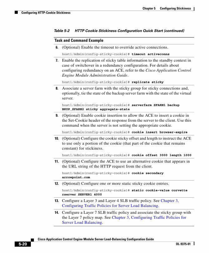
Chapter 5 Configuring StickinessConfiguring HTTP-Cookie Stickiness
6. (Optional) Enable the timeout to override active connections.
host1/Admin(config-sticky-cookie)# timeout activeconns
7. Enable the replication of sticky table information to the standby context in case of switchover in a redundancy configuration. For details about configuring redundancy on an ACE, refer to the Cisco Application Control Engine Module Administration Guide.
host1/Admin(config-sticky-cookie)# replicate sticky
8. Associate a server farm with the sticky group for sticky connections and, optionally, tie the state of the backup server farm with the state of the virtual server.
host1/Admin(config-sticky-cookie)# serverfarm SFARM1 backup BKUP_SFARM2 sticky aggregate-state
9. (Optional) Enable cookie insertion to allow the ACE to insert a cookie in the Set-Cookie header of the response from the server to the client. Use this command when the server is not setting the appropriate cookie.
host1/Admin(config-sticky-cookie)# cookie insert browser-expire
10. (Optional) Configure the cookie sticky offset and length to instruct the ACE to use only a portion of the cookie (that part of the cookie that remains constant) for stickiness.
host1/Admin(config-sticky-cookie)# cookie offset 3000 length 1000
11. (Optional) Configure the ACE to use an alternative cookie that appears in the URL string of the HTTP request from the client.
host1/Admin(config-sticky-cookie)# cookie secondary arrowpoint.com
12. (Optional) Configure one or more static sticky cookie entries.
host1/Admin(config-sticky-cookie)# static cookie-value corvette rserver SERVER1 4000
13. Configure a Layer 3 and Layer 4 SLB traffic policy. See Chapter 3, Configuring Traffic Policies for Server Load Balancing.
14. Configure a Layer 7 SLB traffic policy and associate the sticky group with the Layer 7 policy map. See Chapter 3, Configuring Traffic Policies for Server Load Balancing.
Table 5-2 HTTP Cookie Stickiness Configuration Quick Start (continued)
Task and Command Example
5-20Cisco Application Control Engine Module Server Load-Balancing Configuration Guide
OL-9375-01
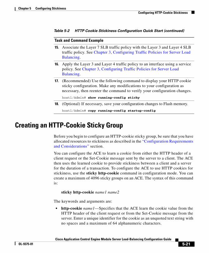
Chapter 5 Configuring StickinessConfiguring HTTP-Cookie Stickiness
Creating an HTTP-Cookie Sticky GroupBefore you begin to configure an HTTP-cookie sticky group, be sure that you have allocated resources to stickiness as described in the “Configuration Requirements and Considerations” section.
You can configure the ACE to learn a cookie from either the HTTP header of a client request or the Set-Cookie message sent by the server to a client. The ACE then uses the learned cookie to provide stickiness between a client and a server for the duration of a transaction. To configure the ACE to use HTTP cookies for stickiness, use the sticky http-cookie command in configuration mode. You can create a maximum of 4096 sticky groups on an ACE. The syntax of this command is:
sticky http-cookie name1 name2
The keywords and arguments are:
• http-cookie name1—Specifies that the ACE learn the cookie value from the HTTP header of the client request or from the Set-Cookie message from the server. Enter a unique identifier for the cookie as an unquoted text string with no spaces and a maximum of 64 alphanumeric characters.
15. Associate the Layer 7 SLB traffic policy with the Layer 3 and Layer 4 SLB traffic policy. See Chapter 3, Configuring Traffic Policies for Server Load Balancing.
16. Apply the Layer 3 and Layer 4 traffic policy to an interface using a service policy. See Chapter 3, Configuring Traffic Policies for Server Load Balancing.
17. (Recommended) Use the following command to display your HTTP cookie sticky configuration. Make any modifications to your configuration as necessary, then reenter the command to verify your configuration changes.
host1/Admin# show running-config sticky
18. (Optional) If necessary, save your configuration changes to Flash memory.
host1/Admin# copy running-config startup-config
Table 5-2 HTTP Cookie Stickiness Configuration Quick Start (continued)
Task and Command Example
5-21Cisco Application Control Engine Module Server Load-Balancing Configuration Guide
OL-9375-01
Chapter 5 Configuring StickinessConfiguring HTTP-Cookie Stickiness
• name2—Specifies the unique identifier of the sticky group. Enter an unquoted text string with no spaces and a maximum of 64 alphanumeric characters.
For example, to create a sticky group for cookie stickiness, enter:
host1/Admin(config)# sticky http-cookie cisco.com GROUP3host1/Admin(config-sticky-cookie)#
To remove the sticky group from the configuration, enter:
host1/Admin(config)# no sticky http-cookie cisco.com GROUP3
Configuring a Cookie Sticky TimeoutThe sticky timeout specifies the period of time that the ACE keeps the HTTP-cookie sticky information for a client connection in the sticky table after the latest client connection terminates. The ACE resets the sticky timer for a specific sticky-table entry each time that the module opens a new connection matching that entry.
Note The total sticky timeout is equal to the current time plus the timeout interval that you configure plus an internal update interval. The update interval can vary from 10 to 30 minutes depending on when you configured the sticky timeout and when the timeout update process reaches the particular sticky entry in the table.
To configure a sticky timeout, use the timeout minutes command in sticky-cookie configuration mode. The syntax of this command is:
timeout minutes
For the minutes argument, enter an integer from 1 to 65535. The default is 1440 minutes (24 hours).
For example, enter:
host1/Admin(config-sticky-cookie)# timeout 720
To reset the timeout to the default value of 1440 minutes, enter:
host1/Admin(config-sticky-cookie)# no timeout 720
5-22Cisco Application Control Engine Module Server Load-Balancing Configuration Guide
OL-9375-01

Chapter 5 Configuring StickinessConfiguring HTTP-Cookie Stickiness
Enabling a Sticky Cookie Timeout to Override Active ConnectionsTo specify that the ACE time out HTTP-cookie sticky table entries even if active connections exist after the sticky timer expires, use the timeout activeconns command in sticky-cookie configuration mode. The syntax of this command is:
timeout activeconns
For example, enter:
host1/Admin(config-sticky-cookie)# timeout activeconns
To restore the behavior of the ACE to the default of not timing out HTTP-cookie sticky entries if active connections exist for those entries, enter:
host1/Admin(config-sticky-cookie)# no timeout activeconns
Enabling the Replication of Cookie Sticky EntriesIf you are using redundancy, you can configure the ACE to replicate HTTP-cookie sticky table entries on the standby ACE so that, if a switchover occurs, the new active ACE can maintain existing sticky connections. To instruct the ACE to replicate sticky table entries on the standby ACE, use the replicate sticky command in sticky-cookie configuration mode. The syntax of this command is:
replicate sticky
Note The timer of a sticky table entry on the standby ACE is reset every time the entry is synchronized with the active ACE entry. Thus, the standby sticky entry may have a lifetime up to twice as long as the active entry. However, if the entry expires on the active ACE or a new real server is selected and a new entry is created, the old entry on the standby ACE is replaced.
For example, enter:
host1/Admin(config-sticky-cookie)# replicate sticky
To restore the default behavior of the ACE to not replicating sticky table entries, enter:
host1/Admin(config-sticky-cookie)# no replicate sticky
5-23Cisco Application Control Engine Module Server Load-Balancing Configuration Guide
OL-9375-01

Chapter 5 Configuring StickinessConfiguring HTTP-Cookie Stickiness
Enabling Cookie InsertionUse cookie insertion when you want to use a session cookie for persistence if the server is not currently setting the appropriate cookie. With this feature enabled, the ACE inserts the cookie in the Set-Cookie header of the response from the server to the client. The ACE selects a cookie value that identifies the original server from which the client received a response. For subsequent connections of the same transaction, the client uses the cookie to stick to the same server.
Note With either TCP server reuse or persistence rebalance enabled, the ACE inserts a cookie in every client request. For information about TCP server reuse, see the “Configuring TCP Server Reuse” section in Chapter 3, Configuring Traffic Policies for Server Load Balancing. For information about persistence rebalance, see “Enabling HTTP Persistence Rebalance” in Chapter 3, Configuring Traffic Policies for Server Load Balancing.
To enable cookie insertion, use the cookie insert command in sticky-cookie configuration mode. The syntax of this command is:
cookie insert [browser-expire]
The browser-expire option allows the client’s browser to expire a cookie when the session ends.
For example, to enable cookie insertion and allow a browser to expire the cookie, enter:
host1/Admin(config-sticky-cookie)# cookie insert browser-expire
To disable cookie insertion, enter:
host1/Admin(config-sticky-cookie)# no cookie insert browser-expire
Configuring the Offset and Length of an HTTP CookieAn HTTP-cookie value may change over time with only a portion remaining constant throughout a transaction between the client and a server. You can configure the ACE to use the constant portion of a cookie to make persistent connections to a specific server. To define the portion of the cookie that you want the ACE to use, you specify cookie offset and length values. The ACE stores these values in the sticky table.
5-24Cisco Application Control Engine Module Server Load-Balancing Configuration Guide
OL-9375-01

Chapter 5 Configuring StickinessConfiguring HTTP-Cookie Stickiness
To configure the cookie offset and length, use the cookie offset command in sticky-cookie configuration mode. The syntax of this command is:
cookie offset number1 length number2
The keywords and arguments are:
• offset number1—Specifies the portion of the cookie that the ACE uses to stick the client on a particular server by indicating the bytes to ignore starting with the first byte of the cookie. Enter an integer from 0 to 999. The default is 0, which indicates that the ACE does not exclude any portion of the cookie.
• length number2—Specifies the length of the portion of the cookie (starting with the byte after the offset value) that the ACE uses for sticking the client to the server. Enter an integer from 1 to 1000. The default is 1000.
For example, enter:
host1/Admin(config-sticky-cookie)# cookie offset 500 length 1000
To remove the cookie offset and length from the configuration, enter:
host1/Admin(config-sticky-cookie)# no cookie offset
Configuring a Secondary CookieYou can configure an alternative cookie name that appears in the URL string of the Web page on the server. The ACE uses this cookie to maintain a sticky connection between a client and a server and adds a secondary entry in the sticky table. To configure a secondary cookie, use the cookie secondary command in sticky-cookie configuration mode. The syntax of this command is:
cookie secondary name
Enter a cookie name as an unquoted text string with no spaces and a maximum of 64 characters.
For example, enter:
host1/Admin(config-sticky-cookie)# cookie secondary mysite.com
To remove a secondary cookie from the configuration, enter:
host1/Admin(config-sticky-cookie)# no cookie secondary mysite.com
5-25Cisco Application Control Engine Module Server Load-Balancing Configuration Guide
OL-9375-01
Chapter 5 Configuring StickinessConfiguring HTTP-Cookie Stickiness
Configuring a Static CookieYou can configure the ACE to use static cookies from entries based on cookie values and, optionally, real server names and ports. Static cookie values remain constant over time. You can configure multiple static cookie entries, but there can exist only one unique real-server name for a given static cookie value.
Note When you configure a static entry, the ACE enters it into the sticky table immediately. You can create a maximum of 4096 static entries.
To configure a static cookie, use the static cookie-value command in sticky-cookie configuration mode. The syntax of this command is:
static cookie-value value rserver name [number]
Note You can associate a maximum of 1024 instances of the same type of regular expression (regex) with a a Layer 4 policy map. This limit applies to all Layer 7 policy-map types. You configure regexes in:
• Match statements in Layer 7 class maps
• Inline match statements in Layer 7 policy maps
• Layer 7 hash predictors for server farms
• Layer 7 sticky expressions in sticky groups
The keywords, arguments, and options of this command are:
• value—Cookie string value. Enter an unquoted text string with no spaces and a maximum of 255 alphanumeric characters. Alternatively, you can enter a text string with spaces provided that you enclose the string in quotation marks (“).
• rserver name—Host name of an existing real server.
• number—(Optional) Port number of the real server. Enter an integer from 1 to 65535.
5-26Cisco Application Control Engine Module Server Load-Balancing Configuration Guide
OL-9375-01
Chapter 5 Configuring StickinessConfiguring HTTP-Cookie Stickiness
For example, enter:
host1/Admin(config-sticky-cookie)# static cookie-value CORVETTE rserver SERVER1 4000
To remove a static cookie form the configuration, enter:
host1/Admin(config-sticky-cookie)# no static cookie-value CORVETTE rserver SERVER1 4000
Associating a Server Farm with an HTTP-Cookie Sticky GroupTo complete a sticky group configuration, you must configure a server farm entry for the group. To configure a serverfarm entry for a sticky group, use the serverfarm command in sticky-IP configuration mode. The syntax of this command is:
serverfarm name1 [backup name2 [sticky] [aggregate-state]]
The keywords, arguments, and options are:
• name1—Identifier of an existing serverfarm that you want to associate with the sticky group. You can associate one serverfarm with each sticky group.
• backup name2—(Optional) Specifies an identifier of an existing server farm that you want the ACE to use as a backup server farm. If the primary server farm goes down, the ACE uses the configured backup server farm. Once clients are stuck to a backup server farm, they remain stuck to the backup even if the primary server farm becomes active again. For more information about backup server farms, see the “Backup Server Farm Behavior with Stickiness” section.
• sticky—(Optional) Specifies that the backup server farm is sticky.
• aggregate-state—(Optional, but recommended) Specifies that the state of the primary server farm is tied to the state of all the real servers in that server farm and in the backup server farm, if configured. The ACE declares the primary server farm down if all real servers in the primary server farm and all real servers in the backup server farm are down.
For example, to associate a server farm with a sticky group and specify a sticky backup server farm, enter:
host1/Admin(config-sticky-cookie)# serverfarm SFARM1 backup BKUP_SFARM2 sticky aggregate-state
5-27Cisco Application Control Engine Module Server Load-Balancing Configuration Guide
OL-9375-01
Chapter 5 Configuring StickinessConfiguring HTTP-Header Stickiness
To disassociate a server farm from a sticky group, enter:
host1/Admin(config-sticky-cookie)# no serverfarm
Configuring HTTP-Header StickinessWhen a client requests a URL from a server, the client sends an HTTP request to the ACE. The HTTP request contains a header that contains fields that the ACE can use to provide stickiness. This process ensures that connections from the same client that match the same SLB policy use the same server for subsequent connections based on the HTTP header. You can specify any header name or select from one of the standard HTTP headers.
By default, the ACE CLI is case sensitive. For example, the ACE treats the sticky group names http_sticky_group1 and HTTP_STICKY_GROUP1 as two different group names. You can configure the CLI to be case insensitive for all HTTP-related parameters by entering the case-insensitive command in an HTTP parameter map and then associating the parameter map with a Layer 3 and Layer 4 SLB policy map. For details, see “Configuring an HTTP Parameter Map” section in Chapter 3, Configuring Traffic Policies for Server Load Balancing.
By default, the maximum number of bytes that the ACE parses to check for a cookie, HTTP header, or URL is 2048. If a cookie, HTTP header, or URL exceeds the default value, the ACE drops the packet and sends a RST (reset) to the client browser. You can increase the number of bytes that the ACE parses using the set header-maxparse-length command in HTTP parameter-map configuration mode. For details about setting the maximum parse length, see Chapter 3, Configuring Traffic Policies for Server Load Balancing.
You can also change the default behavior of the ACE when a cookie, header, or URL exceeds the maximum parse length using the length-exceed command in HTTP parameter-map configuration mode. For details, see Chapter 3, Configuring Traffic Policies for Server Load Balancing.
5-28Cisco Application Control Engine Module Server Load-Balancing Configuration Guide
OL-9375-01

Chapter 5 Configuring StickinessConfiguring HTTP-Header Stickiness
Note You can associate a maximum of 1024 instances of the same type of regular expression (regex) with a a Layer 4 policy map. This limit applies to all Layer 7 policy-map types. You configure regexes in:
• Match statements in Layer 7 class maps
• Inline match statements in Layer 7 policy maps
• Layer 7 hash predictors for server farms
• Layer 7 sticky expressions in sticky groups
This section contains the following subsections:
• HTTP-Header Stickiness Configuration Quick Start
• Creating an HTTP-Header Sticky Group
• Configuring a Timeout for HTTP-Header Stickiness
• Enabling an HTTP-Header Sticky Timeout to Override Active Connections
• Enabling the Replication of HTTP-Header Sticky Entries
• Configuring the Offset and Length of the HTTP-Header
• Configuring a Static HTTP-Header Sticky Entry
HTTP-Header Stickiness Configuration Quick StartTable 5-3 provides a quick overview of the steps required to configure stickiness on an ACE. Each step includes the CLI command or a reference to the procedure required to complete the task. For a complete description of each feature and all the options associated with the CLI commands, see the sections following Table 5-3.
5-29Cisco Application Control Engine Module Server Load-Balancing Configuration Guide
OL-9375-01

Chapter 5 Configuring StickinessConfiguring HTTP-Header Stickiness
Table 5-3 HTTP-Header Stickiness Configuration Quick Start
Task and Command Example
1. If you are operating in multiple contexts, observe the CLI prompt to verify that you are operating in the desired context. If necessary, change to, or directly log in to, the correct context.
host1/Admin# changeto C1host1/C1#
The rest of the examples in this table use the Admin context for illustration purposes, unless otherwise specified. For details on creating contexts, refer to the Cisco Application Control Engine Module Administration Guide.
2. Enter configuration mode.
host1/Admin# config host1/Admin(config)#
3. Ensure that you have configured a resource class, allocated a minimum percentage of resources to stickiness, and associated one or more contexts where you want to configure stickiness with the resource class. See the “Configuration Requirements and Considerations” section. For details about configuring a resources class and allocating resources, refer to the Cisco Application Control Engine Module Virtualization Configuration Guide.
4. Create an HTTP-header sticky group and enter sticky-header configuration mode.
host1/Admin(config)# sticky http-header Host GROUP4host1/Admin(config-sticky-header)#
5. Configure a timeout for HTTP-header stickiness.
host1/Admin(config-sticky-header)# timeout 720
6. (Optional) Enable the timeout to override active connections.
host1/Admin(config-sticky-header)# timeout activeconns
7. Enable the replication of HTTP-header sticky table information to the standby context in case of a switchover. Use this command with redundancy. For details about configuring redundancy on an ACE, refer to the Cisco Application Control Engine Module Administration Guide.
host1/Admin(config-sticky-header)# replicate sticky
5-30Cisco Application Control Engine Module Server Load-Balancing Configuration Guide
OL-9375-01

Chapter 5 Configuring StickinessConfiguring HTTP-Header Stickiness
8. Associate a server farm with the sticky group for sticky connections and, optionally, tie the state of the backup server farm with the state of the virtual server.
host1/Admin(config-sticky-ssl)# serverfarm SFARM1 backup BKUP_SFARM2 sticky aggregate-state
9. (Optional) Configure the HTTP-header sticky offset and length to instruct the ACE to use only a portion of the header (that part of the header that remains constant) for stickiness.
host1/Admin(config-sticky-header)# header offset 3000 length 1000
10. (Optional) Configure one or more static HTTP-header sticky entries.
host1/Admin(config-sticky-header)# static header Host rserver SERVER1 4000
11. Configure a Layer 3 and Layer 4 SLB traffic policy. See Chapter 3, Configuring Traffic Policies for Server Load Balancing.
12. Configure a Layer 7 SLB traffic policy and associate the sticky group with the Layer 7 policy map. See Chapter 3, Configuring Traffic Policies for Server Load Balancing.
13. Associate the Layer 7 SLB traffic policy with the Layer 3 and Layer 4 SLB traffic policy. See Chapter 3, Configuring Traffic Policies for Server Load Balancing.
14. Apply the Layer 3 and Layer 4 traffic policy to an interface using a service policy. See Chapter 3, Configuring Traffic Policies for Server Load Balancing.
15. (Recommended) Use the following command to display your HTTP-header sticky configuration. Make any modifications to your configuration as necessary, then reenter the command to verify your configuration changes.
host1/Admin# show running-config sticky
16. (Optional) If necessary, save your configuration changes to Flash memory.
host1/Admin# copy running-config startup-config
Table 5-3 HTTP-Header Stickiness Configuration Quick Start (continued)
Task and Command Example
5-31Cisco Application Control Engine Module Server Load-Balancing Configuration Guide
OL-9375-01

Chapter 5 Configuring StickinessConfiguring HTTP-Header Stickiness
Creating an HTTP-Header Sticky GroupBefore you begin to configure an HTTP-header sticky group, be sure that you have allocated resources to stickiness as described in the “Configuration Requirements and Considerations” section.
To create an HTTP-header sticky group to enable the ACE to stick client connections to the same real server based on HTTP headers, use the sticky http-header command in configuration mode. You can create a maximum of 4096 sticky groups on an ACE. The syntax of this command is:
sticky http-header name1 name2
The keywords and arguments are:
• http-header name1—Specifies stickiness based on the HTTP header. Enter an HTTP header name as an unquoted text string with no spaces and a maximum of 64 alphanumeric characters. Alternatively, you can select one of the standard HTTP headers listed below. For a list and description of the standard HTTP header, see Table 5-4.
Table 5-4 Standard HTTP Header Fields
Field Name Description
Accept A semicolon-separated list of representation schemes (content type meta information values) that will be accepted in the response to the request.
Accept-Charset The character sets are acceptable for the response. This field allows clients capable of understanding more comprehensive or special-purpose character sets to signal that capability to a server that can represent documents in those character sets.
Accept-Encoding Restricts the content encoding that a user will accept from the server.
Accept-Language The ISO code for the language in which the document is written. The language code is an ISO 3316 language code with an optional ISO639 country code to specify a national variant.
5-32Cisco Application Control Engine Module Server Load-Balancing Configuration Guide
OL-9375-01

Chapter 5 Configuring StickinessConfiguring HTTP-Header Stickiness
Authorization Specifies that the user agent wants to authenticate itself with a server, usually after receiving a 401 response.
Cache-Control Directives that must be obeyed by all caching mechanisms along the request/response chain. The directives specify behavior intended to prevent caches from adversely interfering with the request or response.
Connection Allows the sender to specify connection options.
Content-MD5 An MD5 digest of the entity-body that provides an end-to-end integrity check. Only a client or an origin server can generate this header field.
Expect Used by a client to inform the server about what behaviors the client requires.
From Contains the e-mail address of the person that controls the requesting user agent.
Host The Internet host and port number of the resource being requested, as obtained from the original URI given by the user or referring resource. The Host field value MUST represent the naming authority of the origin server or gateway given by the original URL.
If-Match Used with a method to make it conditional. A client that has one or more entities previously obtained from the resource can verify that one of those entities is current by including a list of their associated entity tags in the If-Match header field. The purpose of this feature is to allow efficient updates of cached information with a minimum amount of transaction overhead. It is also used, on updating requests, to prevent inadvertent modification of the wrong version of a resource. As a special case, the value “*” matches any current entity of the resource.
Table 5-4 Standard HTTP Header Fields (continued)
Field Name Description
5-33Cisco Application Control Engine Module Server Load-Balancing Configuration Guide
OL-9375-01
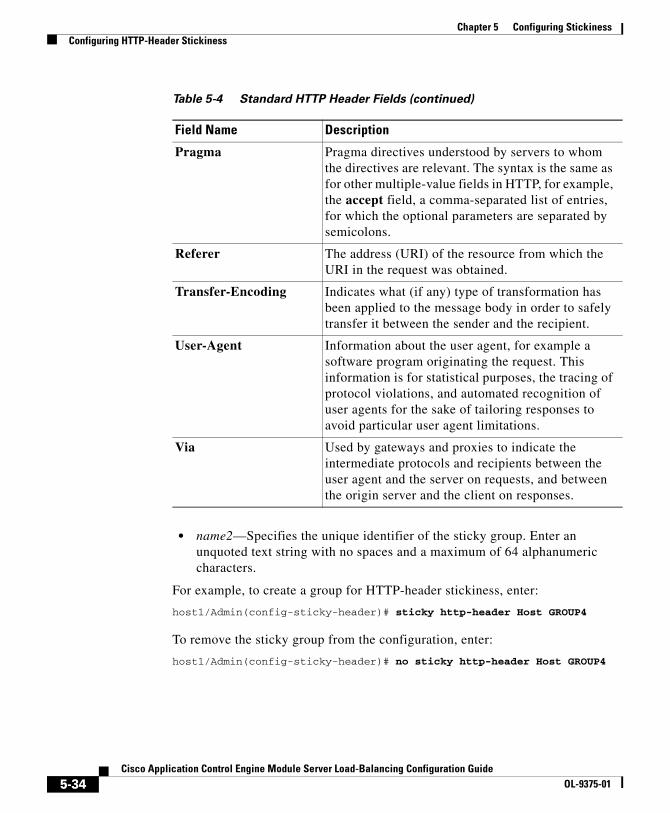
Chapter 5 Configuring StickinessConfiguring HTTP-Header Stickiness
• name2—Specifies the unique identifier of the sticky group. Enter an unquoted text string with no spaces and a maximum of 64 alphanumeric characters.
For example, to create a group for HTTP-header stickiness, enter:
host1/Admin(config-sticky-header)# sticky http-header Host GROUP4
To remove the sticky group from the configuration, enter:
host1/Admin(config-sticky-header)# no sticky http-header Host GROUP4
Pragma Pragma directives understood by servers to whom the directives are relevant. The syntax is the same as for other multiple-value fields in HTTP, for example, the accept field, a comma-separated list of entries, for which the optional parameters are separated by semicolons.
Referer The address (URI) of the resource from which the URI in the request was obtained.
Transfer-Encoding Indicates what (if any) type of transformation has been applied to the message body in order to safely transfer it between the sender and the recipient.
User-Agent Information about the user agent, for example a software program originating the request. This information is for statistical purposes, the tracing of protocol violations, and automated recognition of user agents for the sake of tailoring responses to avoid particular user agent limitations.
Via Used by gateways and proxies to indicate the intermediate protocols and recipients between the user agent and the server on requests, and between the origin server and the client on responses.
Table 5-4 Standard HTTP Header Fields (continued)
Field Name Description
5-34Cisco Application Control Engine Module Server Load-Balancing Configuration Guide
OL-9375-01
Chapter 5 Configuring StickinessConfiguring HTTP-Header Stickiness
Configuring a Timeout for HTTP-Header StickinessThe sticky timeout specifies the period of time that the ACE keeps the HTTP-header sticky information for a client connection in the sticky table after the latest client connection terminates. The ACE resets the sticky timer for a specific sticky-table entry each time that the module opens a new connection matching that entry.
To configure a sticky timeout, use the timeout command in sticky-header configuration mode. The syntax of this command is:
timeout minutes
For the minutes argument, enter an integer from 1 to 65535. The default is 1440 minutes (24 hours).
For example, enter:
host1/Admin(config-sticky-header)# timeout 720
To reset the timeout to the default value of 1440 minutes, enter:
host1/Admin(config-sticky-header)# no timeout 720
Enabling an HTTP-Header Sticky Timeout to Override Active Connections
To specify that the ACE time out HTTP-header sticky table entries even if active connections exist after the sticky timer expires, use the timeout activeconns command in sticky-header configuration mode. The syntax of this command is:
timeout activeconns
Note The timer of a sticky table entry on the standby ACE is reset every time the entry is synchronized with the active ACE entry. Thus, the standby sticky entry may have a lifetime up to twice as long as the active entry. However, if the entry expires on the active ACE or a new real server is selected and a new entry is created, the old entry on the standby ACE is replaced.
5-35Cisco Application Control Engine Module Server Load-Balancing Configuration Guide
OL-9375-01

Chapter 5 Configuring StickinessConfiguring HTTP-Header Stickiness
For example, enter:
host1/Admin(config-sticky-header)# timeout activeconns
To restore the behavior of the ACE to the default of not timing out HTTP-header sticky entries if active connections exist for those entries, enter:
host1/Admin(config-sticky-header)# no timeout activeconns
Enabling the Replication of HTTP-Header Sticky EntriesIf you are using redundancy, you can configure the ACE to replicate HTTP-header sticky table entries on the standby ACE so that, if a switchover occurs, the new active ACE can maintain existing sticky connections. To instruct the ACE to replicate HTTP-header sticky table entries on the standby ACE, use the replicate sticky command in sticky-header configuration mode. The syntax of this command is:
replicate sticky
Note The timer of a sticky table entry on the standby ACE is reset every time the entry is synchronized with the active ACE entry. Thus, the standby sticky entry may have a lifetime up to twice as long as the active entry. However, if the entry expires on the active ACE or a new real server is selected and a new entry is created, the old entry on the standby ACE is replaced.
For example, enter:
host1/Admin(config-sticky-header)# replicate sticky
To restore the behavior of the ACE to the default of not replicating HTTP-header sticky table entries, enter:
host1/Admin(config-sticky-header)# no replicate sticky
5-36Cisco Application Control Engine Module Server Load-Balancing Configuration Guide
OL-9375-01
Chapter 5 Configuring StickinessConfiguring HTTP-Header Stickiness
Configuring the Offset and Length of the HTTP-HeaderYou can configure the ACE to use a portion of an HTTP header to make persistent connections to a specific server. To define the portion of the HTTP header that you want the ACE to use, you specify HTTP-header offset and length values. The ACE stores these values in the sticky table.
To configure the HTTP-header offset and length, use the header offset command in sticky-header configuration mode. The syntax of this command is:
header offset number1 length number2
The keywords and arguments are:
• offset number1—Specifies the portion of the HTTP header that the ACE uses to stick the client on a particular server by indicating the bytes to ignore starting with the first byte of the HTTP header. Enter an integer from 0 to 999. The default is 0, which indicates that the ACE does not exclude any portion of the header.
• length number2—Specifies the length of the portion of the HTTP header (starting with the byte after the offset value) that the ACE uses for sticking the client to the server. Enter an integer from 1 to 1000. The default is 1000.
For example, enter:
host1/Admin(config-sticky-header)# header offset 500 length 1000
To remove the HTTP-header offset and length values from the configuration, enter:
host1/Admin(config-sticky-header)# no header offset
Configuring a Static HTTP-Header Sticky EntryYou can configure static HTTP-header sticky entries based on header values and, optionally, real server names and ports. Static sticky values remain constant over time. You can configure multiple HTTP-header static entries, but there can exist only one unique real-server name for a given static HTTP-header sticky value.
Note When you configure a static entry, the ACE enters it into the sticky table immediately. You can create a maximum of 4096 static entries.
5-37Cisco Application Control Engine Module Server Load-Balancing Configuration Guide
OL-9375-01

Chapter 5 Configuring StickinessConfiguring HTTP-Header Stickiness
To configure a static HTTP header, use the static header-value command in sticky-header configuration mode. The syntax of this command is:
static header-value value rserver name [number]
Note You can associate a maximum of 1024 instances of the same type of regular expression (regex) with a a Layer 4 policy map. This limit applies to all Layer 7 policy-map types. You configure regexes in:
• Match statements in Layer 7 class maps
• Inline match statements in Layer 7 policy maps
• Layer 7 hash predictors for server farms
• Layer 7 sticky expressions in sticky groups
The keywords, arguments, and options of this command are:
• value—HTTP-header value. Enter an unquoted text string with no spaces and a maximum of 255 alphanumeric characters. Alternatively, you can enter a text string with spaces provided that you enclose the string in quotation marks (“).
• rserver name—Host name of an existing real server.
• number—Port number of the real server. Enter an integer from 1 to 65535.
For example, enter:
host1/Admin(config-sticky-header)# static header-value 12345678 rserver SERVER1 3000
To remove the static HTTP-header entry from the sticky table, enter:
host1/Admin(config-sticky-header)# no static header-value 12345678
rserver SERVER1 3000
5-38Cisco Application Control Engine Module Server Load-Balancing Configuration Guide
OL-9375-01

Chapter 5 Configuring StickinessConfiguring HTTP-Header Stickiness
Associating a Server Farm with an HTTP-Header Sticky GroupTo complete a sticky group configuration, you must configure a server farm entry for the group. To configure a serverfarm entry for a sticky group, use the serverfarm command in sticky-IP configuration mode. The syntax of this command is:
serverfarm name1 [backup name2 [sticky] [aggregate-state]]
The keywords, arguments, and options are:
• name1—Identifier of an existing serverfarm that you want to associate with the sticky group. You can associate one serverfarm with each sticky group.
• backup name2—(Optional) Specifies an identifier of an existing server farm that you want the ACE to use as a backup server farm. If the primary server farm goes down, the ACE uses the configured backup server farm. Once clients are stuck to a backup server farm, they remain stuck to the backup even if the primary server farm becomes active again. For more information about backup server farms, see the “Backup Server Farm Behavior with Stickiness” section.
• sticky—(Optional) Specifies that the backup server farm is sticky.
• aggregate-state—(Optional, but recommended) Specifies that the state of the primary server farm is tied to the state of all the real servers in that server farm and in the backup server farm, if configured. The ACE declares the primary server farm down if all real servers in the primary server farm and all real servers in the backup server farm are down.
For example, to associate a server farm with a sticky group and specify a sticky backup server farm, enter:
host1/Admin(config-sticky-header)# serverfarm SFARM1 backup BKUP_SFARM2 sticky aggregate-state
To disassociate a server farm from a sticky group, enter:
host1/Admin(config-sticky-header)# no serverfarm
5-39Cisco Application Control Engine Module Server Load-Balancing Configuration Guide
OL-9375-01

Chapter 5 Configuring StickinessConfiguring an SLB Traffic Policy for Stickiness
Configuring an SLB Traffic Policy for StickinessAfter you configure the parameters that control a specific type of stickiness in a sticky group, you must create a Layer 3 and Layer 4 traffic policy and a Layer 7 traffic policy. For example, enter:
1. Configure a Layer 7 class map and Layer 7 policy map, then associate the class map with the policy map.
host1/Admin(config)# class-map type http loadbalance match-any L7SLBCLASShost1/Admin(config-cmap-http-lb)# match http cookie cookie1 cookie-value field=streamhost1/Admin(config-cmap-http-lb)# exithost1/Admin(config)# policy-map type loadbalance first-match L7SLBPOLICYhost1/Admin(config-pmap-lb)# class L7SLBCLASShost1/Admin(config-pmap-lb-c)#
2. Associate the sticky group as an action in the Layer 7 policy map.
host1/Admin(config-pmap-lb-c)# sticky-serverfarm STICKY_GROUP1
3. Configure a Layer 7 HTTP parameter map. Configure parameters as necessary for your application. For details about configuring an HTTP parameter map, see the “Configuring an HTTP Parameter Map” section.
host1/Admin(config)# parameter-map type http HTTP_PARAM_MAPhost1/Admin(config-parammap-http)# set header-maxparse-length 8192host1/Admin(config-parammap-http)# length-exceed continuehost1/Admin(config-parammap-http)# persistence-rebalancehost1/Admin(config-parammap-http)# exit
4. Configure a Layer 3 and Layer 4 class map and policy map, then associate the class map with the policy map
host1/Admin(config)# class-map L4VIPCLASShost1/Admin(config-cmap)# match virtual-address 192.168.1.10 tcp port eq 80host1/Admin(config-cmap) exithost1/Admin(config)# policy-map multi-match L4POLICYhost1/Admin(config-pmap)# class L4VIPCLASShost1/Admin(config-pmap-c)#
5. Associate the Layer 7 policy map with the Layer 3 and Layer 4 policy map.
host1/Admin(config-pmap-c)# loadbalance policy L7SLBPOLICY
5-40Cisco Application Control Engine Module Server Load-Balancing Configuration Guide
OL-9375-01
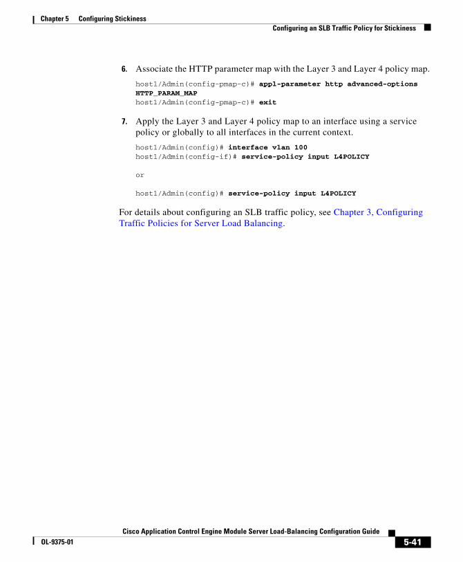
Chapter 5 Configuring StickinessConfiguring an SLB Traffic Policy for Stickiness
6. Associate the HTTP parameter map with the Layer 3 and Layer 4 policy map.
host1/Admin(config-pmap-c)# appl-parameter http advanced-options HTTP_PARAM_MAPhost1/Admin(config-pmap-c)# exit
7. Apply the Layer 3 and Layer 4 policy map to an interface using a service policy or globally to all interfaces in the current context.
host1/Admin(config)# interface vlan 100host1/Admin(config-if)# service-policy input L4POLICY
or
host1/Admin(config)# service-policy input L4POLICY
For details about configuring an SLB traffic policy, see Chapter 3, Configuring Traffic Policies for Server Load Balancing.
5-41Cisco Application Control Engine Module Server Load-Balancing Configuration Guide
OL-9375-01
Chapter 5 Configuring StickinessDisplaying Sticky Configurations and Statistics
Displaying Sticky Configurations and StatisticsThis section describes the show commands that you can use to display sticky configurations and statistic. It contains the following subsections:
• Displaying a Sticky Configuration
• Displaying Sticky Database Entries
• Displaying Sticky Statistics
Displaying a Sticky ConfigurationTo display the current sticky configuration, use the show running-config command in EXEC mode. The syntax of this command is:
show running-config sticky
The output of this command displays configured sticky groups and their attributes.
Displaying Sticky Database EntriesThe ACE stores sticky entries in a sticky database based on the following categories of information:
• Client IP address
• Sticky group ID
• HTTP-cookie value
• HTTP-header value
• Real-server name
• Static sticky database entries
• Sticky group type
5-42Cisco Application Control Engine Module Server Load-Balancing Configuration Guide
OL-9375-01

Chapter 5 Configuring StickinessDisplaying Sticky Configurations and Statistics
To display sticky database entry information, use the show sticky database command in EXEC mode. The syntax of this command is:
show sticky database [static] [client ip_address | group name1 | http-cookie value1 | http-header value2 | rserver name2 | type {http-cookie | http-header | ip-netmask}]
The keywords, arguments, and options are:
• static—Displays static sticky database entries for one of the static sticky entry types that follow.
• client ip_address—Displays sticky database entries for the source IP address of a client that you specify
• group name1—Displays sticky database entries for the sticky group name that you specify
• http-cookie value1—Displays sticky database entries for the HTTP-cookie value that you specify
• http-header value2—Displays sticky database entries for the HTTP-header value that you specify
• rserver name2—Displays sticky database entries for the real-server name that you specify
• type—Displays sticky database entries for one of the following sticky group types:
– http-cookie
– http-header
– ip-netmask
For example, enter:
host1/Admin# show sticky databasesticky group : src-iptype : IPtimeout : 1440 timeout-activeconns : FALSE sticky-entry rserver-instance time-to-expire flags ---------------------+-----------------------+----------+-------+ 3232236541 rs1:0 86399 -
5-43Cisco Application Control Engine Module Server Load-Balancing Configuration Guide
OL-9375-01

Chapter 5 Configuring StickinessDisplaying Sticky Configurations and Statistics
Table 5-5 describes the fields in the show sticky database command output.
Table 5-5 Field Descriptions for the show sticky database Command Output
Field Description
Sticky Group Name of the sticky group.
Type Kind of sticky group (for example, HTTP-HEADER).
Timeout Timeout (in minutes) for the entry in the sticky table.
Timeout- Activeconns
Indicates whether the timeout activeconns command is enabled or disabled. When enabled, this command times out sticky connections even when active connections exist. Possible values are: TRUE (enabled) or FLASE (disabled).
Sticky-Entry Hashed value of the sticky entry in the database.
Rserver-instance Name and, optionally, port of a real server associated with the sticky group (for example, rs1:81). If no port is configured for the real server in the serverfarm, the port displays as 0 (for example, rs1:0).
Time-To-Expire Time (in seconds) remaining for the sticky timeout. For sticky entries that have no expiration, the value is “never”. Static sticky entries always have a value of “never”.
Flags For future use.
Sticky Replicate Indicates whether the ACE replicates sticky entries to the peer ACE in a redundancy configuration.
Displaying Sticky StatisticsYou can display global sticky statistics for the current context by using the show stats sticky command in Exec mode. The syntax of this command is as follows:
show stats sticky
5-44Cisco Application Control Engine Module Server Load-Balancing Configuration Guide
OL-9375-01

Chapter 5 Configuring StickinessClearing Sticky Statistics
Table 5-6 describes the fields in the show stats sticky command output.
Table 5-6 Field Descriptions for the show stats sticky Command Output
Field Description
Total Sticky Entries Reused Prior to Expiry
Total number of entries in the sticky database that the ACE was able to use more than once before the entries timed out.
Total Active Sticky Entries
Total number of entries in the sticky database that currently have flows mapped to them.
Total Active Sticky Conns
Total number of sticky connections that are currently active.
Total Static Sticky Entries
Total number of configured static entries that are in the sticky database.
Clearing Sticky StatisticsTo clear all sticky statistics for the current context, use the clear stats sticky command in Exec mode. The syntax of this command is:
clear stats sticky
For example, to clear all sticky statistics for the Admin context, enter:
host1/Admin# clear stats sticky
Note If you have redundancy configured, then you need to explicitly clear sticky statistics on both the active and the standby ACEs. Clearing statistics on the active module alone will leave the standby module’s statistics at the old values.
5-45Cisco Application Control Engine Module Server Load-Balancing Configuration Guide
OL-9375-01
Chapter 5 Configuring StickinessClearing Dynamic Sticky Database Entries
Clearing Dynamic Sticky Database EntriesTo clear dynamic sticky database entries, use the clear sticky database command in Exec mode. The syntax of this command is:
clear sticky database {all | group group_name}
The keywords and arguments are:
• all—Clears all dynamic sticky database entries in the context
• group_name—Clears all dynamic sticky database entries for the specified sticky group
Note This command does not clear static sticky database entries. To clear static sticky database entries, use the no form of the static command.
For example, to clear all dynamic sticky database entries for the sticky group named GROUP1, enter:
host1/Admin# clear sticky database GROUP1
Example of a Sticky ConfigurationThis section provides a sample sticky configuration.
access-list ACL1 extended permit ip any any
resource-class RC1 limit-resource sticky minimum 10.00 maximum unlimited
context Admin member RC1
rserver SERVER1 address 192.168.12.15 probe PROBE1 inservice
rserver SERVER2 address 192.168.12.16 probe PROBE2 inservice
5-46Cisco Application Control Engine Module Server Load-Balancing Configuration Guide
OL-9375-01

Chapter 5 Configuring StickinessWhere to Go Next
serverfarm SFARM1 rserver SERVER1 inservice rserver SERVER2 inservice
sticky http-header Host GROUP4 serverfarm SFARM1 timeout 720 timeout activeconns replicate sticky header offset 3000 length 1000 static header Host rserver SERVER1 4000
class-map match-any L4CLASS 10 match virtual-address 192.168.12.15 netmask 255.255.255.0 tcp port eq 80
class-map type http loadbalance match-any L7CLASS 10 match http header Host header-value .*cisco.com
policy-map type loadbalance first-match L7POLICY class L7CLASS sticky-serverfarm GROUP4 insert-http Host header-value *.cisco.com
policy-map multi-match L4POLICY sequence interval 10 class L4CLASS policy L7POLICY
interface vlan 193 ip address 192.168.3.13 255.255.255.0 service-policy input L4POLICY no shutdown
Where to Go NextIf you want to configure firewall load balancing (FWLB), see Chapter 6, Configuring Firewall Load Balancing.
5-47Cisco Application Control Engine Module Server Load-Balancing Configuration Guide
OL-9375-01

Chapter 5 Configuring StickinessWhere to Go Next
5-48Cisco Application Control Engine Module Server Load-Balancing Configuration Guide
OL-9375-01

Cisco Application Control Engine Module Server LOL-9375-01
C H A P T E R 6
Configuring Firewall Load BalancingThis chapter describes how to configure firewall load balancing on your Cisco Application Control Engine (ACE) module. Firewall load balancing allows you to scale firewall protection by distributing traffic across multiple firewalls on a per-connection basis. All packets belonging to a particular connection must go through the same firewall. The firewall then allows or denies transmission of individual packets across its interfaces.
This chapter contains the following major sections:
• Understanding How Firewalls Work
• Configuring Standard Firewall Load Balancing
• Configuring Stealth Firewall Load Balancing
• Firewall Load-balancing Configurational Examples
Understanding How Firewalls WorkA firewall forms a physical barrier between two parts of a network, for example, the Internet and an intranet. When a firewall accepts a packet from one side (the Internet), it sends the packet through to the other side (the intranet). A firewall can modify a packet before passing it through or send it through unaltered. When a firewall rejects a packet, it typically discards the packet and logs the discarded packet as an event.
After a session is established and a flow of packets begins, a firewall can monitor each packet in the flow or allow the flow to continue unmonitored, depending on the policies that you configure on that firewall.
6-1oad-Balancing Configuration Guide

Chapter 6 Configuring Firewall Load BalancingUnderstanding How Firewalls Work
This section contains the following subsections:
• Firewall Types
• How the ACE Distributes Traffic to Firewalls
• Supported Firewall Configurations
Firewall TypesThe two basic types of firewalls are:
• Standard firewalls
• Stealth firewalls
Standard firewalls have a presence on the network. You assign IP addresses to the firewalls, which allows other devices on the network to see and address them as devices. Each firewall has an IP address on the VLANs configured on both sides of the firewall.
Stealth firewalls have no presence on the network. You do not assign IP addresses to the firewalls, which prevents other devices on the network from seeing or addressing them. Instead, you configure IP addresses on the ACE VLAN interfaces on both sides of the firewall. To the network, a stealth firewall is part of the wire.
Both firewall types:
• Examine traffic moving in both directions (between the protected and the unprotected sides of the network)
• Accept or reject packets based on user-defined policies
6-2Cisco Application Control Engine Module Server Load-Balancing Configuration Guide
OL-9375-01

Chapter 6 Configuring Firewall Load BalancingUnderstanding How Firewalls Work
How the ACE Distributes Traffic to FirewallsThe ACE load-balances traffic to devices configured in server farms. These devices can be firewalls, caches, servers, or any IP-addressable object. For more information about server farms, see the “Configuring a Server Farm” section in Chapter 2, Configuring Real Servers and Server Farms.When the ACE load-balances traffic to firewalls, it performs the same function that it performs when it load-balances Layer 3 traffic to real servers in a server farm.
The ACE uses load-balancing algorithms or predictors to determine how to balance the traffic among the devices configured in the server farms, independent of the device type. For FWLB, we recommend that you use only the hash address source and the hash address destination predictors. Using any other predictor with FWLB may fail and block traffic, especially for applications that have separate control and data channels, for example, FTP.
For more information about load-balancing predictor methods, see the “Configuring the Server Farm Predictor Method” section in Chapter 2, Configuring Real Servers and Server Farms.
Supported Firewall ConfigurationsThe ACE can load-balance traffic to both standard and stealth firewalls.
For standard firewalls, a single ACE or a pair of ACEs in two different Catalyst 6500 switches load-balances traffic among firewalls that contain unique IP addresses in a manner similar to how the ACE load-balances traffic among servers in a server farm (see Figure 6-1).
In Figure 6-1, traffic moves through the firewalls and the firewalls filter the traffic in both directions. For traffic originating on the Internet, ACE A load-balances the traffic to the firewalls in the SF_INSEC server farm. For traffic originating on the intranet, ACE B load-balances the traffic to the firewalls in server farm SF_SEC. You configure the firewalls so that the return traffic flows through the same firewall as the original traffic.
6-3Cisco Application Control Engine Module Server Load-Balancing Configuration Guide
OL-9375-01
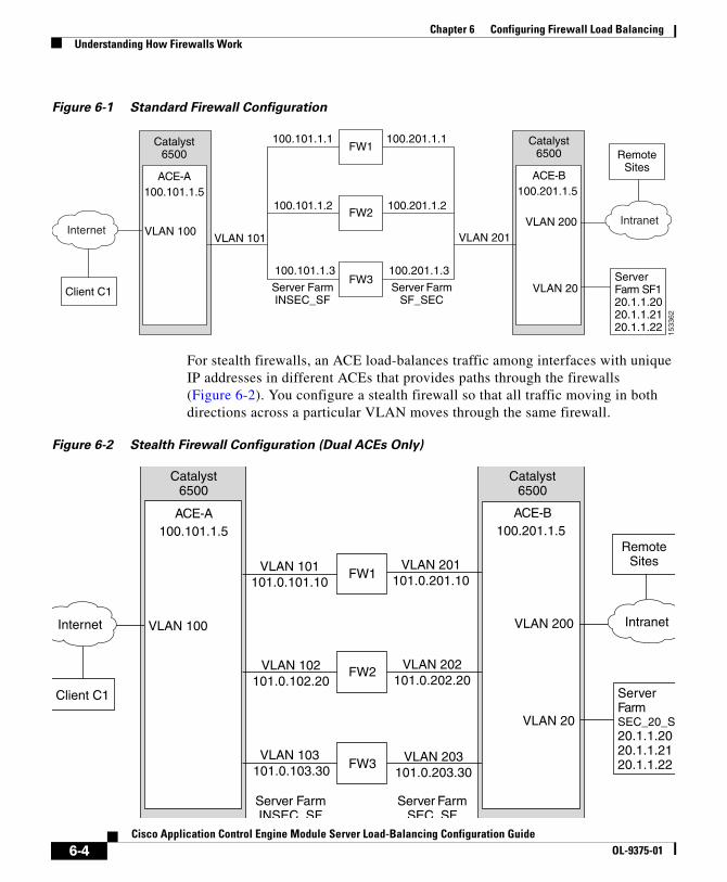
Chapter 6 Configuring Firewall Load BalancingUnderstanding How Firewalls Work
Figure 6-1 Standard Firewall Configuration
1533
62
FW1
Client C1
Catalyst6500
Catalyst6500
ServerFarm SF120.1.1.2020.1.1.2120.1.1.22
Server FarmINSEC_SF
Server FarmSF_SEC
100.101.1.1
100.101.1.2
100.101.1.3
100.201.1.1
100.201.1.2
100.201.1.3
FW2
FW3
VLAN 101 VLAN 201
RemoteSites
IntranetInternet
ACE-A100.101.1.5
VLAN 100
ACE-B100.201.1.5
VLAN 200
VLAN 20
For stealth firewalls, an ACE load-balances traffic among interfaces with unique IP addresses in different ACEs that provides paths through the firewalls (Figure 6-2). You configure a stealth firewall so that all traffic moving in both directions across a particular VLAN moves through the same firewall.
Figure 6-2 Stealth Firewall Configuration (Dual ACEs Only)
FW1
Client C1
Catalyst6500
Catalyst6500
ServerFarmSEC_20_S20.1.1.2020.1.1.2120.1.1.22
Server FarmINSEC SF
Server FarmSEC SF
VLAN 101101.0.101.10
VLAN 102101.0.102.20
VLAN 103 101.0.103.30
VLAN 201101.0.201.10
VLAN 202101.0.202.20
VLAN 203101.0.203.30
FW2
FW3
RemoteSites
IntranetInternet
ACE-A100.101.1.5
VLAN 100
ACE-B100.201.1.5
VLAN 200
VLAN 20
6-4Cisco Application Control Engine Module Server Load-Balancing Configuration Guide
OL-9375-01
Chapter 6 Configuring Firewall Load BalancingConfiguring Standard Firewall Load Balancing
In Figure 6-2, traffic flows through the firewalls and the firewalls filter the traffic in both directions. On the path to the intranet, ACE A balances traffic across VLANs 101, 102, and 103 through the firewalls to ACE B. On the path to the Internet, ACE B balances traffic across VLANs 201, 202, and 203 through the firewalls to ACE A.
Configuring Standard Firewall Load BalancingThis section describes how to configure firewall load balancing for standard firewalls. It contains the following subsections:
• Standard FWLB Configuration Overview
• Standard FWLB Configuration Quick Starts
Note For information about configuring the firewall devices in your network, refer to the documentation included with your firewall product.
Standard FWLB Configuration OverviewIn this standard FWLB configuration example (see Figure 6-1), you configure three firewalls (FW1, FW2, and FW3) between two ACEs (ACE A and ACE B). (You can also configure standard FWLB using a single ACE.) Traffic enters and exits the firewalls through shared VLANs on either side of the firewalls (VLAN 101on the insecure side and VLAN 201 on the secure side). You assign unique IP addresses to each firewall configured as a real server in a server farm on each shared VLAN.
Other VLANs provide connectivity to:
• Internet (VLAN 100)
• Internal network (VLAN 200)
• Internal server farm (VLAN 20)
6-5Cisco Application Control Engine Module Server Load-Balancing Configuration Guide
OL-9375-01

Chapter 6 Configuring Firewall Load BalancingConfiguring Standard Firewall Load Balancing
Standard FWLB Configuration Quick StartsThis section provides quick start tables that include step-by-step instructions for configuring standard FWLB on two ACE modules in separate Catalyst 6500 switches. Note that you can also configure standard FWLB on a single ACE. This section includes the following subsections:
• Standard FWLB Configuration Quick Start for ACE A
• Standard FWLB Configuration Quick Start for ACE B
Standard FWLB Configuration Quick Start for ACE A
Table 6-1 provides a quick overview of the steps required to configure standard FWLB on ACE A (see Figure 6-1). Each step includes the CLI command required to complete the task.
Table 6-1 Standard FWLB Configuration Quick Start for ACE A
Task and Command Example
1. If you are operating in multiple contexts, observe the CLI prompt to verify that you are operating in the desired context. If necessary, change to, or directly log in to, the correct context.
host1/Admin# changeto C1host1/C1#
The rest of the examples in this table use the Admin context for illustration purposes, unless otherwise specified. For details on creating contexts, refer to the Cisco Application Control Engine Module Administration Guide.
2. Enter configuration mode.
host1/Admin# configEnter configuration commands, one per line. End with CNTL/Zhost1/Admin(config)#
6-6Cisco Application Control Engine Module Server Load-Balancing Configuration Guide
OL-9375-01

Chapter 6 Configuring Firewall Load BalancingConfiguring Standard Firewall Load Balancing
3. Configure an access control list (ACL) to allow traffic. You can modify the ACL to suit your application needs. For more information about configuring ACLs, refer to the Cisco Application Control Engine Module Security Configuration Guide.
host1/Admin(config)# access-list ACL1 line 10 extended permit ip any anyhost1/Admin(config-acl)# exit
4. Configure three real servers to represent the insecure side of the firewalls on VLAN 101. For more information about configuring real servers, see Chapter 2, Configuring Real Servers and Server Farms.
host1/Admin(config)# rserver FW_INSEC_1host1/Admin(config-rserver-host)# ip address 100.101.1.1host1/Admin(config-rserver-host)# inservicehost1/Admin(config-rserver-host)# exit
host1/Admin(config)# rserver FW_INSEC_2host1/Admin(config-rserver-host)# ip address 100.101.1.2host1/Admin(config-rserver-host)# inservicehost1/Admin(config-rserver-host)# exit
host1/Admin(config)# rserver FW_INSEC_3host1/Admin(config-rserver-host)# ip address 100.101.1.3host1/Admin(config-rserver-host)# inservicehost1/Admin(config-rserver-host)# exit
Table 6-1 Standard FWLB Configuration Quick Start for ACE A (continued)
Task and Command Example
6-7Cisco Application Control Engine Module Server Load-Balancing Configuration Guide
OL-9375-01

Chapter 6 Configuring Firewall Load BalancingConfiguring Standard Firewall Load Balancing
5. Configure a server farm to handle connections originating from the insecure side of the firewalls (Internet). The ACE selects a firewall based on source IP address using the hash address source predictor. For more information about configuring server farms, see Chapter 2, Configuring Real Servers and Server Farms.
host1/Admin(config)# serverfarm SF_INSEChost1/Admin(config-sfarm-host)# transparenthost1/Admin(config-sfarm-host)# predictor hash address source 255.255.255.255host1/Admin(config-sfarm-host)# rserver FW_INSEC_1host1/Admin(config-sfarm-host-rs)# inservicehost1/Admin(config-sfarm-host-rs)# exithost1/Admin(config-sfarm-host)# rserver FW_INSEC_2host1/Admin(config-sfarm-host-rs)# inservicehost1/Admin(config-sfarm-host-rs)# exithost1/Admin(config-sfarm-host)# rserver FW_INSEC_3host1/Admin(config-sfarm-host-rs)# inservicehost1/Admin(config-sfarm-host-rs)# exithost1/Admin(config-sfarm-host)# exit
6. Configure a Layer 7 load-balancing policy map to balance requests to server farm SF-INSEC. Associate the default class map and the SF-INSEC server farm with the policy map. For more information about configuring traffic policies for SLB, see Chapter 3, Configuring Traffic Policies for Server Load Balancing.
host1/Admin(config)# policy-map type loadbalance first-match LB_FW_INSEChost1/Admin(config-pmap-lb)# class class-defaulthost1/Admin(config-pmap-lb-c)# serverfarm SF_INSEChost1/Admin(config-pmap-lb-c)# exithost1/Admin(config-pmap-lb)# exit
7. Configure a Layer 3 class map to classify traffic from the Internet that matches VIP address 200.1.1.1 on VLAN 100 on the insecure side of the firewalls. For more information about configuring traffic policies for SLB, see Chapter 3, Configuring Traffic Policies for Server Load Balancing.
host1/Admin(config)# class-map match-any FW_VIPhost1/Admin(config-cmap)# match virtual-address 200.1.1.1 255.255.0.0 anyhost1/Admin(config-cmap)# exit
Table 6-1 Standard FWLB Configuration Quick Start for ACE A (continued)
Task and Command Example
6-8Cisco Application Control Engine Module Server Load-Balancing Configuration Guide
OL-9375-01

Chapter 6 Configuring Firewall Load BalancingConfiguring Standard Firewall Load Balancing
8. Configure a Layer 3 policy map and associate the Layer 3 class map and the Layer 7 policy map with it to complete the traffic policy configuration. For more information about configuring traffic policies for SLB, see Chapter 3, Configuring Traffic Policies for Server Load Balancing.
host1/Admin(config)# policy-map multi-match POL_INSEChost1/Admin(config-pmap)# class FW_VIPhost1/Admin(config-pmap-c)# loadbalance vip inservicehost1/Admin(config-pmap-c)# loadbalance policy LB_FW_INSEChost1/Admin(config-pmap-c)# exithost1/Admin(config-pmap)# exit
9. Configure an interface that the ACE uses to receive traffic from the Internet and to send traffic originating from the intranet to the Internet. Apply the ACL (ACL1) and the Layer 3 policy (POL_INSEC) to the interface. For more information about configuring interfaces, refer to the Cisco Application Control Engine Module Routing and Bridging Configuration Guide.
host1/Admin(config)# interface vlan 100host1/Admin(config-if)# ip address 100.100.1.100 255.255.0.0host1/Admin(config-if)# access-group input ACL1host1/Admin(config-if)# service-policy input POL_INSEChost1/Admin(config-if)# no shutdownhost1/Admin(config-if)# exit
10. Configure an interface on the insecure side of the firewalls. The ACE uses this interface to load-balance traffic to the firewalls and to receive traffic originating from the intranet. For more information about configuring interfaces, refer to the Cisco Application Control Engine Module Routing and Bridging Configuration Guide.
host1/Admin(config)# interface vlan 101host1/Admin(config-if)# ip address 100.101.1.101 255.255.0.0host1/Admin(config-if)# access-group input ACL1host1/Admin(config-if)# mac-sticky enablehost1/Admin(config-if)# service-policy input POL_INSEChost1/Admin(config-if)# no shutdownhost1/Admin(config-if)# Ctrl-z
Table 6-1 Standard FWLB Configuration Quick Start for ACE A (continued)
Task and Command Example
6-9Cisco Application Control Engine Module Server Load-Balancing Configuration Guide
OL-9375-01
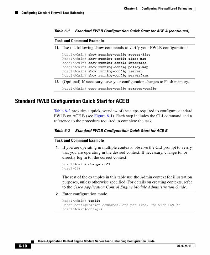
Chapter 6 Configuring Firewall Load BalancingConfiguring Standard Firewall Load Balancing
Standard FWLB Configuration Quick Start for ACE B
Table 6-2 provides a quick overview of the steps required to configure standard FWLB on ACE B (see Figure 6-1). Each step includes the CLI command and a reference to the procedure required to complete the task.
11. Use the following show commands to verify your FWLB configuration:
host1/Admin# show running-config access-listhost1/Admin# show running-config class-maphost1/Admin# show running-config interfacehost1/Admin# show running-config policy-maphost1/Admin# show running-config rserverhost1/Admin# show running-config serverfarm
12. (Optional) If necessary, save your configuration changes to Flash memory.
host1/Admin# copy running-config startup-config
Table 6-1 Standard FWLB Configuration Quick Start for ACE A (continued)
Task and Command Example
Table 6-2 Standard FWLB Configuration Quick Start for ACE B
Task and Command Example
1. If you are operating in multiple contexts, observe the CLI prompt to verify that you are operating in the desired context. If necessary, change to, or directly log in to, the correct context.
host1/Admin# changeto C1host1/C1#
The rest of the examples in this table use the Admin context for illustration purposes, unless otherwise specified. For details on creating contexts, refer to the Cisco Application Control Engine Module Administration Guide.
2. Enter configuration mode.
host1/Admin# configEnter configuration commands, one per line. End with CNTL/Zhost1/Admin(config)#
6-10Cisco Application Control Engine Module Server Load-Balancing Configuration Guide
OL-9375-01

Chapter 6 Configuring Firewall Load BalancingConfiguring Standard Firewall Load Balancing
3. Configure an ACL to allow traffic. You can modify the ACL to suit your application needs. For more information about configuring ACLs, refer to the Cisco Application Control Engine Module Security Configuration Guide.
host1/Admin(config)# access-list ACL1 line 10 extended permit ip any anyhost1/Admin(config-acl)# exit
4. Configure three real servers to represent the secure side of the firewalls on VLAN 201. For more information about configuring real servers, see Chapter 2, Configuring Real Servers and Server Farms.
host1/Admin(config)# rserver FW_SEC_1host1/Admin(config-rserver-host)# ip address 100.201.1.1host1/Admin(config-rserver-host)# inservicehost1/Admin(config-rserver-host)# exit
host1/Admin(config)# rserver FW_SEC_2host1/Admin(config-rserver-host)# ip address 100.201.1.2host1/Admin(config-rserver-host)# inservicehost1/Admin(config-rserver-host)# exit
host1/Admin(config)# rserver FW_SEC_3host1/Admin(config-rserver-host)# ip address 100.201.1.3host1/Admin(config-rserver-host)# inservicehost1/Admin(config-rserver-host)# exit
Table 6-2 Standard FWLB Configuration Quick Start for ACE B (continued)
Task and Command Example
6-11Cisco Application Control Engine Module Server Load-Balancing Configuration Guide
OL-9375-01

Chapter 6 Configuring Firewall Load BalancingConfiguring Standard Firewall Load Balancing
5. Configure a server farm to handle connections originating from the secure side of the firewall (intranet). In this case, the ACE selects a firewall based on the destination IP address using the hash address destination predictor. This predictor allows the ACE to select the same firewall for return flows and buddy connections. For example, you want both the FTP control and data channels to pass through the same firewall. For more information about configuring server farms, see Chapter 2, Configuring Real Servers and Server Farms.
host1/Admin(config)# serverfarm SF_SEChost1/Admin(config-sfarm-host)# transparenthost1/Admin(config-sfarm-host)# predictor hash address destination 255.255.255.255host1/Admin(config-sfarm-host)# rserver FW_SEC_1host1/Admin(config-sfarm-host-rs)# inservicehost1/Admin(config-sfarm-host-rs)# exithost1/Admin(config-sfarm-host)# rserver FW_SEC_2host1/Admin(config-sfarm-host-rs)# inservicehost1/Admin(config-sfarm-host-rs)# exithost1/Admin(config-sfarm-host)# rserver FW_SEC_3host1/Admin(config-sfarm-host-rs)# inservicehost1/Admin(config-sfarm-host)# exit
6. Configure two real servers to load-balance content on VLAN 20 on the secure side of the firewall. For more information about configuring server farms, see Chapter 2, Configuring Real Servers and Server Farms.
host1/Admin(config)# rserver REAL1host1/Admin(config-rserver-host)# ip address 20.1.1.1host1/Admin(config-rserver-host)# inservicehost1/Admin(config-rserver-host)# exit
host1/Admin(config)# rserver REAL2host1/Admin(config-rserver-host)# ip address 20.1.1.2host1/Admin(config-rserver-host)# inservicehost1/Admin(config-rserver-host)# exit
host1/Admin(config)# rserver REAL3host1/Admin(config-rserver-host)# ip address 20.1.1.3host1/Admin(config-rserver-host)# inservicehost1/Admin(config-rserver-host)# exit
Table 6-2 Standard FWLB Configuration Quick Start for ACE B (continued)
Task and Command Example
6-12Cisco Application Control Engine Module Server Load-Balancing Configuration Guide
OL-9375-01

Chapter 6 Configuring Firewall Load BalancingConfiguring Standard Firewall Load Balancing
7. Configure a standard server farm of HTTP servers. For more information about configuring server farms, see Chapter 2, Configuring Real Servers and Server Farms.
host1/Admin(config)# serverfarm SEC_20_SFhost1/Admin(config-sfarm-host)# rserver REAL1host1/Admin(config-sfarm-host-rs)# inservicehost1/Admin(config-sfarm-host-rs)# exithost1/Admin(config-sfarm-host)# rserver REAL2host1/Admin(config-sfarm-host-rs)# inservicehost1/Admin(config-sfarm-host-rs)# exithost1/Admin(config-sfarm-host)# rserver REAL3host1/Admin(config-sfarm-host-rs)# inservicehost1/Admin(config-sfarm-host-rs)# exithost1/Admin(config-sfarm-host)# exit
8. Configure a Layer 7 policy map that load-balances traffic to the HTTP server farm on VLAN 20 using the default class map. For more information about configuring traffic policies for SLB, see Chapter 3, Configuring Traffic Policies for Server Load Balancing.
host1/Admin(config)# policy-map type loadbalance first-match SEC_20_LBhost1/Admin(config-pmap-lb)# class class-defaulthost1/Admin(config-pmap-lb-c)# serverfarm SEC_20_SFhost1/Admin(config-pmap-lb-c)# exithost1/Admin(config-pmap-lb)# exit
9. Configure a Layer 3 class map to classify traffic destined to the virtual IP address 200.1.1.1 configured on VLAN 201. For more information about configuring traffic policies for SLB, see Chapter 3, Configuring Traffic Policies for Server Load Balancing.
host1/Admin(config)# class-map match-any SEC_20_VShost1/Admin(config-cmap)# match virtual-address 200.1.1.1 255.255.0.0 anyhost1/Admin(config-cmap)# exit
Table 6-2 Standard FWLB Configuration Quick Start for ACE B (continued)
Task and Command Example
6-13Cisco Application Control Engine Module Server Load-Balancing Configuration Guide
OL-9375-01
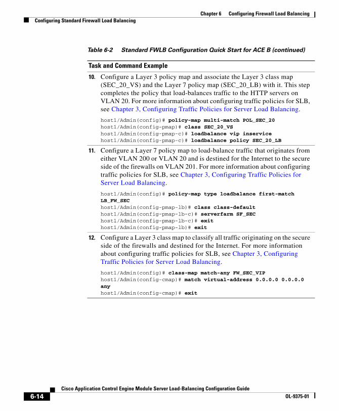
Chapter 6 Configuring Firewall Load BalancingConfiguring Standard Firewall Load Balancing
10. Configure a Layer 3 policy map and associate the Layer 3 class map (SEC_20_VS) and the Layer 7 policy map (SEC_20_LB) with it. This step completes the policy that load-balances traffic to the HTTP servers on VLAN 20. For more information about configuring traffic policies for SLB, see Chapter 3, Configuring Traffic Policies for Server Load Balancing.
host1/Admin(config)# policy-map multi-match POL_SEC_20host1/Admin(config-pmap)# class SEC_20_VShost1/Admin(config-pmap-c)# loadbalance vip inservicehost1/Admin(config-pmap-c)# loadbalance policy SEC_20_LB
11. Configure a Layer 7 policy map to load-balance traffic that originates from either VLAN 200 or VLAN 20 and is destined for the Internet to the secure side of the firewalls on VLAN 201. For more information about configuring traffic policies for SLB, see Chapter 3, Configuring Traffic Policies for Server Load Balancing.
host1/Admin(config)# policy-map type loadbalance first-match LB_FW_SEChost1/Admin(config-pmap-lb)# class class-defaulthost1/Admin(config-pmap-lb-c)# serverfarm SF_SEChost1/Admin(config-pmap-lb-c)# exithost1/Admin(config-pmap-lb)# exit
12. Configure a Layer 3 class map to classify all traffic originating on the secure side of the firewalls and destined for the Internet. For more information about configuring traffic policies for SLB, see Chapter 3, Configuring Traffic Policies for Server Load Balancing.
host1/Admin(config)# class-map match-any FW_SEC_VIPhost1/Admin(config-cmap)# match virtual-address 0.0.0.0 0.0.0.0 anyhost1/Admin(config-cmap)# exit
Table 6-2 Standard FWLB Configuration Quick Start for ACE B (continued)
Task and Command Example
6-14Cisco Application Control Engine Module Server Load-Balancing Configuration Guide
OL-9375-01

Chapter 6 Configuring Firewall Load BalancingConfiguring Standard Firewall Load Balancing
13. Configure a Layer 3 policy map and associate the Layer 7 policy map (LB_FW_SEC) and the Layer 3 class map (FW_SEC_VIP) with it. Enable the VIP for load balancing. This step completes the policy that load-balances any request originating on the secure side of the firewalls and destined for the Internet. For more information about configuring traffic policies for SLB, see Chapter 3, Configuring Traffic Policies for Server Load Balancing.
host1/Admin(config)# policy-map multi-match POL_SEChost1/Admin(config-pmap)# class FW_SEC_VIPhost1/Admin(config-pmap-c)# loadbalance vip inservicehost1/Admin(config-pmap-c)# loadbalance LB_FW_SEChost1/Admin(config-pmap-c)# exithost1/Admin(config-pmap)# exit
14. Configure an interface on the secure side of the firewalls for traffic originating from the Internet and passing through the firewalls. The ACE uses this interface to catch traffic from the firewalls and load-balance it to the HTTP server farm and route traffic to the remote host. For more information about configuring interfaces, refer to the Cisco Application Control Engine Module Routing and Bridging Configuration Guide.
host1/Admin(config)# interface vlan 201host1/Admin(config-if)# ip address 100.201.1.201 255.255.0.0host1/Admin(config-if)# access-group input ACL1host1/Admin(config-if)# mac-sticky enablehost1/Admin(config-if)# service-policy input POL_SEC_20host1/Admin(config-if)# no shutdownhost1/Admin(config-if)# exit
15. Configure an interface on the secure side of the firewalls for traffic that originates from the HTTP server farm on VLAN 20. For more information about configuring interfaces, refer to the Cisco Application Control Engine Module Routing and Bridging Configuration Guide.
host1/Admin(config)# interface vlan 20host1/Admin(config-if)# ip address 20.1.1.20 255.255.255.0host1/Admin(config-if)# access-group input ACL1host1/Admin(config-if)# service-policy input POL_SEChost1/Admin(config-if)# no shutdownhost1/Admin(config-if)# exit
Table 6-2 Standard FWLB Configuration Quick Start for ACE B (continued)
Task and Command Example
6-15Cisco Application Control Engine Module Server Load-Balancing Configuration Guide
OL-9375-01
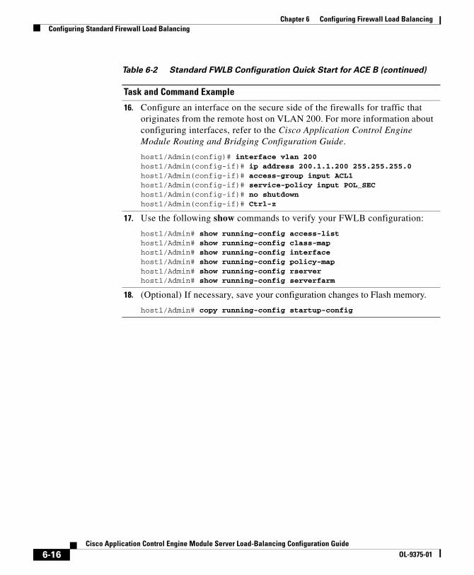
Chapter 6 Configuring Firewall Load BalancingConfiguring Standard Firewall Load Balancing
16. Configure an interface on the secure side of the firewalls for traffic that originates from the remote host on VLAN 200. For more information about configuring interfaces, refer to the Cisco Application Control Engine Module Routing and Bridging Configuration Guide.
host1/Admin(config)# interface vlan 200host1/Admin(config-if)# ip address 200.1.1.200 255.255.255.0host1/Admin(config-if)# access-group input ACL1host1/Admin(config-if)# service-policy input POL_SEChost1/Admin(config-if)# no shutdownhost1/Admin(config-if)# Ctrl-z
17. Use the following show commands to verify your FWLB configuration:
host1/Admin# show running-config access-listhost1/Admin# show running-config class-maphost1/Admin# show running-config interfacehost1/Admin# show running-config policy-maphost1/Admin# show running-config rserverhost1/Admin# show running-config serverfarm
18. (Optional) If necessary, save your configuration changes to Flash memory.
host1/Admin# copy running-config startup-config
Table 6-2 Standard FWLB Configuration Quick Start for ACE B (continued)
Task and Command Example
6-16Cisco Application Control Engine Module Server Load-Balancing Configuration Guide
OL-9375-01

Chapter 6 Configuring Firewall Load BalancingConfiguring Stealth Firewall Load Balancing
Configuring Stealth Firewall Load BalancingThis section describes how to configure stealth FWLB. It contains the following subsections:
• Stealth Firewall Load-Balancing Configuration Overview
• Stealth Firewall Load-Balancing Configuration Quick Starts
Note For information about configuring the firewall devices in your network, refer to the documentation included with your firewall product.
Stealth Firewall Load-Balancing Configuration Overview
Note In a stealth FWLB configuration, you must configure two ACEs, each in a separate Catalyst 6500 switch.
In this stealth FWLB configuration example (see Figure 6-2), ACE A and ACE B load-balance traffic through three firewalls. Each firewall configured as a real server in a server farm connects to two different VLANs, one on the insecure side and one on the secure side of the firewall.
On the path from the Internet to the intranet, traffic enters the insecure side of the firewalls through separate VLANs (VLAN 101,VLAN 102, and VLAN 103) and exits the secure side of the firewalls through separate VLANs (VLAN 201, VLAN 202, and VLAN 203). On the path from the intranet to the Internet, the flow is reversed. Other VLANs provide connectivity to the:
• Internet (VLAN 100)
• Remote host (VLAN 200)
• Intranet server farm (VLAN 20)
6-17Cisco Application Control Engine Module Server Load-Balancing Configuration Guide
OL-9375-01

Chapter 6 Configuring Firewall Load BalancingConfiguring Stealth Firewall Load Balancing
Stealth Firewall Load-Balancing Configuration Quick StartsThis section provides quick start tables that include step-by-step instructions about how to configure stealth FWLB on two separate ACE modules. This section includes the following subsections:
• Stealth FWLB Configuration Quick Start for ACE A
• Stealth FWLB Configuration Quick Start for ACE B
Stealth FWLB Configuration Quick Start for ACE A
Table 6-3 provides a quick overview of the steps required to configure stealth FWLB on ACE A (insecure side). Each step includes the CLI command required to complete the task.
Table 6-3 Stealth FWLB Configuration Quick Start for ACE A
Task and Command Example
1. If you are operating in multiple contexts, observe the CLI prompt to verify that you are operating in the desired context. If necessary, change to, or directly log in to, the correct context.
host1/Admin# changeto C1host1/C1#
The rest of the examples in this table use the Admin context for illustration purposes, unless otherwise specified. For details on creating contexts, refer to the Cisco Application Control Engine Module Administration Guide.
2. Enter configuration mode.
host1/Admin# configEnter configuration commands, one per line. End with CNTL/Zhost1/Admin(config)#
3. Configure an ACL to allow traffic to the ACE. You can modify the ACL to suit your application needs. For more information about configuring ACLs, refer to the Cisco Application Control Engine Module Security Configuration Guide
host1/Admin(config)# access-list ACL1 line 10 extended permit ip any anyhost1/Admin(config-acl)# exit
6-18Cisco Application Control Engine Module Server Load-Balancing Configuration Guide
OL-9375-01
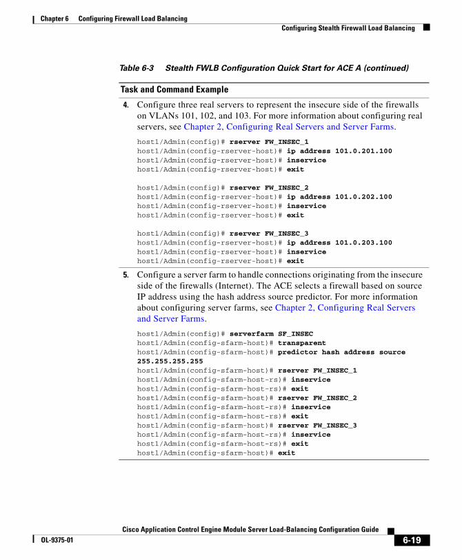
Chapter 6 Configuring Firewall Load BalancingConfiguring Stealth Firewall Load Balancing
4. Configure three real servers to represent the insecure side of the firewalls on VLANs 101, 102, and 103. For more information about configuring real servers, see Chapter 2, Configuring Real Servers and Server Farms.
host1/Admin(config)# rserver FW_INSEC_1host1/Admin(config-rserver-host)# ip address 101.0.201.100host1/Admin(config-rserver-host)# inservicehost1/Admin(config-rserver-host)# exit
host1/Admin(config)# rserver FW_INSEC_2host1/Admin(config-rserver-host)# ip address 101.0.202.100host1/Admin(config-rserver-host)# inservicehost1/Admin(config-rserver-host)# exit
host1/Admin(config)# rserver FW_INSEC_3host1/Admin(config-rserver-host)# ip address 101.0.203.100host1/Admin(config-rserver-host)# inservicehost1/Admin(config-rserver-host)# exit
5. Configure a server farm to handle connections originating from the insecure side of the firewalls (Internet). The ACE selects a firewall based on source IP address using the hash address source predictor. For more information about configuring server farms, see Chapter 2, Configuring Real Servers and Server Farms.
host1/Admin(config)# serverfarm SF_INSEChost1/Admin(config-sfarm-host)# transparenthost1/Admin(config-sfarm-host)# predictor hash address source 255.255.255.255host1/Admin(config-sfarm-host)# rserver FW_INSEC_1host1/Admin(config-sfarm-host-rs)# inservicehost1/Admin(config-sfarm-host-rs)# exithost1/Admin(config-sfarm-host)# rserver FW_INSEC_2host1/Admin(config-sfarm-host-rs)# inservicehost1/Admin(config-sfarm-host-rs)# exithost1/Admin(config-sfarm-host)# rserver FW_INSEC_3host1/Admin(config-sfarm-host-rs)# inservicehost1/Admin(config-sfarm-host-rs)# exithost1/Admin(config-sfarm-host)# exit
Table 6-3 Stealth FWLB Configuration Quick Start for ACE A (continued)
Task and Command Example
6-19Cisco Application Control Engine Module Server Load-Balancing Configuration Guide
OL-9375-01
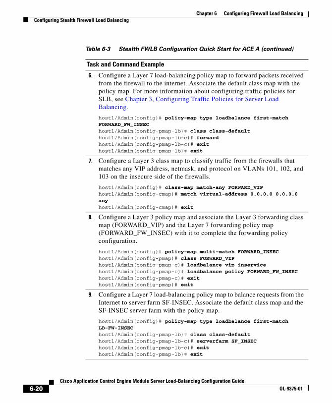
Chapter 6 Configuring Firewall Load BalancingConfiguring Stealth Firewall Load Balancing
6. Configure a Layer 7 load-balancing policy map to forward packets received from the firewall to the internet. Associate the default class map with the policy map. For more information about configuring traffic policies for SLB, see Chapter 3, Configuring Traffic Policies for Server Load Balancing.
host1/Admin(config)# policy-map type loadbalance first-match FORWARD_FW_INSEChost1/Admin(config-pmap-lb)# class class-defaulthost1/Admin(config-pmap-lb-c)# forwardhost1/Admin(config-pmap-lb-c)# exithost1/Admin(config-pmap-lb)# exit
7. Configure a Layer 3 class map to classify traffic from the firewalls that matches any VIP address, netmask, and protocol on VLANs 101, 102, and 103 on the insecure side of the firewalls.
host1/Admin(config)# class-map match-any FORWARD_VIPhost1/Admin(config-cmap)# match virtual-address 0.0.0.0 0.0.0.0 anyhost1/Admin(config-cmap)# exit
8. Configure a Layer 3 policy map and associate the Layer 3 forwarding class map (FORWARD_VIP) and the Layer 7 forwarding policy map (FORWARD_FW_INSEC) with it to complete the forwarding policy configuration.
host1/Admin(config)# policy-map multi-match FORWARD_INSEChost1/Admin(config-pmap)# class FORWARD_VIPhost1/Admin(config-pmap-c)# loadbalance vip inservicehost1/Admin(config-pmap-c)# loadbalance policy FORWARD_FW_INSEChost1/Admin(config-pmap-c)# exithost1/Admin(config-pmap)# exit
9. Configure a Layer 7 load-balancing policy map to balance requests from the Internet to server farm SF-INSEC. Associate the default class map and the SF-INSEC server farm with the policy map.
host1/Admin(config)# policy-map type loadbalance first-match LB-FW-INSEChost1/Admin(config-pmap-lb)# class class-defaulthost1/Admin(config-pmap-lb-c)# serverfarm SF_INSEChost1/Admin(config-pmap-lb-c)# exithost1/Admin(config-pmap-lb)# exit
Table 6-3 Stealth FWLB Configuration Quick Start for ACE A (continued)
Task and Command Example
6-20Cisco Application Control Engine Module Server Load-Balancing Configuration Guide
OL-9375-01

Chapter 6 Configuring Firewall Load BalancingConfiguring Stealth Firewall Load Balancing
10. Configure a Layer 3 class map to classify traffic from the Internet that matches VIP address 200.1.1.1, netmask 255.255.0.0, and any protocol on VLAN 100 on the insecure side of the firewalls.
host1/Admin(config)# class-map match-any FW_VIPhost1/Admin(config-cmap)# match virtual-address 200.1.1.1 255.255.0.0 anyhost1/Admin(config-cmap)# exit
11. Configure a Layer 3 policy map and associate the Layer 3 class map (FW-VIP) and the Layer 7 policy map (LB_FW_INSEC) with it to complete the load-balancing policy configuration.
host1/Admin(config)# policy-map multi-match POL_INSEChost1/Admin(config-pmap)# class FW_VIPhost1/Admin(config-pmap-c)# loadbalance vip inservicehost1/Admin(config-pmap-c)# loadbalance policy LB_FW_INSEChost1/Admin(config-pmap-c)# exithost1/Admin(config-pmap)# exit
12. Configure an interface that the ACE uses to receive traffic from the Internet and load-balance the traffic to the insecure side of the firewall. Apply the ACL (ACL1) and the Layer 3 policy (POL_INSEC) to the interface. For more information about configuring interfaces, refer to the Cisco Application Control Engine Module Routing and Bridging Configuration Guide.
host1/Admin(config)# interface vlan 100host1/Admin(config-if)# ip address 100.100.1.100 255.255.0.0host1/Admin(config-if)# access-group input ACL1host1/Admin(config-if)# service-policy input POL_INSEChost1/Admin(config-if)# no shutdownhost1/Admin(config-if)# exit
Table 6-3 Stealth FWLB Configuration Quick Start for ACE A (continued)
Task and Command Example
6-21Cisco Application Control Engine Module Server Load-Balancing Configuration Guide
OL-9375-01

Chapter 6 Configuring Firewall Load BalancingConfiguring Stealth Firewall Load Balancing
13. Configure an interface on the insecure side of the firewalls that ACE A uses to load-balance traffic to FW1 and to receive traffic originating from the intranet. For more information about configuring interfaces, refer to the Cisco Application Control Engine Module Routing and Bridging Configuration Guide.
host1/Admin(config)# interface vlan 101host1/Admin(config-if)# ip address 101.0.101.10 255.255.0.0host1/Admin(config-if)# access-group input ACL1host1/Admin(config-if)# mac-sticky enablehost1/Admin(config-if)# service-policy input FORWARD_INSEChost1/Admin(config-if)# no shutdownhost1/Admin(config-if)# exit
14. Configure an interface on the insecure side of the firewalls that ACE A uses to load-balance traffic to FW2 and to receive traffic originating from the intranet. For more information about configuring interfaces, refer to the Cisco Application Control Engine Module Routing and Bridging Configuration Guide.
host1/Admin(config)# interface vlan 102host1/Admin(config-if)# ip address 101.0.102.20 255.255.0.0host1/Admin(config-if)# access-group input ACL1host1/Admin(config-if)# mac-sticky enablehost1/Admin(config-if)# service-policy input FORWARD_INSEChost1/Admin(config-if)# no shutdownhost1/Admin(config-if)# exit
15. Configure an interface on the insecure side of the firewalls that ACE A uses load-balance traffic to the FW3 and to receive traffic originating from the intranet. For more information about configuring interfaces, refer to the Cisco Application Control Engine Module Routing and Bridging Configuration Guide.
host1/Admin(config)# interface vlan 103host1/Admin(config-if)# ip address 101.0.103.30 255.255.0.0host1/Admin(config-if)# access-group input ACL1host1/Admin(config-if)# mac-sticky enablehost1/Admin(config-if)# service-policy input FORWARD_INSEChost1/Admin(config-if)# no shutdownhost1/Admin(config-if)# Ctrl-z
Table 6-3 Stealth FWLB Configuration Quick Start for ACE A (continued)
Task and Command Example
6-22Cisco Application Control Engine Module Server Load-Balancing Configuration Guide
OL-9375-01
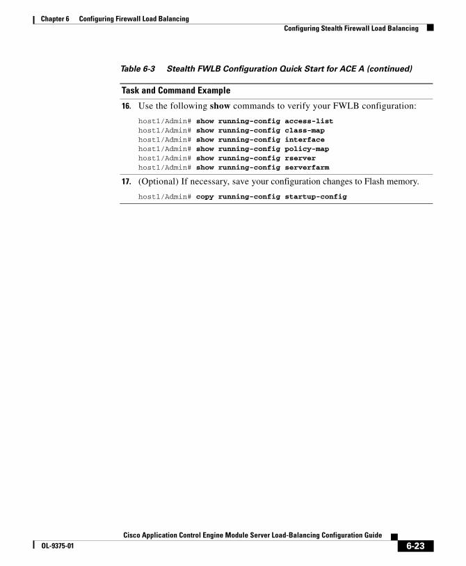
Chapter 6 Configuring Firewall Load BalancingConfiguring Stealth Firewall Load Balancing
16. Use the following show commands to verify your FWLB configuration:
host1/Admin# show running-config access-listhost1/Admin# show running-config class-maphost1/Admin# show running-config interfacehost1/Admin# show running-config policy-maphost1/Admin# show running-config rserverhost1/Admin# show running-config serverfarm
17. (Optional) If necessary, save your configuration changes to Flash memory.
host1/Admin# copy running-config startup-config
Table 6-3 Stealth FWLB Configuration Quick Start for ACE A (continued)
Task and Command Example
6-23Cisco Application Control Engine Module Server Load-Balancing Configuration Guide
OL-9375-01
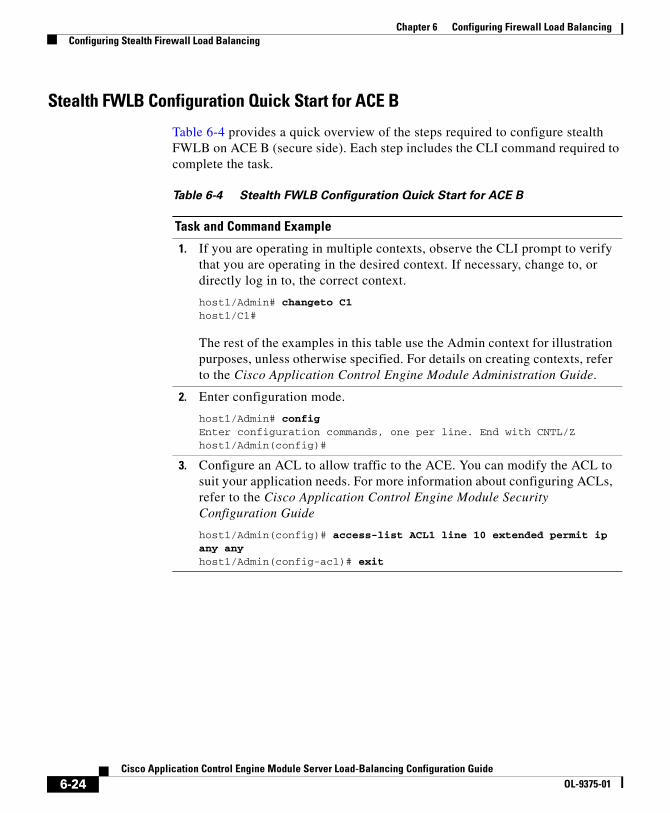
Chapter 6 Configuring Firewall Load BalancingConfiguring Stealth Firewall Load Balancing
Stealth FWLB Configuration Quick Start for ACE B
Table 6-4 provides a quick overview of the steps required to configure stealth FWLB on ACE B (secure side). Each step includes the CLI command required to complete the task.
Table 6-4 Stealth FWLB Configuration Quick Start for ACE B
Task and Command Example
1. If you are operating in multiple contexts, observe the CLI prompt to verify that you are operating in the desired context. If necessary, change to, or directly log in to, the correct context.
host1/Admin# changeto C1host1/C1#
The rest of the examples in this table use the Admin context for illustration purposes, unless otherwise specified. For details on creating contexts, refer to the Cisco Application Control Engine Module Administration Guide.
2. Enter configuration mode.
host1/Admin# configEnter configuration commands, one per line. End with CNTL/Zhost1/Admin(config)#
3. Configure an ACL to allow traffic to the ACE. You can modify the ACL to suit your application needs. For more information about configuring ACLs, refer to the Cisco Application Control Engine Module Security Configuration Guide
host1/Admin(config)# access-list ACL1 line 10 extended permit ip any anyhost1/Admin(config-acl)# exit
6-24Cisco Application Control Engine Module Server Load-Balancing Configuration Guide
OL-9375-01
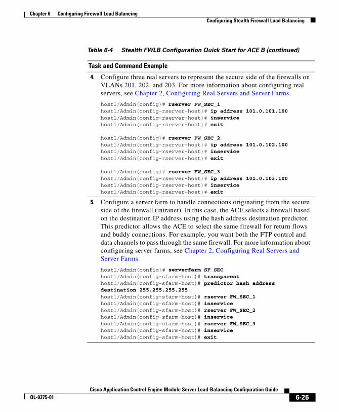
Chapter 6 Configuring Firewall Load BalancingConfiguring Stealth Firewall Load Balancing
4. Configure three real servers to represent the secure side of the firewalls on VLANs 201, 202, and 203. For more information about configuring real servers, see Chapter 2, Configuring Real Servers and Server Farms.
host1/Admin(config)# rserver FW_SEC_1host1/Admin(config-rserver-host)# ip address 101.0.101.100host1/Admin(config-rserver-host)# inservicehost1/Admin(config-rserver-host)# exit
host1/Admin(config)# rserver FW_SEC_2host1/Admin(config-rserver-host)# ip address 101.0.102.100host1/Admin(config-rserver-host)# inservicehost1/Admin(config-rserver-host)# exit
host1/Admin(config)# rserver FW_SEC_3host1/Admin(config-rserver-host)# ip address 101.0.103.100host1/Admin(config-rserver-host)# inservicehost1/Admin(config-rserver-host)# exit
5. Configure a server farm to handle connections originating from the secure side of the firewall (intranet). In this case, the ACE selects a firewall based on the destination IP address using the hash address destination predictor. This predictor allows the ACE to select the same firewall for return flows and buddy connections. For example, you want both the FTP control and data channels to pass through the same firewall. For more information about configuring server farms, see Chapter 2, Configuring Real Servers and Server Farms.
host1/Admin(config)# serverfarm SF_SEChost1/Admin(config-sfarm-host)# transparenthost1/Admin(config-sfarm-host)# predictor hash address destination 255.255.255.255host1/Admin(config-sfarm-host)# rserver FW_SEC_1host1/Admin(config-sfarm-host)# inservicehost1/Admin(config-sfarm-host)# rserver FW_SEC_2host1/Admin(config-sfarm-host)# inservicehost1/Admin(config-sfarm-host)# rserver FW_SEC_3host1/Admin(config-sfarm-host)# inservicehost1/Admin(config-sfarm-host)# exit
Table 6-4 Stealth FWLB Configuration Quick Start for ACE B (continued)
Task and Command Example
6-25Cisco Application Control Engine Module Server Load-Balancing Configuration Guide
OL-9375-01

Chapter 6 Configuring Firewall Load BalancingConfiguring Stealth Firewall Load Balancing
6. Configure three real servers to load-balance content on VLAN 20 on the secure side of the firewall. For more information about configuring real servers, see Chapter 2, Configuring Real Servers and Server Farms.
host1/Admin(config)# rserver REAL1host1/Admin(config-rserver-host)# ip address 20.1.1.1host1/Admin(config-rserver-host)# inservicehost1/Admin(config-rserver-host)# exit
host1/Admin(config)# rserver REAL2host1/Admin(config-rserver-host)# ip address 20.1.1.2host1/Admin(config-rserver-host)# inservicehost1/Admin(config-rserver-host)# exit
host1/Admin(config)# rserver REAL3host1/Admin(config-rserver-host)# ip address 20.1.1.3host1/Admin(config-rserver-host)# inservicehost1/Admin(config-rserver-host)# exit
7. Configure a standard server farm of HTTP servers to load-balance requests to the HTTP servers on VLAN 20. For more information about configuring server farms, see Chapter 2, Configuring Real Servers and Server Farms.
host1/Admin(config)# serverfarm SEC_20_SFhost1/Admin(config-sfarm-host)# rserver REAL1host1/Admin(config-sfarm-host-rs)# inservicehost1/Admin(config-sfarm-host-rs)# exithost1/Admin(config-sfarm-host)# rserver REAL2host1/Admin(config-sfarm-host-rs)# inservicehost1/Admin(config-sfarm-host-rs)# exithost1/Admin(config-sfarm-host)# rserver REAL3host1/Admin(config-sfarm-host-rs)# inservicehost1/Admin(config-sfarm-host-rs)# exithost1/Admin(config-sfarm-host)# exit
Table 6-4 Stealth FWLB Configuration Quick Start for ACE B (continued)
Task and Command Example
6-26Cisco Application Control Engine Module Server Load-Balancing Configuration Guide
OL-9375-01

Chapter 6 Configuring Firewall Load BalancingConfiguring Stealth Firewall Load Balancing
8. Configure a Layer 7 policy map that load-balances traffic to the HTTP server farm on VLAN 20 using the default class map. For more information about configuring traffic policies for SLB, see Chapter 3, Configuring Traffic Policies for Server Load Balancing.
host1/Admin(config)# policy-map type loadbalance first-match SEC_20_LBhost1/Admin(config-pmap-lb)# class class-defaulthost1/Admin(config-pmap-lb-c)# serverfarm SEC_20_SFhost1/Admin(config-pmap-lb-c)# exithost1/Admin(config-pmap-lb)# exit
9. Configure a Layer 3 class map to classify traffic destined to the virtual IP address 200.1.1.1 on VLANs 201, 202, and 203. For more information about configuring traffic policies for SLB, see Chapter 3, Configuring Traffic Policies for Server Load Balancing.
host1/Admin(config)# class-map match-any SEC_20_VShost1/Admin(config-cmap)# match virtual-address 200.1.1.1 255.255.0.0 anyhost1/Admin(config-cmap)# exit
10. Configure a Layer 3 policy map and associate the Layer 3 class map (SEC_20_VS) and the Layer 7 policy map (SEC_20_LB) with it. This step completes the policy that load-balances traffic to the HTTP servers on VLAN 20. For more information about configuring traffic policies for SLB, see Chapter 3, Configuring Traffic Policies for Server Load Balancing.
host1/Admin(config)# policy-map multi-match POL_SEC_20host1/Admin(config-pmap)# class SEC_20_VShost1/Admin(config-pmap-c)# loadbalance vip inservicehost1/Admin(config-pmap-c)# loadbalance policy SEC_20_LBhost1/Admin(config-pmap-c)# exithost1/Admin(config-pmap)# exit
Table 6-4 Stealth FWLB Configuration Quick Start for ACE B (continued)
Task and Command Example
6-27Cisco Application Control Engine Module Server Load-Balancing Configuration Guide
OL-9375-01
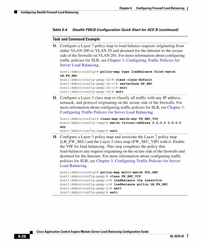
Chapter 6 Configuring Firewall Load BalancingConfiguring Stealth Firewall Load Balancing
11. Configure a Layer 7 policy map to load-balance requests originating from either VLAN 200 or VLAN 20 and destined for the Internet to the secure side of the firewalls on VLAN 201. For more information about configuring traffic policies for SLB, see Chapter 3, Configuring Traffic Policies for Server Load Balancing.
host1/Admin(config)# policy-map type loadbalance first-match LB_FW_SEChost1/Admin(config-pmap-lb)# class class-defaulthost1/Admin(config-pmap-lb-c)# serverfarm SF_SEChost1/Admin(config-pmap-lb-c)# exithost1/Admin(config-pmap-lb)# exit
12. Configure a Layer 3 class map to classify all traffic with any IP address, netmask, and protocol originating on the secure side of the firewalls. For more information about configuring traffic policies for SLB, see Chapter 3, Configuring Traffic Policies for Server Load Balancing.
host1/Admin(config)# class-map match-any FW_SEC_VIPhost1/Admin(config-cmap)# match virtual-address 0.0.0.0 0.0.0.0 anyhost1/Admin(config-cmap)# exit
13. Configure a Layer 3 policy map and associate the Layer 7 policy map (LB_FW_SEC) and the Layer 3 class map (FW_SEC_VIP) with it. Enable the VIP for load balancing. This step completes the policy that load-balances any request originating on the secure side of the firewalls and destined for the Internet. For more information about configuring traffic policies for SLB, see Chapter 3, Configuring Traffic Policies for Server Load Balancing.
host1/Admin(config)# policy-map multi-match POL_SEChost1/Admin(config-pmap)# class FW_SEC_VIPhost1/Admin(config-pmap-c)# loadbalance vip inservicehost1/Admin(config-pmap-c)# loadbalance policy LB_FW_SEChost1/Admin(config-pmap-c)# exithost1/Admin(config-pmap)# exit
Table 6-4 Stealth FWLB Configuration Quick Start for ACE B (continued)
Task and Command Example
6-28Cisco Application Control Engine Module Server Load-Balancing Configuration Guide
OL-9375-01

Chapter 6 Configuring Firewall Load BalancingConfiguring Stealth Firewall Load Balancing
14. Configure an interface on the secure side of the firewalls that the ACE uses to send traffic to FW1 from the intranet and to receive traffic originating from the Internet and passing through the firewall. For more information about configuring interfaces, refer to the Cisco Application Control Engine Module Routing and Bridging Configuration Guide.
host1/Admin(config)# interface vlan 201host1/Admin(config-if)# ip address 101.0.201.10 255.255.0.0host1/Admin(config-if)# access-group input ACL1host1/Admin(config-if)# mac-sticky enablehost1/Admin(config-if)# service-policy input POL_SEC_20host1/Admin(config-if)# no shutdownhost1/Admin(config-if)# exit
15. Configure an interface on the secure side of the firewalls that the ACE uses to send traffic to FW2 from the intranet and to receive traffic originating from the Internet and passing through the firewall. For more information about configuring interfaces, refer to the Cisco Application Control Engine Module Routing and Bridging Configuration Guide.
host1/Admin(config)# interface vlan 202host1/Admin(config-if)# ip address 101.0.202.20 255.255.0.0host1/Admin(config-if)# access-group input ACL1host1/Admin(config-if)# mac-sticky enablehost1/Admin(config-if)# service-policy input POL_SEC_20host1/Admin(config-if)# no shutdownhost1/Admin(config-if)# exit
16. Configure an interface on the insecure side of the firewall that the ACE uses to send traffic to FW3 from the intranet and to receive traffic originating from the Internet passing through he firewall. For more information about configuring interfaces, refer to the Cisco Application Control Engine Module Routing and Bridging Configuration Guide.
host1/Admin(config)# interface vlan 203host1/Admin(config-if)# ip address 101.0.203.30 255.255.0.0host1/Admin(config-if)# access-group input ACL1host1/Admin(config-if)# mac-sticky enablehost1/Admin(config-if)# service-policy input POL_SEC_20host1/Admin(config-if)# no shutdownhost1/Admin(config-if)# exit
Table 6-4 Stealth FWLB Configuration Quick Start for ACE B (continued)
Task and Command Example
6-29Cisco Application Control Engine Module Server Load-Balancing Configuration Guide
OL-9375-01
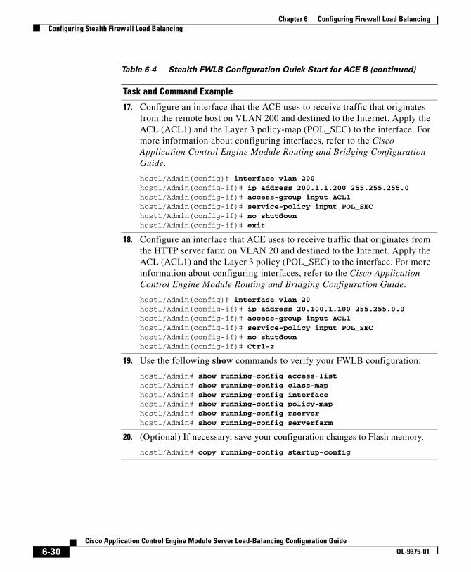
Chapter 6 Configuring Firewall Load BalancingConfiguring Stealth Firewall Load Balancing
17. Configure an interface that the ACE uses to receive traffic that originates from the remote host on VLAN 200 and destined to the Internet. Apply the ACL (ACL1) and the Layer 3 policy-map (POL_SEC) to the interface. For more information about configuring interfaces, refer to the Cisco Application Control Engine Module Routing and Bridging Configuration Guide.
host1/Admin(config)# interface vlan 200host1/Admin(config-if)# ip address 200.1.1.200 255.255.255.0host1/Admin(config-if)# access-group input ACL1host1/Admin(config-if)# service-policy input POL_SEChost1/Admin(config-if)# no shutdownhost1/Admin(config-if)# exit
18. Configure an interface that ACE uses to receive traffic that originates from the HTTP server farm on VLAN 20 and destined to the Internet. Apply the ACL (ACL1) and the Layer 3 policy (POL_SEC) to the interface. For more information about configuring interfaces, refer to the Cisco Application Control Engine Module Routing and Bridging Configuration Guide.
host1/Admin(config)# interface vlan 20host1/Admin(config-if)# ip address 20.100.1.100 255.255.0.0host1/Admin(config-if)# access-group input ACL1host1/Admin(config-if)# service-policy input POL_SEChost1/Admin(config-if)# no shutdownhost1/Admin(config-if)# Ctrl-z
19. Use the following show commands to verify your FWLB configuration:
host1/Admin# show running-config access-listhost1/Admin# show running-config class-maphost1/Admin# show running-config interfacehost1/Admin# show running-config policy-maphost1/Admin# show running-config rserverhost1/Admin# show running-config serverfarm
20. (Optional) If necessary, save your configuration changes to Flash memory.
host1/Admin# copy running-config startup-config
Table 6-4 Stealth FWLB Configuration Quick Start for ACE B (continued)
Task and Command Example
6-30Cisco Application Control Engine Module Server Load-Balancing Configuration Guide
OL-9375-01

Chapter 6 Configuring Firewall Load BalancingDisplaying FWLB Configurations
Displaying FWLB ConfigurationsTo display your entire running configuration, use the show running-config command in Exec mode. The syntax of this command is:
show running-config
To display sections of the running-config that pertain to FWLB, use the following commands in Exec mode:
• show running-config access-list
• show running-config class-map
• show running-config interface
• show running-config policy-map
• show running-config rserver
• show running-config serverfarm
• show running-config service-policy
Firewall Load-balancing Configurational ExamplesThis section provides examples of standard and stealth FWLB configurations. It contains the following subsections:
• Example of a Standard Firewall Load-Balancing Configuration
• Example of a Stealth Firewall Configuration
Example of a Standard Firewall Load-Balancing ConfigurationThe following configuration example shows those portions of the running configuration that pertain to standard FWLB. The configuration is based on two ACE modules each in a separate Catalyst 6500 switch with the firewalls situated between them (see Figure 6-1). You can also configure standard FWLB using a single ACE.
6-31Cisco Application Control Engine Module Server Load-Balancing Configuration Guide
OL-9375-01

Chapter 6 Configuring Firewall Load BalancingFirewall Load-balancing Configurational Examples
ACE A Configuration—Standard Firewall Load Balancing
access-list ACL1 line 10 extended permit ip any any
rserver host FW_INSEC_1 ip address 100.101.1.1 inservicerserver host FW_INSEC_2 ip address 100.101.1.2 inservicerserver host FW_INSEC_3 ip address 100.101.1.3 inservice
serverfarm INSEC_SF transparent predictor hash address source 255.255.255.255 rserver FW_INSEC_1 inservice rserver FW_INSEC_2 inservice rserver FW_INSEC_3 inservice
class-map match-any FW_VIP 10 match virtual-address 200.1.1.1 255.255.0.0 anypolicy-map type loadbalance first-match LB_FW_INSEC class class-default serverfarm INSEC_SFpolicy-map multi-match POL_INSEC class FW_VIP loadbalance vip inservice loadbalance policy LB_FW_INSEC
interface vlan 100 ip addr 100.100.1.100 255.255.0.0 access-group input ACL1 service-policy input POL_INSEC no shutdowninterface vlan 101 ip addr 100.101.1.101 255.255.0.0 access-group input ACL1 mac-sticky enable service-policy input POL_INSEC no shutdown
6-32Cisco Application Control Engine Module Server Load-Balancing Configuration Guide
OL-9375-01

Chapter 6 Configuring Firewall Load BalancingFirewall Load-balancing Configurational Examples
ACE B Configuration—Standard Firewall Load Balancing
access-list ACL1 line 10 extended permit ip any any
rserver FW_SEC_1 ip address 100.201.1.1 inservicerserver FW_SEC_2 ip address 100.201.1.2 inservicerserver FW_SEC_3 ip address 100.201.1.3 inservice
rserver REAL1 ip address 20.1.1.1 inservicerserver REAL2 ip address 20.1.1.2 inservicerserver REAL3 ip address 20.1.1.3 inservice
serverfarm SEC_SF predictor hash address destination 255.255.255.255 transparent rserver FW_SEC_1 inservice rserver FW_SEC_2 inservice rserver FW_SEC_3 inservice
serverfarm SEC_20_SF rserver REAL1 inservice rserver REAL2 inservice rserver REAL3 inservice
class-map match-any SEC_20_VS 10 match virtual-address 200.1.1.1 255.255.0.0 anyclass-map match any FW_SEC_VIP 10 match virtual-address 0.0.0.0 0.0.0.0 any
6-33Cisco Application Control Engine Module Server Load-Balancing Configuration Guide
OL-9375-01
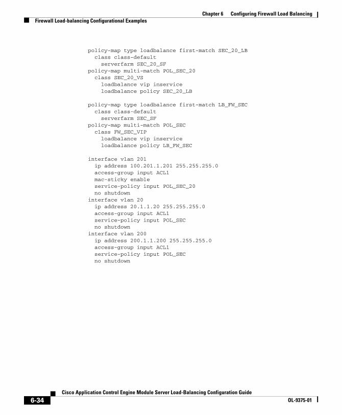
Chapter 6 Configuring Firewall Load BalancingFirewall Load-balancing Configurational Examples
policy-map type loadbalance first-match SEC_20_LB class class-default serverfarm SEC_20_SFpolicy-map multi-match POL_SEC_20 class SEC_20_VS loadbalance vip inservice loadbalance policy SEC_20_LB
policy-map type loadbalance first-match LB_FW_SEC class class-default serverfarm SEC_SFpolicy-map multi-match POL_SEC class FW_SEC_VIP loadbalance vip inservice loadbalance policy LB_FW_SEC
interface vlan 201 ip address 100.201.1.201 255.255.255.0 access-group input ACL1 mac-sticky enable service-policy input POL_SEC_20 no shutdowninterface vlan 20 ip address 20.1.1.20 255.255.255.0 access-group input ACL1 service-policy input POL_SEC no shutdowninterface vlan 200 ip address 200.1.1.200 255.255.255.0 access-group input ACL1 service-policy input POL_SEC no shutdown
6-34Cisco Application Control Engine Module Server Load-Balancing Configuration Guide
OL-9375-01

Chapter 6 Configuring Firewall Load BalancingFirewall Load-balancing Configurational Examples
Example of a Stealth Firewall ConfigurationThe following configuration example shows those portions of the running configuration that pertain to stealth FWLB. This configuration requires two ACE modules each residing in a different Catalyst 6500 switch.
ACE A Configuration—Stealth Firewall Load Balancing
access-list ACL1 line 10 extended permit ip any any
rserver FW_INSEC_1 ip address 101.0.201.100 inservicerserver FW_INSEC_2 ip address 101.0.202.100 inservicerserver FW_INSEC_3 ip address 101.0.203.100 inservice
serverfarm INSEC_SF transparent predictor hash address source 255.255.255.255 rserver FW_INSEC_1 inservice rserver FW_INSEC_2 inservice rserver FW_INSEC_3 inservice
class-map match-any FORWARD-VIP 10 match virtual-address 0.0.0.0 0.0.0.0 anyclass-map match-any FW_VIP 10 match virtual-address 200.1.1.1 255.255.0.0 anypolicy-map type loadbalance first-match FORWARD_FW_INSEC class class-default forwardpolicy-map type loadbalance first-match LB_FW_INSEC class class-default serverfarm INSEC_SFpolicy-map multi-match FORWARD_INSEC class FORWARD_VIP loadbalance vip inservice loadbalance policy FORWARD_FW_INSEC
6-35Cisco Application Control Engine Module Server Load-Balancing Configuration Guide
OL-9375-01

Chapter 6 Configuring Firewall Load BalancingFirewall Load-balancing Configurational Examples
policy-map multi-match POL_INSEC class FW_VIP loadbalance vip inservice loadbalance policy LB_FW_INSEC
interface vlan 100 ip address 100.100.1.10 255.255.0.0 access-group input ACL1 service-policy input POL_INSEC no shutdowninterface vlan 101 ip address 101.0.101.10 255.255.0.0 access-group input ACL1 service-policy input FORWARD_INSEC no shutdowninterface vlan 102 ip address 101.0.102.20 255.255.0.0 access-group input ACL1 service-policy input FORWARD_INSEC no shutdowninterface vlan 103 ip address 101.0.103.30 255.255.0.0 access-group input ACL1 service-policy input FORWARD_INSEC no shutdown
6-36Cisco Application Control Engine Module Server Load-Balancing Configuration Guide
OL-9375-01

Chapter 6 Configuring Firewall Load BalancingFirewall Load-balancing Configurational Examples
ACE B Configuration—Stealth Firewall Load Balancing.
access-list ACL1 line 10 extended permit ip any any
rserver host REAL1 ip address 20.1.1.1 inservicerserver host REAL2 ip address 20.1.1.2 inservicerserver host REAL3 ip address 20.1.1.3 inservice
rserver host FW_SEC_1 ip address 101.0.101.100 inservicerserver host FW_SEC_2 ip address 101.0.102.100 inservicerserver host FW_SEC_3 ip address 101.0.103.100 inservice
serverfarm SEC_20_SF rserver REAL1 inservice rserver REAL2 inservice rserver REAL3 inserviceserverfarm SEC_SF transparent predictor hash address destination 255.255.255.255 rserver FW_SEC_1 inservice rserver FW_SEC_2 inservice rserver FW_SEC_3 inservice
class-map match-any SEC_20_VS 10 match virtual-address 200.1.1.1 255.255.0.0 anyclass-map match-any FW_SEC_VIP 10 match virtual-address 0.0.0.0 0.0.0.0 any
6-37Cisco Application Control Engine Module Server Load-Balancing Configuration Guide
OL-9375-01

Chapter 6 Configuring Firewall Load BalancingFirewall Load-balancing Configurational Examples
policy-map type loadbalance first-match SEC_20_LB class class-default serverfarm SEC_20_SFpolicy-map type loadbalance first-match LB_FW_SEC class class-default serverfarm SEC_SFpolicy-map multi-match POL_SEC_20 class SEC_20_VS loadbalance vip inservice loadbalance policy SEC_20_LBpolicy-map multi-match POL_SEC class FW_SEC_VIP loadbalance vip inservice loadbalance policy LB_FW_SEC
interface vlan 201 ip address 101.0.201.10 255.255.0.0 access-group input ACL1 mac-sticky enable service-policy input POL_SEC_20 no shutdowninterface vlan 202 ip address 101.0.202.20 255.255.0.0 access-group input ACL1 mac-sticky enable service-policy input POL_SEC_20 no shutdowninterface vlan 203 ip address 101.0.203.30 255.255.0.0 access-group input ACL1 mac-sticky enable service-policy input POL_SEC_20 no shutdowninterface vlan 20 ip address 20.100.1.100 255.255.0.0 access-group input ACL1 service-policy input POL_SEC no shutdowninterface vlan 200 ip address 200.1.1.200 255.255.255.0 access-group input ACL1 service-policy input POL_SEC no shutdown
6-38Cisco Application Control Engine Module Server Load-Balancing Configuration Guide
OL-9375-01

Cisco Application Control Engine Module Server LOL-9375-01
A P P E N D I X A
Using Toolkit Command Language (TCL) Scripts with the ACEYou can copy, upload, and execute Toolkit Command Language (TCL) scripts on the ACE. TCL is a widely used scripting language within the networking community. TCL also has large libraries of developed scripts that can easily be found from various sites. Using TCL scripts, you can write TCL scripts for customized health probes. The ACE also supports UDP socket functions.
Note The ACE can simultaneously execute only 200 scripted probe instances. When this limit is exceeded, the show probe detail command displays the “Out-of Resource: Max. script-instance limit reached” error message in the Last disconnect err field and the out-of-sockets counter increments.
This chapter provides information on scripts and contains the following sections:
• Scripts Overview
• Probe Script Quick Start
• Copying and Loading Scripts on the ACE
• Configuring Health Probes for Scripts
• Writing Probe Scripts
• Displaying Script Information
• Debugging Probe Scripts
A-1oad-Balancing Configuration Guide

Appendix A Using Toolkit Command Language (TCL) Scripts with the ACEScripts Overview
Scripts OverviewThe ACE supports several specific types of health probes (for example HTTP, TCP, or ICMP health probes) when you need to use a diverse set of applications and health probes to administer your network. The basic health probe types supported in the current ACE software release may not support the specific probing behavior that your network requires. To support a more flexible health-probing functionality, the ACE allows you to upload and execute TCL scripts on the ACE.
The TCL interpreter code in the ACE is based on Release 8.44 of the standard TCL distribution. You can create a script to configure health probes. Script probes operate similar to other health probes available in the ACE software. As part of a script probe, the ACE executes the script periodically, and the exit code that is returned by the executing script indicates the relative health and availability of specific real servers. For information on health probes, see Chapter 4, Configuring Health Monitoring.
For your convenience, the following sample scripts for the ACE are available to support the TCL feature and are supported by Cisco TAC:
• CHECKPORT_STD_SCRIPT
• ECHO_PROBE_SCRIPT
• FINGER_PROBE_SCRIPT
• FTP_PROBE_SCRIPT
• HTTP_PROBE_SCRIPT
• HTTPCONTENT_PROBE
• HTTPHEADER_PROBE
• HTTPPROXY_PROBE
• IMAP_PROBE
• LDAP_PROBE
• MAIL_PROBE
• POP3_PROBE
• PROBENOTICE_PROBE
• RTSP_PROBE
A-2Cisco Application Control Engine Module Server Load-Balancing Configuration Guide
OL-9375-01
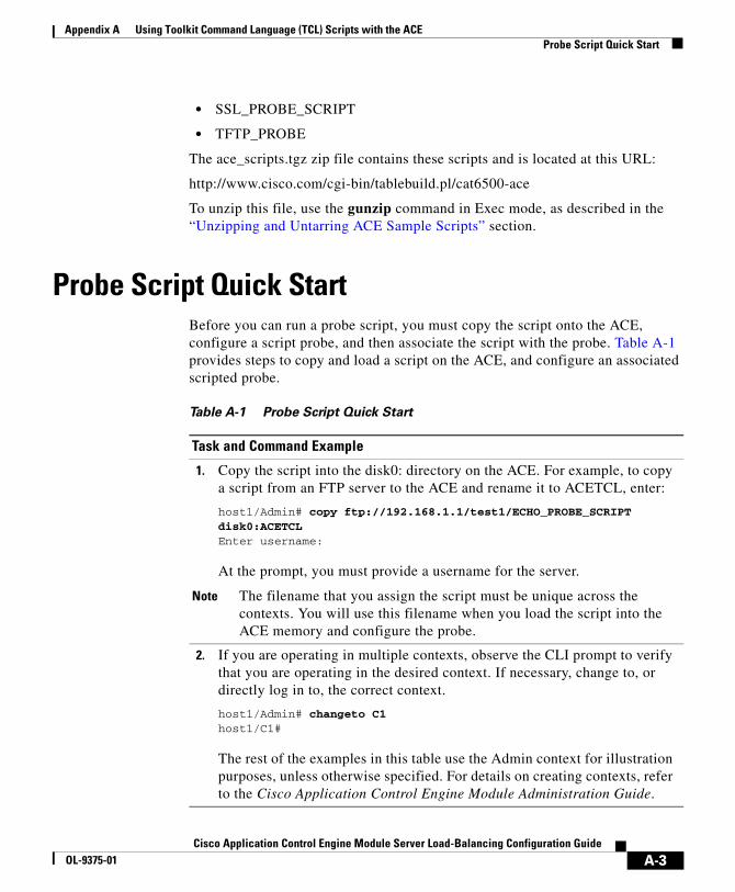
Appendix A Using Toolkit Command Language (TCL) Scripts with the ACEProbe Script Quick Start
• SSL_PROBE_SCRIPT
• TFTP_PROBE
The ace_scripts.tgz zip file contains these scripts and is located at this URL:
http://www.cisco.com/cgi-bin/tablebuild.pl/cat6500-ace
To unzip this file, use the gunzip command in Exec mode, as described in the “Unzipping and Untarring ACE Sample Scripts” section.
Probe Script Quick StartBefore you can run a probe script, you must copy the script onto the ACE, configure a script probe, and then associate the script with the probe. Table A-1 provides steps to copy and load a script on the ACE, and configure an associated scripted probe.
Table A-1 Probe Script Quick Start
Task and Command Example
1. Copy the script into the disk0: directory on the ACE. For example, to copy a script from an FTP server to the ACE and rename it to ACETCL, enter:
host1/Admin# copy ftp://192.168.1.1/test1/ECHO_PROBE_SCRIPT disk0:ACETCLEnter username:
At the prompt, you must provide a username for the server.
Note The filename that you assign the script must be unique across the contexts. You will use this filename when you load the script into the ACE memory and configure the probe.
2. If you are operating in multiple contexts, observe the CLI prompt to verify that you are operating in the desired context. If necessary, change to, or directly log in to, the correct context.
host1/Admin# changeto C1host1/C1#
The rest of the examples in this table use the Admin context for illustration purposes, unless otherwise specified. For details on creating contexts, refer to the Cisco Application Control Engine Module Administration Guide.
A-3Cisco Application Control Engine Module Server Load-Balancing Configuration Guide
OL-9375-01
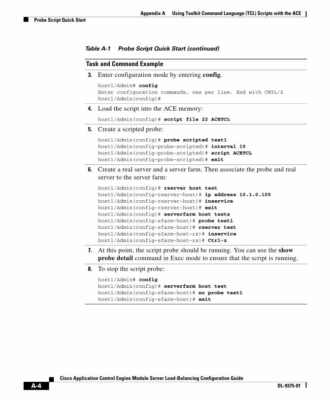
Appendix A Using Toolkit Command Language (TCL) Scripts with the ACEProbe Script Quick Start
3. Enter configuration mode by entering config.
host1/Admin# configEnter configuration commands, one per line. End with CNTL/Zhost1/Admin(config)#
4. Load the script into the ACE memory:
host1/Admin(config)# script file 22 ACETCL
5. Create a scripted probe:
host1/Admin(config)# probe scripted test1 host1/Admin(config-probe-scripted)# interval 10host1/Admin(config-probe-scripted)# script ACETCLhost1/Admin(config-probe-scripted)# exit
6. Create a real server and a server farm. Then associate the probe and real server to the server farm:
host1/Admin(config)# rserver host testhost1/Admin(config-rserver-host)# ip address 10.1.0.105host1/Admin(config-rserver-host)# inservicehost1/Admin(config-rserver-host)# exithost1/Admin(config)# serverfarm host testshost1/Admin(config-sfarm-host)# probe test1host1/Admin(config-sfarm-host)# rserver testhost1/Admin(config-sfarm-host-rs)# inservicehost1/Admin(config-sfarm-host-rs)# Ctrl-z
7. At this point, the script probe should be running. You can use the show probe detail command in Exec mode to ensure that the script is running.
8. To stop the script probe:
host1/Admin# confighost1/Admin(config)# serverfarm host testhost1/Admin(config-sfarm-host)# no probe test1host1/Admin(config-sfarm-host)# exit
Table A-1 Probe Script Quick Start (continued)
Task and Command Example
A-4Cisco Application Control Engine Module Server Load-Balancing Configuration Guide
OL-9375-01

Appendix A Using Toolkit Command Language (TCL) Scripts with the ACECopying and Loading Scripts on the ACE
Copying and Loading Scripts on the ACEYou load scripts onto the ACE through script files. A script file contains only one script. The ACE allows the configuration of 256 script files.
When using scripts on the ACE, the following considerations apply:
• Each script is always identified by its unique name as defined when copying the script file into the ACE disk0: filesystem. The script name must be unique across contexts.
• During probe configuration, you can assign a script to a probe. If the script is unavailable at that time, the probe attempts to execute the script and returns an error code. If this situation occurs, a syslog message displays to indicate the probe failure and why the probe failed. If the script is unavailable due to an error when loading the script, a syslog message would indicate the script load failure. You can also use the show script command to display the exit codes. For a list of exit codes, see Table A-7.
• To change a script that is already loaded into memory, you must unload and then reload the script. For information on loading a script file, see the “Loading Scripts into the ACE Memory” section. For information on reloading a script, see the “Removing Scripts from ACE Memory” section.
After the script is changed in memory, the ACE applies the changes automatically the next time that the script executes. The command line arguments specified during probe configuration still apply after the reloading of the script.
Note Because the ACE does not replicate probe scripts to the standby in a redundant configuration, you must copy the scripts from the active ACE to the standby ACE. Otherwise, configuration synchronization does not work properly.
This section contains the following topics:
• Copying Scripts to the ACE
• Unzipping and Untarring ACE Sample Scripts
• Loading Scripts into the ACE Memory
• Removing Scripts from ACE Memory
• Reloading Modified Scripts in ACE Memory
A-5Cisco Application Control Engine Module Server Load-Balancing Configuration Guide
OL-9375-01

Appendix A Using Toolkit Command Language (TCL) Scripts with the ACECopying and Loading Scripts on the ACE
Copying Scripts to the ACETo copy a script from a server to the ACE disk0: filesystem, use the copy command in Exec mode. Note that you can also copy the file from the supervisor to the ACE.
Because of virtualization, by default, a script file is copied into the directory for context that you are currently accessing. Thus, a script file in one context cannot be seen from another context. For details about virtualization, refer to the Cisco Application Control Engine Module Virtualization Configuration Guide. The syntax of this command is:
copy [ftp://server/path | tftp://server[:port]/path | sftp://[username@]server/path] disk0:filename
The keywords and arguments are:
• ftp://server/path—Specifies the File Transfer Protocol (FTP) network server and the source location of the script file including its filename.
• sftp:[//[username@]server][/path]—Specifies the Secure Trivial File Transfer Protocol (SFTP) network server and the source location of the script file including its filename.
• tftp: //server[:port]/path]—Specifies the Trivial File Transfer Protocol (TFTP) network server and the source location of the script file including its filename.
• disk0:filename—Specifies the destination filename for the script on the ACE disk0: filesystem. If you do not enter a filename, you are prompted to enter a filename or accept the source filename. You will use this filename when you load the script into the ACE memory and configure the probe.
Note The filename that you assign to the script must be unique across the contexts.
For example, to copy a script from an FTP server to the ACE, enter:
host1/Admin# copy ftp://192.168.1.1/test1/FTP_PROBE_SCRIPT disk0:ftp1.tclEnter username:
At the prompt, you must provide a username for the server.
A-6Cisco Application Control Engine Module Server Load-Balancing Configuration Guide
OL-9375-01

Appendix A Using Toolkit Command Language (TCL) Scripts with the ACECopying and Loading Scripts on the ACE
You can also copy the zipped sample scripts file for the ACE onto disk0:. After you copy the zipped file, use the gunzip command in Exec mode to unzip its contents. For information on using this command, see the “Unzipping and Untarring ACE Sample Scripts” section.
Unzipping and Untarring ACE Sample ScriptsSample scripts for the ACE are available to support the TCL feature. All of these scripts are provided in a zipped file which contains a .tar file. After you copy the zip file to the ACE, you need to unzip it and then untar it. When you untar the file, the ACE automatically creates an ace_scripts directory and places all of the individual scripts in it.
To unzip the sample scripts file, use the gunzip command in Exec mode. The syntax for this command is:
gunzip disk0:[path/]filename.tgz
The filename argument is the name of the zipped scripts file.
For example, to unzip the ace_scripts.tgz scripts file, enter:
host1/Admin# gunzip disk0:ace_scripts.tgz
The ACE unzips the file and places the ace_scripts.tar file in the disk0: filesystem.
To untar all of the script files from the ace_scripts.tar file, use the untar command in Exec mode. The syntax for the command is:
untar disk0:[path/]filename
The filename argument identifies the name of the .tar file in the disk0: filesystem. The filename must end with a .tar extension.
For example, to untar all of the script files into the ace_scripts directory in the disk0: filesystem, enter:
host1/Admin# untar disk0:ace_scripts.tar
To view the scripts in the ace_scripts directory, use the dir command in Exec mode. For example, enter:
host1/Admin# dir disk0:ace_scripts/
A-7Cisco Application Control Engine Module Server Load-Balancing Configuration Guide
OL-9375-01

Appendix A Using Toolkit Command Language (TCL) Scripts with the ACECopying and Loading Scripts on the ACE
Before you can load a sample script into memory, you must copy the script out of the ace_scripts directory into the disk0: directory. Use the copy disk0: command. For example, to copy the ftp1.tcl script from the ace_scripts directory to the disk0: directory, enter:
host1/Admin# copy disk0:ace_scripts/ftp1.tcl disk0:ftp1.tcl
Loading Scripts into the ACE MemoryTo load the script into memory on the ACE and enable it for use, use the script file command in configuration mode. The syntax of this command is:
script file index script_name
The arguments are:
• index—An index number for the script file. The index number will be associated with the script name. The number must be unique across the contexts. Enter a number from 1 to 255.
• script_name—The name of the script on the disk0: filesystem.
Note To load a script into memory, the script must be in the disk0: directory. The ACE does not load script files in a disk0: subdirectory.
For example, to load a script into memory:
host1/Admin(config)# script file 22 ftp1.tcl
To run the script or create a health probe using that script, use the script name you configured; not the script file from which the script was loaded.
Removing Scripts from ACE MemoryAfter a script file has been loaded, the scripts in that file exist in the ACE independent of the file from which that script was loaded. To remove a script from memory and the running configuration, use the no script file command in configuration mode. The syntax of this command is:
no script file index
A-8Cisco Application Control Engine Module Server Load-Balancing Configuration Guide
OL-9375-01
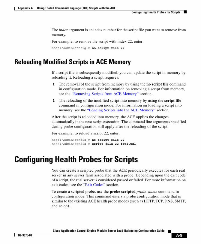
Appendix A Using Toolkit Command Language (TCL) Scripts with the ACEConfiguring Health Probes for Scripts
The index argument is an index number for the script file you want to remove from memory.
For example, to remove the script with index 22, enter:
host1/Admin(config)# no script file 22
Reloading Modified Scripts in ACE MemoryIf a script file is subsequently modified, you can update the script in memory by reloading it. Reloading a script requires:
1. The removal of the script from memory by using the no script file command in configuration mode. For information on removing a script from memory, see the “Removing Scripts from ACE Memory” section.
2. The reloading of the modified script into memory by using the script file command in configuration mode. For information on loading a script into memory, see the “Loading Scripts into the ACE Memory” section.
After the script is reloaded into memory, the ACE applies the changes automatically in the next script execution. The command line arguments specified during probe configuration still apply after the reloading of the script.
For example, to reload a script 22, enter:
host1/Admin(config)# no script file 22host1/Admin(config)# script file 22 ftp1.tcl
Configuring Health Probes for ScriptsYou can create a scripted probe that the ACE periodically executes for each real server in any server farm associated with a probe. Depending upon the exit code of a script, the real server is considered passed or failed. For more information on exit codes, see the “Exit Codes” section.
To create a scripted probe, use the probe scripted probe_name command in configuration mode. This command enters a probe configuration mode that is similar to the existing ACE health probe modes (such as HTTP, TCP, DNS, SMTP, and so on).
A-9Cisco Application Control Engine Module Server Load-Balancing Configuration Guide
OL-9375-01
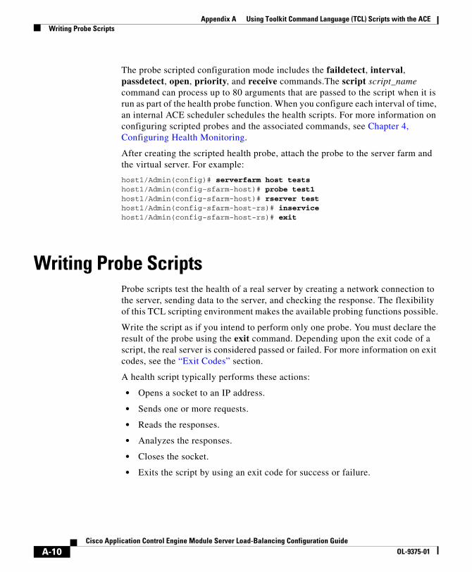
Appendix A Using Toolkit Command Language (TCL) Scripts with the ACEWriting Probe Scripts
The probe scripted configuration mode includes the faildetect, interval, passdetect, open, priority, and receive commands.The script script_name command can process up to 80 arguments that are passed to the script when it is run as part of the health probe function. When you configure each interval of time, an internal ACE scheduler schedules the health scripts. For more information on configuring scripted probes and the associated commands, see Chapter 4, Configuring Health Monitoring.
After creating the scripted health probe, attach the probe to the server farm and the virtual server. For example:
host1/Admin(config)# serverfarm host testshost1/Admin(config-sfarm-host)# probe test1host1/Admin(config-sfarm-host)# rserver testhost1/Admin(config-sfarm-host-rs)# inservicehost1/Admin(config-sfarm-host-rs)# exit
Writing Probe ScriptsProbe scripts test the health of a real server by creating a network connection to the server, sending data to the server, and checking the response. The flexibility of this TCL scripting environment makes the available probing functions possible.
Write the script as if you intend to perform only one probe. You must declare the result of the probe using the exit command. Depending upon the exit code of a script, the real server is considered passed or failed. For more information on exit codes, see the “Exit Codes” section.
A health script typically performs these actions:
• Opens a socket to an IP address.
• Sends one or more requests.
• Reads the responses.
• Analyzes the responses.
• Closes the socket.
• Exits the script by using an exit code for success or failure.
A-10Cisco Application Control Engine Module Server Load-Balancing Configuration Guide
OL-9375-01

Appendix A Using Toolkit Command Language (TCL) Scripts with the ACEWriting Probe Scripts
This section provides information to assist you when you write a probe script. The topics include:
• TCL Script Commands Supported on the ACE
• Environment Variables
• Exit Codes
• Example for Writing a Probe Script
TCL Script Commands Supported on the ACEThe ACE TCL script feature is based on the TCL 8.44 source distribution software. Table A-2 lists the TCL commands that are supported by ACE.
Table A-2 TCL Commands Supported by the ACE
Command
Generic TCL Commands1
append array binary break
case catch concat continue
encoding error eval exit
expr fblocked for foreach
format gets glob global
if incr info join
lappend lindex linsert list
llength lrange lreplace lsearch
lset lsort namespace proc
regexp regsub rename return
scan set split string
subst switch unset uplevel
upvar variable while
Time-Related Commands
after clock time
A-11Cisco Application Control Engine Module Server Load-Balancing Configuration Guide
OL-9375-01
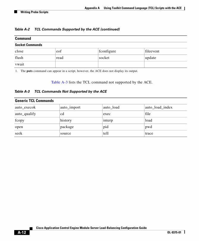
Appendix A Using Toolkit Command Language (TCL) Scripts with the ACEWriting Probe Scripts
Table A-3 lists the TCL command not supported by the ACE.
Table A-3 TCL Commands Not Supported by the ACE
Generic TCL Commands
auto_execok auto_import auto_load auto_load_index
auto_qualify cd exec file
fcopy history interp load
open package pid pwd
seek source tell trace
Socket Commands
close eof fconfigure fileevent
flush read socket update
vwait
1. The puts command can appear in a script, however, the ACE does not display its output.
Table A-2 TCL Commands Supported by the ACE (continued)
Command
A-12Cisco Application Control Engine Module Server Load-Balancing Configuration Guide
OL-9375-01

Appendix A Using Toolkit Command Language (TCL) Scripts with the ACEWriting Probe Scripts
Table A-4 lists the TCL command specific to the ACE.
Table A-4 ACE Specific TCL Commands
Command Definition
gset varname value Allows you to preserve the state of a probe by setting a variable that is global to all probe threads running from the same script.
Variables in a probe script are only visible within one probe thread. Each time a probe exits, all variables are gone. For example, if a probe script contains a 'gset x 1 ; incr x', variable x would increase by 1 for each probe attempt.
• To set the value of variable from script, set var or $var.
• To reset the value of variable from script, unset var.
• To display the gset value, have the script place this value in the exit message . Then you can use the show script command to display the exit message. Make sure that the script does not overwrite the exit message with another value before it exits. For information on the show script command, see the “Displaying the Statistics for an Active Script” section.
The UDP command set allows Scotty-based TCL scripts to run on the ACE. Scotty is the name of a software package that allows you to implement site-specific network management soft ware using high-level, string-based APIs. The TCL UDP command reference is located at this URL:
http://wwwhome.cs.utwente.nl/~schoenw/scotty/
A-13Cisco Application Control Engine Module Server Load-Balancing Configuration Guide
OL-9375-01

Appendix A Using Toolkit Command Language (TCL) Scripts with the ACEWriting Probe Scripts
Table A-5 lists the UDP commands used by the ACE.
Table A-5 UDP Commands
Command Definition
udp_binary send handle [host port] message
Sends binary data containing a message to the destination specified by host and port. The host and port arguments may not be used if the UDP handle is already connected to a transport endpoint. If the UDP handle is not connected, you must use these optional arguments to specify the destination of the datagram.
udp bind handle readable [script] udp bind handle writable [script]
Allows binding scripts to a UDP handle. A script is evaluated once the UDP handle becomes either readable or writable, depending on the third argument of the udp bind command. The script currently bound to a UDP handle can be retrieved by calling the udp bind command without a script argument. Bindings are removed by binding an empty string.
udp close handle Closes the UDP socket associated with handle.
udp connect host port Opens a UDP datagram socket and connects it to a port on a remote host. A connected UDP socket only allows sending messages to a single destination. This usually allows shortening the code because there is no need to specify the destination address for each udp send command on a connected UDP socket. The command returns a UDP handle.
udp info [handle] Without the handle argument, this command returns a list of all existing UDP handles. Information about the state of a UDP handle can be obtained by supplying a valid UDP handle. The result is a list containing the source IP address, the source port, the destination IP address and the destination port.
udp open [port] Opens a UDP datagram socket and returns a UDP handle. The socket is bound to given port number or name. An unused port number is used if the port argument is missing.
A-14Cisco Application Control Engine Module Server Load-Balancing Configuration Guide
OL-9375-01

Appendix A Using Toolkit Command Language (TCL) Scripts with the ACEWriting Probe Scripts
Environment VariablesHealth probe scripts have access to many configured items through a predefined TCL array. The most common use of this array is to find the current real server IP addresses of the suspect during any particular launch of the script.
Whenever the ACE executes a script probe, a special array called scriptprobe_env is passed to the script. This array holds important parameters that may be used by the script.
Table A-6 lists the members of the scriptprobe_env array.
udp receive handle Receives a datagram from the UDP socket associated with the handle. This command blocks until a datagram is ready to be received.
udp send handle [host port] message Sends ASCII data containing a message to the destination specified by host and port. The host and port arguments may not be used if the UDP handle is already connected to a transport endpoint. If the UDP handle is not connected, you must use these optional arguments to specify the destination of the datagram.
Table A-5 UDP Commands (continued)
Command Definition
Table A-6 Member list for the scriptprobe_env Array
Member name Content
realIP Suspect IP address
realPort Suspect IP port
intervalTimeout Configured probe interval in seconds
openTimeout Configured socket open timeout for this probe (tbd)
recvTimeout Configured socket receive timeout for this probe
failedTimeout Configure failed timeout
retries Configured retry count
A-15Cisco Application Control Engine Module Server Load-Balancing Configuration Guide
OL-9375-01

Appendix A Using Toolkit Command Language (TCL) Scripts with the ACEWriting Probe Scripts
Exit CodesThe probe script uses exit codes to signify various internal conditions. The exit code information can help you troubleshoot your scripts if they do not operate correctly. A probe script indicates the relative health and availability of a real server using the exit code of the script. By calling exit 30001, a script indicates that the server successfully responded to the probe. Calling exit 30002 indicates that the server did not respond correctly to the health probe.
For example, if a probe script fails and exits with 30002, the corresponding server is marked as PROBE_FAILED and is temporarily disabled from the server farm. The ACE continues to probe the server. When the probe successfully reconnects and exits with 30001, the ACE marks the server status as OPERATIONAL and enables the server from the server farm again. The exit 30001 must occur the number of failedRetries times before the server is marked as OPERATIONAL. See the previous section on environmental variables for further information on the failedRetries member name.
healthStatus Current suspect health status
contextID The ID for the context running this script
failedRetries Consecutive successful retries on a failed server before marking it as passed
isRouted Boolean to determine if this IP address is a routed address
pid Process identifier of the TCL process
runID Pointer to the event structure (em_event_t)
Table A-6 Member list for the scriptprobe_env Array (continued)
Member name Content
A-16Cisco Application Control Engine Module Server Load-Balancing Configuration Guide
OL-9375-01

Appendix A Using Toolkit Command Language (TCL) Scripts with the ACEWriting Probe Scripts
These situations can cause a script to fail and mark the suspect PROBE_FAILED:
• TCL errors—Occurs when scripts contain errors that are caught by the TCL interpreter, for example, a syntax error.
The syntax error message is stored in the special variable erroInfo and can be viewed using the show script command in Exec mode. Another example of TCL errors would cause the TCL interpreter to abort and call panic.
• A stopped script—Caused by an infinite loop and wait indefinitely for a response. Each script must complete its task within the configured time interval. If the script does not complete its task, the script controller terminates the script, and the suspect is failed implicitly.
• Error conditions—Occurs when a connection timeout or a peer-refused connection is also treated as an implicit failure.
Table A-7 shows all exit codes used in the ACE.
Table A-7 ACE Exit Codes
Exit Code Description/Message
30001 Probe successful (no message)
30002 Probe error: Server did not respond as expected
30003 Internal error: Fork failed for TCL script
30004 Internal error: Script probe terminated due to timeout
30005 Internal error: TCL interpreter PANIC (interpreter problem)
30006 Internal error: Script error
30007 Internal error: Script-file lookup failed or empty buffer
30008 Internal error: Failed to allocate memory for TCL_wt (worker thread) qnode
30009 Internal error: Unknown script error
30010 Internal error: Out of sockets for the TCL script
30011 Internal error: Unable to read persistent variable table
30012 Internal error: PData (probe data) pointer is null
A-17Cisco Application Control Engine Module Server Load-Balancing Configuration Guide
OL-9375-01

Appendix A Using Toolkit Command Language (TCL) Scripts with the ACEWriting Probe Scripts
Example for Writing a Probe ScriptThis example shows how a script is written to probe an HTTP server using a health script:
# get the IP address of the real server from a predefined global array# scriptprobe_envset ip $scriptprobe_env(realIP)set port 80set url "GET /index.html HTTP/1.0\n\n"
# Open a socket to the server. This creates a TCP connection to the# real serverset exit_msg "opening socket"set sock [socket $ip $port]fconfigure $sock -buffering none -eofchar {}
# Wait for the response from the server and read that in variable lineset exit_msg "receiving response"set line [ read $sock ]
# Parse the responseif { [ regexp "HTTP/1.. (\[0-9\]+) " $line match status ] }
# Close the socket. Application MUST close the socket once the # request/response is over. # This allows other applications and tcl scripts to make# a good use of socket resource. Health monitoring is allowed to open# only 200 sockets simultaneously.set exit_msg "closing socket"close $sock
# decide the exit code to return to control module.# If the status code is OK then script MUST do exit 30001# to signal successful completion of a script probe.# In this example any other status code means failure.# User must do exit 30002 when a probe has failed.if { $status == 200 } { set exit_msg "probe success" exit 30001} else { set exit_msg "probe fail : can't find status code" exit 30002
A-18Cisco Application Control Engine Module Server Load-Balancing Configuration Guide
OL-9375-01

Appendix A Using Toolkit Command Language (TCL) Scripts with the ACEDisplaying Script Information
Displaying Script InformationThe following sections provide information for displaying scripted probe and script information:
• Displaying ACE Script and Scripted Probe Configuration
• Displaying Scripted Probe Information
• Displaying Global Scripted Probe Statistics
• Displaying the Statistics for an Active Script
• Displaying the Script Contents
Displaying ACE Script and Scripted Probe ConfigurationTo display configuration information for scripts and scripted probes on the ACE, use the show running-config command in Exec mode. For example, enter:
switch/Admin# show running-configGenerating configuration....
logging enableboot system image:
script file 200 ftp1.tcl
probe scripted bts_test_probe interval 10 receive 8 script test.tcl
rserver host bts_test_rserver ip address 10.86.209.1 probe bts_test_probe inservice
snmp-server user www Network-Monitor snmp-server user admin Network-Monitor
context Admin...
A-19Cisco Application Control Engine Module Server Load-Balancing Configuration Guide
OL-9375-01

Appendix A Using Toolkit Command Language (TCL) Scripts with the ACEDisplaying Script Information
Displaying Scripted Probe InformationTo display configuration and probe result information about scripted probes, use the show probe command in Exec mode. The syntax of this command is:
show probe scripted_probe_name [detail]
The argument and option are:
• scripted_probe_name—Displays the information for the specified scripted probe name
• detail—(Optional) Displays detailed probe information including configuration information and statistics
If you do not enter a probe name, this command shows a summary of information for all configured probes.
For example, to view the SCRIPT-1 scripted probe and detailed information, enter:
host1/Admin# show probe SCRIPT-1 detail
Table A-8 describes the fields in the show probe command output for a scripted probe.
Table A-8 Field Descriptions for the show probe Command for a Scripted
Probe
Field Description
probe Name of the probe.
type Probe type.
description Configured string that describes the probe.
port Port number that the probe uses. By default, the probe uses the port number based on its type.
address Not used for scripted probes.
addr type Not used for scripted probes.
interval Time interval in seconds that the ACE sends probes to a server marked as passed.
A-20Cisco Application Control Engine Module Server Load-Balancing Configuration Guide
OL-9375-01
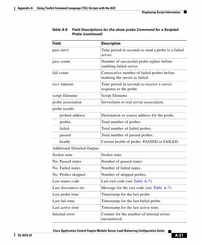
Appendix A Using Toolkit Command Language (TCL) Scripts with the ACEDisplaying Script Information
pass intvl Time period in seconds to send a probe to a failed server.
pass count Number of successful probe replies before enabling failed server.
fail count Consecutive number of failed probes before marking the server as failed.
recv timeout Time period in seconds to receive a server response to the probe.
script filename Script filename.
probe association Serverfarm or real server association.
probe results
probed-address Destination or source address for the probe.
probes Total number of probes.
failed Total number of failed probes.
passed Total number of passed probes.
health Current health of probe: PASSED or FAILED.
Additional Detailed Output:
Socket state Socket state.
No. Passed states Number of passed states.
No. Failed states Number of failed states.
No. Probes skipped Number of skipped probes.
Last status code Last exit code (see Table A-7).
Last disconnect err Message for the exit code (see Table A-7).
Last probe time Timestamp for the last probe.
Last fail time Timestamp for the last failed probe.
Last active time Timestamp for the last active time.
Internal error Counter for the number of internal errors encountered.
Table A-8 Field Descriptions for the show probe Command for a Scripted
Probe (continued)
Field Description
A-21Cisco Application Control Engine Module Server Load-Balancing Configuration Guide
OL-9375-01

Appendix A Using Toolkit Command Language (TCL) Scripts with the ACEDisplaying Script Information
Displaying Global Scripted Probe StatisticsTo display the global statistics for all scripted probe, use the show stats probe type scripted command in Exec mode. For example, enter:
host1/Admin# show stats probe type scripted
Table A-9 describes the fields in the show stats probe type scripted command output.
Table A-9 Field Descriptions for the show stats probe type scripted command
Field Description
Total probes sent Total number of probes sent by all scripted probes.
Total send failures Total number of send failures for all scripted probes. These failures are due to internal errors. For more information, see the last disconnect error field displayed by the show probe command.
Total probes passed Total number of passed probes for all scripted probes.
Total probes failed Total number of failed probes for all scripted probes.
Total connect errors Total number of connection errors for all scripted probes.
Total conns refused Total number of connections refused for all scripted probes.
Total RST received Total number of resets received by all scripted probes.
Total open timeouts Total number of open timeouts for all scripted probes.
Total receive timeouts Total number of time outs received by all scripted probes.
A-22Cisco Application Control Engine Module Server Load-Balancing Configuration Guide
OL-9375-01

Appendix A Using Toolkit Command Language (TCL) Scripts with the ACEDisplaying Script Information
Displaying the Statistics for an Active ScriptTo display the statistics for a script file active on the ACE including exit codes and exit messages, use the show script command from Exec mode. The syntax for this command is:
show script script_name probe_name [rserver_name [port_name]] [serverfarm sfarm_name]
The arguments and options are:
• script_name—The name of the script
• probe_name—The name of the scripted probe associated the script
• rserver_name [port_name]—(Optional) Specifies the name of the real server and optional port number using the scripted probe
• serverfarm sfarm_name—The name of the server farm using the scripted probe
For example, to display the statistics for the ECHO_PROBE_SCRIPT script for the SCRIPT1 probe:
host1/Admin# show script ECHO_PROBE_SCRIPT SCRIPT1
Table A-10 describes the fields in the show script command output.
Table A-10 Field Descriptions for the show script command
Field Description
Script Name of the script.
Scripted probe Probe associated with the script.
Probe-association(s): (count=number)
Total number of real servers and server farms associated with the scripted probe.
Rserver/Serverfarm Name of the real server or server farm for the script statistics.
Exit code Current exit code for the script. See Table A-7 for information on exit codes.
Child PID Child process identifier for the script.
Exit message Value of the TCL gset variable from the script.
A-23Cisco Application Control Engine Module Server Load-Balancing Configuration Guide
OL-9375-01
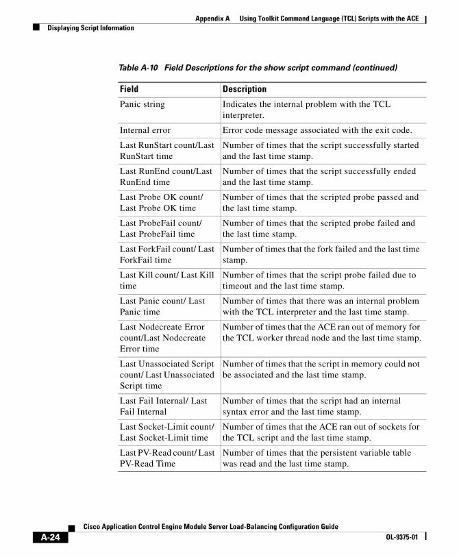
Appendix A Using Toolkit Command Language (TCL) Scripts with the ACEDisplaying Script Information
Panic string Indicates the internal problem with the TCL interpreter.
Internal error Error code message associated with the exit code.
Last RunStart count/Last RunStart time
Number of times that the script successfully started and the last time stamp.
Last RunEnd count/Last RunEnd time
Number of times that the script successfully ended and the last time stamp.
Last Probe OK count/ Last Probe OK time
Number of times that the scripted probe passed and the last time stamp.
Last ProbeFail count/ Last ProbeFail time
Number of times that the scripted probe failed and the last time stamp.
Last ForkFail count/ Last ForkFail time
Number of times that the fork failed and the last time stamp.
Last Kill count/ Last Kill time
Number of times that the script probe failed due to timeout and the last time stamp.
Last Panic count/ Last Panic time
Number of times that there was an internal problem with the TCL interpreter and the last time stamp.
Last Nodecreate Error count/Last Nodecreate Error time
Number of times that the ACE ran out of memory for the TCL worker thread node and the last time stamp.
Last Unassociated Script count/ Last Unassociated Script time
Number of times that the script in memory could not be associated and the last time stamp.
Last Fail Internal/ Last Fail Internal
Number of times that the script had an internal syntax error and the last time stamp.
Last Socket-Limit count/ Last Socket-Limit time
Number of times that the ACE ran out of sockets for the TCL script and the last time stamp.
Last PV-Read count/ Last PV-Read Time
Number of times that the persistent variable table was read and the last time stamp.
Table A-10 Field Descriptions for the show script command (continued)
Field Description
A-24Cisco Application Control Engine Module Server Load-Balancing Configuration Guide
OL-9375-01
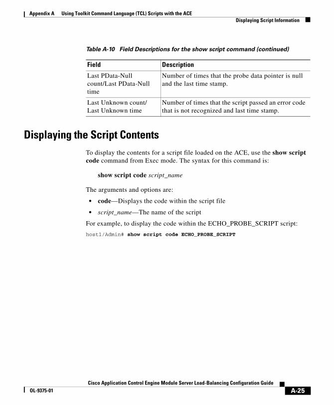
Appendix A Using Toolkit Command Language (TCL) Scripts with the ACEDisplaying Script Information
Displaying the Script ContentsTo display the contents for a script file loaded on the ACE, use the show script code command from Exec mode. The syntax for this command is:
show script code script_name
The arguments and options are:
• code—Displays the code within the script file
• script_name—The name of the script
For example, to display the code within the ECHO_PROBE_SCRIPT script:
host1/Admin# show script code ECHO_PROBE_SCRIPT
Last PData-Null count/Last PData-Null time
Number of times that the probe data pointer is null and the last time stamp.
Last Unknown count/ Last Unknown time
Number of times that the script passed an error code that is not recognized and last time stamp.
Table A-10 Field Descriptions for the show script command (continued)
Field Description
A-25Cisco Application Control Engine Module Server Load-Balancing Configuration Guide
OL-9375-01

Appendix A Using Toolkit Command Language (TCL) Scripts with the ACEDebugging Probe Scripts
Debugging Probe Scripts To debug a script probe, you can do the following:
• Use the EXIT_MSG variable in the script. Each probe suspect contains its own EXIT_MSG variable. This variable allows you to trace the status of a script and check the status of the probe.
This example shows how to use the EXIT_MSG variable in a script:
set EXIT_MSG "before opening socket"set s [ socket $ip $port]set EXIT_MSG " before receive string"gets $s set EXIT_MSG "before close socket"close $s
If a probe suspect fails when receiving the message, you should see EXIT_MSG = before you receive the string. You can view the EXIT_MSG variable with the show script command in Exec mode.
• Use the show probe command in Exec mode to view the current active probe suspects in the system. For more information on this command, see the “Displaying Script Information” section.
• Use the show script command in Exec mode to view:
– The last exit status with the exit code number.
– The internal error that is generated by the TCL compiler. When the script has a TCL runtime error, the TCL interpreter stops running the script and the ACE displays this error.
– The EXIT_MSG variable value of the TCL gset command from the script.
A-26Cisco Application Control Engine Module Server Load-Balancing Configuration Guide
OL-9375-01

Cisco Application Control Engine Module Server OL-9375-01
I N D E X
A
asymmetric routing 1-7
B
backup
server, configuring 2-27
server farm, configuring 2-30
server farm, sticky 5-6
C
case sensitivity matching 3-37
cipher suite, configuring for HTTPS probes 4-24
class map
configuring 3-1, 3-42
description, entering 3-43
Layer 7 for SLB configuration 3-11
real servers, use with 2-2
SLB overview 3-2
configuration
standard firewall al examples 6-33
standard firewall examples 6-31
stealth firewall examples 6-35, 6-37
stickiness example 5-46
configuration quick start 5-8
configurations
probe, displaying 4-40
real server, displaying 2-31
server farm, displaying 2-37
stickiness, displaying 5-42
connection failure, specifying server farm action 2-17
connection keepalive. See HTTP persistence rebalance
connections
clearing for real servers 2-36
displaying for real servers 2-34
displaying for server farms 2-40
connection termination, TCP 4-12
cookie
client 5-4
configuring stickiness 5-16
insertion 5-24
length 3-39, 5-25
match criteria 3-13
maximum bytes to parse 3-38
IN-1Load-Balancing Configuration Guide
Index
offset 5-24
sticky client identification 5-4
credentials (mailbox), configuring for IMAP probes 4-33
D
database entries
sticky, clearing 5-46
sticky, displaying 5-42
delimiters, URL 3-37
destination IP address 2-22, 2-35, 2-41, 3-2, 3-30, 5-3, 5-8, 5-11, 5-14, 6-3
destination server status code, configuring for SMTP probes 4-30
differentiated services code point. See DSCP
DNS
probes, configuring 4-28
domain name, configuring for DNS probes 4-29
DSCP 3-34
E
Echo probes, configuring 4-16
e-commerce
applications, sticky requirements 5-3
using stickiness 5-2
IN-2Cisco Application Control Engine Module Server Loa
F
Finger probes, configuring 4-17
firewall
configuration examples 6-31
configurations, displaying 6-31
configurations, supported 6-3
disabling NAT 2-31
load balancing 6-1, 6-3, 6-5, 6-17
overview 6-1
standard configuration diagram 6-4
stealth configuration diagram 6-4
traffic distribution 6-3
types 6-2, 6-3
FTP probes, configuring 4-26
G
graceful server shutdown 2-2, 2-30, 4-12
H
hash load-balancing methods
address 1-2, 2-22
cookie 1-2, 2-22
header 1-2, 2-22
url 1-2, 2-23
header insertion 3-29
health monitoring
d-Balancing Configuration GuideOL-9375-01

Index
configuring 4-1
real servers 2-7
HTTP
persistence rebalance 3-40
probes, configuring 4-17, 4-19
request method, configuring for probes 4-20
return error code checking 2-24
statistics, clearing 3-66
statistics, displaying 3-60, 3-64
URL match criteria 3-20
HTTP cookie
length 5-25
match criteria 3-13
offset 5-25
stickiness 5-16
HTTP header
insertion 3-29
length 3-39
match criteria 3-16
maximum bytes to parse 3-38
stickiness 5-28
sticky client identification 5-5
HTTP parameter map
case sensitivity matching 3-37
configuring 3-36
maximum bytes to parse 3-38
maximum parse length exceeded 3-39
persistence rebalance 3-40
statistics, displaying 3-60
Cisco Application Control Engine ModuOL-9375-01
TCP server reuse 3-41
URL delimiters 3-37
HTTPS
cipher suite for probes 4-24
probes, configuring 4-23
I
ICMP probes, configuring 4-11
IMAP probes, configuring 4-32
interface, applying Layer 3 and Layer 4 policy to 3-54
interval, configuring for probes 4-7
IP address
configuring destination for probes 4-5
configuring stickiness 5-8
destination 2-22, 2-35, 2-41, 3-2, 3-30, 5-3, 5-8, 5-11, 5-14, 6-3, 6-12, 6-25
entering for real servers 2-7
expected for DNS probes 4-29
match criteria 3-21
source 2-22, 2-35, 2-41, 3-21, 3-29, 3-30, 5-3, 5-8, 5-11, 5-14, 5-43, 6-3, 6-8, 6-19
sticky client identification 5-4
sticky configuration requirements 5-7
virtual 2-7, 2-31, 3-29, 3-42, 3-43, 3-46, 3-52, 3-53, 3-54, 5-40, 6-8, 6-15, 6-20, 6-21, 6-28
IN-3le Server Load-Balancing Configuration Guide
Index
K
keepalives. See probes
L
Layer 3 and Layer 4 class map
associating with policy map 3-48
configuring 3-42
overview 3-2
Layer 3 and Layer 4 policy maps, configuring 3-46
Layer 3 and Layer 4 SLB policy actions
connection parameter map, associating with Layer 3 and Layer 4 policy map 3-51
enabling a VIP for load balancing 3-54
enabling VIP address advertising 3-52
enabling VIP reply to ICMP request 3-53
HTTP parameter map, associating with Layer 3 and Layer 4 policy map 3-51
Layer 7 policy map, associating with Layer 3 and Layer 4 policy map 3-49
specifying 3-49
Layer 3 and Layer 4 SLB traffic policy configuration quick start 3-8
Layer 7 class map
associating with Layer 7 policy map 3-27
configuration quick start 3-4
configuring 3-11
HTTP cookie 3-13
HTTP header 3-16
IN-4Cisco Application Control Engine Module Server Loa
HTTP URL 3-20
nesting 3-22
overview 3-2
source IP address 3-21
Layer 7 policy map
configuration quick start 3-4
configuring 3-24
defining inline match statements 3-25
Layer 7 class map association 3-27
Layer 7 SLB policy actions
associating with Layer 3 and Layer 4 SLB policy 3-36
discarding requests 3-28
forwarding requests 3-29
HTTP header insertion 3-29
IP differentiated services code point 3-34
load balancing to server farm 3-31
SSL proxy service 3-35
sticky server farm 3-34
leastconns, load-balancing method 1-2, 2-20
load balancing
configuration diagram 3-3
configuring real servers and server farms 2-1
configuring traffic policies 3-1
definition 1-1
enabling a VIP 3-54
firewall 6-1, 6-3, 6-5, 6-17
hash address 1-2, 2-22
hash cookie 1-2, 2-22
d-Balancing Configuration GuideOL-9375-01

Index
hash header 1-2, 2-22
hash url 1-2, 2-23
leastconns 1-2, 2-20
operating ACE exclusively for 1-7
overview 1-1
predictor method 2-19
roundrobin 1-2, 2-20
standard firewall 6-5
statistics, clearing 3-65
statistics, displaying 3-59
stealth firewall 6-17
M
mailbox, configuring for IMAP probes 4-33
match criteria
HTTP cookie 3-13
HTTP header 3-16
HTTP URL 3-20
nested HTTP class map 3-22
single match statement 3-25
source IP address 3-21
MD5 hash value, configuring for probes 4-22
method
IMAP probes 4-33
POP3 probes 4-35
Cisco Application Control Engine ModuOL-9375-01
N
NAS address, configuring for RADIUS probes 4-37
NAT
disabling 2-31
Network Access Server, configuring for RADIUS probes 4-37
P
parameter map
case sensitivity matching 3-37
configuring 3-36
HTTP statistics, displaying 3-60
maximum bytes to parse 3-38
maximum parse length exceeded 3-39
persistence rebalance 3-40
TCP server reuse 3-41
URL delimiters 3-37
password credentials
IMAP probes 4-32
POP3 probes 4-35
RADIUS probes 4-36
persistence rebalance 3-40
policy map
associated class map 3-48
configuring 3-1
Layer 3 and Layer 4 3-46
IN-5le Server Load-Balancing Configuration Guide
Index
Layer 7 3-24
POP3 probe, configuring 4-34
port number, configuring for probes 4-6
predictor
hash address 1-2, 2-22
hash cookie 1-2, 2-22
hash header 1-2, 2-22
hash url 1-2, 2-23
leastconns 1-2, 2-20
roundrobin 1-2, 2-20
probe
active, defining 4-2
active script file statistics, displaying A-23
associating with server farms 2-18, 2-27
clearing statistics 4-46
configurations, displaying 4-40
configuring 4-2, 4-4
configuring for real servers 2-7
configuring for scripts A-9
description, entering 4-5
DNS 4-28
DNS domain name 4-29
DNS expected IP address 4-29
Echo 4-16
Finger 4-17
FTP 4-26
FTP server status code 4-26
global scripted probe statistics, displaying A-22
HTTP 4-17
IN-6Cisco Application Control Engine Module Server Loa
HTTP header fields 4-19
HTTP MD5 hash value 4-22
HTTP request method 4-20
HTTPS 4-23
HTTP server status code 4-21
ICMP 4-11
IMAP 4-32
IMAP credentials 4-32
IMAP mailbox 4-33
IMAP request method 4-33
IP destination address 4-5
POP3 4-34
POP3 credentials 4-35
POP3 request method 4-35
port number 4-6
RADIUS 4-36
RADIUS credentials 4-36
RADIUS NAS address 4-37
retry count 4-8
scripted 4-38
scripted, debugging A-26
scripted probe information, displaying A-19, A-20
scripting quick start A-3
scripting using TCL A-2
script name 4-39
script-writing example A-18
SMTP 4-30
SMTP destination server status code 4-30
SSL cipher suite 4-24
d-Balancing Configuration GuideOL-9375-01

Index
SSL version 4-25
statistics, clearing 4-46
statistics, displaying 4-40
status code 4-30
TCP connection termination 4-12
TCP type 4-11
Telnet 4-27
threshold 4-8
time interval 4-7
timeout for a response 4-10
TLS version 4-25
types 2-18
UDP 4-15
wait interval 4-8, 4-9
wait period 4-8
writing scripts for A-10
Q
quick start
HTTP-cookie stickiness configuration 5-19
HTTP-header stickiness configuration 5-29
IP address stickiness configuration 5-8
Layer 3 and Layer 4 SLB traffic policy configuration 3-8
Layer 7 Traffic Policy Configuration 3-4
probe scripting A-3
Standard FWLB Configuration for ACE A 6-6
Standard FWLB Configuration for ACE B 6-10
Cisco Application Control Engine ModuOL-9375-01
Stealth FWLB Configuration for ACE A 6-18
Stealth FWLB Configuration for ACE B 6-24
R
RADIUS probes, configuring 4-36
real servers
associating with server farm 2-25
backup 2-27
behavior 2-2
checking health 2-7
clearing connections 2-36
clearing statistics 2-36
configuration quick start 2-4
configuring 2-1
configuring probes for 2-7
configuring weight (connection capacity) 2-11, 2-26
configuring weight for in server farm 2-26
creating 2-5
displaying configurations and statistics 2-31
displaying connections 2-34
entering description for 2-6
entering IP address 2-7
graceful shutdown 2-2, 2-30, 4-12
managing 2-2
overview 2-2
placing in service 2-12, 2-29
redirecting client requests 2-10
setting connection limits 2-8, 2-28
IN-7le Server Load-Balancing Configuration Guide

Index
shutting down, gracefully 2-2, 2-30, 4-12
request method
configuring for IMAP probes 4-33
configuring for POP3 probes 4-35
retry count, configuring for probes 4-8
roundrobin, load-balancing predictor 1-2, 2-20
routing, asymmetric 1-7
S
scripted probes
configuring 4-38
script name 4-39
scripts
active script file statistics, displaying A-23
configuring probes for A-9
copying A-6
copying and loading A-5
debugging A-26
displaying script file contents A-25
environment variables A-15
exit codes A-16
global scripted probe statistics, displaying A-22
information, displaying A-19, A-20
loading A-8
overview A-2
probe script example A-18
reloading modified A-9
removing from memory A-8
IN-8Cisco Application Control Engine Module Server Loa
sample A-7
script probe array A-15
supported commands A-11
unzipping A-7
writing for health monitoring A-10
server
backup 2-27
reuse 3-41
server farm
sorry 3-32
sticky backup 5-6
server farms
assigning backup server 2-27
associating probes for 2-18, 2-27
associating real servers for use with 2-25
backup, configuring 2-30
clearing statistics 2-42
configuration quick start 2-14
configuring 2-1
creating 2-16
disabling NAT 2-31
displaying configurations 2-37
displaying connections 2-40
displaying statistics 2-38
enabling load balancing for 3-31
entering description for 2-17
HTTP return error code checking, configuring 2-24
overview 2-2, 2-13
placing real servers in service 2-29
d-Balancing Configuration GuideOL-9375-01
Index
predictor method 2-19
real server weight, configuring 2-26
setting real server connection limits 2-28
specifying failure action 2-17
sticky, configuring 3-34
server load balancing
configuration diagram 3-3
configuring Layer 3 and Layer 4 policy map 3-46
configuring Layer 7 class map 3-11
configuring Layer 7 policy map 3-24
configuring traffic policies 3-1
definition 1-1
operating ACE exclusively for 1-7
overview 1-1
statistics, clearing 3-65
statistics, displaying 3-59
server shutdown, graceful 2-30, 4-12
service policy
applying to an interface 3-54
statistics, clearing 3-65
shared secret credentials, configuring for RADIUS probes 4-36
shutdown, graceful server 4-12
SLB. See server load balancing
SMTP probes, configuring 4-30
sorry server. See backup server
sorry server farm 3-32
source IP address 2-22, 2-35, 2-41, 3-21, 3-29, 3-30, 5-3, 5-8, 5-11, 5-14, 5-43, 6-3, 6-8, 6-19
Cisco Application Control Engine ModuOL-9375-01
SSL
proxy service, specifying 3-35
version, configuring for probes 4-25
standard firewall
diagram, configuration 6-4
example, configuration 6-31, 6-33
load balancing, configuring 6-5
quick start 6-6, 6-10
statistics
active script files, displaying A-23
HTTP, clearing 3-66
HTTP, displaying 3-64
HTTP parameter map, displaying 3-60
load-balancing, clearing 3-65
load-balancing, displaying 3-59
probes, clearing 4-46
probes, displaying 4-40
real servers, clearing 2-36
real servers, displaying 2-32
scripted probes, displaying A-22
server farms, clearing 2-42
server farms, displaying 2-38
service-policy, clearing 3-65
sticky, clearing 5-45
sticky, displaying 5-42
sticky database, displaying 5-42
status code, configuring for SMTP probes 4-30
stealth firewall
diagram, configuration 6-4
IN-9le Server Load-Balancing Configuration Guide
Index
example, configuration 6-35, 6-37
load balancing, configuring 6-17
quick start 6-18, 6-24
stickiness
configuration example 5-46
database entries, clearing 5-46
displaying information 5-42
HTTP cookie 5-16
HTTP header 5-28
IP addresses, configuring 5-8
quick start, HTTP-cookie configuration 5-19
quick start, HTTP-header stickiness configuration 5-29
quick start, IP address sticky configuration 5-8
SLB traffic policy, configuring 5-40
statistics, clearing 5-45
statistics, displaying 5-42
stickiness (HTTP-cookie)
associating server farm with sticky group 5-27
cookie insertion, enabling 5-24
cookie length, configuring 5-24
cookie offset, configuring 5-24
quick start 5-19, 5-29
replicate HTTP-cookie sticky table entries, enabling 5-23
secondary cookie, configuring 5-25
server farm entry, configuring 5-27
static cookie, configuring 5-26
sticky group, creating 5-21
IN-10Cisco Application Control Engine Module Server Loa
timeout, configuring 5-22
timeout for active connections, configuring 5-23
stickiness (HTTP-header)
associating server farm with sticky group 5-39
cookie length, configuring 5-37
cookie offset, configuring 5-37
replicate HTTP-header sticky table entries, enabling 5-36
server farm sticky group, configuring 5-39
static HTTP-header, configuring 5-37
sticky group, creating 5-32
timeout, configuring 5-35
timeout for active connections, configuring 5-35
stickiness (IP address)
associating server farm with sticky group 5-15
quick start 5-8
replicate IP-address sticky table entries, enabling 5-13
requirements 5-7
server farm sticky group, configuring 5-15
static IP-address table entries, configuring 5-14
sticky IP group, creating 5-11
timeout, configuring 5-12
timeout for active connections, configuring 5-12
sticky
cookies for client identification 5-4
d-Balancing Configuration GuideOL-9375-01

Index
database entries, clearing 5-46
database entries, displaying 5-42
displaying information 5-42
e-commerce application requirements 5-3
groups 5-3
HTTP header for client identification 5-5
IP address for client identification 5-4
methods 5-3
overview 5-2
purpose 5-2
statistics, clearing 5-42
statistics, displaying 5-42
table 5-5
T
TCL
copying and loading scripts A-5
copying scripts A-6
environment variables A-15
exit codes A-16
loading scripts A-8
reloading modified scripts A-9
removing scripts from memory A-8
scripts overview A-2
supported script commands A-11
unzipping scripts A-7
TCP
connection termination 4-12
Cisco Application Control Engine ModuOL-9375-01
probe, configuring 4-11
server reuse, configuring 3-41
Telnet probes, configuring 4-27
threshold, configuring for probes 4-8
timeout period, configuring for probe response 4-10
TLS version, configuring for probes 4-25
Toolkit Command Language. See TCL. A-1
traffic, distribution across firewalls 6-1, 6-3
traffic classification process 3-2
traffic policies
configuration diagram 3-3
configuring 3-1
configuring for stickiness 5-40
overview 3-2
U
UDP
probe, configuring 4-15
URL
delimiters, defining 3-37
length 3-39
maximum bytes to parse 3-38
username credentials, configuring 4-32, 4-35, 4-36
V
VIP
IN-11le Server Load-Balancing Configuration Guide
Index
address, advertising 3-52
defining match criteria 3-43, 5-40, 6-8, 6-20, 6-21
disabling translation 2-31
enabling for load balancing 3-54, 6-15, 6-28
reply to ICMP request 3-53
virtual IP address. See VIP
W
wait interval, configuring for probes 4-8, 4-9
wait period, configuring for probes 4-8
weight, setting for real servers 2-11, 2-26
weighted roundrobin. See roundrobin
IN-12Cisco Application Control Engine Module Server Loa
d-Balancing Configuration GuideOL-9375-01