skyemodule m9 reference guide - edgeedge.rit.edu/content/p11016/public/rfid m9 module.pdf · the...
TRANSCRIPT
SkyeTek, Inc.11030 Circle Point Rd., ste. 300
Westminster, CO 80020U.S.A.
Copyright 2008
SkyeModuleTM M9 Reference GuideVersion 080527

Copyright Information
Copyright 2008 SkyeTek, Inc., 11030 Circle Point Road, Westminster, Colorado 80020, U.S.A. All rights reserved. Revision 080527
This product or document is protected by copyright and distributed under licenses restricting its use, copying, distribution, and decompilation. No part of this product or document may be reproduced in any form by any means without prior written authorization of SkyeTek and its licensors, if any.
Readerware, SkyeTek, and SkyeWare are trademarks or registered trademarks of SkyeTek, Inc.CryptoRF is a registered trademark of Atmel Corporation.MIFARE is a registered trademark of Royal Philips Electronics.Microsoft and Windows are registered trademarks of Microsoft Corporation.
Technical Support and Contact Information
SkyeTek, Inc.
11030 Circle Point Road, Suite 300Westminster, CO 80020
http://www.skyetek.com
Sales:
Technical Support:
http://support.skyetek.com
Table of Contents
SkyeModule M9 Overview ...................................................................................11Features ............................................................................................................11SkyeWare™ Software.....................................................................................12
Mechanical Specifications ...................................................................................13Mounting Hole Variant..................................................................................13Compact Flash Variant ..................................................................................15
Environmental Specifications .............................................................................17Electrostatic Precautions................................................................................17General Ratings and Operating Conditions .....................................................18
Electrical Specifications .......................................................................................19Absolute Maximum Ratings .........................................................................20
Host Interface Specification ................................................................................21Host to Reader Interfaces ..............................................................................21
TTL..........................................................................................................22Converting TTL and RS-232...........................................................23
SPI ...........................................................................................................24I2C ...........................................................................................................25USB 2.0....................................................................................................27
Bypassing the Host Interface Board..............................................27Connecting to the M9.....................................................................................28
Pin Mapping of the SkyeModule M9-MH Variant ..........................28Pin Mapping of the SkyeModule M9-CF Variant ............................29Using the GPIO Pins.............................................................................30
Radio Specifications and Regional Compliance.................................................31RF Radio Power ..............................................................................................31Frequency Range ............................................................................................31Tag Protocols ...................................................................................................31Recommended Radio Settings for Regional Compliance.........................32
Adjusting System Parameters .............................................................32Radio Test Modes .................................................................................33
Regional Regulations .....................................................................................34Radio Specifications .......................................................................................35
iiiCopyright 2008 SkyeTek, Inc. All Rights Reserved. Revision 080527
Antenna Options.................................................................................................. 37
Software Interface Specifications ...................................................................... 39Host Communication – SkyeTek Protocol v3 ............................................ 39
Using Secure Memory.......................................................................................... 41Using Secure Memory Commands.............................................................. 42
Choosing Security Algorithms ........................................................... 43Matching Algorithms to Security Level ............................................ 45Enhancing Security with the Key Derivation Function .................. 45Initialize Secure Memory (0x0203)..................................................... 45
Example—Initializing Secure Memory (Data Integrity Only).. 47Example—Initializing Secure Memory (Encryption and Data In-
tegrity) ............................................................................................ 48Setup Secure Memory (0x0204) .......................................................... 49
ASN.1 Description of Command Data......................................... 49Example—Changing Data Integrity Strings (Data Integrity On-
ly) .................................................................................................... 49Example—Changing Encryption and Data Integrity Settings . 50
Customizing System Parameters........................................................................ 51Changing System Parameters....................................................................... 52Understanding System Parameter Formats ............................................... 53
Read System Parameter Command Format ..................................... 53Write System Parameter Command Format .................................... 55
System Parameter Descriptions ................................................................... 57Serial Number ....................................................................................... 57Firmware Version................................................................................. 57Hardware Version................................................................................ 57Product Code ........................................................................................ 58Reader ID............................................................................................... 58Reader Name......................................................................................... 59Host Interface Type.............................................................................. 59Host Interface Baud Rate..................................................................... 59User Port Direction............................................................................... 60User Port Value..................................................................................... 61MUX Control......................................................................................... 61Operating Mode ................................................................................... 62Command Retry ................................................................................... 62Power Level........................................................................................... 63Current Frequency ............................................................................... 64Start Frequency..................................................................................... 64Stop Frequency ..................................................................................... 65Hop Channel Spacing .......................................................................... 66Frequency Hopping Sequence............................................................ 66Modulation Depth................................................................................ 67Regulatory Mode.................................................................................. 68LBT Antenna Gain................................................................................ 69
Troubleshooting ................................................................................................. 71Firmware Updates ......................................................................................... 71
iv SkyeModuleTM M9 Reference GuideCopyright 2008 SkyeTek, Inc. All Rights Reserved. Revision 080527
Visual Indicators .............................................................................................71Reset Button.....................................................................................................71Additional Information..................................................................................72
Examples of Tag Usage ........................................................................................73Overview..........................................................................................................73
Sending Commands to the Reader.....................................................73Setting Up RF Regional Compliance..................................................74
Summary of Tag Functions ...........................................................................74Selecting Tags..................................................................................................75
Using Auto-Detect Functionality........................................................75Selecting Any Tag (Auto Detect) ........................................................76Selecting Any Supported Tag Continuously ....................................77Selecting All Tags of Any Type (Inventory Mode) ..........................79
Commands for EPC Class1 Gen1 Tags........................................................80Selecting Only EPC Class1 Gen1 Tags...............................................80Reading a Single Block.........................................................................81Reading Multiple Blocks from an EPC Class1 Gen1 Tag................82Writing an 8-Byte EPC to an EPC Class1 Gen1 Tag ........................82Writing a 12-Byte EPC..........................................................................83Locking an EPC Class1 Gen1 Tag.......................................................84Setting the Kill Password.....................................................................85Killing an EPC Class1 Gen1 Tag.........................................................85
Commands for EPC Class1 Gen2 (ISO 18000-6C) Tags ............................86Address Organization of Tag Memory..............................................86Selecting Only EPC Class1 Gen2 Tags...............................................87Performing a Fast Inventory ...............................................................88Selecting Tags by TID...........................................................................89Selecting by Partial EPC.......................................................................90Reading a Single Block from an EPC Class1 Gen2 tag ....................91Reading Multiple Blocks......................................................................92Writing a Single Block..........................................................................93Writing Multiple Blocks.......................................................................93Writing a 12-byte EPC..........................................................................94Writing to the User Memory Bank .....................................................95Writing a Tag Password.......................................................................96Sending a Tag Password......................................................................97Using Lock Functionality.....................................................................98
Permanently Locking a Memory Bank.......................................100Password Protecting a Memory Bank ........................................101Setting the Kill Password .............................................................102Killing an EPC Class1 Gen2 Tag..................................................102
Using Load Image Functionality for Alien Higgs Tags ................103Using the LoadImage Command ................................................105
Commands for ISO18000-6B Tags..............................................................107Selecting an ISO18000-6B Tag ...........................................................107Reading a Single Block.......................................................................108Reading Multiple Blocks....................................................................108Writing a Single Block........................................................................109Writing Multiple Blocks.....................................................................109
vCopyright 2008 SkyeTek, Inc. All Rights Reserved. Revision 080527
Locking a Single Block....................................................................... 110About Mixing EM Tag Types ........................................................... 111Selecting Any EM Tag ....................................................................... 111Continuously Selecting EM Tags ..................................................... 112Selecting All Types of EM (Anti-Collision/Inventory Mode) ..... 113Reading EM Tags................................................................................ 114Writing EM Tags ................................................................................ 115Locking EM Tags................................................................................ 116Configuring EM 4444 Tags ............................................................... 117
Configuration Example ................................................................ 117
SkyeModule M9 Version 2.0 ............................................................................. 119Mechanical Specifications ........................................................................... 119
Mounting Hole Variant ..................................................................... 119Compact Flash Variant ...................................................................... 120
Absolute Maximum Ratings....................................................................... 124RF Radio Power............................................................................................ 124
Index ................................................................................................................... 125
vi SkyeModuleTM M9 Reference GuideCopyright 2008 SkyeTek, Inc. All Rights Reserved. Revision 080527
List of Figures
SkyeModule M9 Overview ..................................................................................11Figure 1-1 SkyeModule M9-CF ...................................................................11
Mechanical Specifications ...................................................................................13Figure 2-1 SkyeModule M9 Dimensions (MH variant) ...........................14Figure 2-2 SkyeModule M9 Dimensions (CF Variant) ............................16
Environmental Specifications .............................................................................17
Electrical Specifications ......................................................................................19
Host Interface Specification ................................................................................21Figure 5-1 TTL Interface ..............................................................................22Figure 5-2 TTL and RS-232 Conversion Interface ....................................23Figure 5-3 SPI Interface ................................................................................24Figure 5-4 I2C host interface .......................................................................25Figure 5-5 Circuit to Bypass Host Interface Board for USB Support ....27Figure 5-6 M9-MH Connector Pinouts ......................................................28Figure 5-7 M9-CF Connector Pinout ..........................................................29Figure 5-8 Hole and Arrow for Locating Pin 1 .........................................29
Radio Specifications and Regional Compliance ................................................31
Antenna Options ..................................................................................................37
Software Interface Specifications ......................................................................39
Using Secure Memory .........................................................................................41
Customizing System Parameters .......................................................................51
Troubleshooting .................................................................................................71
Examples of Tag Usage .......................................................................................73Figure B-1 Class1 Gen2 Tag Memory Banks and Blocks...............86
SkyeModule M9 Version 2.0 ............................................................................ 119Figure C-1 SkyeModule M9 Dimensions (MH variant) ..............120Figure C-2 SkyeModule M9 v 2.0 Dimensions (CF Variant) ......121
viiCopyright 2008 SkyeTek, Inc. All Rights Reserved. Revision 080527

Index .................................................................................................................. 125
viii SkyeModuleTM M9 Reference GuideCopyright 2008 SkyeTek, Inc. All Rights Reserved. Revision 080527
List of Tables
SkyeModule M9 Overview ..................................................................................11Mechanical Specifications ...................................................................................13Table 2-1 SkyeModule M9 Connector Specifications ..............................15
Environmental Specifications .............................................................................17Table 3-1 Environmental Ratings/Operating Conditions ......................18
Electrical Specifications ......................................................................................19Table 4-1 SkyeModule M9 Electrical Specifications ................................19Table 4-2 Absolute Maximum Ratings/Operating Conditions .............20
Host Interface Specification ................................................................................21Table 5-1 SkyeModule M9-MH Pinout ......................................................28Table 5-2 SkyeModule M9-CF Connector Pinout ....................................29
Radio Specifications and Regional Compliance ................................................31Table 6-1 Recommended Reader Settings for Regional Compliances ..32Table 6-2 SkyeModule M9 Agency Compliance ......................................34
Antenna Options ..................................................................................................37
Software Interface Specifications ......................................................................39Table 8-1 Request Format (bytes), ASCII Mode .......................................39Table 8-2 Request Format (bytes), Binary Mode ......................................39Table 8-3 Response Format (bytes), ASCII Mode ....................................40Table 8-4 Response Format (bytes), Binary Mode ...................................40
Using Secure Memory .........................................................................................41Table 9-1 SkyeTek ReaderWare Security Algorithms .............................44Table 9-2 Security Levels .............................................................................45
Customizing System Parameters .......................................................................51Table 10-1 System Parameter Addresses, Lengths, and Default Values ..
51Table 10-2 Read System Parameter Command, ASCII Mode Request .53Table 10-3 Read System Parameter Command, ASCII Mode Response ..
54
ixCopyright 2008 SkyeTek, Inc. All Rights Reserved. Revision 080527
Table 10-4 Read System Parameter Command, Binary Mode Request 54Table 10-5 Read System Parameter Command, Binary Mode Response.
54Table 10-6 Write System Parameter Command, ASCII Mode Request 55Table 10-7 Write System Parameter Command, ASCII Mode Response .
55Table 10-8 Write System Parameter Command, Binary Mode Request ...
56Table 10-9 Write System Parameter Command, Binary Mode Response
56Table 10-10 Common Power Values .......................................................... 63Table 10-11 Commonly Used Frequencies ............................................... 65Table 10-12 Common Modulation Depth Values .................................... 67Table 10-13 Regulatory Mode Values ........................................................ 68Table 10-14 Examples of LBT Antenna Gain Adjustment Values ......... 69
Troubleshooting ................................................................................................ 71
Examples of Tag Usage ....................................................................................... 73Table B-1 Operations Supported for Each Tag Type .............................. 73Table B-2 Lock Command Payload ........................................................... 98Table B-3 Masks and Associated Action Fields ....................................... 98Table B-4 Action Field Descriptions .......................................................... 99Table B-5 Layout for Data Payload for Load Image Command .......... 103Table B-6 Configuration Values for Locking Memory ......................... 104Table B-7 Protocol Control Word Fields ................................................. 105Table B-8 Example Tag Memory Configuration for ISO18000-6B Tag. ....
107
SkyeModule M9 Version 2.0 ............................................................................. 119Table C-1 SkyeModule M9 v 2.0 Electrical Specifications .................... 121Table C-2 Absolute Maximum Ratings/Operating Conditions .......... 124
Index .................................................................................................................. 125
x SkyeModuleTM M9 Reference GuideCopyright 2008 SkyeTek, Inc. All Rights Reserved. Revision 080527
Chapter 1
SkyeModule M9 Overview
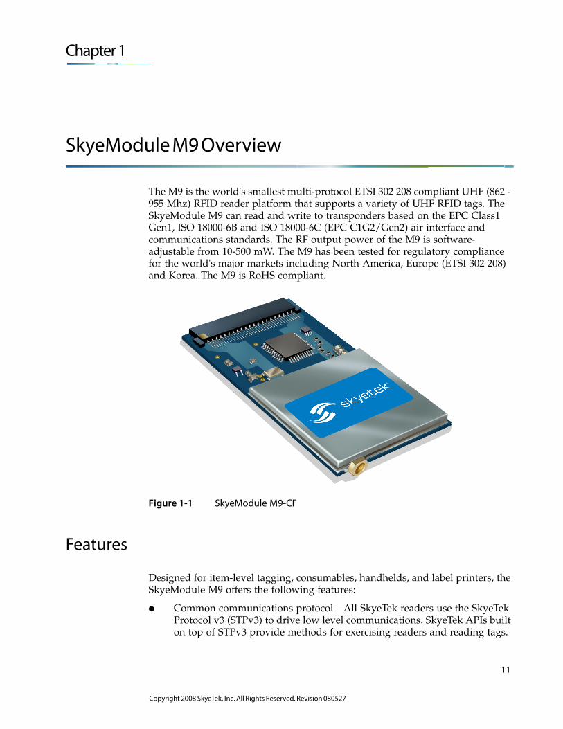
The M9 is the world's smallest multi-protocol ETSI 302 208 compliant UHF (862 - 955 Mhz) RFID reader platform that supports a variety of UHF RFID tags. The SkyeModule M9 can read and write to transponders based on the EPC Class1 Gen1, ISO 18000-6B and ISO 18000-6C (EPC C1G2/Gen2) air interface and communications standards. The RF output power of the M9 is software-adjustable from 10-500 mW. The M9 has been tested for regulatory compliance for the world's major markets including North America, Europe (ETSI 302 208) and Korea. The M9 is RoHS compliant.
Figure 1-1 SkyeModule M9-CF
Features
Designed for item-level tagging, consumables, handhelds, and label printers, the SkyeModule M9 offers the following features:
● Common communications protocol—All SkyeTek readers use the SkyeTek Protocol v3 (STPv3) to drive low level communications. SkyeTek APIs built on top of STPv3 provide methods for exercising readers and reading tags.
11
Copyright 2008 SkyeTek, Inc. All Rights Reserved. Revision 080527
SkyeWare™ Software
● Multiple communications interfaces: TTL Serial, SPI, I2C, and native USB for connection to a host PC with or without a serial port. These options are software-selectable to support both loosely and tightly coupled integrations. The SkyeModule M9 also has seven programmable GPIO pins for I/O connections to peripherals.
● The SkyeModule M9 is optimized to support a communication rate of 40/80 kbps. A standard 50 Ω antenna output enables use of an external antenna to optimize the read range/rate.
● Serial data rates are adjustable from 9.6 to 115.2 kbps. Field-upgradable firmware provides forward compatibility for adding future tag protocols, security features, and customized enhancements.
SkyeWare™ Software
All SkyeModule M9 developer kits ship with the SkyeWare 4 software package for Microsoft® Windows® to aid your RFID development process. This package includes
● Setup Wizard— This Wizard guides you through the setup, configuration, and testing of your new SkyeModule reader. It takes you through all the steps necessary for connecting your hardware, running diagnostic tests, and optimizing your reader configuration. It concludes with useful links to additional SkyeTek software and documentation.
● Demonstration functions– This utility offers a quick way to perform high-level demonstrations of the basic functionality of the SkyeModule M9. You can test read range, anti-collision (singulation) capabilities, and use inventory selection and memory functions.
● Configuration – You can easily view and change reader configuration parameters, adjust radio settings, configure tags, and update or change firmware.
● Test Software – The test utility provides a GUI interface for constructing the SkyeTek Protocol v3 commands in either ASCII or binary format, based on tag type and selected flags. You can build and test low-level SkyeTek protocol commands and use all the features of the reader at the protocol level. It is an excellent way to learn more about SkyeTek Protocol v3 commands. For more information, see the SkyeTek Development Kit User Guide.
● APIs – SkyeTek offers C and .NET APIs so that you can easily create interfaces between your programming language and any SkyeTek reader modules that communicate using SkyeTek Protocol v3. The APIs provide a rich assortment of functions that allows complete access to and manipulation of your SkyeModule M9. Refer to the SkyeTek C and .NET API Reference Guide, installed in the Documentation folder installed with SkyeWare.
12 SkyeModuleTM M9 Reference Guide
Copyright 2008 SkyeTek, Inc. All Rights Reserved. Revision 080527
Chapter 2
Mechanical Specifications
The SkyeModule M9 has Mounting Hole (MH) and CompactFlash (CF) variants.
● See Appendix C, on page C-119 for specifications for previous versions of the M9.
Mounting Hole Variant
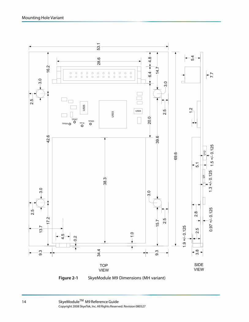
Figure 2-1 on page 2-14 shows the dimensions of the MH variant.
Outside dimensions: 53.0 mm x 70.0 mm = 3710 mm2
Height: 7.7 mm
Mounting holes: 3.0 mm diameter 45.0 mm center-to-center (width) 40.0 mm center-to-center (length)
Clearance:Approx. 2.5 mm between edge of mounting hole and edge of printed circuit board (PCB) (width/side-to-side direction)
Approx. 13.2 mm between edge of mounting hole and front of PCB (main connector side)
Approx. 14.0 mm between the edge of mounting hole and back of PCB (antenna connector side)
Weight17.0 grams
L o r e m ip s u m d o lo r s it a me t, c o n s e c te tu e rlo b o r tis p u lv in a r ma g n a . Mo r b i q u is
fe r m e n tu m. In s o d a le s fe u g ia t s e m. S e d u t p e d e . N a m te mp u s . Ma e c e n a s r u tr u mC u r a b itu r n u n c . A e n e a n s c e le r is q u e
S u s p e n d is s e e r a t. Ma u r is u t c uv e s tib u lu m s e m. V iv a mu s e t, v e l le c tu s v ita e
U t o r c i r is u s , c o n v a llis e t, S u s p e n d is s e s u s c ip it v u lp u ta te e lit.
e tr a e n im. S u s p e n d is s e e le me n tu m. S e d e n im lo r e m, s u s c ip it q u is , v e s tib u lu m
in , s u s c ip it n o n , a n te . L o r e m ip s u m d o lo r s it a me t, c o n s e c te tu e r
h a b ita s s e p la te a d ic tu ms t.
S u s p e n d is s e s u s c ip it v u lp u ta te e lit.
. S e d
c o n s e c te tu e r r is u s .
lu c tu s imp e r d ie t.
p r e tiu m c o n d ime n tu m.
Note – All drawing dimensions are in millimeters. Production units may vary slightly from the measurements given.
13
Copyright 2008 SkyeTek, Inc. All Rights Reserved. Revision 080527
Mounting Hole Variant
U5
03 U504
TP505TP10
TP507
TP504
U12
U1
34.4
69.6
1.0
38.3
6.4
13.7
4.5
5.1
2.5
1.9
+/-
0.1
25
0.9
7 +
/-0
.12
51.5
+/-
0.1
25
5.4
1.2
0.2
4.8
1.3
+/-
0.1
25
3.0
15.7
39.6
3.0
20.0
14.7
28
.6
9.3
9.3
3.0
2.5
2.5
3.0
2.5
2.5
TOP
VIEW
SIDE
VIEW
U5
05
7.7
3.8
53.1
2.8
17.2
42.6
16.2
test spacer text spacer text spacer text spacer text spacer text spacer text spacer text spacer text spacer text spacer text spacer
text
Figure 2-1 SkyeModule M9 Dimensions (MH variant)
14 SkyeModuleTM M9 Reference Guide
Copyright 2008 SkyeTek, Inc. All Rights Reserved. Revision 080527
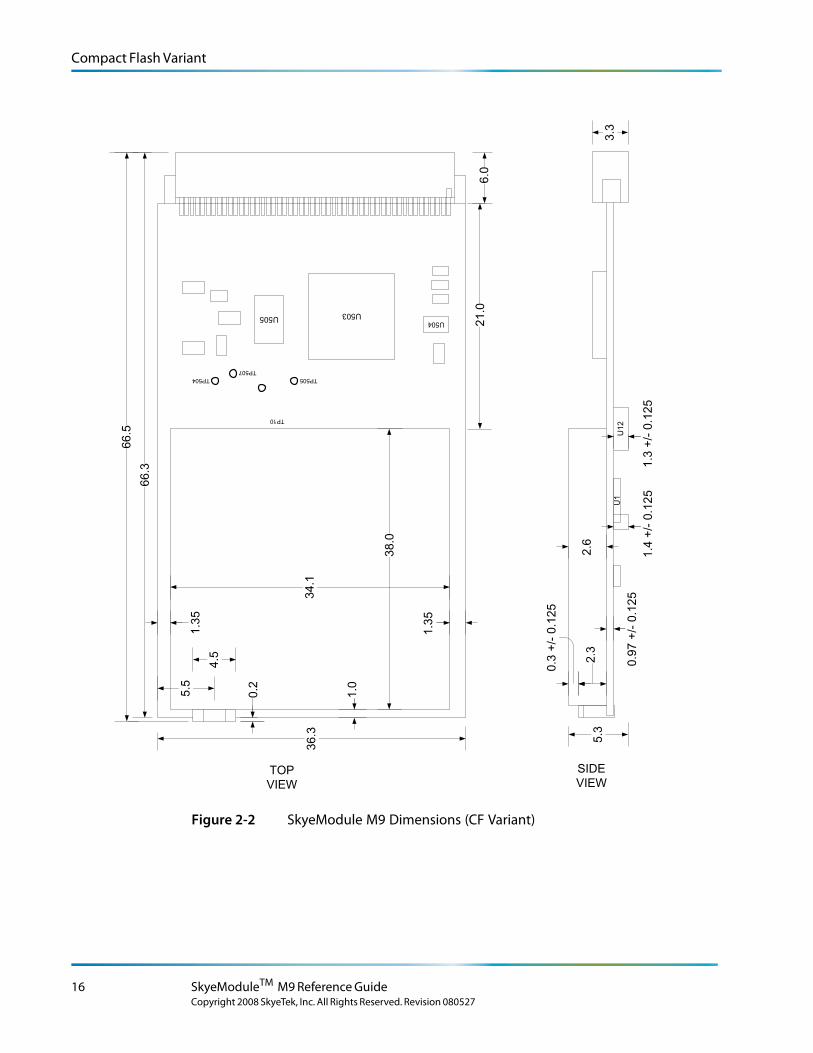
Compact Flash Variant
Compact Flash Variant
Figure 2-2 on page 2-16 shows the dimensions of the compact flash (CF) variant.
Dimensions: 66.1 mm x 32.5 mm = 2148.25 mm2
Height: 6.35 mm
Weight14.2 grams
L o r e m ip s u m d o lo r s it a me t, c o n s e c te tu e rlo b o r tis p u lv in a r ma g n a . Mo r b i q u is
fe r m e n tu m. In s o d a le s fe u g ia t s e m. S e d u t p e d e . N a m te mp u s . Ma e c e n a s r u tr u mC u r a b itu r n u n c . A e n e a n s c e le r is q u e
S u s p e n d is s e e r a t. Ma u r is u t c uv e s tib u lu m s e m. V iv a mu s e t, v e l le c tu s v ita e
U t o r c i r is u s , c o n v a llis e t, S u s p e n d is s e s u s c ip it v u lp u ta te e lit.
e tr a e n im. S u s p e n d is s e e le me n tu m. S e d e n im lo r e m, s u s c ip it q u is , v e s tib u lu m
in , s u s c ip it n o n , a n te . L o r e m ip s u m d o lo r s it a me t, c o n s e c te tu e r
h a b ita s s e p la te a d ic tu ms t.
S u s p e n d is s e s u s c ip it v u lp u ta te e lit.
. S e d
c o n s e c te tu e r r is u s .
lu c tu s imp e r d ie t.
p r e tiu m c o n d ime n tu m.
Note – All drawing dimensions are in millimeters. Production units may vary slightly from the measurements given.
Connector Specifications
Table 2-1SkyeModule M9 Connector Specifications
SkyeModule Type
Connector Type Manufacturer Manufacturer’s Part Number
M9-CF Compact flash type II (receptacle on module)
Molex 67799-0011
CF counterpart to connect to module
Molex 67155-0002
M9-MH Surface-mount protected header (receptacle on module)
Hirose DF11Z-24DP-2V
MH counterpart to connect to module
Hirose DF11Z-24DS-2V
Mechanical Specifications 15Copyright 2008 SkyeTek, Inc. All Rights Reserved. Revision 080527
Compact Flash Variant
TP10
U1
2U
1
36.3
66.3
1.0
38.0
6.0
5.5
4.5
34.1
5.3
2.3
0.3
+/-
0.1
25
0.9
7 +
/-0.1
25
1.3
+/-
0.1
25
3.3
1.3
5
1.3
5
0.2
66.5
21
.0
2.6
U503U505U504
TP505
TP507
TP504
1.4
+/-
0.1
25
TOP
VIEW
SIDE
VIEW
Figure 2-2 SkyeModule M9 Dimensions (CF Variant)
16 SkyeModuleTM M9 Reference Guide
Copyright 2008 SkyeTek, Inc. All Rights Reserved. Revision 080527
Chapter 3
Environmental Specifications
L o r e m ip s u m d o lo r s it a me t, c o n s e c te tu e rlo b o r tis p u lv in a r ma g n a . Mo r b i q u is
fe r m e n tu m. In s o d a le s fe u g ia t s e m. S e d u t p e d e . N a m te mp u s . Ma e c e n a s r u tr u mC u r a b itu r n u n c . A e n e a n s c e le r is q u e
S u s p e n d is s e e r a t. Ma u r is u t c uv e s tib u lu m s e m. V iv a mu s e t, v e l le c tu s v ita e
U t o r c i r is u s , c o n v a llis e t, S u s p e n d is s e s u s c ip it v u lp u ta te e lit.
e tr a e n im. S u s p e n d is s e e le me n tu m. S e d e n im lo r e m, s u s c ip it q u is , v e s tib u lu m
in , s u s c ip it n o n , a n te . L o r e m ip s u m d o lo r s it a me t, c o n s e c te tu e r
h a b ita s s e p la te a d ic tu ms t.
S u s p e n d is s e s u s c ip it v u lp u ta te e lit.
. S e d
c o n s e c te tu e r r is u s .
lu c tu s imp e r d ie t.
p r e tiu m c o n d ime n tu m.
Note – See Appendix C, on page C-119 for specifications for previous versions of the M9.
Electrostatic PrecautionsCAUTION – Failure to take proper electrostatic precautions may result in damage to or failure of your SkyeModule M9.
The SkyeModule M9 contains static-sensitive parts. Observe the following precautions to prevent damage to these parts.
● Wear a static grounding strap when handling electronic control components.
● Keep all plastic, vinyl, and styrofoam (except antistatic versions) away from printed circuit boards.
● Do not touch the components or conductors on a printed circuit board with your hands or with conductive devices.
17
Copyright 2008 SkyeTek, Inc. All Rights Reserved. Revision 080527
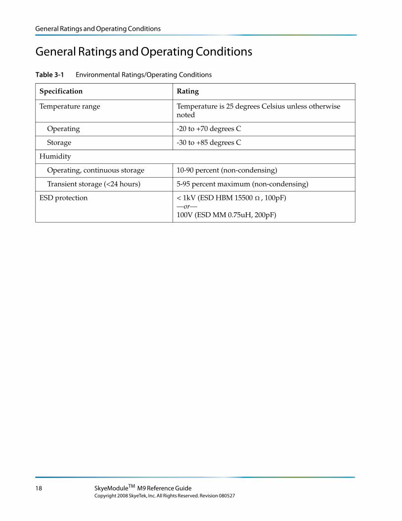
General Ratings and Operating Conditions
General Ratings and Operating Conditions
Table 3-1 Environmental Ratings/Operating Conditions
Specification Rating
Temperature range Temperature is 25 degrees Celsius unless otherwise noted
Operating -20 to +70 degrees C
Storage -30 to +85 degrees C
Humidity
Operating, continuous storage 10-90 percent (non-condensing)
Transient storage (<24 hours) 5-95 percent maximum (non-condensing)
ESD protection < 1kV (ESD HBM 15500 Ω , 100pF) —or— 100V (ESD MM 0.75uH, 200pF)
18 SkyeModuleTM M9 Reference Guide
Copyright 2008 SkyeTek, Inc. All Rights Reserved. Revision 080527
Chapter 4
Electrical Specifications
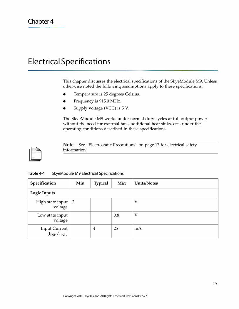
This chapter discusses the electrical specifications of the SkyeModule M9. Unless otherwise noted the following assumptions apply to these specifications:
● Temperature is 25 degrees Celsius.
● Frequency is 915.0 MHz.
● Supply voltage (VCC) is 5 V.
The SkyeModule M9 works under normal duty cycles at full output power without the need for external fans, additional heat sinks, etc., under the operating conditions described in these specifications.
L o r e m ip s u m d o lo r s it a me t, c o n s e c te tu e rlo b o r tis p u lv in a r ma g n a . Mo r b i q u is
fe r m e n tu m. In s o d a le s fe u g ia t s e m. S e d u t p e d e . N a m te mp u s . Ma e c e n a s r u tr u mC u r a b itu r n u n c . A e n e a n s c e le r is q u e
S u s p e n d is s e e r a t. Ma u r is u t c uv e s tib u lu m s e m. V iv a mu s e t, v e l le c tu s v ita e
U t o r c i r is u s , c o n v a llis e t, S u s p e n d is s e s u s c ip it v u lp u ta te e lit.
e tr a e n im. S u s p e n d is s e e le me n tu m. S e d e n im lo r e m, s u s c ip it q u is , v e s tib u lu m
in , s u s c ip it n o n , a n te . L o r e m ip s u m d o lo r s it a me t, c o n s e c te tu e r
h a b ita s s e p la te a d ic tu ms t.
S u s p e n d is s e s u s c ip it v u lp u ta te e lit.
. S e d
c o n s e c te tu e r r is u s .
lu c tu s imp e r d ie t.
p r e tiu m c o n d ime n tu m.
Note – See ‘‘Electrostatic Precautions’’ on page 17 for electrical safety information.
Table 4-1 SkyeModule M9 Electrical Specifications
Specification Min Typical Max Units/Notes
Logic Inputs
High state input voltage
2 V
Low state input voltage
0.8 V
Input Current (IINH/IINL)
4 25 mA
19
Copyright 2008 SkyeTek, Inc. All Rights Reserved. Revision 080527
Absolute Maximum Ratings
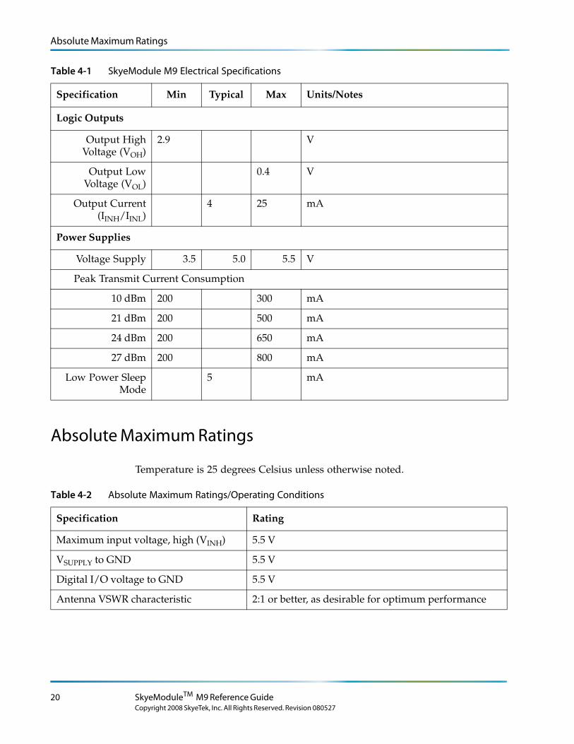
Absolute Maximum Ratings
Temperature is 25 degrees Celsius unless otherwise noted.
Table 4-2 Absolute Maximum Ratings/Operating Conditions
Specification Rating
Maximum input voltage, high (VINH) 5.5 V
VSUPPLY to GND 5.5 V
Digital I/O voltage to GND 5.5 V
Antenna VSWR characteristic 2:1 or better, as desirable for optimum performance
Logic Outputs
Output High Voltage (VOH)
2.9 V
Output Low Voltage (VOL)
0.4 V
Output Current (IINH/IINL)
4 25 mA
Power Supplies
Voltage Supply 3.5 5.0 5.5 V
Peak Transmit Current Consumption
10 dBm 200 300 mA
21 dBm 200 500 mA
24 dBm 200 650 mA
27 dBm 200 800 mA
Low Power Sleep Mode
5 mA
Table 4-1 SkyeModule M9 Electrical Specifications
Specification Min Typical Max Units/Notes
20 SkyeModuleTM M9 Reference Guide
Copyright 2008 SkyeTek, Inc. All Rights Reserved. Revision 080527
Chapter 5
Host Interface Specification
The following sections describe the power and host communication connections for the SkyeModule M9.
Host to Reader Interfaces
The SkyeModule M9 supports the following microcontroller host interfaces for easy integration into existing systems:
● TTL (RS-232 can be supported with additional circuitry)
● SPI
● I2C
● USB
The SkyeModule M9, when used with a host interface board, supports RS-232 and USB communications. The host interface board provides a USB connector and a TTL-to-RS-232-level converter for the TTL host interface. Each interface is software-selectable and only one host interface is active at a time. The host interface is selected based on the power-up default value and can be changed at run time using the Host Interface Type system parameter. The SkyeModule M9 operates under host control using SkyeTek Protocol v3 sent over one of the host interfaces described in this chapter.
L o r e m ip s u m d o lo r s it a me t, c o n s e c te tu e rlo b o r tis p u lv in a r ma g n a . Mo r b i q u is
fe r m e n tu m. In s o d a le s fe u g ia t s e m. S e d u t p e d e . N a m te mp u s . Ma e c e n a s r u tr u mC u r a b itu r n u n c . A e n e a n s c e le r is q u e
S u s p e n d is s e e r a t. Ma u r is u t c uv e s tib u lu m s e m. V iv a mu s e t, v e l le c tu s v ita e
U t o r c i r is u s , c o n v a llis e t, S u s p e n d is s e s u s c ip it v u lp u ta te e lit.
e tr a e n im. S u s p e n d is s e e le me n tu m. S e d e n im lo r e m, s u s c ip it q u is , v e s tib u lu m
in , s u s c ip it n o n , a n te . L o r e m ip s u m d o lo r s it a me t, c o n s e c te tu e r
h a b ita s s e p la te a d ic tu ms t.
S u s p e n d is s e s u s c ip it v u lp u ta te e lit.
. S e d
c o n s e c te tu e r r is u s .
lu c tu s imp e r d ie t.
p r e tiu m c o n d ime n tu m.
Note – SkyeModule M9s shipped with the SkyeTek Development Kit are preset to use USB communications and a power level of 20 dBm.
21
Copyright 2008 SkyeTek, Inc. All Rights Reserved. Revision 080527
Host Interface Specification
TTL
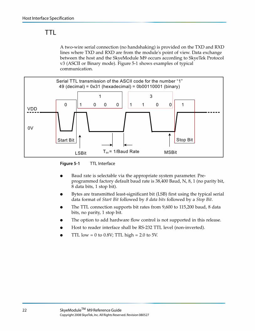
A two-wire serial connection (no handshaking) is provided on the TXD and RXD lines where TXD and RXD are from the module's point of view. Data exchange between the host and the SkyeModule M9 occurs according to SkyeTek Protocol v3 (ASCII or Binary mode). Figure 5-1 shows examples of typical communication.
Serial TTL transmission of the ASCII code for the number “1”49 (decimal) = 0x31 (hexadecimal) = 0b00110001 (binary)
Start Bit
VDD
0V
LSBit MSBit
Stop Bit
Tbit = 1/Baud Rate
0000 01 1 11 0
1 3
Figure 5-1 TTL Interface
● Baud rate is selectable via the appropriate system parameter. Pre-programmed factory default baud rate is 38,400 Baud, N, 8, 1 (no parity bit, 8 data bits, 1 stop bit).
● Bytes are transmitted least-significant bit (LSB) first using the typical serial data format of Start Bit followed by 8 data bits followed by a Stop Bit.
● The TTL connection supports bit rates from 9,600 to 115,200 baud, 8 data bits, no parity, 1 stop bit.
● The option to add hardware flow control is not supported in this release.
● Host to reader interface shall be RS-232 TTL level (non-inverted).
● TTL low = 0 to 0.8V; TTL high = 2.0 to 5V.
22 SkyeModuleTM M9 Reference Guide
Copyright 2008 SkyeTek, Inc. All Rights Reserved. Revision 080527
Host Interface Specification
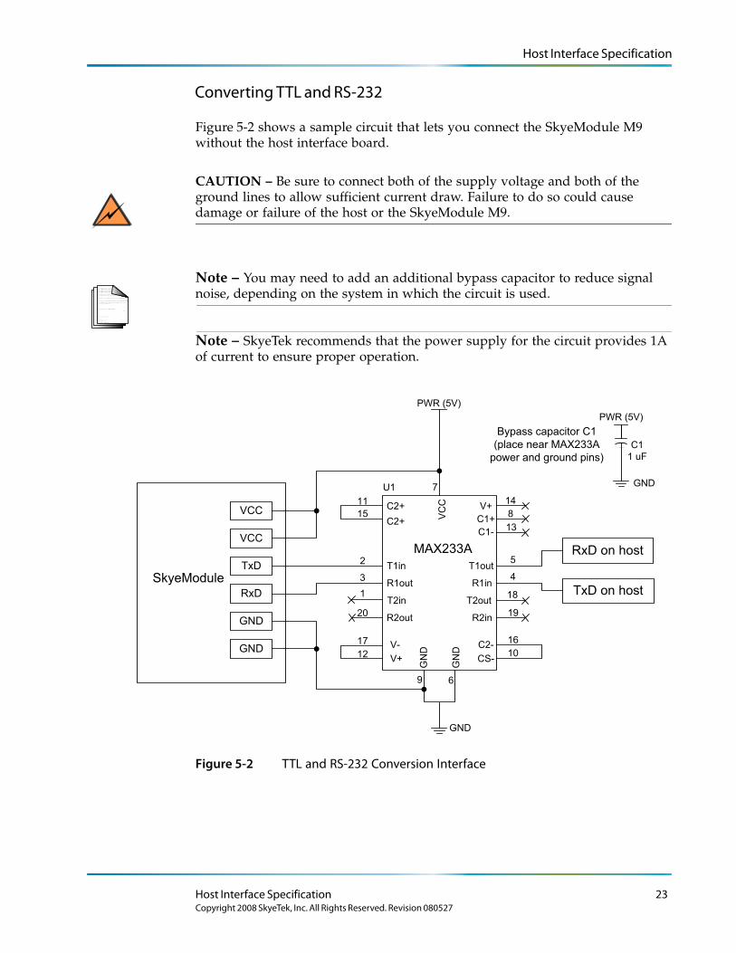
Converting TTL and RS-232
Figure 5-2 shows a sample circuit that lets you connect the SkyeModule M9 without the host interface board.
CAUTION – Be sure to connect both of the supply voltage and both of the ground lines to allow sufficient current draw. Failure to do so could cause damage or failure of the host or the SkyeModule M9.
L o r e m ip s u m d o lo r s it a me t, c o n s e c te tu e rlo b o r tis p u lv in a r ma g n a . Mo r b i q u is
fe r m e n tu m. In s o d a le s fe u g ia t s e m. S e d u t p e d e . N a m te mp u s . Ma e c e n a s r u tr u mC u r a b itu r n u n c . A e n e a n s c e le r is q u e
S u s p e n d is s e e r a t. Ma u r is u t c uv e s tib u lu m s e m. V iv a mu s e t, v e l le c tu s v ita e
U t o r c i r is u s , c o n v a llis e t, S u s p e n d is s e s u s c ip it v u lp u ta te e lit.
e tr a e n im. S u s p e n d is s e e le me n tu m. S e d e n im lo r e m, s u s c ip it q u is , v e s tib u lu m
in , s u s c ip it n o n , a n te . L o r e m ip s u m d o lo r s it a me t, c o n s e c te tu e r
h a b ita s s e p la te a d ic tu ms t.
S u s p e n d is s e s u s c ip it v u lp u ta te e lit.
. S e d
c o n s e c te tu e r r is u s .
lu c tu s imp e r d ie t.
p r e tiu m c o n d ime n tu m.
SkyeModule
RxD on host
TxD on host
VCC
GND
GND
RxD
TxD
VCC
VC
CC2+
GN
D
GN
D
C2+
V-
V+
V+
C1+
C2-
CS-
C1-
MAX233A
R2out R2in
T2in T2out
R1out R1in
T1in T1out
11
15
20
1
17
12
9 6
U1 7
2
3
14
8
19
18
16
10
5
4
13
GND
PWR (5V)
Bypass capacitor C1
(place near MAX233A
power and ground pins)
PWR (5V)
GND
C1
1 uF
Note – You may need to add an additional bypass capacitor to reduce signal noise, depending on the system in which the circuit is used.
Note – SkyeTek recommends that the power supply for the circuit provides 1A of current to ensure proper operation.
Figure 5-2 TTL and RS-232 Conversion Interface
Host Interface Specification 23Copyright 2008 SkyeTek, Inc. All Rights Reserved. Revision 080527
Host Interface Specification
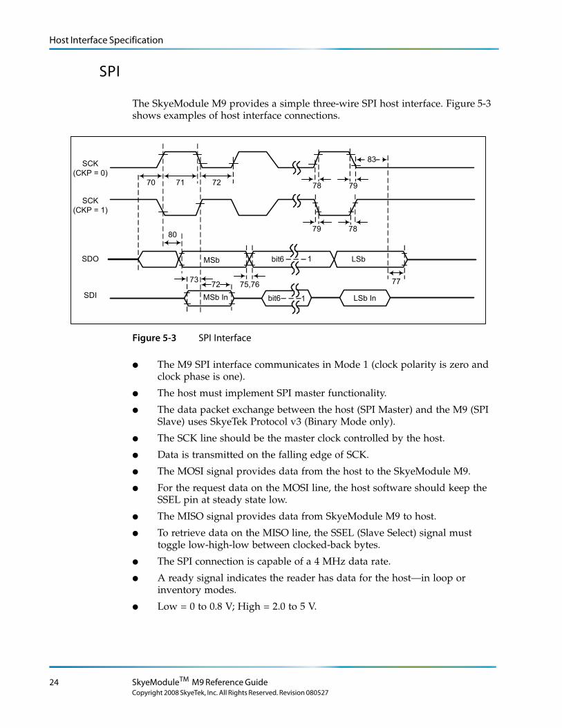
SPI
The SkyeModule M9 provides a simple three-wire SPI host interface. Figure 5-3 shows examples of host interface connections.
SCK(CKP = 0)
SCK(CKP = 1)
SDO
SDI
80
73 75,76 77
78
7879
79
MSb
MSb In LSb In
LSbbit6
bit6 1
1
83
72
70 7271
Figure 5-3 SPI Interface
● The M9 SPI interface communicates in Mode 1 (clock polarity is zero and clock phase is one).
● The host must implement SPI master functionality.
● The data packet exchange between the host (SPI Master) and the M9 (SPI Slave) uses SkyeTek Protocol v3 (Binary Mode only).
● The SCK line should be the master clock controlled by the host.
● Data is transmitted on the falling edge of SCK.
● The MOSI signal provides data from the host to the SkyeModule M9.
● For the request data on the MOSI line, the host software should keep the SSEL pin at steady state low.
● The MISO signal provides data from SkyeModule M9 to host.
● To retrieve data on the MISO line, the SSEL (Slave Select) signal must toggle low-high-low between clocked-back bytes.
● The SPI connection is capable of a 4 MHz data rate.
● A ready signal indicates the reader has data for the host—in loop or inventory modes.
● Low = 0 to 0.8 V; High = 2.0 to 5 V.
24 SkyeModuleTM M9 Reference Guide
Copyright 2008 SkyeTek, Inc. All Rights Reserved. Revision 080527
Host Interface Specification
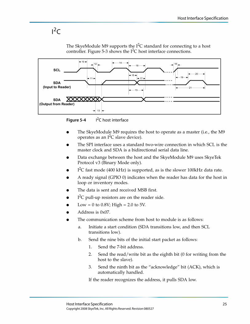
I2C
The SkyeModule M9 supports the I2C standard for connecting to a host controller. Figure 5-3 shows the I2C host interface connections.
10
11
12
13
14
13
1517
1618
1920
SCL
SDA(Input to Reader)
SDA(Output from Reader)
21
Figure 5-4 I2C host interface
● The SkyeModule M9 requires the host to operate as a master (i.e., the M9 operates as an I2C slave device).
● The SPI interface uses a standard two-wire connection in which SCL is the master clock and SDA is a bidirectional serial data line.
● Data exchange between the host and the SkyeModule M9 uses SkyeTek Protocol v3 (Binary Mode only).
● I2C fast mode (400 kHz) is supported, as is the slower 100kHz data rate.
● A ready signal (GPIO 0) indicates when the reader has data for the host in loop or inventory modes.
● The data is sent and received MSB first.
● I2C pull-up resistors are on the reader side.
● Low = 0 to 0.8V; High = 2.0 to 5V.
● Address is 0x07.
● The communication scheme from host to module is as follows:
a. Initiate a start condition (SDA transitions low, and then SCL transitions low).
b. Send the nine bits of the initial start packet as follows:
1. Send the 7-bit address.
2. Send the read/write bit as the eighth bit (0 for writing from the host to the slave).
3. Send the ninth bit as the “acknowledge” bit (ACK), which is automatically handled.
If the reader recognizes the address, it pulls SDA low.
Host Interface Specification 25Copyright 2008 SkyeTek, Inc. All Rights Reserved. Revision 080527
Host Interface Specification
c. Use the bus to clock each byte of the Skyetek protocol request.
d. After sending the request, initiate a stop condition. (SCL transitions high, and then SDA transitions high.)
L o r e m ip s u m d o lo r s it a me t, c o n s e c te tu e rlo b o r tis p u lv in a r ma g n a . Mo r b i q u is
fe r m e n tu m. In s o d a le s fe u g ia t s e m. S e d u t p e d e . N a m te mp u s . Ma e c e n a s r u tr u mC u r a b itu r n u n c . A e n e a n s c e le r is q u e
S u s p e n d is s e e r a t. Ma u r is u t c uv e s tib u lu m s e m. V iv a mu s e t, v e l le c tu s v ita e
U t o r c i r is u s , c o n v a llis e t, S u s p e n d is s e s u s c ip it v u lp u ta te e lit.
e tr a e n im. S u s p e n d is s e e le me n tu m. S e d e n im lo r e m, s u s c ip it q u is , v e s tib u lu m
in , s u s c ip it n o n , a n te . L o r e m ip s u m d o lo r s it a me t, c o n s e c te tu e r
h a b ita s s e p la te a d ic tu ms t.
S u s p e n d is s e s u s c ip it v u lp u ta te e lit.
. S e d
c o n s e c te tu e r r is u s .
lu c tu s imp e r d ie t.
p r e tiu m c o n d ime n tu m.
Note – You may need to include from one to a few hundred milliseconds of delay. The delay may vary for tag-specific commands.
● Communication scheme from module to host is as follows:
a. Initiate a start condition. (SDA transitions low, and then SCL transitions low.)
b. Send the 7-bit address.
c. Send the read/write bit as the eighth bit (1 for reading from the slave to the host).
If the reader recognizes the address, it pulls SDA low for the ACK bit.
d. Clock each byte of the Skyetek protocol response from the module.
e. After receiving the response, is received, initiate a stop condition. (SCL transitions high, and then SDA transitions high.)
26 SkyeModuleTM M9 Reference Guide
Copyright 2008 SkyeTek, Inc. All Rights Reserved. Revision 080527
Host Interface Specification
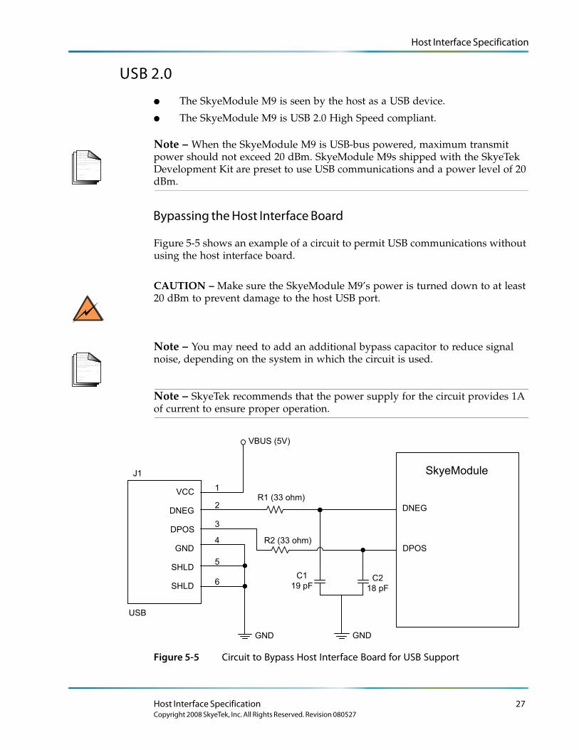
USB 2.0
● The SkyeModule M9 is seen by the host as a USB device.
● The SkyeModule M9 is USB 2.0 High Speed compliant.
L o r e m ip s u m d o lo r s it a me t, c o n s e c te tu e rlo b o r tis p u lv in a r ma g n a . Mo r b i q u is
fe r m e n tu m. In s o d a le s fe u g ia t s e m. S e d u t p e d e . N a m te mp u s . Ma e c e n a s r u tr u mC u r a b itu r n u n c . A e n e a n s c e le r is q u e
S u s p e n d is s e e r a t. Ma u r is u t c uv e s tib u lu m s e m. V iv a mu s e t, v e l le c tu s v ita e
U t o r c i r is u s , c o n v a llis e t, S u s p e n d is s e s u s c ip it v u lp u ta te e lit.
e tr a e n im. S u s p e n d is s e e le me n tu m. S e d e n im lo r e m, s u s c ip it q u is , v e s tib u lu m
in , s u s c ip it n o n , a n te . L o r e m ip s u m d o lo r s it a me t, c o n s e c te tu e r
h a b ita s s e p la te a d ic tu ms t.
S u s p e n d is s e s u s c ip it v u lp u ta te e lit.
. S e d
c o n s e c te tu e r r is u s .
lu c tu s imp e r d ie t.
p r e tiu m c o n d ime n tu m.
Note – When the SkyeModule M9 is USB-bus powered, maximum transmit power should not exceed 20 dBm. SkyeModule M9s shipped with the SkyeTek Development Kit are preset to use USB communications and a power level of 20 dBm.
Bypassing the Host Interface Board
Figure 5-5 shows an example of a circuit to permit USB communications without using the host interface board.
CAUTION – Make sure the SkyeModule M9’s power is turned down to at least 20 dBm to prevent damage to the host USB port.
L o r e m ip s u m d o lo r s it a me t, c o n s e c te tu e rlo b o r tis p u lv in a r ma g n a . Mo r b i q u is
fe r m e n tu m. In s o d a le s fe u g ia t s e m. S e d u t p e d e . N a m te mp u s . Ma e c e n a s r u tr u mC u r a b itu r n u n c . A e n e a n s c e le r is q u e
S u s p e n d is s e e r a t. Ma u r is u t c uv e s tib u lu m s e m. V iv a mu s e t, v e l le c tu s v ita e
U t o r c i r is u s , c o n v a llis e t, S u s p e n d is s e s u s c ip it v u lp u ta te e lit.
e tr a e n im. S u s p e n d is s e e le me n tu m. S e d e n im lo r e m, s u s c ip it q u is , v e s tib u lu m
in , s u s c ip it n o n , a n te . L o r e m ip s u m d o lo r s it a me t, c o n s e c te tu e r
h a b ita s s e p la te a d ic tu ms t.
S u s p e n d is s e s u s c ip it v u lp u ta te e lit.
. S e d
c o n s e c te tu e r r is u s .
lu c tu s imp e r d ie t.
p r e tiu m c o n d ime n tu m.
Note – You may need to add an additional bypass capacitor to reduce signal noise, depending on the system in which the circuit is used.
Note – SkyeTek recommends that the power supply for the circuit provides 1A of current to ensure proper operation.
SkyeModule
VCC
GND
SHLD
SHLD
DPOS
DNEG
1
5
4
6
2
3
GND
J1
USB
VBUS (5V)
R1 (33 ohm)
R2 (33 ohm)
GND
C1
19 pFC2
18 pF
DNEG
DPOS
Figure 5-5 Circuit to Bypass Host Interface Board for USB Support
Host Interface Specification 27Copyright 2008 SkyeTek, Inc. All Rights Reserved. Revision 080527
Host Interface Specification
Connecting to the M9
Pin Mapping of the SkyeModule M9-MH Variant
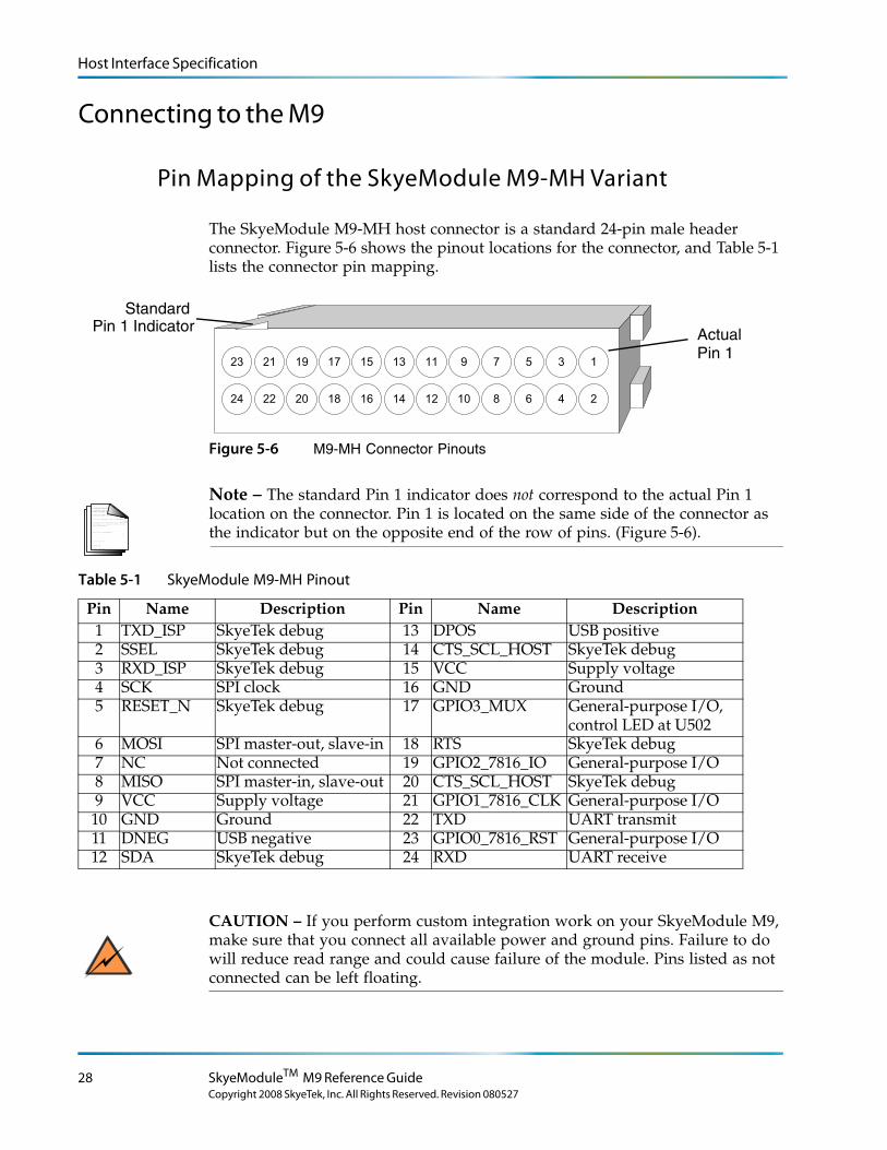
The SkyeModule M9-MH host connector is a standard 24-pin male header connector. Figure 5-6 shows the pinout locations for the connector, and Table 5-1 lists the connector pin mapping.
23
24
11
12
13
14
9
10
7
8
5
6
3
4
1
2
15
16
17
18
19
20
21
22
Standard
Actual Pin 1 Indicator
Pin 1
Figure 5-6 M9-MH Connector Pinouts
L o r e m ip s u m d o lo r s it a me t, c o n s e c te tu e rlo b o r tis p u lv in a r ma g n a . Mo r b i q u is
fe r m e n tu m. In s o d a le s fe u g ia t s e m. S e d u t p e d e . N a m te mp u s . Ma e c e n a s r u tr u mC u r a b itu r n u n c . A e n e a n s c e le r is q u e
S u s p e n d is s e e r a t. Ma u r is u t c uv e s tib u lu m s e m. V iv a mu s e t, v e l le c tu s v ita e
U t o r c i r is u s , c o n v a llis e t, S u s p e n d is s e s u s c ip it v u lp u ta te e lit.
e tr a e n im. S u s p e n d is s e e le me n tu m. S e d e n im lo r e m, s u s c ip it q u is , v e s tib u lu m
in , s u s c ip it n o n , a n te . L o r e m ip s u m d o lo r s it a me t, c o n s e c te tu e r
h a b ita s s e p la te a d ic tu ms t.
S u s p e n d is s e s u s c ip it v u lp u ta te e lit.
. S e d
c o n s e c te tu e r r is u s .
lu c tu s imp e r d ie t.
p r e tiu m c o n d ime n tu m.
Note – The standard Pin 1 indicator does not correspond to the actual Pin 1 location on the connector. Pin 1 is located on the same side of the connector as the indicator but on the opposite end of the row of pins. (Figure 5-6).
Table 5-1 SkyeModule M9-MH Pinout
Pin Name Description Pin Name Description1 TXD_ISP SkyeTek debug 13 DPOS USB positive2 SSEL SkyeTek debug 14 CTS_SCL_HOST SkyeTek debug3 RXD_ISP SkyeTek debug 15 VCC Supply voltage4 SCK SPI clock 16 GND Ground5 RESET_N SkyeTek debug 17 GPIO3_MUX General-purpose I/O,
control LED at U5026 MOSI SPI master-out, slave-in 18 RTS SkyeTek debug7 NC Not connected 19 GPIO2_7816_IO General-purpose I/O8 MISO SPI master-in, slave-out 20 CTS_SCL_HOST SkyeTek debug9 VCC Supply voltage 21 GPIO1_7816_CLK General-purpose I/O
10 GND Ground 22 TXD UART transmit11 DNEG USB negative 23 GPIO0_7816_RST General-purpose I/O12 SDA SkyeTek debug 24 RXD UART receive
CAUTION – If you perform custom integration work on your SkyeModule M9, make sure that you connect all available power and ground pins. Failure to do will reduce read range and could cause failure of the module. Pins listed as not connected can be left floating.
28 SkyeModuleTM M9 Reference Guide
Copyright 2008 SkyeTek, Inc. All Rights Reserved. Revision 080527
Host Interface Specification
Pin Mapping of the SkyeModule M9-CF Variant
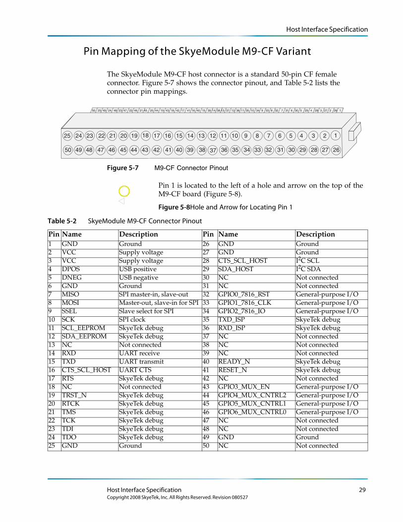
The SkyeModule M9-CF host connector is a standard 50-pin CF female connector. Figure 5-7 shows the connector pinout, and Table 5-2 lists the connector pin mappings.
24 357 689 272829303111 1012 34 323336 353713 26 12350 49 2045 19 1847 22 46 43 42 1617 1521 41 40 3944 3814482425
2345678910111213141516171819202122232425
262728293032333435363738394041424344454647484950 31
1
Figure 5-7 M9-CF Connector Pinout
Pin 1 is located to the left of a hole and arrow on the top of the M9-CF board (Figure 5-8).
Figure 5-8Hole and Arrow for Locating Pin 1
Table 5-2 SkyeModule M9-CF Connector Pinout
Pin Name Description Pin Name Description1 GND Ground 26 GND Ground2 VCC Supply voltage 27 GND Ground3 VCC Supply voltage 28 CTS_SCL_HOST I2C SCL4 DPOS USB positive 29 SDA_HOST I2C SDA5 DNEG USB negative 30 NC Not connected 6 GND Ground 31 NC Not connected 7 MISO SPI master-in, slave-out 32 GPIO0_7816_RST General-purpose I/O8 MOSI Master-out, slave-in for SPI 33 GPIO1_7816_CLK General-purpose I/O9 SSEL Slave select for SPI 34 GPIO2_7816_IO General-purpose I/O10 SCK SPI clock 35 TXD_ISP SkyeTek debug11 SCL_EEPROM SkyeTek debug 36 RXD_ISP SkyeTek debug12 SDA_EEPROM SkyeTek debug 37 NC Not connected 13 NC Not connected 38 NC Not connected 14 RXD UART receive 39 NC Not connected 15 TXD UART transmit 40 READY_N SkyeTek debug16 CTS_SCL_HOST UART CTS 41 RESET_N SkyeTek debug17 RTS SkyeTek debug 42 NC Not connected 18 NC Not connected 43 GPIO3_MUX_EN General-purpose I/O19 TRST_N SkyeTek debug 44 GPIO4_MUX_CNTRL2 General-purpose I/O20 RTCK SkyeTek debug 45 GPIO5_MUX_CNTRL1 General-purpose I/O21 TMS SkyeTek debug 46 GPIO6_MUX_CNTRL0 General-purpose I/O22 TCK SkyeTek debug 47 NC Not connected 23 TDI SkyeTek debug 48 NC Not connected 24 TDO SkyeTek debug 49 GND Ground25 GND Ground 50 NC Not connected
Host Interface Specification 29Copyright 2008 SkyeTek, Inc. All Rights Reserved. Revision 080527

Host Interface Specification
CAUTION – If you perform custom integration work on your SkyeModule M9, make sure that you connect all available power and ground pins. Failure to do will reduce read range and could cause failure of the module. Pins listed as not connected can be left floating.
Using the GPIO Pins
You can use the User Port Direction and User Port Value system parameters to address the GPIO pins to set the user port direction (input or output) and the user port value (high or low). For more information, see the following:
● ‘‘User Port Direction’’ on page 60
● ‘‘User Port Value’’ on page 61
L o r e m ip s u m d o lo r s it a me t, c o n s e c te tu e rlo b o r tis p u lv in a r ma g n a . Mo r b i q u is
fe r m e n tu m. In s o d a le s fe u g ia t s e m. S e d u t p e d e . N a m te mp u s . Ma e c e n a s r u tr u mC u r a b itu r n u n c . A e n e a n s c e le r is q u e
S u s p e n d is s e e r a t. Ma u r is u t c uv e s tib u lu m s e m. V iv a mu s e t, v e l le c tu s v ita e
U t o r c i r is u s , c o n v a llis e t, S u s p e n d is s e s u s c ip it v u lp u ta te e lit.
e tr a e n im. S u s p e n d is s e e le me n tu m. S e d e n im lo r e m, s u s c ip it q u is , v e s tib u lu m
in , s u s c ip it n o n , a n te . L o r e m ip s u m d o lo r s it a me t, c o n s e c te tu e r
h a b ita s s e p la te a d ic tu ms t.
S u s p e n d is s e s u s c ip it v u lp u ta te e lit.
. S e d
c o n s e c te tu e r r is u s .
lu c tu s imp e r d ie t.
p r e tiu m c o n d ime n tu m.
Note – GPIO 3 is not available for user I/O; it is connected to the on-board amber LED, which indicates when a successful tag command occurs.
30 SkyeModuleTM M9 Reference Guide
Copyright 2008 SkyeTek, Inc. All Rights Reserved. Revision 080527
Chapter 6
Radio Specifications and Regional Compliance
RF Radio Power
To minimize power consumption for systems that have lower power requirements, the RF transmit power of the SkyeModule M9 is user configurable from 10-27 dBm in steps of 0.1 dB with an accuracy of +/-1 dB across a temperature range of -20 to +70 degrees Celsius. The resolution steps are smaller than the accuracy so that you can fine tune the power level to lower current consumption. See Chapter 10, for information on how to change the RF power level.
Frequency Range
The M9 is a multi-frequency device that operates in the 862-955 MHz range, which span the world's major UHF RFID bands. See “Adjusting System Parameters” below for information on changing operating frequency and region of operation of the M9.
Tag Protocols
The SkyeModule M9 supports the basic tag commands (identify, read, and write) for the following tag protocols:
● EPC C1G1
● EPC C1G2 (ISO18000-6C)
● ISO 18000-6B
L o r e m ip s u m d o lo r s it a me t, c o n s e c te tu e rlo b o r tis p u lv in a r ma g n a . Mo r b i q u is
fe r m e n tu m. In s o d a le s fe u g ia t s e m. S e d u t p e d e . N a m te mp u s . Ma e c e n a s r u tr u mC u r a b itu r n u n c . A e n e a n s c e le r is q u e
S u s p e n d is s e e r a t. Ma u r is u t c uv e s tib u lu m s e m. V iv a mu s e t, v e l le c tu s v ita e
U t o r c i r is u s , c o n v a llis e t, S u s p e n d is s e s u s c ip it v u lp u ta te e lit.
e tr a e n im. S u s p e n d is s e e le me n tu m. S e d e n im lo r e m, s u s c ip it q u is , v e s tib u lu m
in , s u s c ip it n o n , a n te . L o r e m ip s u m d o lo r s it a me t, c o n s e c te tu e r
h a b ita s s e p la te a d ic tu ms t.
S u s p e n d is s e s u s c ip it v u lp u ta te e lit.
. S e d
c o n s e c te tu e r r is u s .
lu c tu s imp e r d ie t.
p r e tiu m c o n d ime n tu m.
Note – For the most current listing of supported tags and features, see the Tag Support list included in the documentation folder installed from your distribution CD or on the SkyeTek Support Portal.
31
Copyright 2008 SkyeTek, Inc. All Rights Reserved. Revision 080527
Recommended Radio Settings for Regional Compliance
Recommended Radio Settings for Regional Compliance
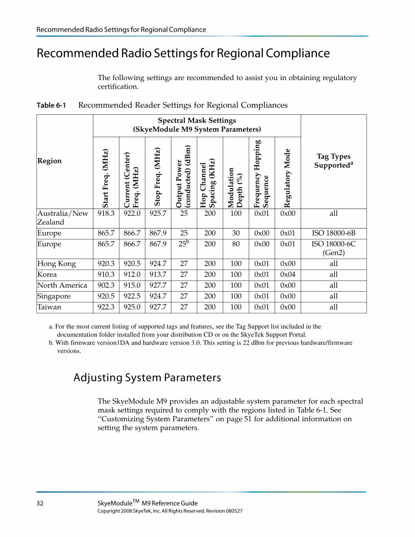
The following settings are recommended to assist you in obtaining regulatory certification.
Table 6-1 Recommended Reader Settings for Regional Compliances
Region
Spectral Mask Settings(SkyeModule M9 System Parameters)
Tag Types Supporteda
Sta
rt F
req
. (M
Hz)
Cu
rren
t (C
ente
r)
Freq
. (M
Hz)
Sto
p F
req
. (M
Hz)
Ou
tpu
t Pow
er
(con
du
cted
) (d
Bm
)
Hop
Ch
ann
el
Sp
acin
g (K
Hz)
Mod
ula
tion
D
epth
(%)
Freq
uen
cy H
opp
ing
S
equ
ence
Reg
ula
tory
Mod
e
Australia/New Zealand
918.3 922.0 925.7 25 200 100 0x01 0x00 all
Europe 865.7 866.7 867.9 25 200 30 0x00 0x01 ISO 18000-6BEurope 865.7 866.7 867.9 25b
b. With firmware version1DA and hardware version 3.0. This setting is 22 dBm for previous hardware/firmware versions.
200 80 0x00 0x01 ISO 18000-6C (Gen2)
Hong Kong 920.3 920.5 924.7 27 200 100 0x01 0x00 allKorea 910.3 912.0 913.7 27 200 100 0x01 0x04 allNorth America 902.3 915.0 927.7 27 200 100 0x01 0x00 allSingapore 920.5 922.5 924.7 27 200 100 0x01 0x00 allTaiwan 922.3 925.0 927.7 27 200 100 0x01 0x00 all
Adjusting System Parameters
The SkyeModule M9 provides an adjustable system parameter for each spectral mask settings required to comply with the regions listed in Table 6-1. See ‘‘Customizing System Parameters’’ on page 51 for additional information on setting the system parameters.
a. For the most current listing of supported tags and features, see the Tag Support list included in the documentation folder installed from your distribution CD or on the SkyeTek Support Portal.
32 SkyeModuleTM M9 Reference Guide
Copyright 2008 SkyeTek, Inc. All Rights Reserved. Revision 080527

Recommended Radio Settings for Regional Compliance
Radio Test Modes
For regulatory testing, the SkyeModule M9 now has a special system parameter that lets you set various test modes such as:
● Leaving the carrier on constantly, with or without closed loop power control
● Disabling listen before talk (LBT) to better view the regulatory spectrum.● Combining these test modes to best suit your test needs.
Please contact SkyeTek technical support for more information.
Radio Specifications and Regional Compliance 33Copyright 2008 SkyeTek, Inc. All Rights Reserved. Revision 080527
Regional Regulations
Regional Regulations
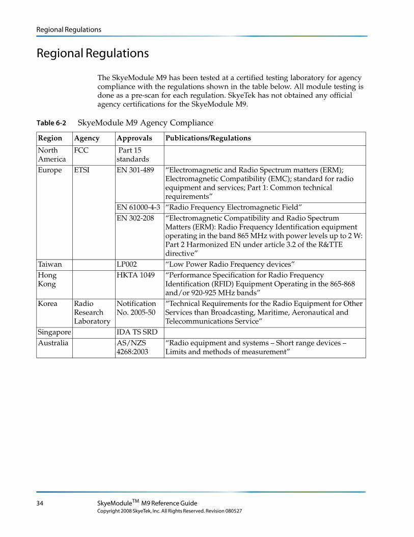
The SkyeModule M9 has been tested at a certified testing laboratory for agency compliance with the regulations shown in the table below. All module testing is done as a pre-scan for each regulation. SkyeTek has not obtained any official agency certifications for the SkyeModule M9.
Table 6-2 SkyeModule M9 Agency Compliance
Region Agency Approvals Publications/Regulations
North America
FCC Part 15 standards
Europe ETSI EN 301-489 “Electromagnetic and Radio Spectrum matters (ERM); Electromagnetic Compatibility (EMC); standard for radio equipment and services; Part 1: Common technical requirements”
EN 61000-4-3 “Radio Frequency Electromagnetic Field”EN 302-208 “Electromagnetic Compatibility and Radio Spectrum
Matters (ERM): Radio Frequency Identification equipment operating in the band 865 MHz with power levels up to 2 W: Part 2 Harmonized EN under article 3.2 of the R&TTE directive”
Taiwan LP002 “Low Power Radio Frequency devices”Hong Kong
HKTA 1049 “Performance Specification for Radio Frequency Identification (RFID) Equipment Operating in the 865-868 and/or 920-925 MHz bands”
Korea Radio Research Laboratory
Notification No. 2005-50
“Technical Requirements for the Radio Equipment for Other Services than Broadcasting, Maritime, Aeronautical and Telecommunications Service”
Singapore IDA TS SRDAustralia AS/NZS
4268:2003“Radio equipment and systems – Short range devices – Limits and methods of measurement”
34 SkyeModuleTM M9 Reference Guide
Copyright 2008 SkyeTek, Inc. All Rights Reserved. Revision 080527
Radio Specifications
Radio Specifications
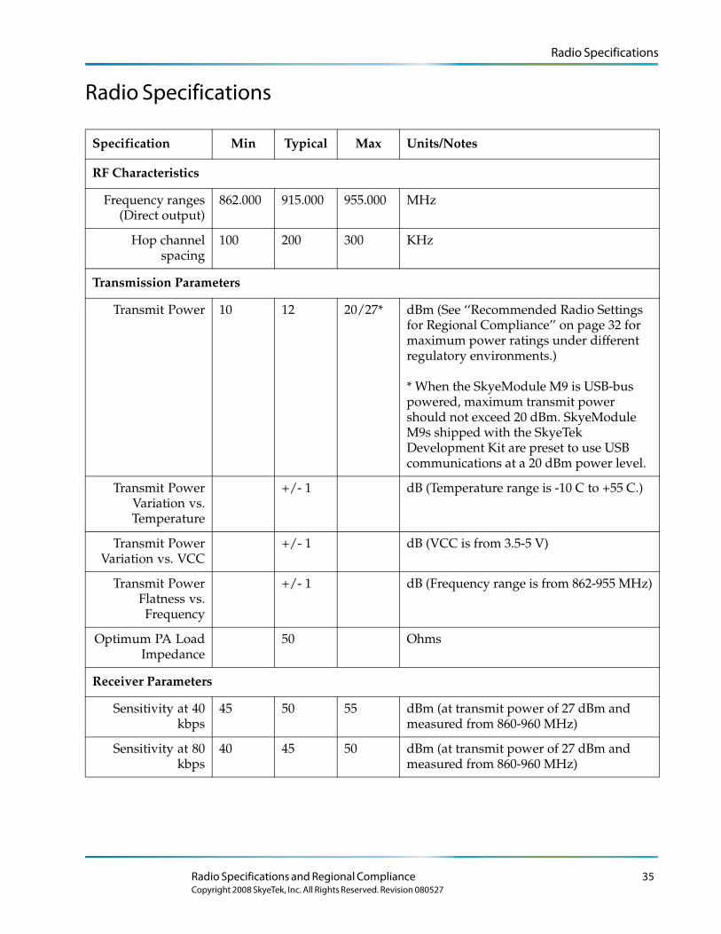
Specification Min Typical Max Units/Notes
RF Characteristics
Frequency ranges (Direct output)
862.000 915.000 955.000 MHz
Hop channel spacing
100 200 300 KHz
Transmission Parameters
Transmit Power 10 12 20/27* dBm (See ‘‘Recommended Radio Settings for Regional Compliance’’ on page 32 for maximum power ratings under different regulatory environments.)
* When the SkyeModule M9 is USB-bus powered, maximum transmit power should not exceed 20 dBm. SkyeModule M9s shipped with the SkyeTek Development Kit are preset to use USB communications at a 20 dBm power level.
Transmit Power Variation vs. Temperature
+/- 1 dB (Temperature range is -10 C to +55 C.)
Transmit Power Variation vs. VCC
+/- 1 dB (VCC is from 3.5-5 V)
Transmit Power Flatness vs. Frequency
+/- 1 dB (Frequency range is from 862-955 MHz)
Optimum PA Load Impedance
50 Ohms
Receiver Parameters
Sensitivity at 40 kbps
45 50 55 dBm (at transmit power of 27 dBm and measured from 860-960 MHz)
Sensitivity at 80 kbps
40 45 50 dBm (at transmit power of 27 dBm and measured from 860-960 MHz)
Radio Specifications and Regional Compliance 35Copyright 2008 SkyeTek, Inc. All Rights Reserved. Revision 080527

Radio Specifications
36 SkyeModuleTM M9 Reference Guide
Copyright 2008 SkyeTek, Inc. All Rights Reserved. Revision 080527
Chapter 7
Antenna Options
The SkyeModule M9 supports any 50 Ohm antenna tuned to the correct frequency range. Read range is highly dependent on antenna selection, tag selection, and operating environment.
Read range depends on your specific settings, including:
● Environment (to maximize accuracy for testing, SkyeTek recommends that you use an outdoor free-space test)
● Antenna gain: a higher-gain antenna provides a longer read range. However, this longer range is achieved through a smaller beam width, which in turn reduces the size of the read field, affecting read reliability.
● Antenna cable length: antenna-cable gain/loss is approximately -0.49 dB/meter (-0.15 dB/foot) for a standard RG58 coaxial cable.
● RF power: maximum RF power is 27 dBm.
● Frequency hopping settings (depends on antenna)
● Antenna polarization
● Tag orientation
● Tag type, manufacturer, and individual tag
● Tag mounting surface
● Tag dynamics (speed, moving, rotating)
L o r e m ip s u m d o lo r s it a me t, c o n s e c te tu e rlo b o r tis p u lv in a r ma g n a . Mo r b i q u is
fe r m e n tu m. In s o d a le s fe u g ia t s e m. S e d u t p e d e . N a m te mp u s . Ma e c e n a s r u tr u mC u r a b itu r n u n c . A e n e a n s c e le r is q u e
S u s p e n d is s e e r a t. Ma u r is u t c uv e s tib u lu m s e m. V iv a mu s e t, v e l le c tu s v ita e
U t o r c i r is u s , c o n v a llis e t, S u s p e n d is s e s u s c ip it v u lp u ta te e lit.
e tr a e n im. S u s p e n d is s e e le me n tu m. S e d e n im lo r e m, s u s c ip it q u is , v e s tib u lu m
in , s u s c ip it n o n , a n te . L o r e m ip s u m d o lo r s it a me t, c o n s e c te tu e r
h a b ita s s e p la te a d ic tu ms t.
S u s p e n d is s e s u s c ip it v u lp u ta te e lit.
. S e d
c o n s e c te tu e r r is u s .
lu c tu s imp e r d ie t.
p r e tiu m c o n d ime n tu m.
Note – The MMCX antenna connector for the M9 allows quick connections but can let a loose antenna cable rotate, yaw, or pitch in the connector socket if you do not secure the cable. Cable motion increases the VSWR to the radio receiver and degrades performance. Make sure that you provide strain relief for the antenna cable to prevent any motion or mechanical stress at the MMCX connector.
37
Copyright 2008 SkyeTek, Inc. All Rights Reserved. Revision 080527

38 SkyeModuleTM M9 Reference Guide
Copyright 2008 SkyeTek, Inc. All Rights Reserved. Revision 080527
Chapter 8
Software Interface Specifications
Host Communication – SkyeTek Protocol v3
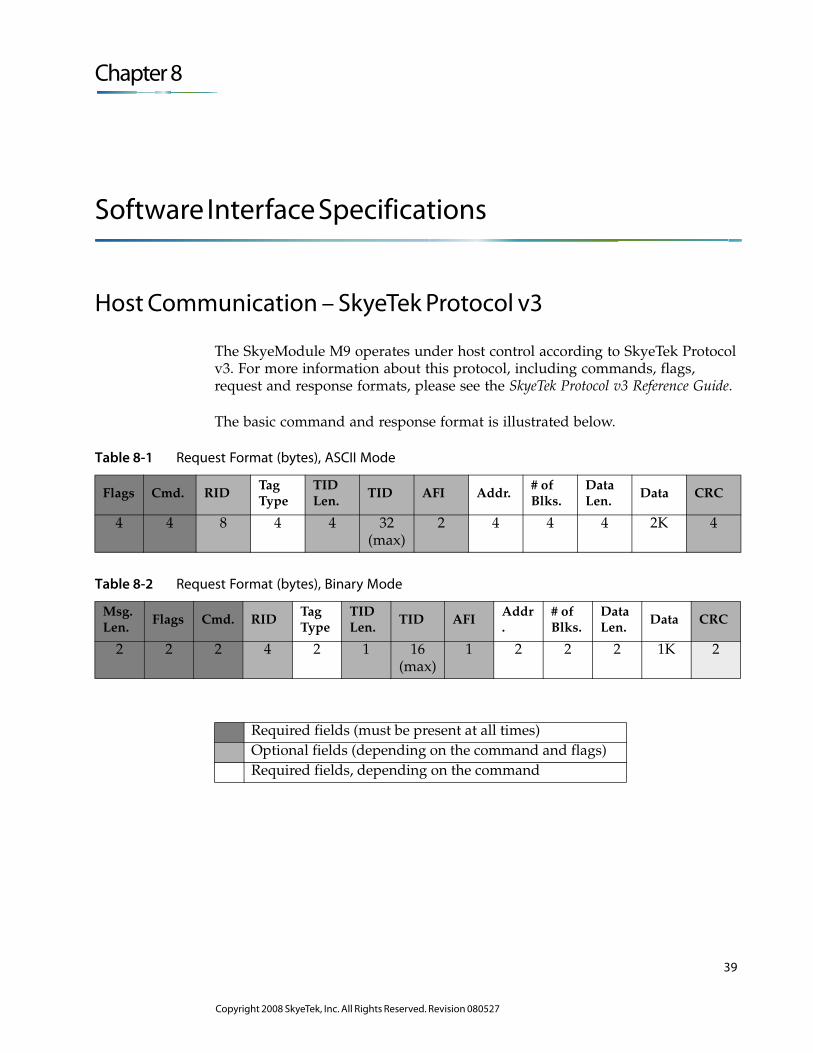
The SkyeModule M9 operates under host control according to SkyeTek Protocol v3. For more information about this protocol, including commands, flags, request and response formats, please see the SkyeTek Protocol v3 Reference Guide.
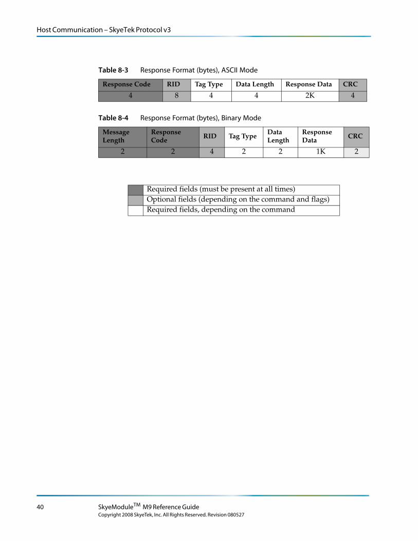
The basic command and response format is illustrated below.
Table 8-1 Request Format (bytes), ASCII Mode
Flags Cmd. RIDTag Type
TID Len.
TID AFI Addr.# of Blks.
Data Len.
Data CRC
4 4 8 4 4 32 (max)
2 4 4 4 2K 4
Table 8-2 Request Format (bytes), Binary Mode
Msg. Len.
Flags Cmd. RIDTag Type
TID Len.
TID AFIAddr.
# of Blks.
Data Len.
Data CRC
2 2 2 4 2 1 16 (max)
1 2 2 2 1K 2
Required fields (must be present at all times)Optional fields (depending on the command and flags)Required fields, depending on the command
39
Copyright 2008 SkyeTek, Inc. All Rights Reserved. Revision 080527
Host Communication – SkyeTek Protocol v3
Table 8-3 Response Format (bytes), ASCII Mode
Response Code RID Tag Type Data Length Response Data CRC
4 8 4 4 2K 4
Table 8-4 Response Format (bytes), Binary Mode
Message Length
Response Code
RID Tag TypeData Length
Response Data
CRC
2 2 4 2 2 1K 2
Required fields (must be present at all times)Optional fields (depending on the command and flags)Required fields, depending on the command
40 SkyeModuleTM M9 Reference Guide
Copyright 2008 SkyeTek, Inc. All Rights Reserved. Revision 080527
Chapter 9
Using Secure Memory
L o r e m ip s u m d o lo r s it a me t, c o n s e c te tu e rlo b o r tis p u lv in a r ma g n a . Mo r b i q u is
fe r m e n tu m. In s o d a le s fe u g ia t s e m. S e d u t p e d e . N a m te mp u s . Ma e c e n a s r u tr u mC u r a b itu r n u n c . A e n e a n s c e le r is q u e
S u s p e n d is s e e r a t. Ma u r is u t c uv e s tib u lu m s e m. V iv a mu s e t, v e l le c tu s v ita e
U t o r c i r is u s , c o n v a llis e t, S u s p e n d is s e s u s c ip it v u lp u ta te e lit.
e tr a e n im. S u s p e n d is s e e le me n tu m. S e d e n im lo r e m, s u s c ip it q u is , v e s tib u lu m
in , s u s c ip it n o n , a n te . L o r e m ip s u m d o lo r s it a me t, c o n s e c te tu e r
h a b ita s s e p la te a d ic tu ms t.
S u s p e n d is s e s u s c ip it v u lp u ta te e lit.
. S e d
c o n s e c te tu e r r is u s .
lu c tu s imp e r d ie t.
p r e tiu m c o n d ime n tu m.
Note – Use of Secure Memory features requires a specific version of the SkyeModule M9 firmware. Please contact your SkyeTek sales representative to obtain the correct firmware.
As part of the ReaderwareTM Security Suite, the Secure Memory feature uses the SkyeModule M9’s firmware to add cryptographic functionality to RFID tags that do not ordinarily have built-in security. Specifically, Secure Memory allows data written to RFID tags to be signed, encrypted, or both. The M9 supports several encryption ciphers (DES, 3DES, and AES) and several cryptographic hash functions (SHA, MD5, and SHA-224/256/384/512) to sign or verify the integrity and authenticity of a message.
When using Secure Memory, the M9 treats the entire tag memory as secure; user-accessible blocks are not needed. The M9 stores algorithm information, initialization vectors, and ciphertext on the tag.
Signing lets you verify data authenticity and integrity. When signing, the reader appends a hash to either plaintext or ciphertext and stores it on the tag along with other header information. By computing the hash using the known shared key and the plaintext and by checking the result against the appended hash, the you can confirm that the message was generated by an authorized user or determine that the tag data on the tag was tampered with or altered during transmission.
Encryption lets you hide plaintext data as ciphertext, obscuring information that is sent over the air or stored on a tag. Only authorized users with the proper key can decode the ciphertext.
This chapter provides examples of using Secure Memory commands. Please contact SkyeTek for more information about the Readerware Security Suite.
41
Copyright 2008 SkyeTek, Inc. All Rights Reserved. Revision 080527
Using Secure Memory Commands
Using Secure Memory Commands
Secure Memory is implemented by issuing a Setup Secure Memory or Initialize Secure Memory commands, described in this chapter.
Once enabled, all security operations are handled transparently for the following commands:
● Read Tag Data
● Write Tag Data
● Get Tag Info
There are two major modes of operation:
● Data Integrity mode. In this mode, there is no encryption, but the reader verifies data integrity. When writing data to a tag, the reader automatically computes a secure hash for the data. The reader writes the data and a hash message authentication code (HMAC) to the tag. When reading the data back from the tag, the reader verifies that the HMAC matches the data that it initially wrote to the tag. If the HMAC does not match, this indicates the data has been corrupted or tampered with, and the reader returns a fail message to the host.
● Encryption and Data Integrity mode. In this mode, the reader verifies the data integrity (as in Data Integrity mode) and encrypts the data. The reader then writes the encrypted data and HMAC to the tag. When reading the data back from the tag, the reader verifies that the HMAC matches the data that it initially wrote to the tag, deciphers the data, and reports the plaintext data to the host. If the data has been altered, the reader returns a fail message to the host.
Other Secure Memory notes:
● You must use the HMAC (data integrity) and Encryption flags with these commands after you begin using Secure Memory.
● Secure Memory automatically reformats the tag for secure use. Thus, block 0 in Secure Memory mode does not correspond to block 0 in the physical tag memory. The Initialize Secure Memory command automatically reserves a number of blocks at the beginning of the tag for algorithm and key information. The command also resizes the tag memory, provides a new user memory size for the tag, and then initializes the user memory area to 0s. For example, if you write to block 0 in Data Integrity mode, you cannot read back the plaintext data from the tag’s physical block 0 location.
● If you try to read the contents of a Secure Memory tag that has been initialized and written in Encryption and Data Integrity mode with a reader that is not in Secure Memory mode, you will read the encrypted text or the initialization information, depending on which block you read from.
42 SkyeModuleTM M9 Reference Guide
Copyright 2008 SkyeTek, Inc. All Rights Reserved. Revision 080527
Using Secure Memory Commands
● If you read the contents of a Secure Memory tag that has been initialized and written in Encryption and Data Integrity mode with a reader that is in Secure memory mode, you can read the plaintext data (as long as the tag has not been tampered with or the data altered).
● Read and write commands are used to read and write to Secure Memory once a Secure Memory session has been initialized. The read and write command should look the same as a normal read an write command to a non-secure-memory tag except that the session flag must be specified and the HMAC_F should be specified if HMAC is used and the ENC_F should be specified if encryption is used.
● After you begin using Secure Memory with a tag, the tag size appears to change. In normal operations, the Get Tag Info command returns the physical memory layout of the tag. In Secure Memory mode, the Get Tag Info command returns the starting block, max block, and number of blocks of the reformatted and available user memory.
● You can stop using Secure Memory functionality by deselecting an initialized tag and then reselecting the tag without the flags set.
L o r e m ip s u m d o lo r s it a me t, c o n s e c te tu e rlo b o r tis p u lv in a r ma g n a . Mo r b i q u is
fe r m e n tu m. In s o d a le s fe u g ia t s e m. S e d u t p e d e . N a m te mp u s . Ma e c e n a s r u tr u mC u r a b itu r n u n c . A e n e a n s c e le r is q u e
S u s p e n d is s e e r a t. Ma u r is u t c uv e s tib u lu m s e m. V iv a mu s e t, v e l le c tu s v ita e
U t o r c i r is u s , c o n v a llis e t, S u s p e n d is s e s u s c ip it v u lp u ta te e lit.
e tr a e n im. S u s p e n d is s e e le me n tu m. S e d e n im lo r e m, s u s c ip it q u is , v e s tib u lu m
in , s u s c ip it n o n , a n te . L o r e m ip s u m d o lo r s it a me t, c o n s e c te tu e r
h a b ita s s e p la te a d ic tu ms t.
S u s p e n d is s e s u s c ip it v u lp u ta te e lit.
. S e d
c o n s e c te tu e r r is u s .
lu c tu s imp e r d ie t.
p r e tiu m c o n d ime n tu m.
Note – If you write to a Secure Memory tag without the HMAC or Encryption flag enabled, you may lose some or all of the data being written. (Reading encrypted data without one of the flags set does not affect the data, although the data appears in its encrypted state.)
Choosing Security Algorithms
Secure memory lets you select the algorithm used to compute the hash message authentication code (HMAC) used by either Data Integrity mode or Encryption with Data Integrity mode (Table 9-1).
● For Data Integrity mode, you can choose any of the Hashes listed in the table.
● For Encryption with Data Integrity mode, you can use any of the hashes below and any of the ciphers.
Using Secure Memory 43Copyright 2008 SkyeTek, Inc. All Rights Reserved. Revision 080527
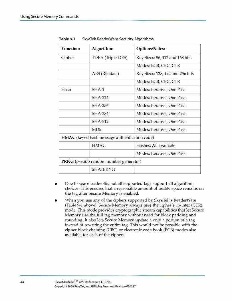
Using Secure Memory Commands
Table 9-1 SkyeTek ReaderWare Security Algorithms
Function: Algorithm: Options/Notes:
Cipher TDEA (Triple-DES) Key Sizes: 56, 112 and 168 bits
Modes: ECB, CBC, CTR
AES (Rijndael) Key Sizes: 128, 192 and 256 bits
Modes: ECB, CBC, CTR
Hash SHA-1 Modes: Iterative, One Pass
SHA-224 Modes: Iterative, One Pass
SHA-256 Modes: Iterative, One Pass
SHA-384 Modes: Iterative, One Pass
SHA-512 Modes: Iterative, One Pass
MD5 Modes: Iterative, One Pass
HMAC (keyed hash message authentication code)
HMAC Hashes: All available
Modes: Iterative, One Pass
PRNG (pseudo random number generator)
SHA1PRNG
● Due to space trade-offs, not all supported tags support all algorithm choices. This ensures that a reasonable amount of usable space remains on the tag after Secure Memory is enabled.
● When you use any of the ciphers supported by SkyeTek’s ReaderWare (Table 9-1 above), Secure Memory always uses the cipher’s counter (CTR) mode. This mode provides cryptographic stream capabilities that let Secure Memory use the full tag memory without need for block padding and rounding. It also lets Secure Memory update a only a portion of a tag instead of rewriting the entire tag. This would not be possible with the cipher block chaining (CBC) or electronic code book (ECB) modes also available for each of the ciphers.
44 SkyeModuleTM M9 Reference Guide
Copyright 2008 SkyeTek, Inc. All Rights Reserved. Revision 080527
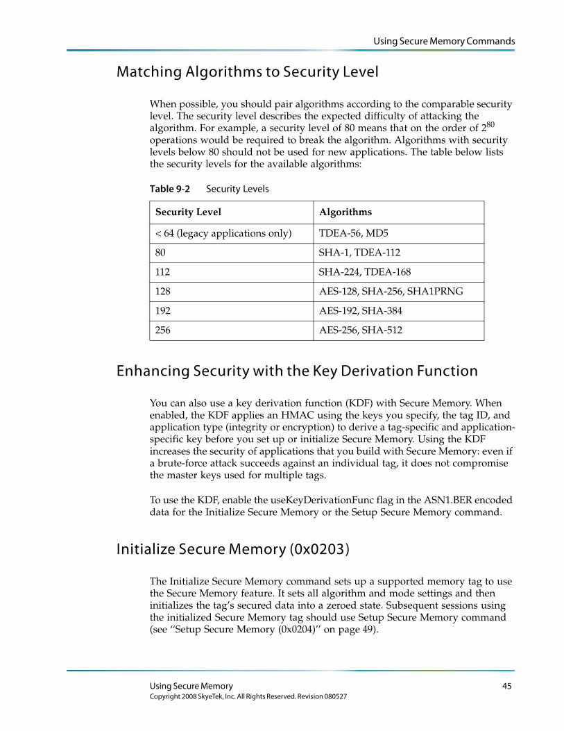
Using Secure Memory Commands
Matching Algorithms to Security Level
When possible, you should pair algorithms according to the comparable security level. The security level describes the expected difficulty of attacking the algorithm. For example, a security level of 80 means that on the order of 280 operations would be required to break the algorithm. Algorithms with security levels below 80 should not be used for new applications. The table below lists the security levels for the available algorithms:
Table 9-2 Security Levels
Security Level Algorithms
< 64 (legacy applications only) TDEA-56, MD5
80 SHA-1, TDEA-112
112 SHA-224, TDEA-168
128 AES-128, SHA-256, SHA1PRNG
192 AES-192, SHA-384
256 AES-256, SHA-512
Enhancing Security with the Key Derivation Function
You can also use a key derivation function (KDF) with Secure Memory. When enabled, the KDF applies an HMAC using the keys you specify, the tag ID, and application type (integrity or encryption) to derive a tag-specific and application-specific key before you set up or initialize Secure Memory. Using the KDF increases the security of applications that you build with Secure Memory: even if a brute-force attack succeeds against an individual tag, it does not compromise the master keys used for multiple tags.
To use the KDF, enable the useKeyDerivationFunc flag in the ASN1.BER encoded data for the Initialize Secure Memory or the Setup Secure Memory command.
Initialize Secure Memory (0x0203)
The Initialize Secure Memory command sets up a supported memory tag to use the Secure Memory feature. It sets all algorithm and mode settings and then initializes the tag’s secured data into a zeroed state. Subsequent sessions using the initialized Secure Memory tag should use Setup Secure Memory command (see ‘‘Setup Secure Memory (0x0204)’’ on page 49).
Using Secure Memory 45Copyright 2008 SkyeTek, Inc. All Rights Reserved. Revision 080527
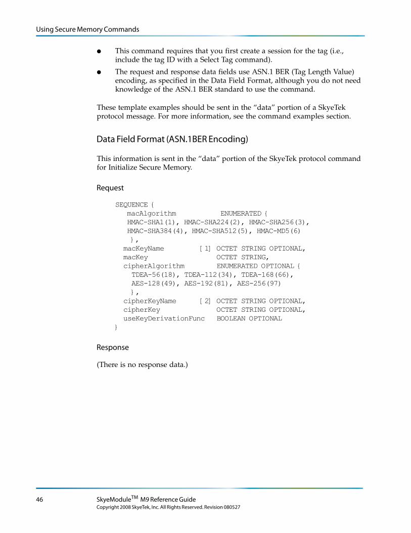
Using Secure Memory Commands
● This command requires that you first create a session for the tag (i.e., include the tag ID with a Select Tag command).
● The request and response data fields use ASN.1 BER (Tag Length Value) encoding, as specified in the Data Field Format, although you do not need knowledge of the ASN.1 BER standard to use the command.
These template examples should be sent in the “data” portion of a SkyeTek protocol message. For more information, see the command examples section.
Data Field Format (ASN.1BER Encoding)
This information is sent in the “data” portion of the SkyeTek protocol command for Initialize Secure Memory.
Request
SEQUENCE {macAlgorithm ENUMERATED {HMAC-SHA1(1), HMAC-SHA224(2), HMAC-SHA256(3), HMAC-SHA384(4), HMAC-SHA512(5), HMAC-MD5(6) },
macKeyName [1] OCTET STRING OPTIONAL, macKey OCTET STRING, cipherAlgorithm ENUMERATED OPTIONAL { TDEA-56(18), TDEA-112(34), TDEA-168(66), AES-128(49), AES-192(81), AES-256(97) }, cipherKeyName [2] OCTET STRING OPTIONAL, cipherKey OCTET STRING OPTIONAL, useKeyDerivationFunc BOOLEAN OPTIONAL}
Response
(There is no response data.)
46 SkyeModuleTM M9 Reference Guide
Copyright 2008 SkyeTek, Inc. All Rights Reserved. Revision 080527
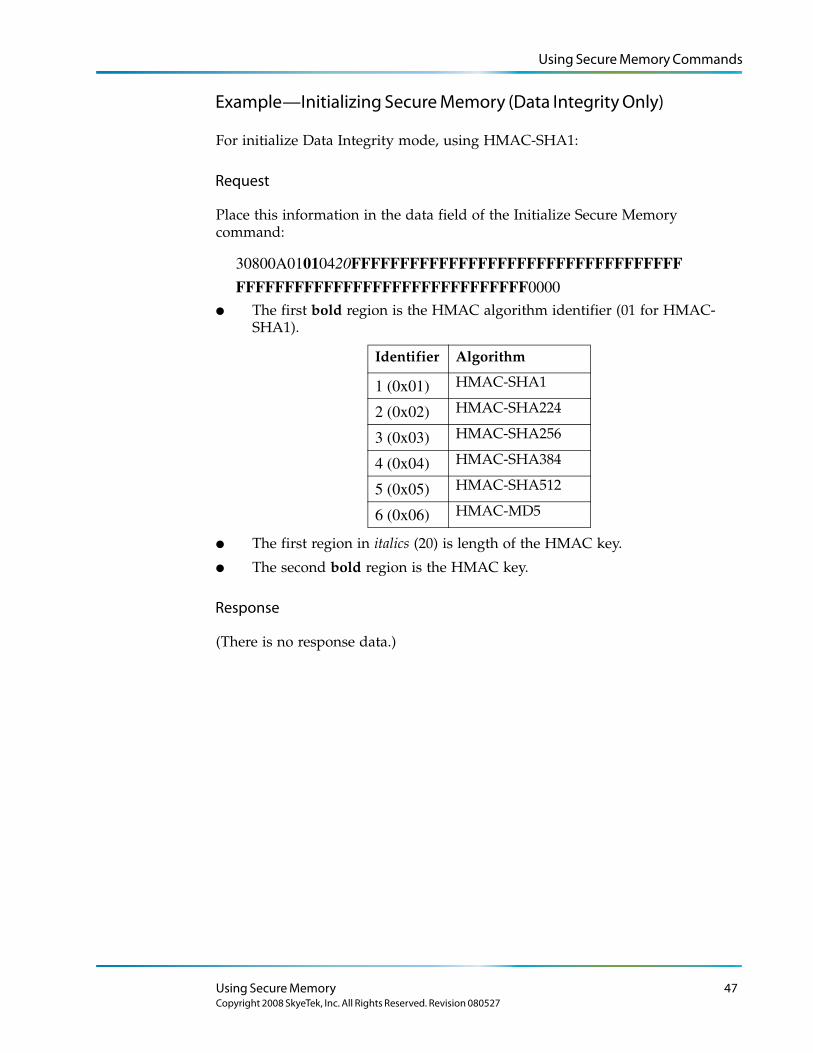
Using Secure Memory Commands
Example—Initializing Secure Memory (Data Integrity Only)
For initialize Data Integrity mode, using HMAC-SHA1:
Request
Place this information in the data field of the Initialize Secure Memory command:
30800A01010420FFFFFFFFFFFFFFFFFFFFFFFFFFFFFFFFFF
FFFFFFFFFFFFFFFFFFFFFFFFFFFFFF0000
● The first bold region is the HMAC algorithm identifier (01 for HMAC-SHA1).
Identifier Algorithm
HMAC-SHA1
HMAC-SHA224
HMAC-SHA256
HMAC-SHA384
HMAC-SHA512
HMAC-MD5
● The first region in italics (20) is length of the HMAC key.
● The second bold region is the HMAC key.
Response
(There is no response data.)
1 (0x01)
2 (0x02)
3 (0x03)
4 (0x04)
5 (0x05)
6 (0x06)
Using Secure Memory 47Copyright 2008 SkyeTek, Inc. All Rights Reserved. Revision 080527
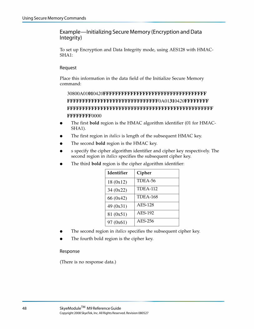
Using Secure Memory Commands
Example—Initializing Secure Memory (Encryption and Data Integrity)
To set up Encryption and Data Integrity mode, using AES128 with HMAC-SHA1:
Request
Place this information in the data field of the Initialize Secure Memory command:
30800A01010420FFFFFFFFFFFFFFFFFFFFFFFFFFFFFFFFFF
FFFFFFFFFFFFFFFFFFFFFFFFFFFFFF0A01310420FFFFFFFF
FFFFFFFFFFFFFFFFFFFFFFFFFFFFFFFFFFFFFFFFFFFFFFFF
FFFFFFFF0000
● The first bold region is the HMAC algorithm identifier (01 for HMAC-SHA1).
● The first region in italics is length of the subsequent HMAC key.
● The second bold region is the HMAC key.
● s specify the cipher algorithm identifier and cipher key respectively. The second region in italics specifies the subsequent cipher key.
● The third bold region is the cipher algorithm identifier:
Identifier Cipher
TDEA-56
TDEA-112
TDEA-168
AES-128
AES-192
AES-256
● The second region in italics specifies the subsequent cipher key.
● The fourth bold region is the cipher key.
Response
(There is no response data.)
18 (0x12)
34 (0x22)
66 (0x42)
49 (0x31)
81 (0x51)
97 (0x61)
48 SkyeModuleTM M9 Reference Guide
Copyright 2008 SkyeTek, Inc. All Rights Reserved. Revision 080527
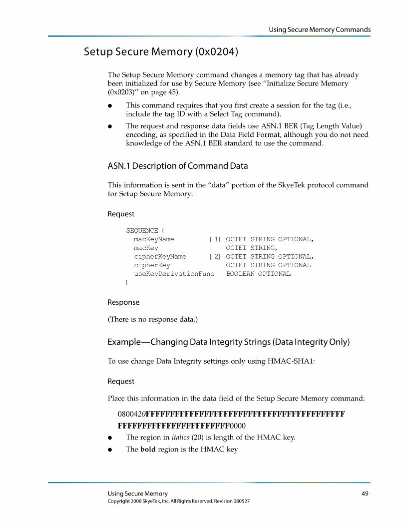
Using Secure Memory Commands
Setup Secure Memory (0x0204)
The Setup Secure Memory command changes a memory tag that has already been initialized for use by Secure Memory (see ‘‘Initialize Secure Memory (0x0203)’’ on page 45).
● This command requires that you first create a session for the tag (i.e., include the tag ID with a Select Tag command).
● The request and response data fields use ASN.1 BER (Tag Length Value) encoding, as specified in the Data Field Format, although you do not need knowledge of the ASN.1 BER standard to use the command.
ASN.1 Description of Command Data
This information is sent in the “data” portion of the SkyeTek protocol command for Setup Secure Memory:
Request
SEQUENCE { macKeyName [1] OCTET STRING OPTIONAL, macKey OCTET STRING, cipherKeyName [2] OCTET STRING OPTIONAL, cipherKey OCTET STRING OPTIONAL useKeyDerivationFunc BOOLEAN OPTIONAL}
Response
(There is no response data.)
Example—Changing Data Integrity Strings (Data Integrity Only)
To use change Data Integrity settings only using HMAC-SHA1:
Request
Place this information in the data field of the Setup Secure Memory command:
0800420FFFFFFFFFFFFFFFFFFFFFFFFFFFFFFFFFFFFFFFFF
FFFFFFFFFFFFFFFFFFFFFFF0000
● The region in italics (20) is length of the HMAC key.
● The bold region is the HMAC key
Using Secure Memory 49Copyright 2008 SkyeTek, Inc. All Rights Reserved. Revision 080527
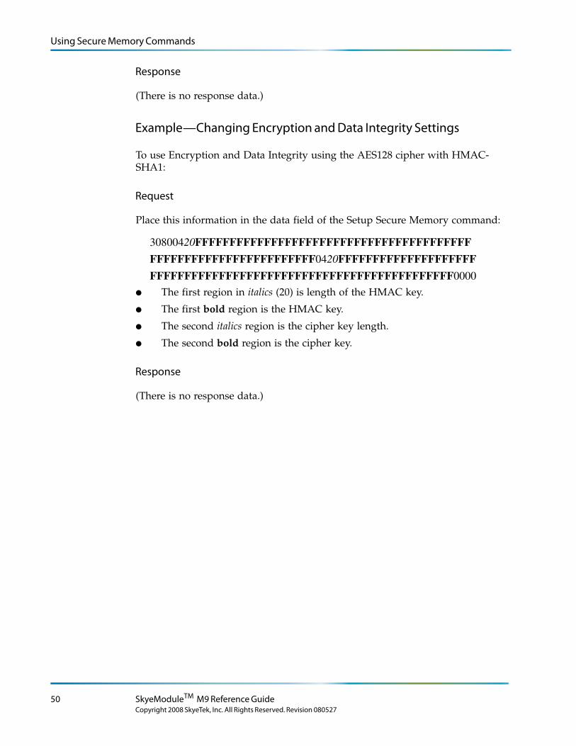
Using Secure Memory Commands
Response
(There is no response data.)
Example—Changing Encryption and Data Integrity Settings
To use Encryption and Data Integrity using the AES128 cipher with HMAC-SHA1:
Request
Place this information in the data field of the Setup Secure Memory command:
30800420FFFFFFFFFFFFFFFFFFFFFFFFFFFFFFFFFFFFFFFF
FFFFFFFFFFFFFFFFFFFFFFFF0420FFFFFFFFFFFFFFFFFFFF
FFFFFFFFFFFFFFFFFFFFFFFFFFFFFFFFFFFFFFFFFFFF0000
● The first region in italics (20) is length of the HMAC key.
● The first bold region is the HMAC key.
● The second italics region is the cipher key length.
● The second bold region is the cipher key.
Response
(There is no response data.)
50 SkyeModuleTM M9 Reference Guide
Copyright 2008 SkyeTek, Inc. All Rights Reserved. Revision 080527
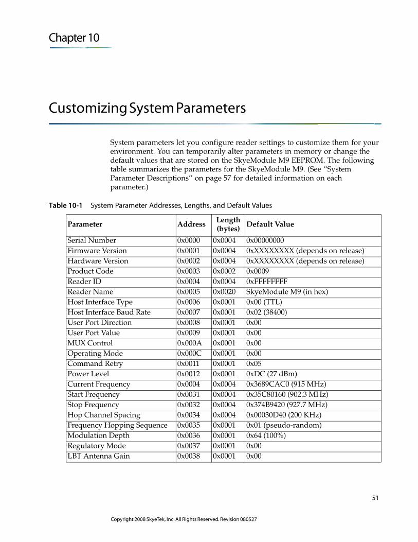
Chapter 10
Customizing System Parameters
System parameters let you configure reader settings to customize them for your environment. You can temporarily alter parameters in memory or change the default values that are stored on the SkyeModule M9 EEPROM. The following table summarizes the parameters for the SkyeModule M9. (See ‘‘System Parameter Descriptions’’ on page 57 for detailed information on each parameter.)
Table 10-1 System Parameter Addresses, Lengths, and Default Values
Parameter Address Length(bytes)
Default Value
Serial Number 0x0000 0x0004 0x00000000Firmware Version 0x0001 0x0004 0xXXXXXXXX (depends on release)Hardware Version 0x0002 0x0004 0xXXXXXXXX (depends on release)Product Code 0x0003 0x0002 0x0009Reader ID 0x0004 0x0004 0xFFFFFFFFReader Name 0x0005 0x0020 SkyeModule M9 (in hex)Host Interface Type 0x0006 0x0001 0x00 (TTL)Host Interface Baud Rate 0x0007 0x0001 0x02 (38400)User Port Direction 0x0008 0x0001 0x00User Port Value 0x0009 0x0001 0x00MUX Control 0x000A 0x0001 0x00Operating Mode 0x000C 0x0001 0x00Command Retry 0x0011 0x0001 0x05Power Level 0x0012 0x0001 0xDC (27 dBm)Current Frequency 0x0004 0x0004 0x3689CAC0 (915 MHz)Start Frequency 0x0031 0x0004 0x35C80160 (902.3 MHz)Stop Frequency 0x0032 0x0004 0x374B9420 (927.7 MHz)Hop Channel Spacing 0x0034 0x0004 0x00030D40 (200 KHz)Frequency Hopping Sequence 0x0035 0x0001 0x01 (pseudo-random)Modulation Depth 0x0036 0x0001 0x64 (100%)Regulatory Mode 0x0037 0x0001 0x00LBT Antenna Gain 0x0038 0x0001 0x00
51
Copyright 2008 SkyeTek, Inc. All Rights Reserved. Revision 080527
Changing System Parameters
Changing System ParametersThe default settings take effect after a power cycle or reset. CAUTION – Changing system parameter values—especially the default
values—can render your SkyeModule M9 nonoperational in your environment. Research, record, and test all planned changes to make sure they are compatible with your system.
You can read or write system parameters via the following commands:
● Read System Parameter—reads the current value of the system parameter at the memory address specified.
● Write System Parameter—writes a new value to the system parameter at the memory address specified.
● Store Default System Parameter—writes a new system parameter value to the EEPROM.
● Retrieve Default System Parameter—reads the system parameter value at the address specified out of EEPROM.
See the SkyeTek Protocol v3 Reference Guide for a complete list of commands.
See ‘‘Understanding System Parameter Formats’’ on page 53 for more information about using these commands.
See ‘‘System Parameter Descriptions’’ on page 57 for information about individual parameters.
The default settings take effect after a power cycle or reset. CAUTION – Resetting (cycling power) on your SkyeModule M9 causes all system parameters to revert to their default values. Any changes made to system parameters in memory are lost at reset unless you write them to the EEPROM as the new default values. Any changes to the default values do not take effect until the reader is reset.
52 SkyeModuleTM M9 Reference Guide
Copyright 2008 SkyeTek, Inc. All Rights Reserved. Revision 080527
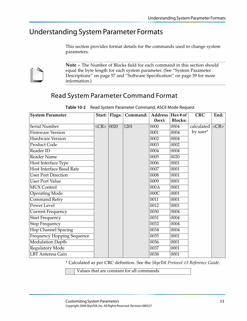
Understanding System Parameter Formats
Understanding System Parameter Formats
This section provides format details for the commands used to change system parameters.
L o r e m ip s u m d o lo r s it a me t, c o n s e c te tu e rlo b o r tis p u lv in a r ma g n a . Mo r b i q u is
fe r m e n tu m. In s o d a le s fe u g ia t s e m. S e d u t p e d e . N a m te mp u s . Ma e c e n a s r u tr u mC u r a b itu r n u n c . A e n e a n s c e le r is q u e
S u s p e n d is s e e r a t. Ma u r is u t c uv e s tib u lu m s e m. V iv a mu s e t, v e l le c tu s v ita e
U t o r c i r is u s , c o n v a llis e t, S u s p e n d is s e s u s c ip it v u lp u ta te e lit.
e tr a e n im. S u s p e n d is s e e le me n tu m. S e d e n im lo r e m, s u s c ip it q u is , v e s tib u lu m
in , s u s c ip it n o n , a n te . L o r e m ip s u m d o lo r s it a me t, c o n s e c te tu e r
h a b ita s s e p la te a d ic tu ms t.
S u s p e n d is s e s u s c ip it v u lp u ta te e lit.
. S e d
c o n s e c te tu e r r is u s .
lu c tu s imp e r d ie t.
p r e tiu m c o n d ime n tu m.
Note – The Number of Blocks field for each command in this section should equal the byte length for each system parameter. (See ‘‘System Parameter Descriptions’’ on page 57 and ‘‘Software Specification’’ on page 39 for more information.)
Read System Parameter Command Format
Table 10-2
System Parameter Start: Flags: Command: Address(hex):
Hex # of Blocks:
CRC End:
Serial Number <CR> 0020 1201 0000 0004 calculated by user*
<CR>Firmware Version 0001 0004Hardware Version 0002 0004Product Code 0003 0002Reader ID 0004 0004Reader Name 0005 0020Host Interface Type 0006 0001Host Interface Baud Rate 0007 0001User Port Direction 0008 0001User Port Value 0009 0001MUX Control 000A 0001Operating Mode 000C 0001Command Retry 0011 0001Power Level 0012 0001Current Frequency 0030 0004Start Frequency 0031 0004Stop Frequency 0032 0004Hop Channel Spacing 0034 0004Frequency Hopping Sequence 0035 0001Modulation Depth 0036 0001Regulatory Mode 0037 0001LBT Antenna Gain 0038 0001
Read System Parameter Command, ASCII Mode Request
* Calculated as per CRC definition. See the SkyeTek Protocol v3 Reference Guide.
Values that are constant for all commands
Customizing System Parameters 53Copyright 2008 SkyeTek, Inc. All Rights Reserved. Revision 080527
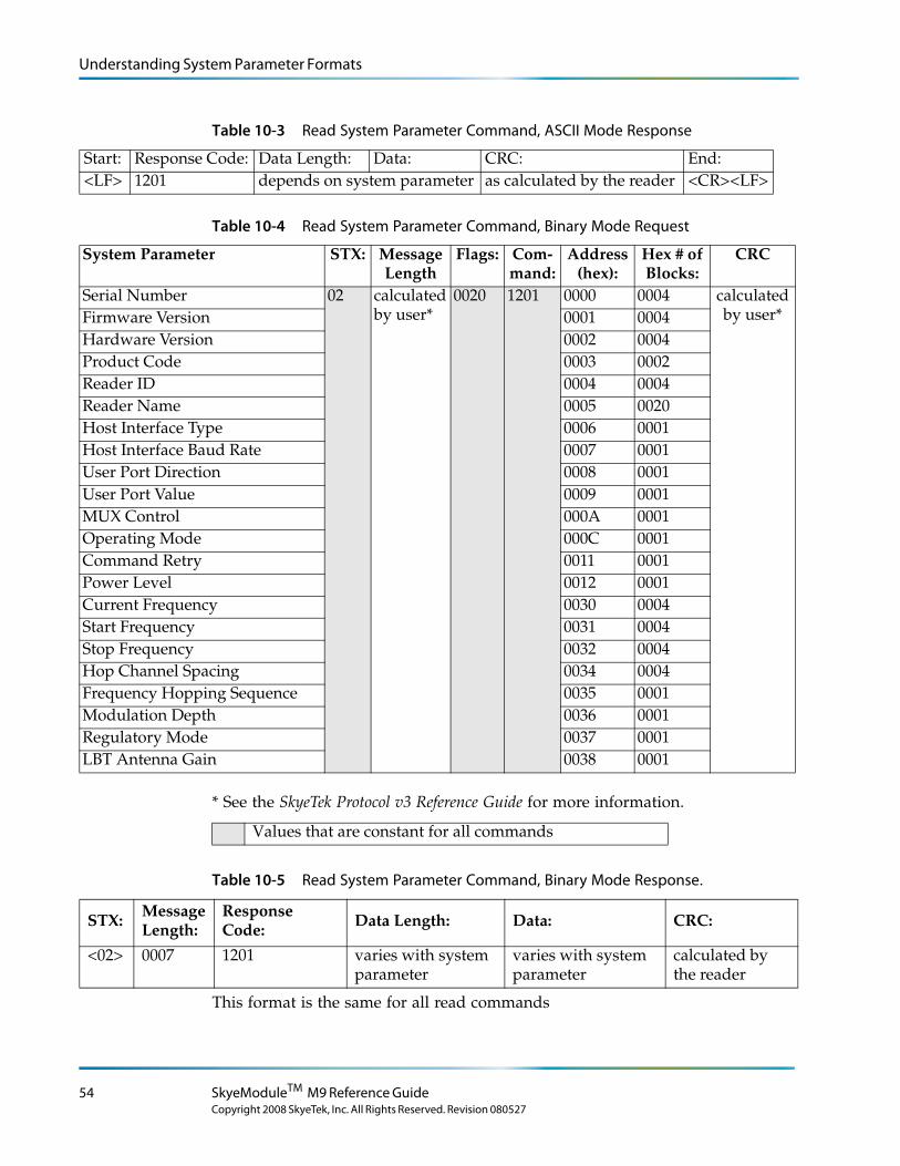
Understanding System Parameter Formats
Table 10-3 Read System Parameter Command, ASCII Mode Response
Start: Response Code: Data Length: Data: CRC: End:<LF> 1201 depends on system parameter as calculated by the reader <CR><LF>
Table 10-4
System Parameter STX: Message Length
Flags: Com-mand:
Address (hex):
Hex # of Blocks:
CRC
Serial Number 02 calculated by user*
0020 1201 0000 0004 calculated by user*Firmware Version 0001 0004
Hardware Version 0002 0004Product Code 0003 0002Reader ID 0004 0004Reader Name 0005 0020Host Interface Type 0006 0001Host Interface Baud Rate 0007 0001User Port Direction 0008 0001User Port Value 0009 0001MUX Control 000A 0001Operating Mode 000C 0001Command Retry 0011 0001Power Level 0012 0001Current Frequency 0030 0004Start Frequency 0031 0004Stop Frequency 0032 0004Hop Channel Spacing 0034 0004Frequency Hopping Sequence 0035 0001Modulation Depth 0036 0001Regulatory Mode 0037 0001LBT Antenna Gain 0038 0001
Read System Parameter Command, Binary Mode Request
* See the SkyeTek Protocol v3 Reference Guide for more information.
Values that are constant for all commands
Table 10-5 Read System Parameter Command, Binary Mode Response.
STX:Message Length:
Response Code: Data Length: Data: CRC:
<02> 0007 1201 varies with system parameter
varies with system parameter
calculated by the reader
This format is the same for all read commands
54 SkyeModuleTM M9 Reference Guide
Copyright 2008 SkyeTek, Inc. All Rights Reserved. Revision 080527
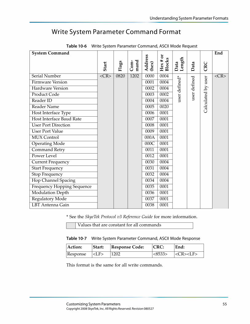
Understanding System Parameter Formats
Write System Parameter Command Format
Table 10-6
System Command
Sta
rt
Flag
s
Com
- m
and
Ad
dre
ss
(hex
)
Hex
# o
r
Blo
cks
Dat
a
Len
gth
Dat
a
CR
C
End
Serial Number <CR> 0820 1202 0000 0004
user
def
ined
*
user
def
ined
Cal
cula
ted
by
user <CR>
Firmware Version 0001 0004Hardware Version 0002 0004Product Code 0003 0002Reader ID 0004 0004Reader Name 0005 0020Host Interface Type 0006 0001Host Interface Baud Rate 0007 0001User Port Direction 0008 0001User Port Value 0009 0001MUX Control 000A 0001Operating Mode 000C 0001Command Retry 0011 0001Power Level 0012 0001Current Frequency 0030 0004Start Frequency 0031 0004Stop Frequency 0032 0004Hop Channel Spacing 0034 0004Frequency Hopping Sequence 0035 0001Modulation Depth 0036 0001Regulatory Mode 0037 0001LBT Antenna Gain 0038 0001
Write System Parameter Command, ASCII Mode Request
* See the SkyeTek Protocol v3 Reference Guide for more information.
Values that are constant for all commands
Table 10-7 Write System Parameter Command, ASCII Mode Response
Action: Start: Response Code: CRC: End:
Response <LF> 1202 <8533> <CR><LF>
This format is the same for all write commands.
Customizing System Parameters 55Copyright 2008 SkyeTek, Inc. All Rights Reserved. Revision 080527
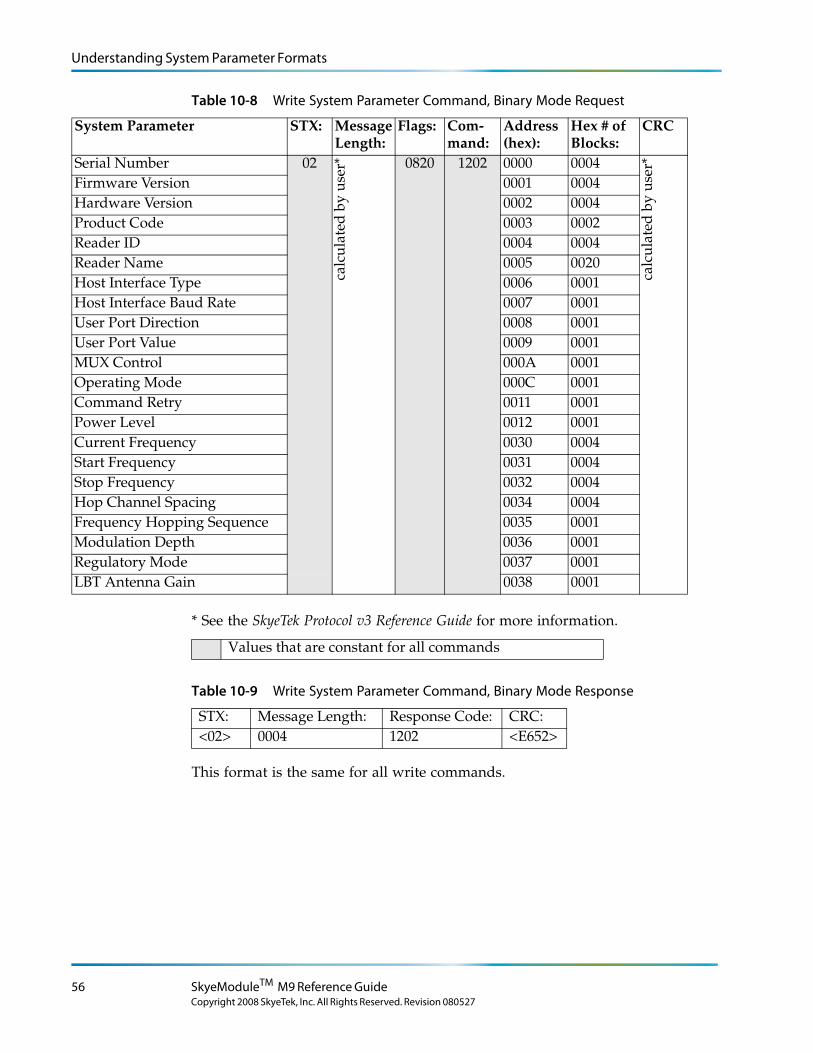
Understanding System Parameter Formats
Table 10-8
System Parameter STX: Message Length:
Flags: Com-mand:
Address (hex):
Hex # of Blocks:
CRC
Serial Number 02
calc
ulat
ed b
y us
er* 0820 1202 0000 0004
calc
ulat
ed b
y us
er*
Firmware Version 0001 0004Hardware Version 0002 0004Product Code 0003 0002Reader ID 0004 0004Reader Name 0005 0020Host Interface Type 0006 0001Host Interface Baud Rate 0007 0001User Port Direction 0008 0001User Port Value 0009 0001MUX Control 000A 0001Operating Mode 000C 0001Command Retry 0011 0001Power Level 0012 0001Current Frequency 0030 0004Start Frequency 0031 0004Stop Frequency 0032 0004Hop Channel Spacing 0034 0004Frequency Hopping Sequence 0035 0001Modulation Depth 0036 0001Regulatory Mode 0037 0001LBT Antenna Gain 0038 0001
Write System Parameter Command, Binary Mode Request
* See the SkyeTek Protocol v3 Reference Guide for more information.
Values that are constant for all commands
Table 10-9 Write System Parameter Command, Binary Mode Response
STX: Message Length: Response Code: CRC:<02> 0004 1202 <E652>
This format is the same for all write commands.
56 SkyeModuleTM M9 Reference Guide
Copyright 2008 SkyeTek, Inc. All Rights Reserved. Revision 080527
System Parameter Descriptions
System Parameter Descriptions
This section describes the SkyeModule M9 system parameters. See ‘‘Understanding System Parameter Formats’’ on page 53 for formats to use each parameter in a system command.
Serial Number
● Returns the serial number of the reader
● Parameter address: 0x0000
● Length (bytes): 4
● Default value: 0x00000000
● Read-only
Firmware Version
● Returns the firmware version currently loaded on the reader
● Refer to the SkyeModule M9 Release Notes for more information about the firmware release.
● Parameter address: 0x0001
● Length (bytes): 4
● Default value: 0xXXXXXXXX (depending on release)
● The firmware version uses this format: f. Major revision (1 Byte)g. Minor revision (1 Byte)h. Current build number (2 bytes)
● Read-only
Hardware Version
● Returns the current hardware version of the reader
● Parameter address: 0x0002
● Length (bytes): 4
● Default value: 0xXXXXXXXX (depending on release)
● The hardware version uses the following format: a. Major revision (1 Byte)
Customizing System Parameters 57Copyright 2008 SkyeTek, Inc. All Rights Reserved. Revision 080527
System Parameter Descriptions
b. Minor revision (1 Byte)c. Current build number (2 bytes)
● Read-only
Product Code
● Returns the SkyeTek product code identifier. (Each SkyeTek product has a unique product code.)
● Parameter address: 0x0003
● Length (bytes): 2
● Default value: 0x0009
● Read-only
Reader ID
● Specifies the Reader ID, which is a reader-specific identifier. It lets the reader execute and respond only to those commands intended for it. The reader determines if the Reader ID in the request matches its internal Reader ID. If the ID does not match, the reader does not respond.
● Parameter address: 0x0004
● Length (bytes): 4
● Default value: 0xFFFFFFFF (depending on release)
● Select the Reader ID functionality by specifying the RID Flag in the request. This setting lets you use multiple readers on the same bus or networked together.
● Read/write
L o r e m ip s u m d o lo r s it a me t, c o n s e c te tu e rlo b o r tis p u lv in a r ma g n a . Mo r b i q u is
fe r m e n tu m. In s o d a le s fe u g ia t s e m. S e d u t p e d e . N a m te mp u s . Ma e c e n a s r u tr u mC u r a b itu r n u n c . A e n e a n s c e le r is q u e
S u s p e n d is s e e r a t. Ma u r is u t c uv e s tib u lu m s e m. V iv a mu s e t, v e l le c tu s v ita e
U t o r c i r is u s , c o n v a llis e t, S u s p e n d is s e s u s c ip it v u lp u ta te e lit.
e tr a e n im. S u s p e n d is s e e le me n tu m. S e d e n im lo r e m, s u s c ip it q u is , v e s tib u lu m
in , s u s c ip it n o n , a n te . L o r e m ip s u m d o lo r s it a me t, c o n s e c te tu e r
h a b ita s s e p la te a d ic tu ms t.
S u s p e n d is s e s u s c ip it v u lp u ta te e lit.
. S e d
c o n s e c te tu e r r is u s .
lu c tu s imp e r d ie t.
p r e tiu m c o n d ime n tu m.
Note – Changing the reader ID from the factory default of FFFFFFFF to any other value disables Loop Mode, which is used for read range demonstrations. See ‘‘Selecting Any Supported Tag Continuously (Loop Mode)’’ on page 70 for an example of using Loop Mode.
58 SkyeModuleTM M9 Reference Guide
Copyright 2008 SkyeTek, Inc. All Rights Reserved. Revision 080527
System Parameter Descriptions
Reader Name
● Identifies a reader with a 32-byte user-defined name.
● Parameter address: 0x0005
● Length (bytes): 32
● Default value: SkyeModule M9 (in hex)
● Read/write
Host Interface Type
● Identifies the type of host interface for the reader to use.
● Parameter address: 0x0006
● Length (bytes): 1
● Default value: 0x00 (TTL)
● Valid host interface values are:
● 0x00 – TTL
● 0x01 – TTL Serial
● 0x03 – SPI
● 0x04 – I2C
● 0x06 – USB
● Any other values are invalid and are ignored.
● Read/write
L o r e m ip s u m d o lo r s it a me t, c o n s e c te tu e rlo b o r tis p u lv in a r ma g n a . Mo r b i q u is
fe r m e n tu m. In s o d a le s fe u g ia t s e m. S e d u t p e d e . N a m te mp u s . Ma e c e n a s r u tr u mC u r a b itu r n u n c . A e n e a n s c e le r is q u e
S u s p e n d is s e e r a t. Ma u r is u t c uv e s tib u lu m s e m. V iv a mu s e t, v e l le c tu s v ita e
U t o r c i r is u s , c o n v a llis e t, S u s p e n d is s e s u s c ip it v u lp u ta te e lit.
e tr a e n im. S u s p e n d is s e e le me n tu m. S e d e n im lo r e m, s u s c ip it q u is , v e s tib u lu m
in , s u s c ip it n o n , a n te . L o r e m ip s u m d o lo r s it a me t, c o n s e c te tu e r
h a b ita s s e p la te a d ic tu ms t.
S u s p e n d is s e s u s c ip it v u lp u ta te e lit.
. S e d
c o n s e c te tu e r r is u s .
lu c tu s imp e r d ie t.
p r e tiu m c o n d ime n tu m.
Note – SkyeModule M9s shipped with the SkyeTek Development Kit are preset to use USB communications.
Host Interface Baud Rate
● Sets the baud rate of the host interface.
● Parameter address: 0x0007
● Length (bytes): 1
● Default value: 0x02 (38,400)
● Works for the TTL Serial host interface only
Customizing System Parameters 59Copyright 2008 SkyeTek, Inc. All Rights Reserved. Revision 080527
System Parameter Descriptions
● Valid baud rate values are:
● 0x01 – 19,200
● 0x02 – 38,400
● 0x03 – 57,600
● 0x04 – 115,200
● Specifying any other value sets the baud rate to 9,600
● Write-only
L o r e m ip s u m d o lo r s it a me t, c o n s e c te tu e rlo b o r tis p u lv in a r ma g n a . Mo r b i q u is
fe r m e n tu m. In s o d a le s fe u g ia t s e m. S e d u t p e d e . N a m te mp u s . Ma e c e n a s r u tr u mC u r a b itu r n u n c . A e n e a n s c e le r is q u e
S u s p e n d is s e e r a t. Ma u r is u t c uv e s tib u lu m s e m. V iv a mu s e t, v e l le c tu s v ita e
U t o r c i r is u s , c o n v a llis e t, S u s p e n d is s e s u s c ip it v u lp u ta te e lit.
e tr a e n im. S u s p e n d is s e e le me n tu m. S e d e n im lo r e m, s u s c ip it q u is , v e s tib u lu m
in , s u s c ip it n o n , a n te . L o r e m ip s u m d o lo r s it a me t, c o n s e c te tu e r
h a b ita s s e p la te a d ic tu ms t.
S u s p e n d is s e s u s c ip it v u lp u ta te e lit.
. S e d
c o n s e c te tu e r r is u s .
lu c tu s imp e r d ie t.
p r e tiu m c o n d ime n tu m.
Note – For firmware updates, you may need to limit the baud rate to 38,400.
User Port Direction
● Sets the direction of the GPIO pins of the reader.
● Parameter address: 0x0008
● Length (bytes): 1
● Default value: 0x00
● A one in the bit position indicates that the corresponding GPIO pin is an input.
● A zero in the bit position indicates that the corresponding GPIO pin is an output.
● Bits correspond to the pins as follows:
● BIT0 – GPIO 0
● BIT1 – GPIO 1
● BIT2 – GPIO 2
● BIT3 – GPIO 3 (not available for user I/O)
● BIT4 – GPIO 4
● BIT5 – GPIO 5
● BIT6 – GPIO 6
● BIT7 – reserved for future use
● Read/write
60 SkyeModuleTM M9 Reference Guide
Copyright 2008 SkyeTek, Inc. All Rights Reserved. Revision 080527
System Parameter Descriptions
User Port Value
● Sets the value of the GPIO pins of the reader.
● Parameter address: 0x0009
● Length (bytes): 1
● Default value: 0x00
● A one in the bit position indicates that the corresponding GPIO pin is a logic high.
● A zero in the bit position indicates that the corresponding GPIO pin is logic low.
● The enable bit (bit 7) must be set for the settings to take effect.
● Bits correspond to the pins as follows:
● BIT0 – GPIO 0
● BIT1 – GPIO 1
● BIT2 – GPIO 2
● BIT3 – GPIO 3 (not available for user I/O)
● BIT4 – GPIO 4
● BIT5 – GPIO 5
● BIT6 – GPIO 6
● BIT7 – enable
● Read/write
MUX Control
● Controls a SkyePlus multiplexer. See the SkyePlus Multiplexer Reference Guide for complete information about using this parameter.
● Parameter address: 0x000A
● Length (bytes): 1
● Default value: 0x00
● Read/write
Customizing System Parameters 61Copyright 2008 SkyeTek, Inc. All Rights Reserved. Revision 080527
System Parameter Descriptions
Operating Mode
● Puts the reader into sleep mode.
● Parameter address: 0x000C
● Length (bytes): 1
● Default value: 0x00
● Writing a value 0x01 to this parameter puts the reader into sleep mode.
● Sending any command on any interface wakes the reader from sleep mode.
● Read/write
L o r e m ip s u m d o lo r s it a me t, c o n s e c te tu e rlo b o r tis p u lv in a r ma g n a . Mo r b i q u is
fe r m e n tu m. In s o d a le s fe u g ia t s e m. S e d u t p e d e . N a m te mp u s . Ma e c e n a s r u tr u mC u r a b itu r n u n c . A e n e a n s c e le r is q u e
S u s p e n d is s e e r a t. Ma u r is u t c uv e s tib u lu m s e m. V iv a mu s e t, v e l le c tu s v ita e
U t o r c i r is u s , c o n v a llis e t, S u s p e n d is s e s u s c ip it v u lp u ta te e lit.
e tr a e n im. S u s p e n d is s e e le me n tu m. S e d e n im lo r e m, s u s c ip it q u is , v e s tib u lu m
in , s u s c ip it n o n , a n te . L o r e m ip s u m d o lo r s it a me t, c o n s e c te tu e r
h a b ita s s e p la te a d ic tu ms t.
S u s p e n d is s e s u s c ip it v u lp u ta te e lit.
. S e d
c o n s e c te tu e r r is u s .
lu c tu s imp e r d ie t.
p r e tiu m c o n d ime n tu m.
Note – Sleep mode is not supported when the SkyeModule reader uses the USB host interface.
Command Retry
● One-byte value.
● Parameter address: 0x0011
● Length (bytes): 1
● Default value: 0x05
● Can be set by the host.
● Specifies the number of times a tag command is executed internally in the reader before responding with a failure response.
● Applies only to tag-specific SkyeTek Protocol commands.
● Valid range of values is 0-255 (0x00–0xFF).
● The command is repeated internally “n” number of times, where n is the value specified by the host, unless there is a successful response. When a successful response occurs, the reader stops repeating the command and sends a success response back to the host.
● Read/write
Note – Increasing the value for this parameter increases the time that the reader takes before it sends a failure message when a failure occurs. To avoid unnecessary delays, be sure to determine the optimal number of retries for your particular use.
62 SkyeModuleTM M9 Reference Guide
Copyright 2008 SkyeTek, Inc. All Rights Reserved. Revision 080527
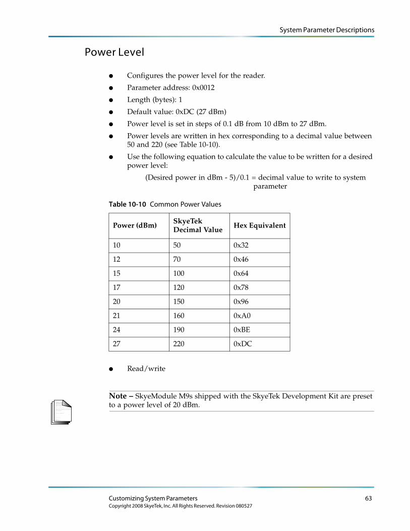
System Parameter Descriptions
Power Level
● Configures the power level for the reader.
● Parameter address: 0x0012
● Length (bytes): 1
● Default value: 0xDC (27 dBm)
● Power level is set in steps of 0.1 dB from 10 dBm to 27 dBm.
● Power levels are written in hex corresponding to a decimal value between 50 and 220 (see Table 10-10).
● Use the following equation to calculate the value to be written for a desired power level:
(Desired power in dBm - 5)/0.1 = decimal value to write to system parameter
Table 10-10 Common Power Values
Power (dBm) SkyeTek Decimal Value Hex Equivalent
10 50 0x32
12 70 0x46
15 100 0x64
17 120 0x78
20 150 0x96
21 160 0xA0
24 190 0xBE
27 220 0xDC
● Read/write
L o r e m ip s u m d o lo r s it a me t, c o n s e c te tu e rlo b o r tis p u lv in a r ma g n a . Mo r b i q u is
fe r m e n tu m. In s o d a le s fe u g ia t s e m. S e d u t p e d e . N a m te mp u s . Ma e c e n a s r u tr u mC u r a b itu r n u n c . A e n e a n s c e le r is q u e
S u s p e n d is s e e r a t. Ma u r is u t c uv e s tib u lu m s e m. V iv a mu s e t, v e l le c tu s v ita e
U t o r c i r is u s , c o n v a llis e t, S u s p e n d is s e s u s c ip it v u lp u ta te e lit.
e tr a e n im. S u s p e n d is s e e le me n tu m. S e d e n im lo r e m, s u s c ip it q u is , v e s tib u lu m
in , s u s c ip it n o n , a n te . L o r e m ip s u m d o lo r s it a me t, c o n s e c te tu e r
h a b ita s s e p la te a d ic tu ms t.
S u s p e n d is s e s u s c ip it v u lp u ta te e lit.
. S e d
c o n s e c te tu e r r is u s .
lu c tu s imp e r d ie t.
p r e tiu m c o n d ime n tu m.
Note – SkyeModule M9s shipped with the SkyeTek Development Kit are preset to a power level of 20 dBm.
Customizing System Parameters 63Copyright 2008 SkyeTek, Inc. All Rights Reserved. Revision 080527
System Parameter Descriptions
Current Frequency
● Sets the current frequency with which the reader singulates a tag.
● Parameter address: 0x0030
● Length (bytes): 4
● Default value: 0x3689CAC0 (915 MHz)
● This parameter is a 4-byte hex equivalent of the frequency. Table 10-11 shows hex values for commonly used frequencies.
● Read/write
L o r e m ip s u m d o lo r s it a me t, c o n s e c te tu e rlo b o r tis p u lv in a r ma g n a . Mo r b i q u is
fe r m e n tu m. In s o d a le s fe u g ia t s e m. S e d u t p e d e . N a m te mp u s . Ma e c e n a s r u tr u mC u r a b itu r n u n c . A e n e a n s c e le r is q u e
S u s p e n d is s e e r a t. Ma u r is u t c uv e s tib u lu m s e m. V iv a mu s e t, v e l le c tu s v ita e
U t o r c i r is u s , c o n v a llis e t, S u s p e n d is s e s u s c ip it v u lp u ta te e lit.
e tr a e n im. S u s p e n d is s e e le me n tu m. S e d e n im lo r e m, s u s c ip it q u is , v e s tib u lu m
in , s u s c ip it n o n , a n te . L o r e m ip s u m d o lo r s it a me t, c o n s e c te tu e r
h a b ita s s e p la te a d ic tu ms t.
S u s p e n d is s e s u s c ip it v u lp u ta te e lit.
. S e d
c o n s e c te tu e r r is u s .
lu c tu s imp e r d ie t.
p r e tiu m c o n d ime n tu m.
Note – See ‘‘Recommended Radio Settings for Regional Compliance’’ on page 34 to view compliance information and recommended reader settings.
Start Frequency
● Sets the low end of the frequency range under which the reader operates.
● Parameter address: 0x0031
● Length (bytes): 4
● Default value: 0x35C80160 (902.3 MHz)
● This parameter is written with a 4-byte hex equivalent of the frequency desired. See Table 10-11 for commonly used frequencies and their hex values.
● To enable frequency hopping, set a frequency range using the Start Frequency and Stop Frequency system parameters. Then use the Frequency Hopping Sequence parameter to set the frequency hopping mode (either sequential or pseudo-random). To disable frequency hopping, set the Start Frequency and Stop Frequency parameter to the same value.
● Read/write
L o r e m ip s u m d o lo r s it a me t, c o n s e c te tu e rlo b o r tis p u lv in a r ma g n a . Mo r b i q u is
fe r m e n tu m. In s o d a le s fe u g ia t s e m. S e d u t p e d e . N a m te mp u s . Ma e c e n a s r u tr u mC u r a b itu r n u n c . A e n e a n s c e le r is q u e
S u s p e n d is s e e r a t. Ma u r is u t c uv e s tib u lu m s e m. V iv a mu s e t, v e l le c tu s v ita e
U t o r c i r is u s , c o n v a llis e t, S u s p e n d is s e s u s c ip it v u lp u ta te e lit.
e tr a e n im. S u s p e n d is s e e le me n tu m. S e d e n im lo r e m, s u s c ip it q u is , v e s tib u lu m
in , s u s c ip it n o n , a n te . L o r e m ip s u m d o lo r s it a me t, c o n s e c te tu e r
h a b ita s s e p la te a d ic tu ms t.
S u s p e n d is s e s u s c ip it v u lp u ta te e lit.
. S e d
c o n s e c te tu e r r is u s .
lu c tu s imp e r d ie t.
p r e tiu m c o n d ime n tu m.
Note – See ‘‘Recommended Radio Settings for Regional Compliance’’ on page 32 to view compliance information and recommended reader settings.
64 SkyeModuleTM M9 Reference Guide
Copyright 2008 SkyeTek, Inc. All Rights Reserved. Revision 080527
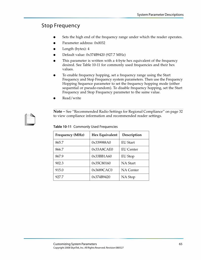
System Parameter Descriptions
Stop Frequency
● Sets the high end of the frequency range under which the reader operates.
● Parameter address: 0x0032
● Length (bytes): 4
● Default value: 0x374B9420 (927.7 MHz)
● This parameter is written with a 4-byte hex equivalent of the frequency desired. See Table 10-11 for commonly used frequencies and their hex values.
● To enable frequency hopping, set a frequency range using the Start Frequency and Stop Frequency system parameters. Then use the Frequency Hopping Sequence parameter to set the frequency hopping mode (either sequential or pseudo-random). To disable frequency hopping, set the Start Frequency and Stop Frequency parameter to the same value.
● Read/write
L o r e m ip s u m d o lo r s it a me t, c o n s e c te tu e rlo b o r tis p u lv in a r ma g n a . Mo r b i q u is
fe r m e n tu m. In s o d a le s fe u g ia t s e m. S e d u t p e d e . N a m te mp u s . Ma e c e n a s r u tr u mC u r a b itu r n u n c . A e n e a n s c e le r is q u e
S u s p e n d is s e e r a t. Ma u r is u t c uv e s tib u lu m s e m. V iv a mu s e t, v e l le c tu s v ita e
U t o r c i r is u s , c o n v a llis e t, S u s p e n d is s e s u s c ip it v u lp u ta te e lit.
e tr a e n im. S u s p e n d is s e e le me n tu m. S e d e n im lo r e m, s u s c ip it q u is , v e s tib u lu m
in , s u s c ip it n o n , a n te . L o r e m ip s u m d o lo r s it a me t, c o n s e c te tu e r
h a b ita s s e p la te a d ic tu ms t.
S u s p e n d is s e s u s c ip it v u lp u ta te e lit.
. S e d
c o n s e c te tu e r r is u s .
lu c tu s imp e r d ie t.
p r e tiu m c o n d ime n tu m.
Note – See ‘‘Recommended Radio Settings for Regional Compliance’’ on page 32 to view compliance information and recommended reader settings.
Table 10-11 Commonly Used Frequencies
Frequency (MHz) Hex Equivalent Description
865.7 0x339988A0 EU Start
866.7 0x33A8CAE0 EU Center
867.9 0x33BB1A60 EU Stop
902.3 0x35C80160 NA Start
915.0 0x3689CAC0 NA Center
927.7 0x374B9420 NA Stop
Customizing System Parameters 65Copyright 2008 SkyeTek, Inc. All Rights Reserved. Revision 080527
System Parameter Descriptions
Hop Channel Spacing
● Controls the hop channel spacing when frequency hopping is enabled.
● Parameter address: 0x0034
● Length (bytes): 4
● Default value: 0x00030D40 (200 KHz)
● To enable frequency hopping, set a frequency range using the Start Frequency and Stop Frequency system parameters. Then use the Frequency Hopping Sequence parameter to set the frequency hopping mode (either sequential or pseudo-random). To disable frequency hopping, set the Start Frequency and Stop Frequency parameter to the same value.
● Read/write
L o r e m ip s u m d o lo r s it a me t, c o n s e c te tu e rlo b o r tis p u lv in a r ma g n a . Mo r b i q u is
fe r m e n tu m. In s o d a le s fe u g ia t s e m. S e d u t p e d e . N a m te mp u s . Ma e c e n a s r u tr u mC u r a b itu r n u n c . A e n e a n s c e le r is q u e
S u s p e n d is s e e r a t. Ma u r is u t c uv e s tib u lu m s e m. V iv a mu s e t, v e l le c tu s v ita e
U t o r c i r is u s , c o n v a llis e t, S u s p e n d is s e s u s c ip it v u lp u ta te e lit.
e tr a e n im. S u s p e n d is s e e le me n tu m. S e d e n im lo r e m, s u s c ip it q u is , v e s tib u lu m
in , s u s c ip it n o n , a n te . L o r e m ip s u m d o lo r s it a me t, c o n s e c te tu e r
h a b ita s s e p la te a d ic tu ms t.
S u s p e n d is s e s u s c ip it v u lp u ta te e lit.
. S e d
c o n s e c te tu e r r is u s .
lu c tu s imp e r d ie t.
p r e tiu m c o n d ime n tu m.
Note – See ‘‘Recommended Radio Settings for Regional Compliance’’ on page 32 to view compliance information and recommended reader settings.
Frequency Hopping Sequence
● Switches the hopping sequence between pseudo-random and sequential mode.
● Parameter address: 0x0035
● Length (bytes): 1
● Default value: 0x01 (pseudo-random)
● To set the reader to sequential hopping mode, write 0x00 to this parameter.
● To reset the reader to pseudo-random hopping sequence, write 0x01 to this parameter.
● To enable frequency hopping, set a frequency range using the Start Frequency and Stop Frequency system parameters. Then use the Frequency Hopping Sequence parameter to set the frequency hopping mode (either sequential or pseudo-random). To disable frequency hopping, set the Start Frequency and Stop Frequency parameter to the same value.
● Read/write
L o r e m ip s u m d o lo r s it a me t, c o n s e c te tu e rlo b o r tis p u lv in a r ma g n a . Mo r b i q u is
fe r m e n tu m. In s o d a le s fe u g ia t s e m. S e d u t p e d e . N a m te mp u s . Ma e c e n a s r u tr u mC u r a b itu r n u n c . A e n e a n s c e le r is q u e
S u s p e n d is s e e r a t. Ma u r is u t c uv e s tib u lu m s e m. V iv a mu s e t, v e l le c tu s v ita e
U t o r c i r is u s , c o n v a llis e t, S u s p e n d is s e s u s c ip it v u lp u ta te e lit.
e tr a e n im. S u s p e n d is s e e le me n tu m. S e d e n im lo r e m, s u s c ip it q u is , v e s tib u lu m
in , s u s c ip it n o n , a n te . L o r e m ip s u m d o lo r s it a me t, c o n s e c te tu e r
h a b ita s s e p la te a d ic tu ms t.
S u s p e n d is s e s u s c ip it v u lp u ta te e lit.
. S e d
c o n s e c te tu e r r is u s .
lu c tu s imp e r d ie t.
p r e tiu m c o n d ime n tu m.
Note – See ‘‘Recommended Radio Settings for Regional Compliance’’ on page 32 to view compliance information and recommended reader settings.
66 SkyeModuleTM M9 Reference Guide
Copyright 2008 SkyeTek, Inc. All Rights Reserved. Revision 080527
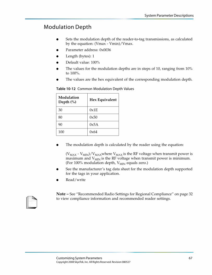
System Parameter Descriptions
Modulation Depth
● Sets the modulation depth of the reader-to-tag transmissions, as calculated by the equation: (Vmax - Vmin)/Vmax.
● Parameter address: 0x0036
● Length (bytes): 1
● Default value: 100%
● The values for the modulation depths are in steps of 10, ranging from 10% to 100%.
● The values are the hex equivalent of the corresponding modulation depth.
Table 10-12 Common Modulation Depth Values
Modulation Depth (%) Hex Equivalent
30 0x1E
80 0x50
90 0x5A
100 0x64
● The modulation depth is calculated by the reader using the equation: (VMAX - VMIN)/VMAXwhere VMAX is the RF voltage when transmit power is maximum and VMIN is the RF voltage when transmit power is minimum. (For 100% modulation depth, VMIN equals zero.)
● See the manufacturer’s tag data sheet for the modulation depth supported for the tags in your application.
● Read/write
L o r e m ip s u m d o lo r s it a me t, c o n s e c te tu e rlo b o r tis p u lv in a r ma g n a . Mo r b i q u is
fe r m e n tu m. In s o d a le s fe u g ia t s e m. S e d u t p e d e . N a m te mp u s . Ma e c e n a s r u tr u mC u r a b itu r n u n c . A e n e a n s c e le r is q u e
S u s p e n d is s e e r a t. Ma u r is u t c uv e s tib u lu m s e m. V iv a mu s e t, v e l le c tu s v ita e
U t o r c i r is u s , c o n v a llis e t, S u s p e n d is s e s u s c ip it v u lp u ta te e lit.
e tr a e n im. S u s p e n d is s e e le me n tu m. S e d e n im lo r e m, s u s c ip it q u is , v e s tib u lu m
in , s u s c ip it n o n , a n te . L o r e m ip s u m d o lo r s it a me t, c o n s e c te tu e r
h a b ita s s e p la te a d ic tu ms t.
S u s p e n d is s e s u s c ip it v u lp u ta te e lit.
. S e d
c o n s e c te tu e r r is u s .
lu c tu s imp e r d ie t.
p r e tiu m c o n d ime n tu m.
Note – See ‘‘Recommended Radio Settings for Regional Compliance’’ on page 32 to view compliance information and recommended reader settings.
Customizing System Parameters 67Copyright 2008 SkyeTek, Inc. All Rights Reserved. Revision 080527
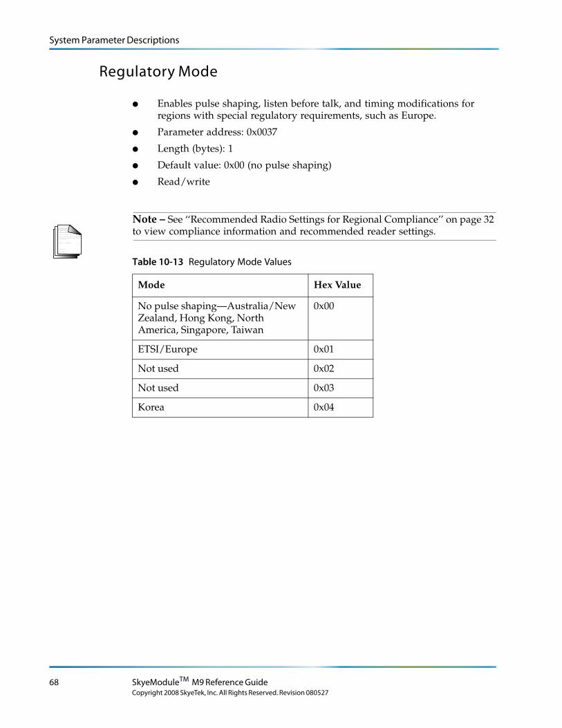
System Parameter Descriptions
Regulatory Mode
● Enables pulse shaping, listen before talk, and timing modifications for regions with special regulatory requirements, such as Europe.
● Parameter address: 0x0037
● Length (bytes): 1
● Default value: 0x00 (no pulse shaping)
● Read/write
L o r e m ip s u m d o lo r s it a me t, c o n s e c te tu e rlo b o r tis p u lv in a r ma g n a . Mo r b i q u is
fe r m e n tu m. In s o d a le s fe u g ia t s e m. S e d u t p e d e . N a m te mp u s . Ma e c e n a s r u tr u mC u r a b itu r n u n c . A e n e a n s c e le r is q u e
S u s p e n d is s e e r a t. Ma u r is u t c uv e s tib u lu m s e m. V iv a mu s e t, v e l le c tu s v ita e
U t o r c i r is u s , c o n v a llis e t, S u s p e n d is s e s u s c ip it v u lp u ta te e lit.
e tr a e n im. S u s p e n d is s e e le me n tu m. S e d e n im lo r e m, s u s c ip it q u is , v e s tib u lu m
in , s u s c ip it n o n , a n te . L o r e m ip s u m d o lo r s it a me t, c o n s e c te tu e r
h a b ita s s e p la te a d ic tu ms t.
S u s p e n d is s e s u s c ip it v u lp u ta te e lit.
. S e d
c o n s e c te tu e r r is u s .
lu c tu s imp e r d ie t.
p r e tiu m c o n d ime n tu m.
Note – See ‘‘Recommended Radio Settings for Regional Compliance’’ on page 32 to view compliance information and recommended reader settings.
Table 10-13 Regulatory Mode Values
Mode Hex Value
No pulse shaping—Australia/New Zealand, Hong Kong, North America, Singapore, Taiwan
0x00
ETSI/Europe 0x01
Not used 0x02
Not used 0x03
Korea 0x04
68 SkyeModuleTM M9 Reference Guide
Copyright 2008 SkyeTek, Inc. All Rights Reserved. Revision 080527
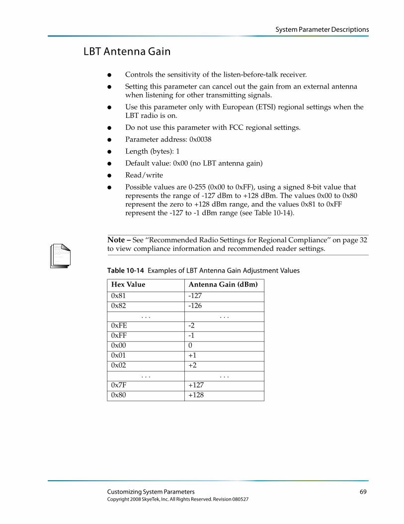
System Parameter Descriptions
LBT Antenna Gain
● Controls the sensitivity of the listen-before-talk receiver.
● Setting this parameter can cancel out the gain from an external antenna when listening for other transmitting signals.
● Use this parameter only with European (ETSI) regional settings when the LBT radio is on.
● Do not use this parameter with FCC regional settings.
● Parameter address: 0x0038
● Length (bytes): 1
● Default value: 0x00 (no LBT antenna gain)
● Read/write
● Possible values are 0-255 (0x00 to 0xFF), using a signed 8-bit value that represents the range of -127 dBm to +128 dBm. The values 0x00 to 0x80 represent the zero to +128 dBm range, and the values 0x81 to 0xFF represent the -127 to -1 dBm range (see Table 10-14).
L o r e m ip s u m d o lo r s it a me t, c o n s e c te tu e rlo b o r tis p u lv in a r ma g n a . Mo r b i q u is
fe r m e n tu m. In s o d a le s fe u g ia t s e m. S e d u t p e d e . N a m te mp u s . Ma e c e n a s r u tr u mC u r a b itu r n u n c . A e n e a n s c e le r is q u e
S u s p e n d is s e e r a t. Ma u r is u t c uv e s tib u lu m s e m. V iv a mu s e t, v e l le c tu s v ita e
U t o r c i r is u s , c o n v a llis e t, S u s p e n d is s e s u s c ip it v u lp u ta te e lit.
e tr a e n im. S u s p e n d is s e e le me n tu m. S e d e n im lo r e m, s u s c ip it q u is , v e s tib u lu m
in , s u s c ip it n o n , a n te . L o r e m ip s u m d o lo r s it a me t, c o n s e c te tu e r
h a b ita s s e p la te a d ic tu ms t.
S u s p e n d is s e s u s c ip it v u lp u ta te e lit.
. S e d
c o n s e c te tu e r r is u s .
lu c tu s imp e r d ie t.
p r e tiu m c o n d ime n tu m.
Note – See ‘‘Recommended Radio Settings for Regional Compliance’’ on page 32 to view compliance information and recommended reader settings.
Table 10-14 Examples of LBT Antenna Gain Adjustment Values
Hex Value Antenna Gain (dBm)
0x81 -1270x82 -126
. . . . . .0xFE -20xFF -10x00 00x01 +10x02 +2
. . . . . .0x7F +1270x80 +128
Customizing System Parameters 69Copyright 2008 SkyeTek, Inc. All Rights Reserved. Revision 080527

System Parameter Descriptions
70 SkyeModuleTM M9 Reference Guide
Copyright 2008 SkyeTek, Inc. All Rights Reserved. Revision 080527
Appendix A
Troubleshooting
This appendix describes how to diagnose and fix common problems that you may encounter.
Firmware Updates
Firmware updates may require that you temporarily limit the SkyeModule M9 to a baud rate to 38,400. For more information on how to set or reset the baud rate, see ‘‘Host Interface Baud Rate’’ on page 59.
Visual Indicators
The SkyeModule M9 has three LEDs: red, amber, and green.
● When lit, the red LED indicates the M9 has power. This LED is always on while the M9 is connected to a valid voltage source.
● When lit, the green LED indicates that the M9 achieved a frequency lock. This LED is usually on if the frequency of operation is within the valid range. (See the RF specifications in ‘‘Electrical Specifications’’ on page 121 for more information.) If this LED is off, the M9 will not function until the problem is resolved.
● The GPIO 3 pin connection controls LED D502, which toggles when a successful tag command occurs.
Reset Button
If you are using the SkyeModule M9 with a SkyeTek host interface board, you can restart the reader by pressing the reset button on the top of the host interface board and holding it down for a few seconds. (The button is labeled SW1 RESET.)
71
Copyright 2008 SkyeTek, Inc. All Rights Reserved. Revision 080527

Troubleshooting
Additional Information
See the SkyeTek Support Portal for additional troubleshooting information.
72 SkyeModuleTM M9 Reference Guide
Copyright 2008 SkyeTek, Inc. All Rights Reserved. Revision 080527
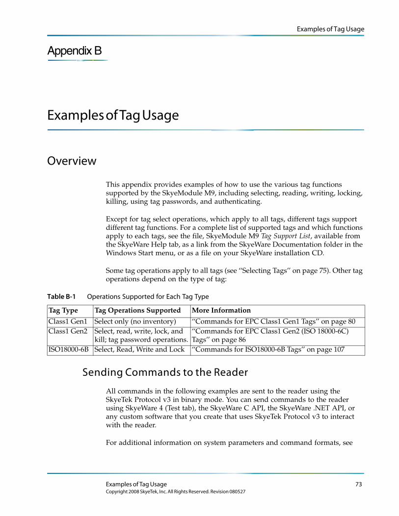
Examples of Tag Usage
Appendix B
Examples of Tag Usage
Overview
This appendix provides examples of how to use the various tag functions supported by the SkyeModule M9, including selecting, reading, writing, locking, killing, using tag passwords, and authenticating.
Except for tag select operations, which apply to all tags, different tags support different tag functions. For a complete list of supported tags and which functions apply to each tags, see the file, SkyeModule M9 Tag Support List, available from the SkyeWare Help tab, as a link from the SkyeWare Documentation folder in the Windows Start menu, or as a file on your SkyeWare installation CD.
Some tag operations apply to all tags (see ‘‘Selecting Tags’’ on page 75). Other tag operations depend on the type of tag:
Table B-1 Operations Supported for Each Tag Type
Tag Type Tag Operations Supported More Information
Class1 Gen1 Select only (no inventory) ‘‘Commands for EPC Class1 Gen1 Tags’’ on page 80Class1 Gen2 Select, read, write, lock, and
kill; tag password operations.‘‘Commands for EPC Class1 Gen2 (ISO 18000-6C) Tags’’ on page 86
ISO18000-6B Select, Read, Write and Lock ‘‘Commands for ISO18000-6B Tags’’ on page 107
Sending Commands to the Reader
All commands in the following examples are sent to the reader using the SkyeTek Protocol v3 in binary mode. You can send commands to the reader using SkyeWare 4 (Test tab), the SkyeWare C API, the SkyeWare .NET API, or any custom software that you create that uses SkyeTek Protocol v3 to interact with the reader.
For additional information on system parameters and command formats, see
Examples of Tag Usage 73Copyright 2008 SkyeTek, Inc. All Rights Reserved. Revision 080527
Examples of Tag Usage
● Chapter 10, ‘‘Customizing System Parameters’’ on page 51
● SkyeTek Protocol v3 Reference Guide
● SkyeTek Protocol v3 Examples
● Appendix C, ‘‘Using DESFire Commands’’ on page 109 for commands specific to DESFire tags.
L o r e m ip s u m d o lo r s it a me t, c o n s e c te tu e rlo b o r tis p u lv in a r ma g n a . Mo r b i q u is
fe r m e n tu m. In s o d a le s fe u g ia t s e m. S e d u t p e d e . N a m te mp u s . Ma e c e n a s r u tr u mC u r a b itu r n u n c . A e n e a n s c e le r is q u e
S u s p e n d is s e e r a t. Ma u r is u t c uv e s tib u lu m s e m. V iv a mu s e t, v e l le c tu s v ita e
U t o r c i r is u s , c o n v a llis e t, S u s p e n d is s e s u s c ip it v u lp u ta te e lit.
e tr a e n im. S u s p e n d is s e e le me n tu m. S e d e n im lo r e m, s u s c ip it q u is , v e s tib u lu m
in , s u s c ip it n o n , a n te . L o r e m ip s u m d o lo r s it a me t, c o n s e c te tu e r
h a b ita s s e p la te a d ic tu ms t.
S u s p e n d is s e s u s c ip it v u lp u ta te e lit.
. S e d
c o n s e c te tu e r r is u s .
lu c tu s imp e r d ie t.
p r e tiu m c o n d ime n tu m.
Note – If you set the tag type to Auto-Detect, the reader automatically includes the tag type in its response when a tag is successfully detected.
Setting Up RF Regional Compliance
See ‘‘Recommended Radio Settings for Regional Compliance’’ on page 32 to view compliance information and recommended reader settings. For additional information on system parameters and command formats, see ‘‘Customizing System Parameters’’ on page 51.
Summary of Tag Functions
Using SkyeTek Protocol v3 commands, you can control the following tag functions with the SkyeModule M9:
● Select – Queries tags in the field of the reader for their unique IDs or EPCs.
● Read – Reads data from the nonvolatile memory of a tag.
● Write – Writes data to the nonvolatile memory in a block or group of blocks on a tag specified.
● Lock – Locks a nonvolatile memory block specified of the tag specified.
● Get Lock Status – Gets the lock status of the block specified.
● Kill – Permanently disables a tag.
● Tag Password – Writes a password to a tag or presents the tag with a password for operations that require password authentication.
74 SkyeModuleTM M9 Reference Guide
Copyright 2008 SkyeTek, Inc. All Rights Reserved. Revision 080527
Examples of Tag Usage
Selecting Tags
Selection operations apply to all tag types.
The Select Tag command returns the Unique ID or the EPC code of a tag in the field of the reader. The UID or EPC can later be used to address a specific tag when executing tag-specific commands. The reader has several modes for selecting tags:
Autodetect Mode: Reader automatically selects any recognized tag placed in the detection field.
Loop Mode: Reader detects tags in a continuous loop until loop mode is turned off or until another command stops the loop. (This function works only when the Reader ID system parameter is set to FFFFFFFF. See ‘‘Selecting Any Supported Tag Continuously’’ on page 77 for more information.)
Inventory Mode: Reader selects all tags in the detection field until a tag is placed in the field or until the inventory times out. This lets you read a “stack” of tags instead of reading and selecting each type of tag individually.
L o r e m ip s u m d o lo r s it a me t, c o n s e c te tu e rlo b o r tis p u lv in a r ma g n a . Mo r b i q u is
fe r m e n tu m. In s o d a le s fe u g ia t s e m. S e d u t p e d e . N a m te mp u s . Ma e c e n a s r u tr u mC u r a b itu r n u n c . A e n e a n s c e le r is q u e
S u s p e n d is s e e r a t. Ma u r is u t c uv e s tib u lu m s e m. V iv a mu s e t, v e l le c tu s v ita e
U t o r c i r is u s , c o n v a llis e t, S u s p e n d is s e s u s c ip it v u lp u ta te e lit.
e tr a e n im. S u s p e n d is s e e le me n tu m. S e d e n im lo r e m, s u s c ip it q u is , v e s tib u lu m
in , s u s c ip it n o n , a n te . L o r e m ip s u m d o lo r s it a me t, c o n s e c te tu e r
h a b ita s s e p la te a d ic tu ms t.
S u s p e n d is s e s u s c ip it v u lp u ta te e lit.
. S e d
c o n s e c te tu e r r is u s .
lu c tu s imp e r d ie t.
p r e tiu m c o n d ime n tu m.
Note – The format of the Select Tag response is the same for Loop and Inventory Modes.
Using Auto-Detect Functionality
When you set the tag type to Auto-Detect, the reader determines the tag type of any tags in the field and include this information in the response if any tags are successfully detected. There are several levels of Auto-Detect functionality:
● Auto-Detect – The reader scans for any tag type that it supports and reports back the UID (or EPC) and tag type of the first tag it detects.
● Air Interface Auto-Detect – The reader scans for the first tag with the specified air interface and reports back its UID (or EPC) and the tag type it detected. Tag types of different air interfaces are reported.
● Manufacturer and Air Interface Specific Auto-Detect – The reader scans for the first tag with the specified manufacturer and air interface and reports back its UID (or EPC) and tag type. Tag types of different manufacturers with the same air interface are not reported.
● Tag Type Specific Select – The reader scans for the first tag of the specified tag type and report its UID (or EPC). The tag type is not reported, nor are any other tag types in the field.
Examples of Tag Usage 75Copyright 2008 SkyeTek, Inc. All Rights Reserved. Revision 080527
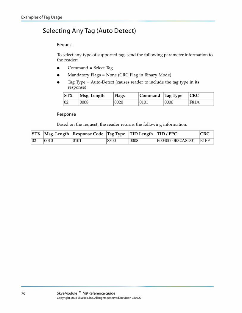
Examples of Tag Usage
Selecting Any Tag (Auto Detect)
Request
To select any type of supported tag, send the following parameter information to the reader:
● Command = Select Tag
● Mandatory Flags = None (CRC Flag in Binary Mode)
● Tag Type = Auto-Detect (causes reader to include the tag type in its response)
STX Msg. Length Flags Command Tag Type CRC
02 0008 0020 0101 0000 F81A
Response
Based on the request, the reader returns the following information:
STX Msg. Length Response Code Tag Type TID Length TID / EPC CRC
02 0010 0101 8300 0008 E0040000B32A8D01 E1FF
76 SkyeModuleTM M9 Reference Guide
Copyright 2008 SkyeTek, Inc. All Rights Reserved. Revision 080527
Examples of Tag Usage
Selecting Any Supported Tag Continuously
Sending the following command sets up continuous monitoring of whatever supported tag type is detected. The first time you send this command, it places the reader into loop mode, which sends a response whenever a tag enters the detection field or when there is a change in the field. Sending any command to the reader turns off loop mode.
L o r e m ip s u m d o lo r s it a me t, c o n s e c te tu e rlo b o r tis p u lv in a r ma g n a . Mo r b i q u is
fe r m e n tu m. In s o d a le s fe u g ia t s e m. S e d u t p e d e . N a m te mp u s . Ma e c e n a s r u tr u mC u r a b itu r n u n c . A e n e a n s c e le r is q u e
S u s p e n d is s e e r a t. Ma u r is u t c uv e s tib u lu m s e m. V iv a mu s e t, v e l le c tu s v ita e
U t o r c i r is u s , c o n v a llis e t, S u s p e n d is s e s u s c ip it v u lp u ta te e lit.
e tr a e n im. S u s p e n d is s e e le me n tu m. S e d e n im lo r e m, s u s c ip it q u is , v e s tib u lu m
in , s u s c ip it n o n , a n te . L o r e m ip s u m d o lo r s it a me t, c o n s e c te tu e r
h a b ita s s e p la te a d ic tu ms t.
S u s p e n d is s e s u s c ip it v u lp u ta te e lit.
. S e d
c o n s e c te tu e r r is u s .
lu c tu s imp e r d ie t.
p r e tiu m c o n d ime n tu m.
Note – Loop mode is designed for demonstrations and read range testing. Therefore, loop mode only works when the reader ID is set to the factory default of FFFFFFFF. In typical working applications, readers with unique reader ID's are grouped together on one port or host; they do not need to remain in loop mode, because the host system usually switches between different readers quickly and frequently.
L o r e m ip s u m d o lo r s it a me t, c o n s e c te tu e rlo b o r tis p u lv in a r ma g n a . Mo r b i q u is
fe r m e n tu m. In s o d a le s fe u g ia t s e m. S e d u t p e d e . N a m te mp u s . Ma e c e n a s r u tr u mC u r a b itu r n u n c . A e n e a n s c e le r is q u e
S u s p e n d is s e e r a t. Ma u r is u t c uv e s tib u lu m s e m. V iv a mu s e t, v e l le c tu s v ita e
U t o r c i r is u s , c o n v a llis e t, S u s p e n d is s e s u s c ip it v u lp u ta te e lit.
e tr a e n im. S u s p e n d is s e e le me n tu m. S e d e n im lo r e m, s u s c ip it q u is , v e s tib u lu m
in , s u s c ip it n o n , a n te . L o r e m ip s u m d o lo r s it a me t, c o n s e c te tu e r
h a b ita s s e p la te a d ic tu ms t.
S u s p e n d is s e s u s c ip it v u lp u ta te e lit.
. S e d
c o n s e c te tu e r r is u s .
lu c tu s imp e r d ie t.
p r e tiu m c o n d ime n tu m.
Note – When using Loop mode, place only one tag at a time in the reader’s detection field. Refer to the SkyeTek Development Kit User Guide for more information about using Loop mode to test read range and about anti-collision capabilities for multiple tags.
Request
To set up continuous monitoring, send the following parameter information to the reader:
● Command = Select Tag
● Mandatory Flags = Loop Flag (CRC Flag in Binary Mode)
● Tag Type = Auto-Detect
STX Msg. Length Flags Command Tag Type CRC
02 0008 0021 0101 0000 F35E
Response
Start of Loop Mode
The reader returns the following information when it starts loop mode:
STX Msg. Length Response Code CRC
02 0004 01C1 AD3C
Examples of Tag Usage 77Copyright 2008 SkyeTek, Inc. All Rights Reserved. Revision 080527
Examples of Tag Usage
Reading Tags
The following table shows sample responses from the reader while in loop mode as the user places various tags one-at-a-time in the detection field. There can be any number of reads.
STX Msg. Length Response Code Tag Type TID Length TID / EPC CRC02 0010 0101 8300 0008 E0040000B32A8D01 E1FF02 0010 0101 8300 0008 E0040000B32A8D01 E1FF02 0010 0101 8300 0008 E0040000B32A8D01 E1FF
.
.
.
02 0014 0101 8200 000C 334455660000000000000000 421E02 0014 0101 8200 000C 334455660000000000000000 421E02 0014 0101 8200 000C 334455660000000000000000 421E
End Loop Mode
The reader exits loop mode when you send another command.
STX Msg. Len Response Code CRC
02 0004 81C1 21F0
78 SkyeModuleTM M9 Reference Guide
Copyright 2008 SkyeTek, Inc. All Rights Reserved. Revision 080527
Examples of Tag Usage
Selecting All Tags of Any Type (Inventory Mode)
Inventory mode permits reading of all tags in the detection field. This lets you read a “stack” of tags instead of having to read each type of tag individually. This mode gives you an easy way to test or demonstrate the reader’s anti-collision capabilities.
Request
To set up monitoring, send the following parameter information to the reader:
● Command = Select Tag
● Mandatory Flags = Inventory Flag (CRC Flag in Binary Mode)
● Tag Type = Auto-Detect
STX Msg. Len Flags Command Tag Type CRC
02 0008 0022 0101 0000 EE92
Response
The reader returns information for all tag types detected. At the end of the tag Inventory, the reader will send the Inventory Complete Response code (810F).
STX Msg. Length Response Code Tag Type TID Length TID / EPC CRC
02 0014 0101 8100 000C 000000000000610222103654 084F02 0014 0101 8200 000C 112233440707080809090A0A DF0B02 0014 0101 8200 000C A01A050821A142106A010802 C35402 0010 0101 8300 0008 E0040000989C6001 ABC302 0004 810F 0E82
Examples of Tag Usage 79Copyright 2008 SkyeTek, Inc. All Rights Reserved. Revision 080527
Examples of Tag Usage
Commands for EPC Class1 Gen1 Tags
This section discusses tag commands that specifically apply to EPC Class1 Gen1 tags. The commands for loop and inventory mode discussed in the section (‘‘Selecting Tags’’ on page 75) also apply to these tags.
Selecting Only EPC Class1 Gen1 Tags
Request
To detect only EPC Class1 Gen1 tags, send the following parameter information to the reader. (If you set the tag type to EPC Class1 Gen1 Auto-Detect, the reader includes the tag type in the response when a tag is successfully detected.)
● Command = Select Tag
● Mandatory Flags = None (CRC Flag in Binary Mode)
● Tag Type = EPC Class1 Gen1
STX Msg. Len Flags Command Tag Type CRC
02 0008 0020 0101 8100 6D0E
Response
The reader sends the following response:
STX Msg. Length Response Code Tag Type TID Length TID / EPC CRC
02 0014 0101 8100 000C 000000000000610222103654 084F
80 SkyeModuleTM M9 Reference Guide
Copyright 2008 SkyeTek, Inc. All Rights Reserved. Revision 080527
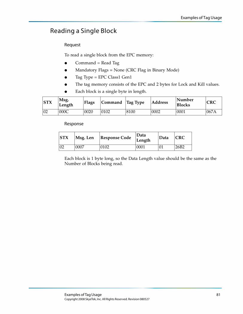
Examples of Tag Usage
Reading a Single Block
Request
To read a single block from the EPC memory:
● Command = Read Tag
● Mandatory Flags = None (CRC Flag in Binary Mode)
● Tag Type = EPC Class1 Gen1
● The tag memory consists of the EPC and 2 bytes for Lock and Kill values.
● Each block is a single byte in length.
STXMsg. Length Flags Command Tag Type Address
Number Blocks CRC
02 000C 0020 0102 8100 0002 0001 067A
Response
Each block is 1 byte long, so the Data Length value should be the same as the Number of Blocks being read.
STX Msg. Len Response Code Data Length
Data CRC
02 0007 0102 0001 01 26B2
Examples of Tag Usage 81Copyright 2008 SkyeTek, Inc. All Rights Reserved. Revision 080527
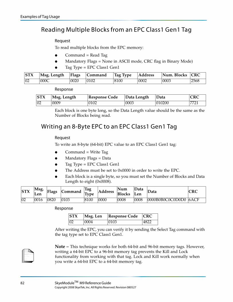
Examples of Tag Usage
Reading Multiple Blocks from an EPC Class1 Gen1 Tag
RequestTo read multiple blocks from the EPC memory:
● Command = Read Tag● Mandatory Flags = None in ASCII mode, CRC flag in Binary Mode)● Tag Type = EPC Class1 Gen1
STX Msg. Length Flags Command Tag Type Address Num. Blocks CRC02 000C 0020 0102 8100 0002 0003 2568
Response
Each block is one byte long, so the Data Length value should be the same as the Number of Blocks being read.
Writing an 8-Byte EPC to an EPC Class1 Gen1 Tag
RequestTo write an 8-byte (64-bit) EPC value to an EPC Class1 Gen1 tag:
● Command = Write Tag● Mandatory Flags = Data● Tag Type = EPC Class1 Gen1● The Address must be set to 0x0000 in order to write the EPC. ● Each block is a single byte, so you must set the Number of Blocks and Data
Length to eight (0x0008).
STXMsg. Len Flags Command
Tag Type Address
Num Blocks
Data Len Data CRC
02 0016 0820 0103 8100 0000 0008 0008 0000B0B0C0C0D0D0 6ACF
Response
After writing the EPC, you can verify it by sending the Select Tag command with the tag type set to EPC Class1 Gen1.
L o r e m ip s u m d o lo r s it a me t, c o n s e c te tu e rlo b o r tis p u lv in a r ma g n a . Mo r b i q u is
fe r m e n tu m. In s o d a le s fe u g ia t s e m. S e d u t p e d e . N a m te mp u s . Ma e c e n a s r u tr u mC u r a b itu r n u n c . A e n e a n s c e le r is q u e
S u s p e n d is s e e r a t. Ma u r is u t c uv e s tib u lu m s e m. V iv a mu s e t, v e l le c tu s v ita e
U t o r c i r is u s , c o n v a llis e t, S u s p e n d is s e s u s c ip it v u lp u ta te e lit.
e tr a e n im. S u s p e n d is s e e le me n tu m. S e d e n im lo r e m, s u s c ip it q u is , v e s tib u lu m
in , s u s c ip it n o n , a n te . L o r e m ip s u m d o lo r s it a me t, c o n s e c te tu e r
h a b ita s s e p la te a d ic tu ms t.
S u s p e n d is s e s u s c ip it v u lp u ta te e lit.
. S e d
c o n s e c te tu e r r is u s .
lu c tu s imp e r d ie t.
p r e tiu m c o n d ime n tu m.
Note – This technique works for both 64-bit and 96-bit memory tags. However, writing a 64-bit EPC to a 96-bit memory tag prevents the Kill and Lock functionality from working with that tag. Lock and Kill work normally when you write a 64-bit EPC to a 64-bit memory tag.
STX Msg. Length Response Code Data Length Data CRC02 0009 0102 0003 010200 7721
STX Msg. Len Response Code CRC02 0004 0103 4822
82 SkyeModuleTM M9 Reference Guide
Copyright 2008 SkyeTek, Inc. All Rights Reserved. Revision 080527
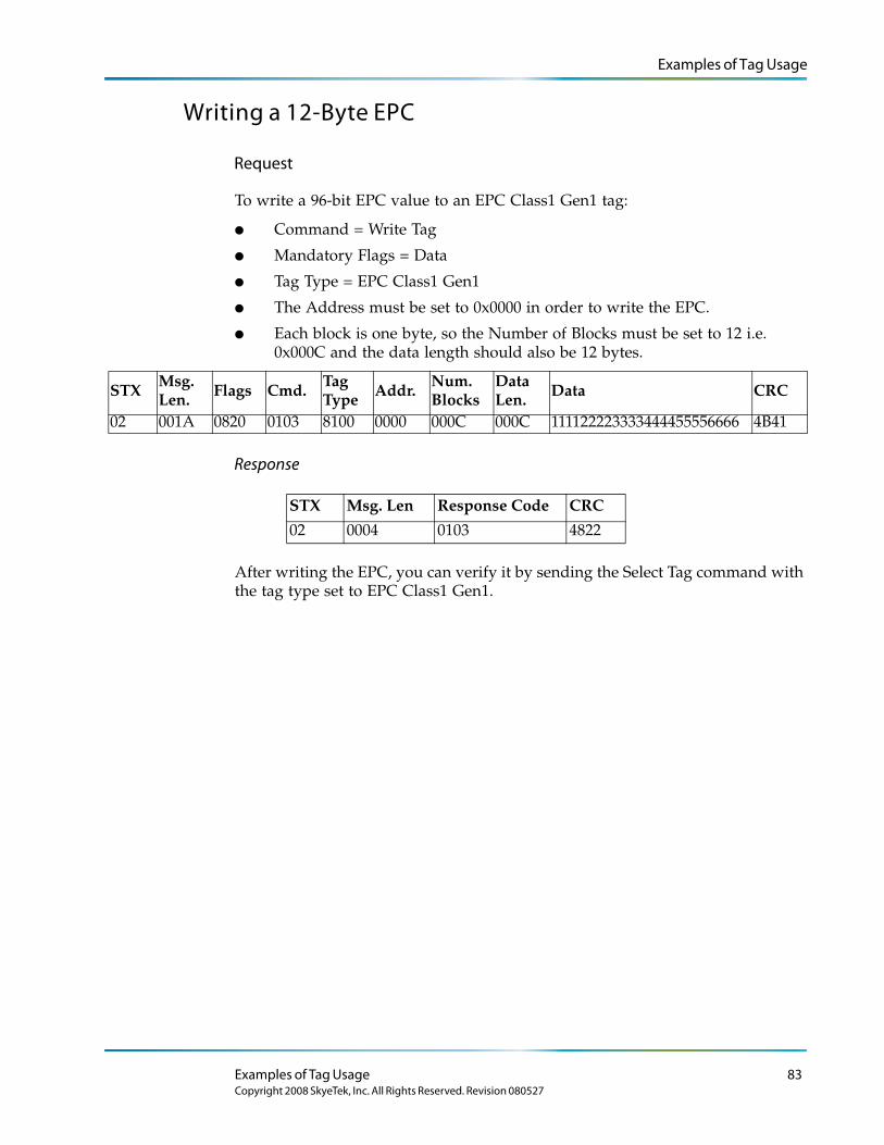
Examples of Tag Usage
Writing a 12-Byte EPC
Request
To write a 96-bit EPC value to an EPC Class1 Gen1 tag:
● Command = Write Tag
● Mandatory Flags = Data
● Tag Type = EPC Class1 Gen1
● The Address must be set to 0x0000 in order to write the EPC.
● Each block is one byte, so the Number of Blocks must be set to 12 i.e. 0x000C and the data length should also be 12 bytes.
STXMsg. Len. Flags Cmd.
Tag Type Addr.
Num. Blocks
Data Len. Data CRC
02 001A 0820 0103 8100 0000 000C 000C 111122223333444455556666 4B41
Response
After writing the EPC, you can verify it by sending the Select Tag command with the tag type set to EPC Class1 Gen1.
STX Msg. Len Response Code CRC
02 0004 0103 4822
Examples of Tag Usage 83Copyright 2008 SkyeTek, Inc. All Rights Reserved. Revision 080527
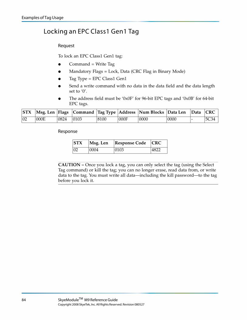
Examples of Tag Usage
Locking an EPC Class1 Gen1 Tag
Request
To lock an EPC Class1 Gen1 tag:
● Command = Write Tag
● Mandatory Flags = Lock, Data (CRC Flag in Binary Mode)
● Tag Type = EPC Class1 Gen1
● Send a write command with no data in the data field and the data length set to ‘0’.
● The address field must be ‘0x0F’ for 96-bit EPC tags and ‘0x0B’ for 64-bit EPC tags.
STX Msg. Len Flags Command Tag Type Address Num Blocks Data Len Data CRC
02 000E 0824 0103 8100 000F 0000 0000 - 5C34
Response
CAUTION – Once you lock a tag, you can only select the tag (using the Select Tag command) or kill the tag; you can no longer erase, read data from, or write data to the tag. You must write all data—including the kill password—to the tag before you lock it.
STX Msg. Len Response Code CRC
02 0004 0103 4822
84 SkyeModuleTM M9 Reference Guide
Copyright 2008 SkyeTek, Inc. All Rights Reserved. Revision 080527
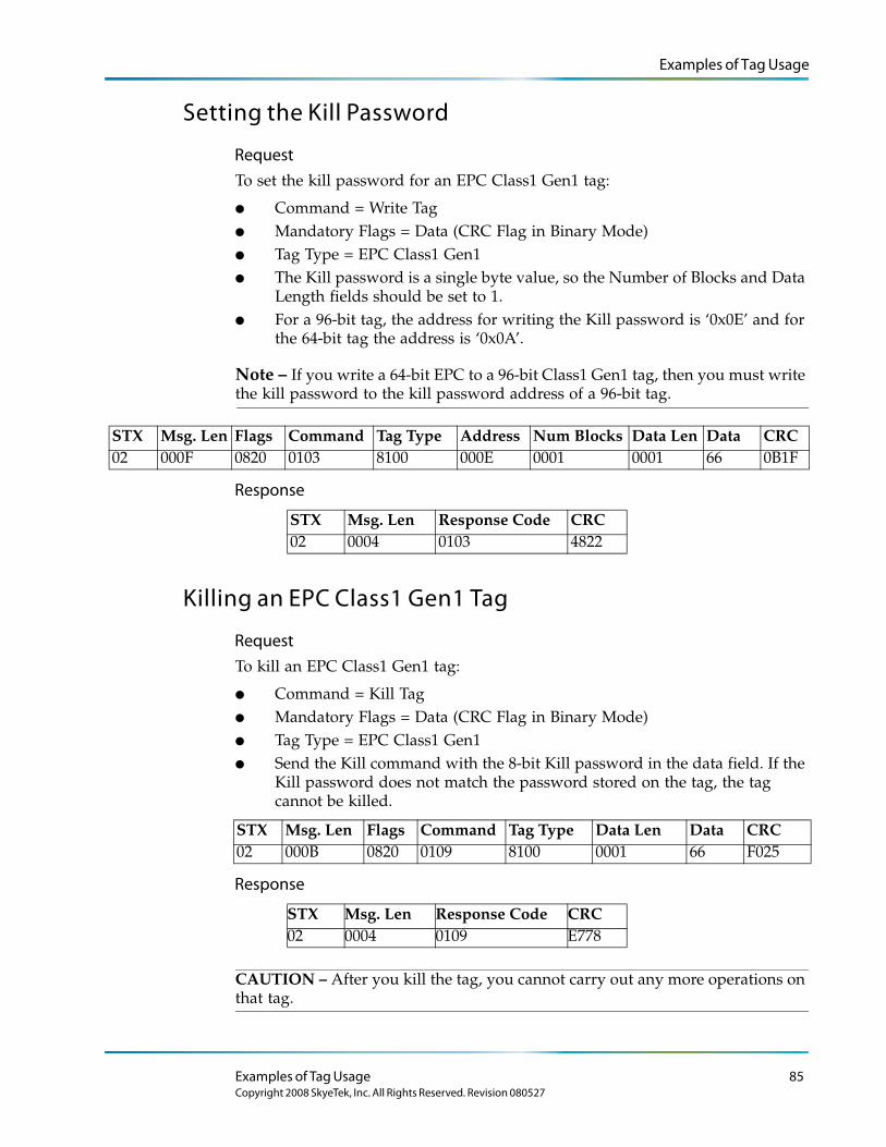
Examples of Tag Usage
Setting the Kill Password
RequestTo set the kill password for an EPC Class1 Gen1 tag:
● Command = Write Tag● Mandatory Flags = Data (CRC Flag in Binary Mode)● Tag Type = EPC Class1 Gen1● The Kill password is a single byte value, so the Number of Blocks and Data
Length fields should be set to 1. ● For a 96-bit tag, the address for writing the Kill password is ‘0x0E’ and for
the 64-bit tag the address is ‘0x0A’.
Note – If you write a 64-bit EPC to a 96-bit Class1 Gen1 tag, then you must write the kill password to the kill password address of a 96-bit tag.
STX Msg. Len Flags Command Tag Type Address Num Blocks Data Len Data CRC02 000F 0820 0103 8100 000E 0001 0001 66 0B1F
Response
Killing an EPC Class1 Gen1 Tag
RequestTo kill an EPC Class1 Gen1 tag:
● Command = Kill Tag● Mandatory Flags = Data (CRC Flag in Binary Mode)● Tag Type = EPC Class1 Gen1● Send the Kill command with the 8-bit Kill password in the data field. If the
Kill password does not match the password stored on the tag, the tag cannot be killed.
STX Msg. Len Flags Command Tag Type Data Len Data CRC02 000B 0820 0109 8100 0001 66 F025
Response
CAUTION – After you kill the tag, you cannot carry out any more operations on that tag.
STX Msg. Len Response Code CRC02 0004 0103 4822
STX Msg. Len Response Code CRC02 0004 0109 E778
Examples of Tag Usage 85Copyright 2008 SkyeTek, Inc. All Rights Reserved. Revision 080527
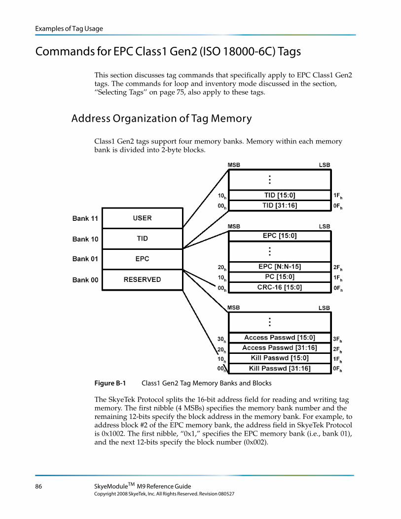
Examples of Tag Usage
Commands for EPC Class1 Gen2 (ISO 18000-6C) Tags
This section discusses tag commands that specifically apply to EPC Class1 Gen2 tags. The commands for loop and inventory mode discussed in the section, ‘‘Selecting Tags’’ on page 75, also apply to these tags.
Address Organization of Tag Memory
Class1 Gen2 tags support four memory banks. Memory within each memory bank is divided into 2-byte blocks.
Figure B-1 Class1 Gen2 Tag Memory Banks and Blocks
The SkyeTek Protocol splits the 16-bit address field for reading and writing tag memory. The first nibble (4 MSBs) specifies the memory bank number and the remaining 12-bits specify the block address in the memory bank. For example, to address block #2 of the EPC memory bank, the address field in SkyeTek Protocol is 0x1002. The first nibble, “0x1,” specifies the EPC memory bank (i.e., bank 01), and the next 12-bits specify the block number (0x002).
86 SkyeModuleTM M9 Reference Guide
Copyright 2008 SkyeTek, Inc. All Rights Reserved. Revision 080527
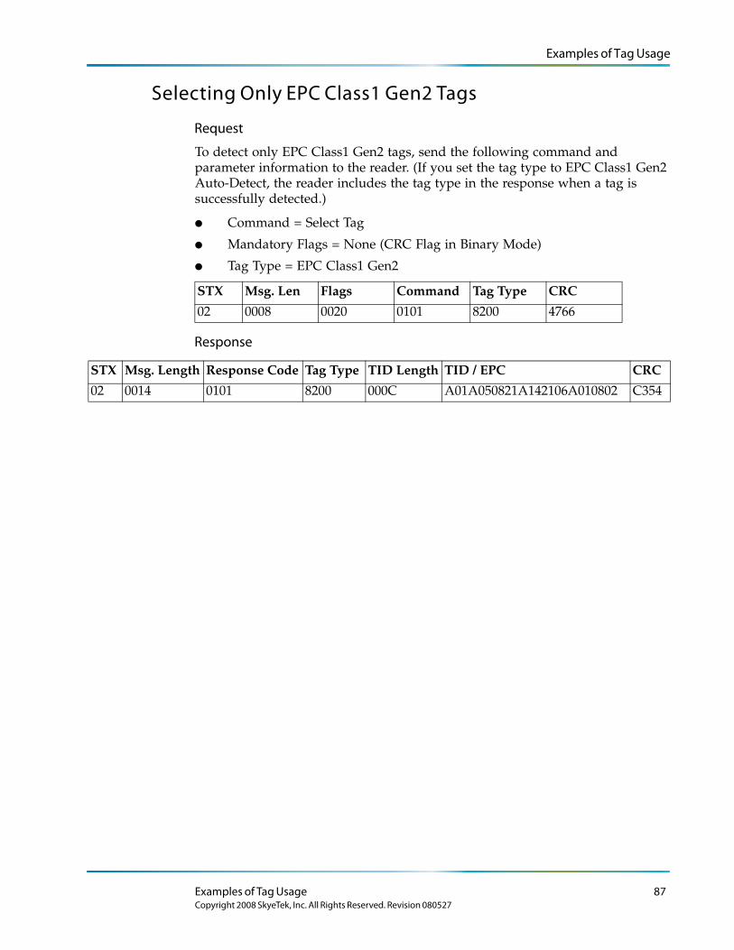
Examples of Tag Usage
Selecting Only EPC Class1 Gen2 Tags
Request
To detect only EPC Class1 Gen2 tags, send the following command and parameter information to the reader. (If you set the tag type to EPC Class1 Gen2 Auto-Detect, the reader includes the tag type in the response when a tag is successfully detected.)
● Command = Select Tag
● Mandatory Flags = None (CRC Flag in Binary Mode)
● Tag Type = EPC Class1 Gen2
STX Msg. Len Flags Command Tag Type CRC
02 0008 0020 0101 8200 4766
Response
STX Msg. Length Response Code Tag Type TID Length TID / EPC CRC
02 0014 0101 8200 000C A01A050821A142106A010802 C354
Examples of Tag Usage 87Copyright 2008 SkyeTek, Inc. All Rights Reserved. Revision 080527
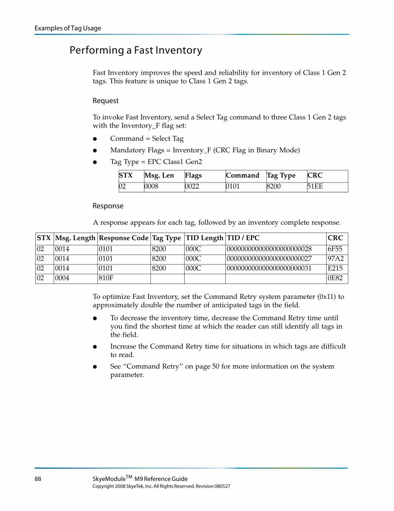
Examples of Tag Usage
Performing a Fast Inventory
Fast Inventory improves the speed and reliability for inventory of Class 1 Gen 2 tags. This feature is unique to Class 1 Gen 2 tags.
Request
To invoke Fast Inventory, send a Select Tag command to three Class 1 Gen 2 tags with the Inventory_F flag set:
● Command = Select Tag
● Mandatory Flags = Inventory_F (CRC Flag in Binary Mode)
● Tag Type = EPC Class1 Gen2
STX Msg. Len Flags Command Tag Type CRC
02 0008 0022 0101 8200 51EE
Response
A response appears for each tag, followed by an inventory complete response.
STX Msg. Length Response Code Tag Type TID Length TID / EPC CRC
02 0014 0101 8200 000C 000000000000000000000028 6F5502 0014 0101 8200 000C 000000000000000000000027 97A202 0014 0101 8200 000C 000000000000000000000031 E21502 0004 810F 0E82
To optimize Fast Inventory, set the Command Retry system parameter (0x11) to approximately double the number of anticipated tags in the field.
● To decrease the inventory time, decrease the Command Retry time until you find the shortest time at which the reader can still identify all tags in the field.
● Increase the Command Retry time for situations in which tags are difficult to read.
● See ‘‘Command Retry’’ on page 50 for more information on the system parameter.
88 SkyeModuleTM M9 Reference Guide
Copyright 2008 SkyeTek, Inc. All Rights Reserved. Revision 080527
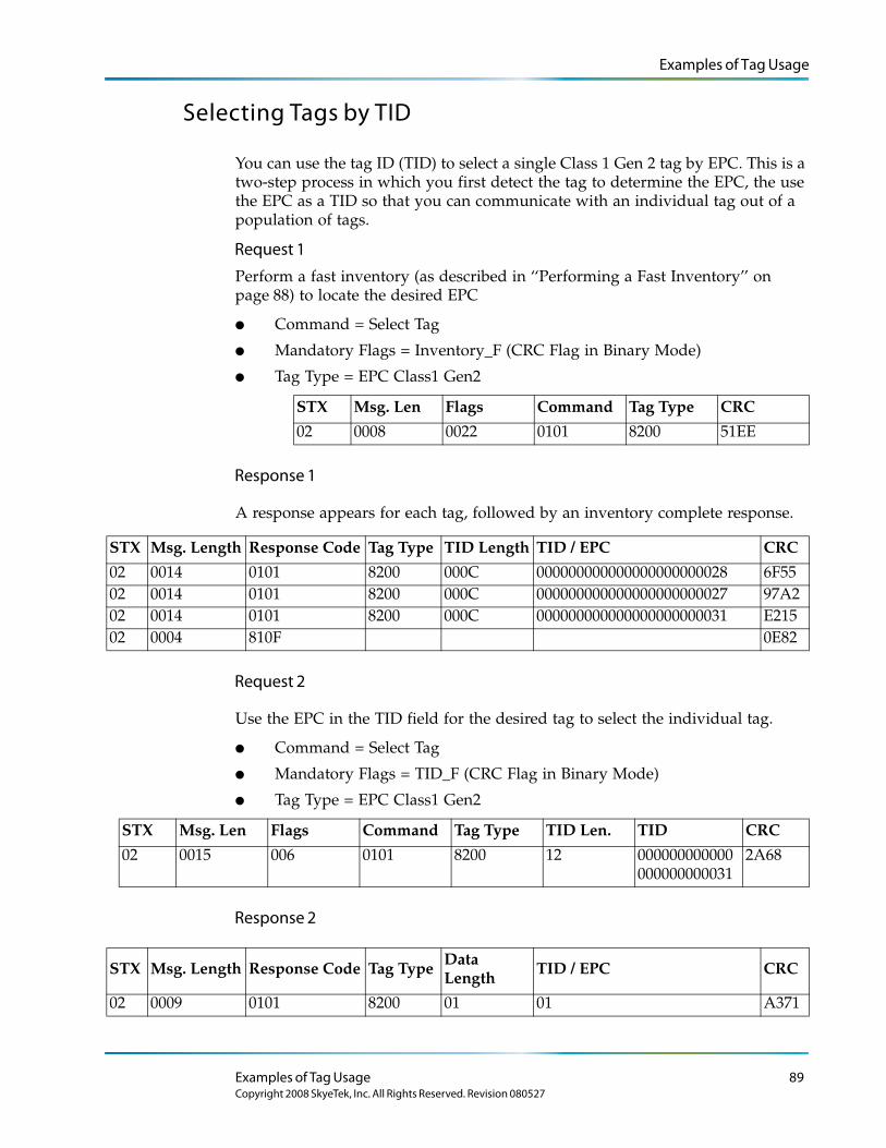
Examples of Tag Usage
Selecting Tags by TID
You can use the tag ID (TID) to select a single Class 1 Gen 2 tag by EPC. This is a two-step process in which you first detect the tag to determine the EPC, the use the EPC as a TID so that you can communicate with an individual tag out of a population of tags.
Request 1
Perform a fast inventory (as described in ‘‘Performing a Fast Inventory’’ on page 88) to locate the desired EPC
● Command = Select Tag
● Mandatory Flags = Inventory_F (CRC Flag in Binary Mode)
● Tag Type = EPC Class1 Gen2
STX Msg. Len Flags Command Tag Type CRC
02 0008 0022 0101 8200 51EE
Response 1
A response appears for each tag, followed by an inventory complete response.
STX Msg. Length Response Code Tag Type TID Length TID / EPC CRC
02 0014 0101 8200 000C 000000000000000000000028 6F5502 0014 0101 8200 000C 000000000000000000000027 97A202 0014 0101 8200 000C 000000000000000000000031 E21502 0004 810F 0E82
Request 2
Use the EPC in the TID field for the desired tag to select the individual tag.
● Command = Select Tag
● Mandatory Flags = TID_F (CRC Flag in Binary Mode)
● Tag Type = EPC Class1 Gen2
STX Msg. Len Flags Command Tag Type TID Len. TID CRC
02 0015 006 0101 8200 12 000000000000000000000031
2A68
Response 2
STX Msg. Length Response Code Tag Type Data Length
TID / EPC CRC
02 0009 0101 8200 01 01 A371
Examples of Tag Usage 89Copyright 2008 SkyeTek, Inc. All Rights Reserved. Revision 080527
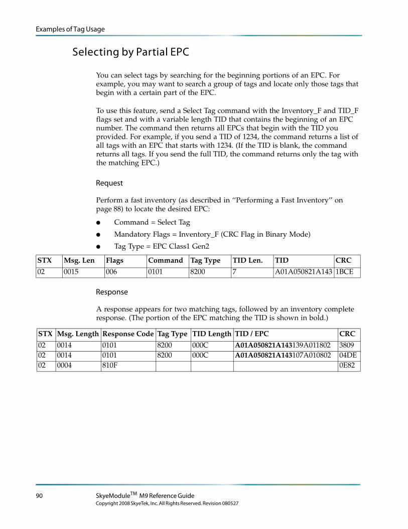
Examples of Tag Usage
Selecting by Partial EPC
You can select tags by searching for the beginning portions of an EPC. For example, you may want to search a group of tags and locate only those tags that begin with a certain part of the EPC.
To use this feature, send a Select Tag command with the Inventory_F and TID_F flags set and with a variable length TID that contains the beginning of an EPC number. The command then returns all EPCs that begin with the TID you provided. For example, if you send a TID of 1234, the command returns a list of all tags with an EPC that starts with 1234. (If the TID is blank, the command returns all tags. If you send the full TID, the command returns only the tag with the matching EPC.)
Request
Perform a fast inventory (as described in ‘‘Performing a Fast Inventory’’ on page 88) to locate the desired EPC:
● Command = Select Tag
● Mandatory Flags = Inventory_F (CRC Flag in Binary Mode)
● Tag Type = EPC Class1 Gen2
STX Msg. Len Flags Command Tag Type TID Len. TID CRC
02 0015 006 0101 8200 7 A01A050821A143 1BCE
Response
A response appears for two matching tags, followed by an inventory complete response. (The portion of the EPC matching the TID is shown in bold.)
STX Msg. Length Response Code Tag Type TID Length TID / EPC CRC
02 0014 0101 8200 000C A01A050821A143139A011802 380902 0014 0101 8200 000C A01A050821A143107A010802 04DE02 0004 810F 0E82
90 SkyeModuleTM M9 Reference Guide
Copyright 2008 SkyeTek, Inc. All Rights Reserved. Revision 080527
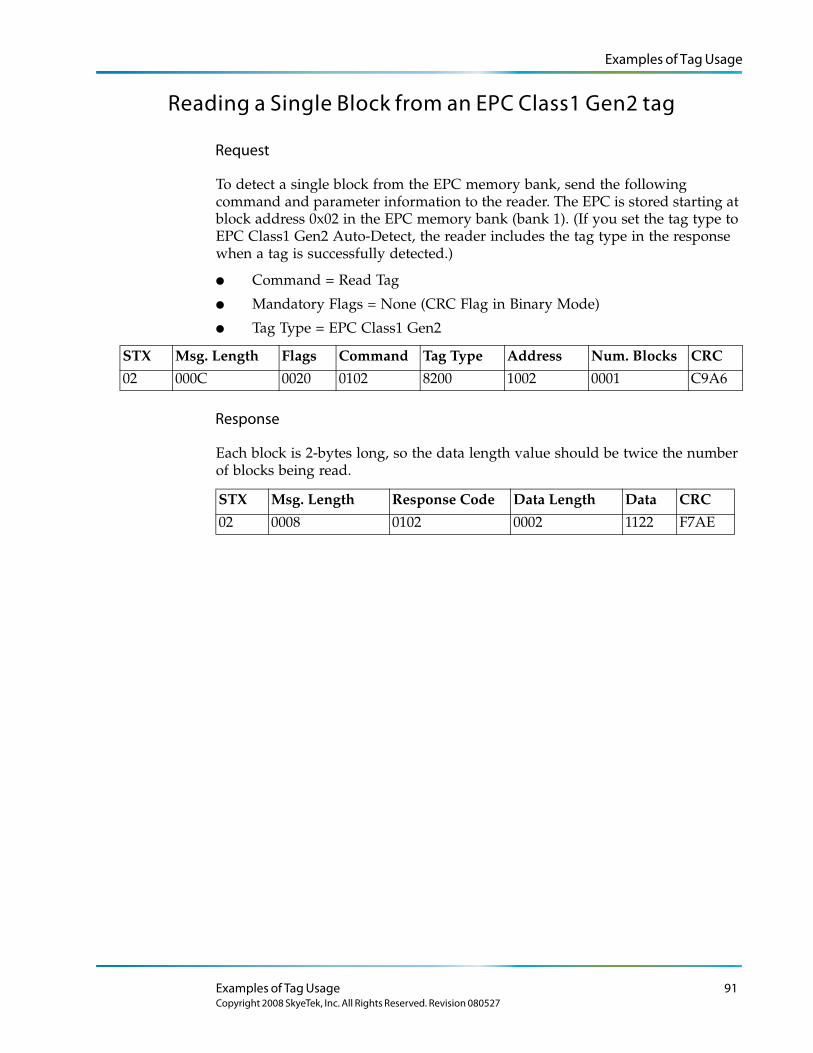
Examples of Tag Usage
Reading a Single Block from an EPC Class1 Gen2 tag
Request
To detect a single block from the EPC memory bank, send the following command and parameter information to the reader. The EPC is stored starting at block address 0x02 in the EPC memory bank (bank 1). (If you set the tag type to EPC Class1 Gen2 Auto-Detect, the reader includes the tag type in the response when a tag is successfully detected.)
● Command = Read Tag
● Mandatory Flags = None (CRC Flag in Binary Mode)
● Tag Type = EPC Class1 Gen2
STX Msg. Length Flags Command Tag Type Address Num. Blocks CRC
02 000C 0020 0102 8200 1002 0001 C9A6
Response
Each block is 2-bytes long, so the data length value should be twice the number of blocks being read.
STX Msg. Length Response Code Data Length Data CRC
02 0008 0102 0002 1122 F7AE
Examples of Tag Usage 91Copyright 2008 SkyeTek, Inc. All Rights Reserved. Revision 080527
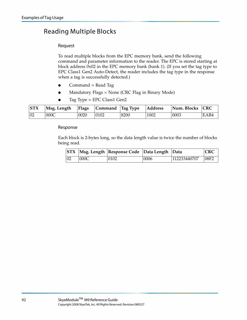
Examples of Tag Usage
Reading Multiple Blocks
Request
To read multiple blocks from the EPC memory bank, send the following command and parameter information to the reader. The EPC is stored starting at block address 0x02 in the EPC memory bank (bank 1). (If you set the tag type to EPC Class1 Gen2 Auto-Detect, the reader includes the tag type in the response when a tag is successfully detected.)
● Command = Read Tag
● Mandatory Flags = None (CRC Flag in Binary Mode)
● Tag Type = EPC Class1 Gen2
STX Msg. Length Flags Command Tag Type Address Num. Blocks CRC
02 000C 0020 0102 8200 1002 0003 EAB4
Response
Each block is 2-bytes long, so the data length value is twice the number of blocks being read.
STX Msg. Length Response Code Data Length Data CRC
02 000C 0102 0006 112233440707 08F2
92 SkyeModuleTM M9 Reference Guide
Copyright 2008 SkyeTek, Inc. All Rights Reserved. Revision 080527
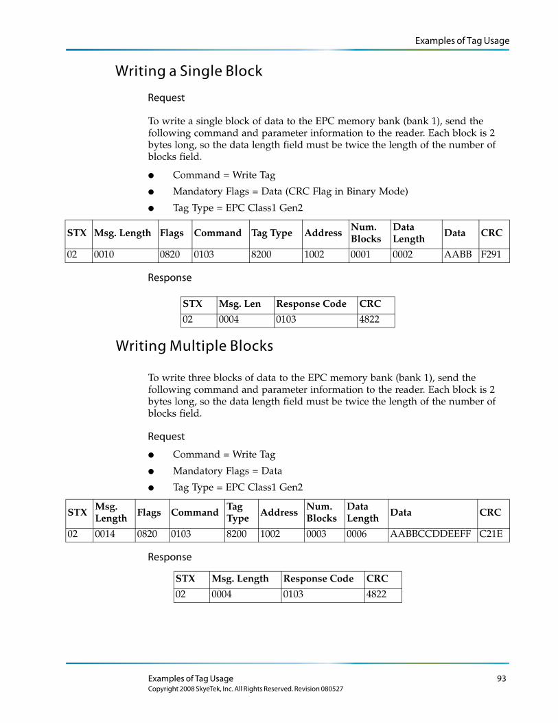
Examples of Tag Usage
Writing a Single Block
Request
To write a single block of data to the EPC memory bank (bank 1), send the following command and parameter information to the reader. Each block is 2 bytes long, so the data length field must be twice the length of the number of blocks field.
● Command = Write Tag
● Mandatory Flags = Data (CRC Flag in Binary Mode)
● Tag Type = EPC Class1 Gen2
STX Msg. Length Flags Command Tag Type AddressNum. Blocks
Data Length Data CRC
02 0010 0820 0103 8200 1002 0001 0002 AABB F291
Response
Writing Multiple Blocks
To write three blocks of data to the EPC memory bank (bank 1), send the following command and parameter information to the reader. Each block is 2 bytes long, so the data length field must be twice the length of the number of blocks field.
Request
● Command = Write Tag
● Mandatory Flags = Data
● Tag Type = EPC Class1 Gen2
STX Msg. Length Flags Command Tag
Type Address Num. Blocks
Data Length Data CRC
02 0014 0820 0103 8200 1002 0003 0006 AABBCCDDEEFF C21E
Response
STX Msg. Len Response Code CRC
02 0004 0103 4822
STX Msg. Length Response Code CRC
02 0004 0103 4822
Examples of Tag Usage 93Copyright 2008 SkyeTek, Inc. All Rights Reserved. Revision 080527

Examples of Tag Usage
Writing a 12-byte EPC
To write a 12-byte (96-bit) EPC value to the EPC memory bank (bank 1), send the following command and parameter information to the reader.
Request
● Command = Write Tag
● Mandatory Flags = Data
● Tag Type = EPC Class1 Gen2
STX Msg. Length
Flags Command Tag Type
Address Num. Blocks
Data Length
Data CRC
02 001A 0820 0103 8200 1002 0006 000C 101112131415161718191A1B
753D
Response
After writing the EPC to the EPC bank, make sure that the PC value (i.e., block address 0x01) is written with the correct value. The PC value determines the length of the EPC and a value of 0x3000 creates an EPC of 12-bytes (96-bits). To verify the EPC, the send the Select Tag command with the tag type set to EPC Class1 Gen2.
STX Msg. Length Response Code CRC
02 0004 0103 4822
94 SkyeModuleTM M9 Reference Guide
Copyright 2008 SkyeTek, Inc. All Rights Reserved. Revision 080527
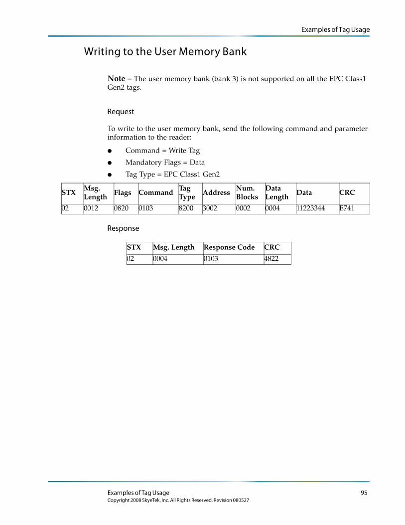
Examples of Tag Usage
Writing to the User Memory Bank
Note – The user memory bank (bank 3) is not supported on all the EPC Class1 Gen2 tags.
Request
To write to the user memory bank, send the following command and parameter information to the reader:
● Command = Write Tag
● Mandatory Flags = Data
● Tag Type = EPC Class1 Gen2
STX Msg. Length
Flags Command Tag Type
Address Num. Blocks
Data Length
Data CRC
02 0012 0820 0103 8200 3002 0002 0004 11223344 E741
Response
STX Msg. Length Response Code CRC
02 0004 0103 4822
Examples of Tag Usage 95Copyright 2008 SkyeTek, Inc. All Rights Reserved. Revision 080527
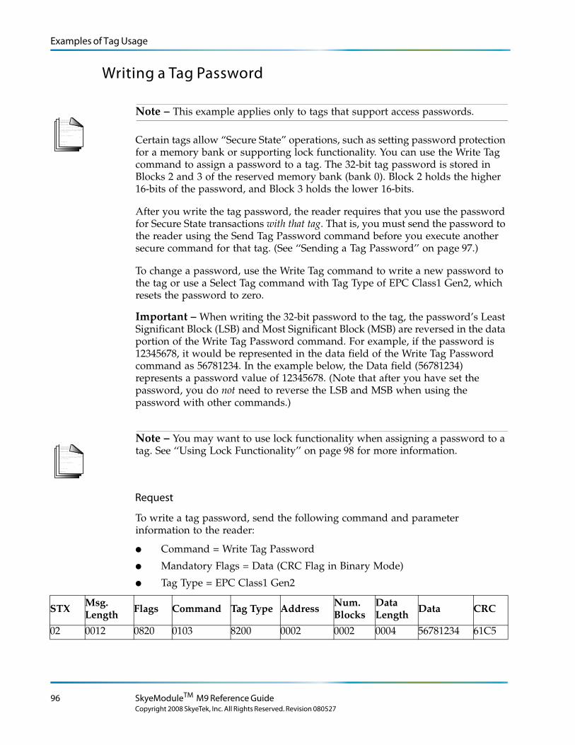
Examples of Tag Usage
Writing a Tag Password
L o r e m ip s u m d o lo r s it a me t, c o n s e c te tu e rlo b o r tis p u lv in a r ma g n a . Mo r b i q u is
fe r m e n tu m. In s o d a le s fe u g ia t s e m. S e d u t p e d e . N a m te mp u s . Ma e c e n a s r u tr u mC u r a b itu r n u n c . A e n e a n s c e le r is q u e
S u s p e n d is s e e r a t. Ma u r is u t c uv e s tib u lu m s e m. V iv a mu s e t, v e l le c tu s v ita e
U t o r c i r is u s , c o n v a llis e t, S u s p e n d is s e s u s c ip it v u lp u ta te e lit.
e tr a e n im. S u s p e n d is s e e le me n tu m. S e d e n im lo r e m, s u s c ip it q u is , v e s tib u lu m
in , s u s c ip it n o n , a n te . L o r e m ip s u m d o lo r s it a me t, c o n s e c te tu e r
h a b ita s s e p la te a d ic tu ms t.
S u s p e n d is s e s u s c ip it v u lp u ta te e lit.
. S e d
c o n s e c te tu e r r is u s .
lu c tu s imp e r d ie t.
p r e tiu m c o n d ime n tu m.
Note – This example applies only to tags that support access passwords.
Certain tags allow “Secure State” operations, such as setting password protection for a memory bank or supporting lock functionality. You can use the Write Tag command to assign a password to a tag. The 32-bit tag password is stored in Blocks 2 and 3 of the reserved memory bank (bank 0). Block 2 holds the higher 16-bits of the password, and Block 3 holds the lower 16-bits.
After you write the tag password, the reader requires that you use the password for Secure State transactions with that tag. That is, you must send the password to the reader using the Send Tag Password command before you execute another secure command for that tag. (See ‘‘Sending a Tag Password’’ on page 97.)
To change a password, use the Write Tag command to write a new password to the tag or use a Select Tag command with Tag Type of EPC Class1 Gen2, which resets the password to zero.
Important – When writing the 32-bit password to the tag, the password’s Least Significant Block (LSB) and Most Significant Block (MSB) are reversed in the data portion of the Write Tag Password command. For example, if the password is 12345678, it would be represented in the data field of the Write Tag Password command as 56781234. In the example below, the Data field (56781234) represents a password value of 12345678. (Note that after you have set the password, you do not need to reverse the LSB and MSB when using the password with other commands.)
L o r e m ip s u m d o lo r s it a me t, c o n s e c te tu e rlo b o r tis p u lv in a r ma g n a . Mo r b i q u is
fe r m e n tu m. In s o d a le s fe u g ia t s e m. S e d u t p e d e . N a m te mp u s . Ma e c e n a s r u tr u mC u r a b itu r n u n c . A e n e a n s c e le r is q u e
S u s p e n d is s e e r a t. Ma u r is u t c uv e s tib u lu m s e m. V iv a mu s e t, v e l le c tu s v ita e
U t o r c i r is u s , c o n v a llis e t, S u s p e n d is s e s u s c ip it v u lp u ta te e lit.
e tr a e n im. S u s p e n d is s e e le me n tu m. S e d e n im lo r e m, s u s c ip it q u is , v e s tib u lu m
in , s u s c ip it n o n , a n te . L o r e m ip s u m d o lo r s it a me t, c o n s e c te tu e r
h a b ita s s e p la te a d ic tu ms t.
S u s p e n d is s e s u s c ip it v u lp u ta te e lit.
. S e d
c o n s e c te tu e r r is u s .
lu c tu s imp e r d ie t.
p r e tiu m c o n d ime n tu m.
Note – You may want to use lock functionality when assigning a password to a tag. See ‘‘Using Lock Functionality’’ on page 98 for more information.
Request
To write a tag password, send the following command and parameter information to the reader:
● Command = Write Tag Password
● Mandatory Flags = Data (CRC Flag in Binary Mode)
● Tag Type = EPC Class1 Gen2
STX Msg. Length
Flags Command Tag Type Address Num. Blocks
Data Length
Data CRC
02 0012 0820 0103 8200 0002 0002 0004 56781234 61C5
96 SkyeModuleTM M9 Reference Guide
Copyright 2008 SkyeTek, Inc. All Rights Reserved. Revision 080527
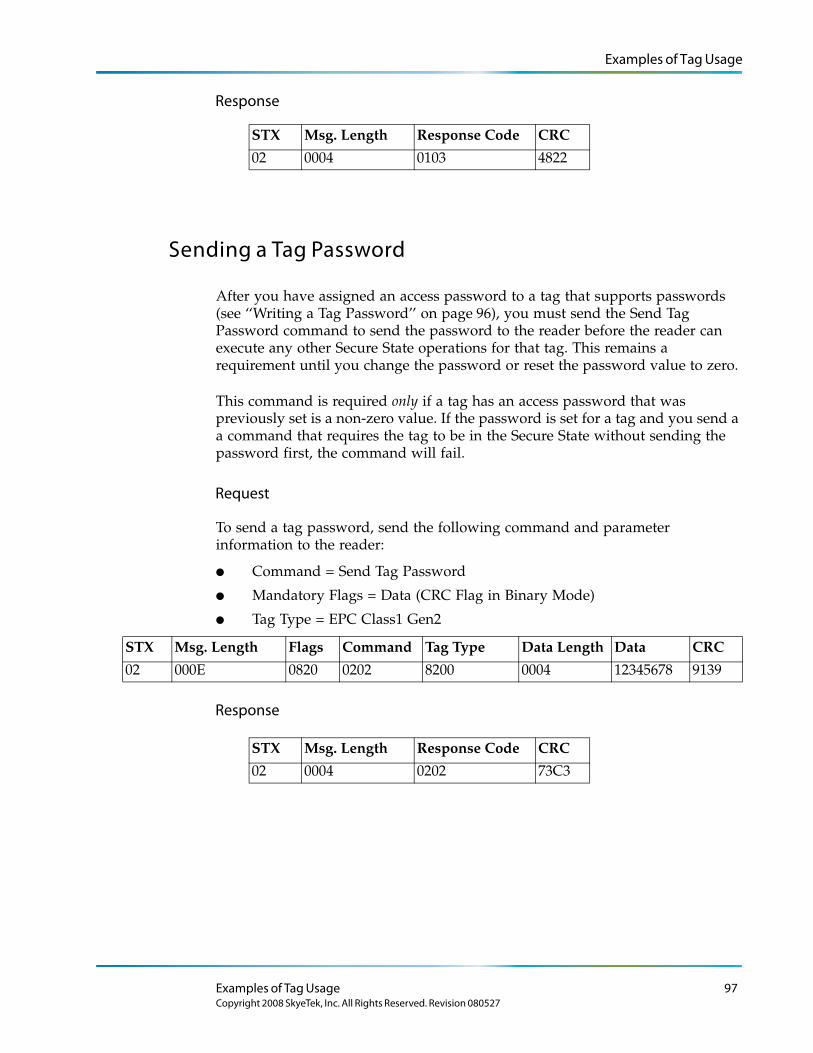
Examples of Tag Usage
Response
Sending a Tag Password
After you have assigned an access password to a tag that supports passwords (see ‘‘Writing a Tag Password’’ on page 96), you must send the Send Tag Password command to send the password to the reader before the reader can execute any other Secure State operations for that tag. This remains a requirement until you change the password or reset the password value to zero.
This command is required only if a tag has an access password that was previously set is a non-zero value. If the password is set for a tag and you send a a command that requires the tag to be in the Secure State without sending the password first, the command will fail.
Request
To send a tag password, send the following command and parameter information to the reader:
● Command = Send Tag Password
● Mandatory Flags = Data (CRC Flag in Binary Mode)
● Tag Type = EPC Class1 Gen2
STX Msg. Length Flags Command Tag Type Data Length Data CRC
02 000E 0820 0202 8200 0004 12345678 9139
Response
STX Msg. Length Response Code CRC
02 0004 0103 4822
STX Msg. Length Response Code CRC
02 0004 0202 73C3
Examples of Tag Usage 97Copyright 2008 SkyeTek, Inc. All Rights Reserved. Revision 080527
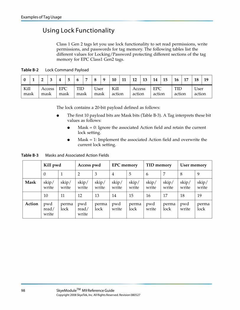
Examples of Tag Usage
Using Lock Functionality
Class 1 Gen 2 tags let you use lock functionality to set read permissions, write permissions, and passwords for tag memory. The following tables list the different values for Locking/Password protecting different sections of the tag memory for EPC Class1 Gen2 tags.
Table B-2 Lock Command Payload
0 1 2 3 4 5 6 7 8 9 10 11 12 13 14 15 16 17 18 19
Kill mask
Access mask
EPC mask
TID mask
User mask
Kill action
Access action
EPC action
TID action
User action
The lock contains a 20-bit payload defined as follows:
● The first 10 payload bits are Mask bits (Table B-3). A Tag interprets these bit values as follows:
● Mask = 0: Ignore the associated Action field and retain the current lock setting.
● Mask = 1: Implement the associated Action field and overwrite the current lock setting.
Table B-3 Masks and Associated Action Fields
Kill pwd Access pwd EPC memory TID memory User memory
0 1 2 3 4 5 6 7 8 9
Mask skip/write
skip/write
skip/write
skip/write
skip/write
skip/write
skip/write
skip/write
skip/write
skip/write
10 11 12 13 14 15 16 17 18 19
Action pwd read/write
permalock
pwd read/write
permalock
pwd write
permalock
pwd write
permalock
pwd write
permalock
98 SkyeModuleTM M9 Reference Guide
Copyright 2008 SkyeTek, Inc. All Rights Reserved. Revision 080527
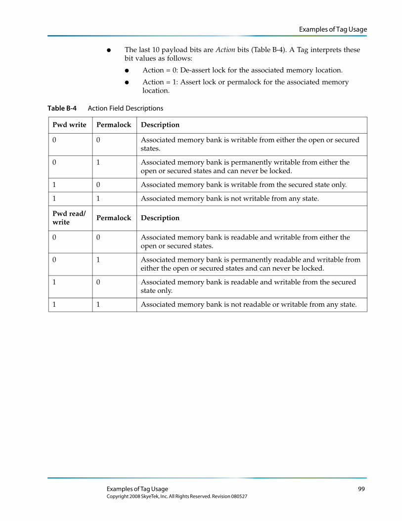
Examples of Tag Usage
● The last 10 payload bits are Action bits (Table B-4). A Tag interprets these bit values as follows:
● Action = 0: De-assert lock for the associated memory location.
● Action = 1: Assert lock or permalock for the associated memory location.
Table B-4 Action Field Descriptions
Pwd write Permalock Description
0 0 Associated memory bank is writable from either the open or secured states.
0 1 Associated memory bank is permanently writable from either the open or secured states and can never be locked.
1 0 Associated memory bank is writable from the secured state only.
1 1 Associated memory bank is not writable from any state.
Pwd read/ write Permalock Description
0 0 Associated memory bank is readable and writable from either the open or secured states.
0 1 Associated memory bank is permanently readable and writable from either the open or secured states and can never be locked.
1 0 Associated memory bank is readable and writable from the secured state only.
1 1 Associated memory bank is not readable or writable from any state.
Examples of Tag Usage 99Copyright 2008 SkyeTek, Inc. All Rights Reserved. Revision 080527
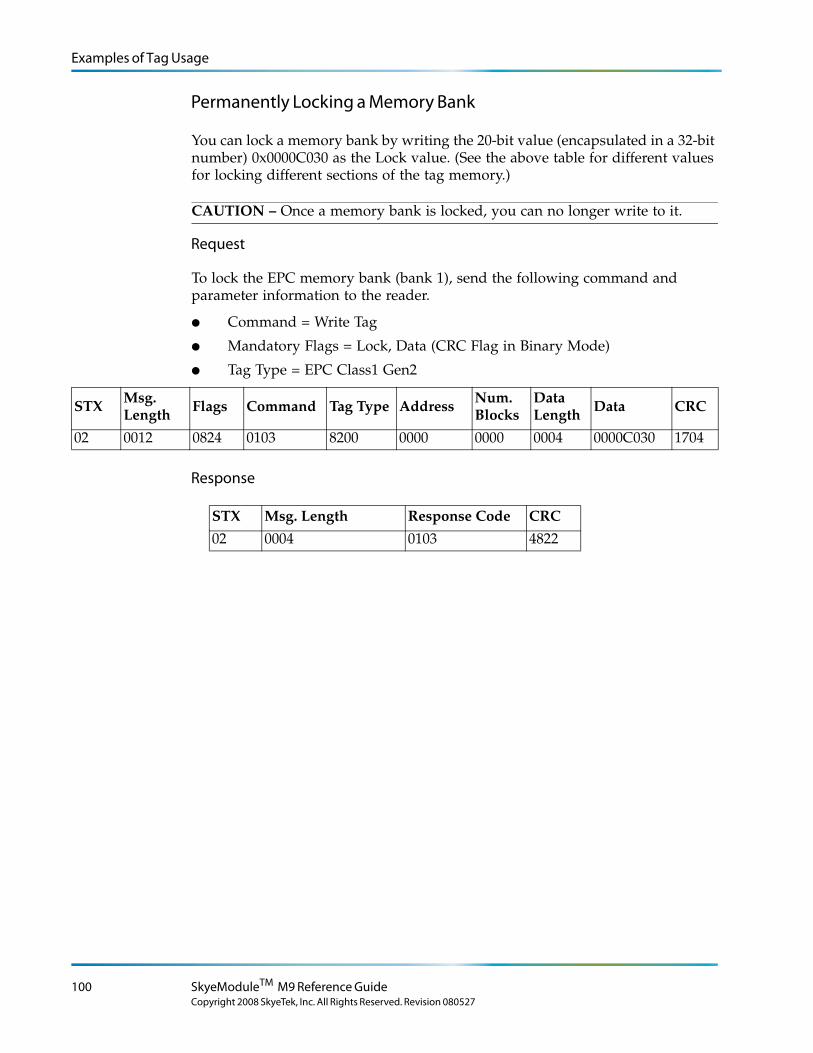
Examples of Tag Usage
Permanently Locking a Memory Bank
You can lock a memory bank by writing the 20-bit value (encapsulated in a 32-bit number) 0x0000C030 as the Lock value. (See the above table for different values for locking different sections of the tag memory.)
CAUTION – Once a memory bank is locked, you can no longer write to it.
Request
To lock the EPC memory bank (bank 1), send the following command and parameter information to the reader.
● Command = Write Tag
● Mandatory Flags = Lock, Data (CRC Flag in Binary Mode)
● Tag Type = EPC Class1 Gen2
STX Msg. Length Flags Command Tag Type Address Num.
BlocksData Length Data CRC
02 0012 0824 0103 8200 0000 0000 0004 0000C030 1704
Response
STX Msg. Length Response Code CRC
02 0004 0103 4822
100 SkyeModuleTM M9 Reference Guide
Copyright 2008 SkyeTek, Inc. All Rights Reserved. Revision 080527
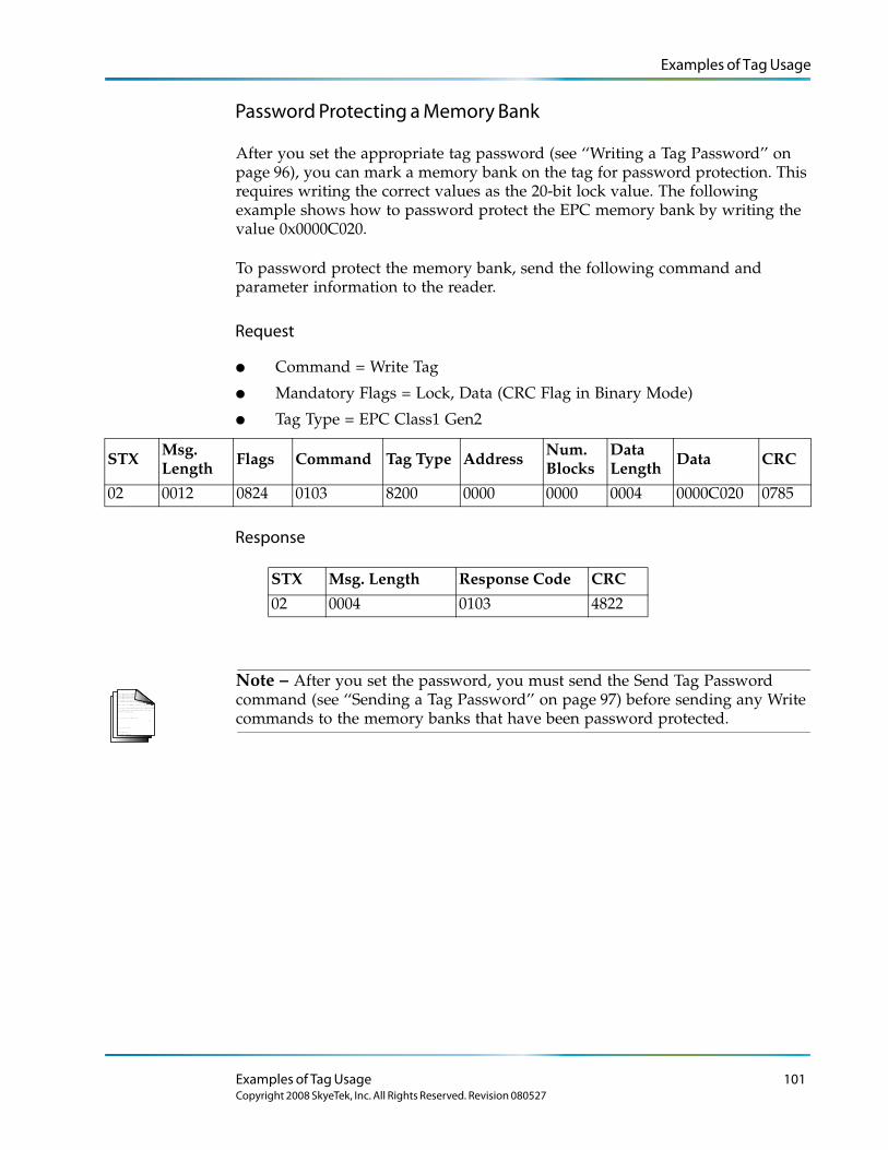
Examples of Tag Usage
Password Protecting a Memory Bank
After you set the appropriate tag password (see ‘‘Writing a Tag Password’’ on page 96), you can mark a memory bank on the tag for password protection. This requires writing the correct values as the 20-bit lock value. The following example shows how to password protect the EPC memory bank by writing the value 0x0000C020.
To password protect the memory bank, send the following command and parameter information to the reader.
Request
● Command = Write Tag
● Mandatory Flags = Lock, Data (CRC Flag in Binary Mode)
● Tag Type = EPC Class1 Gen2
STX Msg. Length
Flags Command Tag Type Address Num. Blocks
Data Length
Data CRC
02 0012 0824 0103 8200 0000 0000 0004 0000C020 0785
Response
L o r e m ip s u m d o lo r s it a me t, c o n s e c te tu e rlo b o r tis p u lv in a r ma g n a . Mo r b i q u is
fe r m e n tu m. In s o d a le s fe u g ia t s e m. S e d u t p e d e . N a m te mp u s . Ma e c e n a s r u tr u mC u r a b itu r n u n c . A e n e a n s c e le r is q u e
S u s p e n d is s e e r a t. Ma u r is u t c uv e s tib u lu m s e m. V iv a mu s e t, v e l le c tu s v ita e
U t o r c i r is u s , c o n v a llis e t, S u s p e n d is s e s u s c ip it v u lp u ta te e lit.
e tr a e n im. S u s p e n d is s e e le me n tu m. S e d e n im lo r e m, s u s c ip it q u is , v e s tib u lu m
in , s u s c ip it n o n , a n te . L o r e m ip s u m d o lo r s it a me t, c o n s e c te tu e r
h a b ita s s e p la te a d ic tu ms t.
S u s p e n d is s e s u s c ip it v u lp u ta te e lit.
. S e d
c o n s e c te tu e r r is u s .
lu c tu s imp e r d ie t.
p r e tiu m c o n d ime n tu m.
Note – After you set the password, you must send the Send Tag Password command (see ‘‘Sending a Tag Password’’ on page 97) before sending any Write commands to the memory banks that have been password protected.
STX Msg. Length Response Code CRC
02 0004 0103 4822
Examples of Tag Usage 101Copyright 2008 SkyeTek, Inc. All Rights Reserved. Revision 080527
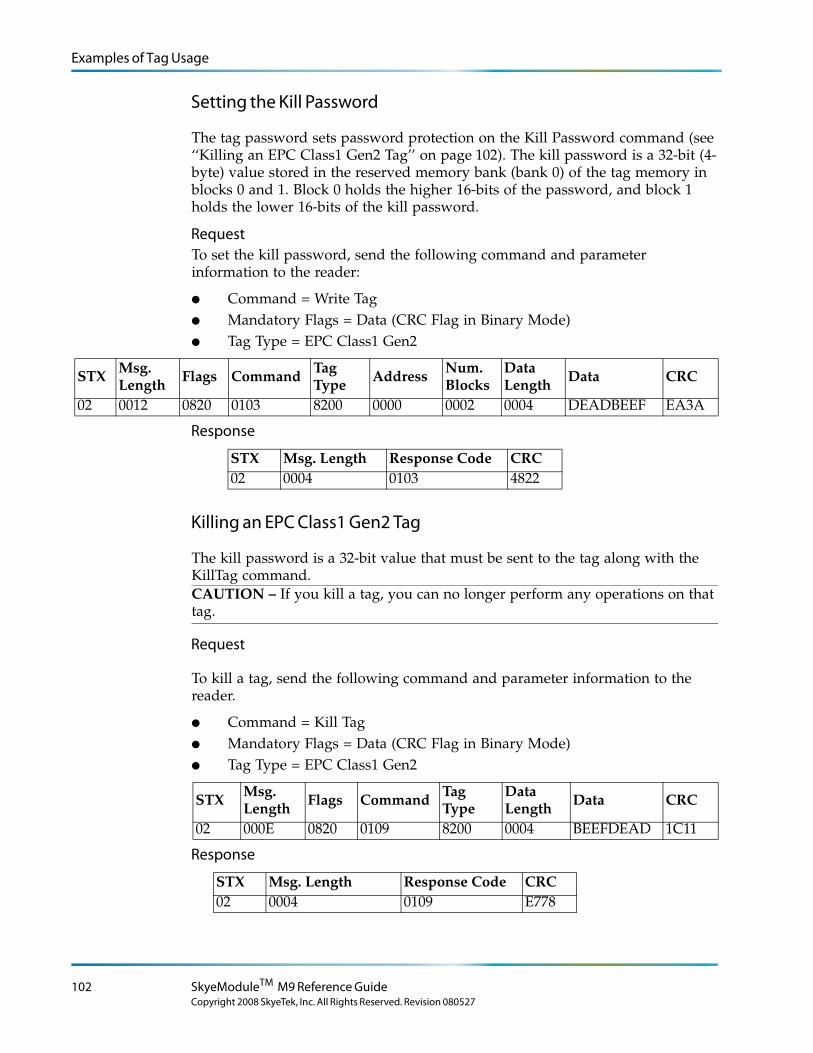
Examples of Tag Usage
Setting the Kill Password
The tag password sets password protection on the Kill Password command (see ‘‘Killing an EPC Class1 Gen2 Tag’’ on page 102). The kill password is a 32-bit (4-byte) value stored in the reserved memory bank (bank 0) of the tag memory in blocks 0 and 1. Block 0 holds the higher 16-bits of the password, and block 1 holds the lower 16-bits of the kill password.
RequestTo set the kill password, send the following command and parameter information to the reader:
● Command = Write Tag● Mandatory Flags = Data (CRC Flag in Binary Mode)● Tag Type = EPC Class1 Gen2
STX Msg. Length
Flags Command Tag Type
Address Num. Blocks
Data Length
Data CRC
02 0012 0820 0103 8200 0000 0002 0004 DEADBEEF EA3A
Response
Killing an EPC Class1 Gen2 Tag
The kill password is a 32-bit value that must be sent to the tag along with the KillTag command.CAUTION – If you kill a tag, you can no longer perform any operations on that tag.
Request
To kill a tag, send the following command and parameter information to the reader.
● Command = Kill Tag● Mandatory Flags = Data (CRC Flag in Binary Mode)● Tag Type = EPC Class1 Gen2
STX Msg. Length
Flags Command Tag Type
Data Length
Data CRC
02 000E 0820 0109 8200 0004 BEEFDEAD 1C11
Response
STX Msg. Length Response Code CRC02 0004 0103 4822
STX Msg. Length Response Code CRC02 0004 0109 E778
102 SkyeModuleTM M9 Reference Guide
Copyright 2008 SkyeTek, Inc. All Rights Reserved. Revision 080527
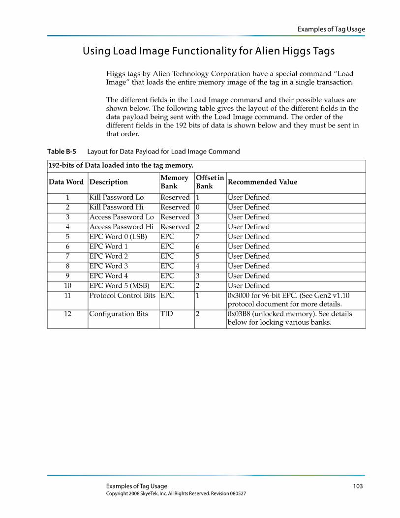
Examples of Tag Usage
Using Load Image Functionality for Alien Higgs Tags
Higgs tags by Alien Technology Corporation have a special command “Load Image” that loads the entire memory image of the tag in a single transaction.
The different fields in the Load Image command and their possible values are shown below. The following table gives the layout of the different fields in the data payload being sent with the Load Image command. The order of the different fields in the 192 bits of data is shown below and they must be sent in that order.
Table B-5 Layout for Data Payload for Load Image Command
192-bits of Data loaded into the tag memory.
Data Word Description Memory Bank
Offset in Bank Recommended Value
1 Kill Password Lo Reserved 1 User Defined2 Kill Password Hi Reserved 0 User Defined3 Access Password Lo Reserved 3 User Defined4 Access Password Hi Reserved 2 User Defined5 EPC Word 0 (LSB) EPC 7 User Defined6 EPC Word 1 EPC 6 User Defined7 EPC Word 2 EPC 5 User Defined8 EPC Word 3 EPC 4 User Defined9 EPC Word 4 EPC 3 User Defined10 EPC Word 5 (MSB) EPC 2 User Defined11 Protocol Control Bits EPC 1 0x3000 for 96-bit EPC. (See Gen2 v1.10
protocol document for more details.12 Configuration Bits TID 2 0x03B8 (unlocked memory). See details
below for locking various banks.
Examples of Tag Usage 103Copyright 2008 SkyeTek, Inc. All Rights Reserved. Revision 080527
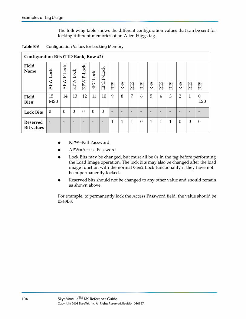
Examples of Tag Usage
The following table shows the different configuration values that can be sent for locking different memories of an Alien Higgs tag
Table B-6 Configuration Values for Locking Memory
Configuration Bits (TID Bank, Row #2)
Field Name
AP
W L
ock
APW
P-L
ock
KPW
Loc
k
KPW
P-L
ock
EP
C L
ock
EPC
P-L
ock
RE
S
RE
S
RE
S
RE
S
RE
S
RE
S
RE
S
RE
S
RE
S
RE
S
Field Bit #
15 MSB
14 13 12 11 10 9 8 7 6 5 4 3 2 1 0 LSB
Lock Bits 0 0 0 0 0 0 - - - - - - - - - -
Reserved Bit values
- - - - - - 1 1 1 0 1 1 1 0 0 0
.
● KPW=Kill Password
● APW=Access Password
● Lock Bits may be changed, but must all be 0s in the tag before performing the Load Image operation. The lock bits may also be changed after the load image function with the normal Gen2 Lock functionality if they have not been permanently locked.
● Reserved bits should not be changed to any other value and should remain as shown above.
For example, to permanently lock the Access Password field, the value should be 0x43B8.
104 SkyeModuleTM M9 Reference Guide
Copyright 2008 SkyeTek, Inc. All Rights Reserved. Revision 080527
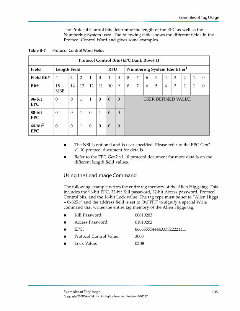
Examples of Tag Usage
The Protocol Control bits determine the length of the EPC as well as the Numbering System used. The following table shows the different fields in the Protocol Control Word and gives some examples.
Table B-7 Protocol Control Word Fields
Protocol Control Bits (EPC Bank Row# 1)
Field Length Field RFU Numbering System Identifier1
Field Bit# 4 3 2 1 0 1 0 8 7 6 5 4 3 2 1 0
Bit# 15 MSB
14 13 12 11 10 9 8 7 6 5 4 3 2 1 0
96-bit EPC
0 0 1 1 0 0 0 USER DEFINED VALUE
80-bit EPC
0 0 1 0 1 0 0
64-bit2 EPC
0 0 1 0 0 0 0
● The NSI is optional and is user specified. Please refer to the EPC Gen2 v1.10 protocol document for details.
● Refer to the EPC Gen2 v1.10 protocol document for more details on the different length field values.
Using the LoadImage Command
The following example writes the entire tag memory of the Alien Higgs tag. This includes the 96-bit EPC, 32-bit Kill password, 32-bit Access password, Protocol Control bits, and the 16-bit Lock value. The tag type must be set to “Alien Higgs – 0x8251” and the address field is set to ‘0xFFFF’ to signify a special Write command that writes the entire tag memory of the Alien Higgs tag.
● Kill Password: 00010203
● Access Password: 01010202
● EPC: 666655554444333322221111
● Protocol Control Value: 3000
● Lock Value: 03B8
Examples of Tag Usage 105Copyright 2008 SkyeTek, Inc. All Rights Reserved. Revision 080527
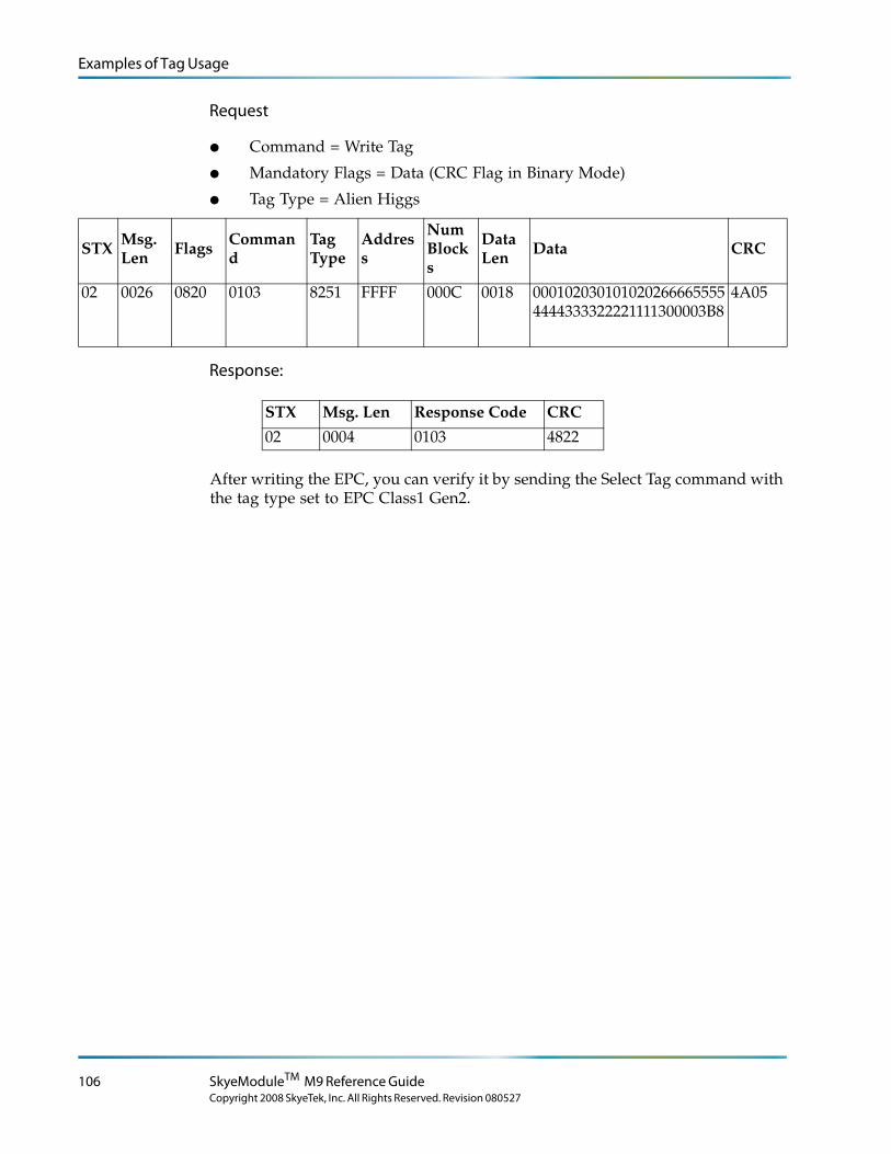
Examples of Tag Usage
Request
● Command = Write Tag
● Mandatory Flags = Data (CRC Flag in Binary Mode)
● Tag Type = Alien Higgs
STX Msg. Len
Flags Command
Tag Type
Address
Num Blocks
Data Len
Data CRC
02 0026 0820 0103 8251 FFFF 000C 0018 0001020301010202666655554444333322221111300003B8
4A05
Response:
After writing the EPC, you can verify it by sending the Select Tag command with the tag type set to EPC Class1 Gen2.
STX Msg. Len Response Code CRC
02 0004 0103 4822
106 SkyeModuleTM M9 Reference Guide
Copyright 2008 SkyeTek, Inc. All Rights Reserved. Revision 080527
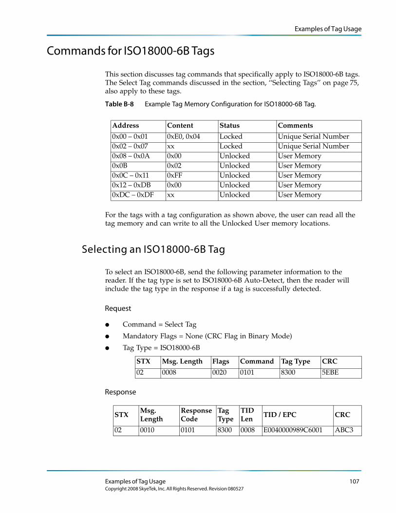
Examples of Tag Usage
Commands for ISO18000-6B Tags
This section discusses tag commands that specifically apply to ISO18000-6B tags. The Select Tag commands discussed in the section, ‘‘Selecting Tags’’ on page 75, also apply to these tags.
Table B-8 Example Tag Memory Configuration for ISO18000-6B Tag.
Address Content Status Comments
0x00 – 0x01 0xE0, 0x04 Locked Unique Serial Number0x02 – 0x07 xx Locked Unique Serial Number0x08 – 0x0A 0x00 Unlocked User Memory0x0B 0x02 Unlocked User Memory0x0C – 0x11 0xFF Unlocked User Memory0x12 – 0xDB 0x00 Unlocked User Memory0xDC – 0xDF xx Unlocked User Memory
For the tags with a tag configuration as shown above, the user can read all the tag memory and can write to all the Unlocked User memory locations.
Selecting an ISO18000-6B Tag
To select an ISO18000-6B, send the following parameter information to the reader. If the tag type is set to ISO18000-6B Auto-Detect, then the reader will include the tag type in the response if a tag is successfully detected.
Request
● Command = Select Tag
● Mandatory Flags = None (CRC Flag in Binary Mode)
● Tag Type = ISO18000-6B
STX Msg. Length Flags Command Tag Type CRC
02 0008 0020 0101 8300 5EBE
Response
STXMsg. Length
Response Code
Tag Type
TID Len TID / EPC CRC
02 0010 0101 8300 0008 E0040000989C6001 ABC3
Examples of Tag Usage 107Copyright 2008 SkyeTek, Inc. All Rights Reserved. Revision 080527
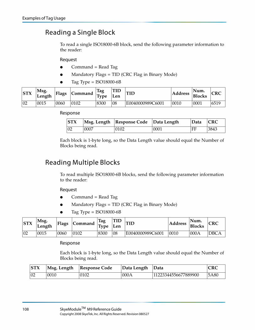
Examples of Tag Usage
Reading a Single Block
To read a single ISO18000-6B block, send the following parameter information to the reader:
Request● Command = Read Tag
● Mandatory Flags = TID (CRC Flag in Binary Mode)
● Tag Type = ISO18000-6B
STX Msg. Length Flags Command Tag
TypeTID Len TID Address Num.
Blocks CRC
02 0015 0060 0102 8300 08 E0040000989C6001 0010 0001 6519
Response
Each block is 1-byte long, so the Data Length value should equal the Number of Blocks being read.
Reading Multiple Blocks
To read multiple ISO18000-6B blocks, send the following parameter information to the reader:
Request● Command = Read Tag
● Mandatory Flags = TID (CRC Flag in Binary Mode)
● Tag Type = ISO18000-6B
STX Msg. Length
Flags Command Tag Type
TID Len
TID Address Num. Blocks
CRC
02 0015 0060 0102 8300 08 E0040000989C6001 0010 000A DBCA
Response
Each block is 1-byte long, so the Data Length value should equal the Number of Blocks being read.
STX Msg. Length Response Code Data Length Data CRC
02 0010 0102 000A 11223344556677889900 5A80
STX Msg. Length Response Code Data Length Data CRC
02 0007 0102 0001 FF 3843
108 SkyeModuleTM M9 Reference Guide
Copyright 2008 SkyeTek, Inc. All Rights Reserved. Revision 080527
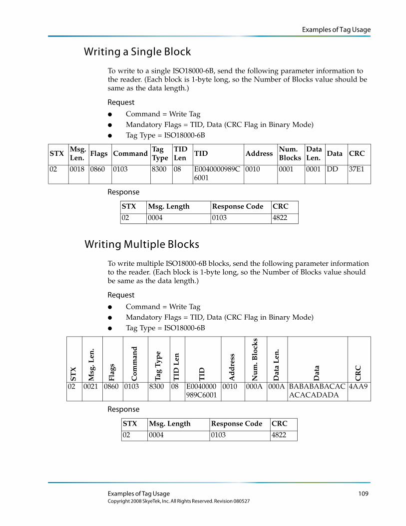
Examples of Tag Usage
Writing a Single Block
To write to a single ISO18000-6B, send the following parameter information to the reader. (Each block is 1-byte long, so the Number of Blocks value should be same as the data length.)
Request● Command = Write Tag● Mandatory Flags = TID, Data (CRC Flag in Binary Mode)● Tag Type = ISO18000-6B
STXMsg. Len. Flags Command
Tag Type
TID Len TID Address
Num. Blocks
Data Len. Data CRC
02 0018 0860 0103 8300 08 E0040000989C6001
0010 0001 0001 DD 37E1
Response
Writing Multiple Blocks
To write multiple ISO18000-6B blocks, send the following parameter information to the reader. (Each block is 1-byte long, so the Number of Blocks value should be same as the data length.)
Request● Command = Write Tag● Mandatory Flags = TID, Data (CRC Flag in Binary Mode)● Tag Type = ISO18000-6B
ST
X
Msg
. Len
.
Flag
s
Com
man
d
Tag
Typ
e
TID
Len
TID
Ad
dre
ss
Nu
m. B
lock
s
Dat
a L
en.
Dat
a
CR
C
02 0021 0860 0103 8300 08 E0040000989C6001
0010 000A 000A BABABABACACACACADADA
4AA9
Response
STX Msg. Length Response Code CRC
02 0004 0103 4822
STX Msg. Length Response Code CRC
02 0004 0103 4822
Examples of Tag Usage 109Copyright 2008 SkyeTek, Inc. All Rights Reserved. Revision 080527
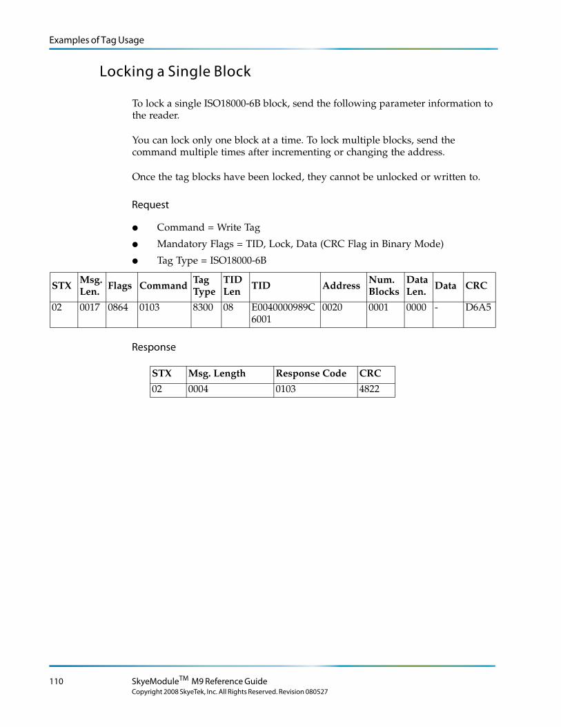
Examples of Tag Usage
Locking a Single Block
To lock a single ISO18000-6B block, send the following parameter information to the reader.
You can lock only one block at a time. To lock multiple blocks, send the command multiple times after incrementing or changing the address.
Once the tag blocks have been locked, they cannot be unlocked or written to.
Request
● Command = Write Tag
● Mandatory Flags = TID, Lock, Data (CRC Flag in Binary Mode)
● Tag Type = ISO18000-6B
STX Msg. Len. Flags Command Tag
TypeTID Len TID Address Num.
BlocksData Len. Data CRC
02 0017 0864 0103 8300 08 E0040000989C6001
0020 0001 0000 - D6A5
Response
STX Msg. Length Response Code CRC
02 0004 0103 4822
110 SkyeModuleTM M9 Reference Guide
Copyright 2008 SkyeTek, Inc. All Rights Reserved. Revision 080527
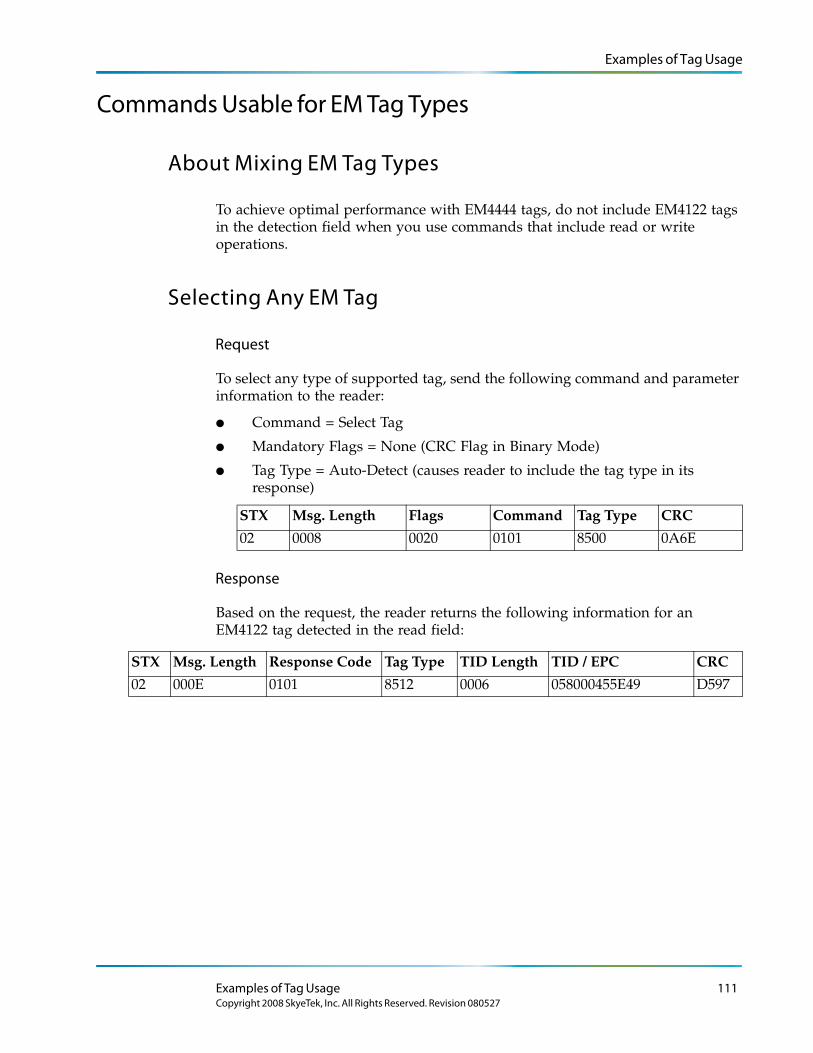
Examples of Tag Usage
Commands Usable for EM Tag Types
About Mixing EM Tag Types
To achieve optimal performance with EM4444 tags, do not include EM4122 tags in the detection field when you use commands that include read or write operations.
Selecting Any EM Tag
Request
To select any type of supported tag, send the following command and parameter information to the reader:
● Command = Select Tag
● Mandatory Flags = None (CRC Flag in Binary Mode)
● Tag Type = Auto-Detect (causes reader to include the tag type in its response)
STX Msg. Length Flags Command Tag Type CRC
02 0008 0020 0101 8500 0A6E
Response
Based on the request, the reader returns the following information for an EM4122 tag detected in the read field:
STX Msg. Length Response Code Tag Type TID Length TID / EPC CRC
02 000E 0101 8512 0006 058000455E49 D597
Examples of Tag Usage 111Copyright 2008 SkyeTek, Inc. All Rights Reserved. Revision 080527

Examples of Tag Usage
Continuously Selecting EM TagsSending the following command sets up continuous monitoring of whatever supported tag type is detected. The first time you send this command, it places the reader into loop mode, which sends a response whenever a tag enters the detection field or when there is a change in the field. Sending any command to the reader turns off loop mode.
Request
To set up continuous monitoring, send the following command and parameter information to the reader:
● Command = Select Tag
● Mandatory Flags = Loop Flag (CRC Flag in Binary Mode)
● Tag Type = Auto-Detect
STX Msg. Length Flags Command Tag Type CRC
02 0008 0021 0101 8500 012A
Response
Start of Loop Mode
The reader returns the following information when it starts loop mode:
STX Msg. Length Response Code CRC
02 0004 81C1 21F0
Reading Tags
The table below shows sample output from the reader after loop mode starts. (There can be any number of reads depending on the number of tags present.)
STX Msg. Length Response Code Tag Type TID Length TID / EPC CRC02 000E 0101 8512 0006 058000455E49 D59702 000E 0101 8512 0006 058000455E49 D59702 000E 0101 8512 0006 058000455E49 D597
.
.
.
02 000E 0101 8525 0006 469900001275 F4B202 000E 0101 8525 0006 058000455E49 F4B202 000E 0101 8525 0006 058000455E49 F4B2
End Loop Mode
The reader exits loop mode when you send another command.
STX Msg. Len Response Code CRC
02 0004 81C1 21F0
112 SkyeModuleTM M9 Reference Guide
Copyright 2008 SkyeTek, Inc. All Rights Reserved. Revision 080527
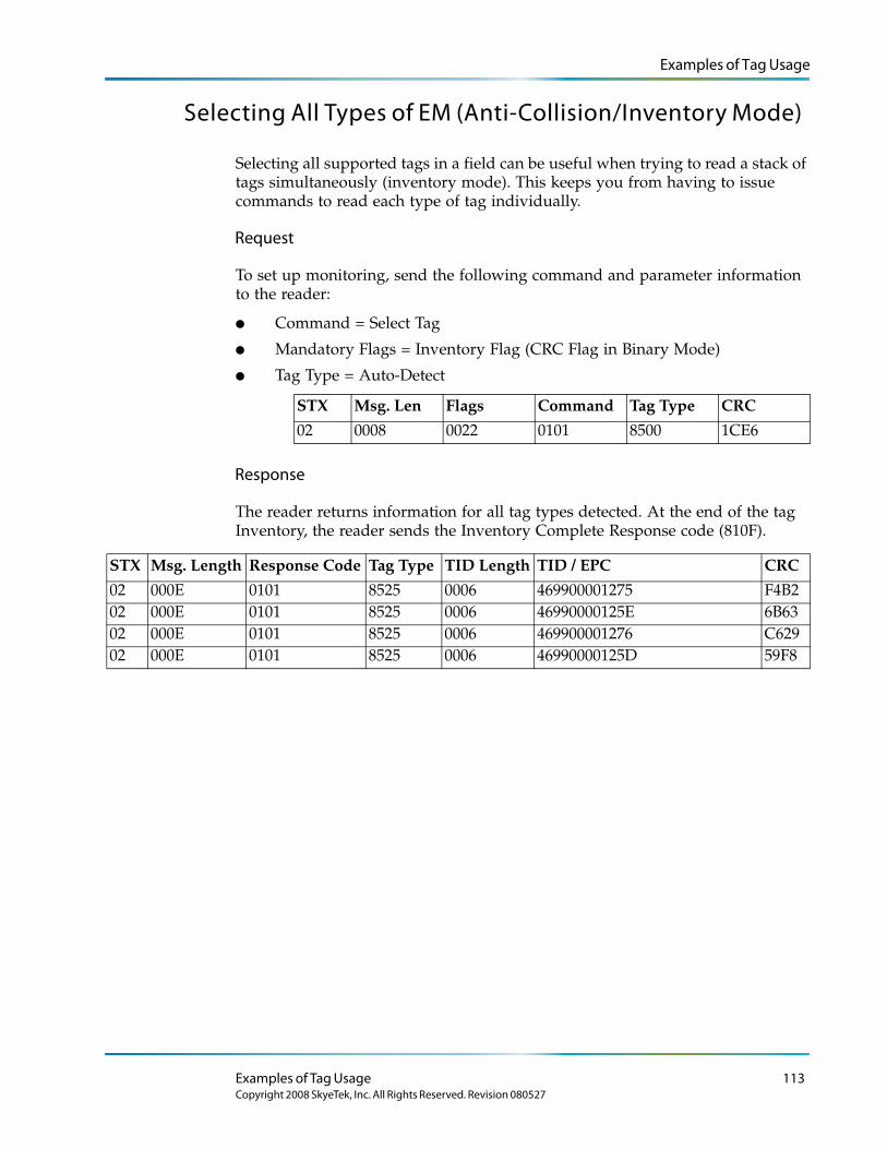
Examples of Tag Usage
Selecting All Types of EM (Anti-Collision/Inventory Mode)
Selecting all supported tags in a field can be useful when trying to read a stack of tags simultaneously (inventory mode). This keeps you from having to issue commands to read each type of tag individually.
Request
To set up monitoring, send the following command and parameter information to the reader:
● Command = Select Tag
● Mandatory Flags = Inventory Flag (CRC Flag in Binary Mode)
● Tag Type = Auto-Detect
STX Msg. Len Flags Command Tag Type CRC
02 0008 0022 0101 8500 1CE6
Response
The reader returns information for all tag types detected. At the end of the tag Inventory, the reader sends the Inventory Complete Response code (810F).
STX Msg. Length Response Code Tag Type TID Length TID / EPC CRC
02 000E 0101 8525 0006 469900001275 F4B202 000E 0101 8525 0006 46990000125E 6B6302 000E 0101 8525 0006 469900001276 C62902 000E 0101 8525 0006 46990000125D 59F8
Examples of Tag Usage 113Copyright 2008 SkyeTek, Inc. All Rights Reserved. Revision 080527
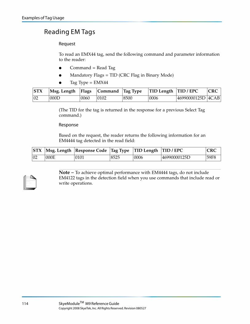
Examples of Tag Usage
Reading EM Tags
Request
To read an EMX44 tag, send the following command and parameter information to the reader:
● Command = Read Tag
● Mandatory Flags = TID (CRC Flag in Binary Mode)
● Tag Type = EMX44
STX Msg. Length Flags Command Tag Type TID Length TID / EPC CRC
02 000D 0060 0102 8500 0006 46990000125D 4CAB
(The TID for the tag is returned in the response for a previous Select Tag command.)
Response
Based on the request, the reader returns the following information for an EM4444 tag detected in the read field:
STX Msg. Length Response Code Tag Type TID Length TID / EPC CRC
02 000E 0101 8525 0006 46990000125D 59F8
L o r e m ip s u m d o lo r s it a me t, c o n s e c te tu e rlo b o r tis p u lv in a r ma g n a . Mo r b i q u is
fe r m e n tu m. In s o d a le s fe u g ia t s e m. S e d u t p e d e . N a m te mp u s . Ma e c e n a s r u tr u mC u r a b itu r n u n c . A e n e a n s c e le r is q u e
S u s p e n d is s e e r a t. Ma u r is u t c uv e s tib u lu m s e m. V iv a mu s e t, v e l le c tu s v ita e
U t o r c i r is u s , c o n v a llis e t, S u s p e n d is s e s u s c ip it v u lp u ta te e lit.
e tr a e n im. S u s p e n d is s e e le me n tu m. S e d e n im lo r e m, s u s c ip it q u is , v e s tib u lu m
in , s u s c ip it n o n , a n te . L o r e m ip s u m d o lo r s it a me t, c o n s e c te tu e r
h a b ita s s e p la te a d ic tu ms t.
S u s p e n d is s e s u s c ip it v u lp u ta te e lit.
. S e d
c o n s e c te tu e r r is u s .
lu c tu s imp e r d ie t.
p r e tiu m c o n d ime n tu m.
Note – To achieve optimal performance with EM4444 tags, do not include EM4122 tags in the detection field when you use commands that include read or write operations.
114 SkyeModuleTM M9 Reference Guide
Copyright 2008 SkyeTek, Inc. All Rights Reserved. Revision 080527
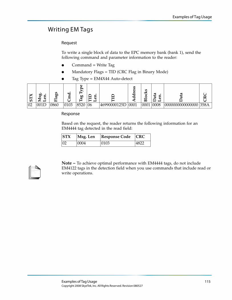
Examples of Tag Usage
Writing EM Tags
Request
To write a single block of data to the EPC memory bank (bank 1), send the following command and parameter information to the reader:
● Command = Write Tag
● Mandatory Flags = TID (CRC Flag in Binary Mode)
● Tag Type = EM4X44 Auto-detect
ST
X
Msg
. L
en.
Flag
s
Cm
d.
Tag
Typ
e
TID
L
en.
TID
Ad
dre
ss
Blo
cks
Dat
a
Len
.
Dat
a
CR
C
02 001D 0860 0103 8520 06 46990000125D 0001 0001 0008 0000000000000000 358A
Response
Based on the request, the reader returns the following information for an EM4444 tag detected in the read field:
STX Msg. Len Response Code CRC
02 0004 0103 4822
L o r e m ip s u m d o lo r s it a me t, c o n s e c te tu e rlo b o r tis p u lv in a r ma g n a . Mo r b i q u is
fe r m e n tu m. In s o d a le s fe u g ia t s e m. S e d u t p e d e . N a m te mp u s . Ma e c e n a s r u tr u mC u r a b itu r n u n c . A e n e a n s c e le r is q u e
S u s p e n d is s e e r a t. Ma u r is u t c uv e s tib u lu m s e m. V iv a mu s e t, v e l le c tu s v ita e
U t o r c i r is u s , c o n v a llis e t, S u s p e n d is s e s u s c ip it v u lp u ta te e lit.
e tr a e n im. S u s p e n d is s e e le me n tu m. S e d e n im lo r e m, s u s c ip it q u is , v e s tib u lu m
in , s u s c ip it n o n , a n te . L o r e m ip s u m d o lo r s it a me t, c o n s e c te tu e r
h a b ita s s e p la te a d ic tu ms t.
S u s p e n d is s e s u s c ip it v u lp u ta te e lit.
. S e d
c o n s e c te tu e r r is u s .
lu c tu s imp e r d ie t.
p r e tiu m c o n d ime n tu m.
Note – To achieve optimal performance with EM4444 tags, do not include EM4122 tags in the detection field when you use commands that include read or write operations.
Examples of Tag Usage 115Copyright 2008 SkyeTek, Inc. All Rights Reserved. Revision 080527
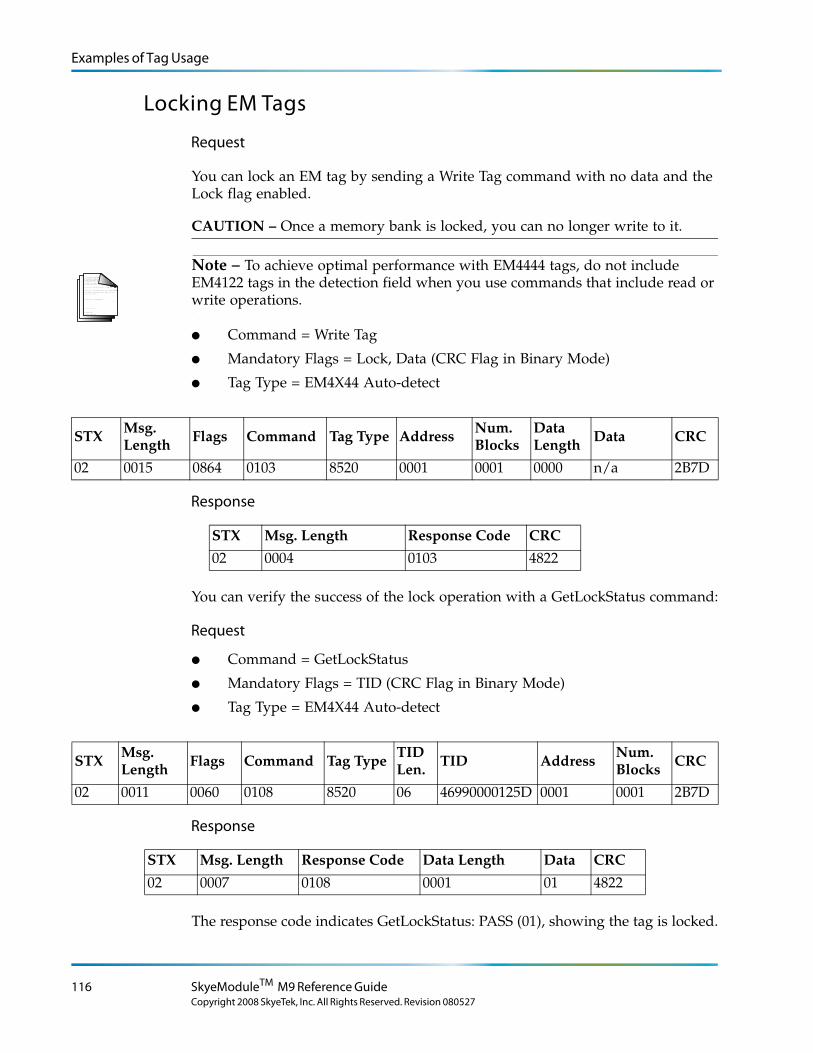
Examples of Tag Usage
Locking EM Tags
Request
You can lock an EM tag by sending a Write Tag command with no data and the Lock flag enabled.
CAUTION – Once a memory bank is locked, you can no longer write to it.
L o r e m ip s u m d o lo r s it a me t, c o n s e c te tu e rlo b o r tis p u lv in a r ma g n a . Mo r b i q u is
fe r m e n tu m. In s o d a le s fe u g ia t s e m. S e d u t p e d e . N a m te mp u s . Ma e c e n a s r u tr u mC u r a b itu r n u n c . A e n e a n s c e le r is q u e
S u s p e n d is s e e r a t. Ma u r is u t c uv e s tib u lu m s e m. V iv a mu s e t, v e l le c tu s v ita e
U t o r c i r is u s , c o n v a llis e t, S u s p e n d is s e s u s c ip it v u lp u ta te e lit.
e tr a e n im. S u s p e n d is s e e le me n tu m. S e d e n im lo r e m, s u s c ip it q u is , v e s tib u lu m
in , s u s c ip it n o n , a n te . L o r e m ip s u m d o lo r s it a me t, c o n s e c te tu e r
h a b ita s s e p la te a d ic tu ms t.
S u s p e n d is s e s u s c ip it v u lp u ta te e lit.
. S e d
c o n s e c te tu e r r is u s .
lu c tu s imp e r d ie t.
p r e tiu m c o n d ime n tu m.
Note – To achieve optimal performance with EM4444 tags, do not include EM4122 tags in the detection field when you use commands that include read or write operations.
● Command = Write Tag
● Mandatory Flags = Lock, Data (CRC Flag in Binary Mode)
● Tag Type = EM4X44 Auto-detect
STX Msg. Length Flags Command Tag Type Address Num.
BlocksData Length Data CRC
02 0015 0864 0103 8520 0001 0001 0000 n/a 2B7D
Response
You can verify the success of the lock operation with a GetLockStatus command:
Request
● Command = GetLockStatus
● Mandatory Flags = TID (CRC Flag in Binary Mode)
● Tag Type = EM4X44 Auto-detect
STXMsg. Length Flags Command Tag Type
TID Len. TID Address
Num. Blocks CRC
02 0011 0060 0108 8520 06 46990000125D 0001 0001 2B7D
Response
The response code indicates GetLockStatus: PASS (01), showing the tag is locked.
STX Msg. Length Response Code CRC
02 0004 0103 4822
STX Msg. Length Response Code Data Length Data CRC
02 0007 0108 0001 01 4822
116 SkyeModuleTM M9 Reference Guide
Copyright 2008 SkyeTek, Inc. All Rights Reserved. Revision 080527
Examples of Tag Usage
Configuring EM 4444 Tags
For EM4444 tags, the system page, memory address 000F, contains configuration information for the tag. You can access individual bytes of the system page using the Read Tag Config and Write Tag Config commands to manage tag configuration. You can also view configuration information using the Get Tag Info or Get Lock Status commands.
● The block size is always 1 for Read Tag Config and Write Tag Config.
● The address specifies a byte from the system page. For example, address 0000 is system page bits 0-7 (LOCK bits), and address 0007 is system page bits 56 to 63.
● Only addresses 0006 and 0007 are writable, as described below.
● Sending a Write Tag Config command to the Tag Talks Only (TTO) byte (address 0006) automatically calls an EM-specific TTO command. This lets you set what the tag sends when the tag transmits in TTO mode. (Although the SkyeModule M9 firmware only decodes the first page of transmitted memory.)
● Sending a Write Tag Config command to the CONFIG byte (address 0007) automatically calls an EM-specific CONFIG command. This lets you set the maximum random delay and the Tx data rate (either 64 Kbps or 256 Kbps).
L o r e m ip s u m d o lo r s it a me t, c o n s e c te tu e rlo b o r tis p u lv in a r ma g n a . Mo r b i q u is
fe r m e n tu m. In s o d a le s fe u g ia t s e m. S e d u t p e d e . N a m te mp u s . Ma e c e n a s r u tr u mC u r a b itu r n u n c . A e n e a n s c e le r is q u e
S u s p e n d is s e e r a t. Ma u r is u t c uv e s tib u lu m s e m. V iv a mu s e t, v e l le c tu s v ita e
U t o r c i r is u s , c o n v a llis e t, S u s p e n d is s e s u s c ip it v u lp u ta te e lit.
e tr a e n im. S u s p e n d is s e e le me n tu m. S e d e n im lo r e m, s u s c ip it q u is , v e s tib u lu m
in , s u s c ip it n o n , a n te . L o r e m ip s u m d o lo r s it a me t, c o n s e c te tu e r
h a b ita s s e p la te a d ic tu ms t.
S u s p e n d is s e s u s c ip it v u lp u ta te e lit.
. S e d
c o n s e c te tu e r r is u s .
lu c tu s imp e r d ie t.
p r e tiu m c o n d ime n tu m.
Note – For additional information on configuration values, refer to the EM4444 data sheet.
Configuration Example
As an example, to configure a tag to have a maximum random delay of 4 kbits and a Tx data rate 64 kbits/s requires the following:
● Setting the delay control bits to 10 (2 decimal). This corresponds to system page bits 61-60.
● Setting the Tx baud rate to 01 (1 decimal). This corresponds to the system page bits 59-58.
● Setting system page bits 63-62 and 57-56 to 0.
The resulting byte made up of these requirements for bits 63-56 thus becomes 00100100 or 0x24. To configure the tag with the above settings, send the Write Tag Config command with the address of 0007 and the data of 24, as shown below:
Examples of Tag Usage 117Copyright 2008 SkyeTek, Inc. All Rights Reserved. Revision 080527
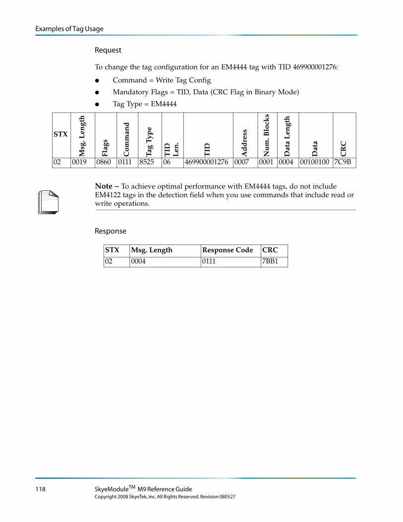
Examples of Tag Usage
Request
To change the tag configuration for an EM4444 tag with TID 469900001276:
● Command = Write Tag Config
● Mandatory Flags = TID, Data (CRC Flag in Binary Mode)
● Tag Type = EM4444
STX
Msg
. Len
gth
Flag
s
Com
man
d
Tag
Typ
e
TID
L
en.
TID
Ad
dre
ss
Nu
m. B
lock
s
Dat
a L
engt
h
Dat
a
CR
C
02 0019 0860 0111 8525 06 469900001276 0007 0001 0004 00100100 7C9B
L o r e m ip s u m d o lo r s it a me t, c o n s e c te tu e rlo b o r tis p u lv in a r ma g n a . Mo r b i q u is
fe r m e n tu m. In s o d a le s fe u g ia t s e m. S e d u t p e d e . N a m te mp u s . Ma e c e n a s r u tr u mC u r a b itu r n u n c . A e n e a n s c e le r is q u e
S u s p e n d is s e e r a t. Ma u r is u t c uv e s tib u lu m s e m. V iv a mu s e t, v e l le c tu s v ita e
U t o r c i r is u s , c o n v a llis e t, S u s p e n d is s e s u s c ip it v u lp u ta te e lit.
e tr a e n im. S u s p e n d is s e e le me n tu m. S e d e n im lo r e m, s u s c ip it q u is , v e s tib u lu m
in , s u s c ip it n o n , a n te . L o r e m ip s u m d o lo r s it a me t, c o n s e c te tu e r
h a b ita s s e p la te a d ic tu ms t.
S u s p e n d is s e s u s c ip it v u lp u ta te e lit.
. S e d
c o n s e c te tu e r r is u s .
lu c tu s imp e r d ie t.
p r e tiu m c o n d ime n tu m.
Note – To achieve optimal performance with EM4444 tags, do not include EM4122 tags in the detection field when you use commands that include read or write operations.
Response
STX Msg. Length Response Code CRC
02 0004 0111 7BB1
118 SkyeModuleTM M9 Reference Guide
Copyright 2008 SkyeTek, Inc. All Rights Reserved. Revision 080527
SkyeModule M9 Version 2.0
Appendix C
SkyeModule M9 Version 2.0
The SkyeModule M9 v2.0 includes all versions of the M9 released before May 4, 2007. It differs from v3.0 in its mechanical, electrical, and environmental specifications and has a narrower temperature range with respect to radio power.
Mechanical Specifications
Mounting Hole Variant
See Figure C-1 on page C-120 for additional dimensions.
Outside dimensions: 53.0 mm x 70.0 mm = 3710 mm2
Height: 9.0 mm
Mounting holes: 3.0 mm diameter 45.0 mm center-to-center (side-to-side) 40.0 mm center-to-center (front-to-back.)
Clearance: Approx. 2.5 mm between edge of mounting hole and edge of printed circuit board (PCB) (side-to-side direction)
Approx. 13.2 mm between edge of mounting hole and front of PCB
Approx. 13.8 mm between the edge of mounting hole and back of PCB
Weight 11.1 grams
SkyeModule M9 Version 2.0 119Copyright 2008 SkyeTek, Inc. All Rights Reserved. Revision 080527
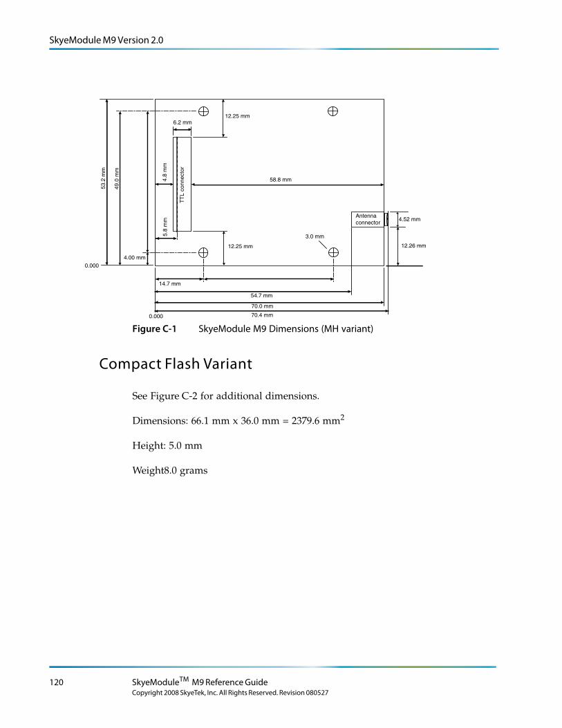
SkyeModule M9 Version 2.0
Spacer text. Spacer text. Spacer text. Spacer text. Spacer text. Spacer text. Spacer text.
14.7 mm
54.7 mm
53.2
mm
49.0
mm
4.52 mm
12.26 mm
70.0 mm
0.000
0.000
4.00 mm
70.4 mm
4.8
mm
3.0 mm
58.8 mmT
TL
conn
ecto
r
Antennaconnector
12.25 mm
6.2 mm
5.8
mm
12.25 mm
Figure C-1 SkyeModule M9 Dimensions (MH variant)
Compact Flash Variant
See Figure C-2 for additional dimensions.
Dimensions: 66.1 mm x 36.0 mm = 2379.6 mm2
Height: 5.0 mm
Weight8.0 grams
120 SkyeModuleTM M9 Reference Guide
Copyright 2008 SkyeTek, Inc. All Rights Reserved. Revision 080527
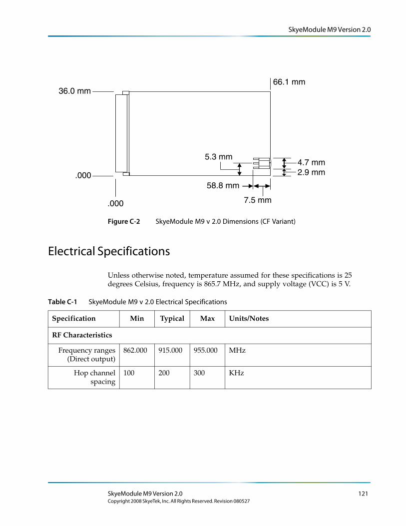
SkyeModule M9 Version 2.0
Spacer text. Spacer text. Spacer text. Spacer text. Spacer text. Spacer text. Spacer text.
36.0 mm
7.5 mm
2.9 mm.000
.000
58.8 mm
66.1 mm
5.3 mm4.7 mm
Figure C-2 SkyeModule M9 v 2.0 Dimensions (CF Variant)
Electrical Specifications
Unless otherwise noted, temperature assumed for these specifications is 25 degrees Celsius, frequency is 865.7 MHz, and supply voltage (VCC) is 5 V.
Table C-1 SkyeModule M9 v 2.0 Electrical Specifications
Specification Min Typical Max Units/Notes
RF Characteristics
Frequency ranges (Direct output)
862.000 915.000 955.000 MHz
Hop channel spacing
100 200 300 KHz
SkyeModule M9 Version 2.0 121Copyright 2008 SkyeTek, Inc. All Rights Reserved. Revision 080527
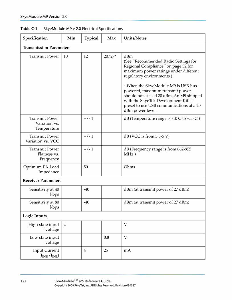
SkyeModule M9 Version 2.0
Transmission Parameters
Transmit Power 10 12 20/27* dBm (See ‘‘Recommended Radio Settings for Regional Compliance’’ on page 32 for maximum power ratings under different regulatory environments.)
* When the SkyeModule M9 is USB-bus powered, maximum transmit power should not exceed 20 dBm. An M9 shipped with the SkyeTek Development Kit is preset to use USB communications at a 20 dBm power level.
Transmit Power Variation vs. Temperature
+/- 1 dB (Temperature range is -10 C to +55 C.)
Transmit Power Variation vs. VCC
+/- 1 dB (VCC is from 3.5-5 V)
Transmit Power Flatness vs. Frequency
+/- 1 dB (Frequency range is from 862-955 MHz.)
Optimum PA Load Impedance
50 Ohms
Receiver Parameters
Sensitivity at 40 kbps
-40 dBm (at transmit power of 27 dBm)
Sensitivity at 80 kbps
-40 dBm (at transmit power of 27 dBm)
Logic Inputs
High state input voltage
2 V
Low state input voltage
0.8 V
Input Current (IINH/IINL)
4 25 mA
Table C-1 SkyeModule M9 v 2.0 Electrical Specifications
Specification Min Typical Max Units/Notes
122 SkyeModuleTM M9 Reference Guide
Copyright 2008 SkyeTek, Inc. All Rights Reserved. Revision 080527
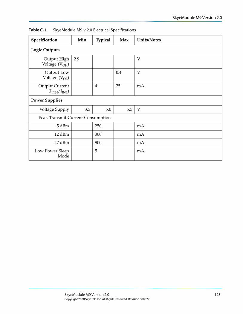
SkyeModule M9 Version 2.0
Logic Outputs
Output High Voltage (VOH)
2.9 V
Output Low Voltage (VOL)
0.4 V
Output Current (IINH/IINL)
4 25 mA
Power Supplies
Voltage Supply 3.5 5.0 5.5 V
Peak Transmit Current Consumption
5 dBm 250 mA
12 dBm 300 mA
27 dBm 900 mA
Low Power Sleep Mode
5 mA
Table C-1 SkyeModule M9 v 2.0 Electrical Specifications
Specification Min Typical Max Units/Notes
SkyeModule M9 Version 2.0 123Copyright 2008 SkyeTek, Inc. All Rights Reserved. Revision 080527
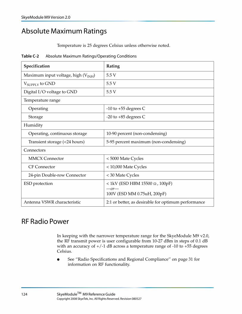
SkyeModule M9 Version 2.0
Absolute Maximum Ratings
Temperature is 25 degrees Celsius unless otherwise noted.
Table C-2 Absolute Maximum Ratings/Operating Conditions
Specification Rating
Maximum input voltage, high (VINH) 5.5 V
VSUPPLY to GND 5.5 V
Digital I/O voltage to GND 5.5 V
Temperature range
Operating -10 to +55 degrees C
Storage -20 to +85 degrees C
Humidity
Operating, continuous storage 10-90 percent (non-condensing)
Transient storage (<24 hours) 5-95 percent maximum (non-condensing)
Connectors
MMCX Connector < 5000 Mate Cycles
CF Connector < 10,000 Mate Cycles
24-pin Double-row Connector < 30 Mate Cycles
ESD protection < 1kV (ESD HBM 15500 Ω , 100pF) —or— 100V (ESD MM 0.75uH, 200pF)
Antenna VSWR characteristic 2:1 or better, as desirable for optimum performance
RF Radio Power
In keeping with the narrower temperature range for the SkyeModule M9 v2.0, the RF transmit power is user configurable from 10-27 dBm in steps of 0.1 dB with an accuracy of +/-1 dB across a temperature range of -10 to +55 degrees Celsius.
● See ‘‘Radio Specifications and Regional Compliance’’ on page 31 for information on RF functionality.
124 SkyeModuleTM M9 Reference Guide
Copyright 2008 SkyeTek, Inc. All Rights Reserved. Revision 080527
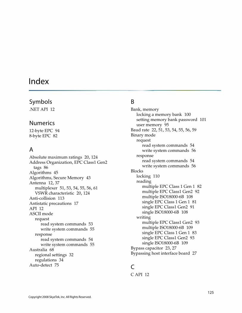
Index
Symbols.NET API 12
Numerics12-byte EPC 948-byte EPC 82
AAbsolute maximum ratings 20, 124Address Organization, EPC Class1 Gen2
tags 86Algorithms 45Algorithms, Secure Memory 43Antenna 12, 37
multiplexer 51, 53, 54, 55, 56, 61VSWR characteristic 20, 124
Anti-collision 113Antistatic precautions 17API 12ASCII mode
requestread system commands 53write system commands 55
responseread system commands 54write system commands 55
Australia 68regional settings 32regulations 34
Auto-detect 75
BBank, memory
locking a memory bank 100setting memory bank password 101user memory 95
Baud rate 22, 51, 53, 54, 55, 56, 59Binary mode
requestread system commands 54write system commands 56
responseread system commands 54write system commands 56
Blockslocking 110reading
multiple EPC Class 1 Gen 1 82multiple EPC Class1 Gen2 92multiple ISO18000-6B 108single EPC Class 1 Gen 1 81single EPC Class1 Gen2 91single ISO18000-6B 108
writingmultiple EPC Class1 Gen2 93multiple ISO18000-6B 109single EPC Class 1 Gen 1 83single EPC Class1 Gen2 93single ISO18000-6B 109
Bypass capacitor 23, 27Bypassing host interface board 27
CC API 12
125Copyright 2008 SkyeTek, Inc. All Rights Reserved.
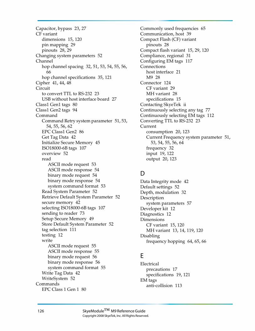
Capacitor, bypass 23, 27CF variant
dimensions 15, 120pin mapping 29pinouts 28, 29
Changing system parameters 52Channel
hop channel spacing 32, 51, 53, 54, 55, 56, 66
hop channel specifications 35, 121Cipher 41, 44, 48Circuit
to convert TTL to RS-232 23USB without host interface board 27
Class1 Gen1 tags 80Class1 Gen2 tags 94Command
Command Retry system parameter 51, 53, 54, 55, 56, 62
EPC Class1 Gen2 86Get Tag Data 42Initialize Secure Memory 45ISO18000-6B tags 107overview 52read
ASCII mode request 53ASCII mode response 54binary mode request 54binary mode response 54system command format 53
Read System Parameter 52Retrieve Default System Parameter 52secure memory 42selecting ISO18000-6B tags 107sending to reader 73Setup Secure Memory 49Store Default System Parameter 52tag selection 111testing 12write
ASCII mode request 55ASCII mode response 55binary mode request 56binary mode response 56system command format 55
Write Tag Data 42WriteSystem 52
CommandsEPC Class 1 Gen 1 80
Commonly used frequencies 65Communication, host 39Compact Flash (CF) variant
pinouts 28Compact flash variant 15, 29, 120Compliance, regional 31Configuring EM tags 117Connections
host interface 21M9 28
Connector 124CF variant 29MH variant 28specifications 15
Contacting SkyeTek iiContinuously selecting any tag 77Continuously selecting EM tags 112Converting TTL to RS-232 23Current
consumption 20, 123Current Frequency system parameter 51,
53, 54, 55, 56, 64frequency 32input 19, 122output 20, 123
DData Integrity mode 42Default settings 52Depth, modulation 32Description
system parameters 57Developer kit 12Diagnostics 12Dimensions
CF variant 15, 120MH variant 13, 14, 119, 120
Disablingfrequency hopping 64, 65, 66
EElectrical
precautions 17specifications 19, 121
EM tagsanti-collision 113
126 SkyeModuleTM M9 Reference GuideCopyright 2008 SkyeTek, Inc. All Rights Reserved.
commands 111configuring 117continuously selecting 112inventory mode 113locking 116reading 114selecting any 111writing 115
Enablingfrequency hopping 64, 65, 66
Encryption 41, 42EPC Class 1 Gen 2 tags
selecting by partial EPC 90EPC Class1 Gen1 tags 80EPC Class1 Gen2 tags 86
killing 102lock functionality 98locking memory bank 100password 96, 97, 98, 101reading
multiple blocks 92single block 91
selecting 87sending tag password 97setting kill password 102writing
12-byte EPC 94multiple blocks 93single block 93tag password 96
ESDprecautions 17protection 18, 124
Estimating read range 37ETSI 68, 69Europe 11, 68
regional settings 32, 68, 69regulations 34
Exampleschanging data integrity strings 50changing encryption and data integrity
settings 49EPC Class1 Gen1 tags 80EPC Class1 Gen2 tags 86initializing secure memory 47, 48ISO 18000-6B tags 107killing tags 102locking functions 98passwords 98
selecting tags 75, 111
FFast inventory 88FCC 34
regional settings 69Firmware
Firmware Version system parameter 51, 53, 54, 55, 56, 57
for Secure Memory 41updates 71
Formatread system command 53system parameter 53write system command 55
Frequencycommonly used 65current 32, 51, 53, 54, 55, 56, 64Frequency Hopping Sequence system
parameter 51, 53, 54, 55, 56, 66hopping 64, 65, 66hopping sequence 32radio 31range 35, 65, 121start 32, 51, 53, 54, 55, 56, 64, 65, 66stop 32, 51, 53, 54, 55, 56, 64, 65, 66
Frequency Hopping Sequence system parameter 64, 65, 66
Functionskey derivation 45
Functions, tag 74
GGet Tag Info command 42GPIO 12, 28, 29, 30, 71
HHardware Version system parameter 51, 53,
54, 55, 56, 57Hash 41, 44HMAC 42, 44Hong Kong 68
regional settings 32regulations 34
Hop channel spacing 32
Index 127Copyright 2008 SkyeTek, Inc. All Rights Reserved.
Hop Channel Spacing system parameter 51, 53, 54, 55, 56, 66
specifications 35, 121Hopping, frequency 32, 54, 55, 56, 66Host interface
board 21bypassing 27connections 21Host Interface Baud Rate system
parameter 51, 53, 54, 55, 56, 59Host Interface Type system parameter 51,
53, 54, 55, 56I2C 21, 25protocol 39
Humidity 18, 124
II2C host interface 21, 25ID, reader 51, 53, 54, 55, 56, 58Initialize Secure Memory command 45Inputs 19, 122Interface, host to reader 21Inventory mode 79, 88, 113ISO18000-6B tags 107
locking single block 110reading multiple blocks 108reading single block 108selecting 107writing multiple blocks 109writing single block 109
JJapan
regional settings 69
KKey 41
Derivation Function 45Kill password 102Killing a tag 102Korea 11
regional settings 32, 68regulations 34
LLBT 51, 53, 54, 55, 56, 69LBT Antenna Gain system parameter 51, 53,
54, 55, 56, 69LEDs 30, 71Listen before talk 51, 53, 54, 55, 56, 68, 69Lock functionality 98
killing a tag 102locking memory bank 100locking single ISO18000-6B block 110setting kill password 102setting memory bank password 101
LockingEM tags 116
Logic, input/output 19, 20, 122, 123LSB 22, 96, 103, 104
MM7
developer kit 12M9
antenna 12CF variant 15, 120connecting to 28connectors 15dimensions 13, 14, 15, 119, 120electrical specifications 19, 121MH variant 119overview 11pin mapping 28, 29pinouts 28, 29RFID functionality 31safety 17security 41specifications 13, 17, 19, 21, 31, 39
MappingCF variant pins 29MH variant pins 28
Mechanical specifications 119Memory 42
bank, locking 100bank, setting password 101bank, user 95banks and blocks 86nonvolatile 74secure 41tag 86
128 SkyeModuleTM M9 Reference GuideCopyright 2008 SkyeTek, Inc. All Rights Reserved.
MH variantdimensions 13, 14, 119, 120pin mapping 28
ModeASCII 53, 54, 55binary 54, 56Data Integrity 42inventory 79, 113operating 62regulatory 32, 51, 53, 54, 55, 56, 68sleep 20, 123
Modulationdepth 32Modulation Depth system parameter 51,
53, 54, 55, 56, 67Mounting hole variant 119MSB 25, 86, 96, 103, 104, 105Multiplexer 51, 53, 54, 55, 56, 61MUX Control system parameter 51, 53, 54,
55, 56, 61
NName, reader 51, 53, 54, 55, 56, 59NET API 12New Zealand 68
regional settings 32North America 11, 68
regional settings 32regulations 34
OOperating Mode system parameter 51, 53, 54,
55, 56, 62Output
frequency 35, 121logic 20, 123power 32
Overviewsecurity 41SkyeModule M9 11system parameters 51
PParameter
receiver 35, 122
system 51system, descriptions 57transmission 35, 122
Parameter, systemchanging 52formats 53
Passwordkilling tag 102locking memory bank 100locking tag memory 98setting for memory bank 101setting kill password 102tag, sending 97tag, writing 96
Pin mappingCF variant 29LED 71MH variant 28SkyeModule M9-CF 28
PinoutSkyeModule M9-CF 29
Plaintext 41Port
direction 51, 53, 54, 55, 56, 60value 51, 53, 54, 55, 56, 61
Powercycle 52output 32Power Level system parameter 51, 53, 54,
55, 56, 63radio 31, 124supply for bypassing host interface board
with USB 27supply for conversion circuit 23transmit 35, 122USB 27values 63
PRNG 44Problem solving 71Product Code system parameter 51, 53, 54,
55, 56, 58Pseudo-random frequency hopping 66Pulse shaping 68
RRadio functionality 31, 124
radio test modes 33specifications 35, 121
Index 129Copyright 2008 SkyeTek, Inc. All Rights Reserved.
Range, estimating 37Ratings
absolute maximum 20, 124temperature 18, 20, 124
Readrange 37Read System Command Format 53
Read Tag Data commandCommand
Read Tag Data 42Read/reader/reading
Read System Parameter command 52Reader
host interface 21Reader ID system parameter 51, 53, 54, 55,
56, 58Reader Name system parameter 51, 53, 54,
55, 56, 59Readers/reading
reader ID 58sending commands 73
Readerware 41Reading
multiple EPC Class 1 Gen 1 block 82multiple EPC Class1 Gen2 blocks 92multiple ISO18000-6B blocks 108single EPC Class 1 Gen 1 block 81single EPC Class1 Gen2 block 91single ISO18000-6B block 108
Reading EM tags 114Receiver, parameters 35, 122Regional
compliance 31settings 32, 68, 69
Regulatorycompliance 11, 34mode 32power ratings 35, 122Regulatory Mode system parameter 51,
53, 54, 55, 56, 68Request
ASCII read system command 53ASCII write system command 55binary read system command 54binary write system command 56
Reset 52Response
ASCII read system command 54ASCII write system command 55
binary read system command 54binary write system command 56time 62
Retrieve Default System Parameter command 52
RFID functionalityradio power 31
RS-232 22converting TTL 23
SSafety 17Secure Memory
algorithms 43commands 42Initialize Secure Memory command 45security level 45Setup Secure Memory command 49
Secure operations 41, 96, 97, 98, 100, 101, 102security level 45
Selecting tags 75anti-collision mode 113any EM tag 111, 114, 115, 116any tag 76by partial EPC 90by TID 89continuous 77, 112EPC Class1 Gen1 80EPC Class1 Gen2 87inventory mode 79, 113ISO18000-6B 107
Sendingcommands to reader 73
Sending tag password 97Sensitivity 35, 122Serial number system parameter 51, 53, 54,
55, 56, 57Setting
kill password 102regional 32
Setup Secure Memory command 49Shared key 41Signing 41Singapore 68
regional settings 32regulations 34
SkyeModule M7developer kit 12
130 SkyeModuleTM M9 Reference GuideCopyright 2008 SkyeTek, Inc. All Rights Reserved.
SkyeModule M9compact flash variant 15, 120connecting to 28connectors 15dimensions 13, 14, 15, 119, 120electrical specifications 19, 121mounting hole variant 119overview 11pin mapping 28, 29pinouts, CF 28, 29RFID functionality 31safety 17security 41specifications 13, 17, 19, 21, 31, 39
SkyeTekcontacting iisupport ii
SkyeTek Protocol v3 22, 24, 39SkyeWare software 12
command testing 12configuration functions 12demo functions 12setup wizard 12
Sleep Mode 20, 123Software
C API 12command testing 12configuration functions 12demonstration functions 12Readerware Security Suite 41setup wizard 12SkyeWare 12specification 39
Spacing, hop channel 66Specifications 13, 17, 19, 21, 31, 39
absolute maximum ratings 20, 124connector 15electrical 19, 121host interface 21mechanical 119radio 31regional compliance 31software 39temperature 18, 20, 124
SPI host interface 21, 24Start frequency 32Start Frequency system parameter 51, 53, 54,
55, 56, 64, 65, 66Stop frequency 32
Stop Frequency system parameter 51, 53, 54, 55, 56, 64, 65, 66
Store Default System Parameter command 52Summary of tag functions 74Support
SkyeTek iiSystem parameter 51
changing 52Command Retry 51, 53, 54, 55, 56, 62Current Frequency 51, 53, 54, 55, 56, 64description 57Firmware Version 51, 53, 54, 55, 56, 57formats 53Frequency Hopping Sequence 51, 53, 54,
55, 56, 64, 65, 66Hardware Version 51, 53, 54, 55, 56, 57Hop Channel Spacing 51, 53, 54, 55, 56, 66Host Interface Baud Rate 51, 53, 54, 55, 56,
59Host Interface Type 51, 53, 54, 55, 56, 59LBT Antenna Gain 51, 53, 54, 55, 56, 69Modulation Depth 51, 53, 54, 55, 56, 67MUX control 51, 53, 54, 55, 56, 61Operating Mode 51, 53, 54, 55, 56, 62Power Level 51, 53, 54, 55, 56, 63Product Code 51, 53, 54, 55, 56, 58Reader ID 51, 53, 54, 55, 56, 58Reader Name 51, 53, 54, 55, 56, 59Regulatory Mode 51, 53, 54, 55, 56, 68Serial Number 51, 53, 54, 55, 56, 57Start Frequency 51, 53, 54, 55, 56, 64, 65, 66Stop Frequency 51, 53, 54, 55, 56, 64, 65, 66summary 51User Port Direction 51, 53, 54, 55, 56, 60User Port Value 51, 53, 54, 55, 56, 61
TTag
auto-detect 75commands 111configuration 117continuously selecting 77, 112EPC Class 1 Gen 1 80EPC Class 1 Gen 2 86functions 74ID 89, 90ISO18000-6B 107ISO18000-6B, selecting 107
Index 131Copyright 2008 SkyeTek, Inc. All Rights Reserved.
killing 102locking 98memory 86selecting 75types
EM 111EPC Class1 Gen1 80EPC Class1 Gen2 86ISO18000-6B 107regional 32supported 32
Taiwan 68regional settings 32regulations 34
Temperatureratings 18, 20, 124vs. transmit power variation 35, 122
Testing 12, 33, 71TID 89, 90Timing 62, 68Transmit
parameters 35, 122peak current 20, 123power 35, 122
Troubleshooting 71TTL 21, 22
converting to RS-232 23
UUpdating firmware 71USB 21User
memory bank 95User Port Direction system parameter 51,
53, 54, 55, 56, 60User Port Value system parameter 51, 53,
54, 55, 56, 61
VVersion
firmware 51, 53, 54, 55, 56hardware 51, 53, 54, 55, 56, 57
Visual indicators 71
WWizard 12Write
12-byte EPC 94EM tags 115multiple EPC Class1 Gen2 block 93multiple ISO18000-6B block 109single EPC Class 1 Gen 1 block 83single EPC Class1 Gen2 block 93single ISO18000-6B block 109tag password 96user memory bank 95Write System Command Format 55
Write Tag Data command 42Write/writing
WriteSystem command 52
132 SkyeModuleTM M9 Reference GuideCopyright 2008 SkyeTek, Inc. All Rights Reserved.