skewed multi-beam bridges with precast box girders : final...
TRANSCRIPT

Co HES - -- -_ CtIH .:==::::=::::!' '
,
DEPARTMENTAL RE EARCH
Number 206-IF
J 1 '
SKEWED IULTI-BEAM BRIOGES WITH PRECAST
BOX GIRDERS
STATE DEPARTMENT OF HIGHWAYS AN D PUBLIC TRANSPORTATION
~>:"/~::: :.:: :; ; .-.':: c:.:- .

..
I
rlTLE PAGE
1. Report No. 2. Government Accession No.
filHWATX77206-1F , LOO7983 r
4. Title and Subtitle 5. Report Date ,September 1977
SKEWED MULTI~BEAM BRIDGES WITH PRECAST BOX GIRDERS 6. Performing Organization Code
7. Authorr s) 8. Performing Organi :ration Report No.
John J. panak 206-1F
9. Performing Oraani%ation Nome and Address 10. Work Unit No. The Bri ge Division Texas State Department of Highways 11. Contract or Grant No.
and Public Transportation 1-5-76-206 Austin .. Texas 78701 13. Type of Report and Period Covered
12, Sponsoring A{;ency Name and Address of Highways Final Texas S ate Department
Aug 1975 Sept 1977 and Public Transportation -Tra nsportation Planning Division 14. Sponsoring Agency Code
Box 5051, Austin, Texas 78763 >
15. Supplementary Notes Prepared in cooperation with the U.S. Department of Transportation, Federal Highway Administration. Research Study Title: "Wheel Load Distribution for Precast Multi-Beam Box Girders"
16, Abstract
The research completed under this project demonstrates the reduction in required design moment that can be achieved by consideration of the skew angle and aspect ratio of a multi-beam bridge. It is primarily directed toward precast multi-beam box bridges of the type currently built in Texas. Other similiar multi-beam or solid slab structures with sim:pl,:~ spans can also be handled.
A data generator computer input assist was written which provides the data for a previously developed program so that accurate solutlons can be obtalned wlth a mlnlmum of lnput.
A field load test was performed on a full-scale skewed bridge. Comparison of the measured values with those predicted by the analysis methods was good.
17. Key Words
Highway Bridges, multi-beam precast bridges, computer analysis, load tests
18. Distribution Statement
No Restrictions. This document is available through the National Technical Information Service, springfield, Virginia 22161
19. Security Classif. (of this report) 20. Security Classif. (of this page) 21. No. of Pages 22. Price
Unclassified Unclassified 101
Form DOT F 1700~7 (a.S9)

SKEWED MULTI-BEAM BRIDGES WITH PRECAST BOX GIRDERS
by
John J. Panak
Research Report Number 206-1F
Wheel Load Distribution for Precast Multi-Beam Box Girders
Research Study 1-5-76-206
Conducted by
The Bridge Division
Texas State Department of Highways and Public Transportation
in cooperation with the .U.S. Department of Transportati on
Federal Highway Administration
September 1977

•
PREFACE
The report presents a study of skewed multi-beam precast box beam bridges
of the types currently used in Texas. A data generator computer input assist
was developed for analysis by an existing complex program. The method of
analysis can be applied to most multi-beam bridges. A load test of a full
scale structure provided validation .
The work was supported by the Texas State Department of Highways and
Public Transportation in cooperation with the U.S. Department of Transportations
Federal Highway Administration.
Mr. Charles C. Terry of the Bridge Division provided assistance throug~
out the course of the project, and his help is greatly appreciated. The advice
of Mr. Robert L. Reed, of the Bridge Division, is also appreciated.
John J. Panak
September 1977
ii

SUMMARY
This study was made to help determine more accurate design live load
values for-skewed multi-beam bridges constructed with precast, prestressed box
beam sections of the types now in use in Texas. The results demonstrate that
as much as 40 or 50 percent reduction in design live load moment is achieved by
consideration of the skew angle for these structures. The span aspect ratio
was also found to have an appreciable effect.
A data generator computer input assist was developed to allow simple
application of the analysis method. The procedure allows any variation of skew,
structure width, span, and box depth or width to be analyzed.
A field test of a full-scale skewed structure was performed which provided
good correlations between predicted and measured response to a heavily loaded
truck. These correlations add significant confidence to the user of the devel
oped analysis techniques.
iii

IMPLEMENTATION
This project has demonstrated that a significant reduction in design live
load moment can be achieved inmuTti-beam bridges by consideration of the skew
angle and span aspect ratio. It is recommended that the developed data genera
tor computer input assist be used for future design of these structures.
DISCLAIMER
This report reflects the views of the author who is responsible for the
facts presented. The contents do not necessarily reflect the views or policies
of the Bridge Division, Texas State Department of Highways and Public Transporta
tion, or the Federal Highway Administration. This report does not constitute
a standard, specification, or regulation.
There was no invention or discovery made under this contract which is
patentable.
iv

TABLE OF CONTENTS
PREFACE
SUMMARY
I MPLEMENTA TI ON
CHAPTER 1. INTRODUCTION
Program Data Generator Field Load Test. . Application to Design
CHAPTER 2. MULTI-BEAM BRIDGES
AASHTO Des ign Equations . . . . . . Background for the Current AASHTO Equations
CHAPTER 3. THE ANALYSIS METHOD
Skewed Supports Data Generated .
CHAPTER 4. PARAMETER STUDIES
Skew Angle . • Twisting Stiffness Aspect Ratio ..... Load Placement and Skew Arrangement
CHAPTER 5. THE DATA GENERATOR PROGRAM
Data Input . . . . . . Parent and Offspring Problems . Data Errors . Computed Results
CHAPTER 6. THE FIELD TEST
The Test Structure The Test Loading
v
· i i
iii
iv
1 1 2
8 9
· 13 13
18 20
• 21 · 21
· 25 29
· 29 • 30
32 · 32

Load Placements • Instrumentation • Data Recordi ng • • Summary of Measurements . Computer Analysis Comparisons
CHAPTER 7. CONCLUSIONS AND RECOMMENDATIONS
Verification of Analysis Methods Impact on Construction Costs
REFERENCES
APPENDICES
Appendix A. Field Load Test Data • • . . • Appendix B. Guide for Data Input, Program SLBDG 2 Appendix C. Notation and Listing, Program SLBDG 2 Appendix D. Typical Output, Program SLBDG 2
36 36 42 43 46
47 47
49
50 60 71 84
vi

CHAPTER 1. INTRODUCTION
The objective of this study was to determine the approximate wheel load
distribution for skewed precast box beam bridges of the type currently in use
in Texas. At the outset, it was anticipated that a significant reduction in
the required design moment could be achieved. The effect of skew was to be
incorporated in the study since it produces twisting effects which are well
resisted by a multi-beam structure with large shear keys such as used in Texas.
Program Data Generator
As a part of the study, a data generator computer input assist was devel
oped to produce the necessary mass of data needed to effectively analyze a
skewed structure by the solver program which had previously been developed
during the period 1966 through 1972 (Ref 8). The data generator proved to re
quire somewhat more effort to develop than first anticipated. Documentation
of the data generator and instructions for its use are included herein.
Field Load Test
A field load test was performed during July 1977 of a full-scale skewed
multi -beam box structure. Compari son of the measured values wi th those pre
dicted by the analysis methods developed during the project were exceptionally
good. The test correlation adds significant confidence to the user of the in
cluded analysis techniques for any structure configuration using precast box
beams now used in Texas.

2
Application to Design
The project proposal indicated that charts or graphs might be prepared so
that a designer could enter directly with his box beam structure configuration
and obtain the required live load design moment. This has proven very diffi
cult to do and still retain accuracy. The design moment per box is almost
impossible to predict accurately especially when a mixture of box widths
exists. Therefore, it was decided during later stages of the project to
direct the emphasis toward demonstrating the beneficial effect of skew which
significantly reduces the longitudinal live load design bending moment. Em
phasis was also placed on making the data generator easy to use so that with
as little data as possible, design moments for a particular structure can be
obtained directly. As will be shown, this objective has been accomplished.
A significant reduction in the required design moment can be achieved by
using the proven analysis methods presented within this report.

CHAPTER 2. MULTI-BEAM BRIDGES
A typical skewed multi-beam precast concrete bridge as currently con
structed in Texas is shown in Fig 1. The Texas State Department of Highways
and Public Transportation (hereafter referred to as DHT) began building these
precast multi-beam structures in 1969 and their use has increased steadily
since then. The general cross-sections are as shown in Fig 2. The beams are
cast with the sides formed using the same or similar configurations that have
been used for precast beams in the state since about 1958. The beams are
placed side by side and a cast-in-place shear key is placed in the resulting
space left between beams. As can be seen in Figs 2, 3, and 4, the final cross
section has large effective webs between the voids. The direct cost of these
bridges is currently about fifty percent higher than comparable precast beam
and slab structures, but offsetting this added cost is the reduction in ap
proach roadway earthwork due to the more shallow overall structure depth.
The construction schedule can also be greatly accelerated, thus reducing pub-
1ic inconvenience. These bridges are considered more durable than cast-in
place bridges due to the use of high-strength precast concrete. It is hoped
that increased usage in the future will reduce the direct cost of these bridges.
AASHTO Design Equations
The desi gn of multi -beam precast concrete box girders was, unt"il 1974,
done with little regard to their inherently different behavior under live
1 oadi ng as compared to customary beam and sl ab structures. The AASHTO 1965
specifications (Ref 3) provided that the distribution for multi-beam bridges
should not exceed that for a reinforced slab. This provision implied that pre-
3

"_::.l:S1 r j" I 5 Spa. at S!..O"· 40',0· • lit,s" _~I I TV. T301 Railing I . ~ -- ~=-=' =!=-======;i==Fa=c=e =o=f=R=a=iI:=.;r-===-~~----I l=====F====
~=====9
~3~='=======~============ ~in of Brid e
Inside face
Abu!. BkWI"-~""~U=--:"=======1-===========J:l=' ====B=e=nt=======~ S!..O" /$ .rI=====
~======~~=======~~'==============9
-:1 r~~I~~---::,~;:L,~~~~~---_:~~--------:.:-------d ~~ TV. 1'301 RaIling
PLAN
Width
42',0" Roadway
24'.0"
t:.:=C-L RdwV.
IS'-O"
T301
5 Boxes at 3!..11314', 'te" Joints 5 Boxes at 3!..11~" lf8' Joint$
TRANSVERSE SECTION
Fig 1. Typical skewed multi-beam bridge usinq eleven Type 4-20 precast box sections.
4
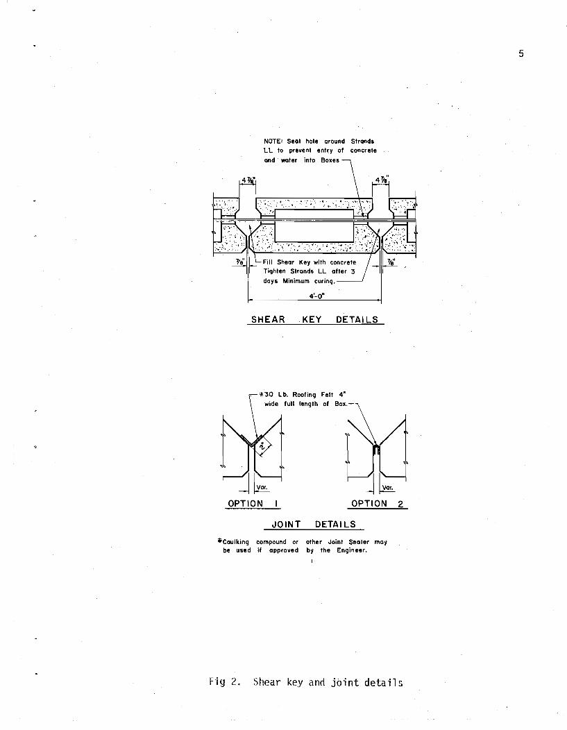
NOTE: Seal hole around Strands LL 10 prevent entry of concrete
and water into Boxes
.... " .~ '," ...
Minimum curinq.
4'_0'1
SHEAR KEY DETAILS
*30 Lb. Roofing Felt 4" wide full length of Box.
OPTION OPTION 2
JOINT DETAILS
.Caulking compound or other Joint Sealer may be used it approved by the Engineer.
Fig 2. Shear' key and joint details
5

Ft Spans)
----_ .. _-...".
-r-~_
:~ \0 -'If- Ie,
I ~i J_k= '-l. ,
I i I
~L~·""·i l-~-" ~- IE ~-~ .... __ I 4-46 5-46 (100-140 Ft Spans)
I 10 I" ~4.J~-~W .. ~" ~.+ ....... IE.9.~_._j 4-34 5-34 (70-100 Ft Spans)
Fig~. Typical precast multi-beam box sections.

/:3~·L'- Face of Real Clea," /loadwall' '" --I ___ "--.1' ____ _
~ D QIUllnTUhM~~'7$ I ~gs I
J V" Face of Rail :::j'-Jif . '"
I ' I i
o D 26' Rdwy I Z Boxes 1ii3!//;';'¥ 4-Boxes 1Ol4:'11~" /~~"jfs .. I
,3"1' Rd;!. 480XI$ 93'./1'%", ..,. BOX~$ 'iii ..,.://3q.", /4+ ".I/'5 • I 4l'RtitY.Y ~ 6BoXIS "ii3~//!4", 4 BO'(I$ ii4~//~", /"",/Is_.. ..I 48' Rtiwy t /OBoxes (8 4:11%'~ /"",/fs ... /
JOINT AT CENTERLINE OF BRIDGE
(J~f=F"ce of Nail. Clear ~oCfd",ay . Fac. of Rail=Cj t~~~
j ! I 1
~I 101} hOI IIQQ [ 101 I~ , I
Z6'Rdwy 7/Joxes $ 3~11~", /'J~N,/fs !
34'RdfVJI 9 Boxes 'Ii J'..II~·, 1~"Jt$ 4Z'Rdwy IIBole,$ ii.J~/I!4"t rJ1';ls
"'/8' RdtY.Y 5 Boxes 1i1.J:II~; 6' .Boxes ii) +'-I/!:f, FUJI$' I "'1
NO JOINT AT CENTERLINE OF BRIDGE
Fig ,4~ Typical bridge cross-sections. ""-J

cast multi-beams were as good as solid slabs for distribution. The distribu
tion formula at that time and still current for slabs is given by
E = 4 + 0.6S (1)
where E is the distribution in feet and S is the span. For bridges with
spans of 30 to 50 feet and longer, the resulting distribution is 5.8 to a maxi-
mum of 7.0 feet. This formula has remained since it was changed from an even i';
more conservative formula in 1961 (Ref 4) which was
10N + W E = 4N
where Nand W were numbers of lanes and bridge width respectively. For
uniform 12 foot increments of lanes and widths, Eq 2 gave approximately a 5.5
foot slab distribution.
(2)
In 1970~ as a result of extensive analytical investigations at Iowa State
University by Sanders, Elleby, and Watanabe (Refs 10 and 12), a revised series
of equations was proposed to AASHTO in 1974 (Ref 2). This interim specification
is directed particularly toward multi-beam bridges, and for the first time in
the history of the AASHTO bridge specifications, the torsional stiffness of the
beam members and the aspect ratio of the structure were included in the effec
tive distribution. These parameters were known to influence load distribution
for many years, but simple methods to include them had not been available.
The amount of bending moment for a multi-beam structure as now incorporated in
Ref 2 is computed by applying the following fraction of a wheel load (line of
wheels) to each beam (12 NL + 9) j N
9
where NL is the whole number of design 12 foot lanes, Ng is the number of
beams, and C is a stiffness parameter given by
( 3)
C = K WjL (4)

9
where K is a constant varying from 0.7 to 2.2 with 1.0 recommended for box
section multibeams, W is the overall width of the structure, and L is the
span. The last term in the denominator of Eq 3 is neglected if C exceeds 3
which is only true for extremely wide structures with short spans. The K
stiffness factor is supposed to help account for the variations in torsional
rigidity (Ref 10), but as can be seen by Eq 3, the factor C has very little
effect on the resulting distribution. This study will show that for orthognal
structures, the torsional stiffness does in fact have little effect on the
maximum bending moments, but for skewed structures it is a significant parameter.
This has also recently been observed by Kennedy and Gupta (Ref 6). Unfortunately,
of the three general structural types investigated in Ref 10(beam and slab,
multi-beams, and cast-in-place concrete box girders), the multi-beam formulas
were the least verified by comparison to experimental data. In addition, they
were developed for only simple span and non-skewed structures.
Background for the Current AASHTO Equations
The current multi-beam distribution equations given above were developed
by Sanders, Elleby, and Watanabe (Refs 10 and 12). Various bridge configura
tions over a range of spans and widths were studied by selectively varying the
bending and twisting stiffness. The resulting equations are a best fit to a
series of curves developed for several different multi-beam sections including
channel (weak in torsion) cross-sections. Thus, the equations do not specifi
cally suit the case of closed-box cross-sections which are almost as strong in
torsion as solid slabs.
The method of analysis used by Watanabe (Ref 12) was an articulated
plate analysis with limiting assumptions: (1) that the structure was orthogo
nal (no skew), (2) that the shear key connections were assumed completely
hinged (see further comment below), (3) that the wheel loads were assumed at

10
mid-span, and (4) that Poisson1s ratio was neglected.
The computational technique used assumed, (1) that the plate was of the
same uniform bending stiffness in the longitudinal direction at all transverse
locations, (2) that the transverse stiffness was taken as zero not only at
the location of the shear keys but also at the areas in between, and (3) that
the load was represented as a harmonic series.
Limiting assumption (2) and computational assumption (2) above disregard
the effect of transverse be'l1ding and stiffness characteristics between the
shear keys. This area can be proportionately quite large if the box depth is
shallow in relation to the box width. The Texas DHT uses box width modules of
4 and 5 feet which are combined to achieve the desired total structure width.
Thus, for the multi-beam box girders of the type shown in Figs 1 thru 5, if
the distribution equations (Ref 2) or analysis procedure (Ref 12) are used,
significant omissions in transverse structural strength result.
Therefore, as a partial result of the limitations in the current AASHTO
distribution equations, and recognizing that many structures are built with
skewed geometry as shown in Figs 1 and 5, the research descr'ibed in this re
port is deemed to be of significant importance to the Texas DHT.

__ I- ,,'- Span leT/?; ~L t &nf c'~ 311 ~m&X Leng!:~L-@h· "!-*'"
~I !PL.(ji~),C ~- IL-rPy;'N :1 " I I . I 't \ " ~t -- -- ------4.-----------'~ ~ ~
~
:",<IJ ,~ ,
\ L __________ ~,-- _ ....l
\ r - --------, '. I I t L ___ . _______ _ 1... ___________ \.... ___________ .J
r------~------~-------------,
;:==::~~~~~~~-~-2--~-~r_tBenf--A ,-------'. \ :====~~~~~~~~. \. -------- --, ,\
I ~ ,---------- --------~::::~, ==~;;;;;;;;~N~O;;;;;;:R~M~A~L===;.;;;;;~~;.;JD~from 1/ t sml~L~'-:=-=-===-=-=-l.~\·Lr;;;;;;;;;;.;;;;.::,;:,;:,;;-::-::;;-::;;-=J
ISO SKEW
1"" ~pon Lel?Jfh:£ u .. , H
1t" Sp:m Lengfh:L -I
3%1 tJOxien9-fh < L - rJ Yt;* . 3~G .' !" (L-rJY8')+c n (L-r;~')+c :1 ..... ~ I .. • ! - ---'-----....; "'i! .: . .'
4Y4 j &x Len:fh" L -aYe 14~ IF (i-BYe)+-? :.. (£-8'2")+2 :Ii '...:.. ~ r-------- ~~\\------ ~.
• ~ I ~.\ '-(' 3 L_________ ~ L___ '~
r---- ----- ------------ j \\ 30·
I~ L _________ ~~----,.-----.J ~,~ ~ /
r---------~-----------,-~
~ 1? ~
~
:..'-~ ~ ....
t&:nt
----- ------~ 'f! I ~... I ~ L______ _,_~____ _.c
r------ --------- ., r-- ---,-- ----,
L~ __ -------~
_ ___ -J
'\ -- -, -- ' L ,,-----' -~ i---------- \\---~~=---' ----c--"--- __ J ---~
30° SKEW t Diaf'rom q tJ. strand Ll 45° SKEW
Fig 5. Typical span details. Longer spans have more diaframs.
~&:nf
..... ....

CHAPTER 3. THE ANALYSIS METHOD
The method of analysis used throughout the study was developed on another
research project during the period from 1966 through 1972. That project was
"Development of Methods for Computer Simulation of Beam-Columns and Grid-Beam
and Slab Systems," the major results of which are summarized in its final re
port (Ref 9). The specific analysis method used was one documented in Ref 8
which presents a computer program for the discrete-element analysis of isotro
pic or orthotropic slabs and plates on elastic supports. The program has been
"in successful day-to-day use by engineers of the DHT and by other agencies and
organizations for several years. The program allows for the free variation of
stiffness, supnorts, and loads. Skewed support conditions can be easily han
dled by appropriate definition of the support locations which procedure is
described below. Another similar analysis procedure (Ref 11) was also avail
able which was formulated specifically for the skewed anisotropic discrete
element plate solution. The selection of the first method (Ref 8) was made
because of limitations of the second (Ref 11) when applied to this particular
type of problem. The methods had been previously demonstrated (Ref 1) to give
extremely good correlations with experimental data for the various types of
beam and slab bridges considered prior to this study. The field load test
performed with this study also correlated extremely well with values computed
by the analysis method .
. As a consequence of the generality of the analysis method (Ref 8), the
SLAB 49 program requires that a significant amount of data be coded. Due to
the numerous variables of this precast box girder study, it was necessary to
modify the program slightly to accept the data generated by the data generator.
12

13
Skewed SURports
The SLAB 49 program allows supports to be placed at any grid intersection.
Due to the geometry of most skewed spans, the support locations and grid incre
ment sizes cannot usually be selected to properly represent the skewed support
line. A substitute support system can be achieved by manipulating the program's
support spring and axial thrust stiffness terms as will be described below for
the support system model.
Data Generated
The data generated by SLBDG 2 for use by the SLAB 49 program solver is
comprised of bending stiffnesses in both orthogonal directions, twisting stiff
nesses, support springs and axial thrusts for the support systems, and loads
which are allocated to the surrounding joints from any type of load pattern.
Bending stiffness is computed in the span direction on the basis of the
input cross section moment'of inertia of each box beam, the input modulus of
elasticity, and Poisson's ratio. The transverse stiffness is based on the sum
of the bending stiffness of the top and bottom slabs of the box beams with full
depth stiffness used from void edge to votd edge except in the center of the
jOint between boxes. The SLBDG 2 program allows input of any degree of trans
verse shear key bending stiffness, but it was found that nearly zero was
appropriate. A series of problems was run with a much greater transverse void
stiffness which was equal to the transformed inertia of the top and bottom
slabs. This modeling approximation did not match the test data from the test
loadings nearly as well as the first assumption. The first procedure of
summed slab stiffness was used from the beginning of the project and is still
considered to be the better approximation of the transverse stiffness. Sanders,
E11eby, and Watanabe (Refs 10 and 12) assumed a zero stiffness in the trans
verse direction completely across the full width of the bridge. This model is

obviously only correct for articulated multi-beams which are very narrow in
width. Texas box beams are four or five feet wide with nearly two feet be
tween each void. These widths provide a significant amount of transverse
stiffness in the lateral direction.
14
Twisting stiffness for the multi-beam boxes is computed by using the in
put value of estimated St. Venant torsion constant for the beam and computing
the equivalent distributed twist"ing stiffness. As will be shown, the twisting
stiffness is not a sensitive parameter for orthogonal structures, but becomes
very "important for skewed structures.
Sanders and Elleby (Ref 10) assumed, for a solid multi-beam cross section,
that the torsional stiffness was related to-a St. Venant constant of 1/6. They
stated that this value corresponds to the torsional stiffness of a small trans
verse section of slab and further stated that most multi-beam bridges are com
posed of sections with b (the width) over t (thickness) ratios of between
1.0 and 1.5. They used this as justification for the value of 1/6 which gave
them a K parameter of 0.5. This was inexplicably incorporated in the AASHTO
equations as 0.7 with proportionately larger values for sections with voids up
to a value of 1.0 for box sections. This investigator believes that the K of
1/6 for solid multi-beam cross sections is incorrect and should in fact be
closer to 1/3 thus doubling the effective twisting stiffness. As stated above,
the twisting stiffness has little effect on the behavior of an orthogonal
structure, and since Sanders and Elleby did not investigate any skewed struc
tures, the discrepancy therefore was not readily apparent.
The twisting stiffness of the articulated box system may be compared to
that of a slab or plate which has hinges in one of the orthogonal directions.
A continuous plate with no hinges subjected to a pure twist has predictable
behavior which can be solved both by SLAB 49 and in closed form. The orthogo
nol bending moments for a pure twist case are zero. If the plate has hinges
-T--------------

15
introduced along one or both orthogonal directions, then the moments for the
pure twist case remain at zero with the same twisting moment as before. In
addition, the deflections of the plate are also exactly the same as when there
were no hinges. This analytic test then demonstrates that introducing bending
hinges in a system, such as shear keys between multi-beams, has absolutely no
effect on the twisting behavior of the system. Sanders and Elleby (Ref 10)
and Watanabe (Ref 12) chose to reduce the effective twisting stiffness of the
system solely because of the articulation. They did this by comparing the
twisting stiffness to that of a narrow beam rather than the twisting stiffness
of the equivalent slab. As stated previously, and also as demonstrated by
ltJatanabe when he compared solutions with only longitudinal torsional stiffness
to solutions with both torsional stiffnesses, the effect of torsional stiffness
is small for structures which are rectangular. Therefore, the apparent error
in considering torsional stiffness made in Refs 10 and 12 does not effect their
results appreciably. For a skewed structure however, it is extremely important
that the effective twisting stiffness be properly used in the analysis.
Support systems were placed along each station line in the span direction
at the ends of the span. Figure 6 shows the equivalent support system which
is an exact mathematical substitute for a spring which may occur between joints
"in either of the major grid directions. The substitute support system model
is composed of two springs at adjacent joints on each side of the actual sup
port location, the sum of whose modulii is equal to the actual spring support
value as shown in Fig 6. These two springs if acting alone would provide a
restraint to rotation. This restraint is exactly countered by an axial thrust
acting between the two joints whose magnitude is a function of the spring
value and the geometry also as shown in Fig 6.
A spring which may be located randomly within a grid area cannot, however,
be represented by this simple substitute model. This case would require the

NEEDED:
,--SUPPORT S
EQUIV. MODEL: (SUPPORT SYSTEM)·
p= abS h
h=a+b
LOCATION
Fig 6. Computer model for support systems
16

17
. interaction of a counter to the additional twisting stiffness which is offered
by four springs surrounding a supported gri d area. The model ing relationships'
for this have not been formulated as yet, but it is anticipated that the
countering effect may be modeled by introducing negative springs of the appro-
priate values.
The magnitude of the support spring S was selected to be approximately
1.0 X 10⁶ which is large enough to represent a pinned support with nearly no
base movement. If the spring value is selected much larger, solution diffi
culties are encountered since the axial thrust P terms are introduced in the
off-diagonal terms of the SLAB 49 stiffness matrix. A spring at a grid inter
section can have any arbitrarily large value since support S terms are entered
in the main diagonal of the stiffness matrix.
Loads to the SLAB 49 program are assigned by SLBDG 2 to the joints sur
rounding the actual load placement in proportion to the relative distances
from the load to the joints. Any loads falling outside the boundaries of the
skewed slab are disregarded. A message is printed with the output for the sums
of all loads on or off the structure which allows a check to be made on load
input. Loads input within one increment of the skewed ends are assumed all on
the structure even if the allocated partial load may be assigned to a joint
outside the boundary. These joints are necessary to allow the support systems
described above to operate correctly.

CHAPTER 4. PARAMETER STUDIES
At the beginning of the project, it was anticipated that by studying the
various parameters and their individual effects on the resulting distribution,
a series of relationships could be established which would allow a designer to
properly account for them. Unfortunately, the complexity of the interactive
effects has made it almost impossible to relate them into a usable design tool.
It has been found that skew angle has the largest effect with twisting stiff
ness and load placement also contributing significantly. Therefore, emphasis
has been placed on demonstrating the relative effects of skew angle, aspect
ratio, twisting stiffness, etc., and making the developed analysis technique
as simple to apply as possible.
Skew Angle
As originally anticipated prior to beginning the project, skew angle was
to have a significant effect on the computed longitudinal bending moments of
the individual box beams making up a multi-beam bridge. Chen, Siess, and
Newmark (Ref 5), and Kennedy and Gupta (Ref 6) observed this same effect in
their studies of skewed bridges. An I-beam or T-beam bridge is much more
flexible in twisting stiffness so the effect of skew on reducing moment isn't
as much as it is on a slab or articulated slab type structure. A multi-beam
bridge composed of relatively stiff box sections with large areas of solid
concrete between the voids such as shown in Fig 1 is almost as stiff in tor
sion as a solid slab of the same depth. Slabs have the highest torsional stiff
ness in comparison to bending stiffness of any bridge structure.
A particular structure was selected to demonstrate the effect of skew
angle as shown in Ffg 7. The span was 70 feet with 9 four foot boxes 34 inches
18

L
4000
U) W 'l: 0 Z I 3000
a.. ~
x 0 m ~ 2000
..: z w ::?E 0 :IE
1000
I
I
..
70'-0" SPAN
AASHTO EQS. = 3967
---r---_~. - -- -- /" REDUCED TWISTING
---~ STIFFNESS
T 0°
FULL TWISTING/ STIFFNESS
...............
SKEW ANGLE-DEGREES
"-
Fig 7. Showing effect of skew and twisting stiffness on bending moments for the center box. Boxes are 34 inches deep.
19

20
deep giving a 36 foot total structure width. Two HS20 trucks 4 feet apart
with 25.6 percent impact were placed as shown in the plan view. The maximum
bending moments for the center box are shown in the plot for various skew
angles. As can be seen, there is a significant reduction in live load bending
moment as the skew angle increases. At zero degree skew, the moment is about
90 percent of that as computed by using the AASHTO equations which were devel
oped in Refs 10 and 12. This 10 percent reduction is believed to be due to
the use of the transverse stiffnesses in the included method of analysis.
Also, the torsional stiffness is greater than assumed in Ref 10. At a skew
angle of about 50 degrees, the moment is only half of that computed by the
AASHTO equations. Therefore, it is obvious that for skewed multi-beam struc
tures, the skew must be included in the analysis. There has been some diffi
culty with excessive cambers due t9 the prestress forces in this type of bridge.
By reducing the required design live load moment, there will be less prestress
force and consequently less camber.
Twisting Stiffness
A supplementary study was made for the same box depth, span, and width
with a variation of the twisting stiffness. This twisting stiffness was one
half that in the study described above for skew. The half value of twisting
stiffness corresponds to the value used in Refs 10 and 12 which is believed to
be somewhat in error as previously discussed. As shown in Fig 7, the effect
of this change in'twisting stiffness is small for a zero degree skew and
changes the computed moment from 90 percent of AASHTO to about 94 percent of
AASHTO. However, at larger skew angles, the reduced twisting stiffness causes
a significantly greater effect. For instance, at a 50 degree skew, the moment
is increased from 50 percent of AASHTO to 67 percent which corresponds to an
actual increase in moment of about 34 percent. Therefore, it can be seen that
twisting stiffness is more significant for skewed spans.

21
Aspect Ratio
The aspect ratio of a bridge is the measure of its span to width.
the same bridge width, a doubling of the span doubles the aspect ratio.
For
This
effect can be seen in Fig 8 which sho\,/s the computed moment as it varies \vith
span and skew angle for a nine box arrangement with two trucks. The plot of
moment is as a percent of the computed AASHTO moment (Ref 2). The zero degree
skew line is nearly horizontal and therefore verifies that the AASHTO equations
properly account for aspect ratio and the increase in moment with span. As
the skew angle increases, the moment lines are still nearly horizontal and
actually increase with longer spans for this case. Fig 9 shows the effect
of aspect ratio more directly. The plot is of the amount of load carried by a
central beam as it varies with span and skew angle. As can be seen, the effect
of aspect ratio is very small. The zero degree skew has the largest effect.
The plot of load carried by a central beam was computed by comparing one
fourth of the simple beam moment for a line member subjected to two HS20 trucks
with impact (four lines of wheels) to the moment computed by the discrete
element analysis procedure for the central beam of a nine box arrangement with
the same two trucks. Again, as was seen in Fig 8, the skew angle is the pre
dominant effect. The AASHTO equations give val ues which are about 11 to 12
percent higher than the zero degree skew solution by discrete-element analysis.
Load Placement and Skew Arrangement
A number of studies were made with different positions of two and three
truck load placements for various skew angles and spans. It was found that in
general, for any square or skewed multi-beam span (at least through a skew of
50 degrees) that the maximum bending moment for an HS loading occurs with the
central heavy axles of two or more trucks aligned with each other perpendicular
to the longitudinal centerline. The second heavy axle of each truck is then

.6
.5 2 « l&J co 0::: LIJ Q.. .4 CI) LIJ Z ...J
...J LIJ LIJ :t: .3 jt
.2
I
-~ BY AASHTO QUATIONS 00
--"-BY OISCRETE -ELEMENT ANALYSIS -r---.: 0° -... r-----.
20° -r----30°
-r--40°
- 50° "-
SKEW ANGLEl)
50 60 70
SPAN-FT
80
Fig 8. Effect of skew angle and span on computed maximum bending moment.
90
22

1'-0"
100
..
90
~ z w :E 0 :E 80 (!) z 0 z W al
0 ~ 70 ::I: (J)
« « u.. 0
~ 0 60
50
34'-0" ROADWAY
rSKEW ANGLE
0° -10°_
20° ____
30° ____
40° ___ ---50° ___________________ -------------
50 60 70 80 90
SPAN-FT.
Fig 9. Effect of skew angle and span on load carried by central beams. Two trucks on nine 34 inch by 4 foot boxes.
23
T 34 -..L

24
placed on the side which puts it nearest the skew centerline as shown in Fig 7.
Remaining loads (front axles) are placed on the opposite side of the central
axle.
Due to the above effect of load placement, it can be seen that for spans
with two lanes of traffic proceeding in opposite directions, the maximum will
occur with a left forward skew .. A right forward skew woul d have somewhat less
maximum bending moment. In addition, spans with traffic proceeding in the
same direction would also have slightly less moment. For these two reasons,
the included studies were for two and three truck loads with the individual
truck directional orientations such that they produced the maximum. Left
forward skevJs were also always used.

Ii>
CHAPTER 5. THE DATA GENERATOR PROGRAt4
Program SLABDG 2 is written to essentially generate data card images
which are used by program SLAB 49 (Ref 8) for analysis of multi-beam spans.
As described in Chapter 3, support systems are created at the beam ends to
properly account for the effect of the skewed supports.
Data Input
The procedure for input of data for analysis of a specific skewed multi
beam bridge is outlined in the following description and in The Guide for
Data Input which is included as Appendix B. The guide is designed so that
additional copies may be made and used for routine reference. A parallel
study of the guide will help the reader understand the following discussion.
The first two cards of a problem series are for identification purposes.
The Problem Series File No. (PSF No.) is for data card filing purposes. The
County. Route. Control. Section. etc should usually be coded along with the
date and the selected units. The complete card including spaces between the
fields may be optionally used in which case the County. Route. etc heading is
not printed on the output. If the date field is left blank. the current day's
date is automatically printed. A consistent system of units must be used for
all input data. Kips and feet or kips and inches are usually the most conve
nient. The second identification card must always be included. The next card
is the Problem Number card with a brief description of the particular problem.
The problem number may contain alphanumeric characters if desired. Successive
problems in the run begin with their own Problem Number card. A final card
in the run with CEASE as the Problem No. indicates the end of the data.
25

26
Table 1 is used to input the problem control data and is always comprised
of two data cards that include the keep options, multiple load option, number
of cards input for this problem, an option to print the generated SLAB 49 data
card images, and the skew angle of the span. The skew angle is measured be
tween a perpendicular to the span centerline and the support centerline. A
left forward skew is positive. In the current version of the program, a nega
tive skew angle is disallowed, since there has been insufficient time to
verify that a negative skew angle operates properly.
Table 2 is used to specify the constants for the span. These are the
number of increments in the X (span) and Y (transverse) directions. The in
crements in the span are along the structure centerline from support to sup
port. A skewed span may have the same input value of number of span "increments,
but more total increments are generated for the SLAB 49 computer model for
skewed spans. The increment lengths are also input in Table 2. The increment
lengths and numbers of increments should be chosen so that there are at least
4 to 5 transverse Y increments available for each box beam and at least 12 to
14 span X increments. More increments (especially transverse) will give more
accurate solutions, although increasing them to more than 6 transverse per beam
or 20 in the span doesn1t increase accuracy more than a fraction of a percent.
Poisson1s ratio is also entered which is usually 0.15 to 0.20 for concrete.
The Modulus of Elasticity may be any generally accepted value for concrete
such as 3,500 to 6,000 kips per square inch. This value only affects the de
flections. The computed bending moments are indepedent of the Modulus of
Elasticity.
Tab 1 e 3 is used to input the data for each type of box beam in the span.
Only one card is necessary if the span is made up of a single box type. Up to
10 different types may be used. The number of Y increments used for each box
must be consistent with the desired width and the Y increment length defined

27
in Table 2. The box depth, void width, and top and bottom slab thicknesses are
also entered. These four fields are decimal; a5~ inch dimension is input as 5.5.
The shear key transverse stiffness factor may be used to define the degree
of remaining transverse stiffness at the shear key between beams. It has been
determined that a value of 0.0 is usually most appropriate for the types of
multi-beam spans herein studied. The small amount of transverse post-tension
ing (Fig 2) in Texas box beam spans is practically negligible in offering re
sistance to bending across a shear key.
The longitudinal box beam moment of inertia and torsional inertia are also
entered. The moment of inertia is the value for the entire box cross-section
about its neutral axis. The input torsional inertia is the value usually
known as the St. Venant torsion constant for the same cross-section. This
value is used by the program to compute equivalent slab twisting stiffnesses
for both directions of the articulated slab.
Table 4 is a one card input which defines the arrangement of boxes in the
span. The span must be assumed symmetrical about the longitudinal centerline.
The arrangement is input by Type No. up to and including the box at centerline
if it straddles the center-line. The first box type entered in column 5 is
for the right-most bo~ type with the last one the box type adjacent to or at
the center.
Table 5 is for the input of the load patterns to be placed on the struc
ture. If multiple AASHTO HS20 trucks are to be used for instance, then only
one truck needs to be defined. Up to 10 different patterns may be used if de
sired. Each pattern is identified by a pattern number (beginning with 1).
There may be from 1 to 6 loads in each pa~tern. If the desired pattern has
more than 6 loads, then multiple patterns may be used which can be overlapped
by their placement in Table 6. Each load in the pattern is referenced to a
local pattern coordinate system, the origin of which may be one of the loads

28
or a central point within the pattern with no load. This local pattern coordi
nate origin is the pOint by which the pattern is placed by Table 6. Thecoor
dinates for the individual loads are in an F5.0 format. For instance, the
number 12345 would be interpreted as 12345.0. The number 67.89 is interpreted
as input. The loads are also decimal values with a negative sign implying a
downward load.
Table 6 is for input of the placement of the load patterns defined by
Table 5. Each pattern may be placed at as many as 6 different locations on
the span for each problem. This allows for instance, definition of one truck
pattern by Table 5 with up to 6 like trucks placed simultaneously. The place
ment is by pattern number. The coordinate'placement reference is to the span
geometry. The centerline of the span at the intersection with the first sup
port is considered to be the structure origin as shown on the sketch included
on the fifth page of the input guide.
Table 7 defines the locations in each box for which the total longitudinal
bending moment will be tabulated. The box numbers to be summed may be any box
across the transverse width of the structure. For instance, if the span had 9
boxes, the first 5 would have been defined by the arrangement input in Table 4,
but sums could be made for all 9 boxes. The sum is made at the nearest X-incre
ment in the SLAB 49 computer model to the X-distance input in Table 7 from the
structure origin.
Table 8 is essentially identical to the Table 8 used by SLAB 49 with the
exception that the profile input areas have from and thru distances referenced
to the structure origin rather than by station numbers. The profile output
however, is referenced to the nearest X or V station of the computer model.
Table 9 is to allow the user to eliminate the majority of the detailed
SLAB 49 output if desired. It is exactly analogous to the Table 9 used by
SLAB 49 with the exception that the V-bounded areas are by distances to the
..

structure origin rather than by station. Again, as in Table 8, the nearest
station to the distance is used in presenting the output.
Parent and Offspring Problems
29
The SLBDG 2 program provides the user with the necessary ability to study
the span with different arrangements and numbers of load patterns. As described
in Chapter 4, the load placement which usually creates the maximum bending
moment fora center box is one with the central heavy axles of the load pat
terns aligned perpendicular to the span centerline. It is sometimes advanta
geous however to study different placements. This is best done by a series of
problems. The first is the Parent problem defined as a +1 in Table 1 input
with all the required geometry and stiffness data input in subsequent tables.
The second and succeeding problems in the series are Offspring problems de
fined as a -1 in Table 1. All the data in Tables 2 through 4 must be kept for
an Offspring problem. Tables 5,7,8,or 9 may also be kept or new data input as
desired. A new Table 6 is required for each Offspring problem wherein the new
arrangement of loading is input.
Data Errors
All data is automatically checked for the common types of possible data
errors. A count is made of the number of data errors in each table and the
problem is then terminated with a message showing the number of data errors.
The errors are (1) misuse of the multiple load option such as a -1 following
a 0 in the preceeding problem; (2) improper sequence of keep options for an
Offspring problem; (3) mispunching of the keep options so that numbers greater
than 1 are read; (4) more cards input than the maximum permitted for each
table; (5) entering a zero or leaving blank necessary data such as ~10dulus of
Elasticity, increment lengths, or numbers of increments; (6) incompatibility
between the total number of V-increments and the summation of V-increments as

30
defined by Tables 3 and 4; and entering a zero or leaving blank any necessary
number of loads, placements, sums, etc in Tables 5 thru 7.
computed Results
Computed results begin by echo-print of the data in the same order and
with essentially the same data table headings. This then allows the user to
easily verify that his span was correctly coded and punched.
Generated Data. Data generated by the SLBDG 2 program is stored in the
same data arrays as or)ginally set up in the SLAB 49 program (Ref 8). If the
user exercises the option in Table 1 to print the generated data, then all the
generated card images that \'1oul d have been requi red to di rectly sol ve the
problem with SLAB 49 are printed. This option should be used until the user
has confidence in the results obtained by SLBDG 2.
Tabulated Results. The computed results are listed in V-station groups
for the areas designated by Table 9. The results are deflection, bending mo
ments in X (span) and V (transverse) directions, the twisting moment, the
largest principal moment, the angle to that value, and the support reaction.
It should be noted that the largest princioal moment is usually of little in
terest since it is a result of a large longitudinal moment and relatively small
lateral and twisting moments. The longitudinal moment is the one with the
primary importance for multi-beam box designs. The support reactions are
also almost meaningless since they reflect the values in the springs of the
support systems described in Chapter 3. The actual support reaction is the sum
of the support system's two spring values. The reader should refer to Ref 8
for a detailed description of the SLAB 49 solution process and results if he
so desi res.
Following the tabulated results is a final value of the summation of the
support reactions. This value, in addition to the maximum statics check error,

..
31
should always be checked to verify that the total desired load was input
properly. It should be equal in magnitude to the summation of loads applied
on the structure which is printed immediately after the echo-print of the
SlBDG 2 data. The maximum statics check error should always be a remnant or
zero value. The user can determine if the errors are significant byvisualiz
ing the effect that ·loads of approximately the same magnitude would have when
placed at all locations on the structure.
Box t40ment Summations. Following the above results (which may be abbre
viated to a single V-station group by Table 9) are printed the summations of
the longitudinal bending moments across each box at the nearest station to the
X-distance input in Table 7. The equivalent computed X-distance is also
printed. The moment is the total bending moment in the box. The above de
tailed results have moments vJhich are given in for instance, K-in./in. units,
but the summations are in total K-in. units (if kips and inches are the chosen
consistent units). These summations may be inspected to determine the maximum
moment and that value may be confidently used to design the appropriate pre
stressing for the live load.
Profile Output. If profile plots are specified by Table 8, these follow
the above output. Profile plots are helpful in visualizing the behavior of
the span for the given loading. The arrangement of plots is the same as for
SLAB 49 and the reader is again referred to Ref 8 for a detailed description.
Typical output from program SLBDG 2 which includes results from the field
load test are included as Appendix D.

CHAPTER 6. THE FIELD TEST
A field test was performed on the 7th of July, 1977 of a skewed precast
box beam structure on US 181 over Dry Creek, 5.5 miles South of Beeville. The
structure is part of a then almost complete construction project in the area.
It was not open to traffic which was one of the reasons for selecting this
structure for test. Figures 10 and 11 show views of the structure and location.
The Test Structure
The structure is composed of three 45 ft spans, skelfJed 370 30', wi th a to
tal bridge width of 44 ft 7 in. Eleven standard precast boxes 20 inches in
depth and nominally 4 ft wide are set side by side in each span. The structure
was on a slight 0045' curve, but was built with each span straight. The bent
caps are slightly tapered so that all boxes in each span are the same length.
The structure geometry is shown in Fig 12. The second span was selected for
test purposes to avoid any slight unsymmetrical behavior due to the abutment.
The railing on this structure is an open type which did not provide any signi
ficant added restraint to the span response from the test loading. A view of
the Type 301 bridge rail which was still unconnected to an approach railing is
shown in Fig 13.
The Test Loading
A three axle standard dump truck shown in Fig 14 with a nominal capacity
of about 9 cubic yards was overloaded with about 13 cubic yards to a total
gross weight of 70,060 lbs. The front axle alone and rear axles together were
weighed separately on the contractor's scales available within two miles of the
test site. The sum of the individual axle weights were within about 600 pounds
32
..

33
..
Fig 10. The test location on US 181, looking north. The test structure is on right.
Fig 11. The test structure, looking east.

34
==-=-====#-=-F=;;-e-=Of=Ra"=il~=1S
===F===f==' ~ C
Inside foee Abut, Bkw1.,----r,L,~
L:~=#==========~==~==~~==~==~~======~~ J [--I------~---'-=~~----~---~--.. ---~~ PLAN
.. _---------------1
18'-0"
T301 Roil
at 3'-1134", 'Ft,' Joints
TRANSVERSE SECTION
Fig 12. The test structure

35
Fig. 13. The test structure looking south.
Fig 14. The test vehicle in load position 2.

36
of the total gross of 70,060 pounds. The slight discrepancy of less than 1
percent was most likely due to the fact that the truck was necessarily situated
on a slight slope when weighing the individual axles.
The test load configuration is shown in Fig 15. The total gross of 70,060
pounds was apportioned to the wheels by means of the individual axle weights
and also by assuming that the axle weight was equally shared by the two or
four wheels on that axle. This load pattern was then used in the verification
analyses of the test structure using the SLBDG 2 computer program.
Load Placements
Three load placements were used with a complete set of readings taken for
each placement. The load placement positions are shown in Fig 16. Results
from placements 1 and 3 were similar but not antisymmetrical since the truck
was headed north in both placements. The truck was placed as near the railing
as reasonably possible with the centroid of the rear wheels positioned approxi
mately on the diagonal centerline as shown in Fig 16.
The center to center bearing distance of 43.62 feet shown in Fig 16 was
estimated to be approximately the distance to the centroid of the support under
the ends of the boxes. This distance cannot be precisely defined, but is con
sidered to be within an inch of the correct location.
Instrumentation
Deflections or stresses would have been difficult to quickly and accurately
measure for a structure of this type. The maximum deflection for this load
was determined to be only about 0.12 inches. Reference points, bars, and de
flection gages necessary to directly measure deflections within this range
would be almost impossible to establish and ensure that wind and temperature
would not overpower the readings.

37
~~ 1 .. 49 IN. J. 145 IN. .. I
~-t, T~=;:I ..IIIfIJ 29.5" ~ I... I
:+-1 59 IN. 85 IN
REF;'~1!4'5~JJ . fll"l-
78 IN.
L C5~ LBS. (TYP.)
TOTAL GROSS LOAD = 70,060 LBS.
Fig. 15. The test load

44.58 FT.
43.62 Ft C-C BRNG
44.88 Ft C-C BENT
c
.J
/
2 -2
TYPICAL SLOPE STATION
6'0"-t _ _ "'~~r---
. ~ BOX)
t BRNG
Fig 16. Showing the three load placements and six slope measurement stations.
38
'.
39
Slope measurement has been found to be a reliable and accurate means of
determining the response of bridges to test or environmental loadings. A
mechanical inclinometer was developed in 1970 as part of a special study
(Ref 7) to measure slope changes on a bridge tested for static live load ef
fects in Pasadena, Texas. The inclinometer is shown in Fig 17. The inclino
meter measures the change in elevation between pairs of ball bearing test
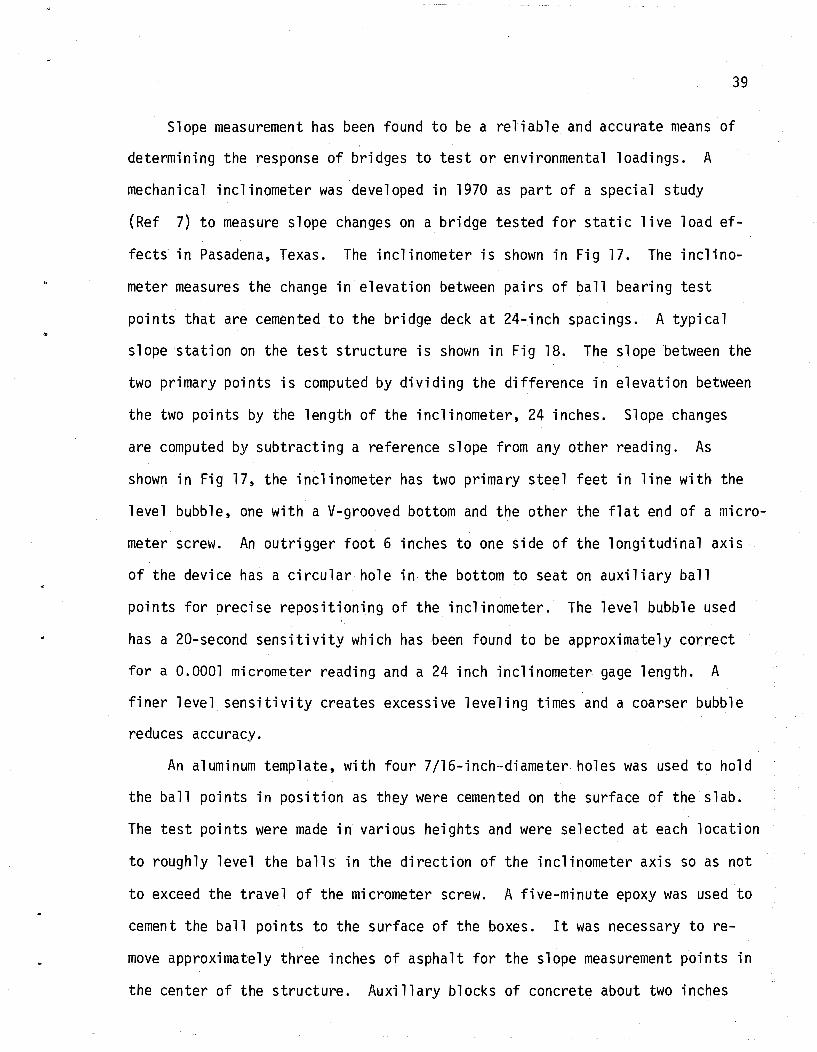
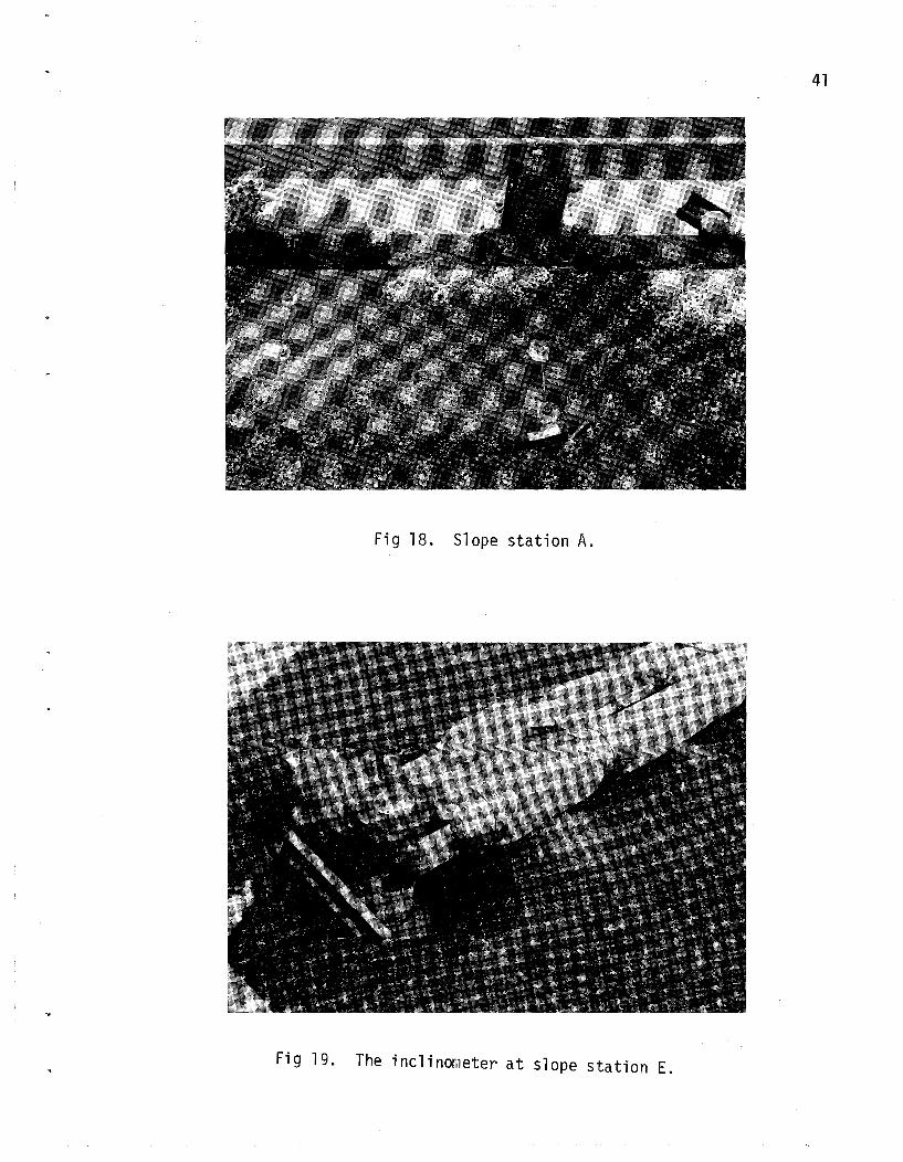
points that are cemented to the bridge deck at 24-inch spacings. A typical
slope station on the test structure is shown in Fig 18. The slope between the
two primary points is computed by dividing the difference in elevation between
the two points by the length of the inclinometer, 24 inches. Slope changes
are computed by subtracting a reference slope from any other reading. As
shown in Fig 17, the inclinometer has two primary steel feet in line with the
level bubble, one with a V-grooved bottom and the other the flat end of a micro
meter screw. An outrigger foot 6 inches to one side of the longitudinal axis
of the device has a circular hole in the bottom to seat on auxiliary ball
points for precise repositioning of the inclinometer. The level bubble used
has a 20-second sensitivity which has been found to be approximately correct
for a 0.0001 micrometer reading and a 24 inch inclinometer gage length. A
finer level sensitivity creates excessive leveling times and a coarser bubble
reduces accuracy.
An aluminum template, with four 7/16-inch-diameter holes was used to hold
the ball points in position as they were cemented on the surface of the slab.
The test points were made in various heights and were selected at each location
to roughly level the balls in the direction of the inclinometer axis so as not
to exceed the travel of the micrometer screw. A five-minute epoxy was used to
cement the ball points to the surface of the boxes. It was necessary to re
move approximately three inches of asphalt for the slope measurement points in
the center of the structure. Auxillary blocks of concrete about two inches

40
~------------------24 in.------------------~~~I
20- Second Level Bubble
Adjustable Foot (Steel) ~~~===============~====:=;;z!===n
f
4 in. Wide Channel ( Aluminum)
(a) Inclinometer .
..... --0.75 in. dio---'"'1
.15 in.
~#'w/'4---y-.05 in.
(b) Ball point.
--""-- Countersunk Mount Screws
Adjustable (Steel) Lateral Support
Hole
Bridge Deck
Fig 17. Slope measuring instrument and test point (Ref 7).
41
Fig 18. Slope station A.
Fig 19. The inclinometer at slope station E.

42
high were cemented on the boxes prior to placement of the ball points to bring
them above the surrounding asphalt level. One of the center stations is
shown in Fig 19.
Data Recording
Each slope observation was taken with two readings of the micrometer
screw, with the inclinometer reversed end-for-end between the two readings.
This procedure serves to cancel instrument errors as well as to provide the
possibility of self-checking the readings in the field. Only instrument errors
that occur between the two readings are not canceled by this procedure. The
inclinometer (insulated to retard sudden temperature changes) is shown in Fig
19 for the direct reading at Station E. Data from the inclinometer readings
is summarized in Appendix A for each slope station. The inclinometer was
shaded by an umbrella at all times.
A form for recording the inclinometer readings and a typical numerical
example. are shown in the table below. Regardless of the slope station or re
lative ball pOint elevations, the sum of any direct and reverse readings re
mains almost constant. Any significant variation was used as a basis for an
immediate re-check of the slope readings.
Slope Station Time Direct (in)
Reverse (in)
Sum -2 x Reverse =2 x Diff Elev
A 11 : 1 0 .5750 .0128 .9500 .0111
1.5489 -1.9222 -0.3733
Direct readings were taken with the micrometer screw seated at the north
reference points with the reverse readings at the south reference pOints. The

43
two entries for each direct and reverse reading are the two readings made of
the micrometer screw. The first is the coarse reading of the screw barrel
which has 0.025 inch divisions. The second is the vernier reading to 0.0001
inch divisions. This procedure eliminated the need to make a mental addition
in the field and thus many errors were avoided. The sum of all four readings
was performed in the field, and as can be seen in Appendix A, the sums remained
almost constant at 1.55. The slight variation in sums is thought to be due to
a gradual heating of the inclinometer through the test day with a shift occur
r-ing after noon due to mishandling. The actual elevation differences are still
considered accurate to about 0.0002 inch. Any error from temperature or mis
handling would have had to occur between the direct and reverse readings; this
would have been immediately apparent resulting in a new set of readings.
Sunmary of Measurements
Six slope stations were located on the second span of the test structure.
Each station had four measurement points of which two were the primary points
and tW3 the outrigger points for re-positioning purposes. The points were ce
mented near the ends of the two outside boxes and the centerline box. The.pri
mary points were located on the box centerlines at 12 inches and 36 inches from
the bent centerline as shown in Fig 16.
Plots of the differences in elevation for the six slope stations are shown
in Fi gs 20 and 21. The soli d l·j ne between poi nts shows the change in the slope
readings as heating of the top surface took place. This line was then the no
load reference. The dashed lines connect the slope readings taken with each of
the three load positions (Fig 16). As can be seen, the response was almost
antisymmetrical; that is, the slopes for Station A were like those for Station
F, Station B was like E, and C was similar to D. Much greater slope changes
occurred in the exterior boxes with the exterior loadings that for the center
box with center loading. This does not imply that the exterior boxes should

A
1\ 44 I \ I \
,- .3700 I I I 1/+' 1 I 1 800 900 1000 I \ 1200 1300 1400
Time (eDT) I \ I \ I \ 1 \
-.380 I \ I
I \
I \
Station A I \ \
-.390 I \ I \ - I
rfl CD
.£! u s:!
-r-! .030 + <d' N A H Ldg1
I \ + CD I \ 0. I I rfl I \ CD .020 I \ 'fi I \ 1\ s:! I \ I
I \ .r-! \ ...... + I
\ / / \
:> Station B " ....... , I \ " -... \ CD
,. , r-l .010
\ CD
s:! ~ -r-!
~\ ~ ~ 4-1 I I I -r-! \
~ - .140 I \ ,
\ Ldg2 Ldg3 :5 I \ I I I \ CD I u \ -r-! I \ + Computer Results ~ 8 I \
-.150 I \ • Field Measurements I \ I \ + I \ I \ Station C \ ... "\ -.160 ./ \ ./
./ \ \
\
-.170
Fig 20. Slope readings at south support.

.060 I I I I I I 800 900 1000 1100 1300 1400
'l'ime (CDT) / I --- / \ / / I + '\.
/ \ '\. '\. /
\ I .050 Station D 'v / \ I \ I
+ \ I \ / - \ I
~.040
I t \ I ..c: \ I 0 s::
Ldg1 Ldg2 \ I -..-I
I I \ I «:t' I N \
~.0300 W P.! \ I
CJ) ~ (!)
..c: 0 s::
• ..-1 -- \ :>.2200 Station E \ / \ .... ......
\ / \ / ....... --(!)
+ .-! \ / \ / (!) \ / \ / s:: \ / \ / • ..-1 V \ / lH \ / I lH.2100
-r-! \ / "d + \ / Ldg3 (!) V I i1 + (!) 0
• ..-1
~.2300
\ I Station F \ I
+Computer Results· \ I
.2200 \ I \ I • Field Measurements \ I \ I \ I
.210 \ I \ I
I
\ l\f ~
Fig 21. Slope readings at north support.

46
be designed for more load. Had two or three trucks been placed on the struc
ture, then the maximum response of each box would be more nearly the same.
computer Analysis Comparisons
Program SLBDG 2 was used to analyze the structure after the test to deter
mine if the measured values could be predicted analytically. As can be seen
in Figs 20 and 21, the computer values are in generally good agreement with the
measured slopes. The computed slopes are about 15 percent less than the mea
sured for the outside boxes with outside loadings and about 10 percent more
for the center box with center loading. A number of computer solutions were
made with various assumptions for concrete modulus of elasticity and trans
verse bending stiffnesses. It was found that a concrete modulus of about 6200
ksi gave the closest average match between measured and calculated. A zero
shear key stiffness factor was also found to be the best model. It is hypo
thesized however, that due to the general heating of the structure, the central
boxes may tend to prestress themselves together across the shear keys thus
giving more distribution for the center boxes than for the outside boxes. It
is impossible at this time to validate this hypothesis, but it seems reasonable
in view of the smaller measured center box slopes.
The concrete used for the box beams had been tested at time of release
and at 14 days. This data ;s listed in Appendix A. The average concrete
strength at 14 days was approximately 7000 psi. Based on this, a concrete
strength in excess of 8000 psi can be estimated to be present at the time of
test loading. This strength correlates well with the concrete modulus of 6200
ksi which was used to obtain the computed results.

47
CHAPTER 7. CONCLUSIONS AND RECOMMENDATIONS
The problem of accurate design of skewed multi-beam structures is greatly
complicated when the spans are skewed. The primary object of this study was
to determine the appropriate design bending moments for multi-beam precast
box members of the types currently in use in Texas.
Providing design charts and tabulations for all the variations of box
width, skew, structure width, structure span, and individual structural vari
ations such as twisting stiffness and transverse shear key stiffness was not
economically justified. Development of such tabulations is possible, but it
was found during the course of the project, that use of the developed data
generator computer program was quite simple and it could be easily applied to
specific design cases.
Verification of Analysis Methods
The analysis technique has been adequately verified by comparisons to other
methods and to various field and laboratory tests bya number of investigators.
A field test of a full-scale skewed structure was performed on this project
and provided exceptionally good correlations between predicted and measured
response. This correlation adds significant confidence to the user of the de
vel oped analysis technique.
Impact on Construction Costs
It has been demonstrated that a significant reduction in design live load
bending moment can be expected by considering the skew angle and span aspect
ratio for precast box beam bridges of the type currently in use in Texas. The
reduction will vary from about 10 per cent for rectangular structures to about
50 percent for heavily skewed structures. The design live load reduction results
in requiring fewer prestressing strands or allowing the maximum span length to be

48
increased for a particular box size. T,his second effect has a much greater
impact on costs since the strand cost differential is usually small. Reducing
the box size by one increment will usually reduce the cost in the range of
$1.00 to $3.00 per square foot of structure. For instance, a 70 foot span
square structure woul d requi re 28 inch deep boxes while the same span skewed
45 degrees woul d only require 20 inch deep boxes for the same concrete strengths.
The final conclusion and result of this project is to recommend that the
SLBDG 2 computer program (which is essentially a data generator for the SLAB
49 program) be used for future design of skewed multi-beam box structures in
Texas. It should also be used for more accurate analysis of these structures
when subjected to planned overloads.

REFERENCES
1. A1ani, A. F., and John E. Breen, "Verification of Computer Simulation Methods for Slab and Girder Bridge Systems," Research Report No. ll5-1F t Center for Highway Research, The University of Texas at Austin, August 1971.
2. The American Association of State Highway Officials, !!Interim Specifications, Bridges," Washington, D.C., 1974.
3. The American Association of State Highway Officials, Standard Specifications for Highway Bridges, Ninth Edition, 1965.
4. The American Association of State Highway Officials, Standard Specifications for Highway Bridges, Eighth Edition, 1961.
5. Chen, T. Y., C. P. Siess, and N. W. Newmark, "r~oments in S'imply Supported Skew I-Beam Bridges,!! University of Illinois Engineering Experiment Station, Bulletin 439, January 1957.
6. Kennedy, John B., and D.S.R. Gupta, "Bending of Skew Orthotropic Plate Structures," ASCE Structural Journal, Vol 102, No ST8, August 1976.
7. ~1at10ck, Hudson, J. J. Panak, r1. R. Vora, and J. H. C. Chan,IIField Investigation of a Skewed, Post-Stressed Continuous Slab Structure:' Unpublished Interim Study Report to Texas Highway Department Bridge Division, Center for Highway Research, The University of Texas at Austin, May 1970.
8. Panak, John J., and Hudson Matlock, IIA Discrete-Element r~ethod of Analysis for Orthogonal Slab and Grid Bridge Floor Systems," Research Report No 56-25, Center for Highway Research, The University of Texas at Austin, May 1972.
9. Panak, John J., "Final Report for Project 3-5-63-56,11 Research Report No. 56-29F, Center for Highway Research, The University of Texas at Austin, August 1973.
10. Sanders, W. l·J. Jr., and H. A. Elleby, "Distribution of \~heel Loads on Highway Bridges," NCHRP Report 83, Highway Research Board, 1970.
11. Vora, M. R., and Hudson 1~1atlock, "A Discrete-Element Analysis for Anisotropic Skew Plates and Grids," Research Report No. 56-18, Center for Highway Research, The University of Texas at Austin, August 1970.
12. 14atanabe, Eiichi, "Study of Load Distribution in r~ulti-Beam Highway Bridges'" Master's Thesis, Iowa State University, Ames, 1968.
13. Will, Kenneth M., C. P. Johnson, and H. f\1atlock, "Ana1ytica1 and Experimental Investigation of the Thermal Response of Highway Bridges," Preliminary Research Report No. 23-2, Center for Highway Research, The Uni versity of Texas at Austi n, February 1977.
49

APPENDIX A
FIELD TEST LOAD DATA

51
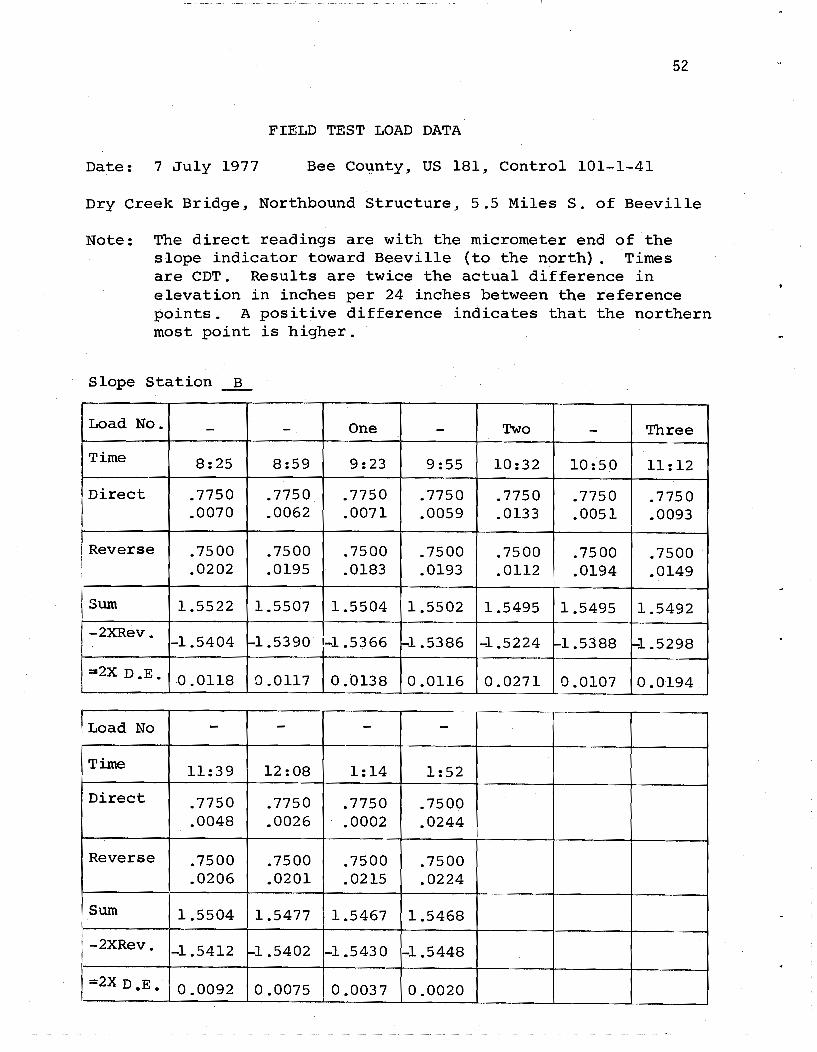
FIELD TEST LOAD DATA
Date: 7 July 1977 Bee County, US 181, Control 101-1-41
Dry Creek Bridge, Northbound structure, 5.5 MilesS. of Beeville
Note: The direct readings are with the micrometer end of the slope indicator toward Beeville (to the north). Times are CDT. Results are twice the actual difference in elevation in inches per 24 inches between the reference points. A positive difference indicates that the northern most point is higher.
Slope Station A
Load No. - - One - Two - Three
Time 7:41 8:57 9:21 9:51 10:28 10:48 11:10
Direct .5750 .5750 .5500 .5500 .5500 .5500 .5750 .0016 .0005 .0243 .0232 .0230 .0215 .0128
Reverse .9500 .9500 .9750 .9750 .9750 .9750 .9500 .0246 .0248 .0003 .0011 .0010 .0020 .0111
Sum 1.5512 1.5503 1.5496 1.5493 1.5490 1.5485 1.5489
-2XRev. -1.9492 -1.9496 -1.9506 -1.9522 -1.9520 -1.9540 -1.9222
=2X D. E. -0.3980 -0.3993 -0.4010 -0.4029 -0.4030 -0.4055 -0.3733
Load No - - - -Time 11:35 12 :05 1:10 1:51
Direct .5500 .5500 .5500 .5500 .0218 .0192 .0177 .0164
Reverse .9750 .9750 .9750 .9750 .0026 .0022 .0045 .0051
Sum 1.5494 1.5464 1.5472 1.5465
-2XRev. -1.9552 -1.9544 -1.9590 -1.9602 I
=2X D.E. -0.4058 -0.4080 -0.4118 -0.4137
52
FIELD TEST LOAD DATA
Date: 7 July 1977 Bee Co~nty, US 181, Control 101-1-41
Dry Creek Bridge, Northbound Structure, 5.5 Miles S. of Beeville
Note: The direct readings are with the micrometer end of the slope indicator toward Beeville (to the north). Times are CDT. Results are twice the actual difference in elevation in inches per 24 inches between the reference points. A positive difference indicates that the northern most point is higher.
Slope Station ~
Load No. - - One - Two - Three
Time 8:25 8:59 9:23 9:55 10:32 10:50 11:12
Direct .7750 .7750 .7750 .7750 .7750 .7750 .7750 .0070 .0062 .0071 .0059 .0133 .0051 .0093
Reverse .7500 .7500 .7500 .7500 .7500 .7500 .7500 . .0202 . 0195 .0183 .0193 .0112 .0194 .0149
!.
!sum 1.5522 1.5507 1.5504 1.5502 1.5495 1.5495 1.5492
-2XRev. -1.5404 ro-l.5390 1-1.5366 1-1.5386 -1.5224 :...1.5388 -1.5298
:a2X D.E. 0.0118 0.0117 0.0138 0.0116 0.0271 0.0107 0.0194
..
Load No - - - -Time 11:39 12:08 1:14 1:52
Direct .7750 .7750 .7750 .7500 .0048 .0026 .0002 .0244
• Reverse .7500 .7500 .7500 .7500 .0206 .0201 .0215 .0224
Sum 1.5504 1.5477 1.5467 1.5468
-2XRev. -1.5412 t-1.5402 -1.5430 -1.5448
=2X D.E. 0.0092 0.0075 0.0037 0.0020

53
FIELD TEST LOAD DATA
Date: 7 July 1977 Bee County, US 181, Control 101-1-41
Dry Creek Bridge, Northbound Structure, 5.5 Miles S. of Beeville
Note: The direct readings are with the micrometer end of the slope indicator toward Beeville (to the north). Times are CDT. Results are twice the actual difference in elevation in inches per 24 inches between the reference points. A positive difference indicates that the northern most point is higher.
Slope Station C
Load No. - - One - Two - -Time 7:39 9:03 9:25 9:57 10:38 10:52 10:57
Direct .6750 .6750 .7000 .6750 .6750 .6750 .6750 .0211 .0197 .0105 .0192 .0208 .0171 .0174
Reverse .8500 .8500 .8250 .8500 .8500 .8500 .8500 .0059 .0066 .0168 .0062 .0044 .0077 .0078
Sum 1.5520 1.5513 1.5523 1.5504 1.5502 1.5498 1.5502
-2XRev. -1.7118 -1.7132 ..;J. .6836 ,...1.7124 -1.7088 -1.7154 :-1.7156
"""2X_D.E. 1-0.1598 -0.1619 !-O .1313 rO .1620 ~ .1586 kJ .1656 -0.1654
Load No Three - - - -Time 11:15 11:41 12:10 1:16 1:55
Direct .6750 .6750 .6750 .6750 .6750 .0171 .0160 .0140 .0117 .0106
Reverse .8500 .8500 .8500 .8500 .8500 .0080 .0092 .0094 .0110 .0118
Sum J... 550 1 1.5502 1.5484 1.5477 1.5474
-2XRev. -1.7160 -1.7184 -1.7188 1.7220 -1.7236
=2X D.E. f-o .1659 kJ .1682 !-O .1704 !-O .1743 Lo.1762

54
FIELD TEST LOAD DATA
Date: 7 July 1977 Bee county, US 181, Control 101-1-41
Dry Creek Bridge, Northbound Structure, 5.5 Miles S. of Beeville
Note: The direct readings are with the micrometer end of the slope indicator toward Beeville (to the north). Times are CDT. Results are twice the actual difference in elevation in inches per 24 inches between the reference points. A positive difference indicates that the northern most point is higher.
Slope Station ~
Load No. - - One - - Two Two
Time 7:44 8:55 9:19 9 :43 9:47 10:21 10:24
Direct .8000 .8000 .8000 .8000 .8000 .7750 .7750 .0017 .0020 .0031 .0024 .0023 .0237 .0237
Reverse .7500 .7250 .7250 .7250 .7250 .7500 .7500 .0003 .0241 .0237 .0227 .0229 .0000 .0001
Sum 1.5520 1.5511 1.5518 1.5501 1.5502 1.5487 1.5488
-2XRev. ~1.5006 r-1.4982 1-1.4974 1-1.4954 -1.4958 1-1.5000 1-1.5002
=2X D.E. 0.0514 0.0529 0.0544 0.0547 0.0544 0.0487 0.0486
Load No - Three - - - -Time 11:00 11:24 11:49 12:19 1:23 2:01
Direct .8000 .7750 .8000 .8000 .8000 .8000 .0032 .0124 .0032 .0038 .0047 .0061
Reverse .7250 .7500 .7250 .7250 .7250 .7250 .0214 .0118 .0212 .0197 .0176 .0165
. Sum 1.5496 1.5492 1.5494 1.5485 1.5473 1.5476
-2XRev. ~1.4928 1-1.5236 -1.4924 -1.4894 -1.4852 -1.4830 , =2X D.E. 0.0568 0.0256 0.0570 0.0591 0.0621 0.0646

55
FIELD TEST LOAD DATA
Date: 7 July 1977 Bee County, US 181, Control 101-1-41
Dry Creek Bridge, Northbound Structure, 5.5 Miles S. 6f Beeville
Note: The direct readings are with the micrometer end of the slope indicator toward Beeville (to the north). Times are CDT. Results are twice the actual difference in elevation in inches per 24 inches between the reference points. A positive difference indicates that the northern most point is higher.
Slope Station E
Load No. - - One - Two - Three
Time 8:21 8:52 9:16 9:40 10:17 10:58 11:22
Direct .8750 .8750 .8750 .8750 .8750 .8750 .8750 .0112 .0110 .0062 .0103 .0023 .0095 .0084
Reverse .6500 .6500 .6500 .6500 .6500 .6500 .6500 .0144 .0138 .0185 . .0140 .0214 .0144 .0150
Sum 1.5506 1.5498 1.5497 1.5493 1.5487 1.5489 1.5484
-2XRev. -1.3288 -1.3276 -1.3370 -1.3280 -1.3428 -1.3288 -1.3300
""'2X D.E. 0.2218 0.2222 0.2127 0.2213 0.2059 0.2201 0.2184
Load No - - - -Time 11:47 12:15 1:21 1:59
Direct .8750 .8750 .8750 .8750 .0091 .0091 .0096 .0108
Reverse .6500 .6500 .6500 .6500 .0145 .0127 .0112 .0109
Sum 1.5486 1.5468 1.5458 1.5467
-2XRev. -1.3290 -1.3254 -1.3224 -1.3218
=2X D.E. 0.2196 0.2214 0.2234 0.2249

56
FIELD TEST LOAD DATA
Date: 7 July 1977 Bee County, US 181, Control 101-1-41.
Dry Creek Bridge, Northbound Structure, 5.5 Miles S. of Beeville
Note: The direct readings are with the micrometer end of the slope indicator toward Beeville (to the north). Times are CDT. Results are twice the actual difference in elevation in inches per 24 inches between the reference points. A positive difference indicates that the northern most point is higher.
Slope Station F
Load No. - - One - Two - Three
Time 7:35 8:48 9:13 9:37 10:13 10:55 11:19
Direct .8750 .8750 .8750 .8750 .8750 '.8750 .8750 .0128 .0135 .0015 .0135 .0132 .0145 .0144
Reverse .6500 .6500 .6500 .6500 .6500 .6500 .6500 .0140 .0127 .0249 .0123 .0120 .0112 .0111
Sum 1.5518 1.5512 1.5514 1.5508 1.5502 1.5507 1.5505
-2XRev. -1.3280 -1.3254 -1.3498 -1.3246 -1.3240 -1.3224 -1.3222
=2X D.E. 0.2238 0.2258 0.2016 0.2262 0.2262 0.2283 0.2283
Load No - - - -Time 11:44 12:13 1:19 1:57
Direct .8750 .8750 .8750 .8750 .0147 .0141 .0151 .0154
Reverse .6500 .6500 .6500 .6500 .0105 .0095 .0076 .0074
Sum 1.5502 1.5486 1.5477 1.5478
-2XRev. -1.3210 -1.3190 -1.3152 -1.3148
=2X·D.E. 0.2292 0.2296 0.2325 0.2330
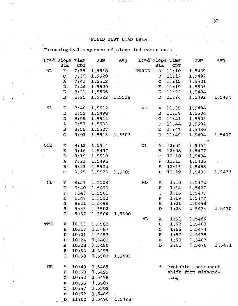
57
FIELD TEST LOAD DATA
Chronological sequence of slope indicator sums
Load Slope Time Sum Avg Load Slope Time Sum Avg Sta eDT Sta eDT
NL F 7:35 1.5518 THREE A 11:10 1.5489 e 7:39 1.5520 B 11:12 1.5492 A 7:41 1.5512 e 11:15 1.5501 D 7:44 1.5520 F 11:19 1.5505 E 8:21 1.5506 E 11:22 1.5484 B 8:25 1.5522 1.5516 D 11:24 1.5492 1.5494
NL F 8:48 1.5512 NL A 11:35 1.5494 E 8:52 1.5498 B 11:39 1.5504 D 8:55 1.5511 e 11:41 1.5502 A 8:57 1.5503 F 11:44 1.5502 B 8:59 1.5507 E 11:47 1.5486 e 9:03 1.5513 1.5507 D 11:49 1.5494 1.5497
* ONE F 9:13 1.5514 NL A 12:05 1.5464 E 9:16 1.5497 B 12:08 1.5477 D 9:19 1.5518 e 12:10 1.5484 A 9:21 1.5496 F 12 :13 1.5486 B 9:23 1.5504 E 12:15 1.5468 e 9:25 1.5523 1.5509 D 12:19 1.5485 1.5477
NL F 9:37 1.5508 NL A 1:10 1.5472 E 9:40 1.5493 B 1:14 1.5467 D 9:43 1.5501 e 1:16 1.5477 D 9:47 1.5502 F 1:19 1.5477 A 9:51 1.5493 E 1:21 1.5458 B 9:55 1.5502 D 1:23 1.5473 1.5470 e 9:57 1.5504 1.5500
NL A 1 :51 1.5465 TWO F 10:13 1.5502 B 1:52 1.5468
E 10:17 1.5487 e 1:55 1.5474 D 10:21 1.5487 F 1:57 1.5478 D 10:24 1.5488 E 1:59 1.5467 A 10:28 1.5490 D 2,:01 1.5476 1.5471 B 10:32 1.5495 e 10:38 1.5502 1.5493
NL A 10:48 1.5485 * Probable instrument B 10:50 1.5495 shift from mishand-e 10:52 1.5498 ling F 10:55 1.5507 e 10:57 1.5502 E 10:58 1.5489 D 11:00 1.5496 1.5498

58
FIELD TEST LOAD DATA
Date: 7 July 1977 Bee County, US 181, Control 101-1-41
Dry Creek Bridge, Northbound Structure, 5.5 Miles S. of Beeville
At Station E Bottom
Time Temp (OF) Time
0847 90 0847 0915 92 0939 93 0939 1012 94 1012 1058 98 1122 100 1146 102 1143 1214 103 1222 1320 108 1324 1358 108
of Structure
Temp (OF)
87
89 88
91 93 96
Wind
None
Approx Approx Approx
5 mph 10 mph
20 r from SE from SE from S
Approx 20 mph from S
The structure was in tree shade until about 0800 hours. Small clouds periodically shaded the bridge not more than 5 percent of the time.
Shade Air temperature at 1340 hours was 97°.
The temperature at Station E was within the asphalt excavation for the ball points (See Figure 19) which was shaded continuously by a cardboard covering except when inclinometer readings were made.
The temperature at the bottom was taken with a thermometer taped to the bottom surface near the SE corner of the structure.

59
FIELD TEST LOAD DATA
Date: 7 July 1977 Bee County, US 181, Control 101-1-41
Dry Creek Bridge, Northbound Structure, 5.5 Miles S. of Beeville
Second span casting records were obtained from the Materials and Test Division of DHT with the fo11ow.ing results.
Casting
Fri Sept Tues Sept Wed Sept Fri Sept
Date No.' Boxes Release Strength 14 Day Strength and Type (psi) (psi)
5, 1975 4 interior 4218 @ 18.Hrs 9, 1975 4 interior 5429 @ 46 Hrs 10, 1975 1 exterior 4987 @ 30 Hrs 12, 1975 1 interior & 4916 @ 62 Hrs
1 exterior
Average of 11 Boxes: 4855 psi @ release 6892 psi @ 14 days
Required Design Strengths: 4000 psi @ release 5000 psi @ 28 days
6012 7459 7068 7432

APPENDIX B
GUIDE FOR DATA INPUT
PROGRAM SLBDG 2

Page 1 of 10
SKEWED MULTI-BEAM BRIDGE ANALYSIS - SLBDG 2
This program acts as a data generator for the SLAB49 program and should be used for the analysis of multi-beam bridges composed of prestressed box cross-sections. It is especially useful for skewed structures since the live load design moment is significantly less than for square structures. The spans are assumed simply supported along the skewed support. Square structures may also be analyzed.
IDENTIFICATION OF RUN (two cards per run)
These first two cards identify the run. The Problem Series File No. (PSF No.) is for data filing purposes. The first card indicates the recommended information that should be included to identify the run; however, the complete card may be used for any descriptive data as indicated by the dashed lines. A consistent system of units must be used for all input data. Kips and inches are usually the most convenient.
Problem PDf Coded Units Series
File No. County Hwy No. IPE Control-Sec-Job By Date Force· - Length r-- 1--1 I -I 1--1 1 1 1 -[~- 1 1- I 1
5 8 20 23 28 3' 34 37 47 50 52 55 66 69 80
Structure Name or other descriptive run information (do not leave blank)
80
Check to ensure that each run has the above two header cards and that each problem in the run (which may encompass a series of problems) has a Prob No. card as follows. Each individual problem in the run may have any convenient descriptive Prob No. such as LDG 5. A final card iU,,-the run with CEASE as the Prob No. indicates the end of the data.
IDENTIFICATION OF PROBLEM (one card each problem) 0'\
Prob No. Description of problem
1 I I
I' 5 II 801

Page 2 of 10
Each page in this input guide is for a specific data table. If the blank general coding forms are used, which match the spacing on these forms, then each page can be placed over or adjacent to the blank form to act as the input heading for each data table.
All integer numbers must be right justified if in a 2 space field. All 5 or 10 space fields may be entered at the user's convenience. For example -123.4 or -1.234E+02 define the same number; a d.ecimal point must be used. Blanks are interpreted as zeros.
TABLE 1. CONTROL DATA (two cards for each problem)
Any data may be kept from a prior problem unless if the problems are within a Parent-Offspring series. An Offspring problem must hold Tables 2, 3, and 4 from the previous problem. Tables 5, 7, or 8 may also be kept if desired. A new Table 6 is required for each Offspring problem.
The multiple-load option may be blank or zero in which case the problem is assumed to be independent with only a single load condition. A Parent problem is specified by entering a +1. An Offspring problem is specified by entering a -1. Specification of a Parent problem implies that there are 1 or more following Offspring problems for exactly the same span with different load patterns or placements.
The complete generated SLAB49 data may be printed if desired by entering a 1 for the option.
The skew angle is the angle between a perpendicular to the longitudinal centerline and. the support centerline. A left forward skew is positive.
Multiple Enter 1 to Enter 1 to keep data from prior TABLE Load Print SLAB49
2 3 4 5 6 7 8 9 Option Generated Data n n __ D~ D D D D TI D 5 10 15 20 25 30 35 40 50 75
Number of cards added for TABLE Skew Angle 2 3 4 5 6 7 8 9 Degrees n __ [] n [J Il---,-D~-,--D--,----,--D-,--__ ,,---_--,-5 10 15 20 25 '30 35 40 51 60
0"1 N

Page 3 of 10
TABLE 2. CONSTANTS (one card - none if kept)
This table must be omitted for Offspring problems.
The number of increments are the totals along the span from c-c of assumed bearing and out to out transversely. A skewed span has the same input number of span X increments as a square span with the same increment length. The generated SLAB49 model will have more X increments for the skewed span however.
The increment lengths may be any fractional length. They should be chosen so there is at least 4 to 5 increments transversely in each box beam and 12 to 14 increments in the span.
Poisson's Ratio is usually specified equal to 0.15 or 0.20 for concrete.
The Modulus of Elasticity may be any conventional value for concrete such as 5000 kips per inch. The modulus only affects the computed deflections.
No. of Increment Lengths Poisson's Modulus of Increments X-Direction Y-Direction Ratio Elasticity X Y hx hy E n n [ I
5 10 21 30 40 50 60
0)
w

Page 4 of 10
TABLE 3. BOX STIFFNESS DATA (one card each type - none if kept)
This table must be omitted for Offspring problems.
The different box types used to make up the structure are input with this table beginning with type 1. Up to 10 types may be used.
The number of transverse Y increments used for each box defines the total box width. Therefore, this table must be consistent with the transverse increment length used in Table 1 and the box arrangement specified in Table 4.
The box depth, internal void width, and top and bottom slab thicknesses are input in F5.0 format. That is, a 5 inch slab may be entered as a right justified 5 or as 5.0. The decimal form is reconunended. Solid cross-sections may be input by specifying a 0.0 void width and 0.0 slab thick.· nesses. A inverted. U cross-section could also be input by specifying the void width as the distance between the webs with only a top slab.
The shear key stiffness factor is used to define the degree of remaining transverse stiffness at the shear key between beams. A value of 0.0 is usually best. A solid slab (not articulated) could be solved with a key stiffness factor of 1.0.
The longitudinal moment of inertia is the conventional total value computed about the horizontal neutral axis of the box. The torsional inertia is the value usually known as the St. Venant torsion constant and may be estimated for a box cross-section by the following formula taken from Ref 4.
4 (lh lu) 2 J =
2lv + lh (tt + tb tw tt t b
where lh is the width between web centers, Iv is the depth between slab centers and tw, tt' and tb are web, top, and bottom slab thicknesses.
Type Increments Box Void . Top No. in width Depth Width Slab
n D I I I I 5 10 16 20 25 30
Bot Slab
35
Shear Key Stiffness
Factor
41 45 51
Moment Torsional Inertia Inertia
60 70
C'I .j:::>
I .
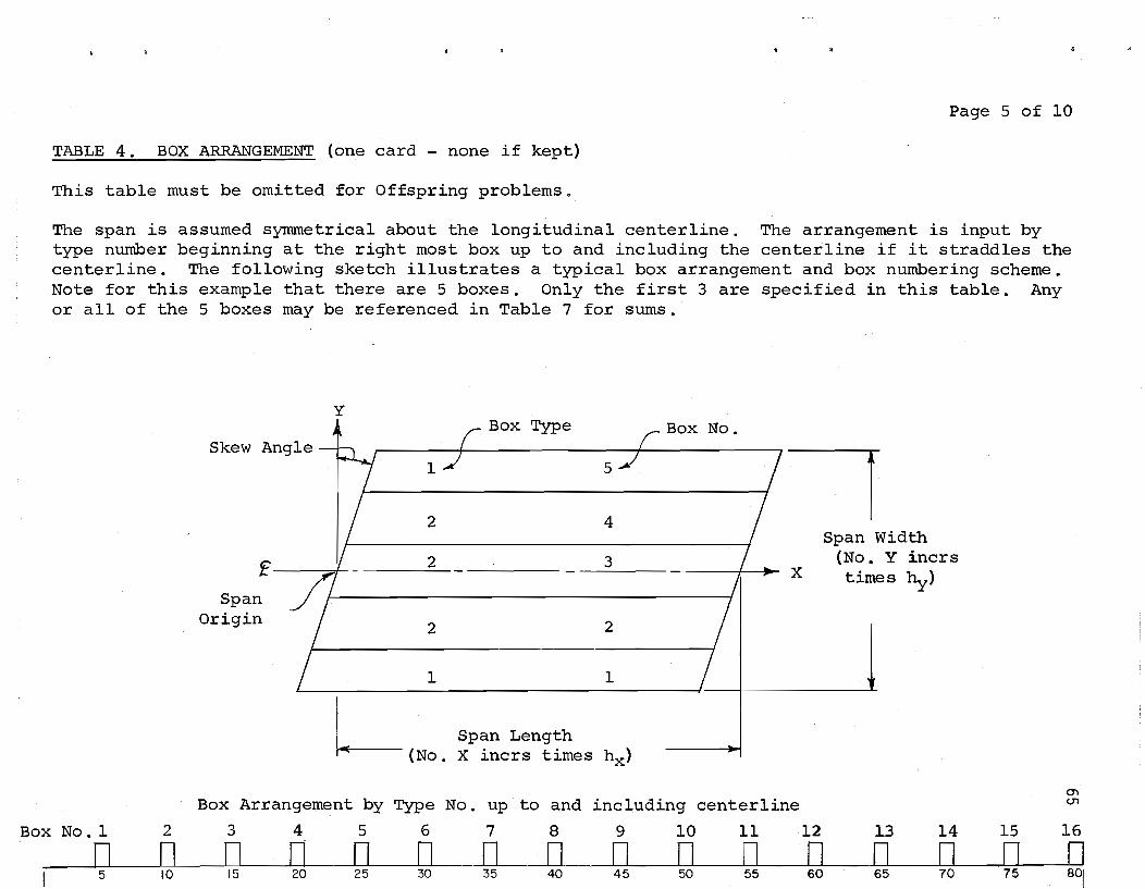
Page 5 of 10
TABLE 4. BOX ARRANGEMENT (one card - none if kept)
This table must be omitted for Offspring problems.
The span is assumed symmetrical about the longitudinal centerline. The arrangement is input by type number beginning at the right most box up to and including the centerline if it straddles the centerline. The following sketch illustrates a typical box arrangement and box numbering scheme. Note for this example that there are 5 boxes. Only the first 3 are specified in this table. Any or all of the 5 boxes may be referenced in Table 7 for sums.
y
Skew Angle
f I ::=:;0;:,
Span Origin
2
2
2
1
L(No,
Box Type
5
4
3
2
1
Span Length X incrs times h x )
Box No.
---r X
Span width (No. Y incrs times by)
.~
Box Arrangement by Type No. up to and including centerline
Box No.1 2 3 4 5 6 7 8 9 10 11 12 13 14 15
0"1 <.T1
16
n D n n n D D n n n n n n n ~ 0 5 10 15 20 25 30 35 40 45 50 55 60 65 70 75 801

(two
This input or dif , kept from problem to with
Page 6 of
pa.ttern - none if kept)
problems. For a series of Offspring problems with ipated patterns may be input in the Parent problem and
ired patterns used by the Table 6 placements 5
Each pattern is identified by a number (beginning with 1) up to a maximum of 10 different patterns. Each pattern may have from 1 to 6 loads. If the desired pattern has more than 6 loads, then multiple patterns may be specified which can be overlapped by the Table 6 placements.
Each load in the pattern is referenced to a local pattern coordinate system the origin of which may be one of the loads or any other convenient point. This local pattern reference point is the point by which the pattern is placed by Table 6. An example is shown below ..
The coordinate distances are input in FS.O format and may be negative.
Negative loads are downward.
y
o 7 Loads
o
x
o y
k ~x
Point
No. Pattern of These decimal distances are from the load pattern reference point
No . Loads x Y x Y x Y x . Y x Y x Y
o IL I I I I I I I 5 10 15 20 25 Magni tude 0 f Loads 45 50 55 60 65 70
I I I I I._.~ __ l_ I II 20 30 40 50 60 70
0'1 0'1

Page 7 of 10
TABLE 6. PLACEMENTS OF LOAD PATTERNS (maximum of 10 cards - none if kept)
This table may not be kept for Offspring problems. Each offspring problem must have a new Table 6.
Each pattern may be placed at as many as 6 different locations on the span. This allows for instance, definition of one truck pattern by Table 5 with up to 6 like trucks placed simultaneously.
The placement is by pattern number and coordinate distances. The distances are in reference to the span geometry wherein the intersection of the longitudinal centerline and the first support line is considered to be the span origin. This is shown in the sketch on page 5.
No. of
P1ace-0) '-I

Page B of 10
TABLE 7. SUMMATION OF BOX BENDING MOMENTS (maximum of 10 cards - none if kept)
This table may be kept for any type of problem or input for each problem.
The locations at which the longitudinal box bending moments will be summed are defined by this table. The summations are the total bending moment in the box and may be used directly for design p~rposes.
Sums may be for any or all boxes within the span. For instance, if the span has 5 boxes as in the sketch on page 5, the first 3 were specified by Table 4 but any of the 5 boxes may be summed. Any location along the span of the box may be summed.
Distances to the summation locations are in reference to the span coordinate system as shown on page 5.
No. Box of Sum moments at these decimal X- distances from the span or~g~n No. Sums X X X X X X
o II I I I I ~t 5 10 20 30 40 50 60 70

Page 9 of 10
TABLE 8. PROFILE OUTPUT AREAS (maximum of 10 cards - none if kept)
This table may be kept for any type of problem or input for each problem.
Profile output is helpful in displaying the variation of deflections or moments along a beam line or transversely across the span. Deflection, bending moment in the X or Y direction, and maximum principal moment may be displayed. The profiles are presented in the form of crude printer plots for each area specified. The plots have a width of 20 print characters. Each plot has no scale or zero reference. The values are relative to one another, increasing positively to the right.
The profile output area limits are those SLAB49 stations which are nearest these input values of from and thru distance coordinates. The coordinates are with reference to the span origin.
Distances are input in F5.0 format. Thus 12345 is interpreted as 12345.0 and 12.34 is interpreted as input.
Enter 1 for From Thru Principal The from and thru decimal distances
X Y X Y Defl X-Mom Y-Mom Moment refer to the span origin.
I 0 ODD ~ I' 5 10 15 20 25 30 35 40

Page 10 of 10
TABLE 9. PRINTED OUTPUT LIMITS (maximum of 10 cards - none if kept)
This table may be kept for any type of problem or input for each problem.
This table may be omitted in which case the complete detailed SLAB49 output is obtained.
Partial SLAB49 detailed output may be obtained by specifying Y-bounded limits designated on each card. The nearest SLAB49 Y-station to the Y-distances specified here is used for the limit of the section.
Y-bounded areas may overlap or be contiguous.
For most multi-beam box solutions, it is best to print the Y-bounded area for the box at or adjacent to the structure centerline unless an edge box is under investigation.
Distances to the Y-bounded areas are in reference to Right (negative) or Left (positive) distances from the span centerline as shown on page 5.
From Thru Y Y
I I I ~ 6 10 16 20
"

APPENDIX C
NOTATION AND LISTING
PROGRAM SLBDG 2

C-----NOTATION FOR PROGRAM SLBDG2 C SLBDG2 IS DEPENDENT ON PROGRAM SLAB49 FOR SOLUTION, THE SLA849 C NOTATION SHOULD ALSO BE USED WHEN REFERRING TO THIS NOTATION. C AOIST X DIST BETli SUPPORT LIM! AiIIl FIRST SUPPORT SPRING C ANII'I, AH21 ALPHANUMERIC PRINT HEADING IDENTIFIERS C .llTEST( I TIIO BLANKS USED IN TESTING PRINT HEADING TYPE C BDI I IIOX DEPTH C 80IST X DIST BETII SUPPORT LINE AND SECOND SUPPORT SPRING C!!IIE BENDING llDOULUS OF ELASTICITY C !!III! I IIOX MONENT OF INERTIA C BTl! I BOX TORSIONAL INEllTlA (2 It EQUIV SLAB TIlIST STIFF' C CHI I TWISTING STIFFNESS OF EQUIV SLAB C CHNI) GENERATED SLAB49 TWISTING STIFFNESS C OISTRB SUBROUTINE NAME - DISTRIBUTES LOAD TO SURROUND JTS C OX ( ) X STIFFNESS IN LONGIT 01 RECTI ON C DXNI I GENERATEO SLAB49 SLAB SilFFNESS IN X DIRECTION C 01'11 I HALF OF WEB Y STIFFNESS TINES SKEAR KEY STIFF FACT C DV 21 I WEB Y STiFFNE S5 C DV31 I SUM OF TOP AND BOTTOM SLAB Y STIFFNESSES C DVN! I GENERATED SLAB49 SLAB STIFFNESS IN Y DIRECT ION C FXNI), fYNI I GENERATED SLABlt9 BUM STI Fl'NESSES I SET TO 0.0' C ~ INCREIIENT LENGTH IN X DIRECTION ISPAN DIRECTION) C HY INCREIIENT LENGTH IN Y DIRECT ION ITRANSVERSE) C I TEMPORARY INDEX C IBN I BOX NUNBER TO HAVE X NOIIENT SUNNE 0 C IHDG PRINT HEADING SWITCH C II TEllPORARY VALUE NUM OF SUMS FOR THE BOX C IN 131 I THRU GENERATED -FROPl- X STATI ON USED C INUI ) IN SLAB49 TABLES 3 THRU 8 C IN231 I THRU GENERA TED -TD- X STAn ON USED C IN2BI I IN SLABlt9 TABLES 3 THRU 8 C INCIII'" I NUN OF Y INCRS IN WIDTH OF BOX C INlPI I NUMBER OF LOADS IN THE PATTERN C INP INPUT UNn DESIGNATION a 5 C INPP I I NUM OF PLACEMENTS OF THE PATTERN C IN 51 I NUM OF SUMS FOIl THE BOX C lOP OUTPUT UNIT DESIGNATION· (0
C IPGND OPTtON TO PRINT GENERATED SUB.~ DATA IF • 1 t IPNI I LOAD PATTERN NUMBER C 'IPNP I I LOAD PATTERN NUN PLACEIIE!!T C IRl X-Sf;;' Of FIRST SUPPORT SPRING PRIOR TO SUPPORT LINE C ISUI I ARIIIA,\, OF ~ X-STAS OF JOINTS SURROUNDING lOAD C ITlII I &iIlRAY OF BOX ARRANGEMENT 8Y TYPE NUM UP TO CNTR L C IT EST! RUN TERIUNATOIt • CEASE OR BLANKS C ITYPIII TYPE NUMBER OF iIOX t IXO NO. OF X INCRS FROM ORIGIN TO CL AT BENT C J TEIIPORARY INOElI C JJ TEMPORARY INDEX C JNUI I TtlRU GENERATED -FRON- Y STATION USED C JN191 I IN SLAB'" TUlES 3 THRU II C JN23I1 I TMIIU GENERATED -TO- Y STATION USED C J1I2"'1 I IN SLABIt'" TABLE S 3 THIIU 8 C JNT TEMPORARY INDEX FOR JOINT LOAD AlLOCATION C JS TAl ARRAY OF " Y-SlAS OF JOI NTS SURROUNDI NG LOA!) C JH CLOCK PARAIIETER C JYS ACCUMUlATED NUMBER OF Y STAUONS C K TEIIPORAIIY INDEX. IISUIILlY 8011 TYPE NUN C KASEPI TABLE 8 PRINCIPAL IIOMENT OPTION C KASEIII TABLE 8 DEFLECTION OPTION C KASEXI TABLE B X BENDING MOIIIENT OPTION C KASEYI I TABLE • Y BENDING MOMENT OPTION C KEEPl - OPTIONS TO KEEP DATA FROM PIUIlil PROBLEII C KEEP9 IN TABLE S 2 lliRU 9 C KEEPT SUM OF KEEPZ THRU KEeP'll C KK TEMPORARY INDEX C KLO INDElI B 11F LOAD IS ON STRUCTURE. " 0 IF OFF C KPG2 THRU KPG'" GENERA TEO KEEP OPTIONS FOR SLAB49 TABLES Z THRU '" C KPN TENPORARY INDEX FOR PATTERN NUIIIIER C KTeAI I ARRAY OF COIIPLETE BOX TVPE ARRANGEIIENT C L TEIIPORARY INDE lI, USUALLY FOR REVERSE IIROER C LDtATE SUBROur INE NAIIE - DE TERMI MES IF ON OR OFF STRUCTURE C IlL MOl TlPLE LOADING SWITCH C MODEV EQUALS 1 IF DOD NUNBEII OF IOlIES. a IF EVEN C IIX TO TAL NUM OF X I NCR S FOR SLA 149
1DAG77 10AG77 10AG71 011111'71 0111Y71 all1yn 0IMY77 0111Y77 OIMY71 0111Y77 DUlY71 0111Y77 DUlY77 011111'77 OUlY71 o lilY 77 o IllY 17 D1MY17 OUlY77 o lilY 77 DlIIY71 o lilY 77 o lilY 77 OUlY71 0111Y17 011111'71 0111Y17 01MY71 0110111'17 0IMY77 01MY71 01MY71 01MY77 0111Y7T 0111Y71 011111'77 0111Y17 0111Y71 01MY71 01MY17 011'111'77 0111Y71 0IMY11 01MY77 01MY77 10AG77 0111Y71 0111Y17 01MY11 o lilY 77 0IM'71 01MY17 0111Y71 OUlY11 0111Y17 a IllY 77 0111yn 0111Y77 011111'11 OU4Y17 011111'17 0111Y7T 0111Y77 0111Y71 0111Y17 DIIIY71 OUlY17 011111'71 OUlY77 OUlY17 o UlY 77 OUlYl7 o UlY 71 OUlY71
C C C C C C C C C C C C C C C C C C C C C C C C C C C C C C C C C C C C C C C C C C C C C C C C C C C C C C C C t C t C C C C C C C C C C C C C C C
MXS MY M'IIN,CR MYP1 N NB NBPI NBSH NBT NCOT NCDZ - NCD9 NCG2 T HRU NCG9 NCGlIT Ncn - NCH NOES NOEl - NDE'1 NJ NlP NPN NPP NPROBI NXSO NY II NYS DNPR2 oppr( PUNI), PBYNII PCXI , I PCYI , ) PI PR PSS PXNI PrN! QIINI I QNI I Ql)HXY QP QPAI I QP05UM QPSUM IUYO RIILLl • ) RXNI I, RYNI RltO RYO SA SAl sexi • I 5eYI • ) SKSFI I SL AB49
5NXI • SNI I SS SI S2 UNSA TIlKBI THKTI I TlCTOe TXNI I, TVNI I VIII I WEB XD XDT XLNGTH XN 1BI I XN281 ) XO XT YO YN181
NUM OF X INCREMENTS IN SPAN OF STRUCTURE D1I1Y71 TOTAL NUM OF Y INCRS ACROSS WIDTH OF STRUtTURE 0111Y17 SUM OF Y INCREMENTS IN SPECIFIEIl 80XES 0111yn NUMBER OF Y INCREIIENTS IN Y,OIRECTlON PLUS 1 0111Y77 TEMPORARY INDEX 0111Y17 NUMBER OF BoxES SPECIFIEO UP TO CENTERLINE 0111Y17 NUN BOXES SPECIFIED UP TO CENTERLINE PLUS 1 IDAG77 NUMBER OF BOXES IottICH HAVE 1I0MENTS SUMIIED OlIlY77 TOTAL NUMBER OF BOXES ACROSS STRUCTURE o lilY 71 ,sUN OF NCOl lliROUGH NC09 o IllY 77 NUM OF CARDS INPUT IN TABLE 2 THRU 9 01MY17 GENERA TEO NUM OF SLAB49 CARl IIIAGES TABLES 2 THRU 9 01MY77 TEIIPORARY VALue OF NCGJ o lilY 11 TOTAL NUMBER OF CARDS IN TABLE' TIIRLI 9 o lilY 77 ACCUIIUlATEO DATA ERRORS 0111Y77 AtcUMULATED NUM OF DATA ERRORS IN TABLE 1 T~U '" o IllY 11 NUMBER OF JOINTS TO WHICH LOAD IS AlLOCAT ED 0111Y11 TEMPORARY VAlUE OF HUM LOADS IN THE PATTERN 01MY11 TOTAL NUMBER OF LOAD PATTERNS OUlY71 TEMPORAllY VALUE OF NUll OF PLACEMENTS OF THE PATTERN 011111'77 PROBLEII Nui!BER 01MY71 NUIIIIE!! OF X STATIONS OFF THE STRUCTURE 01MY11 NUNIER OF 11' INCREIIENTS ACROSS THE BOX 0111Yll NUIIBER OF Y STATIONS ACROSS THE BOX 0111Y17 1 MINUS POISSDNS RATIO SQUARED 01MY77 I PLUS POI SSDNS RATIO 0111Y71 GENERATED SLAB49 BEAM THRUSTS ISET TO 0.01 01MY71 X DISTANCE FROM PATTERN REFERENCE TO LDAD POINT 0IMY71 11' DISTANCE FROM PATTERN REFERENCE TO LDAD POINT o IllY 71 CIRCUlAR CONSTANT • J.1~159Z7 01MY77 POISSONS IIATIO DUlY77 AXIAL T~UST BETW 51 AND 52 TO FORII SUPPORT SYSTEII 10AG11 GENERATED SLAB~'" AXIAL THRUST FOR SUPPORT SYSTEII 01MYll GENERATED SLABlt9 AXIAL THRUST IN Y-OIR ISET TO 0.01 0111Y17 GENERATED SLAB~9 LOAD ' 01MY77 GENERATED SLABIt'" LOAOIN TABLE" ISET TO 0.01 OUlY11 LOAD DIVIDED BY HX ANO HY o lilY 71 CONCENTRATED LOAD IN THE LDAD PATTERN 10AG17 ARRAY OF " LOADS AT JOINTS SURROUNDING LOAO 0111Y11 SUN OF LOADS PLACED OFF THE SLAB 01MY71 SUN OF LOADS PLACED ON THE SLAB OlllYl1 HALF WIDTH OF STRUCTURE IN DECIIIAl Y STAIIONS 0111Y11 CONCENTRA TED LOAD I N THE PATTERN 0111Y71 GENERATED SLAB"'1 ROTATIONAl STIFFNESS ISET TO 0.01 0111Y71 X DIST FRDII STRUCTURE ORIGIN TO IIODEL ORIGIN 01MYl1 Y DIST FROII STRUCTURE ORIGIN TO MODEL ORIGIN 01MY11 COMPUTED SKEII ANGLE IN RADIANS 0IMY71 SKEII ANGlE INPUT 0111Y17 X DIST FROM STRUCTURE ORIGIN TO PATTERN REF POINT 01MY11 Y DIST FROII STRUCTURE ORIGIN TO PATTERN REF POINT 01MY11 SHEAR KEY TRANSVERSE STIFFNESS FACTOR 11.0 c FULL' 0111Y71 SUBROUTINE NAIIE - THIS IS THE ""JDR ROUTINE USED OUlY71
IV SLBOGZ. IT IS OOCUNENTED I N REPORT 56-25 10AG11 X OIST FROM STRUCTURE ORIGIN TO X MOM SUI! LOCATION 01MY11 GENERATED SLA849 SUPPORT SPRING STIFFNESS 011111'11 SUPPORT SPRING 11.0E6 USED TO AVOID ROUNDOFFI DI11Y71 FIRST SUPPOR r SPRING o lilY 11 SECOND SUPPORT SPRING 01MY71 TANGENT OF THE SKEII ANGLE o IllY 11 THICKNE SS OF BOTTOII SUB 0111Y17 THICKNESS OF TOP SLAB o IllY 11 SUBROUTINE NAIIE - PRINTS COMPUTATION TINE 01llY71 GENERATED SLAB49 APPLIED MOIIENTS ISET TO 0.01 01MY71 VOID IIIDTH OF BOX D111Y77 BOX IIEB WIOTH FRDII EDGE OF VOID TO CL JOINT 0110111'71 X DISTANCE FROII STRUCTURE ORIGIN 0111Yl1 TOTAL X OIST FROII STRUCTURE ORIGIN 011'111'77 X LENGTH OF STRUCTURE ALONG CENTERLINE 011111'17 -FROM- X DIST FOR TABLE B PROFILE OUTPUT AREAS 01MY71
-TO- X DIST FOR TABLE 8 PROFILE OUTPUT AREAS 011'1Y17 X OISTANCE FROM STA JUST PRIOR TO LDAO TO THE LOAD 01MYll TANGENT OF SKEW ANGLE TI MES YO 10AG71 Y DISTANCE FROII STRUCTURE ORIGIN 01MY71 -FROII- Y OIST FOR TABLE 8 PROFILE OUTPUT AREAS 01MY71 ""-J
N

c c C c c
YN191 Y~Z8(
YNZ91 YCI YI/IOTH
-FROK- 1 DIST FOR TIIBLE 9 SELECTEO OUTPUT -TO- Y Dt ST FOR TASLE 8 PROFlLE OUTPUT AREAS -TO- Y 015r FOR TABLE <} SELECTED OUTPUT
Y OISTANCE FROK STA JUST PRIOR TO LOAO TO THE LOIID V WIDTH OF STRUCTURE
~
011lV71 OlHVn 0IMY17 0IMY71 OlMV71
The additional variables added to the SLAB49 and SB49S routines (Ref B) to allow selective summation of individual box beam bending moments are shown below. Some variables defined above for SLBDG2 are also used in that same area of SB49S. All remaining variables in SLAB49 and its associated routines are unchanged. Their definitions may be found in Ref B.
C-----HOT AlION ADDEO TO SLAB 49 C SDIlE OF THE ABOVE VAR IA8LES ARE ALSO USED IN SLA84" FOR THE BOX C MOMENT SUMMATIONS. C toUI'! DUMMY INTEGER FOR BOUNORV IlLIGNMENT C SUMI.) BOX MOMENT SlI'I C SUMTt.) 80l! MOMENT SUM TEMPORARY C lSi'll I CLOSEST X STATION TO H(JMENT SUM LOCATION C JSM I BOX NO. TO HAVE MOMENTS SUMMED C JY 1 Y STA HON AT RT OF BOX TO BE SUMMED C JVZ V 5TATI01II AT LT OF BOX TO BE SUMMED C JPZ TEMPORARY INDeX EQUAL TO J • 2 C II l! STATION INDEX fOR BOX MOMENT SUM C liT X STATION INOE X FOR BOX MOMENT SUM TEMPORARY
10AG17 10AG17 10AG71 10AG71 10AG77 101lG77 10AG71 IOAG77 10AG11 10AG11 IOAG77 10A1>11 10AG71
-....J W

C PROGRAM SL80G2. - OA TA GeNERATOR FOR SKellEO MOLTl-BEAM PRECAST C 80X ES. DATA IS PA S SED TO SLA8<!t9 A S A SU8ROUTl NE FOR ANALYS IS •
U4PllCIT REAL.S lA-H. o-ll DIMENSION ATESTl21. I TEST(<!t1 DIMENSION ITYPBI(0), 1101101. VWIlOI. THKTIIOI.
1 THK81l01. SKSFI10l, BM11101. IITlIlOI. ITB116" 2. IPNIIOI. INLPIlO). PCXI10 •• ,. Pcr 1l0.61.RMlLlI0.6). 3 IPNPIlO)' INPP·I(0)' SCXIlO.bl. SCY 110.61. " XN181l01. YN181101. XN28110). YN281l0). 5 YN191 (0). YN21/HOI
DIMENSION CHII01 OIMENSION DnHOI. OYZI10). OV31l0). OXHO' COMMON I 8LKl I HX. HY. TANSA. MXS. MY, !XO. ML. MX. IPGNO. PR COMMON I IILKZ I ISTAHI. JSTAI<!tlt QPAI'" COMMON I BLK) I KPG2. KPG3. KPG<!t. KPG5. KPG6. KPG7. KPG8, KPG9.
1 NeG2, NCG3. NtG". NeG5, NCGb. NCG7. NCGS. NCG9 COMMON I BLK<!t I IBNIlOh INSI101. SMXI10.6I,
1 KT8AI3ZI. INCRWI10l, NST. N8SM COMMON ICAROSI ANll"6). ANllIBl, NPR08Il',
1 IN131300l, JN1313(0). INl31300l, JNZ313031, OXN(300), l OYN1300J. FXN(3001, FYNUOO), QNUOO). SNI3(0). 3 IN HI 501. JNl<!t1 50)' I N24 I 501. JNl" I 53 I. 4 RXN1501. RYNI 501. T)(NI 501. HNI5JI. 5 ItH 511001. JN151l00l, I Nl511001. JNZ5HOOI. CHNUOO I. 6 IN 1611501. JN161l501, 1112611501, JN261l5J)' 7 PIN1l501. PVN1l501. PBXNI1501. P8YNU5J), 8 IN1711001. JN171l001. 1112711001. JNZ71l00l, QMNI100). 9 IN181 101. JNIBI 101, IN2BI (0), JNZ81 131, A KASEIII 101.KASEXI 10l,KASEYI 10) .KASEPI DI, B JN19! 101. JN291 (0)
DATA ITESTlllt ITESTl21, ITESTl31. lTEST(41. ATESTllI, ATESTl21 1 I IHC • IoMEA SE. IH 4H ,2H ,4H I
1 FORMAT I 50H PROGRAM SlBDG2 BRIDGE DIVISION. TEXAS OOHPT 2 35H PANAK REVISION DATE 10 AUG 77 I I
2 FORMAT 10H PSF • 15X, 25H HIGHWAY PO- CONTROL-. 1 10H CODED 2 I 50H NO COUNTY NO IPE SeCTlON-JO 3 35HB 8Y DATE )
6 FORMAT I I 11 FORMAT I 5Hl .80X lOHI----TRI M I 12 FORMAT I 51A2.A31t A3. 2IA2.A41. 2I3A".42I, lA" I 20A4 I 13 FOR"AT I n. 51Al,A31t U, 21A2,A4), 2I3A".Al), 3A~ 1/ 5X. 20A" 14 FORMAT I AI, A4. 5)(, lTA4, A2 I 15 FORMAT! 110H PROB. 15X. AI. A4. 5X. 17A4. 112 1 16 FORMAT I I17H PROB ICONTOI. 15X. AI, A4. 5X. 17A". A2. II I 18 FORMAT III 50H ....... ERROR - BLANK PROS NO. I S NOT ALLOWED.
I 25HRUN IS TERMI NA TEO ...... I 20 FORMAT 815. 5X, 15. 20X. 15. 5X. I , 815. lOX, ElO.3 I 21 FORMAT 215. 10)(. 4etO.3 I 33 FORMAT 215. 5X. (tf5.2. 5X. F5.2. 5X. 2EIO.3 I 43 FORMAT 16 I 15 I I 53 FORMAT 215. 12.F5.0 I 54 FORMAT lOX, 7EI0.4 I 63 FORMAT 215. 12F 5. 0 I n FORMAT 215. TF5.0 I 83 FORMAT <!tF5.0, 415 I 93 FORMAT 2FI0.0 I
100 FORMAT 1130H TABLe 1. CONTROL OATA I I 55X, 20H TA8LE NUM8ER 2 I 40X, 45H 2 3 4 5 6 1 9 3 II 5X. 40H KEEP FROM PRECEOING PROBLEM U=YESI • 815, 4 I 5X, 40H NOM CARDS INPOT nus PROBLEM , 815 5 II 5X. 25H MOL TlPlE LI».O OPT! ON 15X. 15. I> I 5)(. 25H PR INT GENERA TEO DATA 15X, (5. 7 I 5X, 25H SKEW ANGLE lSI. ElO.3
200 FORMAT (1121tH TABLE 2. CONSTANTS 1 201 FORMAT I I SOH NUMBER OF SPAN INCREMENTS IN X DIRECT ION,
1 30X. IS, 2 I lOX. 35HNI.IM8ER OF INtREIENTS IN Y DIRECTION • 35X. 15. 3 I lOX, 35HINCREMENT LENGTH IN X OIRECTION IAL A 20HONG SPAN CENTERLINEI , lOX. IPEIO.3. 4 I lOX. 35HINCREMENT LENGTH IN Y DIRECTION ,30X. IPClO.3, 5 I lOX. 35HPOISSONS RATIO • 30X, IPUO.3, 6 I lOX. 35HMOOOLUS OF ELASTICITY • 30X, IPEI0.3 I
10AG77 10AG77 03MR77 04llR77 04AP77 04AP 77 04AP77 OUP17 04AP77 O<!tAP77 10SH6 04AP77 14~R77 OHEn 04AP71 O<!tAP77 04AP77 OUP77 10AG77 03MR 77 03~R17 03MR77 03MR71 03MR77 12MR 71 12MR77 03MR71 03MR17 03MR77 03!!R17 26AP76 10 Z6AP7610 10AG77 REV ISEO 30AP7610 045 E751D 25JL 7510 25JL 7510 310C7510 25JL 7510 10AG7710 IOAG7710 25JL 7510 25JL 7510 25JL 7510 02JA761o 02J A 71>10 14AP17 10SE7. 10SET6 lOS E76 07FE71 10SE76 07FE77 28AP77 101'!R77 10MR77 095 E16 09SE76 095 E76 09SE16 09SE76 09SE76 09SE76 09SE16 09SE76 16MR71 1I>MR77 095E76 03MR71 10!!R 77 09SE7I> 09SE16 095 E76
.~
300 FORMAT 13"H 301 FORMAT 52H
2 33HR KEY
fABLE 3. BOX STIFFNESS DATA TYPE NO. INCR BOX VOID
LONGIT. BOX INERTIAS 3 52H NO. IN WID~ OEP IIIOTH
MOI'IEN T TORSIONAL 1 21 2X. F5.2, LX, F5.2 I.
It HHF F AC TOR 311 FORMAT I 8X, 12, 4X, 16.
1 IP2EU.3 I
I 1 09SE71> SLA8 THICK SHEA09SE76
TOP BOT 095£1.
Sf I F09SE16 09SE76
3X, Ell.3, 3X, 02JJ71
400 FORMAT I '''3H TABLE 4. BOX ARRANGEMENT BY TYPE NO. 09SE76 09SE76 09Se16 411 FORMAT ( 5X, 161 3X. 12 I I
500 FORMAT 1 129H TABLe 5. 501 FORMAT I 150H PAT
1 I"H LOAO PA TTERNI
LOAD PATTERNS I )( ANO Y DISTANCES (OF THE
09SE16 02JU77 09SETlo
2 151H lOS 511 FORMAT loX, 12, 2X, 12F5.0 I
LOAD MAGNlfUOEI09SE16 Of FE 71
512 FORMAT 5X, 12, IX. lPTEll.31 600 FOR!!AT Illo2H TABLE 6. PLACEIIENTS OF LOAD PATTERNS .0 I FORMAT SOH PA T-PLMTS I ANO Y DISTANtES
I llH STRut TORE))
095E76 I I 10AG17
(OF THE 02JU71 09sn.
611 FORMAT 5X, IZ. 3X, IZ, 3X. 12F5.0 I 700 FORMAT !l50H TABLE 7. SUII", TI ON
1 II SOH BOX SUMS 1 2.OHT HE SE lI-O IS TANC E S
OF 80)( BENOI NG MOMENTS SUI'! AT X-STATION NEAREST
I 712 FORI'!AT 5X, ZI5. TFIO.O I BOO FOR!!AT 1135H TABLE 8. PROFILe OUTPUT AREAS 1" 4'H 01 STS FROM - THRU OEn MOM 2 ZOH 'f MOl'! PRI N MOM 3 I 50H X Y X Y u-veS)
811 FORMAT 5X, 4F5.0. IS, 3110 I 900 FORMAT 1140H TABLE 9. PRINTED OUTPUT LI MITS
1 /I 25H Y-OI ST FROM - THRU
903 2 FOR~AT I ~:~ .... 'f NO~E I
905 FORMAT 46H USING DATA FROM THe PREVIOUS PROBlEI'! 910 FORMAT 43H AOOI nONAL DATA FOR THI S PROBLEM I 911 FORMAT I 5X. 2FI0.0 9BO FORMAT 11I1<!tOH ..... UNOE SIGNA TEO ERROR STOP * .... 991 FORMAT I 110H ..... , l<!t,
1 3lH DATA ERRORS IN THIS TA8LE ••••
OfFEn 10AGl1 O ... AP77 llNR17 10MR 77 09sn. 02JJ 17 10!!Rl1 10!lR 71 10MR71 095E16 02J077 11~~ 17 095El1> 09SUI> 09S E 71> 10MR77
C-----OEFINE READ AND lIRlTE UI'IITS
25JL 1510 10SE16 10SET6 27AG7510 Z5JL1SID 25JL 7510 UJL 7510 21JCl5t0 2lDC7510 21)C7S10 135E7'I0 10AG7110
INP = 5 lOP 2 6
C-----INITlALIZe CLOCK ANO SET PSII ",SK FoR UNOERfLOIIS JTT & 1
CALL TlCTOCIJTT, JTT • 2
C-----8EGIN EXECUTION AND INITIALIZe CONSTANTS READ IINP.l21 ( ANIINI,N = It 46 I
C---- - RETURN HERE TO READ NEW PROBLEM 1010 READ IINPtl41 NPR081l1t NPR081210 ( ANZIIII, II • I. 18 I
C---- - IF NPROB & CEASE. TERIIINATE RON
C
2 IF INPR081l1 .Ello ITESTIlI .ANO. NPR081Z1 .EII. ITESTIZII
GO TO U90 IF I NPR08ClI .EIl. ITESTClI .ANO. NPROSI21 .EII. ITESTl41
GO TO 1020 1015 IIRITE IIOP, 181
102.0 GO TO 9990 I F I liN 11 31 .NE. ATE STI 11 IF I ANU 9) .NE. ATESTIII IF ( ANU 121 .NE. ATESTIlI IF I ANlIllol .NE. A TESTlli
IHOG • 0 GO TO 1030
1024 IHOG • I 1030 IIRITE IIOP.l11
WRITE IIOP, 11 IF 1 IHoG .EII. 0 I GO TO 1032 GO TO 1034
1032. WRITE 110P. 21
GO TO IOZ4 GO TO 10Z<!t GO TO 102" GO TO 10Z4
IF I AN1I201 .Ea. ATESTl21 I CALL GETOAY 1034 WRITE IIOP,131 I ANIINI, N ~ I, 46 )
IIRITE IIOP015) NPR08111. NPROB(2). I AN2INI,
GO TO 1015
I ANI1Z01
N ~ 1. 18
C----INPOT TABLE 1 CONTROL DATA
25JL 7510 2'JL 75 10 25JL 7S 10 21>AP 71>1 0 25JL 7510 2I>AP7610 OZJ Al.IO 02JA7UO 02J Al6l0 OZJA76Io 26AP7610 26AP7610 26AP7610 2""P7610 25JL 7510 2SJL 1510 25JL1510 25JL 7510 25JL 7510 25JL 7510 25JL 1510 25JL 7510 2UP7610 10AG77ID 25JL 1510 lOS E76 09SE16
-....J ..;:..

c READ
1 2
20, KEEP2, KEEP:h KEEP4, KEEP5, KEEP6, KEEP1, KEEP8, KEEP9, ML, IpGN:>' NC02, NC03, NCD4, NCD5, NCD6, NC07, NC08, NCD9, SAl
PRINT I
100, KEEP 2, KEEP3, KEEP4. KEEPS, KEEp6, KEEpl, KEEPS, KEEP9, NCDl, NC!ll, NCD .. , NCOS, NC06. NCD1,
2
1040 1
NC08, NC09, ilL, IPGND, SA[
NOEL - 0 IF "L .EQ. 0 ) GO TO 1040 IF I ML .EQ. 1 I GO TO 1040 IF (( KEEP 2 .. KEEP3 * KEEP4 ) .EQ. 0 IF II NC02 + NC03 + NCD4 ) .GT. 0 )
KEEP T : KE Ep2 + KEEP] + KEEP4 + KEEPS + KEEP9
NOEL • NDEl • 1 NOel; NOEL + 1
KEEPS" KEEP6 • KEEP7 ..
NCOT x NC02+NC03+NCD4+NC05+NC06.NC01+NCOS+NC09 If « KEEP T .GT. 8 ) NOE 1 NOel + 1 IF I NCOT .GT. 72 ) NDEI NOEL + i IF ( NDEt .GT. o. I WRITE I 101',991; NOEL
C-----INPUT TA8LE 2 -- CONSTANTS C
PR INT 200 IF I KEEP2 ) 9980, 1202, lHO
1202 READ 21, "XS, flY. HX. HY. PR. BME GO TO 1HZ
1210 WRITE I IilP, 905 ) 1212 PRINT 201. IIXS. MV, Hl(, HY. pR, 8Mf
NOEl" 0 IF I BilE .EQ. 0.0 ) NOE2 I F I I HX .. HV I .EQ. 0.0 I IF I I M)(S .. MV I .EQ. 0 )
NOE2 .. 1 NDE2 ; NOE2 .. 1 NDE2 • NoE2 .. i
IF I NDE2 .GT. 0 I WRITE I 101'. 991 ) NDE2 C C-----COMPUTE SKEW PARAME TER S
PI ., 301415927
1300 e
SA • SAl" PI I 180.0 TAN SA " OTANI SAl R YO - -MV I 2.0 RXO ., 'YO .. HY .. TANSA IXO ., RXo
IF IIRXO - IXClI .EQ. 0.0 !XO - lXO - 1 IIX - MXS - 2 .. 1)(0
C---INPUT TA8LE 1 BOx STIFFNESS DATA WRITE 1101',300 I
H)(
GO TO 1300
IF I KEEP 3 I 9980. 1302, 1310 1302 NCTl a NC03
DO 1305 N = I, NCDl READ IINP. 331 ITVP8IN •• INeRWINI. 801NI. VWIN).
1 THKBINIt SKSFINI. BMIINI, BTIINI 1305 CON rtNUE
GO TO 1312 1310 PRINT 905 1312 MUTE ItOI', 30U
NOEl. 0 IF I NCDl .GT. 10 I 00 1315 N a l,NCTl
NOEl = NOE3 • 1
THKTlI'iI,
WRITE (101',3111 ITypSINl, INCRWIN). SOINI. VWINI. THKTINlt 1 THKBll'i1t SKSFINI, 8MIIN •• BTiINI
IF I INCRWINI .EQ.O I NOel = NDE3 + 1 1315 CONTINUE
If I NOE3 .GT. 0 I WRITE I 101',991 I NOE3 C----INpUT TABLE 4 BOX ARRANGEMENT
WR IfE IIDP. ""001 IF I KEEP41 9980. 1402. lUO
1402 NOEl, ., 0 READ IINp, 431 IITB Il'il. N = 1. 16 I
GO TO 1411 1""10 PRINT 905 1 .. 11 K • 0
00 1412 N a 1. 16 IF IITB INI .EQ. 0 I GO TO 1415
K .-; K. + 1 1412 CONTlI'iUE
09SE76 09SE76 1't4P77 09SE76 09SE76 09SE16 09SE76 1611R77 16MR77 1611R77 16MII77 16MR77 16"R 11 14MR17 14MR77 1611R17 16MR17 16MR71 09SE76 09S E76 09SE76 09SE76 10FE77 09SE76 09SE76 10FE17 16MR77 16MR77 1611R 71 16"R77 1611R77 09SE76 101lR77 10FE77 1DFE71 03MR77 02FE77 14FE77 02FE77 1014R77 02FE77 17MR 77 101lR77 09SE76 17"R77 D9SE16 09SE76 09SE76 09S E76 09SE76 09SE76 09SE16 09S E11> 09SE76 1611R77 1611R77 D9SE76 D9SE76 09SE16 1611R 77 09SE76 16111\ 17 09SE76 09SE76 09SE76 09fE77 09FE77 09SE76 09SE76 09SE76 09SE76 09SE76 09SE76 09S E16
1415 WRITE I lOP, 4111 IITS INI. '" 1. K I Ne = K
IF I ITBIII .EO. D NOE4 = NOE4 + 1 IF I NDE4 .GT. 0 I WPITE ( 101'.991 I NDE4
C-----INpUT T48LE 5 LOAD PATTERNS
1502
WR IfE I 101'. 5001 If I KEEp5) 9980. 1502. 1510
NPN= ~eD512 NOES = Q
IF ( NpN .GT. 10 I 00 1505 ",. 1 , NpN
NOE5 ., NOE5 + 1
READ IINp, 531 IPNINI, INLP!NI.I PCXIN,JI, pCYIN.JI.
1505
1 J-h61 READ IINp. 541 IRMLlI N,JI. J " 1. 6
IF II IPNINI .. INLPIN) I .EQ. Q I CONTINUE GO TO 1512
1510 PRINT 905 1512 WR ITE 1I0P. 501l
00 1515 N· 1, NpN NLP - INLPINI
NOES • NOES • 1
WRITE (lOP. 5111 IPNI~). I pCXIN.JI, PCYIN.J). J • 1. NLp ) WRITE 1101', 5121 I~LPIN). IRHLLIN,M. J., 1 , i'lLI'
1515 CONTINUE IF I ~OE5 .GT. 0 I WRITE I lOP, 'I'll ) NOE.
C----INpUT TABLE 6 PLACEME~T5 OF LOAD PATTERNS WRITE 1101', 600 I
1602 IF I KEEP6 19980, 1602, 1610
NCT6 • NC06 DO 1605 N - 1, NCD6
09SE16 09SE76 17I1R77 16'1R77 09SE16 09SE76 09SE76 09SE76 16"R 77 16'1R 17 09SE76 D9SE76 09FE17 09FE 77 16'1R 17 09SE16 09SE76 09SE76 09SE76 D9SE76 09SE 76 09SE76 09SE76 D9SE76 1611R77 09SE 76 09SE16 D9SE76 10AG71 10AG 17
READ IINP. 631 IpNPIN), INPPINI,I 5eX"."JI, 1605 CONTINUE
GO TO 1612 1610 pR INT 90S 1612 WRITE (lOP. 6011
~oE6 a 0 IF I NC06 .GT. 10 I DO 1615 N· I, ~CT6
~pp • INpPIN)
NOEb • NOE6 + 1
SerIN.JI. J=I,61 09FE71 09SE76 09SE76 09SE16 09S E76 1611R 77 16"R17 10AG77
WRITE I lOP. 6111 IpNpINI. INpPINI.1 SCXIN,JI. SCY IN,J). IF II IpNpl~1 .. INppINI ) .EQ. 0 NoE6 • NOEl. +
1615 CONT INUE IF I "'DE6 .GT. 0 I WRITE I lOP, 991 I NOE6
e-----INPUT TA8LE 7 SUI! BOX MOMENTS
1702
WRllE (lOP, 700 I If I KEEp7 I 9980. 1702, 1710
~oE 7 • 0 NeT7. NCD7 NBSM • NCa7
IF I NC07 ) 9980, 170lt 1704 1703 PRINT 903
GO TO 1712 1704 00 1705 N - 1, NCDl
READ IINp. 73) 18NINI, INSINI. ( SIIX(N.II ,1 1. 6 IF II IBNIN I .. IN5IN. I .EQ. 0 I NOE7 = NOEl + 1
1705 CONTINUe GO TO 1712
1710 PRINT 905 lH2 00 1715 ~ -I , Nen
II. INSINI WRIfE IIOP,H2) 18NINI. INSINI, SMXIN,II • I • 1. II I
1715 CONTINUE 1772 IF I NOE7 I 9980, 1800. 1715 1775 PR INT 991. NOE 7
C-----INpUT TASLE 8 -- PROFILE OUTPUT AREAS C
1800
1802
PRINT 800 IF I KEEP8 I 9980,
NeTS" l'Ie08 NDE8 = 0 !lCG8 • 0
If I NC08 I 9980. 1803 WR IfE (lOP, 9031
GO TO 1872
1802. 1810
1803, 1804
09SE76 J_l,NPpI09SE76 1 17~R 17
095E76 16MII77 09SE 76 09SE76 09SE76 09FE 77 09fE71 04Ap17 09FE 17 09FE77 09FE77 09SE76 D4Ap77 16MR71 09SE76 09S E76 09SE76 09SE16 04AP77 04Ap71 095 E 76 09FE77 09fE77 095E76 095 E 76 09SE76 1OMI\11 10MR77 09SE76 10lG 17 10"11 77 10'lR 17 10MR17
""-J (J1

1804
1805
IF ! NCDS .GT. 10 1 00 1805 N I, NCD8
NOES: NOES. 1
READ IINP. 831 XNI8INI. YN18INI. XN2BINI, VN281NI, 1 KASEXINI, KASEYINI. KASEPINI
NCG8 = NCG8 • 1 IN18INCGBI XN181NI I HX - IXO JN181NCG81 = YN18/NI I HY - RYO IN281NCG81 = I XN281NI + HX/2.0 1 I HX - IXO JN281NCGSI = I YN281NI + HY/2.0 I I HY - RYO
CONTINUE GO TO 1812
1810 PR INT 905 1812 DO 1825 N' 1, NCTa
KASEWINI.
WRITE IIOP,8111 XN181NI, 1
YN18INI, XNZ8INI. YNZ8INI. KASEifINI. KASEXINI. KASEVINI. KASEPINI
IS25 CONTINUE 187l IF ( NDESI 9980, 1900. 187S 1875 PRINT 991. NOES
C C-----INPUT TABLE 9 -- PRINTED OUTPUT LIMITS C
1900 PRINT 900
C
1902 IF I KEEP9 I 9980. 1902, 1910
NCT9 = NCD9 NDE9 = 0 NCG9 = 0
IF I NCD9 I 9980, 1903. 1904 1903 WII HE I lOP, 9031
1904 GO TO 1972 IF I NCD9 .GT. 10 I 00 1905 N = I, NCD9
NDE9 • NOE9 + 1
READ IINP. 931 YN191NJ, YNl91NI
1905
NCG9 = NCG9 + 1 JN191NCG91 YN191NI I HY - RYO JN291NCG91 • I YN291NI + HY/2.0 I I HY - RYO
CONTINUE GO TO 1912
1910 PRINT 905 1912 DO 1925 N" 1. NC T9
IIRITE I lOP. 9111 YIU91NI, YN291NI 1925 CONTINUE 1972 IF I NDE9 1 9980, 4870. 1975 1975 PRINT 991. NOE9 4870 CONTINUE
C----GENERATE 80X STIFFNESS AND SUPPORT DATA CARO IMAGES C
If C "L .EQ. -1 1 GO TO 2370 C-----OETER" INE TOTAL NO OF 80xE S UseD
MYINCR = 0 00 2050 K· h N8
"VINCR = MYINeR + I NCR III 1T81 KI 2050 CONTINUE
C---TEST I F LAST 80X STRADDLE S CL
10AG71 10'111 71 1211R 17 10111117 101111 17 1011R 71 10"1111 21MII17 2111R71 10111111 10111177 09SE16 10111117 10111111 10~R11 09SE76 09SE16 09H76 09SE76 09SE16 09SE76 09SE76 10"R77 10llR77 09SE71> 10AG11 10111117 101111 11 10"1117 10AG77 10MR11 10llR17 10llR 77 10111177 2lMRl1 10111117 10llR77 09SE76 10MR 71 10~1I11 09SE76 09SE76 09H76 09SE76 09SE16 10MR11 02FE77 16MR11 02FE77 02FEl1 02FE17 OZFE17 02FE11 02FEl1 02FE17 IF I I2*MYINCRI .EQ. MY 1 GO TO 2080
IF I C 2*IMYINCR - I NCR III I T81NBII/2 1 If I 12*I"YINCR - INCRIIIIlBIN811/2 1
WRITE IIOP,20551
1 • EQ. MY 1 GO TO 2'J.O 02FE7T -1 I.EQ. IIYI GO TO 2060 02FE17
02FE77 2055 FOR"AT I I SOH ••••• ERROII - TOTAL IIIDTH SPECIFIED 8Y rABlE 02FE11
1 25H" NOT EQUAL TO "Y ••• ** 1 02FEJ7 NDE" • NOE" + 1
2060 N8T a 2 • NB - 1 GO TO 2090
2080 N8 T • 2 • H8 C-----CHECK FOR ACCUMULATED DATA ERRORS
2090 NOES. NOEl+NOE2+NOE3+NOE4+NDE5+NOE.+NDE7+NOES+NDE9 If I NOES .EQ. 0 I GO TO 2100
WRITE C 101'.20951 NOES 2095 FORMAT I InOH ••••• PROBLEM TERMI HATED, 14 ,
1 20H OATA ERRORS ••••• I GO TO 1010
C-----DETER"INE CO"PLETE SYMMETRICAL BOX ARRANGEMENT 2100 IF I I NBT 12 • 2 1 .EO. NBr I GO TO 2105
MOOEV " 1
02FI:77 02FE71 02FE77 02FE17 02FE17 16111117 02FE17 02FE17 02FE11 02FE77 02FE17 02FE77 08FEn 02 FE 17
GO TO 2110 2105 MODEV " 0 l110 DO 2120 J = 1. N8
KTBAIJI IT8lJI 2120 CONTINUE
N8P 1 " NO + 1 IF I N8P 1 .GT. N8T I GO TO 2140 DO 2130 J - N8Pl. NBT
L • NB T + 1 - J KTBAIJI • !T8ILI
2130 CONTINUE C----GENERATE STIFFNESS DATA FOR EACH BOX TYPE
2140 0"PR2 • 1.0 - PR"2 OPPR " 1.0 + I'll
00 2150 K" I, Ne03 DY21KI • BME • 80IKI •• 3 I 12.0 I O"PIIl DYlIKI • 0.5. DY21KI • SXSFIK, DY31KI • BME • I THKTIKI.*3 + THKBIK' •• 3 • I 0"P1I2 I OX IKI • BME * 8"IIKI I INCRIlIX. IHYI D"PRZ CH IKI 8ME. 8T11KI I INCRWIXI I HY I 2.0 I OPPR
2150 CONTINUE C-----GENERATE A STIFFNESS CARD IMAGE FOR EACH Y-LINE WITH 2 IMAGES C AT LINES BETWEEN 80XE S.
NCG3 • 1 INUI1I " 0 JN13ll1 = 0 IN23111 • 0 JN231 11 " 0 XD • llIO • HX YO • RYO • HY
00 2195 J - 1, NBT NYS " INCRIIIKTBAI JIl + 1
DO 2190 K • I, NYS IF I K .EO. 1 .ANO. J .EQ. GO TO 2172 If I K .EQ. 1 I GO TO 2163
YO 2 JN13INCG31 • HY + RYO • HY 2163 NXSO = 0
00 2165 JJ = h MXS XD. INI3INCG;!'1 • HX + I XO • HX + HX XOT • XO + HX • NXSO
C----TEST If JOINT IS ON OR OfF THE SKEWED SLAB CALL LOCATE I KLO, XDT, YO 1
IF I KLO .EQ. 1 I GO TO 2170 NXSD • NXSD + 1
2165 CONTINUE GO TO 9980
2170 NCG) & NCG3 + I IN131NCG31 & IN131NCG3-11 + NXSO
IF I K .EQ. 1 1 GO TO 217l JN131NCG31 • JN13INCG3 - 1 1 + 1 JN231NCG31 = JN131NCG31
GO TO 2172 2171 JNUINCG31 " JN13INCG3 - 1
JN231NCG31 • JN131NCG31 C-----SAMPLE LOCATION WlfHIN BOX
2172 IF I K .EQ. 1 .OR. K .EQ. NYS I GO TO ZISS WE8 = 0.5 * I INYS-li • HY - VWIKTBAlJII
C----TESf IF IN FIR ST IIE8 IF I I IK-U.HY I .GT. IlEB 1 GO TO 2180
C-----FULl IIE8 STiFFNE sse S 2115 DXNINCG31 • DXIKT8A1 JIl
OYNINCG31 • DY21KTBAIJII GO TO 2190
C-----TEST If IN SECOND IIEB 2180 IF I I INYS-lI.HY - IX-U.HY 1 .LT. WE8 I GO TO 2175
C-----VOID STIFFNESSES DXNINCG31 • DX(KT8AIJII OYNINCG31 & DY31KTBAIJII
GO TO 2190 C-----HAlF IIEB STiFfNESSES
2185 DXNINCG31 0.'. DXI KlBAI JII DYNINCG31 = DYlIKTBA.IJIl
2190 CONTINUE 2195 CONTINUE
02 FE 71 02FI177 02FE71 02F£77 02FI1J7 02FE71 08FE77 02FE77 OlFE17 02FE77 02FE77 OlFE17 02J~77 18MII 77 02JU77 02FE77 17141117
12.016FE77 16FE77 10AG77 02FE7J 02FE11 02FE77 10141177 02PE77 02FE77 02FE77 10FI171 18FE77 1BfE.77 lU'E77 07FE77 02FE77 21FE77 UFE77 Z2FE77 18FE77 04FE77 17Fe77 llFE77 02FE77 02FE77 02F£n 02FEt7 02FE71 02FE77 02FE77 02Fer7 18FE71 15FE77 02FEn laFEl7 18fE77 2ltFEn 02FE77 16FE77 OZFE71 02FE77 02FE77 02FE77 0"FE77 OltFE77 02FE77 02FEn 02FE77 02FE7J 02FE77 OZFE77 02FE77 02FE77 04FE77 10F£77 02FEn 02FE77
"-.j 0'1

C----ENSURE THAT A JOINT OCCURS AT :ENTER LINE IF THERE IS AN EVEN NO. C OF Y INCRS
IF I 1 !'IV - I!'IVIlI*2 .GT. 0 I GO TO Z230 JJ = 0
C----F INO CENTERL INE DO Z217 J ; 1. NST
NYS '" INCRWII(TSAIJII .. 1 DO Zll5 K ; 1. NYS
JJ = JJ • 1 IF I I JN13IJJ 1 - !'IY 12 I.EO. 0 GO TO 2213 GO TO 221S
2210 IF I I( .EO. NYS 1 GO TO 221S GO TO 2220
2215 CONTI~UE 2117 CONTINUE
GO TO 9980 2210 IF I I IN13IJJI • IXO I .EO. 0 I GO TO 2230
IN13IJJ I = IN13IJJ I .. 1 C-----EN5URE THAT 2ND LINE IS CORRECTED IF FIRST WA,
IF I I IN13IJJ .. 1 I - IN13IJJ)I .EIl. 0 1 GO TO 2230 INUI JJ " 1 I • INI3! JJ.,. 1 I .. 1
C-----DETERMINE X STA OF FAR ENO OF LAST CARD IMAGE 2130 INZ31NCG31 = IN13111 .. MX
00 l2S0 J = 2. NCG3 L = NCG3 .. 1 - J INZ31LJ = INZ3IL.U - INUIJI .. HI13Li-li
2250 CONTINUE C-----ZERO REMAINDER OF CARO IMAGE DATA
00 2300 J" 1. NCG3 FXNCJI • 0.0 FYNIJI • 0.0 ONIJI • 0.0 SNU 1 • 0.0
2300 CONTINUE C---GENERATE TORSIONAL STIFFNESS CARD INAGES
NCG5 = 0 JYS '" 0 NYS '" I
00 2270 J • 1. NB T JYS - JVS • NYS NVN '" INCRWCKT8ACJII NYS - NYN .. 1
00 2260 I( • 1. NYM NCGlI • NCG5 .. 1 INllHNCG51 • 11'1131 JVS • KI .. 1 JN151NCG51 '" JNI3(JYS .. KI IN251NCG51 = IN23(JYS • K - I I JN251NCG51 • JN15CNCG51 CHNINCG51 = CHIKT8AIJII
2260 CONTINUE 2270 CONTINue
C-----GENERATE SPRING AND AX[AL THRUST SUPPORT SVSTENS C THE SPRING VALUE IS seT AS A MULTIPLE OF BME SO THAT All RESULTS C AIlE LINEAR WnH A CHANGE IN eMf.
SS • 1000.0 • BME NCG6 • 0 MVP 1 • NV .. 1 NeG3T • NeG3 • 1
DO 23"0 J .. 1, MYPl VO • R~O • H~ .. IJ-U. H~ XO a VO • TANSA
C----FIND FIRST X STA PRECHDING SlJ'PORT LINE INTERSECT WITH OS EOGE IRl '" XD I HX - I XO
IF IIIXO .. IRli .EO. , XO I HX I I GO TO 2320 AD[ST '" XD - I IRI • IXO I • HX BDIST • HX - AOIST Sl '" 80lST I HX • SS S2 • AOIST I HX • S5 PSS '" - AOI ST • 801 ST .. 55 I HX
C----GEN ERA TE SECOND SPR ING 5 PA ST FIRST SUPPORT II NE NCG3 '" NCG3 + 1 IN 131NCG31 ~ lin .. I IN 13INCG31 .. J - 1 IN23'NC~31 '" IN131NCG31
•
02FE77 02FE 77 02FE77 2SFE77 25FE77 25FET7 25FE77 25FE77 25FE77 25FE17 25FE77 25FE77 25FE77 ()2FE71 25FE11 ()2FE11 25FE77 25FE17 25FE77 25FE77 25FE77 02FE77 10llR 71 02FE71 02FEn ()2FE77 02FE77 14!1R 77 14"'R11 IItNR 77 lltNR77 IItNR77 14!1R 77 14!1R77 02FE77 02FE77 02FE77 02FE11 02FE77 02FE77 07FE77 02FEl1 ()2FE77 02FE77 17FEl1 02FE77 22FE77 02FE77 16FEn 02FE77 02FE77 OlFE77 10AG77 10AG77 10AG77 02FE77 02FE77 14!1R 11 02FE77 02FE77 02FEl1 OZJ~77 02FEl1 02FEl1 16FE77 02FE77 02FE77 02FE77 2211R17 02FE77 02FEn 02FE77 02FE77 02FE71
JN231NCG31 ~ JN13(NCG31 SHINCG31 '" 52
C-----GENERATE AXIAL THRUSTS AT FIRST SUPPORT LINE NCG6 : NCG6 .. 1 IN 161 NCG61 • IN13INCG31 JNI61NCG61 '" JN131NCG31 IN261NCG61 '" INI31NCG31 JN261NCG61 '" JN13(NCG31 PXNINCG61 = PSS
C-----GENERATE SECOND SPRINGS PA ST SECONP SUPPORT 1I NE NCG3 '" NtG3 .. I IN13INCG31 IR1" 1 .. MXS JNl31NCG31 = J - 1 IN231NCG31 '" INI31NtG31 JN231NCG31 '" JN131NCG31 SHIHtG31 • S2
C-----GEt'ERATE AXIAL THRUSTS AT SECOND SUPPORT LI NE NCG6 = NCG6 • I INI61NCG61 '" IN13INCG31 IN 161 NCG 61 '" JN13! NCG31 IN26(NCG61 '" INUI NeG31 JN261NCG61 ; JN131NCG31 PXNINCG61 = PSS
GO TO 2330 C-----SET SINGlE SPRING VALUE - USED BELOW AS FIRST SPRINGS
2320 51 '" SS C---GENERATE FIRST SPRINGS PRIOR TO FIRST SUPPORT LINE
2330 NCG] • NCG 3 .. 1 IN131NCG31 = IRI JN131NCG31 .. J - I IN231NCG31 '" [N131NCG31 JN231NCG31 '" JN131NCG31 SNINCG31 = SI
C-----GENB!.ATE FIRST SPRINGS PRIOR TO SECOND SUPPORT liNE NCG3 '" NCG] .. 1 IN13INCG31 [Rl" MJ(S JH131NCG31 • J - 1 IN231NCG31 .. IN131NCG31 JN23(NCGll • JNI3(NCG31 SNINCG31 SI
2340 CONTINUE C-----LERO REMAINDER OF CARD IMAGE DATA
DO 21S0 J" I'<ICGlT. NeG3 oXNIJI • 0.0 OVNIJ I • 0.0 FXNIJ I .. 0.0 FVNIJI • 0.0 QNIJ) .. 0.0
l3S0 CONTINUE 00 2360 J. 1. NCG6
PYNIJI • 0.0 P8XNIJI z 0.0 P8VNIJI • 0.0
2360 CONTINUE C---GENERATE LOAD OATA CARD IMAGES
2310 NCG? • 0 QPOSUM - 0.0 QPSUM • 0.0
c-----OO FOR EACH PATTERN SPECIFIED av TABLE 6 DO ]060 1(1\ .. I. NCD6
NPP = INPPI 1\11 I C-----OO FOR NUM PLACEMENTS EACH PATTERN
DO 3050 J • 1, NPP KPN. IPNIIPNPII\KJI NLP • INlPllPNPIKKl1
C-----OO FOR NUM LOADS IN EACH PATTERN DO 3040 I( z 1. NLP
XI) • SCXIKK.JI .. PCXIIIPN,KI YO .. SCYIKK,JI + PCVIKPN,KI
C-----DETERNINE IF LOAD IS WITHIN BOUNDRIES Of STRUCTURE CALL LOCATE IKLO, XD. YOI
IF I KLO .EO. 0 1 GO TO 3010 QPSUM • OP SUM" RMlLIKK.KI
C-----AlLOCATE LOAD TO SURROUNOIN~ JOINTS
02FE77 OZFE77 02FE77 02FE77 02FE77 02FE77 02FE77 10FE77 02FE77 02FE77 02FE77 02FE77 02FE71 OZ"'E77 02H77 OZFE77 02FE77 OZFE77 OZFE77 OZFE77 02FE77 02FE77 02FE77 02FE77 02FE77 OlFE77 02FE71 02FE77 02FE77 OlFE77 02FE77 02FE77 02FE71 02FE77 02FE77 02FE77 OZFE77 02FE77 02FE77 02FE77 OlFE 77 llollR77 14MR77 l","R77 I4!lR77 lIoIIR77 14!1R 77 14!1R 77 1"'''R77 l""R77 14'1R77 14'1R77 1411R77 I4!lR77 02FE77 1611R 71 02FE77 02FE77 02FE77 OlFE77 OlFE77 02FE77 02FE71 02FE71 02FE71 02FE77 02FE77 02FE77 02FE77 02FE77 02FE71 02FE71 23PE77 02FE77
"'-I "'-I

CALL DISTR8 tiD, '10. RMllIKK,KI. NJ GO TO 3012
3010 QPOSUII • QPOSUII + IU>ILUKK,KI GO TO 3040
3012 DO !IOU JNT • 1. NJ NtG7 • NCG7 + 1 IIU71 NCG7I .. I SUI JNTI JN17INCG71 • JSTAIJNTl 11'1211 NCG11 • I STAI JNT! JN21INCG7I • JSTAI JNTl 0IiNINCG7 •• OPAIJNT.
3015 CONTINUE 3040 CONTINUE 3050 CONTINUE 3060 CON TlNUE
C-----PRINT SUMMATION OF APPLIED LOADS MRIT!! IIOP,91" QPSUM, OPOSUM
911 FORHAT 1I1I40H SUMMATION OF LOADS ON STRUCTURE 1 I ~H SUMMATION OF LOADS OFF STRUCTURE
C----GENERATE TABLE 1 FOR SLA849 AND PASS VIA COMMON BLK) KPG2 • 0 NCG2 c 1
IF KEEPZ .EO. 1 I KPG2 - 1 IF ~EEP2 .EO. 1 1 NtGZ • 0
KPG3 .. 0 C I'<ICG3 • ACCUMULATED AT 2160 THRU 2320
IF ilL .EO. -1 1 KPG3 .. 1 IF ilL .EO. -1 1 NeGl - 0
KPG4 .. 0 NeG4 - 0 KPG5 • 0
C NCG5 - ACCUIIULATEO AT 2250 THRU 2210 IF ilL .EO. -1 I KPG5 • 1 IF IlL .EO. -1 1 NtG5 • 0
KPG6 = 0 t IICG6 .. ACCUMULATED AT 2210 THRU 2320
IF ML .EO. -1 I KPG6 .. 1 IF ML .EO. -1' NtG6 - 0
KPGl - 0 C Nt G 1 - AtC UIII.LA TEO AT U 10 THRU 3060
IF IKEEPSoOKEEP ... EQ. 1. KPG1" 1 IF IKEEPS*KEEP61 .EQ. 1 I NtG7 .. 0
KPGS .. 0 t NCG8 .. ACCUMUlATEO AT 00 IB05
IF KEeP8 .EO. 1 I KPG8 - 1 IF KEEP8 .EO. 1 I NeG8 • 0
KPG9 • 0 t NCG9 • ACCUMULA TEO AT DO 1905
IF KEEP9 .EQ. 1 I KPG9 .. 1 IF I KEEP9 .EO. I I NtG9 .. 0
4000 CAlL SlA849 CALL TIC TOt IJ1T1
GO TO 1010 9980 WRITE IIOP,980. 9990 CONTINUE
STOP ENO
UFE71 02FE11 23F I: 17 11 FE 11 OZFE71 02FE17 02FE11 02FE71 02FE17 02FE71 02FE11 02FE17 Ool>FE17 04FE11 04FE11 HAP 11 lUP11
, IPElO .3, 14AP 11 , IP£10.3 I 14AP11 ,
04AP17 OUP71 04AP71 04Ap71 04AP17 OUP17 04.P11 04AP11 04AP17 04AP71 OUP17 Ool>AP17 04AP71 04AP71 04AP17 04AP71 OUP71 Ool>AP71 OUP11 04AP11 14AP11 28AP11 28AP71 04.P11 04AP71 04AP71 04AP11 OItAP71 04AP77 04AP17 04AP77 04AP11 15AP7610 2SJL 7510 2SJL751D 25JL1'ID 20JA1610 25JL 7510
SUBROUTINE DISTRS I 10, '10. GP. NJ I IMPLICIT REAL*S lA-H. O-ll
C---THIS ROUTINE FINDS THE STA TI ON~ BOUND I NG TME LOAD AND C DISTRISUTE~ IT TO THESE STATIONS.
COMMOI'<I I BLKI I HX. HY. TANSA. MXS. MY, IXO. i'lL, "". IPGND. PR COMMON I BLK2 I ISTAI41. JSTAI41. OPAI41
RJYO.. -MY * O.S ISTAIII • - 1)(0 + 10 I HX XO=IIO/HX-IIO-ISTAIlII*MX JSTAIII • - RJYO + YO I HY YO -IYO I HY - JSTAIII - RJYOI * HY
IF I 10 .EQ. 0.0 1 GO TO 30 IF I YO .EO. 0.0 I GO TO 22
C-----0ISTRI8UTE TO ALL FOUR JOINTS I'<IJ .. "
RETURN
ISTAI21" ISTAIl! + JSTAI21 " JSTAllI ISTAI31 - I STAIII JSTAI31 • JSTAIlI + ISTAI41 • ISTAIZI JSTAI41 • JSTAI3I OOMXY • OP/MXIHY OPAllI • IHX-101 * IHy-YOI * QDHXY OPAI21 a XO .. IMy-YOI .. QOHXY OPAI31 ., (HX-XOI" YO .. OOHXY OPAI41. lID .. YO .. OOHXY
C-----DISTR IIlUTE TO TWO X STATIONS - LOAD I S ON AN X-LINE 22 NJ - 2
RETURN
ISTAI21 • I STAlll + I JSTAI2I - JSTAI II OPA121 • lID I HX .. OP QPAIII • OP - QPAIZI
C----OISTR IBUTE TO TWO Y STATIONS - LOAD IS ON loY-LINE 30 IF I YO .EO. 0.0 I GO TO 40
RETURN
NJ • 2 ISTAI21 • ISTAIII JSTAI21 • JST.111 + 1 OPAI21 • YO I MY .. OP QPAIII .. OP - OPAI21
C---LOAO OCCURS AT A SINGLE JOINT 01>0 NJ = I
RETURI'<I END
OPAl 11 • OP
SUBROUTINE LOCATE I KLO. lCD. '10 I IMPLICIT REALo08 IA-H, o-Z 1
C----THIS ROUTINE DETERMINES IF A LOCArlON IS ON OR OFF THE SKE.EO C SLAB. LOADS JUST PAST SUPPORT ARE ASSUIED OFF EVEN THO THERE C MAY BE A STIFFNESS.
COMMON I eLKI I HX. HY, TANSA, IIXS, MY, lXD, ML, KlC, IPGND, PR XlNGTH .. HX * MXS
C-----rHE 1.0-01 VALUE IS ADDED TO AVOID POSSI8LE ROUNDOFF IN THE TEST YWIDTH • HY .. MY + 1.00-01
20
IF 10AIlSI YDI .GT. I YMIDTH I 2.0 GO TO 20 Xl • YO .. TANSA
IF XD.L T. XT 1 GO TO 20 IF XD .GT. I XLNGTH + XT 1 GO TO 20
KLO • 1 RETURN
RETURN END
KLO ., 0
'.
Ool>FE77 0114R77 02FE71 02FEn I""'R71 D4FE11 IBFE77 lSFE77 22FE11 18FE17 22fE71 02FE77 04FE17 02FE17 02FEn 02FE71 02FE77 02FE17 OZFE17 02FE77 Q2FE77 Z3FE71 UFE71 23FEl1 23FE77 23FE17 02FE77 04FE77 04FE77 02FE11 02FE17 02FE71 02FE17 02FE17 02FE77 02FE71 02FE17 02 FE 17 02FEl1 02FE77 OlFE17 02FE77 02FE17 02FE11 02FE11 02FE17 02FE17
02FE11 07MR11 02FE77 OZFE71 02FE17 14'1R 77 04FE17 10AG71 10AG77 01MR71 02FE77 02FE71 04FE11 02FE11 02FE 71 02FE71 02FE17 02FE 17 "'.J
00
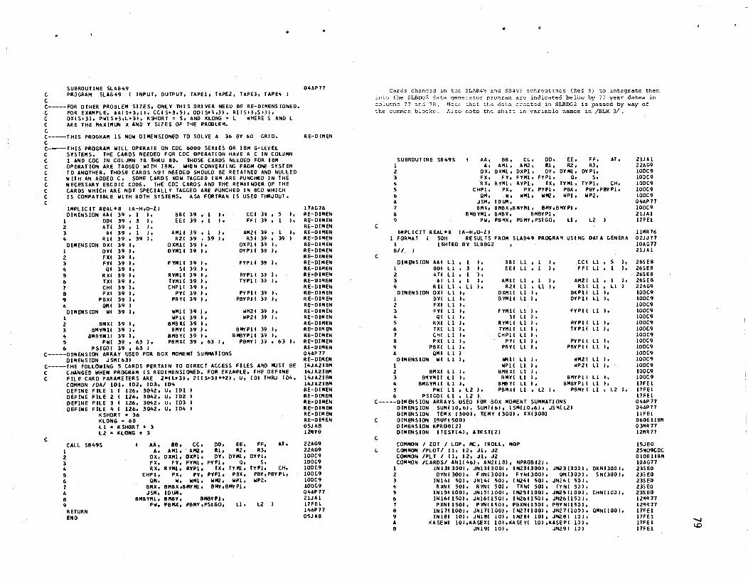
SUBROUTINE SLAB4'1 e PROGRAM SLABlt9 ( INPUT, OUTPUT, TAPEl. TAPE2, TAPE3, TAPEit I C C----FOR DTHER PROBLEM SIIES. ONLY THI S ORI veR NEED BE RE-OIMENS 10NEO. C FO!! EXAMPLE, AAIS+3'!1. eCIS+3,51, 0015+3,31, RI15+3,S+3I, C DX'S+3I, PilIS_3,L>31, KSHORT = 5, AND KLONG : L WHERE SAND L C ARE THE MUIMUN X AND V SllES OF T~E PROBLEM. C C-----THIS PROGRAM IS NDW DIMENSIONED TO SOLVE A 36 BV 60 GRID. C C-----THIS PROGRAM WILL OPERATE ON CDC 6000 SERIES OR IBII G-LEVEL C SYSTEIIS. THE CARDS NEEDED FOR CDC OPERATlDN HAVE A C IN COl~MN C I AND CDC [N COLUMN 18 THRU BO. THOSE CARDS NEEDED FOR [BM C OPERAT ION ARE TAGGED WITH 1811. IfiEN CONVERTl NG FROM ONE SYST EM C TO ANOTHER, THOSE CARDS NOT NEEDED SHOULD BE RETA[NEO AND NULLED C WITH AN ADDEO C. SOME CARDS NOW TAGGED IBM ARE PUNCHED IN THE C NECESSARY EBCDIC CODE. THE CDC CARDS AND THE REMAINDER OF THE C CARDS WHICH ARE NOT SPECIALLV TAGGED ARE PUNCHED IN BCD WHICH C IS COMPATIBLE WITH 80TH SYSTEMS. ASA FORTRAN IS USED THRl)OUT. C
IIIPLlC IT REAL.B IA-H,Q-U DIMENSION AAI 39 , 1 "
I 001 39 ,3 I, Z AT! 39 • I I, 3 AI 39 , I I, " R 11 39 , 39 "
OIIlENSION OXI 39 ), I DYI 39 I, Z FlU 39 " 3 FYI 39 ), 4 01 39 I, 5 RXI 39 I, 6 TXI 39 I, 1 CHI 39 I, o PXI 39 I, 9 PBXI 39 I, A 0111 39 J
DIMENSION III 39 " I 2 BMXI 39 h 3 BMYM 11 39 I. 4 811BYMlI 39 I. 5 P WI 39 , 63 I, 6 PSIGOI 39 • 63 I
B81 39 • I EE I 39 • 1
It I ,
AMII 39 • 1 ), R21 39 • 39 I,
DXMll 39 I, DYMII 39 ,.
FYMll SI
RYMlI TYMlI CHPlI
PYI PBYI
111411 WPII
flM8XI BMYI
8MBYI P8NXI
39 I, 39 I, 39 I, 39 I, 39 I, 39 ), 39 I.
39 I. 39 I, 39 ), 39 ), 39 I, 39 , 63 I,
CC I 39 , 5 FF I 39 • I
J, I,
AM21 R31
OXPll DVPlI
39 ,1 It 39 , 39 I 39 It 391,
fYPlI 39 I,
RYPII 39 ), TYPIt 39 I,
PYPll 39 ), PBYPll 39 I,
WM21 39 " HPZ I 39 I,
SMYPlI 39 ), BM8VPlI 39 It
PBMYI 39 , 63 It
C-----DIMENSION ARRAY USED FOR BOX MOMENT SUMMATIONS DIMENSION JSM( 631
C-----THE FOLLOWING 5 eARDS PERTAIN TO DIRECT ACCESS FILES AND MUST BE C CHANGED WHEN PROGRAM I S REDIMENSIONED. FOR EXAMPLE, THE DEFINE C FILE CARD PARAMETERS ARE Z.lb3l, 2(( S+31 •• ZI, U, IDI THRU 104.
C
COMMON 10AI 101, 102, 103, fD4 DEFINE FilE 1 I IZ6, 304Z, U, 101 DEFINE FILE Z I 126, 3042, U, IDZ DEFINE FilE 3 I 126, 30lt2, U, 103 OEFINE FILE" I 126, 3042. U, 104
KSHORT • 36 KLONG = 60 Ll z KSHORT • 3 L2 = KLONG • 3
CALL SB49S I
AA, A,
OX, F X, RX,
88, CC. AMI. . AI!2,
DXMI, DXPI, FY, FYMI,
R VMi. RVPI.
2 3 4 5 6 1 A
Pl, PY. W. ""1,
BIIBX,BIIVNI, UlUII ,
DO. EE, Rl r ttl, DY, OVIII.
FYPI, Q. TX, TYMi,
PYPl, PBX, 11K!. 111'1, BMY,BMYPI.
8 9
CHPI, OM,
BIIX, JSM,
BIIBYNI, PW,
BIlBY, OMBYPI, PBNX. POMy,PSIGO, L1,
RETURN END
FF, AT, R3,
DYPI, S,
TVPI, CH, PBY,PBVPI, NP2,
L2
O"AP77
IIE-OIMEN
11AG16 RE-OIMEN RE-OIMEN RE-DIMEN RE-DIMEN RE-DIMEN RE-DIMEN RE-DINEN RE-DIMEN RE-DIMEN RE-OIMEN RE-DfMEN RE-OIMEN RE-OIMEN RE-DIMEN RE-OIMEN RE-OIMEN RE-DIMEN RE-OIMEN RE-OIMEN RE-D[MEN RE-OIMEN RE-DIMEN RE-OIMEN O"AP71 RE-O[IIEN IitJAZI8M l"JAZIBM 14JAZIBM 14JA21BM RE-D[MEN RE-DIMEN RE-DIMEN RE-DIMEN RE-DIIIEN RE-DIMEN 05JA8 12.YO
22AG9 22AG9 100C9 100C9 100C9 100C9 100C9 100C9 04AP77 ZlJAI 11 FE I lltAP77 05JA8
•
Cards changed in into the SLBDG2 data columns 77 and 78.
SLAB49 and SB49S sunroutines {Ref 8) to integrate them
t...he common blocks Also note the
arc indicated below by 77 year dates in created in SLBOO2 is passed by way of
shift in variab1e names in /BLK 3/ •
C
C
SUBROUT INE I 2 3
" 5 6 A 1 8 9
SB49S AA, A,
OX. FX, RX,
CHPl, QII,
JSII, 8MX,
811B·VMI. PH,
INPLICIT REAL.B IA-H,Q-ZI
BB, AMI t
DXMI, FV,
R YMI. PX,
W, IDUM,
ce, AM2,
DXPI, fVMI. RYPI,
PY. WMI,
DO. RI, OY,
FVPl, lX,
PVPI, NMZ.
EE. Rl,
OV MI, Q,
TVMI, PBX, NPl,
SM8X,SNYIII, BMY,SMYPI. BMBY, CHIBVPI, PBMX, PBMV,PSIGO, ll.
FF, AT t
R3, DYPI,
S, TVPI, CH,
PBY ,PSV PI. wpz,
L2
I FORMAT '50H RESULTS fROM SLABlt9 PROGRAM USING DArl GENERA 1 15HTED BY SLBOG2 BII
DIMENSION AAI I 001 2 All 3 AI
" Rll DIMENSION DXI
I DVI 2 FXI 3 FYI 4 01 5 RXI 6 lXl 1 CHI 8 PXI '1 PBXI A OMI
DIMENSION WI I
II , I I, II ,3 I, LI ,I I, L I ,1 I, LI.lIl, II I, II I,
L I " L 1 I, L 1 I, L I I, II I. Ll I. L I ), L I It II I LI I,
2 8MXI II I. 3 B~VM II II " 4 8MBYMll LI I, 5 PWI II , L2 I, 6 PSlGO( II • L2 I
881 11 , I EE I U , 1
) . I,
AMII R21
DXMlI OVMII
fYMl! SI
RVMII TYMII CHPll
PYI PBVI
WIlli WPII
BMBXI 8MVI
BIIS YI PBMXI
11 ,I I, II , U I, U I, II I,
II I. LI I. Ll I, LI J, Ll J. II I, LI J,
Ll I. Ll I, Ll I, II I, II I, II , l2 I,
CCI Ll , 5 FFI 11 , I " l,
AM21 R31
D)(PII OYPII
Ll. lI,
Ll " II I,
fYPll Ll I,
RVPII Ll I, TVPII II ),
PVPlI U I, PBVPlI 11 "
11M2 I 11 I. IIP21 II I.
BMYPI' 11 " BNBV P 11 Ll "
I " 1I1
P8ltY Ill, L 2 "
C-----DIMENSlON ARRAVS USED FOR BOX MOME"'T SUMMATIONS
C
C
1 2 3 4 5 6 1 8 9 A 8
DIMENSION SUMIlO, 61. SUMT(6), ISMI10,61, JSMIl21 DIMENSION TEMX (300)' TEMV 13001, XX13001 DIMENSION IBUfl500J DIMENSION KPROBI21 DIMENSION ITESTlltl, ATESTl21
COMMON COMNON COMMON COMMON
I ZOT I lOP, Me, IROLL, MOP IPLOTI II. 12, JI, JZ IPLT I II, 12, Jl. J2 ICARDSI AN1(46), AN21ISI, NPROBI21,
IN 1313001, JN1313001, 11'12313001, JNZ3I300 I, OYNI3DOI, FXN(3001, FYNI3DOI, 01'113001.
INI'" SOl, JNI4! 50)' INZ'" 501, JN241 501. RXNI 50), RYNI SOl, TXNI 50)' TYNI 5JI,
IN15(100)' JNI5( 1001, INZ5110DI. JNZ5HOOI. 11'11611501, JNI61l50" IN2611501. JN261l5JIt PXN11501, PYN1l501. PBXNI1S01, P8YNIISOI.
11'11111001, JNI11!OOl, IN2111001, JNZ1110:l1, IN lSI 10), JNI81 (0), 1"'28110)' JNZ81101,
KASEWI 10l,KASEli 101,KASEV! 10I,KASEP! 10)' JNI9! 101, JNZ9! III
O)(NOOO I, SN1300"
CHNIlOJ I,
OMNIIOO"
ZIJ A I 22AG9 100C9 IOJC9 100C9 100C9 100C9 04AP11 100C9 21JAI I1FEI
11I1R16 02Nl1 10AG17 21JAI
26S E8 26SES 26SES 26SEB 22AG9 100C9 100C9 100C9 100C9 100C9 100C9 100C9 10()C9 100C9 100C9 100C9 100C9 IOOC9 100C9 100C9 l1FEI l1FEI I1FEl 04APl1 OltAPl1 11FEI 060E IIBM 03MR 11 12NR11
I5JEO 25~09tOC. o IDE 118M 10AG11 Z3SEO 23SEO 235EO 23SEO 23SEO 12'11\71 12~R 11 I1FEI I1FE 1 l1FE I 11 Fe 1
""-I 1.0

t
C t C
C
COll140N 1
COll140N 1
COM liON COli liON (;O""ON
1 (;O"~N
1
ITA8LE/NCl3, NCT). NC1~. NCT~. NC1S, NCTS, NClb. NCt6. NC17. NCT7, NC18. NCt8. NCn. NCT9
ISTiFF/POHXHY, HVDHXh OOHX3. 00HI2, OOHX. OOHXHY. HXDHY3. ODHY3. DOHYl, ODHY, tROISI
I Rl I 14)(1)3, IIYP3. NF, I TIIPP I Bll(l I HX. HY, TANSA, MXS. MY. IXO, ilL, Ml, IPGMO. PR I BLK3 I KEEP2.KEEP3.KEEP4,KEEPS,KEEP6.KEEP7,KEEPS.KEEP9.
NtDl, Ne0l, NCO~. NCOS. NC06. NCD1. NCOS, NC09 SLK~ I 18N1l01, INSIlO" SMXIlO,6).
KT8A1321. INCRWII0l, NBT. N8SM
OATA SUP I 1HSUPPORt /. STAT I 1HSTATI(;S I. STRS I 6HSTRESS I. 1 Re T / 8HREACnON/. CHK I BH CHECK /. SIIOM I 6HMOIIENT I. 2 $laX 16HSlAB x I. SLBY I 6HSLAB Y I.BLNK I 6H I. 3 IIEMX / 6HBEAII X "BEMY / 6HBEAII Y I
DATA ITESTlllt ITESTl21. ITESTUI. ITESTI"" ATESTll1t ATESTl21 1 I 1 He • 4HEA SE, IH ,~H ,ZH ~H I
DATA 101, 102, 103, ID~ IBHOEFLECTN, BHBN "OM X. 1 8HBN 11011 Y, BH SIGO /
6 fORIIAT 1 11 FOR"AT 1 SHl ,BOX. IfJ1l-----TRIM I 12 FOR"AT I SIA2,A31. A3, 2eAZ,Aft'. 213A~,A21, 3A~ I 2lA4 I 13 FORIIU 1 5X. "Al,A31. A3. 2IAz,A~" 213AhA21. 3U " !iX. 20A4 14 fOR"AT 1 A 1, A~, 5X. 17A4, A2 I 15 FOR"AT I 110t1 PROB , 15X. Al, A~. 5X, l1A~. 42 16 FORMAT IIIIITH PROB ICONTOI. 15X, AS. 5X, l1A~. A2 I 16 FORMAT I IUH PROS leONTOI. I5X, AI, A •• 5X. 17A4. Al. /I I 19 FORIIAT 11I/50H KEEP RUN TIME RECORDS FIlA FUTURE eSTIMATES OF
1 3lH PARENT AND OFF SPil.l NG RUN TIMES I 20 FORMAT S15. 5X,15,25X, IS,!, 8I5.5X.3IS,12.13.3F5.0 21 FORIIAT 215. lOX. ~e10.3 I 33 fOR"AT 41 lX. 13 " 6ElO.3 I 43 FOR"U 41 ZX. 13 I. 20X. ~ElO. 3 I 53 FORMAT 41 2X. U I, ElO.3 I 63 FOR""'T ~(2X. 13 I. 20X. 41:10.3 I 13 FORl'lAT 41 2X. 13 I. ~OX. EI0.3 I B3 FORMAT ~I 2X. 13 I. 41 4X. 11 I I 93 FORMAT 2110 I
100C9 l1FH 100C9 Z"MYl 230EO l~MRl1 0~AP11 OUPl1 O~APl1 OUP11
08FEl OBFEl OaFE! 11"11.11 26AP1610 Z6AP 1610 lSJEOCOC 15J EOCDt
04MY3 17FEl lOAG77ID 10AG1710 031111.1710 03MR111D 010EOCDC 03"11.1710 21JAl 21JAl
CLOD FORMAT II::lOH TABLE 1. CONTROL DAtA TABLE 1. CONTROL DATA TABLE NUM8ER
06DEl 2lJAl 194G8 21JA1 21JAl ZlJAl 21JAl 03FEl 060CO 2lJAICOC 060E 11 811
C
C
C
C
C
C
100 FORMAT 1 1I30H 1 I 55X. 20H 2 I ~DX. ~5H 3 1/ SX, 40H 3 II 5X._ 4 I 5X. ~OH 5 1/ 5X. 2511 6 I 5X. 25H 1 I 5X. 2,H 8 I 5X, 25H 9 I 5X, 2SH 9 I 5X, 25H
23.56 T B KEEP FRON PRECEOING PROBLEM 11~tESI KEEP FROII PRECEDI NG PROBLEM I1:YES I NUM CARDS INPUT THIS PROBlE" "UlTiPLE LOAD OPTION 15X. STATICS CHECK OPTION 15X, PRIN STRESS OPTION 15X. PROFILE PLOT OPTION 15X. rO PLOT OPTION 15X. rO PLOT OPTION 15X, TABLE 2. CONS TUTS ,
15. 15, 15, IS, 15 15
9 , , 815, • 815. , 8IS.
2lJAl 2lJAl 21JAlCOC 060E 118M 2UA1 21JAl 21JAl 2lJAl 2UA1 2LJAICDC 060E1I8" 16AG8 200 FORMAT I 112~H
2Ql FORII.T I I 45H NUI'I8ER OF tNCREIENTS IN X DIRECTION , 21JA 1 21JAl 2lJAl 2lJAlIM ZlJAICOC 2LJAlIBM ZlJAlCOC ZlJAUBM 2lJAlCOC 21JAlIM 21JAlCDC 10DEl 100£1
1 35X, IS, 2 I lOX, 35HNUMBER OF I NCREIE NTS IN Y 01 RECTI ON , .3 I lOX, 35HINCREMENT LENGTH IN X DIRECTION • 30X. .3 I lOX, 35HINCREMENT LENGTH IN X DIRECTION • 30X, ~ I lOX. 35HINCREMENT LENGTH IN Y DIRECTION ,30X. " I lOX. 35HINCREMENT LENGTH IN Y DIRECTION • 30X, S I lOX. 35HPOISSONS R4T10 • 30X. 5 I lOX. 35HPOISSONS RATIO , 30X. 6 I lOX. 35H$lAB THICKNE SS , 30X. 6 I lOX, 35H$lAS THICKNE S5 , 30X.
300 FORMU 1149H TABLE 3. JOINT BENDING STlfFNESSES. + 15HANO SUPPORTS 1 /I SOH FROM THRU ox ot 2 35H FY g S 3 I 20H JOINT JOI NT , I I
311 FORIIAT 5X. 21 lX, 12, lX, 13 I, IPI>Ell.3
35X, 15, 1 PEtO .3 •
ElO .3, IPEI0 .3.
EIO.). IPE 10.3.
ElO .3, IPElO.3 I
HO.3 , LOADS,
FX • 30AGB
C 311 FORMAT 5X. 21 lX, 12. lX. 13 I. 6£11.3'
30AG8 ::lOAG8 ZUAU811 21JAlCOC
AND APPLIED MOMENTS 100El RX • 30AG8
30AGB
400 FORMAT 1151H TABLE ~. 1" 'OH FROM 2 35H RV
"
JOINT RESTRAINTS THRU
TX TV
•
3 I 20H JOINT JOINT. I I 411 FORMAT 5X, 2( lX. 12. IX, 13 I. 22X, IP4Ell.3
t HI FORMAT 5X. 21 IX. 12, IX. 13 I, 22X, .ell.) I 500 FClRMAT I/SOH TABLE 5. IlESH TWISTING STIFFNESSES
1 1/ lOH FROM THRU C 2 I 20H ME SH ME SH ,/ I
511 FORMAT 5X. 2( lX. 12, lX, \3 I. 1Pell.3 I C 511 FORMAT 5X. 2( IX, 12. lX. 13 I, £11.3< I
30AG8 ZUAlIB" 21JAlCOC lODE! 30AGB 30AG8 21J A 11l1l'i 2UAlCOC lODE! 600 FORMAT 1140H TABLE 6. BAR AXIAL THRUSTS
1 I I !lOH FROM THRU Z 35H PY P8X pey 3 / ZOH SAil. BAR ,I I
611 FORNAT 5X. 21 lX, 12. IX. U I, 22X, IP~Ell.3 C 611 FOR"AT 5X, 2( lX. 12, lX. 13 I, 2ZX, 4Ell.3
100 FORMAT 1I35H TABLE 1. MULTIPLE LOAOS
PX , ::lOAG8 30AGB 30AG8 21JA 118M 2lJA1COC 10DEl
1" 50H FROM THRU , 30AGa 2 20H gil, 3 I 20H JOINT JOINT. I I
111 FOR"AT 5X, ZI lX. 12, IX. U I, 44X. IPEll.3 C 111 FORHAT 5X, 21 LX, 12. lX. 13 I. 44X, Ell.l I C 1100 FORMAT 1135H TABLE 8. PROFILE OUTPUT AREAS
C C
BOO FORMAT 1135H TAIILE B. PllOFILE OUTPUT AREAS • 1 /I 40H FROH THRU OEFL X MOMENT 2 3SH 'I' MOMENT PRIN MOM OR STRESS , 3 I ~2H JOINT JOINT I1"YESI I1-SLAB. 4 35H2~8EA"' Il.YESI I 3 I ~2H JOINT JOI NT llaYESI I1=SLAB, ~ 35H2-8E","I U"YESI I
811 FORMAT 5X, ZIlX.12,lX.IlI, 4X, 12, 'lX, 12. lOX. 12, l~X. 12 I I
BETA 812 FORMAT I 45H 8EAM MOMENTS ARE TOTAL PeR IlEAM 813 FORMAT I Z5X, A6. 5X, A6, !lX, 20H LARGI'ST
1 I 25X, A6. 5X, A6. 5X, A6. 2X, 20H PRINCIPAL 2 I 25X. A6. 5X, A6, 33H nil STlI«l $lAa
X TO LARGESt
30AGS 30AGa 21J A lIBH 21JAlCDt 21JAlCOC 06DElI111'1 2Ull 21JAl 2ftl'ElCDt Z4FElCDC 060ElIIII'I 06DElI111'1 16APl 22JAl 2ZJAl lOOEl
, lODE! 22JAl
, A6, 5X, A&, 5X, A6, 4X, 22JAl 1 A1. 2 25H X ,'f 0EFt. 3 A6. 4X. A6, 2X, A8 I
81ft FORMAT 25X A6. 5X A6, 33X A 1. + I 25H X,Y OEFL ,A6,5XA6.33XA81
C 815 FORMAT I 50H SLAB X MOIENT AND X TWI STING MOMENT ACT C 1 35HIN THE X DIRECTION IABOUT t AXISI • C Z I lOX. 50HY Till STING MOMENT a -X TIlISTII«l MOMENT. CWNTERCLO
815 FORIIAT I I SOH SLA8 X MOIENT AND X TWISTING MOMENT ACT
C
1 35HIN THE X DIRECTION IABOUT 'I' AXISI • 2 lOX. SOHY TWISTING MOMENT. -X tlllSTlNG NOMENT. COUNtERCLO 3 2SHCKWISE 8ETA ANGLES ARE 4 lOX, 5DHPOSITIVE FROM THE X AXIS TO THE DIRECTION OF THE L 5 t1HARGEST PRINCIPAL. A6 • 6 I lOX. 35HSLAB MOMENTS ARE PER UNI T IIIOTH 6 I lOX. 35HSLA& IIOMENTS ARE PER UNIT WiDTH
851 FORMAT 'X. IZ, lX. 13, IP3El1.3, 28X, IPE11.3 C 851 FORMAT 5X. 12. lX, 13. 3E11.3.2aX. Ell.3 I
852 FORI!U 5X, 12. lX. 13. lPSEll.3. OPF6.1, IPEl1.l C 852 FORIIU 5X, 12. lX. 13, SEll.3, F6.1. Ell.3
UJAl lOOEl 200£1 12FElCDt 22JAICDt 22JA1CDC 06DElI811 060ElIIIM 06DElI8M 22JAl 22JAl 22JAl 2ZJAICDt 06DElIM 21JA1I811 2UAlCDC 2lJAlIIII'I 2UAICDC 21JAlI811 853 FORMAT 2ZX, lP2Hl.3 I
C 853 FOR"AT I 22X, ZE 11. 3 I C 860 FORMAT 1II150H STA TIC SCHECK. C 1 6HS· • E 10.3 I
llJA1COC SUMMATION OF REACtION, 13SE8COC
21JAICOC 860 FORIIAT 1II150H STA TIC SCHECK. SU"MATION OF REACTION. 060Ell811
1 6HS t ,lP£10.3 I C B61 FORMAT / 29X 35HMAXIMUI'I StATICS CHECK ERROR AT STA ,213. C 1 2H.. Ell.3 I
861 FORMAT Z9X 35HMAXIMUI'I StATICS CHECK ERROR At StA ,213. 1 ZH t, 1PEll.3 I
86~ FORIIAT III 25H PROFILE OUTPUT AREAS I t B65 FOR"AT I SOH X MOMENTS ACt IN X DIRECTION IABOut Y AX C 1 3HISI,I,lOX. 35HTHE PLOTTED RESULTS INDICATE tHE RE C 2 ~OHLA TI VE VALUE EACH HAS III THI N THAT LIST I
865 fORMAT SOH X MOMENTS ACT I N X DIRECT ION IA80JT t AX 1 3HISld,tOX, 35HTHE PLOrrED RESULTS INOICAtE THE RE 2 ~HlA TI VE VALUE EACH HAS IoU THI N THAT LIST I
C 866 FORMAT III ~2H BETIIEEN C 1 2.H I. 13. 2H .. 13, 8H AND C. 13. 2H .. 13. 2H
B66 FORMAT III 42H BETWEeN 1 2.H I. Il. 2H 13.8H AND I, 13, ZH .. 13, 2H
060£ 118M 09FElCDt 16APICOC 060ElIBII 060ElIBM 15FEl 15FElCDC 15'1R1COC 15FElCOC 060E 11l1li 060ElIBM 060E 11811 15F! lCOC 060ElCOC Z9F E21 811 Z9FEZIBM
co o

861 FOR"Al I II
C 861 FOR"Al till
868 FOR"Al 1 II
C 868 FOR"AT C 1 II
869 FORMAT 1 /I
C 869 FOR"Al C 1 /I
870 FOR"Al 1 1/
C 870 661tMAT C 1 /I
900 FOR"Al 1 /I 2 1
903 FOR"IIT 905 FOR"Al 910 FORMAT 911 FOR "AT 920 FOR"Al 921 FORMAT
C 1
C
1 980 FOR"AT 981 FOR"AT
1 982 FOR"Al 983 FOR"AT 984 FOR"AT 985 FORMAT 986 FORHAl
1 990 FOR"AT
1 2
991 FORHAT I
992 FOR"AT 1
•
,I1X, 1l1l0EflEC TI ONS IHl 25H
1tt+ • 2SH
100el1B" 100E1l8" 100EICOC lOOEICOC 100EIIB" 100ElIBM 100Eleoe 100ElCOC 100ElIBH 100Ell8" 100EleOC 100EICOC 100Ell811 lODE lIBM 100ElCOC laOElCOC 24FEI 21JAl 21JAl 17FEl l1FEI nOE" 03FEl
IHL , 12H
X , V DEFLECTION , 17X, 11110EFlEC nONS
X , Y DEFLECTION , 9X, A6, 5H AND ,A6. lX. A6.
X , V • A6, 5H "0" , 27X A6. 5H "OM, 9X. A6, 5H AND ,AI>, IX, A6.
X , Y • A6, 5H "0" , 21X Ab. 5H MOM, , ZOX, A6, IX. A6,
1K+ • 12H
IHl 12H
IH+ 12H
X • Y • A6.5H MO" • , 20X. A6, IX, 0116,
X • Y , A6.5H MO" • 1 HI.
1711 111+
1711 1/4011
,11X. IOHPRINtIPAL. A6,
2011 2011
1 2511 46H
I 4311 1215X0I511 1 IIlS11 I 1135H
2211FROI! 22HFROM
1II140H I 1151H
35H FOR I 1150H I II SOH I 150H I 3511
X • V PRIN , A6. l1X. IOHPRINtIPAL. A6,
X , Y PRIN • A6. TABLE 9. PRINTED OUTPUT 1I "lTS
FRO" TtlRU , Y STA Y STA I
NONE , USING DATA FROM THE PREVIOUS PROBLEM AOOI TloNAL DATA FOR THIS PROBLEM
RE SUl TS 12FEl RESULTS--USIIG STlffrESS DATA, 12FEl PREVIOUS PROBLEM , AS I 2lJAl PREVIOUS PROBLEM, AI, A" I l"AP7J •••• ~OESIGNATED ERROR STOP .... } 19JE8 ..... CAunON. MULTIPLE LOADING OPTION "ISUSEO 02FEl Ttli S OR PRIOR PROBLEM .... I 02fE 1 ..... MISUSE OF MULTIPLE LOADING OPTION .... 102fEl
•••• IMPROPER NO OF CARDS INPUT OR KEPT .... I OlFEl .... X INCREMENTS EXCEED Y INCREMENTS .... I OlFEl •••• ERRONEOUS OAT A INPUT •••• I OZFE 1 •••• THE DIMENSIONED STORAGE IS TOO SHALL FOR 02FEl I 15011
30H 35H 1011 l5H
THI S SIZE OF PROBLEM •••• I 02FEl
110H 3311
1II130H 20H
•••• TOTAL NUMBER OF SPECIFIED 12FEl POINTS IS ,15, 03FEl
• 300 IS HAX .... 12FEl •••• , 14, 24FEI
OA TA ERROR SIN THI STABLE .... 19AGB ..... PROBLEH TERMINATEO ,14 23AG8
OA TA ERROR S ..... I 23AG8
e----DEFINE REAO AND WRITE UNITS INP .. 5
O'l>AP77 0401\Pll 04AP77 301101 301\101 301\101 301101 060ElIBM
lOP .. 6 101 " 0 102 .. 0 103 '" 0 10'1> .. 0 140 .. 0
C-----PROGRAN AND PROBlE" IDENTIFICATION C C--INITlAlIZE DATA NOR"AlLY READ IN TABLE
IF ( "L .EO. -I I GO TO 1005 KNL " 0
IPLflG" 0 1005 TIIK • 0.0
ITMPP .. 0 KROPT '" 0 IOPPS " 0 IPOP " 0 IGSW " 0 130 .. 0 VEF .. 0 RDF .. 0 SLOPE" 0
C-----THESE VALUES AilE ADDED TO ALLOW ECHO PRINT OF THE DATA GENERATEO C BY SLA849" TO BE PRINTED JUST AS IF iT HAD BEEN COOED.
K"l " "L SWS .. 1.0 SWI! .. 0.0 180S .. 1
1614R71 110141117 OSFE1 2lJA RLM 28APl1 031411.11 03llR17 03MR77 031411.77 03llR17 03MR77 0314R77 03111\77 OlMR77 28AP77 28AP77 14AP17 031111.77 03MR17 031111.77
IBOST ~ I NOEl 0 ND~2 .. 0 NOE 3 • {) HOE4 .. 0 NOES 0 NOE6 .. 0 HDEl .. 0 NOES .. 0 HOE9 0
..
IF KEEP 3 .EO. 0 NC T3 .. Ne03 IF KEEP" .EO. 0 NCT4 NCD4 IF KEEPS .EO. 0 NCTS .. NC05 IF KEEP6 .EO. 0 NC T6 f'«:D6 IF KEEPl .EQ. 0 Ncn NCol 1< KEEPS .EQ. 0 NCTS = NC08 IF I KEEP'1 .EO. 0 I Ne T9 .. NCD'1
C-----OM IT PR IN T OF GENERA TEO OA TA I F I IPGND .EO. 0 I GO TO '0810
C READ 12. IANliN'. N = I, 401 CI010 READ 14. NPROS. IAN21NI, N • 1. 181
1020 IF I NPROll121 - ITESTill I 1021. 9990. 1021 lOll PR INT 11
PR INT 1 PRINT 13. ANI
PRINT 15. NPRoB, AN2 C C-----INPUT TABl E I CON TROl OA TA C C C C
READ 1
20, KEEP2. KEEP3. O:EEP4, KEEP5. KEEP6. KEEP1, KEEP8.
2 KEEP9. ML. ITMPP, NeD2. NCo3, NCO", NC05. NCo6. NCD1, NC08, NCo9, KROPT, 10PPS,IPOP,IGSW. 130.VEF.RDF.SLOPE
1170 1171
140 .. 1'\>0 + 130 PRINT
I 100, KEEP2, KEEP3, KEEP'o, KEEPS. KEEP6.
KEEP9. Ne[)Z. NCil3, NC04. NC05, 2 Ncoe, NCD9, NL, KRoPT, 10PPS.
NOEl 0 IF IKML' 1174, 1110, 1172 IF I ML , 1111, 1175. 1175
NOEl" NOEl + 1 PRINT 982
GO TO 1116 1112 IF ( Ml I 1116. 11 73, 11 73 1113 PRINT 981
GO TO 1175 1114 IF I NL , 1116, IllS, 1175 1115 IF I KEEPl , 1179. 1111. 1118 1116 IF I KEEPl I 1179. 11 19, 1118 1171 IF (NCD2 I 1119, 1119, 1181l 1118 IF I NC02 I 1119. UBO, 1179 1179 NOEl .. IIDE 1 + 1
PRINT 9113 1180 KML = ML
1182 C
IF INoElI 9980, 1200, 1182 PRINT 991. IIOEI
C-----INPUT TABLE 2 - eOMSTANTS e
1200
ll01
1203
PR INT 200 IF ( KEEP2 I 9980. 1201, 1240
NOE2 • 0 IF I NeD2 - 1 I 1203, 1205. Il03
NDE2 • NOEl + I PRINT 985
C1205 READ 21. MX. MY, HX, IIY. PRo TtlK 1205 PRINT 201, "X. MV. HX. HV, PRo IliK
IF I MX - MY I 1211. 1211. 1210 NOEl = NDE2 + 1 1210
KEEP1, KEEPS, NCOb, IIC07. I PDP. 130
The statements which originally read the data cards in Tables 2 have been nulled with a C in column 1. The remainder of the data print logic is the same as in the original SB49.S routine (Ref 8) •
03~R 77 03~R17 03~R 71 0314R17 03MR71 0314R11 03HR 71 03'1R 11 03~R71 03MR11 28AP17 l8AP17 28AP77 28APl1 28AP77 28AP71 28AP11 14AP71 28AP71 031411.71 03MR11 11'1Rll 11'111.77 llMR11 03MRl1 0:JMR77
02FEl
031111.11 03~Rl1
03MR77 DioDE! 18HYO ObJCO OlFEl 02FEI 02FEl 02FE1 OlFEl 05FEl 02FEI 02FE1 OlFEl 02FEI OlFEl 02FEI 02FEI 02FEl 02FEl 02FEl 05F5l 02FEl Z3FEl 05FEl
OlFEl
02FE1 24FEl 26AGB 28AG8 Z6AG8 Z3FEI 03'1R11 03'1R71 19AG8 lbAGS
9
CO .....

The preceding 438 cards are exactly the same as in SB49S (Ref 8) and are thus omitted from this listing.
C-----f'R INT HEADINGS b
fOR CO"81NEO SLA8 ANO BEAM OUTPUT 6HO PIIINT
I'll INT PUNT PRINT PRINT
815. SOM 812 6 813, SLBX. SlBY. 811014. BIIOII. Stax.
+ 61.5 6115 6116
BEMX, BEHV. ROSCI. 8MOII. 8"014. SIIOM. SOH. SOM, ROSC2 IF (IOPPSI 9980. b180. 6115 If ( THI( I 9900, 6180. 6176
5012 ~ 6.0 I ( THK $ THK I GO TO 6200
6180 C
SOT2 ~ 1.0
C-----COMPUTE BEND ING MOMENTS. REAC TI ONS ANO Till STI NG MOMENTS C C-----OETERIIINE IF BOX "OMENT SUMS WILL BE !'lADE. INITIAte STORAGE
IF I NBSH .EQ. 0 I GO TO 6199
6181
00 6181 J ~ 1. HYP3 JSHIJI = 0
CONT INUE 00 61 B3 J J = 1. NB SH DO 6182 II = 1. 6
SUHIJJ.III c 0.0 6182 CONTINUE 6183 CONTINUE
C-----OETERMINE Y-STA LIMITS TO HAVE 80X SUNS. IF A SUM IS TO BE C MADE. SET JSjII = TO BOX NUMBER.
618.
00 618B JJ ~ I, NilS!! JY2 = 0 NB • 181\11JJI
00 6184 K ~ I, ~B JY2 • JY2 .. INCRWI KTBAI III I
CONTl!lUE JVl = JYZ - U~RWI KTBAINBI I
00 6181 J * 1. "YP3 IF I J .L T. I JY1 .. 2 I IGO TO 6181 If I J .GT. ( JV2 + 2 I I GO TO 6188
JSMIJI c !l8 c-----oeUIII'IINE CLOSEST x-Sfll ro LOCATION 1&'IIERE SUM IS NEEDED
K & INSIJJI
US6 6187 6188 6199 6200
6250
6300
6400
00 6186 I. 1. K ISMIJJ.II z ( SMXIJJ.II .. HX/2.0 I I HlC - IXO
CONTINUE CONTINUE CO!lTlNUE CONTINUE 00 8650 II • 1. MVP3
J ~ MvP. - Ll 00 6250 I ~ 1. MlIP::!
WPZIII .111'1111 MPH II & 11111 Will ~ 11141111 IIIHII) • 111421 1/
CONTINUE 00 6300 I & I, PllIP3
11142111 .PIIII,JI CONT INUE IF I HYP 1 - J I 8650. 6.00. 6500 00 6450 I· Z, MlIP2
CROIZI • OMINI I OXIII. OYIII I WSUHIH • OOHX2 .. I 111'1111-11 - 2.0 .. 11141111
II SUMII 2 IIMYM 1111 BHBY" 111'
• 1114111+1/ I • 00HY2 • I IIIIZIII - 2.0 .. IIM1( II .. W III I
DYIII • IISUIIM2 + C1I0(21 * PR • iofSUlllll F VIII .. IISUIIIIZ
08FEl 16AP 1 08FEl OBFE! 100El lODE I 060CO 09FEl 06;)CO 09FEI 060CO
O.AP11 04AP17 04AP71 04AP71 O.APll 04AP11 0.AP17 041<1'11 04APll 04AP1T 04AP11 O.AP71 O.APl1 O~AP11 04AP71 041<1'71 04AP11 O.APl1 04AP11 04AP71 04APll 04APl1 0.AP71 04AP71 08AP17 0.AP71 04AI'17 04AP17 04AI'71 OUP11 O.AP71 15HRI 24JL8 08JL8 08JL8 OSJL8 05JL8 05JL8 08JL8 12MYO I2HYO IZMYO 02'1Al 24JL8 l1"R 16 05Jl8 05Jl8 05JL8 05AG9 26JL8
..
6.50
6500
CONTINUE GO TO 8650 DO 1200 I = 2. MXP2
CROl21 & OHINI I DXIII. OVIII I CROl41 • OMINI ( OxM111'. OY"1111
24JL8 09FEl 08JL8 llMR76 11MR76
The following 107 cards are exactly the sattle as in SB49S (Ref 6) aud are thus omitted from this listing.
C-----COHPUTE PRINCIPAL MOHENTS OR STRESSES C
8060
C
SMA ~ 0.5 .. ( BIIXIII + 8MYIII TIIY = - TMX BMP = SM XI II SMA 8MR =OSQR T I BMP .. 8MP • TH" .. THY SHR ~ SQR T I SI4P .. 8 MP + TIIV .. THY SilO = SMA + 8MR 8HT ¥ 811A - 8MR
C-----TEST TO PRINT ONLY THE MAXIIIUM VALUE IF I 8"A I 8160. 8180, 8180
8160 PMMAX "BMT IF BMP , 8400. 8300, 8200
8180 PIIIIAX 8140 IF BliP I 8200. 8300, 8.00
8200 AL F = TI1Y I 8 HI' ALF =OA TAN I ALF I • 51,29578
C ALF " ATAN I ALF I .. S1.29518
C
8220
8240
8300 8320
83.0
8360
8400
If ALF I 8220. 8240. 8240 THETA - ALF - IBO.O
GO TO 8450 THETA
GO TO 8450 + 180.0 - ALI'
IF I THY I B320. 8340. 8360 THETA + 90.0
GO TO 8450 THETA = 0.0
GO TO B450 THETA
GO TO 8450 - 90.0
ALF = TIIV I 8MI' ALF =OA TAN C AlF ALF " AlAN t AlF THETA • - ALF
C-----CLOCI(WISE AIiGLES ARE NEGATIVE 8.50 8ETA = 0.5 .. THETA
SIGO = PIIHAX .. SOTZ PSIGDII.J+21 • smo
C-----PRINT SLAB ONLY OUTPUT
.. 51.29518 • 51.29518
IF I IPRINT I 9980. 8458. ~54 8.5. PRINT 852. ISTA, JSJA. 11111. 8MXCII. 811vllJ, THX. SIGO,
I 8 ETA • ROCK C----PRINT 8EAM OUTPUT IF COMSI NED
8458 IF I SW8 1 9980. 8410, ~60 8460 IF ( IPRINT I 9980. ~10. 8465 8465 PRINT 853. BII8XII,. 81'18 YIII 8410 JP 2 " J + 2
IF I JSMIJP21 .EO. 0 I GO TO U50 C-----FINO BOX WITH SUM. JJ WILL 8E SOx lNOEX
00 ~15 JJ = 1. NBSII
8415 If ( JSHIJP21 .EQ. 18NIJJI I GO TO 8480 CONTINUE
WR IfE 1 lOP. 8211 821 FORMAT I I 45H
GO TO 8550 ....... INVALID MOMENT SUII SPECIFIED
C---FINO X-STA TO 8E SUHMEO. II WILL BE X-STA I NOEX
•
.. _.
14NOl
08JL8 010EO 08JL8 070EO IBI'I 01DEOCDC 08JL8 08JL8 150H 08JL8 08JL8 OSJL8 08JL8 08JL8 010EO 070EOl814 010EOCOC 010EO 010EO OBJLB 010EO 08JLS 070EO 010EO 08JL8 08JL8 08JL8 010EO 08JL8 010EO 010EOIB14 010EOCDC 010EO 150El 09Fet 08JL8 15JLO
1514Rl 1511R 1 09FEl
04AP71 04AP11 1514Rl llAP11 l1APl1 044P11 OftAP11 llAP11 04AP71 08AP11 08AP 11 08APH 04AP71
co N

8480
8485
8490
8495
8500
8502
8505
8510
8515
1520
8525
8510
8532 8550
8600 tALL
I 2 3 It 5 6
8610
It a INSIJJI 00 81t85 II. I, K IF I (SIIIJJ.I1I .EO. ISTA 1 GO TO 81t,0 CONTINUE IF (JSMIJP21 .EO. JSP'l1 JP2-1I 1 GO TO 8550 GO TO 8495 IF l JSP'IIJP2+11 .EO. 0 I GO TO 8500 IF 1 JSP'IIJP21 .EO. JS'UJP2-11 I GO TO 8505 IF 1 JSMIJP2-11 .EO. 0' GO TO 8525 GO TO 8510 IF 1 JP2 .EO. 2 .011,. JP2 .EO. I4YP2 GO TO 8502
SUMIJJ,III • 811XIII • ~Y • 0.5 GO TO 8550
SUI'IIJJ,llI ., 8MXII' • HY GO TO 8550
SUMIJJ,IlI = SUM!JJ,1I1 + 8MXIII • HY IF I JSMIJP21 .EO. JSMI JP2+1I 1 GO TO 8550
SUM!JJ,III = SUIIIJJ,III + SUMT!II' GO TO 8550
K = IIIISIJJ-lI 00 8515 II T = I, K IF I ISMIJJ-I,IlTl .EO. I STA I GO TO 8520 CaNT lNUE GO TO 8525 IF I JSIIIJP21 .EO. JSIIIJP2-11 I GO TO 8525
SUMTlllT1 814XIII. HY. 0.5 IF I lSMIJJ,lll .EI:!. ISTA I GO TO 8530 GO TO 8550 IF I JP2 .EO. 2 .OR. JP2 .EO. IIYP2 1 GO TO 8532
SUI'IlJJ.Ill = SUMIJJ,I11 + BMXIlI • HY .0.5 GO TO 8550
SUMIJJ,lIl = SUMIJJ,lll + 8MXII) • HY CONT INUE IF I I SW I 9980, 8600, 8650
IN • J - I DATA LI, IN, I, MXP1,
OX, DYMI, OY,OYPI, FX, FYP'lI. FY, FYPI, O. s, Rx, RYP'lI, RYPI. TX. TVI'll. TVPI. CH, CHPI, DXPh OXIII. PX, PY, PYPI. PBX, P8Y, P8YP1, 014, IPRINT
IF l J - I I 9980. 8610, 8650 ISII " 1
00 8620 I· I. MXP3 IIP2(11 ., IIPIIII lIP 11 II • 11111 11111 • 11141(11 IIMlIl1 • IIIIllIl IIl1llll • 0.0
8620 tONTllIIUE 00 8610 1 = 2, MXP2
tROl21 • OMINI I OXIII. OYlIl I 811YP 1111 "BIIYIlI 8MYIII ., BIIYMIIII BMYMUII & 0.0 BIIB YP Uti • 11MB YllI BMBYIII = BMBYlIlIlI BMBYMlIli = 0.0 WSUIII = DOHX2 • I 1111-11 - 2.0 • Will. 1111+11 IISUI'I2 2 00liY2 • ! 11111111 - 2.0 • 11111 + IIPlll1 BMXIII • OXIII " IISUIII + tRDll1 • PR • IISUM2 8MB)(111 ., FXIII • IISUMI
t---BMX AND 8MY ARE AT STATION O. PBIIX ANO PBMYARE STORED AT J • 2 IF I IBO S .Eg. 2 I GO TO 8625
PBM)(I t. 2 I ·8MXIII PBMYII. 2 I • BMYIII
GO TO 8UO 8625 PBMXII, 2 • BMBXIII
P8MYII, 2 BMBYIII 8630 CONTINUE
JSTA • 0 J = 0
GO TO 7300
04AP71 OItAP77 04AP17 OItAP71 llAP17 04AP71 llAP 17 llAP77 11AP77 OItAP77 llAP71 IUP77 OItAP77 llAP17 llAP71 OItAP71 llAP 71 OItAP77 OItAPl1 OItAP71 OItAP71 OItAP11 OItAP71 0ltAP77 llAP77 OItAP71 OItAP77 OItAP77 llAP71 llAP71 llAP77 llAP 11 08JL8 09FEl 24JL8 D9FEl 21tJE8 2ltJE8 244E8 05AG9 24JE8 IS!lRl 070EO 07DEO 09FEl 2<1>JL8 05JL8 05JL8 05JLB 24JL8 07DEO 070EO 11111176 OBJL8 08JLB 24JL8 08JL8 OUL8 2ltJL 8 08JL8 08JL8 05AG9 08JL8
llFel ZUPI 21API llFEI 21AP 1 21API 07DEO 26JL8 l5JLO Z<I>JL8
I>
8650 CON T1111 ue PR INT 860, SUMR PRIIIIT 8610 ITEMP. HEMP. STEMI'
C-----I'I< INT BOX MOMENT SUMS IF I N8SM .EO. 0 I GO TO 8658
WRITE 1I0P.8201 820 FORMAT 1III1t5H BOX MOMEIIIT SUMMATIOIIIS ITOTAL AClOSS BO~I
1 /I 51H BOX NO. x-sa X-DI S r TOT At DO 8656 JJ. 1. N8SM
It = IIIISIJJI DO 8651t II. 1. It
XO a I 1SP'IIJJ.t1l + IXO I • HX IIRITE IIOP,8251 IBNIJJI. ISI1IJJ,III. XD. SUI'IIJJ.1l1
825 FORP'lAT I lOX, 21 14, 5X I, lPEI0.3. lPE13.3 I 8651t CONTINUE
wRITE 110f',61 8656 CaNT INue
GO TO 8659 8658 wRITE IIOP,8281 828 FORHAT 1II13OM NO 80X SUMS SPECIFIED
8659 CONTlIIIUe C ••••••• 1110 lOT, SpLOT ONLY. FOR IBM •••••••••••
IpDP = 0 t IFIIPOP .GT. 0 .OR. 130 .EI:!. II CALL PLOTS! IBUF,5l0,1Dl C----- 3D PLOT CAPA81LITY OMITTED fOR THIS VERSION •••••••••••••
07DEO USE8 09FEl OItAP77 OItAP71 OItAP77 OItAP71
8MXI02JU71 OItAP71 OItAp71 OItAP77 OlJU77 02JJ77 02JU77 OItAP71 llAP77 04AP71 OItAP71 o ItAP 77 o ItAP 77 OItAP71 30NOI 3DNOllBM ]ONO lIBI'I llllR76
The following 154 cards are exactly the same as in SB49S (aef S) and are thus omitted from this listing.
t-----L1NE PLOTS NOT AYAILABLE THI S VERSIOIII NP2 • NENO + 2
8872
88BIt 8885 8950
DO 8872 lei. NP2 XXI II = I - I
IF I IPOP .EO.I CONTINUE
GO TO
CONTINUE CONTINUE IF I 13D.EO.I
IPR INT 9099
8865
9099 fORMAT I 1150H •••• 3D PLOT NOT AVAILABLE THIS VERSION •••• I C CALL TIC TOt Iltl C GO TO 1010 C-----RETURN TO DATA GENERA TOR
RETURIII 9980 PRlIIIT 980 9990 CONTINUE 9999 CONTIIIIUE
C----- 3D PLOTS NOT AYAILABLE THI S III:RSION C IF I IPOP.GT.O .0R.I3D.EO.l I CALL ENDPLT
PRINT 11 PR I lilT 1 PR IIIIT 13. AlIIl CALL TIt TOt 121 PRINT 19 RETURN END
The remainder of the subroutines are exactly the same- as those used for SLAB 49 (Ref e). The only changes are total double precisioning and the increase in the axial thrust array sizes in common block ICARnSI of subroutine STIFF. 119B cards are thus omitted from this listi"".
11111176 l'JJ EO 110EO 110eO 110EO 110EO 1l0EO lZI1YO 260CO 1l1\R76 11~R76 lltAp77 0311R77 03MR77 03,.R77 19JEB I'MRS O""'Y] lIMR76 IItMY lCOC 0811Y3 21JL 7 060eO l6SE6 lOAGl 23NOI
co Vol

APPENDIX D
TYPICAL OUTPUT
PROGRAM SLBDG 2

• •
PROGRA~ SL BDG2 BRIDGE DIYl SiaN, TEXAS DOHP1 PANAK I-----TR 1M
REY IS I ON OAT E 10 AlJG 71
POST reST ANALYSIS OF BfEYILLE STRUCTURE
14 SPA,~ INCRS. 44 TRANSVE~SE It.CREMENTS RUN AS CHECK fOR 10 AUG 77 VERSIJ~
PROB 170A LOAO (NG NO. ONE EAST EDGE
fASL E 1. CONTROL DATA
KEEP FR~ PRECEDING PROBLEM tl~YESI
NUM CARDS INPUT THIS PPGBLEM
MULTIPLE LOAD OPTION PRINT GENERATEO DATA SK EW ANGLE
TABLE 2. CONSTANTS
o 1
1 o
0.3740 02
NUMBER Of SPAN INCREMENTS IN X DIRECTION NUMBER OF INCREMENTS IN Y DIRECTION
TABLE Nll~BER 4 5 6
o 2
o 1
INCREMENT LENGTH IN X DIRECTION IALON~ SPAN CENTERLlNE) INCREMENT LENGTH IN Y DIRECTION POISSONS RATIO MODULUS O.F ELASTIC I TV
fABLE 3. BOX STIFFNESS DATA
o 2
8
o 3
9
o 3
14 44
3.739001 1.2160 01 1.5000-01 6.2000 03
TYPE NO.
NO. I~CR BOX VOID SLAB T~ICK TOP BOT
5.50 5.00
SHEAR KEY LONGIT. BOX INERTIAS IN WIDTH DEP WIDTH
1 4 20.00 23.15
TABLE 4. 60X ARRANGEMENt BY TYPE NO.
TABLE 5. LOAD PATTERNS
STI FF F ACT OR 0.1000-05
PAT X AND Y DISTANCES lOF THE LOAD PATTERN) LOS LOAD MAGNITUDE
MOMENT TORS toNAL 3.0990 04 7.1980 04
1 -110. -39.-110. 39. -25. -36. -2,. 36. 25. -3D. 25. 36. 6 -5.9300 00 -5.~300 oa -1.455) 01 -1.4550 01 -1.4;5001 -1.455001
TABLE 6. PLACEMENTS OF LOAD PATTERNS
PAT-PLMTS )( AND Y OIST~NCES 10F THE STRUCTUREI 1 1 ~02. 181.
TABLE 7. SUMMATION OF BOX BENDING MOMENTS
BOX SUIIS SUM AT X-STATION NEAREST THESE X-DISTANces to 5 370. "'06. H2. 418. 51 .... 11 5 310. "'06. H2. 478. 514.
TABLE B·. PROFILE OUTPUT AREAS
OISTS FROM - THRU X Y X Y
160. 242. 727. 242. -38. O. 562. O.
-204.-2 ... 2. 360.-242.
DEft
TA8LE 9. PRINTED OUTPUT LIMITS
X 140M Y HOM Il=YESI
o 0 o 0 o 0
PRIN MOM
o o o
V-DIST FROM -Y
-21>8. 12.
243.
THR~
Y - 243.
12. 268.
SUMMAT [ON OF LOADS ON STRUC TlJRE SUMMATION OF LOADS OFf STRlJCTURE
-1.0060 01 J.O
RESULTS FROM SLAB49 PROGRAM USI ~ DATA GENERATEO BY SLBOG2
POST TEST A"IALYSIS OF 9EEVILtE STRUCTURE
14 SPAN INCRS, 44 TRANSVERSE INCREMENTS RUN AS CHECK FOR 10 AUG 77 VERS ION
PRnB (CONTD) 110A LOAOING NO. ONE EAST EDGE
RESULTS
SLAB X MOIIENT AND x TWISTlN; MJ~ENT ACT I~ THE X DIRECTION IABOUT Y AXISI Y TWISTING MOMENT -x TwISTlN.; "nMENT, COUNTERCLOCK~Is.e BETA ANGLES ARE POSITIVE FROM TH~ X AXIS TO TH~ O[RECrrON Of THE LARGE;T PRINCIPAL ",ONENT SLAB MOMENTS ARE PER U"IT WI 0 Trl
LARGEST 8ETA SLAB x PRINCIPAL X TO
SLAB X SLAB Y TWISTING HAB LARGEST SUPPORT X • Y OEFL MOMENT MOME NT MOMENT MO~ENT !'IOMENT RueTIO ..
0 44 0.0 O. C 0.0 0.0 ~.O ~ .0 0.0 1 44 0.0 0.0 0.0 0.0 ~.3 J.O 0.0 2 4'" 0.0 0.0 0.0 0.0 ).0 0.0 0.0 3 4'" 0.0 0.0 a.;) 0.0 ).0 3.0 0.0 4 "" 0.0 0.0 0.1) 0.0 3.0 3 .0 0.0 5 44 0.0 0.0 0.0 0.0 J.~ 0.0 0.0 6 4ft 0.0 0.0 0.0 0.0 3.0 a.O 0.0 7 44 0.0 0.0 0.0 0.0 3.0 0.0 0.0 8 4'" 0.0 0.0 0.0 0.0 3.0 0.0 0.0 9 4 ... 0.0 0.0 0.0 0.0 0.0 a.o 0.0
10 ...... 2.9930-02 0.0 0.0 0.0 ).3 0.0 0.0 11 4 ... 1.0200-02 -3.1260 00 7.1020-110 1.9220 01 -2.0850 01 -42.7 -3.1770 04 12 44 -1.1700-02 -1.n60 00 -2.8920-16 -1.8"'",0 00 -2.9800 00 31.8 1.3790 04 II 't4 -3.4970-02 2.2140 00 -1 •• 680-15 -2.6100 00 4.127000 -34.2 0.0 14 ... 4 -5.6500-02 4.6900 00 -2.3760-15 -2.71010 00 ; .9070 30 -2 .... 8 0.0 15 ... 4 -7.4890-02 7.0780 00 -3.2340-15 -2.7390 00 9.015000 -18.9 0.0 16 44 -8.8390-02 9 •• 640 00 -3.8720-15 -2.31040 00 1.0110 Jt -15.7 0.0
CO (J1
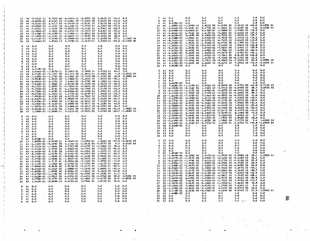
11 44 -9.5410-02 9.1330 00 -4.2200-15 -3.0950 00 1.01030 Jl -16.2 0.0 1 41 0.0 0.0 0.0 0.0 ).l J.O 0.0
18 44 -9.5690- 02 8.4930 00 -4.26100-15 -3.2640 00 9.602D 00 -18.8 0.0 8 41 0.0 0.0 0.0 G.O J.O a.o 0.0
19 44 -9.0100-02 6.4210 00 -4.0410-15 -3.3130 00 1.8230 00 -22.9 0.0 9 41 3.3350-02 0.0 0.0 0.0 3.0 3.0 0.0
20 44 -8.0000-02 4.4500 00 -3.6280-15 -3.214000 ~.1840 00 -27.9 0.0 10 "1 1.3990-02 -1.3990-10 1.0110 00 -4.8190 30 5.3510 00 -48.0 -2."250 04
21 "4 -6.6950-02 2.6520 00 -3.0010-15 -3.2000 00 4.190000 -33.7 0.0 11 41 -5.4240- 03 - 5. 10930 00 2.4790 00 -1.0220 DO -5.81JO 30 7.0 2.4230 04
22 44 -5.2000-02 1.005D 00 -2.4250-15 -3.0820 00 3.6260 00 -40.4 0.0 12 41 - 2. 6980- 02 - 2."810- 01 4.6160-01 -1.3680 DO 1.5240 lO -52.3 0.0
Z3 44 -3.6360-02 -4.1430-01 -1.1480-15 -2.8850 00 -3.0990 DO 42.9 0.0 13 41 -4.81040-02 4.7530 00 1.10170-01 -3.2060 00 6."000 00 -27.2 0.0
24 44 -2.1000-02 -1.249D 00 -1.0820-15 -2.5100 00 -3.2100 00 38.0 0.0 14 41 -6.81030-02 9.1690 00 8.3900-02 -3.7210 00 1.050001 -19.7 0.0
25 44 -6.5110-03 -7.4490-01 -4.5000-16 -1.4180 00 -1.8390 00 37 .1> 2.1560 04 15 41 -8.5380-02 1.3860 01 2.5500-02 -J.7510 00 1.4S10 01 -14.2 0.0 26 44 1.4660- 03 1.2560-14 1.1590-16 -2.3200-~1 2.3200-01 -45.0 -2.1560 04 16 41 -9.7240-02 1.9340 01 -2.~370-01 -4.7220 00 2.0420 U -12.9 0.0
11 41 -1.0230-01 1.9870 01 -1.7480-01 -10.4130 00 2.178001 -16.4 0.0
0 43 0.0 0.0 0.0 0.0 J .0 0.0 0.0 18 41 -1.0020- 01 1.1050 01 -9.1040-02 -7.618030 1.99 ... 0 Jl -2l.8 0.0
1 43 0.0 0.0 0.0 0.0 0.0 0.0 0.0 19 41 -9"2180-02 1.2490 01 2.8400-02 -7.92&0 00 1.6340 Jl -25.9 0.0
2 43 0.0 0.0 0.0 0.0 0.0 0.0 0.0 20 41 -7.9710-02 8.10050 00 6.4980-02 -7.7980 00 1.3230 H -30.6 0.0
3 43 0.0 0.0 0.0 0.0 0.0 J.O 0.0 21 41 -10.4200-02 5.0850 00 1.0630-01 -7.7570 00 1.074001 -36.1 0.0
" 43 0.0 0.0 0.0 0.0 J .0 0.0 0.0 22 41 -4.10910- 02 1.8040 00 1.6010-(11 -7.7840 00 8.8.190 00 -42.0 0.0
5 "3 0.0 0.0 0.0 0.0 J.O 0.0 0.0 23 41 -2.8980-02 -1.2320 00 4.5410-01 -7.7380 00 -9.172000 Itl.9 0.0
6 lt3 0.0 0.0 0.0 0.0 0.0 3.0 0.0 24 41 -1.1510-02 -3.78CO 00 2.1810 00 -5.9010000 -7.255030 30.5 1.9950 04
7 43 0.0 0.0 0.0 0.0 3.0 0.0 0.0 25 41 4.4180- 03 -4.1820 00 10.0420 00 -3.615D 00 7.1910 3a -72.4 -2.0000 04
8 H 0.0 0.0 0.0 0.0 J.o 0.0 0.0 26 41 1.8bSO-02 0.0 0.0 0.0 l.O 0.0 0.0
9 43 .... 4110- 02 O. C o.a 0.0 3.0 0.0 0.0 10 43 2.4460-02 -7.9170-11 3.3060-01 2.7090 01 2.725001 45.2 0.0 0 23 0.0 0.0 0.0 0.0 3.J 0.0 0.0
11 43 4.1220- 03 - 5.1400 00 3.1110 00 -6.9870-01 -5.199030 4.8 -2.2910 04 1 23 0.0 0.0 0.0 0.0 l.a 3.0 0.0
12 43 -1.6990-02 -2.178;) 00 1.2860 00 -3.2220 00 -~.1050 00 30.9 2.2890 04 2 23 0.0 0.0 0.0 0.0 l.O 0.0 0.0
13 43 -3.9530-02 4.3530 00 1.7880-01 -5.23~O 00 1.901030 -34.1 0.0 3 23 0.0 0.0 0.0 0.0 l.O 0.0 0.0
14 43 -6.0540-02 9.1570 00 7.1460-02 -5.2190 00 1.1580 H -2406 0.0 4 23 0.0 0.0 0.0 0.0 0.0 0.0 0.0
15 43 -7.8320-02 1.3860 01 2.3130-06 -5.2370 00 1.5610 01 -18.5· 0.0 5 23 3.8190-03 0.0 0.0 0.0 0.0 0.0 0.0
16 43 -9.1210-02 1.8490 01 -1.1340-01 -5.5870 00 2.0030 01 -15.5 0.0 I> 23 7.9b8[)-04 -1.1370-11 3.3010 03 -2.2950 00 ~.4770 00 -62.9 -3.7130 03
17 43 -9.1540-02 1.9190 01 -1.6700-01 -6.2390 30 2.1030 n -16.4 0.0 7 23 -2.3920-03 -2.1460 00 1.4620 00 -2.8310 00 -3.6990 00 28.7 3.6850 03
18 43 -9.1090-02 1.6100 01 -8.8930-02 -0.6990 00 1.9040 01 -19.3 0.0 8 23 -6.4140-03 -2.1510 00 2.6560-01 -3.8070 00 -4.9410 00 36.2 0.0
19 43 -9.0730-02 1.2550 01 1.5710-02 -6.8290 00 1.556001 -23.7 0.0 9 23 -1.1210-02 -1.7040 00 1.2400-01 -4.3650 00 -;.2490 JO 39.1 0.0
20 43 -7.9930-02 8.6780 00 6.3110-02 -6.734000 1.2360 JI -28.7 0.0 10 23 -1.6620-02 -7.4390-01 7.Q8bO-02 -4.9070 30 -;.257030 42.6 0.0
21 43 -10.6010-02 5.1450 00 1.01080-01 -10.5110 00 9.6630 00 -34.5 0.0 II 23 -2.2290-02 6.29S0-01 4.0110-02 -5.2590 30 5.6020 00 -43.4 0.0
22 43 -5.0390-02 1.8950 00 1.7080-01 -6.3240 JD 7.415000 -41.1 0.0 12 23 -2.7740-02 2.2460 00 5.7350-0J -5.3150 30 10.5510 00 -39.0 0.0
23 43 -3.4060-02 -9.4120-01 2.8300-01 -5.9070 00 -~.2680 00 42.0 0.0 13 23 -3.2400-02 3.9050 00 -2.51>60-02 -5.0430 30 7.3520 00 -34.4 0.0
24 43 -1.8070-02 -2.7010 00 5.4960-01 -5.2010 00 -6.5290 30 36.3 0.0 14 23 -3.5680-02 5.5010 00 -6.1110-02 -4.4420 30 1.9&50 30 -29.0 0.0
25 43 -3.0630-03 -2.2150 00 2.3160 00 -2.8040 00 3.6560 00 -64.5 1.4860 04 IS 23 -3.7010-02 10.9300 00 -1.0750-01 -3.4920 00 8.3&80 30 -22.4 0.0
2& 43 1.1040-02 -1.0890-11 9.3110-01 -3.9870-01 1.0780 00 -69.7 --1.4880 04 16 23 -3.5880-02 1.9320 00 -1.10110-01 -2.21ID 30 8.4970 lO -·14.3 0.0 11 23 -3.1940-02 8.1860 00 -2.331>0-01 -7.8190-01 8.2580 ~ -5.3 0.0
0 42 0.0 0.0 0.0 0.0 J.O 0.0 0.0 Ii 23 -2.5090-02 7.10460 00 -3.1810-01 5.2160-Ql 7.6800 03 3.7 0.0
1 42 0.0 0.0 0.0 0.0 J.O 0.0 0.0 19 2l -1.5530-02 10.5130 00 -4.5230-01 1.7950 00 6.9480 00 13.6 0.0
2 42 0.0 0.0 0.0 0.0 J.O 0.0 0.0 20 23 -3.&390-03 7.5130 00 -1.8250 00 1.590D 30 7.717000 9.4 1.6960 04
3 42 0.0 0.0 0.0 0.0 J.o 0.0 0.0 21 23 1.1000-02 10.0460-13 -8.7070-01 1.6320 01 -1.&76001 -45.8 -'1.6940 04
4 42 0.0 0.0 0.0 0.0 J.a 0.0 0.0 22 23 2.51>80-02 0.0 0.0 0.0 :) .• 0 J ~o 0.0
5 42 0.0 0.0 0.0 0.0 J.O 0.0 0.0 23 23 0.0 0.0 0.0 0.0 ).0 0.0 0.0
10 42 0.0 0.0 0.0 0.0 ~.O 0.0 0.0 24 23 0.0 0.0 0.0 0.0 0.0 0.0 0.0
7 42 0.0 0.0 0.0 0.0 0.0 0.0 0.0 25 Z3 0.0 0.0 0.0 0.0 J.O 0.0 0.0
8 42 0.0 0.0 0.0 0.0 0.0 0.0 0.0 26 23 0.0 0.0 0.0 0.0 3.0 0.0 0.0
9 42 3.85!1O- 02 0.0 0.0 0.0 J.O 0.0 0.0 10 42 1.8990-02 -1.0440-11 4.1640-01 -7.4040-01 1.01100 00 -53.9 -3.1>610 03 0 22 0.0 0.0 0.0 0.0 J.O 3.0 0.0
11 42 -6.1200-04 -5.6850 00 5.1150-01 -1.0470 00 -5.8570 00 9.3 3.6760 03 1 22 0.0 0.0 0.0 0.0 J.O 0.0 0.0
12 42 -2.2210-02 -1.0660 00 4.7740-01 -2.2770 00 -2.6980 00 35.6 0.0 2 22 0.0 0.0 0.0 0.0 0.0 0.0 0.0
13 42 -4.4210-02 4.5850 00 2.8360-01 -4.1760 00 7.1320 JO -31.4 0.0 3 22 0.0 0.0 0.0 0.0 J .a 3.0 0.0
14 42 -6.4630-02 9.3350 00 1.4340-01 -4.4960 00 1.1110 Jl -22.2 0.0 " 22 0.0 0.0 0.0 0.0 3.0 a~o 0.0
15 42 -8.1830-02 1.4150 01 2.10240-02 -4.501000 1.5460 H -16.3 0.0 5 22 1.8440-03 0.0 0.0 o.a 0.0 a.o 0.0
16 42 -9.4130- 02 1.9160 01 -8.8590-02 -5.160000 2.0450 01 -14.1 0.0 6 22 -1.9490-06 -3.2090 00 3.5470-01 -1.8550 00 -3.9990 00 23.1 1.2080 01
11 42 -9.979D-Ol 1.9830 01 -1.0810-01 -6.3520 00 2.1680 31 -16.3 0.0 7 22 -2.9710-03 -1.8570 00 3.8930-01 -2.4490 00 -3.4280 00 32.7 0.0
18 42 -9.8580-02 1.1170 01 -5.9560-02 -7.1530 00 1.9750 01 -19.9 0.0 8 22 -10.101100-03 -1.9790 00 2.dlID-01 -3.2150 00 -~.3130 aD 35.5 0.0
19 42 -9.1430-02 1.2800 01 2.3340-02 -7.315[) 00 1.617[) 01 -24.6 0.0 9 22 -1.0950-0l -1.5300 00 1.9080-01 -3.9780 00 -~.7400 30 38.9 0;0 20 42 -7.9840-02 8.8200 00 1.0130-01 -1.2b70 00 1.293001 -29.5 0.0 10 22 -1.5830-02 -5.91070-01 1.2050-01 -4.5730 GO -4.8250 00 42.8 0.0
21 42 -6.5210-02 5.2010 00 1.8800-01 -1.1630 00 1.0280 01 -35.4 0.0 11 22 -2.0920-02 7.1800-01 ~.1520-02 -4.94100 00 5.347000 -43.1 0.0
22 42 -4.8790- 02 1.8550 00 3.0080-01 -1.0460 00 8.1660 JO -41.9 0.0 12 22 -2.5710- 02 2.2570 00 7.6230-03 -5.00100 00 ~.2b30 JO -38.7 3.0
23 42 -3.1740-02 -1.1090 00 ".5400-01 -6.730D 00 -7.1030 ao 4~.1 0.0 13 22 -2.9830-02 3.11420 00 -4.6180-02 -4.1210 00 7.a040 lO -33.8 0.0
24 42 -1.5100-02 -2.9810 00 10.2350-01 -5.4050 00 -6.8760 00 35.8 2.9100 03 14 22 -3.2570-02 5.3640 00 -1.0650-01 -4.082) 00 1.5420 O(l -28.1 0.0
25 42 4.7990-04 -3.9910 00 4.5120-01 -1.7890 00 -4.627000 19.4 -2.8830 03 15 22 -3.3440-02 10.6950 00 -1.8080-01 -J.0~9C 00 7.86&0 aD -20.9 0.0
26 .2 1.4650-02 -8.8450-13 4.4230-01 '1.1900 01 1.812001 45.4 0.0 16 22 -3.1980-02 7.6180 00 -2.7650-01 -1.702D JO 1.9100 ao -11.7 ~.o
11 22 -2.7870-02 7.81070 00 -4.03S0-01 -1.3nO-at 7.8690 lO -0.9 0.0
0 41 0.0 0.0 0.0 0.0 0.0 0.0 0.0 18 22 -2.1020- 02 7.3810 00 -5.8150-01 1.3580 00 7.6060 3J 9.4 0.0
1 41 0.0 0.0 0.0 0.0 J.O 0.0 0.0 19 22 -1.1580-02 10.01040 00 -£>.1230-01 2.4950 00 . ~.874D 00 18.0 0.0
2 "1 0.0 0.0 0.0 0.0 0.0 0.0 0.0 20 22 3.119O-06 8.2330 00 -8.5360-01 4.1890 00 9.8700 DO 21.3 -1.93"0 01
3 41 0.0 0.0 0.0 0.0 a.o :1.0 0.0 21 Z2 1.4"80-02 0.0 0.0 0.0 300 0.0 0.0
4 41 0.0 0.0 0.0 0.0 3.0 0.0 0.0 22 22 0.0 0.0 0.0 0.0 ).0 0.0 0.0
5 41 0.0 0.0 0.0 0.0 J.O 0.0 0.0 23 22 0.0 0.0 0.0 0.0 3.0 0.0 0.0 (X)
6 41 0.0 0.0 0.0 0.0 a.o 0.0 0.0 24 22 0.0 0.0 0.0 0.0 o .~ J.O 0.0 O'l
.' If

25 22 0.0 0.0 0.0 0.0 J.O 0.0 0.0 15 2 -1.2101>- 05 1.5500 00 -1.2690-01 8.8610-02 1.555000 3.0 ,..3310 02 26 22 0.0 0.0 0.0 0.0 J.O 0.0 0.0 16 2 2.2540-03 -4.1180-14 -1.202D-Ol 1.1700-01 -2.4700-01 -54.4 -4.3440 02
17 2 4.5860-03 0.0 0.3 0.0 0.0 0.0 0.0 0 21 0.0 0.0 0.0 0.0 ~.O 0.0 0.0 18 2 0.0 0.0 0.0 0.0 ).0 J.O 0.0 1 21 0.0 0.0 0.0 0.0 l.O 0.0 0.0 19 2 0.0 0.0 0.0 0.0 J.O 0.0 0.0 2 21 0.0 0.0 0.0 0.0 0.0 0.0 0.0 20 2 0.0 0.0 0.0 0.0 l.o 0.0 0.0 3 21 0.0 0.0 0.0 0.0 J.O 0.0 0.0 21 2 0.0 0.0 0.0 0.0 J .0 l.O 0.0 4 21 3.1080-03 0.0 0.0 0.0 ~.O 0.0 0.0 22 2 0.0 0.0 0.0 0.0 l.O a.o 0.0 5 21 1.3410-03 -601900-12 3.3940-01 1.8510 00 2.0350 00 41.6 -2.0660 03 23 2 0.0 0.0 0.0 0.0 J.O 0.0 0.0 6 21 -4.4230-04 -2.5930 00 1.0880-01 -1.0010 00 -2.8720 00 15.6 2.0610 03 24 2 0.0 0.0 c.o 0.0 0.0 l.O 0.0 1 21 -3.1780-03 -1.1310 00 2.0900-01 -2.2250 00 -3.1880 00 H.2 0.0 25 2 0.0 0.0 0.0 0.0 J.O 0.0 0.0 8 21 -6.5370-03 -1.7020 00 1.5650-01 -2.8390 00 -3.7600 )0 35.9 0.0 26 2 0.0 0.0 0.0 0.0 J.O 0.0 0.0 9 21 -1.0511>-02 -1.2690 00 1.1190-01 -3.6010 00 - •• 2450 00 3~.6 0.0
10 21 -1.<'930-02 -<'.1370-01 7.3330-02 -4.2<'30 00 - •• <'210 00 <'3.4' 0.0 0 -1.9271>-04 1.2790-14 3.8340-02 -1.5950-02 h4uo-a2 -70.1 2.5960 02 11 21 -1.9500-02 1.7990-01 3.8<'60-02 -4.6380 00 5.0620 lO -42.1 0.0 1 5.3660-05 -9.6510-02 9.2930-02 -1.0650-01 -1.4430-al 2,..2 -2.6040 02 12 21 -2.3800-02 2.1730 00 5.5520-03 -4.103000 5.9160 00 -38.5 0.0 2 2.6120~0<' -2.3'+30-01 1.9041)-02 -1.9000-01 -1.1600-01 28.2 0.0 11 21 -2.1130-02 3.6100 00 -2.6050-02 -4.4350 00 6.5570 00 -33.8 0.0 3 3.8491>-04 -3.5610-01 1.0990-02 -2ol070-at -4.5240-01 2<,.4 0.0 14 21 -2.9580-02 4.9780 00 -6.14<'0-02 -3.1280 00 ~. 9580 ,)0 -28.0 0.0 <, 3.8190-04 -4.4930-01 9.1510-03 -2.2970-01 -5.4460-01 22.5 0.0 15 21 -3.0070-02 6.1530 00 -1.0600-01 -2.6530 00 7.126000 -20.1 0.0 5 2.1970-04 -4.9700-01 8.7240-03 -2.4950-01 .., .9940-0 1 22.3 0.0 16 21 -2.8380-02 6.9HO 00 -1.6290-01 -1.1960 00 7.1430 00 -9.3 0.0 6 -1.1870-04 -4. HI0-01 8.3820-03 -2.7150-01 -5.9610-01 2<'.2 0.0 11 21 -2.<'231>-02 7.1410 00 -2.4230-01 5.3000-01 1.1850 00 4.1 0.0 7 -6.2510-0<' -3.5690-01 7.1830-03 -2.9420-01 -5.2080-01 29.1 0.0 18 21 -1.7540-02 6.1350 00 -4.9240-01 2.3550 00 1.43<'0 ,)0 16.5 0.0 8 -1.2580-03 -1.3500-01 4.6300-03 -3.1<'40-01 -3.872D-ol 38.1 0.0 19 21 -8.4390-03 5.6450 00 -2.4710 00 3.3810 00 f> .8690 00 19.9 1.3000 0<, 9 -1.9390-03 1.8170-01 2.805D-04 -3.2800-01 4.3520-H -31.0 0.0 20 21 2.1800-03 3.1370-11 -5.3650 00 4.9210 00 -8.2870 00 -59.3 -1.2950 04 10 -2.5530-03 5.9110-01 -6.3400-03 -3.3020-01 7.3760-01 -23.9 0.0 21 21 1.<,270- 02 0.0 0.0 0.0 J.O 0.0 0.0 11 -2.9590- 03 1.0360 00 -1.5710-02 -3.1It80-Jl 1.1230 00 -15.5 0.0 22 21 0.0 0.0 0.0 0.0 0.0 0.0 0.0 12 -2.9970-03 1.4630 00 -2.8510-02 -2.7510-01 1.5120 00 -Ia.l 0.0 23 21 0.0 0.0 0.0 0.0 J.o 0.0 0.0 13 1 - 2. 5160- 03 1.1890 00 -4.1520-02 -2.0320-01 1.8110 00 -to .2 0.0 24 21 0.0 0.0 0.0 0.0 0.0 0.0 0.0 1<, -1.4010-03 1.8970 00 -9 .... 520-02 -1.1720-01 1.9030 00 -3.4 1.888·0 03 25 21 0.0 0.0 0.0 0.0 0.0 0.0 0.0 15 3.8910-04 1.4120 00 -1.1<'50-01 5.6890-02 1.4ao oa 2.1 -1.8880 03 26 21 0.0 0.0 0.0 0.0 ').0 0.0 0.0 16 2.6850-03 -1.105il-l<' -1.Zfo60-0l •• 0150 00 -3.0510 00 -45.3 0.0
17 4.98<'0-03 0.0 0.0 0.0 1.0 0.0 0.0 0 20 0.0 0.0 0.0 0.0 J.O 0.0 0.0 18 0.0 0.0 0.0 0.0' l.O 0.0 0.0 1 20 0.0 0.0 0.0 0.0 J.O 0.0 0.0 19 0.0 0.0 0.0 0.0 J.O 0.0 0.0 2 20 0.0 0.0 0.0 0.0 0.0 0.0 0.0 20 0.0 0.0 0.0 0.0 0.0 0.0 0.0 3 20 0.0 0.0 0.0 0.0 l.O 0.0 0.0 21 0.0 0.0 0.0 0.0 J.O 0.0 0.0 4 20 2.5450- 03 0.0 0.0 0.0 ~.O 0.0 0.0 22 0.0 0.0 0.0 0.0 J.O 0.0 0.0 5 20 8.5081>-04 -2.3850-14 1.2120-06 -1.0900 00 1.0900 00 -45.0 -2.6210 03 23 0.0 0.0 0.0 0.0 J .0 a.o 0.0 6 20 -8.<'3<'0-04 -2.3850 00 1.7040-06 -1 •• 650 00 -3.0810 00 25.4 2.6310 03 2<, 0.0 0.0 0.0 0.0 J .0 0.0 0.0 7 20 -3.3630-03 -1.6240 00 2.520D-06 -2.1860 00 -3.1<'<'000 34.8 0.0 25 0.0 0.0 0.0 0.0 JoO 0.0 0.0 8 20 -6.4430-03 -1.5070 00 2.0400-06 -2.6560 00 -3.5140 ~O 37 .1 0.0 26 0.0 0.0 0.0 0.0 l.a 0.0 0.0 9 20 -1.0050-02 -1.0730 00 3.7970-07 -3.2400 00 -3.8210 ~o <'0.3 0.0
10 20 1.4021>-02 -2.5670-01 -2.1880-06 -3.1500 00 -3.8800 00 <,4.0 0.0 0 o -1.3430-0<' 3.UOO-16 7.3060-22 -9.2780-03 h2780-03 -45.0 3.8790 02 11 20 -1.8081>-02 8.7060-01 -5.3630-06 -4.0630 00 4.5220 00 -41.9 0.0 1 0 1.1710-04 -3.5390-02 -4.0950-22 -5.5260-02 -1.5720-l2 36.1 -3.8190 02 12 20 -2.1841>-02 2.1830 00 -8.8340-06 -4.103000 5.3370 00 -31.6 0.0 2 0 3.4400-0<' -1.159~-01 -1.1<'60-21 -9.501~-02 -1.6930-01 29.3 0.0 13 20 -2.<'851>-02 3.53<,0 00 -1.2280-05 -3.8340 00 5.9880 00 -32.6 0.0 3 0 4.9080-04 -1.1980-01 -1.7550-21 '-1.0760-01 -2.3010-31 25.1 0.0 14 20 -2.6630-02 4.8100 00 -1.5370-05 -3.2430 00 ~.4430 00 -26.1 0.0 4 0 5.1320-04 -2.2730-01 -2.5390-21 -1.1640-01 -2.1640-01 22.8 0.0 15 20 - 2.6150-02 5.8850 00 -1.7150-05 -2.3270 00 ~ .6940 00 -19.2 0.0 5 0 3.7840-0<' -2.5140-01 -2.2<'90-21 -1.2500-01 -3.0100-01 22.4 0.0 16 20 -2.4830-02 6.5890 00 -1.89<'0-05 -1.1190 00 •• 11<,0 00 -9.4 0.0 6 0 6.9540-05 -2.3950-01 -&.1430-22 -1.340~-n -2.9940-01 2<'.1 0.0 11 20 -2.0640-02 6.7370 00 -1.8330-05 2.5460-01 6.7'070 00 2.2 0.0 7 o -<'.0<'90-0<' -1.1970-01 2.4120-21 -1.<'290-01 -2.58~0-01 28.9 0.0 18 20 -1.4110-02 6.2670 00 -1.5100-05 1.6330 00 ~ .6670 JO 13.8 0.0 8 a 1.0040-03 -6.6760-02 >.787J-21 -1.5040-Jl -1.8140-01 38.1 0.0 19 20 -5.fol90-03 6.0<'$0 00 -6.9780-06 2.74()0 00 1.103000 21.1 1.6100 04 9 o -1.6490-03 9.7010-02 6.4810-21 -1.5490-01 2.1J80-Jl -36.3 0.0 20 20 5.3660-03 -1.5330-Lfo -3.7650-06 1.8110 00 -1.8170 00 -45.0 -1.61<,0 0<, 10 o -2.2260-03 3.0150-01 1.1S0a-20 -1.5<'30-01 3.6&<,0-)1 -22.8 0.0 21 20 1.6150-02 0.0 0.0 0.0 J.O 3.0 0.0 11 o -2.5960-03 5.2630-01 5.9~90-21 -1.461~-01 5.6<'20-01 -11t.5 0.0 22 20 0.0 0.0 0.0 0.0 3.0 0.0 0.0 12 o -2.6010-03 7.4090-01 1.5020-20 -1.2730-01 7.6UO-Ol -9.5 0.0 23 20 0.0 0.0 0.0 0.0 0.0 0.0 0.0 13 o -2.0930-03 9.0290-01 2. ;010-20 -9.3150-02 ~.1250-11 -5.9 0.0 2<, 20 0.0 0.0 0.0 0.0 J .0 0.0 0.0 14 o -9.6150-04 9.6560-01 3.9310-21 -6.0800-02 9.&940-n -),6 2.7770 03 25 20 0.0 0.0 0.0 0.0 J.O 0.0 D.!) 15 0 8.3860-04 6.8520-01 -3.5340-21 1.9490 ,)0 2.32Z0 00 <,0.0 -2.111003 26 20 0.0 0.0 0.0 0.0 0.0 0.0 0.0 16 0 3.1130-03 0.0 0.0 0.0 J.O 0.0 0.0
17 0 0.0 0.0 O.J 0.0 J.O 3.0 0.0 0 2 -2.<'960-04 1.2550-14 1.8050-02 -2.9720-01 3.0640-01 -45.9 0.0 18 0 0.0 0.0 0.0 0.0 l.O 3.0 0.0 1 2 -5.9<'11>-06 -1.6350-01 1.1990-02 -6.8160-02 -1.8630-l1 18.5 3.5690 01 19 0 0.0 0.0 0.0 0.0 hO 3.0 0.0 2 2 1.8020-0<' -2.<'250-01 2.3480-02 -1.8990-01 -3.4130-01 27.5 -3.<'730 01 20 0 0.0 0.0 0.0 0.0 3.0 J.O 0.0 3 2 2.8120-0<' -3.6930-01 1.8480-02 -2.2490-01 -4.1230-01 24.6 0.0 21 0 0.0 0.0 O.J 0.0 J.O 0.0 0.0 <, 2 2.5330-04 -4.6430-01 1.46<'0-02 -2.3990-01 -5.6380-01 22.5 0.0 22 0 0.0 0.0 O.il 0.0 3.0 0.0 3.0 5 2 6.<'000-05 -5.1440-01 1.2120-02 -2.5900-01 -6.2050-01 22.3 0.0 23 0 0.0 0.0 0.0 0.0 J.O 0.0 0.0 6 2 -3.0410-04 -<'.9220-01 9.8490-03 -2.8620-01 -6.2190-01 2<'.4 0.0 24 0 0.0 0.0 0.0 0.0 0.0 0.0 0.0 1 2 -8.4:100-04 -3.7210-01 6.7710-03 -3.1910-01 -5.5420-01 29.6 0.0 25 0 0.0 o. () 0.0 0.0 l.o a .0 0.0 8 2 -1.5110-03 -1.4500-01 2.0550-03 -3.5290-01 -4.3200-01 39.1 0.0 26 0 0.0 0.0 0.0 0.0 3.0 a.o 0.0 9 2 -2.2300-03 1.8710-01 -5.0<'10-03 -3.8290-01 ~.8580-01 -38.0 0.0
10 2 -2.8840-03 6.0340-01 -1.5250-02 -4.0320-01 8.0220-01 -26.3 0.0 11 2 -3.3280-03 1.06foD 00 -2.93<'0-02 -4.0720-01 1.1990 00 -18.3 0.0 12 2 -3.4020-03 1.5090 00 -4.8210-02 -3.8180-01 1.6000 00 -13.2 0.0 STATICS CHECK. SI./M14A THIN OF REACT! ONS = 7.0060 ,)1 13 2 -2.9510-03 1.85.30 00 -7.2920-02 -3.3580-01 1.9090 00 -9.6 0.0 (Xl 1<' 2 -1.8550-03 1.9680 00 -1.0360-01 -2.2810-01 1.9930 00 -6.2 0.0 14AXIl41./M STATICS CHECK ERROR AT STA 17 <,2 • -2.6790-08 ......

BOX ~O~ENT SUH~ATIONS (TOTAL ACROSS SOX)
BOX NO. X-STA )1-01 ST TOTAL SMX 10 16 3.7390 02 9.2260 02 10 17 4.1130 02 9.4750 02 10 18 4.4870 02 8.1120 02 10 19 4.8610 02 5.9310 02 10 20 5.2340 02 4.091D 02
11 It> 3.7390 02 9.3130 02 11 17 4.1130 02 9.612D ()2 11 18 4.4870 02 8.2990 02 11 19 4.8610 02 6.1540 02 11 20 5.2340 02 4.2470 02
RESUlTS FRail SLAB49 PROGRM4 USIN; OIlTA GENERATEO BY SlBOGZ
POST rEST 4NAl YSI S OF BEE YlllE STI\.UCTURE
l~ SPAN INCRS. 44 TRANSVERSE INCREMENTS RUN AS CHECk FOR 10 AUG 17 VERSIO~
PROB ICONTO) 110A LOADING NO. ONE fA ST EDGE
PROFILE OUTPUT AREAS X MOMENTS AC T IN X OII\EC TI ON I ABOUT Y AXI SI THE PLOTTED RESULTS INorCHE THE I\ElATlVE YALUE EACH HAS WlfHIN THAT LIST
BETWEEN ( HI • 41 I AND I 25 • 42 DEFLECTIONS
x • V OEFLECTlON
10 41 1.3990-02 ,. 11 41 -5.4240-03
,. 12 41 -2.6980-02 ,. 13 ~1 -4.8640-02 • H 41 -6.8630-02 ,. 15 41 -6.5380-02 • 16 41 -9.1Z40-0Z • 11 U -1.0230-01 • 18 41 -1.00Z0-01 ,.
.' .. ..
19 41 -9.2180-02 20 41 -1.9710-02 21 41 -6.4200-02 22 -.1 -4.6910-02 23 41 -2.8980-02 24 41 -1.1510-02 25 41 4.418il-03 10 42 1.8990-02 11 42 -6.1200-04 12 42 -2.2210-02 13 42 -4.4210- 02 14 42 -6.4630- 02 15 42 -8.1930-02 16 42 -9.4130-02 11 42 -9al90-02 • 18 < 42 - 9.8580- 02 ., 19 42 -9.1430-02 • 20 42 -7.9840-02 21 42 -6.5210-02 22 42 -4.879D-02 23 42 -3.1140-02 24 42 -1.5100-02 25 42 4.1990-04
DEFLEC"TrONS
x • V DEFLECTION
4 2:2 0.0 5 Z2 1.8440-03 6 22 -1.9490-06 1 22 -2.9110-03 8 22 -6.blbO-ln 9 22 -1.0950-02
10 22 -1.5830-02 11 22 -2.0920-02 12 22 ~2. 5770-02 13 22 -2.'9830-02 14 22 -3.2510-02 15 U. -3.34"1)-02 16 22 -3.1980-02 11 22 -2.1870-02 18 22 -2.1020-02 19 22 -1.1580-02 20 22 3.1190-06 21 22 1.4480- 02
• •
DEFLEC TICIN S
X • Y DEFLECTION
0 2 -2.4960-04 1 2 -5.9411l-06 2 2 1.8020-04 3 2 2.8120-04 4 2 2.533D-04 5 2 6.4000-05 b 2 -3.0410-04 1 2 -8.4300-04 8 l -1.5110-03 9 2 -2.2300- 03
10 2 -2.8840- 03 • 11 2 -3.3280-03 ,. 12 2 ~3.4020- 03 • 13 2 -2.'.1510- 03 ., 14 2 -1.8550-03 15 2 -1.2100-05 16 2 '2.2540-03
•
• • • • • • •
• • • • •
SerillEEN ( 4 • 22 ) AND ! 21 • 22 )
•
• • ,.
•
.. • • • SETWEE"I I 0, 2 I AND ( 16. 2 J
•
• • ,. ,. • •
,. •
co CPU TIME SINCE UST CAll" 183.363 SECONDS. TOTAL EL4PSEo TIME" 183.363 SECO~oS CO

" 41
PROGRAM SLBDG2 BRIDGE DIVI SIDN. fEUS DOHPT PANAK RE~ISION DATE 10 AUG nl-----fRIM TABLE 9. PRINTED OUTPUT L1!1I!S
POST fEST ANALYSIS OF BEEvILLe STRUCTURE
14 SP"~ INCRS. 44 TRANSVERSE INCREMENTS RU'i AS CHECK FOR 10 AJG 77 VERS IO~
PROS InA LOADING NO. Tk'J CENTERLINE
TABLE I. CONTROL DATA T ASL E NUMBER
FROM PUCEDING PROBLEM 11=YESI 1 CARDS INPUT THI S PROBLEM 0 0
"ULTIPLE LOAD OPTION -I PRINT GENERATED DATA 0 SKEW ANGLE o.n~o 02
TABLE 2.' CONSTANTS USING OATA FROM THE PREVIOUS PROBLEM
NUMSER OF SPAN I'lCREMENTS IN X OIRECTION NUMBER 'OF INCREi'lENTS IN Y DIRECTION
5
I 1 0 0
INCREMENT LeNGTH IN x DIRECTION {ALONG SPAN CENTERLINEI INCREMENT LE~GTH 11'1 Y DIRECTION POISSO~S RAT[~ MODULUS OF ELI. S TIC [Ty
TABLE 3. BOX STIFFNESS DATA
USING DATA FROM TH" PPEVIOUS PROBLEM
6
0 1
0 2
8 9
0 1 3 0
14 44
3.1390 01 1.2160 01 1.5000-01 6.2000 03
TYPE NO. INCR BOX VOID SLAB T~IC' SHEAR KEY STIFF FACTOR
0.1000-05
LONGIT. BOX INERTIAS ~O. IN WIDTH OEP .IDTH TOP Bor MOMENT TORSIONAL
1 4 20.00 23.75 5.50 5.00 3.0990 04 7.1980 04
TABL E 4. BO X ARRANGE ~E N T BY TYPE NO.
USING DATA FROM THE PREVIOUS PR[J8LEM 1 1 1 1 1 1
TABLE 5. LOAD PATTERNS USING DATA FROM THE PREVIOUS PROBLEM
PAT X AND Y Dr STUKES (OF THE LOAD PATTERNI LOS LOAD MAGNITUDE
1 -110. -39.-170. 3;. -25. -3b. -25. 36. 2~. -3.. 25. 36. 6 -5.9300 00 -5.9300 00 -1 .... 55) 01 -1.455v 01 -1.455D 01 -1.455!) 01
TASLE 6. PLACEMENTS OF LOAD PATTERNS
PAT-PUHS X AND Y 01 STANCES 101' THE STRUCTJREI 1 1 262. 1.
TABLE 7. SUHMATION OF BOX SENDING MOMENTS
BOX SUMS SUM AT X-STATION NEAR-EST THESE X~DISTANCES 5 5 190. 226. 262. 19B. 334. 1\ 5 190. 226. 262. 298. 334.
TABLE 8. PROFILE OUTPUT AREAS
DISTS FROM - THRU X 'f X 'f
160. 2 ... 2. 127. 242. - 38. O. 562. O.
-204.-242. 360.-242.
OEFt X MOM Y MOM !l ='fESI
o 0 (I 0 o 0
PRIN MOM
II o 1I
'f-DIST FROM - THRU Y Y
USING DATA FRO" THE PREY!CU5 PROBLEI' -268. -243. -12. 12. 243. 268.
SUMMATION OF LOADS ON STRUC TURE SUMMATION OF LOADS OFF STRUC TURE
-7.0060 01 J.O
RESULTS FROM SLA849 PROGRAM USIN:; DATA GENERATED B~ SLBDG2
POST TEST ANALYSIS OF BEEVILLE STRUCTURE
14 SPAN INCRS. 44 TRANSVERSE INCREME'lTS RUN AS CHECK FOR 10 AUG 71 VERSIO~
PROS ICONTDI 171A LOADING NO. T~O CENTE R LI No
RESUL TS--US ING 5 T1FFNE SS DA TA FRO'" PRE VI OUS PROBLEM 1l0A
SLAB X MO"'ENT AND X TWl 5 TI NG M:JME NT 'f TWISTING MOMENT = -x TWISTING POSITIVE FROM THE X AXIS TO TyE SLAB HOMEN T 5 ARE PER UN! T WID TY
SLAB X SLAa Y
IN T~E ~ DIRECTION IABOUT 'f AXISt COUNT~RCLOt~.ISE BElA ANGLES ARE
OF THE LARGEST PRINCIPAL MOMENT
LARGEST BETA SLAe x PRINCIPAL X TO
rill Sf[ NG SLAB LARGEST SJPPORT x • y DEFt MOMENT MOMENT MOMENT MCiMENT !lOMEI'IT REACTtO'!
0 44 0.0 0.0 0.0 o.~ ~.O 0.0 0.0 1 ...... 0.0 0.0 0.0 0.0 3.0 3.0 0.0 2 4" 0.0 0.0 0.0 0.0 3.0 3.0 0.0 3 44 0.0 0.0 0.0 0.0 3.0 3.0 0.0 4 44 0.0 0.0 0.0 0.0 3.0 a.o 0.0 5 44 0.0 0.0 0.0 0.0 ).0 3.0 0.0 b 44 0.0 0.0 0.0 0.0 ).0 0.0 0.0 l' 44 0.0 0.0 0.0 0.0 ).0 '.0 0.0 8 44 0.0 0.0 0.0 0.0 0.0 0.0 0.0 9 44 0.0 0.0 0.0 0.0 ).0 0.0 0.0
10 4" 1.2610-02 0.0 0.0 0.0 J.O 0.0 0.0 11 44 3.7130-03 1.3440 00 2.5720-16 1'.9no 00 8 .61~0 00 42.6 -1.230!) 0" 12 44 -4.2580-03 2.1I4D 00 -I. 05BO-16 -3.779;)-01 Z.U40 30 -9.0 1.2300 04 13 44 -1.0630-02 2.8950 00 -3.994iJ-16 -5.8270-01 3.00BO )0 -11.0 0.0 14 4" -1.5000- 02 2.9480 00 -6.03BO-lo -6.82Z0-01 3.0980 00 -12.4 0.0 15 44 -1.H2D-02 2.6620 00 -7.1650-lb -7.5310-01 2.8b0') )0 -H.8 0.0 16 44 -1.7810-02 2.1540 00 -7.4650-16 -8.0000-01 2.4190 30 -18.3 0.0
"
0:; 1.0

17 44 -1.b810-02 1.5290 00 -7.0930-16 -8.2380-01 1.8880 00 -23.6 0.0 7 41 a.a 0.0 0.0 0.0 3.0 loa 0.0
18 44 -1.4150- 02 6.7410-al -6.2430-1& -8.2810--01 1.3730 00 -31.1 0.0 8 41 0.0 0.0 0.0 0.0 J.O ~.O 0.0
19 44 -1.2080-02 2.b54D-01 -5.1210-16 -8.1530-01 ~.5810-01 -40.4 0.0 9 41 1.5700- 02 0.0 0.0 0.0 3.3 3.0 0.0
20 44 -9.2330-03 -2.3380-01 -3.9140-16 -7.8800-01 -~.135D-Ol 40.8 0.0 10 41 6.5600-03 -6.8480-11 -5.2340-01 2.1310 00 -2.4090 l3 -48.5 ~1.1370 04
21 44 -6.5460-03 -5.7040-01 -2.1160-16 -7.4910-01 -1.091000 H.5 0.0 11 41 - 2. 5480- 03 3.4700 00 1.2140 00 1.2270-01 3.473000 1.5 1.1380 04
22 44 -4.2580-03 -7.430[)-01 -1.6IbO-l" -7.0130-01 -1.165000 31.0 0.0 12 41 -1.0370-02 5.1200 00 -Z.245J-OI -1.0220 00 5.3170 30 -10.4 0.0
Z3 44 -2.4830-03 -7.3820-01 -1.0840-10 -6.4350-01 -1.111000 ]0.1 0.0 13 41 -1.63bO-02 5.9310 00 -1.1720-01 -1.4540 00 ~ .2b40 30 -12.8 0.0
24 44 -1.2190-03 5.62lD-01 -5.7&30-17 -5.b080--o1 -9.0830-01 31.7 0.0 14 U -2.026D-02 5.9560 00 -8.5300-02 -1.729D aa ~ .41bO 00 -1 ... 9 0.0 25 44 -3.445D-04 -1.9500-01 -2.3460-17 -3.2200-01 -4.3450-01 36.5 1.1410 03 15 H -2.2040-02 5.3330 00 -5.910<)-02 -1.9180 30 5.940000 -17.7 0.0 26 44 3.9500-04 -3.3080-15 6.4510-16 -5.3&40-02 -5.3640-l2 45.0 -1.1410 03 16 41 -2.1930-02 4.2820 00 -~.5570-02 -2.026D 00 5.084D 00 -21.6 0.0
17 41 -2.0310-02 3. 0100 00 -1." 970-02 -2. 0650 00 4.0570 00 -lb.9 0.0 0 43 0.0 0.0 0.0 0.0 0.0 0.0 0.0 16 41 -1.7630- 02 1.6660 00 3.0560-03 -2.0450 00 3.057000 -33.8 0.0
1 I,] 0.0 0.0 0.0 0.0 l.O l.O 0.0 19 41 -1.4340-02 4.6120-01 1.905D-02 -1.9770 00 Z .2290 00 -41.8 0.0 2 43 0.0 0.0 0.0 0.0 0.0 0.0 0.0 20 41 -1.0900-02 -5.4280-01 3.2940-02 -1.8710 00 -2.148000 40.6 0.0 3 43 0.0 0.0 0.0 0.0 0.0 0.0 0.0 21 41 -7.6500- 03 1.2260 00 4.4470-02 -1.7490 00 -2.4510 00 35.0 0.0
4 43 0.0 o.a 0.0 O.V 0.3 0.0 0.0 22 41 -4.83SD-03 -1.5540 00 5.7370-02 -1.6370 00 -2.5730 00 31.9 0.0
5 43 0.0 0.0 0.0 0.0 0.0 0.0 0.0 23 41 -2.5720-03 -1.5610 00 1.0700-01 -1.5520 00 -2.4890 00 30.9 0.0
6 it3 0.0 o. a 0.0 o. a 0.0 0.0 0.0 24 41 -6.6670-04 -1.3320 00 5.8110-01 -1.2040 00 -1.9130 00 25.8 1.5020 011
7 43 0.0 o. a 0.0 0,0 0.0 0.0 0.0 25 41 3.38bO-04 -9.6060-01 1.2700 00 -8.0680-01 1.5310 00 -72.1 -1.5130 03
8 43 0.0 0.0 0.0 0.0 J.O 0.0 0.0 26 41 1.13 30- 03 o. a 0.0 0.0 0.0 0.0 0.0
9 43 1.9040- 02 0.0 0.0 0.0 o.a 0.0 0.0 10 43 1.0680-02 -3.9510-11 -1.4220-01 1.1930 01 -1.2010 01 -45.2 0.0 a 23 0.0 0.0 0.0 0.0 3.0 a.o 0.0
11 43 1.7230-03 2.9300 00 9.0120-02 5.9990-02 2.9310 00 1.2 -8.3580 03 1 23 0.0 0.0 o.a 0.0 0.0 3.0 0.0
lZ 43 -0.2010-03 4.7140 00 -7.6370-02 -6.7000-01 ~.8060 00 -7.8 8.3570 03 2 23 0.0 0.0 0.0 0.0 l.O 0.0 0.0
13 43 -1.2450- 02 5.7310 00 -1.0930-01 -1.1360 00 5.9450 00 -la.o 0.0 3 23 0.0 O. a 0.0 0.0 l.O 0.0 0.0
14 43 -1.6680-02 5.81bO 00 -8.5080-02 -1.3600 00 ;.123000 -12.5 0.0 4 23 0.0 0.0 0.0 0.0 J.O 0.0 0.0
15 43 -1.8840-02 5.2420 00 -5.9290-02 -1.5490 00 5.6610 00 -15 • .2 0.0 5 23 1.8190-02 0.0 0.0 0.0 l.O 0.0 0.0
16 43 -1.9140-02 4.2340 00 -3.>;810-02 -1.6570 00 4.6020 lO -18.9 0.0 6 23 3.6740-03 - 5. 0040-11 4.8210 00 -4.1700 00 7.ZZbO ao -60.0 -1.1120 04
17 43 1.7950- 02 2.9980 00 -1.5180-02 -1.711000 3.711000 -24.3 0.0 1 23 -1.1090-02 -1.7420 00 2.2120 00 -4.0920 DO ".7800 00 -57.9 1.7080 04
18 43 -1.5700-02 1.7070 00 2.6780-0, -1.7180 00 2.7130 00 -31.8 0.0 8 23 -2.6500- 02 2.1990 00 3.4450-01 -5.0270 00 5.3840 00 -39.8 0.0
19 43 -1.2840-02 5. 07ID-Ol 1.8790-02 -1.6850 00 1.9b6o 00 -40.9 0.0 9 23 -4.1310-02 5.0040 00 1.2490-01 -4.8300 00 7.975000 -31.b 0.0
20 43 -9.8060-03 -4.7721)-01 3.2500-02 -1,6180 JO -1.8600 00 40.5 0.0 10 23 -5.4280-02 6.9540 00 1.0800-01 -4.766000 9.3990 00 -27.2 0.0
21 43 -6.9410-03 -1.1530 00 4.3880-02 -1.5240 OG -2.192000 34.3 0.0 11 23 -6.4790-02 9.5340 00 7.2270-02 -4.9000 00 1.lOl0 01 -Z3.0 0.0
22 43 -4.48bO-03 -1.482D 00 5.4600-02 -1.4120 00 -2.322000 30.7 0.0 12 23 -1.1940-02 1.3200 01 - 8. 3 520-02 -4.8020 00 1.ft75o 01 -17.9 0.0
23 43 -2.5580-03 -1.4780 00 7.0250-0Z -1.284D OD -2.2030 ao 29.5 0.0 13 23 -7.4420-02 1.4340 OJ. -1.0940-01 -4.3950 00 1.557001-15.7 0.0
24 43 -1.1560-03 -1.152,) 00 1.1800-01 -1.1340 DC -1.8160 00 30.4 0.0 14 23 -7.1820-02 1.2900 01 -8.6060-02 -3.9340 00 1.399001 -15.b 0.0
25 ~3 -1.b64O-04 -5.4590-01 5.372D-Ol -b.2500-01 -8.3130-01 24.5 B.O 750 02 15 Z3 -6.46bo-02 8.7940 00 1.4100-02 -3.6950 00 1.015001-23.1 0.0
26 43 6.0250-04 -4.8890-13 2.2000-01 -9.2180-02 2.5350-01 -70.0 '-8.1190 02 16 23 - 5.4400-02 5.6710 00 1.1640-01 -3.6240 00 7.41>00 JO -26.3 0.0 17 23 -4.2130-02 3.0200 00 1.6580-01 -3.3710 00 5.25)0 GO -33.5 0.0
0 42 0.0 0.0 0.0 0.0 0.0 0.0 0.0 18 23 -2.8810-02 4.9380- 01 2.492D-Ol -2.8880 00 •• 21>20 00 -43.8 0.0
1 42 0.0 0.0 0.0 0.0 0.0 0.0 0.0 19 23 -1.5330-02 -2.0330 00 3.9270-01 -2.3310 00 -3.4480 00 31.3 0.0
2 42 0.0 0.0 0.0 0.0 0.0 0.0 0.0 20 23 -2.5190-03 -6.4420 00 1.5930 00 -1.3151l 00 -~.6710 Oil 9.4 1.2020 04
3 42 0.0 0.0 0.0 O. I) 0.0 0.0 0.0 21 23 7.809[)-03 7.1890-13 7.4600-01 1.11bO 01 1.154001 46.0 -1.2030 04
4 42 0.0 0.0 0.0 0.0 J.O 3.0 0.0 22 23 1.81bO- 02 0.0 0.0 0.0 J.O J.O 0.0
5 42 0.0 0.0 0.0 0.0 l.O 0.0 0.0 23 23 0.0 0.0 0.0 0.0 l.l 0.0 0.0
6 42 0.0 0.0 0.0 0.0 0.0 J.O 0.0 24 23 0.0 0.0 0.0 0.0 J.O 0.0 0.0
7 42 0.0 0.0 c..0 0.0 0.0 J .0 0.0 25 23 0.0 0.0 0.0 0.0 l.a J.O 0.0
8 42 0.0 0.0 0.0 0.0 0.0 0.0 0.0 26 Z3 0.0 0.0 0.0 0.0 J.O 0.0 0.0 .. 42 1.711D-02 0.0 0.0 0.0 J.O 0.0 0.0 10 42 8.7360-03 -4.1990-12 -2.HIO-01 3.5700-01 -4.9930-01 -54.4 -1.b840 03 0 22 0.0 0.0 0.0 0.0 0.0 0.0 0.0
II 42 -2.8010-04 3.2090 00 -2.5740-01 1.0800-01 3.2120 00 1.8 1.6630 03 1 22 0.0 0.0 0.0 0.0 0.0 0.0 0.0
12 42 -8.1720- 03 5.0200 00 -2.0490-01 -7.9320-01 5.13BO 00 -8.4 0.0 2 22 0.0 O. a 0.0 0.0 l.O 0.0 0.\1 13 42 -1.4320-02 5.9480 00 -1.6020-01 -1.2880 00 ~ .2090 00 -11.4 0.0 3 22 0.0 0.0 0.0 0.0 0.0 0.0 0.0
14 42 -1.8390-02 6.0050 00 -102090-01 -1.5530 00 5.3760 00 -13.4 0.0 4 22 0.0 0.0 0.0 0.0 J.O 0.0 0.0
15 42 -2.0380- 02 5.3960 00 -8.5570-02 -1.7330 00 5.8980 00 -11..1 0.0 5 22 1.2050- 02 0.0 0.0 0,0 J.O J.O 0.0
16 42 -2.0500-02 4.3480 00 -5.3880-02 -1.8410 00 5.0110 00 -20.0 0.0 0 22 -2.9140-0& -6.8420 00 7.14~0-01 -3.4~80 00 _8.1920 lO 21.3 1.8070 01
11 42 -1.9110-02 3.07GD 00 -2.5090-02 -1.8880 00 3.9630 00 -25.3 0.0 7 22 -1.4460-02 -1.3260 00 b.7660-01 -3.0230 00 -3.5100 00 35.8 0.0
18 42 -1.6660-02 1.7370 00 -6.4380-04 -1.8810 00 2.9410 00 -32.6 0.0 8 22 -2.9410-02 2.2920 00 4.3 81 D-OI -3.6Ho 00 5.3290 00 -38.2 0.0
19 42 -1.3600-02 4.9940-01 2.1800-02 -1.8310 00 2.1070 00 -41.3 0.0 9 22 -4.3590- 02 5.0820 00 2.7250-01 -4.1370 00 7.4~20 J~ -29.9 0.0
20 42 -1.0310-02 -5.1550-01 4.2270-02 -1.1440 ~O -2.0030 aD 40.5 0.0 10 22 -5.6020- 02 7. DOD 00' T~7ZliD~01 -4.2620 ao 9.1530 JJ -25.4 0.0
21 ~2 -7.3280-03 -1.2110 00 6.1890-02 -1.b360 00 -2.3300 00 34.4 0.0 11 22 -0.0000-02 9.7860 00 8.7540-02 -4.3.30 00 1.1400 31 -21.0 0.0
22 42 -4.7050-03 -1.5510 00 8.3140-02 -1.5230 00 -2.4620 00 30.9 0.0 12 22 -7.2590-02 1.3390 01 -4.3080-03 -4.4170 00 1.471001 -16 •• 7 0.0
23 42 -2.6220-03 -1.5500 00 1.0970-01 -1.3990 JO -2.3470 00 29.7 0.0 13 22 -7.4550- 02 1.4540 01 -3.4130-02 -4.4lao 00 1.5710 01 -15.6 0.0 24 42 -1.0610-03 -1.2080 00 1.3930-01 -1.1400 00 -1.8580 ao 2'1:.7 2.0640 02 14 22 -7.1470-02 1.3040 01 -0.6180-04 -4.3&10 ~o 1.437001 -16.9 0.0
25 42 3.3750-05 -9.4030-01 1.0360-01 -3.9750-01 -1.074000 18.0 -2.0270 02 15 22 -6.3870-02 8.97bO 00 ~. 8 710-02 -4.2980 00 1.072001 -22.0 0.0
26 42 8.1190-04 -3.0300-14 1.0370-01 1.0230 00 1.0760 00 46.5 0.0 16 22 -5.3180-02 5.7400 00 1.9580-01 -4.2280 ao 8.G300 Jl -28.4 0.0 17 22 -4.0500- 02 2.9920 00 3.1530-01 -4.1190 00 5.9850 00 -3&.0 0.0
0 41 0.0 0.0 0.0 0.0 0.0 0.0 0.0 18 22 -2.6810-02 3.411D-Ol 4.8600-01 -3.8610 00 h27~0 00 -45.5 0.0
1 41 0.0 0.0 0.0 0.0 0.0 0.0 0.0 19 22 -1.3020-02 -2.1210 00 7.1130-01 -3.1390 00 -4.1490 00 32.9 0.0 2 41 0.0 0.0 0.0 0.0 a.o 0.0 0.0 20 22 -3.0330-06 -7.0540 00 7.3830-01 -3.6100 00 -8.4690 00 21.4 1.8810 01
3 41 0.0 0.0 0.0 0.0 a.o 0.0 0.0 21 22 1.0530- 02 0.0 U.O 0.0 0.0 0.0 0.0 4 41 0.0 0.0 0.0 0.0 0.0 0.0 0.0 22 22 0.0 0.0 0.0 0.0 l.O 0.0 OJ.O \0 5 41 0.0 0.0 0.0 0.0 0.0 0.0 0.0 23 22 0.0 0.0 0.0 0.0 J.O G.O ').0 0 6 ~1 0.0 0.0 0.0 0.0 0.0 0.0 0.0 24 22 0.0 0.0 0.0 0.0 l.O G.o 0.0
- • *: • "

.. • " " ..
25 22 0.0 0.0 0.0 0.0 0.0 0.0 0.0 15 2 -2.9B50-04 2.960) OU -~., 6.%6D-32 2.91>10 00 1.1930 03
20 22 0.0 0.0 0.0 0.0 ).0 0.0 0.0 16 2 9.3060-03 -1.S72)-I! -2.233)-0: 3.2600-01 - •• 5630-31 -1.793003
17 2 1.8920-02 0.0 0.0 l.O 0.0 0.0
a 21 0.0 0.0 0.0 0.0 0.0 0.0 0.0 18 2 0.0 0.0 0.0 0.0 ).0 0.0 0.0
1 21 0.0 0.0 0.0 0.0 0.0 0.0 0.0 19 2 0.0 0.0 0.0 0.0 ).0 3.0 0.0
2 21 0.0 0.0 0.0 0.0 0.0 0.0 0.0 20 2 0.0 0.0 0.0 0.0 0.0 J.O 0.0
3 21 0.0 0.0 0.0 0.0 0.0 0.0 0.0 21 2 0.0 0.0 0.0 0.0 0.0 0.0 0.0
" 21 2.0820-02 0.0 0.0 0.0 J.O 0.0 0.0 22 2 0.0 0.0 0.0 0.0 J.O 0.0 0.0
5 21 8.9~8D-03 -4. 309D-ll 7.2360-01 1.2830 01 1.31903l 45.8 -1.3780 04 23 2 0.0 0.0 0.0 o. a l.O 0.0 0.0
6 21 -2.9560-C3 -6. 3H~ 00 1.5580 00 -1.2610 00 -6.5110 00 8.9 1.3770 04 24 2 0.0 0.0 O. 0.0 ) .0 0.0 0.0
1 2i -1.1170-02 -1.2030 00 3.B190-0l -2.1200 00 -2.6130 00 34.7 0.0 2S 2 0.0 0.0 0.0 0.0 J.D J.O 0.0
8 21 -3.1830-02 2.4490 OC 1.9290-01 -2.8300 00 4.3"BO 00 -34.1 0.0 26 2 0.0 0.0 C.O 0.0 J.D ).0 0.0
9 21 -~. 5630-02 5.094D 00 1.1630-01 -3.45BO 00 6.86~D 00 -27.1 0.0 10 21 -5.7640-02 1.0240 00 1.0750-01 -3.7590 DO B.6740 DO -23.7 0.0 0 I 9.3480-04 -3.3B50-13 C tloD-Ol -1.0430-01 2.8660-01 -7).0 -1.2600 03
11 21 -6.7170-02 <;i.5940 00 7.1040-02 -3.8280 00 1.094001 -19.4 0.0 I 1 -2.5860-04 -6.1600-01 6.: T80-01 -7.0810-01 -~.4020-01 24,0 1.2550 03
12 21 -1.3320-02 1.3210 01 -8.2910-02 -4.0340 00 1.4340 01 -15.6 0.0 2 1 -1.7000-03 -1.2750 00 .H70-0! -1.28BO 00 -2.039000 30.7 0.0
13 21 -7.4790-02 1.4320 01 -1.092D-Ot -4.4260 00 1.557001 -15.8 0.0 3 1 -3.6000-03 -1.5900 00 8.0650-02 -1.4620 00 -2.4390 00 30.1 0.0
14 21 -7.1190-02 1.285D 01 -8.4960-02 -4.7870 00 1.443001-18.3 0.0 4 I -6.0660-03 -1.5140 00 6.2310-02 -1.1>120 00 -2.520D 00 32.0 0.0
15 21 -0.3040-02 8.7590 00 7.3360-02 -4.9000 DO 1.0960 01 -24.2 0.0 5 1 -9.0700-03 -1.0420 00 4.8770-02 -1.7HO 00 -2.3UD 00 36.3 0.0
16 21 -5.1800-02 5.6110 00 1.1680-01 -4.e33G 00 9.428000 -30.2 0.0 6 1 1.2440-02 -1.B080-01 3.3920-02 -1.8400 00 -1.9160 00 43.3 0.0
11 21 -3.6590- 02 2.9340 00 L.162D-Ol -4.S820 00 S.6280 00 -37.1 0.0 1 I -1.5890-02 9.9150-01 1.6610-02 -1.9040 00 2.47l0 00 -31.8 0.0
18 21 -2.4340-02 2.713:)-01 4.1000-01 -4.9870 00 5.328000 -45.4 0.0 8 1 1.8980-02 2.3310 DC -2.0070-03 -1.924D 00 3.4150 00 -29.4 0.0
19 21 -1.0020-02 -2.4450 00 2.3010 00 -4.125000 - •• 8310 JO 30.0 1.5430 04 9 1 -2.1240-02 3.6720 00 -2.0771)-02 -1.8990 00 4.4140 00 -22.9 0.0
20 21 3.ll10-03 3.1300-1 t 5.0350 00 -4.326D DO 7.523000 -60.1 1.5470 04 10 1 -2.2210-02 4.85bD 00 -4.:1030-02 -1.8Z70 00 5.4630 OJ -18.4 0.0
21 21 1.6410-02 0.0 0.0 0.0 0.0 0.0 0.0 11 I -2.1460- 02 5.729D 00 -6.0910-02 -1.7070 00 ,.1950 JO -15.3 0.0
22 21 0.0 0.0 0.0 0.0 0.0 0.0 0.0 12 1 -1.8680-02 6.1140 00 -0.3260-02 -1.5330 00 ~.4121) 00 -13.2 0.0
23 21 0.0 0.0 0.0 0.0 0.0 0.0 0.0 13 1 -1.3730-02 5.8030 00 -1.0080-01 -1.2890 00 ,.0720 00 -11.8 0.0
24 21 0.0 0.0 0.0 (J.O 0.0 0.0 0.0 14 1 -b.1320-03 4.5250 00 -2.0230-02 -7.1>730-01 ~.6510 00 -9.3 9.0130 03
25 21 0.0 0.0 0.0 0.0 J .0 0.0 0.0 15 1 1.8700- 03 2.7040 00 1.9920-01 3.3810-02 2.7040 )0 0.8 -9.0150 03
26 21 0.0 0.0 0.0 0.0 J.O 0.0 0.0 16 1 1.1420-02 3.6040-15 -1.2830-01 1.2750 01 -1.2820 01 -45.1 0.0 17 1 2.0970-02 0.0 0.0 0.0 ) .0 0.0 0.0
0 20 0.0 0.0 0.0 0.0 J.O 0.0 0.0 18 I 0.0 0.0 o. ) 0.0 0.0 0.0 0.0
1 20 0.0 0.0 0.0 0.0 J .. O 0.0 0.0 19 1 0.0 0.0 0.0 0.0 ).) ).0 0.0
2 20 0.0 0.0 0.0 0.0 J.() 0.0 0.0 20 1 0.0 0.0 0.0 0.0 0.0 0.0 0.0
3 20 0.0 0.0 0.0 0.0 0.0 0.0 0.0 21 I 0.0 0.0 0.0 0.0 l.O 0.0 0.0
4 20 1.1570- 02 0.0 0.0 0.0 J.O 0.0 0.0 22 1 0.0 0.0 0.0 0.0 ).0 0.0 0.0
5 20 5.8760-03 -2.8910-14 1.1800-06 -4.6440 00 4 •• 44000 -45.0 -1.610004 23 1 0.0 0.0 0.0 0.0 J.O 0.0 0.0
6 20 -5.8190-03 -6.7920 00 9.9610-06 -4.1760 00 -8.1780 00 Z5.4 1.8150 04 24 1 0.0 0.0 0.0 0.0 0.0 0.0 0.0
7 20 1.9860-02 -1.0160 00 3.3110-05 -5.131D 00 -5.670000 42.2 0.0 25 0.0 0.0 0.0 0.0 J.O 0.0 0.0
8 20 -3.4260-02 2.7490 00 5.3540-05 -5.421D 00 6.967000 -37.9 0.0 26 0.0 0.0 0.0 0.0 J.O J.O 0.0
9 20 -4.1100-02 5.3510 00 6.9710-05 -5.5980 00 S.S7l0 00 -32.2 0.0
10 20 -5.9300-02 7.2020 00 8.2800-05 -5.4600 00 1.0150 Jl -28.3 0.0 0 0 6.1960-04 -1.0190-15 -2.4860-21 -6.0~90-02 -'.0~90-02 45.0 -1.7890 03
II 20 -6.8400-02 9,77% 00 9.3400-05 -5.0490 00 1.1920 n -23.0 0.0 1 o -5.4040-0. -2.20:;0-01 1.645~-21 -3.6470-01 -4.~120-)1 36.6 1.7'10003
12 20 -1.4120-02 1.3670 01 1.0090-04 -4.5430 00 1.504001 -16.S 0.0 2 o -1.8530-03 -6.2110-01 1.1810-21 -6.3610-01 -1.018000 32.0 0.0
13 20 -7.5110-02 1.4800 01 1.0170-04 -3.9900 00 1.581001 -14.2 3 o -3.5950-03 -7.9260-01 3.7910-20 -7.3140-01 -1.228000 3) .8 0.0
14 20 -1.0980-02 1.3290 Ot 9.5150-05 -3.4280 )0 1.4120 01 -13.6 4 0-5.8850-03 -7.5700-01 1.3180-20 -7.9810-01 -1.2&20 DO 32.3 0.0
15 20 -6.2250-02 8. saw 00 8.2050-05 -2.6700 00 L 7320 00 -16.4 0.0 5 o -8.6990-03 -5.1830-01 3.2190-20 -8.5220-01 -1.1500 DJ 36.5 0.0
16 20 -5.0460-02 5.71 so 00 6.6180-05 -2.4160 00 ;. .6020 DO -20.1 0.0 6 0 1.1870-02 -8.2030-02 4.1060-20 -8.9420-01 -9.3610-01 43.7 0.0
11 20 -3.6680-02 3.016!) 00 4.8610-05 -2.2210 00 •• 1930 )0 -27.9 0.0 7 o -1.5100-02 5.11<;0-01 5.3510-20 -9.2050-01 L.:CL.v 00 -37.2 0.0
18 20 -2.1860-02 3.3790-01 2.9530-05 -2.1180 00 2.3530 DO -42.8 0.0 8 0-1.7980-02 1.191D 00 6.823D-20 -9.2860-01 l.oq9~ 00 -28.7 0.0
19 20 -6.9240-03 -3.4350 00 7.9140-06 -2.2470 00 - •• 5460 )0 26.3 2.1330 04 9 0 02 1.8700 00 8.2960-20 -9.1760-01 2.2450 00 -22.2 0.0
20 20 6.8250-03 -1.0830-14 2.22bO-07 -t.4150 00 l.4150 00 -45.0 -2.1290 04 10 0 2.470D 00 8.589)-20 -8.8730-01 2.75bO 00 -17.8 0.0
21 20 2.0510- 02 0.0 0.0 0.0 J.O 0.0 0.0 11 o -1.9830-02 2.9100 00 7.9590-20 -8.3660-01 3.1330 00 -15.0 0.0
22 20 0.0 0.0 0.0 0.0 ).0 0.0 0.0 12 0-1.6870-02 3.1000 00 b.5300-20 -1.6400-01 3.278000 -13.1 0.0
23 20 0.0 0.0 0.0 0.0 0.0 0.0 0.0 13 0-1.1760-02 2.9320 00 4.169D-20 -b.~JrO-)l 3.077000 -12.2 0.0
24 20 0.0 0.0 0.0 0.0 ).0 0.0 0.0 14 o -4.6240-03 2.1950 00 1.8b7D-20 -4.3430-01 Z.2180 DO -to.8 1.:BOO 04
25 20 0.0 0.0 0.0 0.0 J .0 0.0 0.0 15 0 4.0320-03 1.2130 00 -4.0350-20 0.562D 00 9.190000 43.0 -1.335004
26 20 0.0 0.0 0.0 0.0 0.0 0.0 0.0 16 0 1.3530-02 0.0 Q.0 0.0 J.l l.O 0.0
17 0 0.0 0.0 0.0 0.0 J.n 0.0 0.0
0 2: 1.2590-03 -7.7580-15 1.1730-01 1.5620 00 1.6220 ~o 4b.l 0.0 18 0 0.0 0.0 0.;) 0.0 ).0 J .0 0.0
1 2 4.8221>-05 -1.0030 00 1.1720-01 -4.5010-01 -1.2150 00 18.7 -2.89"10 02 19 0 0.0 0.0 0.0 0.0 J .. l 0.0 0.0
2 2 1.5370-03 -1.3400 00 1.5810-01 -1.2950 00 ~2.0870 00 30.0 2.91:>10 02 20 0 0.0 0.0 0.0 0.0 J.O l.O 0.0
3 2 -3.5930-03 -1.6710 00 1.2460-01 -1.5980 AD -2.60&0 00 30.3 0.0 21 0 0.0 0.0 0.0 0.0 0.0 l.o 0.0
4 2: -6.2360-03 -1.5890 00 9.3871)-02 -1.7450 JO -2.685000 32.1 0.0 22 0 0.0 0.0 0.0 0.0 J.O 0.0 0.0
5 2 -9.<10330-03 -1.1020 00 6.8590-02 -1.8760 00 -2.4820 00 36.3 0.0 23 0 0.0 0.0 0.0 0.0 J.O 0.0 0.0
6 2 -1.3010-02 -2.1350-01 4.491>0-02 -1.9920 00 -2.080000 43.1 0.0 24 0 0.0 0.0 0.0 0.0 0.0 0.0 0.0
1 2: -106610-02 9.9740-01 2.0880-02 -2.0710 00 2.1>370 00 -38.4 0.0 25 0 0.0 0.0 0.0 0.0 J.O 0.0 0.0
8 2 1.9990-02 ;1.3810 00 -4.0300-03 -2.0990 00 3.6030 00 -30.2 0.0 26 0 0.0 0.0 0.0 0.0 0.0 J .0 0.0
9 2: -2.2~1IO-02 3.1050 00 -2.9660-02 -2.0730 00 ~.1>160 00 -23.6 0.0
10 2 -2.31>60-02 4.9890 00 -5.0370-02 -1.9960 00 5.6840 00 -19.2 0.0
11 2 -2.3120-02 5.89110 00 -8.4790-02 -1.8650 00 ~.432o 00 -16.0 0.0
12 2 -2.0520-02 6.3100 00 -1.1520-01 -1.6710 DO 6.7190 00 -13.7 0.0 STAT ICS CHECK. SUM~ATIO~ OF REACTIONS 7.006001
13 2 -1.5140-02 6.0240 00 -1.4180-01 -1.3930 00 ) .3240 00 -12.1 0.0 \.Q
14 2: -8.86W-03 4.8580 00 -1.8390-01 -8.5520-01 5.0000 00 -9.4 0.0 MAXIMUM STATICS CHECK ERROR AT STA 13 24 • -1.1350-08 .....
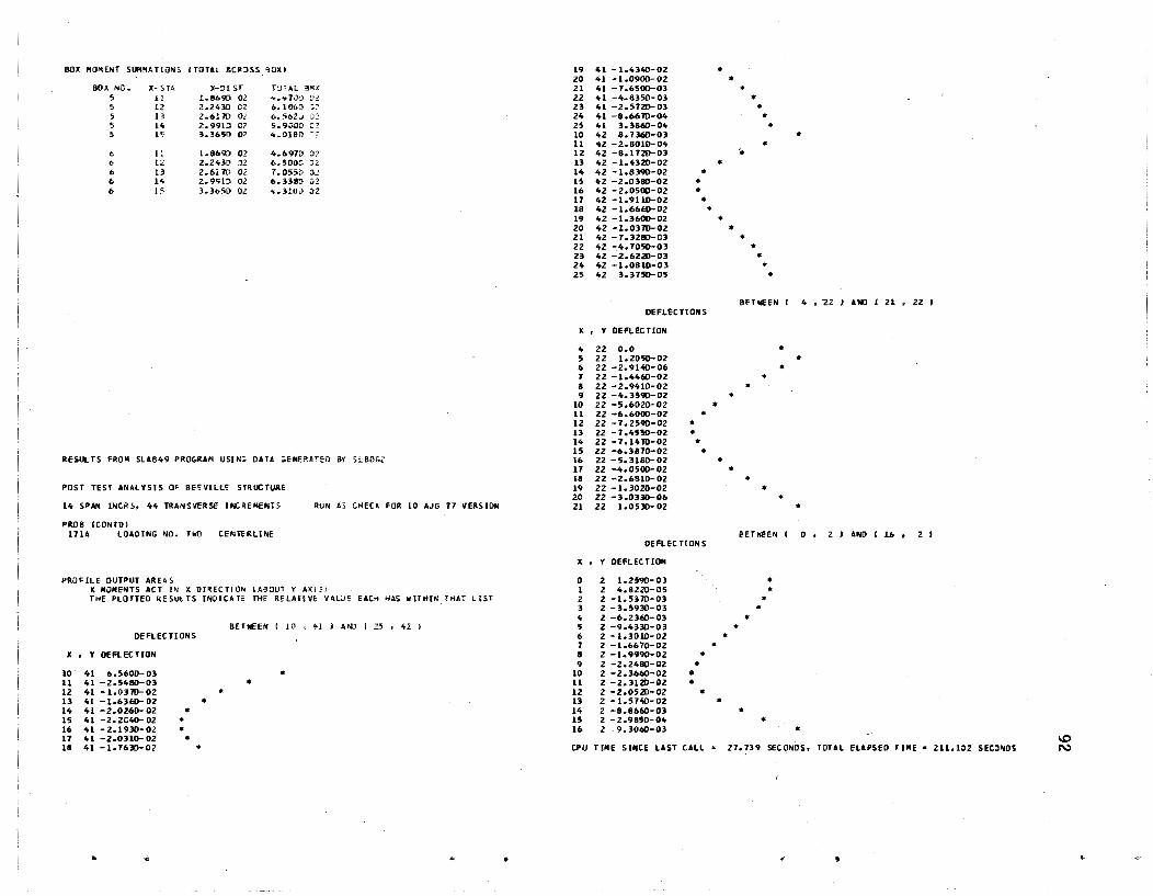
BOX HO~ENT SUMMATION~ CTOTAl AC~3SS ~OXI
BOX NO. X-SU )-~I ST r:nAl 3'« S 11 1.8690 02 4.lif.l0D ;:to!: 5 12 2.2.t,.:ID 02 6.101>:1 ~~
5 13 2.617D 02 6 .. 562;) 0] 5 14 Z.99Hl G2 5.90DO .:2 5 l~ 3.3651) 02 4.0IS!)
/, II L.1I693 02 4.6911) iJ? 6 12 2.243!) O? 6 .. 500[· ')2 {, 13 2.617D 02 1 .. 055D O~ {, 14 Z.9t;;1!) Ol 6.3381) n {, 15 1.365il 02 4 .. 310) J2
RESUL TS FRO" SLAB49 PROGRAM USIN:; DATA .. ENERHED 8Y ;1.80G2
POST TEST ANALYSIS Of BEfVILlE STRUCTURE
14 SPAN INCRS. 44 TRANSVERSE INCREIlENTS
PR08 ICONTO)
RUN A, CHECK FOR LO AJG 77 VERSION
InA LOAOING 1'10. TWO CE~TERlll';E
PROFILE OUTPUT AREAS ~ 1I0llENTS ACT IN X OI~ECTlO'" IA!HlUT 'f A.r" THE PLOTTED RESULTS INDICAT" rifE RELAHVI: VALJE EACH HA. "UIfIN THAT tIST
DEFLEe nONS
x • Y DEFLECTION
10' 41 6.5600-03 11 41 -2.5480-03 12 41 - 1.(1310- 02 13 41 -1.63flO-02 14 41 -2.0260-02 • 15 U -2.2040-02 • 16 41 -2.19:10-02 • 17 41 - 2 .ono- 02 ,. 18 41 -1.763[)-02
..
BETWEEN! 10 ,"'I AND i Z, , 42 )
,. • ..
•
..
I'll 41 -1.H~-02 20 41 -1.0900-02 21 41 -1.6500-0) 22 41 -4.8350- 03 23 41 -2.5121)-03 24 41 -8.6610-04 25 41 3.3860-04 10 42 1.7360-03 11 42 -2.1010-04 12 42 -8.1121)-03 III 42 -1.021)-02 14 42 -1.8390-02 .. 15 42 - 2 .0380-02 .. 16 42 -2.0500-02 .. 17 42 -1.9110-02 .. 18 42 -1.66flO-02 I'll 42 -1.3600-02 20 42 -1.0310-02 21 42 -7.3280-03 22 42 -4.10SQ.03 23 42 -2.6220-03 24 42 -1.0810-03 25 42 3.3150-05
DEFLECTIONS
J( • Y DEFlEC nON
4 22 0.0 5 2Z I.Z0SQ.OZ 6 Z2 -Z.9140-06 J 22 -1.446O-0Z 1 22 -2.9410-02 9 22 -4.3S90-02
10 22 -5 •• 021)- 02 11 22 -6.6000- OZ 12 22 -7.2590-02 .. 13 22 -7.4550- 02 .. 14 22-7.14m-02 .. 15 22 -6.3870-02 • 16 ZZ -5.3180-02 11 22 -4.0500- 02 18 22 -2.6810-02 I'll 22 -1.3020-02 20 22 -3.0330-06 21 22 1.05:10-02
DfFLEC HONS
X • Y DEFl EC nON
o 2 1.2590-03 1 2' 4.8221)-05 2 2 -1.5170-0] 3 2 -3.5930-03 4 2 -6.23flO-O] 5 2 -9.43:10-03 6 2 -1.3010-02 7 2' -1.6670-02 8 2' -1.9990-02 9 2 -2.2480-02
10 2 -2.3660-02 11 2 -2.3120-02 12 2' - 2.0~ZO- 02 13 2 -1.57~-02 14 2 -8.8660-03 15 2 -2.9850-04 16 2 9.3060-03
• • •
•
•
..
..
.. ..
..
•
..
..
•
•
•
.. .. .. • .. ..
;.
.. .. .. .. .. SET IOEEN
.. .. ..
.. .. •
EETIlEE'l (
• .. •
•
,.
•
• •
•
4 • 22 J ANIl , Zl • 22 ,
•
•
o • 2JANOIU, 2 ,
• I.Q
CPU TillE SINCE LAST CAU % 27.739 seCONDS. TOTAL ELAPSED r I"E • 2ll.102 SECONDS N
~

.. .. .. flI
PROGRAM SLBDG2 BRIDGE 0 I VI SI ON. TEXAS DOHPT PANAK I-----TRl14 TABLE 'I. PRINTED OUTPUT LIM! TS
REVISION DATE 10 AUG 77
POST TeST ANALYSIS DF BEEVILLE STRUCTURE
14 SPAN INCR S. 44 TRANSVERSE I NCREME~rS RUN AS CHECK FOR 10 AUG 71 VERSIO~
PROB 172A LOADING NO. THREE
TABLE I. CONTROL DATA
WEST EDGE
KEEP FROM PRECEDING PROBLEM U.YES) NUM tAROS INPUT THIS PROBLEM
MULTIPLE LOAD OPTION pR INT GENERArED DA TA SKEW ANGLE
TABLE 2. CONSTANTS USING DATA FROM THE PREVIOUS PROBLEM
2
-1
1 o
o 0.3740 02
NUMBER OF SPAN INCREMENTS IN X DIRECTIDN IIIUMBER OF INCREMENTS IN Y 01 REC T! ON
T ABLE NUMBER 4 5 6
1 o
1 o
o I
INCREMENT LENGTH IN X DIRECTION (ALONG SPAN CENTERLINE) INCREMENT L ENG TH IN V 0 IREC TI ON POlSSOI'IS U TID MODULUS OF ELASTICITY
TABLE 3. BOX STIFFNESS DATA
USING DATA FROM THE PREVIOUS PROBLEM
o 2
8
o 3
'I
1 o
14 44
3.7390 01 1.2160 01 1.5000-01 6.2000 03
TYPE NO. [NCR BOX VOID SLA8 T~ICK SHEAR KEY STIFF FACTOR
0.1000-05
LONG/T. BOX INERTIAS NO. IN WIDTH DE? WIflTH TOP BOT
I 4 20.00 23.75 5. SO 5.00 MOME~T TORS IONAL 3.0'19004 1.198004
TABL E 4. BO)( ARIUINGEMENT BY TYPE NO.
USING DATA FROM THE PREVIOUS PROBLEM 1 I 1 1 1 1
TABLE 5. LOAD PATTERNS USING OATA FROM THE PREVIOUS PROBLEM
PAT X AND Y DISTANCES (OF THE LOAD PATTERNI LOS LOAD MAGNITUDE
I -170. -39.-170. 3'1. -25. -36. -25. 36. 2:;. -36. 25. 36. 6 -5.'1300 00 -5.9300 OU -1.4S5g 01 -1.4550 01 -).4550 01 -1.455001
TABLE 6. PLACEIIENTS OF LOAD PATTERNS
PAT-PLMT, x AND Y DI STANCES .OF THE STRUCTtJREJ 1 1 lH.-lIn.
TABLE 1. SUMMATION OF BOX BENDING MOMENTS
BOX SlII1 S SUM AT X-STATlOI>j NEAREST THESE X-DISTANCES 1 5 24. 1>0. 96. 132. U.8. 2 5 24. 60. '16. HZ. 11>8.
TABLE 8. PROFILE OUTPUT AREAS
OISTS FROM - THRU X '( )( y
160. 2~2. 721. 242. -38. O. 562. O. -20~.-2"2. 360.-2~2.
OEn
1 , I
1
X MOM Y MOM I1=YESI
o 0 o 0 o 0
PRIN MOM
o o o
V-OIST FROM - THRU Y V
USING DATA FROM THE PREVICUS PROBLEM -l68. -243. -12. 12. 243. 268.
SUMMAr ION OF LOADS ON STR IX TORE SUMMAT ION OF LOADS OFF STRIX TURE
-1.0060 01 O. Q
RESULTS FROM SLAB4<; PROGRAII USI t<G DATA GENERATED BY ,L6DG2
POST TEST ANALYSIS OF BEEVILLE STRUCTURE
14 SPAN INCR S, 44 TRAIIISVER SE INC REMENTS RUN AS CHECK fOR 10 AUG 77 VEPSIO~
PROB ICONTO I 172A LOADING NO. THREF wE Sf EJGE
RESUl TS--USING STIFFNESS DATA FRO ... PREVIOUS PROBLEM 110A
SLAB X MOMENT AND X TolSTING MO~ENT ACT I', THE K DIRECTION IABOUT Y AXISI Y TWISTI'IG MOME"lT -l( hI! STING MOMENT. C::'!JNTERCLOt"'~ISE BETA A!jGLeS ARe POSITIVE FqOM THE X .XIS TO THE DIRECTION OF THE LARGEST PI!NCIPAl MOMENT SLAB "ClHE~ TS ARE PER UNI T WDT"
LARGEST SETA SLAB x PRINCIPAl. x TO
SLAB X SLAB V TWISTING ,LAS LARGEH SJPPDRT X • Y OEFL 140MENT HOME NT MOMENT MOHE", MOMENT R.EACTIDH
0 44 0.0 0.0 0.0 0.0 J.O :1.0 0.0 1 44 0.0 O. C 0.0 0.0 J.O 3.0 0.0 Z 44 0.0 0.0 0.0 0.0 J.O 0.0 0.0 3 44 0.0 0.0 0.0 0.0 J.O 0.0 '0.0 4 44 0.0 0.0 0.0 O. a J.O 0.0 0.0 5 4" 0.0 0.0 0.0 0.0 l.O 3.0 0.0 6 41t 0.0 o. a 0.0 0.0 J.O ;).0 0.0 7 44 0.0 O. a 0.0 0.0 0.0 0.0 0.0 6 44 0.0 0.0 0.0 0.0 0.0 0.0 0.0 9 44 0.0 0.0 0.0 0.0 J.O 3~O- 0.0
10 It" 2.;080-03 0.0 0.0 0.0 0.0 0.0 0.0 11 44 6.6110-04 6.1880-01 4.5630-17 1.5610 00 1.'10-'0 30 39.4 -2.'18'10 03 12 44 -7.5790-04 8.5040-01 -1.9010-11 -4.J570-02 3.5270-J\ -2.9 2.18'10 03 13 44 -1.5880-03 7.596~-01 -5.1090-17 -0.70ZD-02 1.6HO-ol -5.0 0.0 1/0 44 -1.8'130-03 5.9550-01 -7.17"0-17 -'1.5510-02 ~.10"D-01 -:8.9 0.0 15 44 -1.7860- 03 ,. '161D-OI -6.'1940-17 -1.1070-31 ".21t'l0-01 -14.6 0.0 16- 4t, -1.t,05O-03, 1.9860-01 -5.1~j)-17 -l.lbSll-Gl l.52~D-!) 1 -24.11 0.'0
.'
1.0 W

11 44 -8.8700-04 2.7890-02 -2.9530-17 -1.i590-01 1.3070-01 -41.6 0.0 1 41 0.0 0.0 0.0 0.0 J.O 0.0 0.0 18 44 -3.4930-04 -1.0110-01 -6.3440-18 -1.1140-01 -1.7330-01 32.7 0.0 8 41 0.0 O.G 0.0 0.0 J.O 0.0 0.0 19 44 1.1800-04 -1.8440-01 1.3710-17 -1.0480-01 -2.3180-Jl 24.3 0.0 'i 41 3.3390-03 0.0 0.0 0.0 J.O 0.0 0.0 20 44 4.5180-04 -2.2150-01 2.S050-17 -9.7440-02 -2.5820-01 2a.7 0.0 10 41 1.3930-03 -1.4900,-11 -2.3320-01 1.0590.00 -1.182000 -48.1 -2.4140 03 21 44 6.4430-04 -2.11140-01 3.5530-11 _9.0430-02 -2.5180~01 19.8 0.0 11 41 -5.4140-04 1.4880 00 -5.4890-~1 8.2140-02 1.4910 00 2.3 2.ItlSD 03 22 44 6.7910-04 -1.8970-01 3.6200-11 -8.4090-02 -2.2160-Jl 2l.8 0.0 12 41 -1.9220-03 1.7340 00 -1.0260-01 -3.3300-01 1.1930 00 -10.0 0.0 23 44 5.8210-04 -1.4410-01 3.0980-17 -7.7830-02 -1.7810-01 23.6 0.0 13 41 -2.6840-03 1.5410 00 -4.2640-02 -4.0290-01 1.638D 00 -13.5 0.0 24 44 3.8650-04 -8.9300-02 2.1320-11 -6.9110-JZ -1.2690-01 28.6 0.0 14 41 -2.9001)-03 1.1900 00 -2.4030-02 -4.1930-01 1.3200 00 -17.3 0.0 25 44 1.2860-04 -2.6260-02 8.9750-1S -4.0330-02 -5.5550-02 36.0 -4.2590 02 15 41 -Z.6930-03 1.7820-01 -1.2410-02 -4.0790-01 9.5090-01 -22.9 0.0 26 44 -1.4750-04 -2.35~D-16 -3.7090-18 -6.1S90-03 - •• 1890-G3 45.0 4.2590 02 16 41 -2.2110-03 3.1140-01 -4.3700-03 -3.7820-01 ~.1010-Gl -31.6 0.0
11 41 -1.595D-03 3.4710-02 1.0640-03 -3.3790-01 3.5620-01 -43.6· 0.0 0 43 0.0 0.0 0.0 0.0 l.O 0.0 0.0 16 41 -9.6130-04 -2.2260-01 4.3890-03 -2.93SD-Ol -4.241D-ol 34.4 0.0 1 43 0.0 0.0 0.0 0.0 0.0 0.0 0.0 19 41 -4.1830-04 -3.8470-01 6.1380-03 -2.5130-01 -5.0760-01 26.1 0.0 2 43 0.0 0.0 0.0 0.0 J.O 0.0 0.0 20 41 -.5.45S0-06 -4.5420-01 10.7530-03 -2.1490-01-5.3880-01 21.5 0.0 3 43 0.0 0.0 0.0 0.0 0.0 0.0 0.0 Zl 41 2.4650-04 -4.4460-01 6.643~-03 -1.8900-01 -5.1330-01 20.0 0.0
" 43 0.0 0.0 (l.0 0.0 0.0 0.0 0.0 22 41 3.4090-04 -3.8090-01 6.9160-03 -1.7600-01 -4.4890-01 21.1 0.0 5 43 0.0 0.0 0.0 0.0 l.O 0.0 0.0 23 41 3.0030-04 -2.9040-01 1.Z360-02 -1.7430-01 -3.6990-01 24.5 0.0 6 43 0.0 0.0 0.0 0.0 a.o 0.0 0.0 24 41 1.5640-04 -1.9590-01 1.1160-02 -1.41020-01 -2.5880-01 23.6 -2.711002 7 43 0.0 0.0 0.0 0.0 0.0 0.0 0.0 25 41 -6.0380-05 -1.2510-01 1.5950-01 -1.0260-01 1.9261)-01 -12.1 2.6970 02
8 43 0.0 0.0 0.0 0.0 3.0 0.0 0.0 26 41 -3.2950-04 0.0 0.0 0.0 3.0 3.0 0.0 9 43 4.0420-03 0.0 0.0 0.0 a.o ·0.0 0.0
10 43 2.1730-03 -8.5980-12 -6.54~0-02 2.4430 00 -2.4160 00 -45.4 0.0 0 Z3 0.0 0.0 0.0 0.0 3.0 3.0 0.0 11 43 3.0670-04 1.26~ 00 -1.1690-01 5.3530-02 1.2110 00 2.2 -1.4880 03 1 23 0.0 0.0 0.0 0.0 l.D l.O ,).0
LZ 43 -'1.1050-03 1.6630 00 -8.9930-02 -S.6S30-oZ 1.6610 00 -2.8 1.4890 03 2 23 0.0 0.0 0.0 0.0 3.0 0.0 0.0 13 43 -1.9241)-03 1.5060 00 -4.2000-02 -1.5110-01 1.5200 00 -5.5 0.0 3 23 0.0 0.0 0.0 0.0 3.0 3.0 0.0 14 43 -2.2080-03 1.1760 00 -2.4190-02 -2.1070-01 1.212000 -9.7 0.0 4 23 0.0 0.0 0.0 0.0 ).0 3.0 0.0
15 43 -2.0160-03 1.7950-01 -1.2650-02 -2.4110-01 8.4740-01 -15.7 0.0 5 23 1.3540,..02 0.0 0.0 0.0 3.0 0.0 0.0 16 43 -1.6680-03 3.8890-01 -10.5320-03 -2.5140-01 5.1140-01 -26.0 O~O 6 23 2.6320-0~ -3.3130-11 -5.6010 00 5.3650 00 -8.9530 )0 -58.8 -1.2210 04 11 43 -1.1220-03 5.2100-02 9.2SS0-04 -2.41>10-01 2.1450-01 -42.0 0.0 1 . 2~ -1.9930-03 6.0430 00 -2.6010 GO 3.4130 00 7.2280 00 19.1 1.2310 04 IS 41 -5.5120-04 -2.0300-01 4.2840-03 -2.332D-Ol -3.5450-01 33.0 0.0 8 23 -1.6350-02 6.9320 00 -5.2130-01 2.1180 00 7.5210 00 15 .1 0.0 19 43 -6.4660-05 -3.6550-01 6.0500-03 -2.1540-01 -4.6410-01 24.6 0.0 9 23 -2.2Z~D-02 7.0510 00 -2.5180-01 2.5350-01 7.061>0 )!) 2.0 0.0
20 43 2.9831)-04 -4.3180-01 6.6770-03 -1.9660-01 -5.1230-01 20.1 0.0 10 23 -2.5600-02 6.5110 DO -1.6940-01 -1.4640 00 ~.8810 00 -H.1 0.0 21 43 5.0620-04 -4.3310-01 6.6130-03 -1.7930-01 -4.9100-01 19.6 0.0 11 23 -2.6640-02 5.5510 00 -1.0760-01 -2.8300 00 > .1290 lO -22.5 0.0 22 43 5.6071)-04 -3.7440-01 6.6310-03 -1.6470-01 -4.3510-01 20.4 0.0 12 23 -2.5710- 02 4.2190 00 -5.95100-02 -3.758000 &.4040 00 -33.2 0.0
23 43 4.8250-04 -2.8530-01 7.1S60-03 -1.5150-01 -3.4950-01 23.0 0.0 13 23 -2.32SO-02 2.7110 00 -2.1750-0" -4.2470 ()O 5.8490 00 -35.9 0.0 24 43 3.03LD-04 -1.8000-01 1.3610-02 -1.3160-01 -2.5140-01 21.4 0.0 14 23 -109870- OZ 1.3930 00 $.2·790-03 -4.3460 00 5.1020 00 -40.' 0.0 25 4~ 5.9290-05 -1.1130-02 6.8()00-02 -7.1540-02 -1.0570-01 24.1 -2.8770 02 15 23 -1.5910-02 109040-01 3.6190-02 -4.1250 00 4.2390 00 -44.5 0.0
26 43 -2.1310-0" 2.3680-13 2.8130-02 -1.1610-02 3.2340-)2 -73.2 '2.8710 02 16 23 -1.2010-02 -1.4230-01 6.4010-02 -3.6640 00 -4.0250 )0 101.9 0.0 17 Z3 -8.3080-03 -1.3440 00 9.4150-02 -3.01080 DO -3.7510 lO 38.4 0.0
0 4Z 0.0 0.0 0.0 0.0 0.0 0.0 0.0 18 23 -5.0810-03 -1. 58~ 00 1.3020-01 -2.3800 00 -3.2600 )0 35.1 0.0 1 42 0.0 0.0 0.0 0.0 3.0 0.0 0.0 19 23 -2.4350-03 -1.513) 00 1.1350-01 -1.6660 00 -2.1180 )0 32.8 0.0
2 42 0.0 0.0 0.0 0.0 o.a 0.0 0.0 20 23 -3.2640-04 -2.1550 00 5.S910-01 -S.3970-01 -2.~920 O~ 15.7 1.5210 03
3 42 0.0 0.0 0.0 0.0 J.O 0.0 0.0 21 23 9.9030-04 1.1640-13 .2.S280-01 1.3620 00 1.5110 00 48.0 -1.5250 03
4 42 0.0 0.0 0.0 0.0 0.0 J.O 0.0 2Z 23 2.2930-03 0.0 0.0 0.0 J.O 0.0 0.0
5 42 0.0 0.0 0.0 0.0 ).0 0.0 0.0 23 23 0.0 0.0 0.0 0.0 J.O J.O 0.0 6 42 0.0 0.0 0.0 0.0 ).0 0.0 0.0 24 23 0.0 0.0 C.O 0.0 J.o ).0 0.0
1 42 0.0 0.0 0.0 0.0 0.0 0.0 0.0 25 23 0.0 0.0 0.0 0.0 J.O J.O 0.0
8 42 0.0 0.0 0.0 0.0 a.:) 0.0 0.0 26 23 0.0 0.0 0.0 0.0 a.o 300 0.0 9 42 3.1340-03 0.0 0.0 0.0 0.0 0.0 0.0
10 102 1.8350-03 -1.0250-12 -1.0820-01 1.5950-01 -2.2250-01 -54.4 -3.5360 02 0 22 0.0 0.0 0.0. 0.0 J.O 0.0 0.0
11 42 -5.86(1)-05 1.3930 00 -1.14Z0-01 8.2~20-a2 1.3980 JO 3.1 3.5240 02 1 22 0.0 0.0 0.0 0.0 0.0 0.0 0.0
12 42 -1.4640-03 1.1200 00 -9.3400-02 -1.9190-01 1.140000 -6.0 0.0 2 2Z 0.0 0.0 0.0 0.0 J.O 0.0 0.0
13 42 -2.26q1)-03 1.5590 00 -6.4900-02 -2.7620-01 1;6040 00 -9.4 a.o 3 22 0.0 0.0 0.0 0.0 J.O 0.0 0.0 14 102 -2.5300-03 1.2120 00 -10.2120-02 -3.1480-01 1.281030 -13.3 0.0 4 22 0.0 0.0 0.0 0.0 J.O 0.0 0.0
15 42 -2.3710-03 7.99'i1l-01 -2.5020-02 -3.2460-01 ~.1230-0l -19.1 0.0 5 22 1.10230-02 .0.0 0.0 0.0 J.O 0.0 0.0 16- 42 -1.9320-03 3.9560-01 -1.2510-02 -3.141D-Ol 5.6660-01 -2a.5 0.0 b 22 3.2680- 06 9.1800 00 -9.41050-01 4.5950 00 1.0950 )! 21.1 -2.0260 01
11 42 -1.3570-Q3 4.8330-02 -3.8550-03 -2.9230-01 3.1570-01 -42.4 0.0 7 22 -1.1000-02 6.5680 00 -8.8370-01 2.4130 00 7.2820 00 16.5 0.0
IS 42 -7.6380-04 -2.1380-01 1.9360-03 -2.6350-01 -3.9010-01 33.9 0.0 8 22 -1.9680-02 1.6300 00 -6.2930-01 1.071000 1.1600 OJ 1.3 0.0 19 42 -2.1t520-04 - 3. 8030-01 5.5520-03 -2.3340~01 ~.9010-01 25.2 0.0 9 22 - 2. 5690- 02 7.7860 00 -4.3300-01 -4.9310-01 7.8150 00 -3.4 0.0
20 42 1.4150-04 -It. 5360-01 7.10S0-03 -2.0580-01 -5.3210-01 2a.9 0.0 10 22 -Z.89q1)-02 7.2190 00 -2.9210-01 -2.0290 00· 1.7320 00 -14.2 0.0 21 42 3.7010-04 -4.4150-01 9.1410-03 -1.S420-01 -5.1250-01 19.4 0.0 11 22 -2.9170-02 6.0440 00 -1.S860-01 -3.28bO ~o 7.4560 00 -23.J 0.0 22 42 4.4461>-04 -3.8620-01 1.0160-02 -1. 7020-01 -~.4920-01 20.3 0.0 12 22 -2.8440-02 4.5310 00 -1.0910-01 -4.1350 00 ~.9520 00 -30.4 0.0
23 42 3.8410-04 -2.9460-01 1.3410-02 -1.6060-01 -3.6310-01 23.1 0.0 13 22 -2.5541>-02 2.9220 00 -4 •• 510-02 -4.5~50 00 !t.2390 00 -36.0 0.0
24 42 2.2100-04 -1.8560-01 1.1040-02 -1.372D-OI -2.54S0-01 26.8 -4.2600 01 14 ZZ -2.1630-02 1.3940 00 5.6790-03 -4.6260 00 >.3110 30 -43.7 0.0
25 42 -1.2010-06 -1.1990-01 1.3180-02 -4.9130-02 -1.3640-31 18.4 10.3290 01 IS 22 -1.7230-02 7.5960-02 ~.3360-02 -4.3810 00 4.4SUI 33 -44.9 0.0 26 42 -2.7161>-04 2.0nO-14 1.3230-02 -3.3210-01 3.3930-01 -'45.6 0.0 16 22 ~1.2820-02 -9.3900-01 1.0260-01 -3.9320 00 -4.3840 00 41.2 0.0
17 22 -8.1280-03 -1.5850 00 1.603D-OI -3.3530 00·-4.1710 00 37.7 0.0 0 41 0.0 0.0 0.0 0.0 a.o 0.0 0.0 18 22 -5.1910-03 -1.8280 00 2.3490-01 -2.1350 00 -3.7200 00 34.7 0.0 1 41 0.0 0.0 0.0 0.0 0.0 0.0 0.0 19 22 -2.3110-03 -1.6160 00 3.2480-01 -2.0470 00 ~2.911D 30 32.' 0.0 2 41 0.0 0.0 0.0 0.0 3.0 0.0 0.0 20 2Z .-1.6290-06 -2.6140 00 2.~59O-01 -1.5490 00 -3.3350 )0 23.' 1.0100 01 3 41 0.0 0.0 0.0 0.0 0.0 0.0 0.0 21 22 1.3670-03 0.0 0.0 0.0 3.0 J.O 0.0 4 41 0.0 0.0 0.0 0.0 0.0 0.0 0.0 22 2Z 0.0 0.0 0.0 0.0 3.0 0.0 0.0 5 41 0.0 0.0 0.0 0.0 3.0 0.0 0.0 23 22 0.0 0.0 0.0 0.0 ).0 0.0 0.0 \D 6 41 0.0 0.0 0.0 \).0 3.0 0.0 0.0 24 22 0.0 0.0 0.0 0.0 0.0 3.0 0.0 ~
" '" .. .. " ~.

" '" .. III .. ,.
25 22 0.0 0.0 0.0 0.0 3.0 0.0 0.0 15 2 -5.6350-04 7.2310 00 6.5130-01 -1.6~10 00 -1.5610 JO 11.3 3.3850 03 26 22 0.0 0.0 0.0 0.0 3.0 a.o 0.0 16 2 1.1450-02 -2.6610-13 6.1920-01 -9.3150-01 1.2910 JO -54.1 -3.364003
17 2 3.5440-02 0.0 0.0 0.0 J.O a .0 0.0 0 21 0.0 0.0 0.0 0.0 J.O 0.0 0.0 18 .2 0.0 0.0 0.0 0.0 loO :l.0 0.0
1 21 0.0 0.0 0.0 0.0 3.J 0.0 0.0 19 2 0.0 0.0 0.0 0.0 0.0 :l.0 0.0 .2 21 0.0 0.0 0.0 0.0 l.O 0.0 0.0 20 2 0.0 0.0 0.0 0.0 0.0 0.0 0.0 3 21 0.0 0.0 0.0 0.0 l.O 0.0 0.0 21 2 0.0 0.0 0.0 0.0 3.0 0.0 0.0 4 21 2.5290-02 c.o 0.0 0.0 0.0 0.0 0.0 22 2 0.0 O. a 0.0 0.0 l.O 0.0 0.0
5 21 1.0830- 02 - 5. 6260-11 -9.1080-01 1.6110 01 -1.6600 01 -45.9 -1.6680 04 23 2 0.0 0.0 0.0 0.0 J.O 0.0 0.0
6 21 -3.5840-03 8.4880 00 - 2. 0450 00 1.6430 00 8.B80 )0 8.1 1.6100 04 24 2 0.0 0.0 0.0 0.0 ).0 0.0 0.0 1 21 -1.4890- 02 1.1050 00 -5.0060-01 1.5900 00 1.4250 aD 11.3 0.0 25 2 0.0 0.0 0.0 0.0 0.0 0.0 0.0 8 21 -2.3610-02 1.9280 00 -3.4480-01 1.2190-01 1.9300 00 0.9 0.0 26 2 0.0 0.0 0.0 0.0 l.O 0.0 0.0 9 21 -2.9620-02 8.1060 00 -2.479{)-01 -1.2260 00 9.282000 -8.2 0.0
10 21 -3.269!l-02 1.51eo 00 -1.7210-01 -2.5980 00 8.306000 -11.0 0.0 0 1 1.3990- 02 - 5. 0180-12 9.1630-01 -3.94~0-01 1.063000 -69.6 -1.8860 04
11 21 -3.3100-02 6.2440 00 -1.0890-01 -3.1480 00 1.9810 ao -24.9 0.0 I 1 -3.8820-03 -2.1530 00 2.2960 00 -2.8140 00 3.6580 )0 -6".2 1.8840 04
12 21 -3.130D-02 4.6270 00 -5.8890-02 -4.5180 00 1.3730 00 -31.3 0.0 2 1-2.2630-02 -1.9081) 00 5.6900-01 -5.2690 00 -~.0820 00 38.4 0.0 13 2 I -2.7860- 02 2.Q250 00 -2.0250-02 -4.8890 00 6.5590 00 -36.6 0.0 3 I -4.2090-02 9.9680- 01 3.098v-01 -6.0440 00 6.1070 )0 -43.4 0.0 14 21 -2.3390-02 1.3230 00 1.1180-02 -4.9100 00 5.6210 00 -41.2 0.0 " I -6.1210-02 5.158!l 00 1.186D-01 -6.4520 00 9.5840 00 -34.5 0.0
15 21 -1.8440- 02 - 4.1030- 02 3.8910-02 -4.6520 00 ~.6560 O~ "4.7 0.0 5 1 -1.8510-02 B.8810 00 1.1690-01 -6.5990 00 1.2420 01 -28.2 0.0
16 21 -1.3520-02 -1.0910 00 6.7020-02 -4.2020 00 -4.7540 00 41.1 0.0 6 1 -9.2680-02 1.1640 01 1.3010-01 -6.1620 00 1.4110 DI '-24.8 0.0 17 21 -8.9860-03 -1.1400 00 1.0390-01 -3.6650 00 -4.5910 00 31.9 0.0 1 I -1.0210-01 1.4900 01 1.0840-01 -1.00~0 00 1.7690 01 -21.1 O~O
18 21 -5.0720-03 -1.9150 00 2.2120-01 -3.1710 00 -4.2330 00 35.4 0.0 8 1 -1.0150-01 1.8680 01 5.6200-03 -6.9990 00 2.1010 )1 -18.4 0.0 19 21 -1.861D-03 -1.8500 00 1.2230 00 -2.3630 00 -3.1320 00 28.5 2.8160 03 9 1 -1.057!l- 01 2.0200 01 -3.9440-02 -6.6610 00 2.22)0 01 -16.1 0.0 20 21 6.2210-04 6.9360-12 2.7660 00 -1.9180 JO 3.7480 30 -62.9 -2.8990 03 10 1 -9.6190-02 1.8330 01 -3.5050-02 -6.2180 ~O 2.0240 J1 -11.1 0.0
21 21 2.9710-03 0.0 0.0 0.0 J.O 0.0 0.0 11 1 -8.1360-02 1.2640 01 1.1160-01 -6.0830 00 1.5100 01 -22.1 0.0 22 21 0.0 0.0 0.0 0.0 J.O 0.0 0.0 12 1 >-6.1410-02 1.08'lO 00 1.6930-01 -6.2970 00 1.081001 -30.6 0.0 23 21 0.0 0.0 0.0 0.0 ).0 0.0 0.0 13 1 -3.9080-02 1.4000 00 3.1630-01 -6.3950 00 1.2110 00 -42.6 0.0
24 21 0.0 0.0 0.0 0.0 l.O 0.0 0.0 14 1 -1.6210-02 -5.8020 00 1.8100 00 ~4.IIOO 00 -1.5970 00 23.6 2.1850 04
Z5 21 0.0 0.0 0.0 0.0 l.O 0.0 0.0 15 I 4.5100-03 -6.6010 00 4.1190 00 -9.5340-01 ~.6850 00 5.0 -2.1880 04
26 21 0.0 0.0 0.0 0.0 J.o ~.O 0.0 16 I 2.2690-02 1.108!l-14 4.2180-01 2.5100 01 2.5320 01 45.2 0.0 17 I 4.0850-02 0.0 0.0 0.0 J.O 0.0 0.0
0 20 0.0 0.0 0.0 0.0 0.0 0.0 0.0 18 I 0.0 0.0 0.0 0.0 J.O 0.0 0.0
1 20 0.0 0.0 0.0 0.0 J.O J.>o 0.0 19 1 0.0 0.0 0.0 (J.O ~.O 0.0 0.0
2 20 0.0 0.0 0.0 0.0 J.O 0.0 0.0 20 1 0.0 0.0 0.0 0.0 J.J 0.0 0.0
3 20 0.0 0.0 0.0 0.0 J.O 0.0 0.0 21 1 0.0 0.0 0.0 0.0 J.~ 0.0 0.0 4 20 2.2010-02 0.0 0.0 0.0 J.O 3.0 0.0 22 I 0.0 0.0 0.0 0.0 0.0 0.0 0.0
5 20 1.3910-03 -6.0130-14 -3.0b60-0b 4.676000 -4.6760 lO -45.0 -2.2110 04 23 I 0.0 0.0 0.0 0.0 3.0 0.0 0.0
6 20 -1.2890-03 9. 0420 00 -6.6200-06 3.2110 30 1.0010 01 11.1 2.2140 04 24 I 0.0 0.0 0.0 0.0 J.3 0.0 0.0
7 20 -1.8840-02 1.7860 00 -1.45)0-05 2.3830 00 8.4510 lO 15.7 0.0 25 I 0.0 0.0 0.0 0.0 3.0 0.0 0.0
8 20 -2.1100-02 8.5780 00 -1.8650-05 5.6130-01 8.6150 00 3.1 0.0 26 1 0.0 0.0 0.0 0.0 3.0 0 J .0 0.0
9 20 -3.3590-02 8.1930 00 -2.0130-05 -1.2380 00 9.9640 lO -7.9 0.0 10 20 - 3.6450- 02 8.1420 00 -1.9000-05 -2.9660 00 9.1070 00 -18.0 0.0 0 0 9.4810-03 -1.2540-14 -3.9180-20 -2.29bO-01 -2.2960-01 45.0 -2.7380 04
11 20 -3.6480-02 6.1200 00 -1.6090-05 -4.354000 9.8600 00 -2b.2 0.0 I o -8.2670-03 -7.0120-01 5.6050-20 -1.41;0 00 -1.8120 )0 38.0 2.1380 04
12 20 -3.4190-02 4.9230 00 -1.2160-05 -5.2450 00 9.2550 00 -32.4 0.0 2 0-2.6500-02 -8.3130-01 1.121:>-19 -2.522000 -2.972000 40.3 0.0
13 20 -3.0200-02 3.0510 00 -7.1890-06 -5.6410 00 7.3740 00 -37.4 0.0 3 o -4.5320-02 5.8290-01 2.835D-l~ -2.9230 00 3.2290 JO -42.2 0.0
14 20 -2.5150-02 1- 3030 00 -3.4370-06 -5.6250 00 S.3140 00 -41.7 0.0 4 o -6.3730- 02 2.6620 >00 5.2050-i~ -3.1240 00 '.1Z10 n -33.5 00.0
15 20 -1.9650-02 -1.8060-01 5.0190-01 -5.2620 00 -5.3530 00 44.5 0.0 5 o -8.0290-02 4.5410 00 4.0800-19 -3.2190 aD ~.2150 )0 -27.4 (l.0
16 20 -1.4220-02 -1.2990 00 3.6810-06 -4.6480 00 -5.3430 00 41.0 0.0 6 o -9.31l!l-02 5. 'l1'lO 00 5.1800-19 -3.3080 00 1.4480 00 -23.9 0.0
11 20 -9.2310-03 -1- 9740 00 5.1110-06 -3.8800 00 -4.990000 37.9 0.0 7 0-1.0300-01 7.6400 DO 3.,980-19 -3.4130 00 8.9430 JO -20.9 0.0
18 20 -4.9280-03 -2.1510 00 6.0600-06 -3.0980 00 -~.35'0 00 35.4 0.0 8 0-1.0100-01 9.5110 00 4.4220-19 -3.4310 00 1.0~20 H -17.9 0.0 19 20 -1.3690-03 -2.4450 00 3.5240-06 -2.2460 00 -3.7800 00 30.7 4.2160 03 9 o -1.0440-01 1.0270 01 ).3290-19 -3.331~ VO 1.1260 n -16.5 0.0 20 20 1.3450-03 -1.0500-14 2.5750-06 -9.9040-01 9.9040-)1 -45.0 -~.1940 03 10 o -9.4130-02 ~.noo 00 3.7990-19 -3.2050 00 1.0310 J1 -11.3 0.0
21 20 4.0580- 03 0.0 0.0 0.0 J.O ~.O 0.0 11 o -1.8600-02 6.4180 00 4.4530-19 -3.1S4D 00 7.7810 ao -22.3 0.0
22 20 0.0 0,0 0.0 o. a 0.0 0.0 0.0 12 a - 5.1990-02 3.6500 00 4.14)0-19 -3.2910 00 5.589030 -3:>.5 0.0 2) 20 0.0 0.0 0.0 0.0 J.O 3.0 0.0 13 o -3.4850-02 1.2820-01 3.2610-19 -3.4280 00 3.8110 ~J -42.0 0.0 24 20 0.0 0.0 0.0 0.0 3.0 0.0 0.0 14 0-1.1210-02 -3.84'lO 00 6.1480-20 -2.3)80 30 -~.9300 00 25.1 3.2380 04
25 20 0.0 0.0 0.0 0.0 ::l.0 0.0 0.0 15 0 9.7660-03 -4.0400 00 -4.5140-20 1.796001 -2.039001 -41.8>-3.234004
2b 20 D.O 0.0 0.0 0.0 J.O 0.0 0.0 16 0 2.794!l-02 0.0 0.0 0.0 J.3 0.0 0.0 17 0 0.0 0.0 0.) 0.0 J.O 0.0 0.0
0 2 1.85~-02 -1.1120-13 4.3530-01 2.2610 01 2.2830 at 45.3 0.0 18 0 0.0 0.0 0.0 0 ... \.1 J.O l.O 0.0
1 2 5.9650-04 -3.9480 00 4.4290-01 -1.1130 00 -~.5140 00 19.5 -).5830 0) 19 0 0.0 0.0 0.0 0.0 J.O J.O 0.0
2 2 -1.8130-02 -2.1960 00 6.3880-01 -5.4010 00 -6.)620 aD 31.6 3.6100 03 20 0 0.0 0.0 0.3 0.0 J.O J.O 0.0 ) 2 -3.885!l-02 8."810-01 4.9910-01 -6.8010 00 1.418000 -44.3 0.0 21 0 0.0 0.0 0.3 0.0 J.O 0.0" 0.0
4 2 -5.871D-02 5.2310 00 3.1590-01 -1.098000 1.031031-35.6 0.0 22 0 0.0 0.0 0.0 0.0 J.O 0.0 > 0.0
5 2 -1.6170-02 9.0820 00 2.9010-01 -1.0630 00 1.3010 01 -29.1 0.0 23 0 0.0 0.0 0.0 0.0 J.o J.O 0.0
6 2 -9.1100- 02 1.1810 01 2.3140-01 -1.1100 00 1.5190 01 -25.4 0.0 24 0 0.0 0.0 0.0 0.0 J.O J.O 0.0
1 2 -1.0U.o-01 1.5150 01 1.9430-01 -1.3160 00 1.8130 0 I -22.2 0.0 25 0 0.0 0.0 0.0 0.0 0.0 3.0 0.0
8 2 -1.0820-01 1.nlX> 01 1.6930-01 -7.2010 00 2.1620 01 -18.6 0.0 26 0 0.0 0.0 0.0 0.0 J.O J.O 0.0
9 2 -1.0120-01 2.0830 01 1.6590-01 -6.62~0 00 2.2710 01 -16.) 0.0 10 2 -9.8950-02 1.891i0 01 1.8700-01 -5.8550 00 2.0&20 H -16.0 0.0 11 2 -8.4180-02 1.285D 01 2.4480-01 -5.4920 00 1.4910 01 -20.5 0.0
12 2 -6.4960-02 7.1940 00 3.2990-01 -5.5350 00 1.0210 01 -29.1 0.0 STATICS CHECK. SUMMATI0~ OF REACTIONS ~ 7.00100 01
13 2 -4.3310-02 1.5450 00 ".1110-01 -5.2200 00 l>.2560 )0 -42.1 0.0 1..0 14 2 - 2.1120-02 -4.5991) 00 6.8130-01 -3.2210 00 -10.122030 25.3 0.0 MAXIMUM STATICS CHECK ERROR AT STA 9 12 • -6.ll!6D-09 c..n

BOX MOMENT SUMMA TlONS I TOTAL ACROSS BOXl
BOX 1110. X-STA X-OI ST fOTAL BMX 1 7 3.7390 01 7.2920 02 1 8 7.4780 01 9.268D n 1 9 1.1220 02 1.0060 03 1 10 1.4960 02 9.1650 02 1 10 1.4960 02 0.0
2 7 3.7390 01 6.9'920 02 2 8 7.4780 01 8.9250 02 2 9 1.1220 02 9. noD 02 2 10 1."960 02 8.8640 02 2 10 1.4960 02 0.0
RESUL TS FROM SLAB4Q PROGRAM USI N:; DATA GENERATED 8V H80G2
POST TEST ANAL TSfS OF· 8EEVILLE STRUCTURE
14 SPAN INCRS. 44 TRANSVERSE INCREMENTS RUN AS CHECK FDR 10 AUG 77 VERSIO~
PROS ICONTO I 172A LOADING 00. THREE WE S T EDGE
PROFILE DUTPUT AREAS X MOMENTS AC T IN X OfREC TlON I ASOUT Y AX! 51 THE PLOTTED RESULTS 1III0IeATE THE RELATIVE VALUE EACH HAS wlfHIN THAT LIST
OEFLEC nONS
x • Y DEFLECTION
10 41 1.3930- 03 11 41 -5.4140-04 12 41 -1.9220-03 13 41 -2.6840-03 14 41 -2.9000-03 .. l' U -2.6930-03 • 16 41 -2.2110-03 17 41 -1.5950- 03 18 "1 -9.6'30-04
..
BETWEEN I 10 • 41 I AND I 25 • 42 I
.. .. ..
.. ..
•
19 Itl -4.1830-04 20 It1 -5.4580- 06 21 41 2."650-04 22 41 3.4090-0" 2! 'II 3.0030-0'1 Z4 41 1.5640- 0'1 25 41 -6.0380-05 10 42 1.8350-03 11 42 -5.8660-05 12 42 -1.4640-03 13 "2 -2.2690-03 14 "2 -2.5300-03 .. 15 '12 -2.3710-03 • 16 "2 -1.9320-03 17 42 -1.3570-03 18 42 -7.6380-0" 19 42 -2.452O-0lt 20 42 1.4150-04 21 42 . 3.7070-04 22 42 4."460-010 23 42 3.8410-0" 24 42 2.2100·04 25 42 -7.2070-06
OEFLEC HON S
It • Y OEFL ec TlON
4 22 0.0 5 22 1.4230-02 6 22 3.2680-06 7 22 -1.1000-02 8 22 -1.9680-02 9 22 -2.5690-02 ..
10 2Z -2.8990-02 .. 11 22 -2.9770-02 .. 12 22 -2.8440-02 .. 13 22 -2.5540- 02 .. 14 2Z -2.1630-02 15 22 -1. 7Z30- 02 10 22 -1.2820-02 17 22 -8.7280- 03 18 22 -5.1970-03 19 Z2 -2.3110-03 20 22 -1.6290-06 21 22 1.3670-03
OEFLEC TICINS
X • Y DEFLECTION
o 2 1.8540-02 1 2 5.9650-04 2 2 -1.8730-02 3 2 - 3 .8850- 02 " 2 -5.8110-02 5 2 -7.6770-02 6 2 -9.1700-02 7 2 -1.0260-01 8 2 -1.0820-01 9 2 -hOnO-OI
10 2 -9.8950-02 11 2 -8.4180-02 12 2 -6.4980-02 13 2 -4.3110-02 14 2-2.1120-02 15 2 -5.6150-04 16 2 1.7450-02
.. .. ..
.. ..
CPU TIlliE SINCE LAST CALL
• ..
..
..
..
..
..
..
..
..
.. .. .. .. .. .. ..
.. • .. .. ..
* *
BElIEEN I
.. ..
..
..
. .. BE r wee~
.. ..
.. ..
..
4 • 22 I AND I 21 • 22 I
..
o • Z I AND! 11>. 2 I
..
.. 27.513 SECONDS. TOTAL HAP,!;£) flfo!E • 211.614 seCl.NDS
.., ..
\Q en
! •