size effect on compression strength of fiber composites ... effect on compression strength of fiber...
TRANSCRIPT

International Journal of Fracture95: 103–141, 1999.© 1999Kluwer Academic Publishers. Printed in the Netherlands.
Size effect on compression strength of fiber composites failing bykink band propagation
ZDENEK P. BAŽANT1, JANG-JAY H. KIM2, ISAAC M. DANIEL3,EMILIE BECQ-GIRAUDON4 and GOANGSEUP ZI41Walter P. Murphy Professor of Civil Engineering and Materials Science, Northwestern University, Evanston,Illinois 60208; e-mail: [email protected] Research Assistant, Northwestern University; currently Research Engineer, Sandia NationalLaboratories, Albuquerque, New Mexico3Walter P. Murphy Professor of Civil and Mechanical Engineering, Northwestern University.4Graduate Research Assistant, Northwestern University.
Received 16 July 1998; accepted in revised form 31 December 1998
Abstract. The effect of structure size on the nominal strength of unidirectional fiber-polymer composites, failingby propagation of a kink band with fiber microbuckling, is analyzed experimentally and theoretically. Tests ofnovel geometrically similar carbon–PEEK specimens, with notches slanted so as to lead to a pure kink band (notaccompanied by shear or splitting cracks), are conducted. They confirm the possibility of stable growth of longkind bands before the peak load, and reveal the existence of a strong (deterministic, non-statistical) size effect.The bi-logarithmic plot of the nominal strength (load divided by size and thickness) versus the characteristic sizeagrees with the approximate size effect law proposed for quasibrittle failures in 1983 by Bažant. The plot exhibits agradual transition from a horizontal asymptote, representing the case of no size effect (characteristic of plasticity orstrength criteria), to an asymptote of slope−1
2 (characteristic of linear elastic fracture mechanics, LEFM). A newderivation of this law by approximate (asymptotically correct)J -integral analysis of the energy release, as well asby the recently proposed nonlocal fracture mechanics, is given. The size effect law is further generalized to notch-free specimens attaining the maximum load after a stable growth of a kink band transmitting a uniform residualstress, and the generalized law is verified by Soutis, Curtis and Fleck’s recent compression tests of specimens withholes of different diameters. The nominal strength of specimens failing at the initiation of a kink band from asmooth surface is predicted to also exhibit a (deterministic) size effect if there is a nonzero stress gradient at thesurface. A different size effect law is derived for this case by analyzing the stress redistribution. The size effectlaw for notched specimens permits the fracture energy of the kink band and the length of the fracture process zoneat the front of the band to be identified solely from the measurements of maximum loads. The results indicate thatthe current design practice, which relies on the strength criteria or plasticity and thus inevitably misses the sizeeffect, is acceptable only for small structural parts and, in the interest of safety, should be revised in the case oflarge structural parts.
Key words: Fracture, compression, fiber composites, testing, kink bands, microbuckling, size effect, scaling,asymptotic analysis,J -integral, equivalent LEFM, cohesive crack model.
1. Introduction
In the early 1980’s it became clear that the size effect on the nominal strength of quasib-rittle materials failing after large stable crack growth is caused principally by energy release(Bažant 1984) and cannot be explained by Weibull-type statistics of random microdefects.Ever since, the problem of size effect has received increasing attention (see the reviews inBažant and Chen, 1997, and Bažant and Planas, 1998). Size effects caused by energy release
206427.tex; 11/05/1999; 11:04; p.1(O.S. Disc 1029) INTERPRINT: Web2c J.N.B. fracBAZ07 (frackap:engifam) v.1.1

104 Zdenek P. Bažant et al.
into a finite-size FPZ (or damage localization zone) have been extensively demonstrated andmathematically described for concrete, mortar, rocks, ceramics and sea ice. Description ofsuch a size effect requires an energy analysis of fracture mechanics type.
At present, all the textbooks and practical procedures for fiber composites characterizethe failure in terms of strength or plasticity type criteria, which are inherently incapableof capturing the size effect. Recently, though, the existence of size effect has been demon-strated by tests of notched orthotropic and quasi-isotropic carbon-epoxy laminates undertensile (Mode I) loading (Bažant, Daniel and Li, 1996). A size effect of thickness in laminateswas experimentally shown by Daniel and Hsiao (1996).
The present study will focus attention on the compression failure of unidirectionally re-inforced fiber composites. This is a particularly complex type of material failure, which caninvolve two distinct mechanisms:
(1) delamination fracture, and(2) a row of parallel axial shear cracks combined with microbuckling of fibers in a so-called
kink band.
Only the latter mechanism of failure will be considered in this study.Compression microbuckling in kink bands has been studied extensively for over thirty
years and a large body of knowledge has been accumulated. Rosen (1965) presented a simpleformula for compression strength based on the idea of buckling of parallel fibers embedded inan elastic matrix. Similar more refined formulae for elastic composites with wavy fibers werepresented by Bažant (1968). Argon (1972) extended Rosen’s formula by considering plasticyielding.
A further important refinement was introduced by Budiansky (1983) who took into accountthe initial misalignment of the axial fibers and showed its pronounced effect. Various sub-sequent refinements within the framework of elastoplastic analysis were made by Budianskyand Fleck (1993), Kyriakides et al. (1995), Christensen and DeTereza (1997), Soutis et al.(1991, 1993), Moran et al. (1995), Jelf and Fleck (1992), Fleck and Jelf (1995), Fleck andShu (1995), Fleck et al. (1996), Kyriakides and Ruff (1997), and others; see the excellentreviews by Fleck (1997), Budiansky and Fleck (1994), Schultheisz and Waas (1996), Waasand Schultheisz (1996), and Sutcliffe and Fleck (1994). These studies included the analysis ofpost-buckling behavior of the fibers, inelastic behavior of matrix, and various imperfections.They provided understanding of the factors governing the inclination of the kink band withregard to the direction of the fibers, including the role of lateral expansion in the kink bandand the shape of the assumed yield surface. Analysis of microbuckle initiation by small-scaleyielding fracture mechanics was presented by Sutcliffe et al. (1996)
None of the existing formulae for the nominal strength in compression, however, predictsany size effect. Omission of the size effect in compression has seemed natural because small-scale laboratory tests indicated no size effect and because the maximum load has been thoughtto occur at the very beginning of microbuckling, before the size or the length of the kink bandbecomes macroscopically significant.
Recently, though, various fracture mechanics aspects of the kink band failure came tolight. Based on strain measurements at the flank of the kink band, the experimental studiesof Sutcliffe and Fleck (1994) and Fleck et al. (1996, 1997) demonstrated that the axial normalstress across the band decreases with the distance from the band front, and reaches a plateauequal to about 50 percent of the maximum stress. This means that the diagram of the axialnormal stress versus the axial relative displacement across the band exhibits softening and
206427.tex; 11/05/1999; 11:04; p.2

Size effect on compression strength of fiber composites failing by kink band propagation105
then reaches a yield plateau at about 50 percent stress reduction. Such a crack-like behavior ofthe band (Fleck et al., 1996) was further confirmed by the study of Moran et al. (1995), whodiscovered the phenomenon of band broadening. In retrospect, the band broadening appearsnatural to expect because it is required to accommodate the increase of relative displacementacross the band with the distance from the front, similar (but opposite in sign) to the increaseof crack opening.
Fleck (1996) and Sutcliffe and Fleck (1996) conducted two-dimensional fracture analyses,adapting the cohesive crack model for compression, and estimated the fracture energy associ-ated with the kink band propagation. Soutis et al. (1991) reported extensive numerical studieswith a crack-bridging model and analyzed the effect of the size of a hole on the strength of acomposite specimen. They calculated and experimentally verified how the apparent strength inthe vicinity of a hole decreases with an increasing diameter of the hole. Although geometricsimilarity of the hole with the specimen dimensions was not maintained in these tests, theresults nevertheless hint at the likelihood of size effect.
Recently, Budiansky, Fleck and Amazigo (1997) analyzed the propagation of a semi-infinite out-of-plane kink band, approximating the band with a crack whose face is allowedto overlap in compression. They assumed the FPZ to be lumped into a point, and analyzingenergy balance derived the formula
σu = σb +√Gb/L (1)
in whichσu = axial normal stress ‘upstream’ in the direction of propagation (far enough aheadof the front),σb = axial normal stress transmitted across the band far enough behind the front,L = specimen height, andGb = material constant playing the role of fracture energy andconsisting of the work of sliding shear stresses in the band, the work of fiber debonding, andthe work of the axial normal stress on the relative displacement across the band. Sutcliffe etal. (1996) examined the energy release rate required for microbuckle initiation by small-scaleyielding fracture mechanics approach. required for microbuckle initiation
Although this formula does not give the effect of sizeL on the nominal strength of geomet-rically similar specimens and does not take into account the effect of the size of the FPZ at thefront of the kink band, it clearly suggests the existence of a size effect. More importantly, thetype of analysis that has led to this formula gives an inspiration for taking a fracture mechanicsapproach.
The present study, involving specimens of geometrically similar shapes, reports experi-mental results that reveal the existence a size effect in kink band compression failure andpermit an approximate calibration of size effect theory. A simplified analysis of the energyrelease, briefly outlined at a recent conference (Bažant 1998(a)), is used to obtain closed-formformulae for the size effect in failures that occur either after a large stable growth of kinkband, or at the initiation of the kink band. These formulae represent a special application ofthe general asymptotic analysis of size effect proposed for compression fracture in Bažant(1997) and Bažant and Chen (1997).
2. Size effect tests of notched specimens
The kink band failure is often combined with axial splitting-shear cracks and delaminations.Such combined failures are difficult to analyze because the contributions of the microbucklingin the kink band and of the shear, splitting and delamination failures are hard to separate.
206427.tex; 11/05/1999; 11:04; p.3

106 Zdenek P. Bažant et al.
Therefore, the objective of experimental investigation aimed at verifying a theory should beto find the type of fiber composite and the shape of specimen that would lead to a pure kinkband failure and would do so even for very large sizes.
After experimenting with various types of composites, the carbon fiber composite with aPEEK (poly-ether-ether-keton) thermoplastic polymer matrix was selected. The advantage ofPEEK is that it is less brittle than carbon epoxy composites, which leads to a more stable typeof failure. It follows that, if a size effect is revealed in this type of composite, it should existand be in fact more pronounced in more brittle composites, such as the carbon fiber-epoxycomposites.
To exclude the effect of random variation of material strength over the specimen volume(known to cause Weibull-type size effect), the specimens (shown in Figure 1(a,c) and 2) needto be provided with notches. The notches ensure the failure to begin in one desired place,preventing the failure from starting at diverse locations where the material is statisticallyweakest.
Why a one-sided notch, rather than two symmetric notches? The reason is that a bifurcationof the equilibrium path would have to be expected to occur, according to the analysis in Bažantand Cedolin (1991, Sec. 12.5). Symmetric growth of two interacting kink bands would surelyrepresent an unstable path. The stable path is a one-sided growth of one kink band even ifthere are two notches.
Notches that are orthogonal to the surface have normally been used in fracture testing.At the beginning of this study, however, such notches were found to engender failures thatbegin by an axial splitting-shear crack (Figure 1(b)), which is only later followed by thedevelopment of an out-of-plane kink band. Such a band typically has a transverse inclination(such inclination was previously observed by Fleck et al. (1996), Sutcliffe and Fleck (1994),Kyriakides et al. (1995)). For this reason, the starter notch has been made inclined (Figure 1(c),2) with the same angle as the out-of-plane kink band. This inclination was found by trial teststo be 25.4◦. It made it possible to eliminate in most tests the axial splitting-shear cracks andthus obtain pure kink band failures.
The test specimens, shown in Figure 1(a,c) and 2, are scaled in two dimensions. the thick-nessb in the third dimension being constant. The specimen dimensions and the notch depthsof the specimens of different sizes are scaled in the ratio 1:2:4. The notch of lengtha0 = 0.3 D,where D is the specimen width, is machined with a diamond bladed band saw up to 95 percentof its length. Then the notch is sharpened at the tip by a cut whose depth is 5 percent of thenotch depth. The cut is machined with a 0.2 mm diameter diamond-studded wire, and thusthe crack tip radius is 0.1 mm in all the specimens. The deptha0 of the notch considered forscaling and in the analysis includes the depth of the wire saw cut.
The content of polymer resin in the specimen (supplied by Fiberite, Inc., Orange, Cali-fornia) was 32± 3 percent. The specimens have been molded at Northwestern Universityfrom 100 plies of sheets 304.8 × 304.8 mm, 0.05 mm thick. The molding was carried outunder temperature 391◦C (735◦F) and pressure 0.69 MPa, using the standard time sequenceof the curing process. After the specimens had been cut from the molded sheets, they wereprovided with massive end caps made of 1040 hot rod steel, to which they were glued byepoxy. To ensure proper alignment, the end caps were glued only after the specimen had beeninstalled under the loading platens of the testing machine. The end plates were restrained toprevent any rotations. All the specimens have been tested under a controlled stroke rate of1.27× 10−4 mm/s. After the kink band had initiated at the notch tip, it was seen to propagatestably on both the front and back sides of the specimen. On one side, the kink band was usually
206427.tex; 11/05/1999; 11:04; p.4

Size effect on compression strength of fiber composites failing by kink band propagation107
Figure 1. (a) Geometrically similar single-edge notched carbon-PEEK (poly-ether-ether-keton) specimens tested,and scheme of loading, (b) specimen with an orthogonal notch exhibiting undesirable failure (splitting-shearcracks), and (c) transversely slanted notches used in present tests (Figures 3 and 4), achieving pure kink bandfailure.
206427.tex; 11/05/1999; 11:04; p.5

108 Zdenek P. Bažant et al.
Figure 2. Photo of three of the specimens after the test, showing the out-of-plane kink band.
slightly longer than on the other side, but only at the beginning of propagation. The shorterband on one side would soon catch up with the longer band on the opposite side.
As usual, the nominal strength of the specimen, which represents a parameter of themaximum load having the dimension of stress, is defined as
σN = P/bD, (2)
in whichP =maximum load measured,b = specimen thickness (12.7 mm (0.5 in)), andD =specimen width (chosen as the characteristic dimension). Figure 3 shows the individual testresults in the form of the plot of logσN versus logD.
Figure 4 further shows for the individual specimens the diagrams of the measured averagestress over the ligament,σL = σND/(D − a0), versus the average axial strainε determinedas the stroke of the piston divided by the length between the platens. All these load-deflectiondiagrams exhibit a post-peak stress drop rather than a horizontal yield plateau at peak load.This fact alone suffices to demonstrate that a fracture-type approach (or a nonlocal damageapproach) is required. Furthermore, these diagrams reveal the existence of a terminal yieldplateau, which confirms the existence of a finite residual stress across the kink band.
If there were no size effect, as currently assumed in design and exhibited by the existingformulae for the maximum load expressed in terms of stress or strain, the plot in Figure 3would have to be horizontal. Every theory based on plasticity or on some critical values ofstress or strain predicts a horizontal plot. However, the trend is clearly seen to be downward.The downward slope is quite steep and closer to the slope−1
2 corresponding to LEFM than
206427.tex; 11/05/1999; 11:04; p.6

Size effect on compression strength of fiber composites failing by kink band propagation109
Figure 3. Results of the present tests of nominal strength of carbon-PEEK specimens (data points) and theiroptimum fit by equation (14).
Figure 4. Load-deflection diagrams of carbon-PEEK specimens tested.
to the horizontal line for the strength theory. So, despite a relatively ductile PEEK matrix, thesize effect for these large, albeit not extremely large, specimens is strong.
One of the small specimens, corresponding to the upper left data point in Figure 3, did notdevelop a kink band but failed by a vertical shear crack that started from the notch tip andproduced axial splitting. Argued though it could be that this data point should be excluded, ithas nevertheless been retained in the data set, because
(1) it is the highest point in the data set, and(2) the load that would cause the kink band failure of this specimen must have been at least
as high as this point.
In other words, the size effect could not be milder than it is when this point is included in theanalysis.
The test results exhibit considerable random scatter. This is, however, typical of compres-sion failure of fiber composites (because of their strong sensitivity to fiber misalignment;
206427.tex; 11/05/1999; 11:04; p.7

110 Zdenek P. Bažant et al.
Fleck 1997, Budiansky 1983). For this reason, the size effect would not have been revealedclearly if the size range were less than 1:4. The present size range of 1:4 appears just aboutthe minimum for being able to clearly demonstrate the size effect. To reduce the ratio of theinevitable scatter band width to the range of sizes, the ratio of the sizes of the smallest andlargest specimens should be at least 1:8 in future testing. For concrete, tests with size rangesup to 1:32 have been made (Bažant and Planas 1998). For sea ice, tests of a size range of1:162 have been carried out by Dempsey’s team in the Arctic Ocean (Dempsey et al., 1999),providing a clear picture of the size effect despite strong random scatter.
Compared to the loading through a pin, which would allow free rotations at the ends, thepresent boundary condition of restraint against rotation complicates a little bit the test eval-uation because an unknown bending moment develops at the ends causing the compressionresultant to shift laterally during kink band propagation. However, the end restraint has theadvantage that the test becomes much more stable. This has made it possible to
(1) demonstrate that a stable propagation of a long kink band is possible (which has so farbeen doubted by most experts),
(2) observe the post-peak deformations well beyond the peak load, and(3) approach the residual stress plateau and observe the residual stress (Figure 4).
3. Simple size effect analysis viaJ -integral
We analyze a specimen (Figure 5(a)) with unidirectional (axial) fiber reinforcement. The kinkband has lengtha which can be long or short compared to the specimen widthD taken asthe characteristic dimension. The width of the kink band, considered to be small, is denotedasw, and its inclination asβ (Figure 5(a), 6). Although tractable, the bending stiffness ofthe fibers is neglected, for the sake of simplicity. The loading is assumed to produce cohesiveshear cracks that are parallel to the fibers and have a certain characteristic spacings. Theaxial normal stress transmitted across the kink band (band-bridging stress) is denoted asσ
(Figure 6). Although Figure 5(a) depicts an in-plane fiber inclination, the behavior is similarfor the out-of-plane fiber inclination in the test specimen used because what matters for theanalysis is the reduction of axial stress across the kink band, which is the same for both cases.
The diagram of the shear stressτ transmitted across the shear cracks versus the slip dis-placementηf r on these cracks must exhibit post-peak softening (Figure 7 top left). This isconfirmed by two important recent experimental findings. First, Fleck and Shu (1995) placedstrain gauges at the flanks of the kink band and, as the kink band grew, observed the strainin the gages to decrease, rather remain constant (see also Fleck, 1997). Second, Moran etal. (1995) recently discovered the phenomenon of band broadening (see also Sutcliffe et al.,1996), which implies that the relative displacement across the band increases as the bandgrows, and thus indicates that the kink band plays a role similar to a crack (whose openingwidth grows with the distance from the front and the transmitted stress decreases), ratherthan to a dislocation line (on which the relative displacement as well as the transmitted stressremains constant).
For the sake of simplicity, the stress-displacement diagram of the axial shear cracks isconsidered to be bilinear, as shown in Figure 7 (top right) whereτp = peak stress or shearstrength = shear stress parallel to fibers at which the cohesive crack initiates, andτr = theresidual shear strength, representing the final yield plateau. According to the analysis of modeII slip bands by Palmer and Rice (1973), the area of the diagram above the yield plateau is
206427.tex; 11/05/1999; 11:04; p.8

Size effect on compression strength of fiber composites failing by kink band propagation111
Figure 5. (a) Idealized kink band of widthw in a notched specimen, with a fracture process zone of effectivelengthcb; (b) path ofJ -integral, with energy release (stress relief) zones OFGO, OBCO; (c) fracture process zoneof equivalent cohesive crack.
Figure 6. Idealized microbuckling of fibers in the kink band and axial shear cracks.
206427.tex; 11/05/1999; 11:04; p.9

112 Zdenek P. Bažant et al.
Figure 7. Top left: assumed bilinear diagram of shear stress versus slip displacement on the axial cracks of spacings, crossing the kink band. Top right: superposition of elastic deformation between the cracks to obtain the diagramof shear stress versus total shear displacement accumulated over distances between cracks. Bottom: Diagram ofthe axial normal stressσ versus axial displacementδ across the kink band, and area representing the kink bandfracture energyGb .
known to play the role of shear (Mode II) fracture energy,Gf (see the shaded triangle inFigure 7 top left) (the critical valueJcr of theJ -integral also includes the rectangle below thetriangle). The fracture energy of the kink band, that is, the energy dissipated by fracture perunit length of the band, is
Gb = Gf w / s. (3)
3.1. J -INTEGRAL CALCULATIONS
To approximately calculate the energy release due to propagation of the kink band, we useRice’s (1968a)J -integral, for which we consider the rectangular closed pathABCDEFGH
shown in Figure 5(b). The start and the end of this path at the crack surfaces must lie at theboundary of the FPZ because the residual stress across the band does work (for Mode II cracksthis was shown by Palmer and Rice, 1973). The top, bottom and right sides of this rectangularpath,CDEF , are sufficiently remote from the crack band for the initially uniform stress stateto remain undisturbed.
On the left downward sides of the rectangular path,FG andBC, the distribution of theaxial stress has some curved profile sketched on the left of Figure 5(b). The precise shapeof this profile is not important but it is important that asymptotically, for large sizesD �w, the profiles must become geometrically similar. This observation is the basic idea of theasymptotic size effect analysis via theJ -integral.
For the sake of simplicity, we may replace this profile by the stepped piece-wise constantprofile shown, in which the stress drops abruptly from the initial stressσN to the residual stressσr which is transmitted across the band after the band contracts sufficiently. An importantpoint again is that, for large enough geometrically similar specimens (D � w), the locationsof the stress steps in this replacement profile must also be similar, that is, pointsF andC,
206427.tex; 11/05/1999; 11:04; p.10

Size effect on compression strength of fiber composites failing by kink band propagation113
must lie on inclined rays of a certain constant slopek shown dashed in Figure 5(b). Theserays may be imagined to emanate from the tip of the equivalent crack of lengtha = a0 + cb(Figure 5(b)) wherecb characterizes the length of the FPZ of the kink band and representsapproximately the distance from the center of the FPZ of kink band to the point where thestress is reduced to its residual valueσr (Figure 7 top; the length of the FPZ is about 2cb).Slopek depends on the structure geometry and on the orthotropic elastic constants.
The area between these rays and the kink band roughly represents the zone of stress reliefcaused by the drop of axial stress transmitted by the kink band. The strain energy containedwithin this area is released and is dissipated by the axial shear cracks forming at the front ofthe kink band. Noting that this area, and thus the energy release, increases in proportion toD2,while the energy dissipated at the kink band front increases linearly withD, one immediatelyconcludes that there must be size effect.
The zone at kink band front in which the axial shear cracks are forming represents the FPZof the kink band. Its lengthcb may be regarded as a material property, almost independentof the specimen dimensions and geometry. It may be considered to be of the same order ofmagnitude as the widthw. Throughout this zone, the fiber inclination increases from the initialmisalignment angleϕ up to the valueϕ+ϕ corresponding to the residual cracks. To make testevaluation simple, the specimens must be notched and the FPZ at maximum load must still beattached to the notch (i.e.c = cb).
Referring to the sketch in Figure 5(b), the crack band of lengtha0 + cf is approximatelyequivalent to a mode I crack whose faces are imagined to interpenetrate. The length of thiscrack isa0 + c wherec = cf + (w/2k), which may again be assumed to be approximatelya constant when the size is varied. Consequently, the heightFC of the rectangular path inFigure 5b is approximately 2k(a0+ c), as labeled in the figure.
In view of these considerations, the first part of theJ -Integral may be approximatelyexpressed as follows∮
W dy = 2k(a0 + c)(σ 2N
2Ey− σ 2
r
2Ey
), (4)
in whichW = strain energy density, andy = coordinate normal to the direction of propagation( Figure 5(b)), andEy = effective elastic modulus of the orthotropic fiber composite in the fiberdirectiony (with different values for plane strain and plane stress). In (4) we have consideredthat the parts of the integral over the horizontal segments are 0, and that the stress on thevertical segmentDE may be assumed undisturbed by the kink band, i.e., equal toσN . Theportions of the integral over the crack surface segmentsGH andAB are, likewise, 0.
The second part of theJ -Integral may be calculated in a similar manner as that introducedby Palmer and Rice (1973) for the propagation of Mode II shear fracture with residual friction;∮
σ · ∂u∂x
dx =∫
AB
σrd
dx
[1
2δ(x)
]dx −
∫GH
σrd
dx
[1
2δ(x)
]dx
=∫ a0
x=0σr dδ(x) = σr
∫ a0
x=0dδ(x) = σrδBG, (5)
in which σ = stress vector acting from the outside on the domain enclosed by the path,u = displacement vector,δ = relative displacement across the band, andδBG = relativedisplacement between pointsB andG. That displacement can be estimated as the difference
206427.tex; 11/05/1999; 11:04; p.11

114 Zdenek P. Bažant et al.
between the changes of lengthED and lengthFC;
δBG = 1ED − (1FG+1BC) (6)
= 2k (a0 + c) σNEy− 2k (a0+ c) σr
Ey= 2k (a0 + c) σN − σr
Ey. (7)
Now theJ -Integral may be readily evaluated as follows:
J =∮ (
W dy − σ · ∂u∂x
ds
)= k
Ey(a0 + c)
[σ 2N − σ 2
r − 2(σN − σr)σr]
= k
Ey(a0 + c) (σN − σr)2 (8)
The energy consumed may be calculated again with the help of theJ -Integral. Similar toRice (1968b) and Palmer and Rice (1973), the integration path that runs along the equivalentcrack surface and around the crack tip (Figure 5(c)) may be used;
Jcr =∮σ · ∂u
∂xdx. (9)
This represents the critical valueJcr , of theJ -Integral required for propagation. This criticalvalue may be subdivided into two terms
Jcr = Gb + σrδr (10)
whereGb is the fracture energy, i.e., the energy required to produce the axial shear cracksacross the kink band, andσrδr , represents the plastic work that is done by the residual stressesσr within the FPZ of the kink band and is leaving the FPZ in its wake. This work correspondsin Figure 7 (top left) to the shaded rectangle lying under the shaded triangle. Following theway shown by Rice (1968b) and Palmer and Rice (1973) for shear bands,Jcr may be evaluated(Figure 5(c)) as follows
Jcr =∮σ · ∂u
∂xdx
= −∫ a0+c
x=a0
f [δ(x)] d
dx[12δ(x)]dx +
∫ a0
x=a0+cf [δ(x)] d
dx[12δ(x)]dx
= −∫ a0+c
x=a0
f [δ(x)]dδ(x)dx
dx =∫ δr
0f [δ(x)]dδ(x). (11)
This means thatJcr represents the sum of the shaded triangle and shaded rectangle in the stress-displacement diagram of Figure 7 (bottom). Therefore, according to (10), fracture energyGb is represented by the area under the descending stress-displacement curve and above thehorizontal line for the residual stress.
206427.tex; 11/05/1999; 11:04; p.12

Size effect on compression strength of fiber composites failing by kink band propagation115
3.2. CASE OF LONG KINK BAND
Setting (8) equal to (10), and solving for the nominal strengthσN of the specimen, we obtain
σN = σR +√Ey(Gb + σrδr)/kc
1+D/D0= σR + σ0√
1+D/D0, (12)
in which
D0 = c
α0, σ0 =
√Ey(Gb + σrδr)
kc, α0 = a0
D, σR = σr (13)
(for other geometries,σR need not be equal toσr). The resulting formula (12) has the sameform as that proposed by Bažant (1987) for the general case of quasibrittle failures with aresidual plastic mechanism, and subsequently verified for several applications to concretestructure. This formula is valid when a long enough kink band transmitting constant residualstressσr develops in a stable manner before the maximum load is reached. Because ofσr , suchstable propagation can happen even in specimens of positive geometry (i.e., for increasingg(α)). Stable propagation is helped by rotational restraint of specimen ends.
Equation (12) with (13) bears some similarity to formula (1) derived by Budiansky, Fleckand Amazigo (1997). In contrast to that formula, however, (12) with (13) describes the sizeeffect for geometrically similar specimens, takes into account the finiteness of the FPZ atthe front of the kink band, and involves a stress quantity of a different meaning (namely thenominal strength, which is a parameter of the applied load) instead of the stress values in frontof the kink band and on its flanks.
3.3. FAILURE AT THE START OF KINK BAND FROM A NOTCH OR STRESS-FREE CRACK
In the case of notched test specimens (of suitable geometry), the maximum load is achievedwhile the FPZ of the kink band is still attached to the notch. Except for the sign of the band-bridging stresses, the situation is analogous to tensile fracture of notched specimens. Fromexperiments on concrete as well as analytical studies based on the cohesive crack model, itis known that only a short initial portion of the softening stress-displacement curve of thecohesive crack comes into play. It is only the initial downward slope of this curve whichmatters for the maximum load (the tail of the postpeak load-deflection diagram, of course,depends on the entire stress-displacement curve of the cohesive crack); see Bažant and Li(1995) or Bažant and Planas (1998).
A similar situation must be expected for kink bands in notched specimens. Since the shapeof the softening stress displacement curve of the cohesive crack model is irrelevant for themaximum load, except for the initial downward slope of the curve, the maximum load mustbe the same as that for a linear stress-displacement diagram, shown by the descending dashedstraight line shown in Figure 7 (bottom).
It follows that in this case the residual stressσr should be disregarded and the fractureenergyGB that mathematically governs the kink band growth at maximum load of a notchedspecimen corresponds to the entire area under the extended descending straight line in Fig-ure 7. Obviously,GB > Gb if σr > 0. Consequently, settingδr = 0 in (13) and replacingGb
byGB , we have the size effect law
σN = σ0√1+D/D0
, (14)
206427.tex; 11/05/1999; 11:04; p.13

116 Zdenek P. Bažant et al.
with
D0 = c0
α0, σ0 =
√EyGB
kc0, c0 = cb + w
2k. (15)
This coincides with the approximate size effect law proposed in Bažant (1983, 1984); Figure 8(left, for σR = 0).
From experience with other materials, the length (at maximum load) of the crack band upto the beginning of the FPZ,a0, may often be considered to be roughly proportional to thespecimen sizeD, within a certain range of sizes. In other words, the ratioD/a0 at maximumload of geometrically similar structures is often approximately constant. So is the value ofD0
in (14), provided that the specimens are geometrically similar.
3.4. FURTHER CONSIDERATIONS AND GENERALIZATION
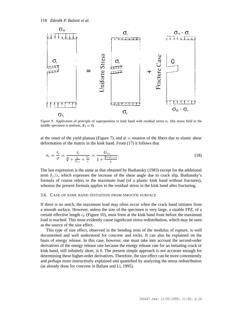
The foregoing analysis is generally valid for any type of distributed or concentrated loadapplied on the top and bottom boundaries of the specimen, provided they are sufficientlyremote. For the special case of a uniform load, the results can be more directly obtained by asimpler procedure that is based on the principle of superposition. As illustrated in Figure 9,the solution for a specimen with residual stress in the kink band consists of the solution of aspecimen in which the distributed load at the top and bottom boundaries is equal to the residualstress (in which case the stress state is uniform,σ = σr) plus the solution of a specimen with amode I stress-free crack loaded at top and bottom boundaries byσN−σr. In that case it sufficesto take theJ -integral only along the pathBCDEFG, that is, omit the segmentsAB andHGalong the crack surface. In such an approach, (5) vanishes. This leads directly to an expressionof the type (14), but withσN − σr on the left-hand side, which is evidently equivalent to (12).
In a complete analysis of the boundary value problem, the values ofδc and of the kinkband length are determined by the condition that the total stress intensity factor caused by theapplied load and by the band-bridging stresses must vanish. As shown by Palmer and Rice(1973), by writing this conditions for the limiting case of an infinite body, an estimate of thelength of the FPZ of the kink band can be obtained from the slope of the stress-displacementlaw of the cohesive shear cracks and their spacings. From that length and the spacing, viceversa, one can obtain an estimate of the slope of the stress-displacement diagram.
Instead of expanding into Taylor series functiong(α), it is equally justified to expand apower ofg(α) as a function of a power ofα. In this way (same as in Bažant 1997 or Bažantand Planas 1998, Eq. 9.1.34), one can show that (12) may be replaced by the following moregeneral formula (Figure 8(a,b)):
σN = σR + σ0
[1+
(D
D0
)r]−1/2r
. (16)
Exponentr, a constant, controls the curvature of the size effect plot in Figure 8 (left). Theoptimal value ofr needs to be determined either experimentally or by some more refinedtheory (for concrete it is close to 1).
206427.tex; 11/05/1999; 11:04; p.14

Size effect on compression strength of fiber composites failing by kink band propagation117
Figure 8. (a) Size effect law (solid curve) for specimens with a long kink band or notch (Eq.14) and asymptoticformulas (dashed curves). (b) Same but withσN instead of logσN as the ordinate). (c) Size effect law whenPmaxoccurs at kink band initiation.
3.5. RESIDUAL STRENGTH OF SPECIMENS WITH NOTCH OR LONG KINK BAND
The residual stress in the kink band may be estimated by a simple extension of the formulapresented by Budiansky (1983). From the moment equilibrium condition of an element of thekink band between two adjacent shear cracks (shaded, in Figure 6), we have(σ s)(w sinϑ) =(τw)s, which expresses the second-order nonlinear geometric effect of buckling. Assum-ing the fiber inclinationθ at the onset of the slip plateau to be small, we thus have theapproximationsσ = τ/ϑ andσr = τr/ϑ .
The total rotation of the fibers in the kink band may be expressed as
ϑ = ϕ + ϕ + δs= ϕ + τr
Gxy
+ δfs, (17)
in which φ = initial inclination angle of the fibers (an imperfection),Gxy = elastic shearmodulus for planes parallel to the fibers,δf = slip displacement of the axial (shear) cracks
206427.tex; 11/05/1999; 11:04; p.15
118 Zdenek P. Bažant et al.
Figure 9. Application of principle of superposition to kink band with residual stressσr (the stress field in themiddle specimen is uniform,KI = 0).
at the onset of the yield plateau (Figure 7), andφ = rotation of the fibers due to elastic sheardeformation of the matrix in the kink band. From (17) it follows that
σr = τr
ϑ= τr
ϕ + τrGxy+ δf
s
= Gxy
1+ ϕ+(δf /s)ϕ
. (18)
The last expression is the same as that obtained by Budiansky (1983) except for the additionalterm δf /s, which expresses the increase of the shear angle due to crack slip. Budiansky’sformula of course refers to the maximum load (of a plastic kink band without fractures),whereas the present formula applies to the residual stress in the kink band after fracturing.
3.6. CASE OF KINK BAND INITIATION FROM SMOOTH SURFACE
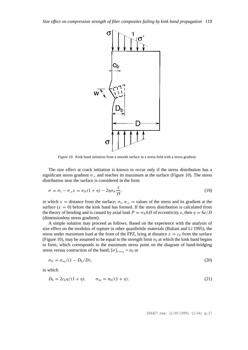
If there is no notch, the maximum load may often occur when the crack band initiates froma smooth surface. However, unless the size of the specimen is very large, a sizable FPZ, of acertain effective lengthcb (Figure 10), must form at the kink band front before the maximumload is reached. This must evidently cause significant stress redistribution, which may be seenas the source of the size effect.
This type of size effect, observed in the bending tests of the modulus of rupture, is welldocumented and well understood for concrete and rocks. It can also be explained on thebasis of energy release. In this case, however, one must take into account the second-orderderivatives of the energy release rate because the energy release rate for an initiating crack orkink band, still infinitely short, is 0. The present simple approach is not accurate enough fordetermining these higher-order derivatives. Therefore, the size effect can be more convenientlyand perhaps more instructively explained and quantified by analyzing the stress redistribution(as already done for concrete in Bažant and Li, 1995).
206427.tex; 11/05/1999; 11:04; p.16
Size effect on compression strength of fiber composites failing by kink band propagation119
Figure 10. Kink band initiation from a smooth surface in a stress field with a stress gradient.
The size effect at crack initiation is known to occur only if the stress distribution has asignificant stress gradientσ,x and reaches its maximum at the surface (Figure 10). The stressdistribution near the surface is considered in the form
σ = σ1− σ,xx = σN(1+ η)− 2ησNx
D, (19)
in which x = distance from the surface;σ1, σ,x = values of the stress and its gradient at thesurface (x = 0) before the kink band has formed. If the stress distribution is calculated fromthe theory of bending and is caused by axial loadP = σNbD of eccentricitye, thenη = 6e/D(dimensionless stress gradient).
A simple solution may proceed as follows. Based on the experience with the analysis ofsize effect on the modulus of rupture in other quasibrittle materials (Bažant and Li 1995), thestress under maximum load at the front of the FPZ, lying at distancex = cb from the surface(Figure 10), may be assumed to be equal to the strength limitσ0 at which the kink band beginsto form, which corresponds to the maximum stress point on the diagram of band-bridgingstress versus contraction of the band;[σ ]x=cb = σ0 or
σN = σ∞/(1−Db/D), (20)
in which
Db = 2cbη/(1+ η), σ∞ = σ0/(1+ η). (21)
206427.tex; 11/05/1999; 11:04; p.17

120 Zdenek P. Bažant et al.
Equation (20) cannot be applied forD 6 Db. But it so happens that the large-size ap-proximation(1 − Db/D)
−1 ≈ 1 + Db/D produces a formula that has the same large-sizeasymptotic behavior yet its behavior is also acceptable for the entire range ofD
σN = σ∞(
1+ Db
D
), (22)
(Figure 8(c)). The values ofσ∞ andDb are constants, the latter representing the thicknessof the boundary layer in which the kink band damage takes place. For a vanishing stressgradient or a vanishing load eccentricity, one hasη = 0, and the (deterministic) size effectthen disappears.
Equation (22) is of the same form as previously derived for concrete (Bažant and Li, 1995,Bažant and Planas, 1997). One can also obtain the same equation by a more sophisticatedanalysis in which the stress redistribution due to the kink band is actually calculated and themaximum load is determined from the redistributed stresses (similar to Bažant and Li, 1995).Such an analysis could also be applied here, but it is more complicated. A still more rationalapproach is an asymptotic analysis based on the energy release functions of LEFM, which isoutlined next.
Equation (22) is accurate only up to the first two terms of the asymptotic power seriesexpansion ofσN in 1/D. This means that other formulae whose asymptotic expansion in 1/D
coincides up to the first two terms with that of (22) are equally justified; for example
σN = σ∞√
1+ 2Db
Dor σN = σ∞
(1+ qDb
D
)1/q
, (23)
with any positive constantq.
4. LEFM of orthotropic materials
For an orthotropic material, the stress intensity factor of a sharp crack with a negligibly smallFPZ may always be written in the form
KI = σN√πDα F(α) (α = a/D), (24)
whereσN = nominal stress, considered here at maximum load,D = characteristic dimension,a = crack length,α = relative crack length, andF(α) = function characterizing structuregeometry and material orthotropy.
The energy release rateG may be related toKI using Bao et al.’s (1992) generalization ofIrwin’s (1958) relation for orthotropic materials
G = K2I
E= D
Eσ 2Ng(α), g(α) = πα[F(α)]2, (25)
whereg(α) = dimensionless energy release function, characterizing the structure geometryand material orthotropy, and
E = 1
Y (ρ)2
(E2/E1)1/4
√(1+ ρ)/2E1E2
, with ρ =√E1E2
2G12−√ν12ν21, (26)
Y (ρ) = [1+ 0.1(ρ − 1)− 0.015(ρ − 1)2 + 0.002(ρ − 1)3][(ρ + 1)/2]−1/4. (27)
206427.tex; 11/05/1999; 11:04; p.18
Size effect on compression strength of fiber composites failing by kink band propagation121
Subscripts 1 and 2 refer to Cartesian axesx1 ≡ x andx2 ≡ y; x2 coincides with the fiberdirection;E1, E2,G12, andν12 are the orthotropic elastic constants; and parametersE2/E1
andρ characterize the degree of orthotropy. The formula is valid when the crack propagatesin the directionx1 orthogonal to the fibers, but it is used here as an approximation even forpropagation directions forming a small angle withx1.
For fracture specimens in the form of long notched strip or slender notched beams, functiong(α) or F(α)may be taken approximately the same as for isotropic specimens.
5. Asymptotic size and shape effect laws via equivalent LEFM
5.1. CASE OF LONG KINK BAND OR LONG NOTCH
Following a procedure analogous to Bažant (1997), we will now try to express the coefficientsof the size effect law (12) in terms of the energy release functions of LEFM. This will furtherallow us to capture the effect of structure geometry (shape). Assuming that the FPZ at thekink band front is not so large as to spoil linearity, the stress intensity factorKI at the tip ofa Mode I crack equivalent to the kink band may be expressed according to the principle ofsuperposition as follows
KI = KPI −Kr
I , (28)
in which
KPI = σN
√Dg(α), Kr
I = σr√Dγ (α) (α = a/D). (29)
Herea is the length of the equivalent LEFM crack, whose tip is expected to lie roughly in themiddle of the FPZ;KP
I orKrI are the LEFM stress intensity factors caused by loadP acting
alone (whereP can represent not only one applied load but also the parameter of a system ofloads), or by a uniform normal tractionσ = σr applied on the crack faces (but not the notchfaces; Figure 5(a));g(α) andγ (α) are dimensionless LEFM energy release functions of theorthotropic specimen.
When the kink band is propagating,G = Gb = fracture energy of the kink band. Itsmeaning, when a residual stress is present, is
Gb = Jcr− σrδr =∫δ
σdδr − σrδr =∫δ
(σ − σr)dδr (30)
Thus, in view of (25) and (28) with (29), we haveKPI − Kr
I = σN√Dg(α)− σr√Dγ (α) =√
EGb (= KIb = stress intensity factor of kink band). From this,
σN =√EGb + σr√Dγ (α)√
Dg(α). (31)
This formula, however, is not acceptable for small sizes of notched specimens; it yieldsσN →∞ for D→ 0 because limg(α) = g(α0) > 0.
If there is no notch,a0 represents the length of the portion of the kink band length alongwhich the normal stressσ transmitted across the band has already been reduced to the residual
206427.tex; 11/05/1999; 11:04; p.19

122 Zdenek P. Bažant et al.
valueσr . This is the distance from the notch mouth or from the beginning of the kink band tothe beginning of the FPZ (Figure 5(a)).
By cutting geometrically similar notches of deptha0 in specimens of suitable geometrywith a suitable type of loading, one can achieve that the FPZ at maximum load be still attachedto the notch tip. In that case,α0 = a0/D = constant for all the specimen sizesD, which isconvenient for evaluating test data.
A basic question is what is the value ofa − a0 at the maximum load,Pmax. In view ofextensive experimental evidence and finite element results for other quasibrittle materials(Bažant and Planas 1998), it is reasonable to introduce the following simplifying hypothesis:The effective lengthcb = a−a0 of the FPZ of the kink band atPmax (Figure5) is approximatelyconstant, governed essentially by the microstructure.
5.1.1. Large-size asymptoticsTo deduce the large-size asymptotic behavior, we writeg(α) = g(α0+θ) andγ (α) = γ (α0+θ) where
θ = cb/D, α = α0+ θ (32)
and expand functionsg andγ into a Taylor series as powers ofθ , centered at pointα0 (orD →∞). Then we truncate each series after the second (linear) term. So, we may introduceinto (31) the large-size approximations
g(α) ≈ g0+ g′θ, γ (α) ≈ γ0+ γ ′θ, (33)
in which g0 = g(α0), γ0 = γ (α0), and the primes denote the derivatives with respect toα;g′ = dg(α)/dα, γ ′ = dγ (α)/dα at α = α0. With these approximations, one obtains thefollowing size effect law for failures occurring only after a long stable kink band growth(Figure 8(a,b)))
σN =√EGb + σr√γ ′cb + γ0D√
g′cb + g0D, (34)
or, upon further algebraic rearrangement
σN = σ0+ σY√1+D/D1√1+D/D0
, (35)
in which
D0 = cb g′
g0, D1 = cb γ
′
γ0, σ0 =
√EGb
cbg′ , σY = σr
√γ ′
g′. (36)
Formula (35) has the following asymptotic values
for largeD: σN = σY√D0
D1= const.= σr γ0
g0
√g′
γ ′, (37)
for smallD: σN = σ0+ σY = const. (38)
206427.tex; 11/05/1999; 11:04; p.20

Size effect on compression strength of fiber composites failing by kink band propagation123
The size effect curve of log(σN − σY ) versus logD represents a smooth bridging between thesize effect of plasticity (i.e. the case of no size effect, corresponding to a horizontal line) andthe size effect of LEFM (i.e. the case of the strongest possible size effect, corresponding toa straight line of downward slope−1
2). The fact that the small-size asymptote is horizontalagrees with the fact that the strength theory or plasticity ought to be a good approximation forsmall sizes because the failure cannot localize.
SizeD0, called the transitional size, represents the intersection of the power scaling lawsfor plasticity and LEFM and characterizes the transition from plastic to brittle behavior. Theratio
β = D/D0 (39)
is a hypostatic characteristic called the brittleness number of a structure (Bažant and Planas1998). Forβ → 0, the structural behavior is perfectly ductile (plastic), and forβ →∞ withσR = 0, the behavior is perfectly brittle, described by LEFM. Note that the shape effect onstructural brittleness is included through functiong(α) used to calculateD0.
If the FPZ of the kink band is still attached to the tip at maximum load,γ0 = 0 in (33), andso, for any structure geometry, the near-tip asymptotic behavior of functionγ (α) for α → α0
is (see Appendix III)
γ (α) = γ ′θ, with γ ′ = 8/π, γ ′ = γ ′(α − α0). (40)
Thus (33) becomes a one-term linear approximationγ (α) ≈ γ ′θ for D → 0. This mightnot be sufficiently accurate for smallerD. For a broader range of sizes including smallD,one must use at least a two-term approximation,γ (α) ≈ γ ′θ + 1
2γ′′θ2, or even better, not
to replaceγ (α) by an approximation. Thus, for notched specimens, the following formulashould have a broader range of accuracy than (34)
σN =√EGb + σr√Dγ (α)√
g′cb + g0D(FPZ at notch), (41)
although it cannot be used if the structure is so small thatα = α0 + cb/D corresponds to apoint that lies outside the structure or near its surface.
With the one-term linear approximationγ (α) = γ ′θ , (31) and (34) reduce to the classicalsize effect law derived in 1984 for notched Mode-I (tensile) fracture specimens of positivegeometry (i.e., those withg′ > 0)
σN =√
EGB
g′cb + g0D= σ0√
1+D/D0(FPZ at notch), (42)
where
GB = (Kb + σr√γ ′cb )2 / E with Kb =
√EGb, γ ′ = 8/π (43)
HereKb is the fracture toughness of the kink band, andGB must be the same as in (15),representing the total fracture energy including the energy dissipation byσr . The value ofγ ′ isindependent of the structure geometry. Equation (42) is the special case of (35) forD1→∞.
206427.tex; 11/05/1999; 11:04; p.21

124 Zdenek P. Bažant et al.
Since functionsg(α) and γ (α) capture the effect of structure geometry, the foregoingformulae give not only the effect of size but also the effect of shape.
5.1.2. Small-size asymptoticsTo deduce the small-size asymptotic behavior, we introduce new parameterξ = 1/θ = D/cband new LEFM functions
p(α0, ξ ) = ξg(α0+ ξ−1), ω(α0, ξ ) = ξγ (α0+ ξ−1). (44)
Then we substituteg(α) = p(α0, ξ )/ξ and γ (α) = ω(α0, ξ )/ξ into (31), expand thesefunctions into a Taylor series inξ centered at pointξ = 0 (or D → 0), and truncate theseries after the second (linear) term, i.e.
p(α0, ξ ) ≈ p0+ p′ξ, ω(α0, ξ ) ≈ ω0+ ω′ξ, (45)
wherep0, ω0, p′, ω′ = constants. Expressingg andγ from (44) and substituting into (31), we
obtain, after rearrangements,
σN =√EGb + σr√ωcb + ω′D√
pcb + p′D . (46)
This expression can be brought to the form of the large-size asymptotic approximation (36) inwhich
D0 = cb p0
p′, D1 = cb ω0
ω′, σ0 =
√EGb
cbp0, σY = σr
√ω0
p0. (47)
5.1.3. Asymptotic matching characterFor large enough sizes, the original formula (31) is more accurate than its subsequent approx-imations. But this formula is unacceptable forD → 0, giving σN → ∞. This conflicts withthe small-size asymptotic form (46) which gives a finiteσN . On the other hand, the approx-imations (35), (34), (41)and (42) of the large-size asymptotic formula happen to have alsothe correct small-size asymptotic behavior forD → 0, approaching a horizontal asymptote.Moreover, they happen to have the same form as the small-size asymptotic approximation in(46). This means that these approximations serve as an interpolation between the oppositeinfinities (in the logD scale), generally called asymptotic matching.
There is a difference, though. In asymptotic matching, solutions that are accurate for oneand the other infinity serve as the starting point. Here, however, the small-size approximationcannot be accurate in the limit forD → 0 because it is based on LEFM while the FPZ is inthe limit larger than the structure (properly one would need to use for the small-size limit thenonlocal theory of damage localization, which however does not seem amenable to a simpleanalytical solution). So the numerical values ofD0,D1, σ0, σ1 for the small-size approxim-ation cannot be reliably predicted. Therefore, the asymptotic matching with the small-sizeasymptotic approximation (46) can only indicate the form of the matched asymptotic formulabut not its coefficients (in particular, the horizontal asymptoteσ = σ0 could be higher or lowerthan indicated by (47)). For this reason, we simply assumeD0,D1, σ0, σ1 to be the same as
206427.tex; 11/05/1999; 11:04; p.22

Size effect on compression strength of fiber composites failing by kink band propagation125
for the large-size asymptotic, and content ourselves with merely having the correct asymptoticform forD→ 0.
Since the justification of (35) rests in the matching of the asymptotic behaviors at oppositeinfinities, any smooth formula that satisfies the same small-size and large-size asymptoticproperties should be equally valid; for instance,
σN = σ0+ σY [1+ (D/D1)r ]1/2r
[1+ (D/D0)r ]1/2r , (48)
wherer is any positive constant. This formula may be derived similarly as (35) except thatone needs to setζ = θr , g(α) = [g(ζ )]1/r , γ (α) = [γ (ζ )]1/r , and use instead of (33) theapproximationsg(ζ ) = g0 + g′ζ andγ (ζ ) = γ0+ γ ′ζ .
5.1.4. Length of kink band at maximum loadIn the classical LEFM corresponding toσr = 0, specimens of positive geometry, i.e. thosewith g′(α0) > 0, attainPmax while the FPZ is still attached to the notch. Then a sufficientcharacteristic ofPmax is that G = Gb, which implies that the FPZ length 2c has grown toits full value 2cb. If the geometry is negative,g′(α0) < 0, the kink band propagates stably,at increasing loadP , andPmax occurs at kink band lengtha such thatg′(α) = 0. When anR-curve,R(c), is considered, the condition ofPmax is thatG′(a) = R′(c).
These conditions, however, do not apply ifσr > 0. The total energy release rate due toP andσr may be written asG = K2
I /E whereKI = [σNk(α) − σrκ(α)]√D; k(α) =
√g(α)
andκ(α) =√γ (α) (dimensionless stress intensity factors of kink band). Under gravity load,
the kink band is stable ifG′ > 0 or dKI/dα > 0, and it is critical (i.e., the loadP = Pmax) ifdKI/dα = 0. This yields for gravity loading the conditions
k′(α) < κ ′(α)σr/σN........ stable,P growing, (49)
= ........ critical, P = max. (50)
The latter is of course the condition of maximum load for any type of loading (an equivalentequation withoutσN and in terms ofg(α) was derived from the condition dσN/dα = 0 by Zi,1999).
If condition (50) is violated already while FPZ is attached to the notch tip (α0 = αn), Pmax
occurs right at the beginning of kink band propagation, i.e., as soon asG =Gb. Otherwise thevalue ofα0 (location of the beginning of the FPZ atPmax) along withPmax must be found bysolving equations (42) and (50), in whichα = α0+ cb/D (≈ coordinate of FPZ center).
Compared to propagation of cracks without residual stress, the range of stability of propa-gating kink bands is wider. According to (49), it includes not only negative but also positivevaluesg′(α), up to a certain limit proportional toσr . So, a stable kink band growth can occureven for positive geometries (which is the case of the present tests). The previous difficultiesin achieving stable pre-peak growth of a long kink band in experiments must have been dueto unsuitable specimen and loading geometries (in post-peak, a stable growth further requiresa sufficiently stiff loading).
206427.tex; 11/05/1999; 11:04; p.23

126 Zdenek P. Bažant et al.
5.1.5. Other aspectsFormula (12), which was derived for a long rectangular strip, is a special case of the generalformula (35) for the caseD1 = D0, i.e., forγ (α) = g(α). The case of such an equivalenceof the energy release functions means that the corresponding stress intensity factors are equal.This is immediately evident from the decomposition in Figure 10 based on the principle ofsuperposition; indeed, the middle specimen is in a homogeneous stress state and thus has nostress singularity (KI = 0).
Formula (34) is of the same form as the formula derived in general for compression failuresunder the assumption that the laterally propagating damage band causing compression failureapplies a uniform pressure on its boundaries (Bažant and Chen 1997, Eq. 51).
In a similar manner as shown in Bažant (1997) for cracked specimens, the foregoing ana-lysis could be refined by considering that the kink band ought to exhibitR-curve behavior.In other words, the critical energy release may be expected to follow anR-curve, such thatG = Rb(c) whereRb(c) is assumed to be a given function of the kink band extensionc.The only change needed in the preceding formulation is to replace the value
√EGb in (31)
by√ERb(c). In addition to this, it becomes possible to implement in the calculations the
condition of failure as a stability limit, which can be reduced to the condition of tangency ofthe curve of energy release rate at constant load to theR-curve (Bažant 1997) (this conditioncannot be imposed when the critical energy release rate is constant, being equal toGb, asassumed in the preceding).
Similar to (14), Equation (35) is accurate only up to the first two terms of the power seriesexpansion in(1/D). Therefore, it could be generalized in the same manner as (16).
5.2. CASE OF KINK BAND INITIATION FROM SMOOTH SURFACE
For kink bands originating from a smooth surface, one may usually assume thatPmax occursat the beginning of propagation, while the FPZ is still attached to the surface. Accordingly,the initial crack length for the LEFM approximationa0 = 0 orα0 = 0. But the energy releaserate of a crack of zero length vanishes,g(α0) = γ (α0) = 0. Thus, if we truncated the Taylorseries expansion ofg(α0 + θ) andγ (α0 + θ) after the linear term, we could not capture thesize effect. Therefore we need to truncate these series only after the quadratic term. In thismanner, the large-size approximation of (31) takes the form
σN =√EGb + σr
√γ ′cb + γ ′′(c2
b/2D)√g′cb + g′′(c2
b/2D)(FPZ at surface). (51)
This may be rearranged as
σN =√EGb/cb + σr√γ ′(1+ 2χ1)√
g′(1− 2χ0), with χ0 = − g
′′cb4g′D
, χ1 = γ ′′cb4γ ′D
, (52)
with the notationsg′ = dg(α)/dα, γ ′ = dγ (α)/dα, g′′ = d2g(α)/dα2, γ ′′ = d2γ (α)/dα2, allevaluated atα = α0 = 0; χ0 is defined with a minus sign becauseg′′ is negative in bendingspecimens (Bažant and Li 1996).
Equation (52), however, is not acceptable for smallD → 0 because it givesσN → 0.Therefore, it is expedient to transform it by asymptotic approximations that do not change the
206427.tex; 11/05/1999; 11:04; p.24

Size effect on compression strength of fiber composites failing by kink band propagation127
asymptotic behavior forD → ∞ while making at the same time the formula acceptable forD → 0. Such approximations are
√1+ 2χ1 ≈ (1+ qχ1)
1/q and 1/√
1− 2χ0 ≈ (1+rχ0)1/r ,
with any positive constantsr andq. For the caser = q = 1, after noting that(1+χ1)(1+χ0)
≈ 1+ χ0 + χ1 for largeD, we obtain a size effect formula identical to (22) (Figure 8(c)), inwhich
σ∞ =√EGb
g′cb+ σr
√γ ′
g′, (53)
Db = − cb
4σ∞
g′′g′
√EGb
g′cb+ σr
(g′′
g′− γ
′′
γ ′
)√γ ′
g′
. (54)
A generalization in the form of (23) is also possible.With (53), we have thus obtained a more general confirmation of (22). Note that although
the approximations that led from (52) to (53) are only first-order accurate in 1/D, (51) is first-order accurate in 1/D as well. So, these approximations cause no loss in accuracy overall. But(53) can be applied more widely because it has a realistic behavior also forD→ 0 while (52)does not.
5.3. TRANSITION BETWEEN LONG AND SHORT KINK BANDS AND UNIVERSAL SIZE
EFFECT LAW
For smallα0, there must be a continuous transition between the size effect law for specimenswith a notch or long kink band and that for specimens failing at kink band initiation from asmooth surface. A universal size effect law that describes this transition has already been de-veloped for fracture of concrete (σr = 0; Bažant 1997). By a similar matching the asymptoticbehaviors for long and short kink bands, a similar universal size effect law can be developedfor kink bands.
6. Identification of fracture parameters from kink band tests
6.1. FPZAT NOTCH TIP
It is convenient to cut notches in the compression test specimens. The notch ensures the kinkband to start in one place (which eliminates any possible statistical effect due to random spatialvariation of local strength). Furthermore, if a suitable loading is used, it further ensures theFPZ at maximum load to be still attached to the notch tip. This brings about an importantsimplification—the value ofα0 can be controlled and thus is known.
The size effect formula for notched specimens, (14) with (43), can be used for identifyingthe fracture energy of the kink band,Gb, and the FPZ length,cb, from the measurements ofsize effect. The procedure may be based on determiningD0 andσ0 by fitting the formula (42)to maximum load data for notched specimens of sufficiently different sizes; then
cb = D0g0
g′, GB = cb
Eg′σ 2
0 . (55)
If geometrically similar specimens and notches are used,α0 = constant for allD. Geomet-rical similarity is not a requirement because the equivalent LEFM functionsg andγ capture
206427.tex; 11/05/1999; 11:04; p.25

128 Zdenek P. Bažant et al.
the shape effect as well. Geometrical similarity, however, simplifies the evaluation of testresults and improves the accuracy because the shape effect is known only approximately andthus introduces some additional error.
The fitting of (41) or (34) toσN data may be best accomplished the Levenberg–Marquardtnonlinear optimization algorithm. Alternatively, by algebraic rearrangement, equation (42)may be transformed to a linear regression plotY = AD + C for which
Y = 1
σ 2, GB = g0
AE, cb = C
A
g0
g′. (56)
The procedure is identical to that embodied in the RILEM Recommendation for concrete(whose statistical treatment and proper weighting is described in Bažant and Planas, 1998,Sec. 6.3).
According to (43), the kink band fracture energy may then be calculated as
Gb = (
√EGB − σr
√γ ′cb ) / E, (57)
provided thatσr is determined separately.An approximate way to estimateσr may be to measure the residual load on very large
specimens, provided that a post-peak plateau can be reached. Additional damage long afterthe peak load, however, may further reduce the stress in the kink band, making it hard toidentify a plateau. An upper bound onσr is provided by the compression strength of verysmall specimens with nearly uniform stress distribution at peak load.
Another way to determineσr may be to test both notched and unnotched specimens, anduse the Marquardt–Levenberg optimization algorithm to fit the maximum load data by (41)and (51), consideringGb, cb andσr as three unknowns.
Still another way to determineσr might be to measure under uniaxial compression the post-peak behavior of very small unnotched prismatic specimens – so small that the FPZ of the kinkband would occupy the whole cross section, thus ensuring simultaneous (nonpropagating)failure.
It is instructive to relateGB to theJ -integral. Consider theJ -integral path starting at pointC in Figure 11 (top) of the imagined cohesive crack representing the kink band. PointC liesimmediately ahead of the tip of the notch, and so theJ integral along the path starting atC represents the total energy flux into the cohesive crack equivalent to the kink band. Whenthe extension of this crack (or kink band) is sufficient to reduce the stress at pointC to theresidual stressσr , the full fracture energyGb of the kink band comes into play, and then, by asimilar derivation as that which led to (10), theJ -integral along the path starting atC, whichmust be equal toGB , is Jcr = GB , GB = Gb + σrδr (Equation 10) whereδr is the normaldisplacement (contraction) across the kink band at the notch tip (or the end of the FPZ), andGb is the fracture energy representing the cross-hatched triangular area in Figure 7 (bottom).Knowingσr , this relation can be used to estimate the value ofδr .
The value ofδr ought to be equal to the opening displacement of the equivalent LEFMcrack at the location of the notch tip (Figure 11). This displacement may be calculated fromthe parabolic asymptotic profile of the equivalent LEFM crack, whose tip lies at distancecBfrom the notch tip. According to the well-known formula (e.g. Eq. 5.5.11 in Bažant and Planas1998), one may use the approximation
δr =√
32GBcb/πE. (58)
206427.tex; 11/05/1999; 11:04; p.26

Size effect on compression strength of fiber composites failing by kink band propagation129
Figure 11. Equivalent cohesive crack emanating from the notch tip (top), equivalent LEFM crack (bottom), andJ -integral paths.
6.2. FPZREMOTE FROM NOTCH AND SPECIMENS WITH END RESTRAINT
While the rotational restraint at the ends of the present carbon-PEEK specimens has madeit possible to demonstrate a long stable growth of kink band, it has slightly complicated theanalysis of test results. The restraint causes the axial load resultantP to gradually shift to theright in Figure 1(a) as the kink band propagates, i.e., the resultant eccentricitye (Figure 1(a)and 13) increases as a function ofα. Functione = e(α) is determined by the condition thatthe relative rotation between the specimen endsφ = PCPM + MCMM + σrCMr = 0 whereM = Pe = moment of the resultant. Consequently,
e(α) = −[PCPM(α)+ σrCMr(α)]PCMM(α)
(P = σNbD). (59)
The compliances, according to well-known LEFM relations (e.g. Bažant and Planas 1998, Eq.3.5.18), are
CPM(α) = 2
bE
∫ α
0kP (α
′)kM(α′)dα′, CMM(α) = 12L
bD3E+ 2
bE
∫ α
0[kM(α′)]2 dα′,
CMr(α) = 2
bE
∫ α
0kM(α
′)kr(α′)dα′, (60)
whereb,L = specimen thickness and length (Figure 1(a)), and thek’s are the dimensionlessstress intensity factors for unit loading byP,M or σr ; kP = KP
I b√D/P , kM = KM
I bD3/2/M
andkr =KrI /σr√D. Also,
g(α) = σ 2ND{kP (α)+ kM(α)e(α)/D}2. (61)
206427.tex; 11/05/1999; 11:04; p.27

130 Zdenek P. Bažant et al.
According to Tada et al. (1985),kP (α) =√πα(1.122− 0.231α + 10.55α2 − 21.71α3 +
30.38α4), kM(α) =√πα(1.122− 1.40α + 7.33α2− 13.08α3 + 14.0α4). Forkr see Appendix
IV.If σr were 0, then the failure after a long kink band growth, observed in the present carbon-
PEEK tests, would have to be characterized byg′(α) = 0, which would require the use offormulae based approximatingg(α + cb/D) up to the quadratic term incb/D. However,becauseσr is not 0 (nor negligible), the formulae based on approximation up to the linearterm are appropriate.
To identify the values ofGb, cb, α0 andσr from the present carbon-PEEK tests, equation(59) and the expressionα = α0 + cb/D must first be substituted into (42) and (50). Then thestandard library subroutine for the Levenberg–Marquardt nonlinear optimization algorithmmay be used to minimize the sum of the squares of (50) and of the deviations of (42) from thedata points.
To succeed, the tests must cover a sufficient range of brittleness numberβ = D/D0. If therange ofβ is too limited, the fitting problem may be ill-conditioned. Then one needs to dropσr from the set of unknown variables in the least-square fitting, and estimateσr in advance byother means, as already discussed (e.g., from measurements of post-peak behavior), or use indata fitting various estimated fixed values ofσr and then compare the results.
In the present study, however, the values ofe andα0 atPmax have not been calculated bythe aforementioned procedure. Rather, for the sake of simplicity, the values that were alreadyavailable from a finite element simulation with the cohesive crack model carried out earlier byG. Zi have been used in fitting (42) to the data points in Figure 12 (top left). This furnishedthe following material parameters of the carbon-PEEK composite tested
Gb = 27.9 kN/m, cb = 0.70 mm, σr/σ0 = 0.436, σ0 = 758 MPa. (62)
Figure 12 on top right shows also a comparison of the data with the size effect plot based onthe material parameters obtained with the cohesive crack model. The plot is very close to thatin Figure 12 on top left.
It is instructive to compare these values to those obtained by simple fitting of the datawith the size effect law (14) shown in Figure 13. They areσ0 = 779 MPa andcb = 18.5 mm.Althoughσ0 is about the same,cb is far too large, by an order of magnitude. This demonstratesthat the differences ine/D andα0 among specimens of different sizes cannot be neglected.
6.3. TEST SIMULATION BY COHESIVE CRACK MODEL
Simulations of the present and other tests with the cohesive crack model will be reportedseparately (Bažant and Zi, 1999). Two-dimensional elastic finite element analysis has beenapplied to obtain the compliance matrices for forces and displacements at the specimen endsand at the nodal points placed on the sides of the kink band. The condition that the kinkband contraction indicated by the softening stress-displacement law must be compatible withthe elastic deformation of the specimen leads to one integral equation, and the condition thatthe stress intensity factor at the kink band front must vanish leads to another. Based on thenodal point discretization, both integral equations are approximated by a system of algebraicequations, which is then solved by incremental loading.
A computer program for calculating the values ofPmax, e(α) andα0 from any given valuesof Gb, cb andσr has been written. The values ofGb, cb andσr have then been optimized so
206427.tex; 11/05/1999; 11:04; p.28

Size effect on compression strength of fiber composites failing by kink band propagation131
Figure 12. Optimum fits by size effect formulae and by numerical analysis with the cohesive crack model.
as to obtain the best possible fit of the test data. In the process, eccentricitiese have also beendetermined.
The calculated subsequent stress profiles throughout the ligament, along with the corres-ponding eccentricitiese of the load resultant, are shown in Figure 14. The optimum fit ofthe test data by the cohesive crack model, with log(σN − σr) as the ordinate, is shown bythe curve in Figure 12 (bottom). The corresponding optimum value of fracture energy isGb = 28.2 kN/m, which is almost the same as in (62), but the length of the softening segment(Figure 14), which is about 2.7 mm for allD, is almost twice as large as 2cb. This suggeststhat the tip of the equivalent LEFM crack might not be at the center of the FPZ but fartherbehind its front. The optimum fit, however, is not very sensitive tocb; this is documented byFigure 12 (top left and right), with logσN as the ordinate, which shows the optimum fit by thecohesive crack model (solid curve) and the results from (42) based on the optimum materialparameters obtained with the cohesive crack model. Note that the dashed curves in Figure 12on top left and right, corresponding to rather differentcb, are not very different. To eliminatethis ambiguity, tests of a broader size range or fitting of post-peak response would be needed.
206427.tex; 11/05/1999; 11:04; p.29

132 Zdenek P. Bažant et al.
Figure 13. Stress profiles across the ligament of the carbon-PEEK specimens before, at and after the maximumload (note the shift of the compression resultantP which makes a stable kink band growth possible).
Figure 14. Constant-size carbon-epoxy specimen with holes of various diameters used by Soutis, Curtis and Fleck(1993).
7. Soutis et al.’s tests of carbon-epoxy laminates with holes of various sizes
The studies of kink band failures of composites have so far not been focused on the size effect.No data for geometrically similar specimens seem to be available in the literature. However,since functionsg(α) andγ (α) characterize the shape effect, test data on nonsimilar specimensexhibiting the effect of shape can also be used to check and calibrate the theory provided thatthe range of the brittleness numberβ = D/D0 in (12) is sufficient. The recent test data of
206427.tex; 11/05/1999; 11:04; p.30

Size effect on compression strength of fiber composites failing by kink band propagation133
Figure 15. Soutis, Curtis and Fleck’s (1993) test results for quasi-isotropic and orthotropic carbon–epoxy lam-inates of six different layups, with holes of various radiiR (data points) and constant widthD. Solid curves:optimum fits by size-shape effect law in (31). Dashed curves: predictions of strength theory exhibiting no sizeeffect.
206427.tex; 11/05/1999; 11:04; p.31

134 Zdenek P. Bažant et al.
Figure 16. Dimensionless energy release functiong(α) for isotropic specimens with centric holes of differentradii (derived by Führing, 1973).
Soutis and Fleck (1991), Soutis, Fleck and Smith (1991), and Soutis, Curtis and Fleck (1993)exhibit a broad enough range of brittleness numbers, attained not through a variation of theoverall specimen sizeD (which was kept constant) but through a variation ofD0.
Soutis et al. (1991) used rectangular panels of constant widthD to study how centricholes of various radiiR affect the compressive strength of unidirectional and multidirectionalcarbon/epoxy (T800/924C) laminates of different layups, labeled as L1 to L6 (Figure 14 left).The specimens were 50 mm wide, 245 mm long and 3 mm thick, and the diameter–widthratio 2R/D varied from 0.08 to 0.60 for each layup. The results, shown by the data pointsin Figure 15, offer another possibility to check the present theory for a different geometry anda different material, and to compare it to the classical strength theory.
The layups of laminates of Soutis et al. were either quasi-isotropic of only weakly ortho-tropic. Thus the corrections for orthotropy are either unnecessary or almost unimportant forthese tests. In view of the fact that, for long cracked strips without holes, the same dimension-less energy release functions can be used as for isotropic specimens (Bao et al. 1992), it isassumed that the same can be done for specimens with holes, at least as an approximation.
Therefore, the effect of the mild orthotropy of some of the Soutis et al.’s laminate layupsis taken into account only throughE. With this assumption, the analysis of these data is madeeasy by the availability of the solution of the stress intensity factorKI (Führing 1973, andMurakami’s 1987 handbook, p. 291) for an in finite strip with a hole, which may be used asan approximation for a rectangular specimen with a hole (Figure 14). This solution, used herefor compressive instead of tensile loading, is shown in Figure 16 whereα = (c + R)/D. Asseen, the curve ofKI as a function ofα first quickly rises as the horizontal cracks grow from
206427.tex; 11/05/1999; 11:04; p.32

Size effect on compression strength of fiber composites failing by kink band propagation135
the sides of the hole (Figure 14 left and Figure 16 insert). But soon the slope diminishes asthis curve approximately joins the solid curve in Figure 16, which corresponds toKI(α) for aspecimen containing a centric horizontal crack (of relative depthα) instead of a hole.
By virtue of similarity transformations, the slope of the initial rise of the curve must bethe same as for a crack starting from the surface of an elastic halfspace. For such a crack,KI = 1.12σ
√πc, which implies thatg(α) = K2
I /σ2D = 1.122πc/D andg′(α) = 1.122π <
∞. The formula plotted in Figure 16, however, gives an infinite (vertical) initial slope, whichmeans that its initial portion cannot be accurate. Because of this asymptotic inaccuracy,g′ (atc = 0) in (51) for cracks initiating from a smooth surface is obtained, incorrectly, as infinite,which precludes using this equation and forces us to use the original equation (31) from which(51) was derived. Nevertheless we assume that for the present finite values ofc the formulaplotted in Figure 16 is accurate enough.
The maximum load may be expected to be reached only after the slope of the curve inFigure 16 diminishes and the solid curve is approached, which means that the specimenbehaves roughly as a panel with a large centric crack of length 2(R + c). This is anotherreason why the general original formula (31), rather than formula (51) derived from it for akink band initiating from a smooth surface, appears to be appropriate.
Let us now assume the FPZ of the kink band at maximum load is still attached to the hole.In that case, the equivalent LEFM crack should have its tip roughly at the distancec = cb fromthe hole. This value ofc is large enough for approaching the solid curve in Figure 16, i.e.,a
lies in Figure 16 beyond the sharp decrease of slope of the curves. But then the truncationof the series expansion after the second term that was made in deriving (12) would not beaccurate enough. Therefore, the original formula (31) is used.
In (31), we now haveα = 2(R + c)/D ≈ 2(R + cb)/D. Functionsg(α) andγ (α) arethe dimensionless energy release functions corresponding to the case of a tensioned crackedplate with a centric hole and a pair of cracks, loaded either at the specimen ends or along aportion of each crack (Figure 14 right); see the Appendix. The value of the residual stressσrneeds to be considered as 0 because the FPZ of the kink band is still attached to the hole whenthe maximum load is reached. ConsideringGb andcb as unknowns, Equation (31) has beenfit to the data of Soutis et al. (1993) using the Levenberg-Marquardt nonlinear optimizationalgorithm. The results, shown by the solid curves in Figure 15, are quite satisfactory. Theoptimum values ofGb andcb corresponding to these fits are indicated in each plot in Figure 15(andσr = 0).
To check whether a theory capable of representing the size effect is necessary, the testresults are further compared to the simplest version of a theory that exhibits no size effect– the strength theory in which it is assumed that the specimen fails as soon as the verticalnormal stress at the sides of the hole reaches the strength of the material. The dashed curvesin Figure 15 show the predictions of the strength theory (obtained under the assumption thatthe material strength is the same as used in the kink band analysis). Obviously the trend ofthose curves does not agree with the trend of the data. These comparisons provide additionalsupport for the present theory. They reveal that a theory exhibiting the size effect is necessaryto describe Soutis et al.’s test results well.
The reason that the last data points on the right of the plots for specimens L1, L3 and L4 inFigure 15 systematically deviate slightly upwards from the solid curves for the present theorycould be that (31) is not acceptable for large holes (because the cracks at maximum load arenot long enough for approaching the solid curve in Figure 16).
206427.tex; 11/05/1999; 11:04; p.33

136 Zdenek P. Bažant et al.
8. Conclusions(1) Transverse slanting of the notch in test specimens of carbon-PEEK laminate can achieve
pure out-of-plane kink band failure, not contaminated by shear splitting cracks.(2) Restraining specimen ends against rotation helps to stabilize kink band growth and
makes it possible to demonstrate the possibility of a stable growth of long kink bands beforethe peak load.
(3) Compression tests of notched carbon-PEEK specimens show that the nominal strengthof geometrically similar notched specimens failing purely by kink band propagation exhibitsa strong (non-statistical) size effect.
(4) The size effect observed is transitional between the asymptotic case of no size effect,which is characteristic of plasticity or any theory whose failure criterion is expressed solelyin terms of stress or strain, and the asymptotic case of size effect of linear elastic fracturemechanics, which is governed by energy release.
(5) The results of the present carbon-PEEK tests roughly agree with the approximategeneral size effect law proposed by Bažant (1983, 1984) and derived recently by asymptoticanalysis of energy release (Bažant 1997).
(6) The present theory gives not only the effect of size but also the effect of shape. Thetheory is found to agree with the recent shape effect tests of Soutis et al. (1993), which utilizedconstant-size carbon epoxy specimens with centric holes of different diameters.
(7) The nominal strength of specimens failing at the initiation of a kink band from a smoothsurface is also predicted to exhibit a size effect. A simple size effect formula is derived forthis case, too. This formula is the same as that previously derived for the size effect on themodulus of rupture measured in bending tests of notch-free specimens.
(8) In addition to previous derivations, the size effect law for specimens with notch of longkink band can also be derived by J-integral analysis of energy release, as well as from therecently proposed nonlocal LEFM.
(9) The size effect law for notched specimens permits the fracture energy of the kink bandand the length of the fracture process zone at the front of the band to be easily identified solelyfrom the measurements of maximum loads.
(10) The results suggest that the current design practice, in which the compression failureis predicted on the basis of strength criteria (or plasticity), thus inevitably missing the sizeeffect, is acceptable only for small specimens or structural parts. In the interest of safety, itshould be revised for large structural parts.
Remark on statistical size effect.According to the arguments in Bažant and Planas (1991,ch. 12), this size effect, not addressed here, is overpowered by the present energetic size effect.It is significant only for
(1) very small notched specimens for which the FPZ involves most of the cross section;(2) unnotched specimens so large that the energetic size effect approaches its horizontal
asymptote (Figure 8(c)), and(3) uniformly stressed specimens with negligible FPZ reaching peak load at fracture inititi-
ation (probably relevant to Kyriakides and Ruff, 1997).
206427.tex; 11/05/1999; 11:04; p.34

Size effect on compression strength of fiber composites failing by kink band propagation137
Appendices
I. KI FOR ISOTROPIC PANEL WITH HOLE AND CRACKS
The stress intensity factor for an isotropic panel with a circular hole and two cracks (Figure 14and 16) may be written asKI = σ
√Dk(α) (e.g. Bažant and Planas, 1998, Sec. 5.1) where
k(α) = function of α. Theng(α) = k2(α). The solution ofKI for a cracked rectangularpanel with a centric hole (Figure 14 and 16 insert) was obtained by Führing (1973) (see alsoMurakami, 1987, p. 291). With the notationsα = a/D, α = πα, δ = b/R, γ = 2R/D,β = (2α − γ )(1− γ ), one getsg(α) = 2παF 2(α) whereF(α) = φψ and
φ = 1
π − 1
{π
√1
αtanα + g sin(2α)
(1+ ε
2(2− ε2)
1− ε)+√1+ 2g
}, (63)
ψ = ξ(3β2P/3− 2βP
√ξ). (64)
Hereg = 0.13[(2/π)arctanδ
]2, ε = (α/π)arctan(0.6 3
√δ), P = log(ξ−3/2)/ log(β∗), β∗ =
γ δ/[γ (2δ − 1)+ 1] andξ = 1+ (2/π)arctan(1.5√δ).
II. KI FOR ISOTROPIC PANEL WITH A HOLE LOADED ON A PORTION OF CRACK LENGTH
The stress intensity factor for an isotropic panel in which the crack lips are subjected to adistributed load of resultantP in each crack was calculated by Newman (1982). With thenotationsR = radius of the hole,a = crack length,α = a/D, λ = R/a, β1 = b1/a, β2 = b2/a,b1 orb2= distance between the initial or terminal points of the loaded crack segment (Figure 14right), respectively,
γ (α) = (8/π)α(arcsinβ2− arcsinβ1)F3F4, (65)
where
F3 = G(β, λ)
arcsinβ2− arcsinβ1, F4 = arcsinB2− arcsinB1
arcsinβ2− arcsinβ1
√secπα, (66)
G(β, λ) =[(
1+ A1
1− λ +3A2
2(1− λ)2)
arcsinβ
+(A1
1− λ +(4− β)A2
2(1− λ)2)√
1− β2
]β2
β1
, (67)
with A1 = −0.02λ2+0.558λ4 andA2 = 0.221λ2+0.046λ4, andB1 = sin(πb1/D) / sinπα,B2 = sin(πb2/D) / sinπα.
III. PROOF OF EQUATION(40)
Equation (40) is proven by noting that the stress intensity factorKI caused byσr whenc =cb � a0 is the same as for a crack of length 2a in an infinite body, loaded on the crack faces
206427.tex; 11/05/1999; 11:04; p.35
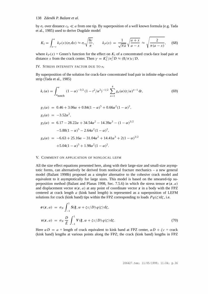
138 Zdenek P. Bažant et al.
by σr over distancecb � a from one tip. By superposition of a well known formula (e.g. Tadaet al., 1985) used to derive Dugdale model
KI =∫ a
a−ckP (x)(σrdx) ≈ σr
√8c
π, kP (x) = 1√
πa
√a + xa − x ≈
√2
π(a − x) , (68)
wherekP (x) = Green’s function for the effect onKI of a concentrated crack-face load pair atdistancex from the crack center. Thenγ = K2
I /σ2r D ≈ (8/π)c/D.
IV. STRESS INTENSITY FACTOR DUE TOσr
By superposition of the solution for crack-face concentrated load pair in infinite edge-crackedstrip (Tada et al., 1985)
kr(α) =∫ α
αnotch
(1− α)−3/2 (1− t2/α2)−1/24∑n=1
gn(α)(t/α)n−1 dt, (69)
g1(α) = 0.46+ 3.06α + 0.84(1− α)5+ 0.66α2(1− α)2,g2(α) = −3.52α2,
g3(α) = 6.17− 28.22α + 34.54α2 − 14.39α3 − (1− α)3/2
−5.88(1− α)5− 2.64α2(1− α)2,g4(α) = −6.63+ 25.16α − 31.04α2 + 14.41α3 + 2(1− α)3/2
+5.04(1− α)5+ 1.98α2(1− α)2.
V. COMMENT ON APPLICATION OF NONLOCAL LEFM
All the size effect equations presented here, along with their large-size and small-size asymp-totic forms, can alternatively be derived from nonlocal fracture mechanics – a new generalmodel (Bažant 1998b) proposed as a simpler alternative to the cohesive crack model andequivalent to it asymptotically for large sizes. This model is based on the smeared-tip su-perposition method (Bažant and Planas 1998, Sec. 7.5.6) in which the stress tensorσ (x, a)
and displacement vectorv(x, a) at any point of coordinate vectorx in a body with the FPZcentered at crack lengtha (kink band length) is represented as a superposition of LEFMsolutions for crack (kink band) tips within the FPZ corresponding to loadsPq(ζ )dζ , i.e.
σ (x, a) = σN
∫ 1
−1S(ξ , α + ζc/D) q(ζ )dζ,
v(x, a) = σND
E
∫ 1
−1V (ξ , α + ζc/D) q(ζ )dζ. (70)
HereαD = a = length of crack equivalent to kink band at FPZ center,αD + ζc = crack(kink band) lengths at various points along the FPZ; the crack (kink band) lengths in FPZ
206427.tex; 11/05/1999; 11:04; p.36

Size effect on compression strength of fiber composites failing by kink band propagation139
occupy the interval(a − c, a + c) corresponding toζ ∈ (−1,1); q(ζ ) = dimensionless loaddistribution function such that
∫ 1−1 q(ζ )dζ = 1. The dimensionless functionsS(ξ , α′) and
V (x, α′) represent the stress tensor and displacement vector at relative coordinate vectorξ =x/D in a body with crack (kink band) lengtha′ = α′D, calculated by LEFM forσN = 1 (orfor loadP = bD). The half-length,c, of FPZ is taken as the smaller ofcb and the distancefrom FPZ center to the notch tip or the surface of the body. In the smeared-tip method, thestresses and displacements on the crack line expressed from (70) are substituted into the stress-separation function of the cohesive crack model, which yields a singular integral equation forq(ζ ). To solve the size effect from that equation is not easy. Therefore it was proposed toavoid prescribing a functional relation between the crack-bridging stress and the crack opening(separation), and introduce instead thehypothesisthat the FPZ propagation is decided by theaverage ofg(α) over the FPZ, i.e., by the condition
σ 2N
ED g(α) = Gb, with g(α) =
∫ 1
−1g(α + ζc/D) q(ζ )dζ. (71)
Acknowledgment
Grateful acknowledgment is due to the Office of Naval Research (monitor Yapa D.S. Ra-japakse) for partial financial support under grants N00014-91-J-1109 (directed by Bažant)N00014-96-1-1219 (directed by Daniel) to Northwestern University. J.-J.H. Kim, E. Becq-Giraudon and M. Brocca wish to thank ONR for financial support under the former grant.
References
Argon, A.S. (1972). Fracture of composites.Treatise of Materials Science and Technology, vol. 1, p. 79, AcademicPress, New York.
Bao, G., Ho, S., Suo, Z. and Fan, B. (1992). The role of material orthotropy in fracture specimens for composites.International Journal of Solid Structures, 29(9), 1105–1116.
Bažant, Z.P. (1976). Instability, ductility, and size effect in strain-softening concrete.Journal of EngineeringMechanics Division, Am. Soc. Civil Engrs.,102, EM2, 331–344; disc.103, 357–358, 775–777,104, 501–502.
Bažant, Z.P. (1983). Fracture in concrete and reinforced concrete, Preprints, IUTAM Prager Symposium onMech-anics of Geomaterials: Rocks, Concretes, Soils, (Edited by Z.P. Bažant), Northwestern University, Evanston,Illinois, 281–316.
Bažant, Z.P. (1984). Size effect in blunt fracture: Concrete, rock, metal.Journal of Engineering Mechanics, ASCE,110, 518–535.
Bažant, Z.P. (1987). Fracture energy of heterogeneous material and similitude. Preprints,SEM-RILEM Interna-tional Conference on Fracture of Concrete and Rock(held in Houston, Texas, June 1987), (Edited by S.P. Shahand S.E. Swartz), publ. by SEM (Soc. for Exper. Mech.) 390–402.
Bažant, Z.P. (1997). Scaling of quasibrittle fracture: Asymptotic analysis.International Journal of Fracture83(1),19–40.
Bažant, Z.P. (1998a). Modeling of compressive strain-softening, fracture and size effect in concrete. vol. 1 (Pro-ceedings of the EURO-C 1998 Conference on Composite Modelling of Concrete Structuresheld at Badgastein,Austria, March 31–April 3, 1998), (Edited by R. de Borst, N. Bicanic, H. Mang, G. Meschke) publ. by A.A.Balkema Publishers, Rotterdam, Netherlands, 249–264.
Bažant, Z.P. (1998b).Nonlocal Fracture Mechanics – Proposal of a new Approach to Nonlinear or QuasibrittleFracture. Preliminary Internal Report, Northwestern University, Dec.
Bažant, Z.P., and Cedolin, L. (1991).Stability of Structures: Elastic, Inelastic, Fracture and Damage Theories,Oxford University Press, New York.
206427.tex; 11/05/1999; 11:04; p.37

140 Zdenek P. Bažant et al.
Bažant, Z.P., and Chen, E.-P. (1997). Scaling of structural failure.Applied Mechanics Reviews ASME50(10),593–627.
Bažant, Z.P., and Kazemi, M. T. (1990). Determination of fracture energy, process zone length and brittlenessnumber from size effect, with application to rock and concrete.International Journal of Fracture, 44, 111–131.
Bažant, Z.P., and Li, Z. (1995). Modulus of rupture: size effect due to fracture initiation in boundary layer.Journalof Structural Engineering ASCE121(4), 739–746.
Bažant, Z.P., and Li, Yuan-Neng (1995). Stability of cohesive crack model: Part II – Eigenvalue analysis of sizeeffect on strength and ductility of structures. Trans. ASME,Journal of Applied Mechanics62(Dec.), 965–969.
Bažant, Z.P., Daniel, I.M., and Li, Zhengzhi (1996). Size effect and fracture characteristics of composite laminates.ASME Journal of Engineering.Materials and Technology118(3), 317–324.
Bažant, Z.P., and Zi, G. (1999).Cohesive Crack Analysis of Kink Band Propagation and Size Effect in FiberComposites. Report, Dept. of Civil Engrg., Northwestern University, Evanston, Illinois – in preparation.
Budiansky, B. (1983). Micromechanics.Computers and Structures16(1–4), 3–12.Budiansky, B. and Fleck, N.A. (1993). Compressive failure of fiber composites.Journal of Mechanics and Physics
of Solids41(1), 183–211.Budiansky, B., Fleck, N.A., and Amazigo, J.C. (1997). On kink-band propagation in fiber composites.Journal of
Mechanics and Physics of Solids46(9), 1637–1635.Christensen, R.M. and DeTeresa, S.J. (1997). The kink band mechanism for compressive failure of fiber composite
materials.Journal of Applied Mechanics ASME64 (March), 1–6.Daniel, I.M., and Hsiao, H.M. (1996). Failure mechanisms in thick composites under compressive loading.
Composites, Part B, 27B 543–552.Dempsey, J.P., Adamson, R.M., and Mulmule, S.V. (1995), Large-scale in-situ fracture of ice. vol. 1 (Procedings
of 2nd International Conference on Fracture Mechanics of Concrete Structures (FraMCoS-2), held at ETH,Zürich), edited by F.H. Wittmann, Aedificatio Publishers, Freiburg, Germany 575–684.
Dempsey, J.P. et al. (1999).International Journal of Fracture(present Special Issue on Fracture Scaling, editedby Z.P. Bažant and Y.D.S. Rajapakse), in press.
Fleck, N.A. (1997). Compressive failure of fiber composites.Advances in Applied Mechanics33, 43–117.Fleck, N.A., and Jelf, P.M. (1995). Deformation and failure of a carbon fibre composite under combined shear and
transverse loading.Acta Metallurgica Materialia43(8), 3001–3007.Fleck, N.A., and Shu, J.Y. (1995). Microbuckle initiation in fibre composites: a finite element study.Journal of the
Mechanics and Physics of Solids43, 1887–1918.Fleck, N.A., Sivashanker, S., and Sutcliffe, M.P.F. (1996). The propagation of a microbuckle in undirectional and
multidirectional composites.Acta Metallurgica Materialia, submitted.Fleck, N.A., Sivashanker, S., and Sutcliffe., M.P.F. (1997). Compressive failure of composites due to microbuckle
growth.European Journal of Mechanics A / Solids16, 65–82.Fleck, N.A., Sutcliffe, M.P.F., Sivashanker, S., and Xin, X.J. (1996). Compressive R-curve of a carbon fibre-epoxy
matrix composite.Composites, Part B: Engineering27B(6), 531–541.Führing, H. (1973). Approximation functions for K-factors of cracks in notches.International Journal of Fracture
9, 328–331.G.R. Irwin, Fracture, inHandbuch der Physik, vol. VI, (Edited by W. Flügge), Springer Verlag, Berlin (1958)
551–590.Jelf, P.M., and Fleck, N.A. (1992). Compression failure mechanisms in unidirectional composites.Journal of
Composite Materials26(18), 2706–2726.Kyriakides, S., Ascerulatne, R., Perry, E.J., and Liechti, K.M. (1995). On the compressive failure of fiber
reinforced composites.International Journal of Solids and Structures32(6/7), 689–738.Kyriakides, S., and Ruff, A.E. (1997). Aspects of failure and postfailure of fiber composites in compression.
Journal of Composite Materials31(20), 2000–2037.Moran, P.M., Liu, X.H. and Shih, C.F. (1995). Kink band formation and band broadening in fiber composites under
compressive loading.Acta Metallurgical Materialia43(8), 2943–2958.Newman, J.C. (1982). A nonlinear fracture mechanics approach to the growth of small cracks.Proceedings,
AGARD Conference on Behavior of Short Cracks on Airframe Components, France.Palmer, A., and Rice, J.R. (1973). The growth of slip surfaces in the progressive failure of over-consolidated clay.
Proceedings of the Royal Society of LondonA332, 527–548.Rice, J.R. (1968a). A path independent integral and the approximate analysis of strain concentrations by notches
and cracks.Journal of Applied Mechanics ASME35, 379–386.
206427.tex; 11/05/1999; 11:04; p.38

Size effect on compression strength of fiber composites failing by kink band propagation141
Rice, J.R. (1968b). Mathematical analysis in the mechanics of fracture. InFracture – an Advanced Treatise, vol.2, (Edited by H. Liebowitz), Academic Press, New York, 191–308.
Rosen, B.W. (1965). Mechanics of composite strengthening.Fiber Composite Materials, Am. Soc. for MetalsSeminar, Chapter 3, American Society for Metals, Metals Park, Ohio, 37–75.
Schultheisz, C.R. , and Waas, A.M. (1996). Compressive failure of composites, part I: testing and micromechanicaltheories.Progresive Aerospace Science32, 1–42.
Soutis, C. and Fleck, N.A. (1990). Static compression failure of carbon fibre T800/924C composite plate with asingle hole.Journal of Composite Materials24, 536–558.
Soutis, C., Fleck, N.A., and Smith, P.A. (1991). Failure prediction technique for compression loaded carbon fibre-epoxy laminate with open holes.Journal of Composite Materials25 (Nov.), 1476–1497.
Soutis, C., Curtis, P.T., and Fleck, N.A. (1993). Compressive failure of notched fibre composites.Proceedings ofthe Royal Society of London A440, 241–256.
Sutcliffe, M.P.F., and Fleck, N.A. (1994). Microbuckle propagation in carbon fibre-epoxy composites.ActaMetallurgica et Materialia42(7), 2219–2231.
Sutcliffe. M.P.F., Fleck, N.A., and Xin, X.J. (1996). Prediction of compressive toughness for fibre composites.Proceedings of the Royal Society of London, SeriesA452, 2443–2465.
Tada, H., Paris, P.C. and Irwin, G.R. (1985),The Stress Analysis of Cracks Handbook, Del Research Corp.,Hellertown, PA.
Waas, A.M., and Schultheisz, C.R., (1996). Compressive failure of composites, part II: experimental studies.Progressive of Aerospace Science32, 43–78.
Zi, Goangseup (1998). Note privately communicated to Z.P. Bažant on Nov. 13.
206427.tex; 11/05/1999; 11:04; p.39