size dependent ion-exchange of large mixed-metal … accompanied by a ... catalytic activity in...
TRANSCRIPT

PolymerChemistry
PAPER
Cite this: Polym. Chem., 2015, 6,6870
Received 15th May 2015,Accepted 14th August 2015
DOI: 10.1039/c5py00714c
www.rsc.org/polymers
Size dependent ion-exchange of large mixed-metal complexes into Nafion® membranes
Elise M. Naughton, Mingqiang Zhang, Diego Troya, Karen J. Brewer† andRobert B. Moore*
Perfluorosulfonate ionomers have been shown to demonstrate a profound affinity for large cationic
complexes, and the exchange of these ions may be used to provide insight regarding Nafion® mor-
phology by contrasting molecular size with existing morphological models. The trimetallic complex,
[{(bpy)2Ru(dpp)}2RhBr2]5+, is readily absorbed by ion-exchange into Na+-form Nafion® membranes under
ambient conditions. The dimensions of three different isomers of the trimetallic complex were found to
be: 23.6 Å × 13.3 Å × 10.8 Å, 18.9 Å × 18.0 Å × 13.7 Å, and 23.1 Å × 12.0 Å × 11.4 Å, yielding an average
molecular volume of 1.2 × 10³ Å3. At equilibrium, the partition coefficient for the ion-exchange of the tri-
metallic complex into Nafion® from a DMF solution was found to be 5.7 × 10³. Furthermore, the total cat-
ionic charge of the exchanged trimetallic complexes was found to counterbalance 86 ± 2% of the
anionic SO3− sites in Nafion®. The characteristic dimensions of morphological models for the ionic
domains in Nafion® were found to be comparable to the molecular dimensions of the large mixed-metal
complexes. Surprisingly, SAXS analysis indicated that the complexes absorbed into the ionic domains of
Nafion® without significantly changing the ionomer morphology. Given the profound affinity for absorp-
tion of these large cationic molecules, a more open-channel model for the morphology of perfluorosul-
fonate ionomers is more reasonable, in agreement with recent experimental findings. In contrast to
smaller monometallic complexes, the time dependent uptake of the large trimetallic cations was found to
be biexponential. This behavior is attributed to a fast initial ion-exchange process on the surface of the
membrane, accompanied by a slower transport-limited ion-exchange for exchange sites that are buried
further in the ionomer matrix.
Introduction
Nafion® is a cation-conducting, electrically insulating, per-fluorosulfonated ionomer membrane that has a high affinityfor large, hydrophobic, cationic compounds.1,2 Since manycatalysts and photosensitizers based on transition metals areoften large cationic complexes bearing organic ligands, theinherent affinity of Nafion® for such complexes makes it anideal substrate for the immobilization of these complexes.3–11
For example, ruthenium complexes have been widely used asphotoactive species and catalysts in Nafion® membranes for avariety of applications, including platinum4 and TiO2
11 cata-lyzed H2 production, O2 evolution,5 photocurrent generationin the presence of a semiconductor,7,9 photoinduced methylviologen radical cation formation,8 and sulfide to sulfoxideoxidation using a lead ruthenate pyrochlore catalyst.10 Manga-
nese and iron catalysts have also shown enhanced electro-catalytic activity in Nafion®.3,6 These studies havedemonstrated that the immobilization of photosensitizers inNafion® can enhance photo-induced electron transfer pro-cesses by limiting intermolecular quenching and vibrationalrelaxation of photoexcited molecules.4,7,10–12 Moreover,Nafion® membranes may also prevent the decomposition ofabsorbed catalysts, resulting in enhanced catalytic perform-ance and stability.3,5
Nafion® is a random copolymer consisting of a tetrafluoro-ethylene backbone and sulfonate terminated perfluoro-
Scheme 1 Chemical structure of Nafion®.†Deceased: October 24, 2014.
Department of Chemistry, Macromolecules and Interfaces Institute, Institute for
Critical Technology and Applied Science, Virginia Tech, Blacksburg, VA 24061, USA.
E-mail: [email protected]
6870 | Polym. Chem., 2015, 6, 6870–6879 This journal is © The Royal Society of Chemistry 2015
Ope
n A
cces
s A
rtic
le. P
ublis
hed
on 1
8 A
ugus
t 201
5. D
ownl
oade
d on
17/
03/2
016
04:1
3:26
. T
his
artic
le is
lice
nsed
und
er a
Cre
ativ
e C
omm
ons
Attr
ibut
ion-
Non
Com
mer
cial
3.0
Unp
orte
d L
icen
ce.
View Article OnlineView Journal | View Issue

vinylether side chains (Scheme 1). The ion exchange capacityof Nafion® membranes can be described in terms of the equi-valent weight (EW), defined as the mass of the dry polymer permole of sulfonate groups. For the H+-form of Nafion®, theequivalent weight is related to m as, EW = 100m + 446, and foran 1100 EW membrane, m = 6.6 (on average). Due to thephenomenon of ionic aggregation,2,13,14 Nafion® consists of atleast two distinct morphological regions: a hydrophobic regionencompassing the polytetrafluoroethylene (PTFE) backboneand a hydrophilic region containing the ionic side-chains.The semi-crystalline hydrophobic region of the ionomer pro-vides the mechanical stability of the membrane while thehydrophilic domains contain ionic aggregates that impart themembrane with unique transport properties related to ion con-ductivity and permselectivity.1,2,15 There are numerous modelsfor the ionic domains of Nafion®. These models are basedupon results from small angle X-ray (SAXS) and neutronscattering (SANS), water uptake, water and ion transport,uniaxial strain, and NMR results.2,13,14,16–26
An early model for Nafion® morphology is the cluster-network model proposed by Gierke and coworkers(Fig. 1a).13,14 This model consists of spherical clusters, 4 nmin diameter, interconnected by 1 nm channels. The 1 nmchannels are included in order to account for the continuouspathway for transport between clusters and high permselecti-vity (i.e. preferential transport of cations) observed for Nafion®
membranes. The characteristic dimensions of the 4 nmclusters were rationalized from SAXS and water absorptionmeasurements; however, there is no experimental evidence toaccount for the 1 nm channels between clusters.
Due to the inconsistency of the cluster-network model withscattering data over a wide range of scattering angles andorientation under uniaxial strain, alternative models for themorphology of Nafion® have been proposed. Rubatat and co-workers describe a fibrillar model, where, in solvated films,cylindrical or ribbon-like clusters of semicrystalline fluoro-carbon chains are surrounded by ionic groups, constituting
rod-like aggregates (Fig. 1b).18,26 Another more recent model isthe parallel cylindrical water channel model by Schmidt-Rohret al.16 This model consists of cylindrical aggregates formingparallel channels of water ranging in diameter from 1.8 nm to3.4 nm with an average diameter of 2.4 nm (Fig. 1c).
In this study, Nafion® is used as a matrix to host photo-catalytic complexes.27–29 This ionomer has been shown todemonstrate a remarkable affinity for large hydrophobiccationic molecules,1,30–32 and as such, it is an ideal, thin filmsubstrate for immobilizing large metal complexes suitable forartificial leaf applications. Given the unique ionic domainmorphology of Nafion® and the large dimensions of themixed-metal complexes used in this study, it is important toevaluate the size dependent absorption behavior of this guest–host system. Ultimately, this behavior is expected to providecritical insight into the effect of polymer-complex interactionson photocatalytic behavior of the immobilized metal complexeswithin the ionic domains. Moreover, this uptake behavior mayprovide useful insight into the true morphology of Nafion®.
ExperimentalMaterials
Nafion® 117 (DuPont) was cleaned by refluxing in 8 M nitricacid for 1–2 h, followed by a H2O rinse and refluxing in H2Ofor ∼1 h. Films were dried in a vacuum oven at 90 °C for∼12 h. Neutralization to the Na+-form of Nafion® was achievedby allowing the Nafion® to equilibrate in a 1 M NaOH solutionfor ∼24 h, followed by a H2O rinse and reflux in H2O for ∼1 hto remove excess NaOH. Spectrophotometric grade dimethyl-formamide (Alfa Aesar) and HPLC grade acetonitrile (Fisher)were used for all absorption/adsorption experiments. For themetal complex syntheses, cis-dichlorobis(2,2′-bipyridyl)ruthe-nium(II) dihydrate ((bpy)2RuCl2·2H2O) from Strem Chemicals,rhodium(III) bromide hydrate (RhBr3·H2O) from Alfa Aesar and2,3-bis(2-pyridyl)pyrazine (dpp) from Sigma Aldrich were used.
Fig. 1 (a) The cluster-network model with 4 nm spheres connected with 1 nm channels (b) fibrillar ribbon model with ribbon like fibrils consistingof the fluorocarbon backbone which bundle together to form aggregates 4–5 nm in diameter (c) cylindrical water channel model with 1.8–3.4 nmdiameter parallel cylindrical aggregates. The red dots represent the terminal sulfonate groups on the perfluoroether side chains (black lines) ofNafion®.
Polymer Chemistry Paper
This journal is © The Royal Society of Chemistry 2015 Polym. Chem., 2015, 6, 6870–6879 | 6871
Ope
n A
cces
s A
rtic
le. P
ublis
hed
on 1
8 A
ugus
t 201
5. D
ownl
oade
d on
17/
03/2
016
04:1
3:26
. T
his
artic
le is
lice
nsed
und
er a
Cre
ativ
e C
omm
ons
Attr
ibut
ion-
Non
Com
mer
cial
3.0
Unp
orte
d L
icen
ce.
View Article Online

Synthesis of photocatalytic complexes
Both the monometallic complex [(bpy)2Ru(dpp)](PF6)2 and thetrimetallic complex [{(bpy)2Ru(dpp)}RhBr2](PF6)5 were syn-thesized via a building block approach as reported pre-viously.27 Purity of all complexes were verified through massspectrometry, electrochemistry, and electronic absorbance/emission experiments and the data was found to be consistentwith the previous report.
Analysis of ion-exchange
Ion-exchange of the monometallic, [(bpy)2Ru(dpp)](PF6)2, andtrimetallic, [{(bpy)2Ru(dpp)}2RhBr2](PF6)5, complexes intoNafion® from CH3CN and dimethylformamide (DMF) solu-tions (2 × 10⁻⁴ M) was monitored over time by analyzingthe supernatant spectrophotometrically. Based on the ionicexchange capacity of 1100 EW Na+-form Nafion®, precisemasses of the ionomer membranes were added to the solu-tions in order to establish a 1 : 1 charge ratio of sulfonateanions from Nafion® to cationic charge from the metal com-plexes. To determine solution concentrations, electronic absor-bance measurements were conducted every 20 minutes usingan Ocean Optics USB 2000 spectrometer with adjustable pathlength fiber optic probes, DH-2000-BAL UV-Vis-NIR lightsource, and a MPM 2000 multiplexer. The path lengths of theprobes were adjusted to maximize the range of absorbancewithin the linear Beer’s Law region for each complex, at initialconcentrations of 2 × 10⁻⁴ M. Applying Beer’s law, the transi-ent concentrations of the monometallic, [(bpy)2Ru(dpp)]
2+,and trimetallic, [{(bpy)2Ru(dpp)}2RhBr2]
5+, complexes were cal-culated using extinction coefficients of 6.9 × 10³ M−1 cm−1 at430 nm and 1.3 × 10⁴ M−1 cm−1 at 510 nm, respectively. For allNafion® absorption experiments, solutions of the metal com-plexes were kept in the dark during the entire course of theexperiments to avoid photoreduction.
Mixed DMF : CH3CN solutions containing monometallic,[(bpy)2Ru(dpp)](PF6)2, and trimetallic, [{(bpy)2Ru(dpp)}RhBr2]-(PF6)5, complexes at a 1 : 1 ratio were used to evaluate solventdependent competitive absorption into Nafion®. The solventsystem was varied from 0.1 to 10% (v/v) DMF in CH3CN.A Hewlett-Packard 8452A diode array spectrophotometer (2 nmresolution) was used to determine initial and final metalcomplex concentrations before and after absorption intoNafion®. Due to solvatochromic shifts in the absorptionspectra between DMF and CH3CN, the absorbance of themonometallic, [(bpy)2Ru(dpp)](PF6)2, and trimetallic, [{(bpy)2-Ru(dpp)}RhBr2](PF6)5, complexes at a wavelength of 480 nmwas selected because the extinction coefficients were indepen-dent of solvent composition at this wavelength. The concen-trations of the mixed complex solutions (1 : 1 monometalliccomplex, [(bpy)2Ru(dpp)](PF6)2, trimetallic complex, [{(bpy)2-Ru(dpp)}RhBr2](PF6)5) were adjusted to an absorbance valueof 1 in a 0.2 cm cell at 480 nm in order to maximize theabsorbance range in the linear Beer’s Law region. At 480 nm,the extinction coefficient, ε480, for the monometallic complex,[(bpy)2Ru(dpp)](PF6)2, was found to be 1.0 × 10⁴ M−1 cm−1 and
for the trimetallic complex, [{(bpy)2Ru(dpp)}RhBr2](PF6)5, ε480 =2.0 × 10⁴ M−1 cm−1. Precise masses of 1100 EW Na+-formNafion® 117, ensuring a 1 : 1 charge ratio, were added to thesolutions and allowed to equilibrate until solution concen-trations remained constant for >24 h. In order to isolate theconcentrations of the trimetallic complex, [{(bpy)2Ru(dpp)}-RhBr2](PF6)5, in the mixed complex solutions, a wavelength of650 nm was chosen because only the trimetallic complex,[{(bpy)2Ru(dpp)}RhBr2](PF6)5, absorbs at this wavelength (ε =2.5 × 10³ M−1 cm−1 in both CH3CN and DMF). Since the extinc-tion coefficient is roughly an order of magnitude smaller at650 nm than at 480 nm, the absorbance of the solutions weremeasured in a 1.0 cm cell at 650 nm to maintain absorbancevalues in the linear Beer’s Law region. Beer’s Law and theabsorbance at 650 nm were used to determine the concen-tration of the trimetallic complex, [{(bpy)2Ru(dpp)}RhBr2]-(PF6)5. These concentrations of trimetallic complex, [{(bpy)2-Ru(dpp)}RhBr2](PF6)5, were then used to determine the absor-bance contribution of trimetallic complex, [{(bpy)2Ru(dpp)}-RhBr2](PF6)5, at 480 nm, which was subsequently subtractedfrom the total absorbance at 480 nm of the mixed complexsolutions. The remaining absorbance after subtraction wasattributed to absorbance from the monometallic complex,[(bpy)2Ru(dpp)](PF6)2, and the concentration was calculatedusing Beer’s Law.
Nafion® swelling
The length and width of dry rectangular Nafion® films weremeasured with calipers and the film thickness was measuredin three different places with microcalipers. The dry volumesof the films were then calculated from these dimensions.These dry films were then immersed in pure DMF or CH3CNand stored at room temperature for 24 h. Following this treat-ment, the dimensions of solvent swollen membranes weremeasured in a manner identical to that of the dry membranes,to yield the wet, solvent swollen, volume. The degree of solventswelling was defined as 100(Vwet − Vdry)/Vdry.
Molecular dimensions of the complexes
The axial dimensions and volumes of the complexes wereobtained from the structures generated in SCIGRESS usingab initio calculations at the B3LYP/STO-3G level of theory,employing the Gaussian 09 suite of programs.33 The averagedimensions of the complexes were determined by direct exam-ination of the model-generated coordinates.
Small angle X-ray scattering
SAXS experiments were performed using a Rigaku S-Max 3000SAXS system, equipped with a focusing mirror, 3 pinholesand a rotating anode emitting X-rays with a wavelength of0.154 nm (Cu Kα). The sample-to-detector distance was1603 mm, and the q-range was calibrated using a silver behe-nate standard. The SAXS data were corrected for sample thick-ness, sample transmission and background scattering. All theSAXS data were analyzed using the SAXSGUI software packageto obtain radially integrated plots of SAXS intensity versus
Paper Polymer Chemistry
6872 | Polym. Chem., 2015, 6, 6870–6879 This journal is © The Royal Society of Chemistry 2015
Ope
n A
cces
s A
rtic
le. P
ublis
hed
on 1
8 A
ugus
t 201
5. D
ownl
oade
d on
17/
03/2
016
04:1
3:26
. T
his
artic
le is
lice
nsed
und
er a
Cre
ativ
e C
omm
ons
Attr
ibut
ion-
Non
Com
mer
cial
3.0
Unp
orte
d L
icen
ce.
View Article Online

scattering vector q, where q = (4π/λ)sin(θ), θ is one half of thescattering angle and λ is the X-ray wavelength.
Results and discussion
The trimetallic complex, [{(bpy)2Ru(dpp)}2RhBr2]5+
(Scheme 2b), contains two terminal ruthenium metals, eachchelated to two 2,2′-bipyridine (bpy) terminal ligands and a2,3-bis(2-pyridyl)pyrazine (dpp) bridging ligand. The dppligands are, in turn, coordinated to a central rhodium ion,which is also coordinated by two bromides.27,28 The trimetalliccomplex, [{(bpy)2Ru(dpp)}2RhBr2]
5+, used in this study is ofparticular importance due to its ability to catalyze the lightactivated production of hydrogen from water.27–29 Each co-ordinated Ru moiety acts as a light absorber. In the presenceof a sacrificial electron donor, electron transfer to theRh center occurs via a photoinduced metal to ligand chargetransfer (MLCT) transition to the dpp bridging ligand,followed by electron transfer to the Rh. Upon reduction, theRh(III) complex undergoes a rearrangement from octahedralgeometry to square planar geometry, accompanied by loss ofthe halide ligands. Consequently, water reduction catalysisoccurs at the Rh center.27,28
Ion-exchange of Ru polypyridyl complexes into Nafion® hasbeen shown to be advantageous for photo-induced electrontransfer processes.4,7,10–12 It is hypothesized that the catalyticperformance of trimetallic complex, [{(bpy)2Ru(dpp)}2RhBr2]
5+,will be improved when absorbed in Nafion®, due to a numberof molecular factors including restriction of conformationalrearrangements in the polymer matrix and restriction of mole-cular mobility (reduced intermolecular quenching and limitedlong range diffusion). In order to understand the effect thatthe ionomer has on catalytic performance, it is important tounderstand the specific interactions between the polymer andthe metal complex that lead to a functionally advantageousspatial distribution of catalyst molecules within (absorbed) oron the surface of the host polymer film.
Excess colorless and transparent pieces of 1100 EW Na+-form Nafion® 117 (180 μm thick) were added to separatesolutions of the trimetallic, [{(bpy)2Ru(dpp)}RhBr2](PF6)5, andmonometallic, [(bpy)2Ru(dpp)](PF6)2 (Scheme 2a), complexesin DMF. Upon swelling in DMF, the volume of the Nafion®
films increased by 100%. The metal complex solutions con-taining the Nafion® films were kept in the dark at room tem-perature for >48 h. Following this treatment, the resultingDMF solutions were colorless, while the originally colorlessionomer membranes were highly colored (Fig. 2) This essen-tially complete ion-exchange suggests that Nafion® has a veryhigh affinity for both the monometallic, [(bpy)2Ru(dpp)]
2+, andtrimetallic, [{(bpy)2Ru(dpp)}2RhBr2]
5+, complexes.The favorable ion-exchange of the trimetallic complex,
[{(bpy)2Ru(dpp)}2RhBr2]5+, into Nafion® was an unexpected
result considering the large size of this mixed metalcomplex in comparison to the size of the ionic aggregates inNafion®. Volumes and dimensions of the monometallic,[(bpy)2Ru(dpp)]
2+, and trimetallic, [{(bpy)2Ru(dpp)}2RhBr2]5+,
complexes have been calculated in order to compare them tothe size of Nafion® ionic aggregates. The trimetallic complex,[{(bpy)2Ru(dpp)}2RhBr2]
5+, consists of a mixture of 18 isomers.These isomers have a mixture of Δ and Λ configurations(optical isomers), which do not yield significant variations inthe volume and dimensions of the complex.34 The range insizes of the complexes is principally defined by three geo-metric isomers about the Rh, where the geometry of the dppbridging ligand coordination to the central Rh can vary. Theaverage volume of these three structural isomers were calcu-lated to be 1.2 × 10³ Å3, with respective dimensions (maximumlength in the x, y and z directions) listed in Table 1. A 3Dmodel schematic representation of the monometallic complex,[(bpy)2Ru(dpp)]
2+, is compared to that of isomer 1 of thetrimetallic complex, [{(bpy)2Ru(dpp)}2RhBr2]
5+, as shown inFig. 3. These dimensions are compared to the dimensions ofproposed models of Nafion® ionic aggregates.
In order to demonstrate the relative size of the complexescompared to proposed models of Nafion® ionic aggregates, aspace filling model of one of the isomers is superimposed(to scale) inside the original cluster-network model of Nafion®
Scheme 2 (a) [(bpy)2Ru(dpp)]2+ monometallic complex containing a Ru(II)
center, two bpy ligands and a dpp ligand. (b) [{(bpy)2Ru(dpp)}2RhBr2]5+
trimetallic complex containing two terminal Ru(II) with bpy terminalligands and a dpp bridging ligand to a central Rh(III) containing two co-ordinated bromides.
Fig. 2 (a) [(bpy)2Ru(dpp)]2+ monometallic complex and (b)
[{(bpy)2Ru(dpp)}2RhBr2]5+ trimetallic complex in a DMF solution (left)
and a solution containing excess Na+-Nafion® after ion-exchange(right). Solutions started at equal concentrations, a colorless and trans-parent piece of Nafion® was added to solutions on the right and wasallowed to equilibrate for at least 48 h.
Polymer Chemistry Paper
This journal is © The Royal Society of Chemistry 2015 Polym. Chem., 2015, 6, 6870–6879 | 6873
Ope
n A
cces
s A
rtic
le. P
ublis
hed
on 1
8 A
ugus
t 201
5. D
ownl
oade
d on
17/
03/2
016
04:1
3:26
. T
his
artic
le is
lice
nsed
und
er a
Cre
ativ
e C
omm
ons
Attr
ibut
ion-
Non
Com
mer
cial
3.0
Unp
orte
d L
icen
ce.
View Article Online

membranes13 (Fig. 4a), the more recent fibrillar ribbonmodel18,26 (Fig. 4b) and the cylindrical water channel model16
(Fig. 4c). It has been determined through electronic ab-sorbance experiments that 86 ± 2% of the sulfonate groups arecounterbalanced by the overall charge of the trimetalliccomplex, [{(bpy)2Ru(dpp)}2RhBr2]
5+, absorbed into the mem-brane. Similarly, 90 ± 2% of the sulfonate sites are counter-balanced by the overall charge of the monometallic complex,[(bpy)2Ru(dpp)]
2+. While these ionic exchange values are quitehigh, given the large size of the complexes, it is not surprisingthat the quantity of sulfonate groups participating in the
ion exchange process is less than 100% because some ofthe –SO3
− terminated side chains are likely to beinaccessible.2,35
Considering the cluster-network model13 (Fig. 4a), it ispossible for the trimetallic complex, [{(bpy)2Ru(dpp)}2RhBr2]
5+,to fit in the 4 nm cluster, however, the 1 nm channels are toosmall to allow access of the large complex without some com-plicated (and likely inhibiting) structural rearrangementduring the ion-exchange process. Moreover this simple modelis not likely to be an accurate description of the structure inthe highly swollen state (DMF volume fraction of ΦDMF = 0.5).In contrast, superimposing the trimetallic complex,[{(bpy)2Ru(dpp)}2RhBr2]
5+, into more open rod/ribbon-like18,26 (Fig. 4b) or cylindrical water channel16 models ofNafion® (Fig. 4c) suggests that the large trimetallic complex,[{(bpy)2Ru(dpp)}2RhBr2]
5+, may be more readily exchanged intothe ionic aggregates of more accommodating morphologies asopposed to the inherently restricted cluster-network model.
Small Angle X-ray Scattering (SAXS) is commonly usedto probe the dimensions of the ionic aggregates of
Table 1 The x, y and z dimensions (Å) of three structural isomers of thetrimetallic complex, [{(bpy)2Ru(dpp)}2RhBr2]
5+
Dimension Isomer 1 Isomer 2 Isomer 3
X 10.8 18.0 12.0Y 23.6 18.9 23.1Z 13.3 13.7 11.4
Fig. 3 Three-dimensional model of monometallic complex, [(bpy)2Ru(dpp)]2+, and trimetallic complex, [{(bpy)2Ru(dpp)}2RhBr2]
5+, isomer 1. Struc-tures generated in SCIGRESS.
Fig. 4 Space filling model of isomer 1 of [{(bpy)2Ru(dpp)}2RhBr2]5+ trimetallic complex super-imposed to scale in the (a) cluster-network model,
the (b) fibrillar ribbon model and (c) cylindrical water channel model (3.4 nm diameter) of Nafion® ionic domains.
Paper Polymer Chemistry
6874 | Polym. Chem., 2015, 6, 6870–6879 This journal is © The Royal Society of Chemistry 2015
Ope
n A
cces
s A
rtic
le. P
ublis
hed
on 1
8 A
ugus
t 201
5. D
ownl
oade
d on
17/
03/2
016
04:1
3:26
. T
his
artic
le is
lice
nsed
und
er a
Cre
ativ
e C
omm
ons
Attr
ibut
ion-
Non
Com
mer
cial
3.0
Unp
orte
d L
icen
ce.
View Article Online

Nafion®.2,14,16,18 SAXS profiles of Nafion® loaded withtrimetallic, [{(bpy)2Ru(dpp)}2RhBr2]
5+, and monometallic,[(bpy)2Ru(dpp)]
2+, complexes were compared to Na+ and Cs+-forms of Nafion® (Fig. 5). The monometallic,[(bpy)2Ru(dpp)]
2+, and trimetallic, [{(bpy)2Ru(dpp)}2RhBr2]5+,
complexes were loaded into Na+-form Nafion® membranes. Inthe Na+-form of Nafion®, there is no observed ionic scatteringpeak due to contrast variation.18,36 The appearance of the ionicscattering peak (marked with a red line at qmax = 1.8 nm−1)in the films that have been loaded with monometallic,[(bpy)2Ru(dpp)]
2+, and trimetallic, [{(bpy)2Ru(dpp)}2RhBr2]5+,
complexes indicates that the electron density of the Nafion®
ionic aggregates has changed. This observed increase in elec-tron density is consistent with the complexes present withinthe Nafion® ionic aggregates. Surprisingly, the relative peakposition of the ionic peak in comparison to the Cs+-form ofNafion® is not appreciably altered, suggesting the dimensionsof the ionic aggregates are not significantly changed upon theincorporation of these relatively large complexes.
In addition to the significant ion-exchange of the largetrimetallic complex, [{(bpy)2Ru(dpp)}2RhBr2]
5+, into Nafion®,time dependent absorption in DMF shows that the largertrimetallic complex, [{(bpy)2Ru(dpp)}2RhBr2]
5+, is exchangedconsiderably faster than the smaller monometallic complex,[(bpy)2Ru(dpp)]
2+ (Fig. 6a). The half-life of ion-exchange ofthe monometallic, [(bpy)2Ru(dpp)]
2+, and trimetallic,[{(bpy)2Ru(dpp)}2RhBr2]
5+, with Na+ in Nafion® (t1/2) is definedas the time at which the concentration of the DMF/metalcomplex solution is one half the initial concentration. Half-lives were determined with a 1 : 1 Nafion® : metal complexcharge ratio (i.e., 1 mol [{(bpy)2Ru(dpp)}2RhBr2]
5+ : 5 mol–SO3
− and 1 mol [(bpy)2Ru(dpp)]2+ : 2 mol –SO3
−), where t1/2 =60 h for the monometallic complex, [(bpy)2Ru(dpp)]
2+, and t1/2 =20 h for the trimetallic complex, [{(bpy)2Ru(dpp)}2RhBr2]
5+.The difference in the ion-exchange half-lives may be attribu-
ted to the relative affinity of Nafion® for the two metal com-
plexes. The affinity of Nafion® for the metal complexes can beexpressed with partition coefficients (Kx), defined as the ratioof equilibrium concentrations of the metal complex in theNafion® membrane to equilibrium concentrations of the metalcomplex in a DMF solution (eqn (1)). Despite the larger
Kx ¼ metal complex½ �Nafmetal complex½ �DMF
ð1Þ
size, Nafion® has a higher affinity for the large trimetalliccomplex, [{(bpy)2Ru(dpp)}2RhBr2]
5+, (Ktri = 5.7 × 10³) comparedto the smaller monometallic complex, [(bpy)2Ru(dpp)]
2+,(Kmono = 1.1 × 10³). This behavior is typical for ion-exchangematerials whereby ions with a higher charge are favored overless charged ions.37 In addition, the organic character of theligands likely yields a hydrophobic contribution to the largepartition coeficients.1 Based on the seminal work of Reichen-berg, the kinetics of ion exchange was shown to be affected bythe relative affinities of the ionic polymer for the exchangingions. For a given extent of exchange, the rate of ion exchangewas found to be greatest for the system with the higher affinitycoefficient.38,39 Therefore, the shorter ion-exchange half-life ofthe large trimetallic complex, [{(bpy)2Ru(dpp)}2RhBr2]
5+, rela-tive to the smaller monometallic, [(bpy)2Ru(dpp)]
2+, observed(Fig. 6a) is in agreement with the calculated partition coeffi-cients (relative affinities) of the two metal complexes.
Fig. 6 Concentration vs. time profiles of monometallic complex,[(bpy)2Ru(dpp)]
2+, (orange) and trimetallic complex,[{(bpy)2Ru(dpp)}2RhBr2]
5+, (purple) in the presence of a 1 : 1 charge ratioof Na+ Nafion® 117 in a DMF solution (a) and CH3CN solution (b).
Fig. 5 Small Angle X-ray Scattering (SAXS) profile of Nafion® 117 withdifferent counter ions: Na+ (black), Cs+ (green), monometalliccomplex, [(bpy)2Ru(dpp)]
2+, (orange), and trimetallic complex,[{(bpy)2Ru(dpp)}2RhBr]
5+, (purple).
Polymer Chemistry Paper
This journal is © The Royal Society of Chemistry 2015 Polym. Chem., 2015, 6, 6870–6879 | 6875
Ope
n A
cces
s A
rtic
le. P
ublis
hed
on 1
8 A
ugus
t 201
5. D
ownl
oade
d on
17/
03/2
016
04:1
3:26
. T
his
artic
le is
lice
nsed
und
er a
Cre
ativ
e C
omm
ons
Attr
ibut
ion-
Non
Com
mer
cial
3.0
Unp
orte
d L
icen
ce.
View Article Online
Since the ionic complexes must be accommodatedwithin the ionic domains of Nafion® (i.e., either of sufficientsize or having the ability to structurally rearrange), it is reason-able to expect that the rate of the trimetallic complex,[{(bpy)2Ru(dpp)}2RhBr2]
5+, exchange would be dependent onthe degree of solvent induced swelling of the Nafion® mem-brane. With DMF, the Nafion membrane swells by 100%(doubles in volume), while with CH3CN, the membraneswells by only 10%. For the highly swollen membranesin DMF, the ion-exchange of the trimetallic complex,[{(bpy)2Ru(dpp)}2RhBr2]
5+, is much faster than the exchangeof the monometallic complex, [(bpy)2Ru(dpp)]
2+. In contrast,for the less swollen membranes in CH3CN, there is still arapid ion-exchange of the smaller monometallic complex,[(bpy)2Ru(dpp)]
2+, while essentially no measureable exchangeof the larger trimetallic complex, [{(bpy)2Ru(dpp)}2RhBr2]
5+, isobserved (Fig. 6b). Based on this result, it is apparent that asize-dependent competitive ion-exchange of monometallic,[(bpy)2Ru(dpp)]
2+, and trimetallic, [{(bpy)2Ru(dpp)}2RhBr2]5+,
complexes is operable. Kreuer and coworkers used SAXS to cor-relate the degree of water swelling to the average dimensionsof the water swollen ionic domains in Nafion®.40 Followingthis “expansion law” argument, it is easy to rationalize that theDMF swollen films (ΦDMF = 0.5) would contain ionic domainswith dimensions significantly larger than those in CH3CNswollen films (ΦACN = 0.09). Thus, with limited solvent swel-ling, the ionic domains are less accommodating to the largercomplexes.
To further probe this size-dependent competitive ion-exchange phenomenon, a Nafion® membrane was exposedto the large trimetallic, [{(bpy)2Ru(dpp)}2RhBr2]
5+, and smallmonometallic, [(bpy)2Ru(dpp)]
2+, complexes in a sequentialfashion. A Na+ form Nafion® membrane was first added to asolution of trimetallic complex, [{(bpy)2Ru(dpp)}RhBr2](PF6)5,
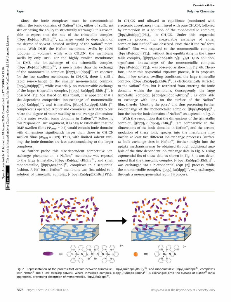
in CH3CN and allowed to equilibrate (monitored withelectronic absorbance), then rinsed with pure CH3CN, followedby immersion in a solution of the monometallic complex,[(bpy)2Ru(dpp)](PF6)2, in CH3CN. Under this sequentialexposure process, no measurable exchange of eithercomplex into Nafion® was observed. Note that if the Na+-formNafion® film was exposed to the monometallic complex,[(bpy)2Ru(dpp)](PF6)2, without first equilibrating in the trime-tallic complex, [{(bpy)2Ru(dpp)}RhBr2](PF6)5/CH3CN solution,significant ion-exchange of the monometallic complex,[(bpy)2Ru(dpp)](PF6)2, was observed as shown in Fig. 6b. There-fore, under this sequential exposure process, it is proposedthat, in low solvent swelling conditions, the large trimetalliccomplex, [{(bpy)2Ru(dpp)}2RhBr2]
5+, is electrostatically attractedto the Nafion® film, but is restricted from entering the ionicdomains within the membrane. Consequently, the largetrimetallic complex, [{(bpy)2Ru(dpp)}2RhBr2]
5+, is only ableto exchange with ions on the surface of the Nafion®
film, thereby “blocking the pores” and thus preventing furtherion-exchange of the monometallic complex, [(bpy)2Ru(dpp)]
2+,into the interior ionic domains of Nafion®, as depicted in Fig. 7.
With the recognition that the dimensions of the trimetalliccomplex, [{(bpy)2Ru(dpp)}2RhBr2]
5+, are comparable to thedimensions of the ionic domains in Nafion®, and the accom-modation of these ionic species into the membrane mayinvolve at least two different ion-exchange processes (surfacevs. bulk exchange sites in Nafion®), further insight into theuptake mechanism may be obtained through additional ana-lysis of the time dependent ion-exchange data in Fig. 6. Usingexponential fits of these data as shown in Fig. 8, it was deter-mined that the trimetallic complex, [{(bpy)2Ru(dpp)}2RhBr2]
5+,was exchanged via a biexponential (eqn (2)) process, whilethe monometallic complex, [(bpy)2Ru(dpp)]
2+, was exchangedthrough a monoexponential (eqn (3)) process.
Fig. 7 Representation of the process that occurs between trimetallic, [{(bpy)2Ru(dpp)}2RhBr2]5+, and monometallic, [(bpy)2Ru(dpp)]
2+, complexeswith Nafion® and a low swelling solvent. Where trimetallic complex, [{(bpy)2Ru(dpp)}2RhBr2]
5+, is exchanged onto the surface of Nafion® ionicaggregates, preventing absorption of monometallic, [(bpy)2Ru(dpp)]
2+.
Paper Polymer Chemistry
6876 | Polym. Chem., 2015, 6, 6870–6879 This journal is © The Royal Society of Chemistry 2015
Ope
n A
cces
s A
rtic
le. P
ublis
hed
on 1
8 A
ugus
t 201
5. D
ownl
oade
d on
17/
03/2
016
04:1
3:26
. T
his
artic
le is
lice
nsed
und
er a
Cre
ativ
e C
omm
ons
Attr
ibut
ion-
Non
Com
mer
cial
3.0
Unp
orte
d L
icen
ce.
View Article Online

½tir�Nafion ¼ 0:77½tri�ie�0:045t þ 0:23½tri�ie�0:00061t ð2Þ
½mono�Nafion ¼ ½mono�ie�0:014t ð3ÞIn agreement with the results of the sequential exposure
analysis (above) and behavior common to other ion-exchangematerials,41,42 the biexponential uptake of the trimetalliccomplex, [{(bpy)2Ru(dpp)}2RhBr2]
5+, is attributed to a fast ion-exchange of the complex with the surface accessible sulfonategroups, followed by a somewhat slower diffusion of these com-plexes into the interior of the membrane (exchange with bulksulfonates). In contrast, the smaller dimensions of the mono-metallic complex, [(bpy)2Ru(dpp)]
2+, yield a lower diffusivebarrier for exchange with bulk sulfonate sites and thus lesscontrast in time-dependence between the surface ion-exchangeand internal ion-exchange processes.
Although essentially no uptake in the less swelling CH3CNsolution (Fig. 6b) was observed for the trimetallic complex,[{(bpy)2Ru(dpp)}2RhBr2]
5+, at a 1 : 1 charge ratio of trimetalliccomplex, [{(bpy)2Ru(dpp)}2RhBr2]
5+, to –SO3− in Nafion®, it is
important to note that the equilibrated films had a slight colorchange that could not be removed by rinsing with various sol-vents. Surface ion-exchange experiments were performed witha large excess of Nafion® (1 : 100 and 1 : 50 charge ratios of tri-metallic complex, [{(bpy)2Ru(dpp)}2RhBr2]
5+, to SO3− groups)
and analyzed by electronic absorbance. The rate of surfaceexchange of the complex under these conditions followed amonoexponential trend and was found to be dependent on the
surface area of the Nafion® films. The trimetallic complex,[{(bpy)2Ru(dpp)}2RhBr2]
5+, was exchanged at a faster rate witha higher surface area of Nafion®. This evidence furthersupports our theory that the overall uptake of the large tri-metallic complex, [{(bpy)2Ru(dpp)}2RhBr2]
5+, is governed byion-exchange onto the surface of the Nafion® film.
Conclusions
We have demonstrated that the large trimetallic complex,[{(bpy)2Ru(dpp)}2RhBr2]
5+, readily absorbs into Nafion® viaion-exchange under appropriate solvent swelling conditions.This facile exchange is remarkable due to the calculated sizeof the trimetallic complex, [{(bpy)2Ru(dpp)}2RhBr2]
5+, in com-parison to proposed dimensions of Nafion® ionic aggregates.In order to accommodate these large molecules, it is reason-able to rationalize a more open channel morphology over themore confining morphology of the cluster-network model.It has been determined that up to 86 ± 2% of the –SO3
−
groups in Nafion® can be counterbalanced by the trimetalliccomplex, [{(bpy)2Ru(dpp)}2RhBr2]
5+, and the morphology ofthe ionomer is not significantly altered upon exchange ofthe metal complex. Furthermore, consistent with otherion exchange materials, Nafion® has a greater affinity forthe ion with the higher charge: the trimetallic complex,[{(bpy)2Ru(dpp)}2RhBr2]
5+, over the monometallic complex,[(bpy)2Ru(dpp)]
2+. Due to this higher affinity for the trimetalliccomplex, [{(bpy)2Ru(dpp)}2RhBr2]
5+, the half-life of ion-exchange in more swollen films is observed to be fasterthan that of the monometallic complex, [(bpy)2Ru(dpp)]
2+. Inless swollen films, exchange of the trimetallic complex,[{(bpy)2Ru(dpp)}2RhBr2]
5+, is not observed in a measurablequantity. Investigation of the time dependent ion-exchange be-havior has led to the conclusion that absorption occurs via afast exchange of surface sulfonate groups followed by a slowexchange (via diffusion) of ions in the interior domains of theionomer. With a low swelling solvent, exposure of Nafion®
films to both the monometallic, [(bpy)2Ru(dpp)]2+, and trime-
tallic, [{(bpy)2Ru(dpp)}2RhBr2]5+, complexes, yielded negligible
exchange of either species. Given the higher affinity of Nafion®
for the trimetallic complex, [{(bpy)2Ru(dpp)}2RhBr2]5+, it is pro-
posed that the large complex exchanges with ions on thesurface of the film, thereby blocking access to the ionic aggre-gates and thus preventing subsequent exchange of the mono-metallic complex, [(bpy)2Ru(dpp)]
2+.Overall, the large size of the trimetallic complex,
[{(bpy)2Ru(dpp)}2RhBr2]5+, in comparison to the ionic aggre-
gates of Nafion® allows for solvent controlled ion-exchange ofthe metal complex. Further investigation is underway in orderto determine the effect of changing swelling conditions afterthe complex has been absorbed in the ionomer. Switching to alower swelling solvent after absorption could essentially “lock”the large metal complex in place and reduce deactivation ofphotoinduced excited states through intermolecular collisionsand vibrational relaxation. With this reduced deactivation, we
Fig. 8 Experimental data and fitting result of trimetalliccomplex, [{(bpy)2Ru(dpp)}2RhBr2]
5+, (a) and monometallic complex,[(bpy)2Ru(dpp)]
2+, (b) absorbed into Nafion® from a DMF solutionand fit to eqn (1) and (2) where [{(bpy)2Ru(dpp)}2RhBr2]
5+ = [tri] and[(bpy)2Ru(dpp)]
2+ = [mono].
Polymer Chemistry Paper
This journal is © The Royal Society of Chemistry 2015 Polym. Chem., 2015, 6, 6870–6879 | 6877
Ope
n A
cces
s A
rtic
le. P
ublis
hed
on 1
8 A
ugus
t 201
5. D
ownl
oade
d on
17/
03/2
016
04:1
3:26
. T
his
artic
le is
lice
nsed
und
er a
Cre
ativ
e C
omm
ons
Attr
ibut
ion-
Non
Com
mer
cial
3.0
Unp
orte
d L
icen
ce.
View Article Online

anticipate enhanced catalytic activity in these new guest–hostsystems.
Acknowledgements
Acknowledgement is made to Virginia Tech Department ofChemistry, Institute for Critical Technology and AppliedScience (ICTAS) Sustainable Energy Laboratory, Department ofEnergy DE FG02-05-ER15751, and National Science Foundationunder Grant No. DMR-0923107 for their generous funding.The authors would also like to thank Douglas Atwater for hisassistance with programming and images.
References
1 R. B. Moore, J. E. Wilkerson and C. R. Martin, Anal. Chem.,1984, 56, 2572–2575.
2 K. A. Mauritz and R. B. Moore, Chem. Rev., 2004, 104,4535–4586.
3 G. C. Dismukes, R. Brimblecombe, G. A. N. Felton,R. S. Pryadun, J. E. Sheats, L. Spiccia and G. F. Swiegers,Acc. Chem. Res., 2009, 42, 1935–1943.
4 H. Park, Y. Park, E. Bae and W. Choi, J. Photochem. Photo-biol., A, 2009, 203, 112–118.
5 R. Ramaraj, A. Kira and M. Kaneko, Polym. Adv. Technol.,1995, 6, 131–140.
6 F. Taguchi, T. Abe and M. Kaneko, J. Mol. Catal. A: Chem.,1999, 140, 41–46.
7 L. Kavan and M. Graetzel, Electrochim. Acta, 1989, 34, 1327–1334.
8 H. Shiroishi, T. Shoji and M. Kaneko, J. Mol. Catal. A:Chem., 2002, 187, 47–54.
9 G. J. Yao, T. Onikubo and M. Kaneko, Electrochim. Acta,1993, 38, 1093–1096.
10 J.-M. Zen, S.-L. Liou, A. S. Kumar and M.-S. Hsia, Angew.Chem., Int. Ed., 2003, 42, 577–579.
11 J. Park, J. Yi, T. Tachikawa, T. Majima and W. Choi, J. Phys.Chem. Lett., 2010, 1, 1351–1355.
12 E. Krausz, J. Chem. Soc., Faraday Trans. 1, 1988, 84, 827–840.
13 T. D. Gierke, G. E. Munn and F. C. Wilson, J. Polym. Sci.,Polym. Phys. Ed., 1981, 19, 1687–1704.
14 W. Y. Hsu and T. D. Gierke, J. Membr. Sci., 1983, 13, 307–326.
15 J. Redepenning and F. C. Anson, J. Phys. Chem., 1987, 91,4549–4553.
16 K. Schmidt-Rohr and Q. Chen, Nat. Mater., 2008, 7,75–83.
17 L. Li, L. Duan, Y. Xu, M. Gorlov, A. Hagfeldt and L. Sun,Chem. Commun., 2010, 46, 7307–7309.
18 L. Rubatat, A. L. Rollet, G. Gebel and O. Diat, Macro-molecules, 2002, 35, 4050–4055.
19 J. Li, J. K. Park, R. B. Moore and L. A. Madsen, Nat. Mater.,2011, 10, 507–511.
20 R. S. McLean, M. Doyle and B. B. Sauer, Macromolecules,2000, 33, 6541–6550.
21 F. P. Orfino and S. Holdcroft, J. New Mater. Electrochem.Syst., 2000, 3, 287–292.
22 J. K. Park, J. Li, G. M. Divoux, L. A. Madsen andR. B. Moore, Macromolecules, 2011, 44, 5701–5710.
23 S. C. Yeo and A. Eisenberg, J. Appl. Polym. Sci., 1977, 21,875–898.
24 J. A. Elliott, D. Wu, S. J. Paddison and R. B. Moore, SoftMatter, 2011, 7, 6820–6827.
25 M. K. Mistry, N. R. Choudhury, N. K. Dutta, R. Knott,Z. Shi and S. Holdcroft, Chem. Mater., 2008, 20, 6857–6870.
26 L. Rubatat, G. Gebel and O. Diat, Macromolecules, 2004, 37,7772–7783.
27 S. M. Arachchige, J. Brown and K. J. Brewer, J. Photochem.Photobiol., A, 2008, 197, 13–17.
28 S. M. Arachchige, J. R. Brown, E. Chang, A. Jain,D. F. Zigler, K. Rangan and K. J. Brewer, Inorg. Chem., 2009,48, 1989–2000.
29 M. Elvington, J. Brown, S. M. Arachchige and K. J. Brewer,J. Am. Chem. Soc., 2007, 129, 10644–10645.
30 J. L. Colon and C. R. Martin, Langmuir, 1993, 9, 1066–1070.
31 C. R. Martin, I. Rubinstein and A. J. Bard, J. Am. Chem.Soc., 1982, 104, 4817–4824.
32 M. N. Szentirmay, N. E. Prieto and C. R. Martin, J. Phys.Chem., 1985, 89, 3017–3023.
33 M. J. Frisch, G. W. Trucks, H. B. Schlegel, G. E. Scuseria,M. A. Robb, J. R. Cheeseman, G. Scalmani, V. Barone,B. Mennucci, G. A. Petersson, H. Nakatsuji, M. Caricato,X. Li, H. P. Hratchian, A. F. Izmaylov, J. Bloino, G. Zheng,J. L. Sonnenberg, M. Hada, M. Ehara, K. Toyota,R. Fukuda, J. Hasegawa, M. Ishida, T. Nakajima,Y. Honda, O. Kitao, H. Nakai, T. Vreven, J. A. MontgomeryJr., J. E. Peralta, F. Ogliaro, M. J. Bearpark,J. Heyd, E. N. Brothers, K. N. Kudin, V. N. Staroverov,R. Kobayashi, J. Normand, K. Raghavachari, A. P. Rendell,J. C. Burant, S. S. Iyengar, J. Tomasi, M. Cossi,N. Rega, N. J. Millam, M. Klene, J. E. Knox, J. B. Cross,V. Bakken, C. Adamo, J. Jaramillo, R. Gomperts,R. E. Stratmann, O. Yazyev, A. J. Austin, R. Cammi,C. Pomelli, J. W. Ochterski, R. L. Martin, K. Morokuma,V. G. Zakrzewski, G. A. Voth, P. Salvador, J. J. Dannenberg,S. Dapprich, A. D. Daniels, Ö. Farkas, J. B. Foresman,J. V. Ortiz, J. Cioslowski and D. J. Fox, Gaussian, Inc.,Wallingford, CT, USA, 2009.
34 W. E. Cooley, C. F. Liu and J. C. Bailar, J. Am. Chem. Soc.,1959, 81, 4189–4195.
35 M.-H. Kim, C. J. Glinka, S. A. Grot and W. G. Grot, Macro-molecules, 2006, 39, 4775–4787.
36 B. Loppinet, G. Gebel and C. E. Williams, J. Phys. Chem. B,1997, 101, 1884–1892.
37 S. Logette, C. Eysseric, G. Pourcelly, A. Lindheimer andC. Gavach, J. Membr. Sci., 1998, 144, 259–274.
38 D. Reichenberg, J. Am. Chem. Soc., 1953, 75, 589–597.
Paper Polymer Chemistry
6878 | Polym. Chem., 2015, 6, 6870–6879 This journal is © The Royal Society of Chemistry 2015
Ope
n A
cces
s A
rtic
le. P
ublis
hed
on 1
8 A
ugus
t 201
5. D
ownl
oade
d on
17/
03/2
016
04:1
3:26
. T
his
artic
le is
lice
nsed
und
er a
Cre
ativ
e C
omm
ons
Attr
ibut
ion-
Non
Com
mer
cial
3.0
Unp
orte
d L
icen
ce.
View Article Online

39 D. K. Hale and D. Reichenberg, Discuss. Faraday Soc., 1949,7, 79–90.
40 K.-D. Kreuer and G. Portale, Adv. Funct. Mater., 2013, 23,5390–5397.
41 R. Turse and W. Rieman, J. Phys. Chem., 1961, 65, 1821–1824.
42 M. Hatanaka and M. Hoshi, J. Appl. Polym. Sci., 2014, 131,39358.
Polymer Chemistry Paper
This journal is © The Royal Society of Chemistry 2015 Polym. Chem., 2015, 6, 6870–6879 | 6879
Ope
n A
cces
s A
rtic
le. P
ublis
hed
on 1
8 A
ugus
t 201
5. D
ownl
oade
d on
17/
03/2
016
04:1
3:26
. T
his
artic
le is
lice
nsed
und
er a
Cre
ativ
e C
omm
ons
Attr
ibut
ion-
Non
Com
mer
cial
3.0
Unp
orte
d L
icen
ce.
View Article Online