six-degree-of-freedom (6-dof) simulator for weapon …technical report artsd-tr 81002...
TRANSCRIPT

f\Xy/\m 52(*
™rf-//3 3-3 & AD-E400 798
TECHNICAL REPORT ARTSD-TR 81002
SIX-DEGREE-OF-FREEDOM (6-DOF) SIMULATOR
FOR WEAPON TESTING
TECHNICAL LIBRARY DONALD E. FRERICKS
ROBERT J. RADKIEWICZ
MARCH 1982
US ARMY ARMAMENT RESEARCH AND DEVELOPMENT COMMAND TECHNICAL SUPPORT DIRECTORATE
DOVER, NEW JERSEY
APPROVED FOR PUBLIC RELEASE; DISTRIBUTION UNLIMITED.

The views, opinions, and/or findings contained in this report are those of the author and should not be construed as an official Department of the Army position, policy or decision, unless so desig- nated by other documentation.
Destroy this report when no longer needed. Do not return to the originator.
The citation in this report of the names of com- mercial firms or commercially available products or services does not constitute official endorse- ment or approval of such commercial firms, prod- ucts, or services by the US Government.

UNCLASSIFIED SECURITY CLASSIFICATION OF THIS PAGE (When Data Entered)
REPORT DOCUMENTATION PAGE 1. REPORT NUMBER
Technical Report ARTSD-TR-81002
2. GOVT ACCESSION NO.
4. TITLE (and Subtitle)
SIX-DEGREE-OF-FREEDOM (6-DOF) SIMULATOR FOR WEAPON TESTING
READ INSTRUCTIONS BEFORE COMPLETING FORM
3. RECIPIENT'S CATALOG NUMBER
5. TYPE OF REPORT & PERIOD COVERED
Final 6. PERFORMING ORG. REPORT NUMBER
7. AUTHORO)
Donald E. Frericks Robert J. Radkiewicz
9- PERFORMING ORGANIZATION NAME AND ADDRESS
ARRADCOM, TSD Ware Simulation Section (DRDAR-TSE-SW) Rock Island, IL 61299
11. CONTROLLING OFFICE NAME AND ADDRESS
ARRADCOM, TSD STINFO Div (DRDAR-TSS) Dover. NJ 0 7801
14. MONITORING AGENCY NAME ft ADDRESS(7/ ditterent horn Controlling Olllce)
ARRADCOM, TSD Test and Instrumentation Div (DRDAR-TSE-S) Dover, NJ 07801
8. CONTRACT OR GRANT NUMBERfsJ
10. PROGRAM ELEMENT, PROJECT, TASK AREA 4 WORK UNIT NUMBERS
AMS Code 3297.06.7313 (cont) 12. REPORT DATE
March 1982 13- NUMBER OF PAGES
39 15. SECURITY CLASS, (ol thla report)
Unclassified 15«. DECLASSIFI CATION/DOWN GRADING
SCHEDULE
16. DISTRIBUTION STATEMENT (ol thla Report)
Approved for public release; distribution unlimited.
17. DISTRIBUTION STATEMENT (of the abatract entered In Block 20, It different from Report)
Tntr^Z^TfT5 .The dfeta±led desi8n st^y performed by the Franklin Insti-
tute Research Laboratory for the simulator provides more complete details and is published separately as a special publication (ARTSD-SP-81001).
The mechanical and electrical design drawings for the 6-D0F simulator are on file at the Ware Simulation Section.
19. KEY WORDS (Continue on reverse aide If necessary end Identify by block number)
Control system Six degrees-of-freedom Hydraulics Spring rate Pit:ch Vibration Simulator Weapons Yaw
2Q' ABSTRACT fCorrt&ue la nnram 55 tt RMMMgl and Identify by block number) '
A six-degree-of-freedom (6-DOF) simulator has been constructed and imple- mented as a test bed for military vehicles or individual weapon systems. These weapon systems are either attached directly to the simulator or connects to
flrin^da^l SUSpended.from "• Simulation includes firing and res^ns^ to firing loads using appropriate conversion and movement which parallels weapon firing in the field. While firing, the weapon system can be moved in either
?rom^ f^TnT m0t:LOn ^iT ^ a S:L8nal generator « implex motion obtained from a field tape operated by a digital computer. Vibrations typical (cont)
nr\ FORM im ' r ' ' "V » JAM 73 14/3 EDITION OF I MOV 65 IS OBSOLETE
UNCLASSIFIED SECURITY CLASS!FICATIOM OF THIS PAGE (Whm Data Entered)

OMMaSIZIED SECUmTY CLASSIFICATION OF THIS PAGEnW.«."H^7i^;rfJ
Block 10 (cont)
Projects no. 6737313, 6747313, 6767313, and 6777313.
Block 20 (cont)
of the field environment are input through the actuator.
UNCLASSIFIED
SECURITY CLASSIFICATION OF THIS PAGECWhen DaM Entered)

CONTENTS
Page
Introduction 1
Background 1 Advantages of Laboratory Testing 2
Description of Passive Simulator 2
Activation of the 6-DOF Simulator 4 Modification of the Triogonal Actuator System 4 Additional Hydraulic Power Supplies 4 Modifications to Control Panel 6 Automated Spring Rate Control 7
Single Axis Control System 7
Installed Pitch and Yaw Motions 12 Math Model 13 Computer Implementation of Math Model 15
Turret Adaptor 16
Expansion of Data Acquisition and Reduction System 16
Conclusions 18
Distribution List 31

TABLES
Page
1 Design objectives for activating the passive simulator 5
2 Required flow rates for full power simultaneous operation of all systems 6
FIGURES
1 Passive simulator with UH-1B helicopter suspended from mounting platform 19
2 Passive 6-DOF simulator control console 20
3 Active 6-DOF simulator control console 21
4 Linearized math model of a hydraulic actuator position control system 22
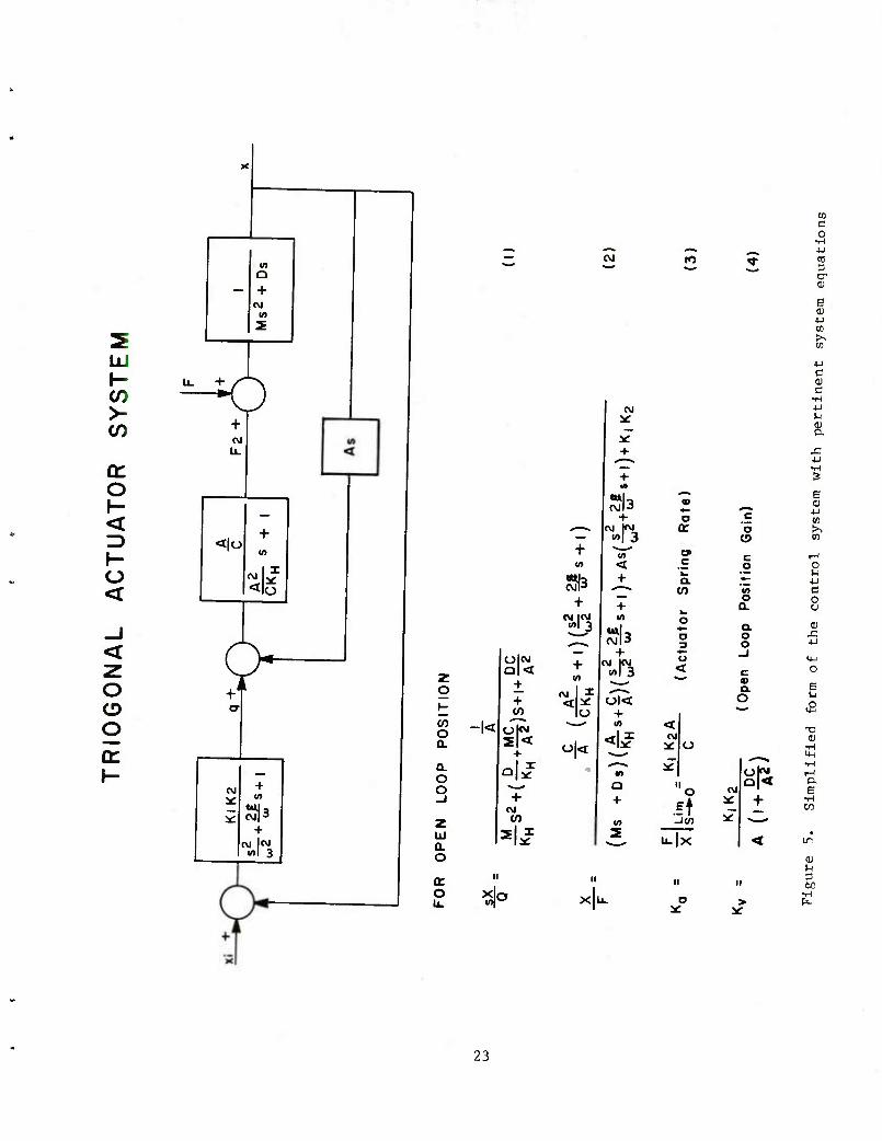
5 Simplified form of the control system with pertinent system equations 23
6 Simplified block diagram of adaptive spring rate control system 24
7 Block diagram of force detection circuit 2 5
8 Block diagram of complete triogonal actuator system 26
9 Allowable spring rates as limited by servovalve leakage and load mass 27
10 Turret adaptor suspended from 6-DOF simulator 28
11 Data acquisition room after expansion to support 6-DOF simulator 29

INTRODUCTION
Background
An activated slx-degree-of-freedom (6-DOF) simulator has been designed constructed, and tested under several Production Engineering Measures (PEM) pro- jects extending over many years. The project numbers are listed on the preceding Report Documentation Page for reference. This report outlines accomplishments achieved under these projects and provides the capabilities of the activated 6- uuf simulator.
4 ^ IS6 n6"0017 slmulator ls a test bed to which sections of military vehicles or individual weapon systems are attached. The weapon systems, whether attached either directly to the simulator or attached to vehicle sections that are sus- pended from the simulator, are fired and the simulator responds to the firing loads In the three translatlonal and the three rotational degrees of freedom which parallels weapon firing in the field instead of in a laboratory. ' The weapon system may be simultaneously moved in either yaw or pitch motion. The motions may be simple harmonic motion driven by a signal generator or complex motion obtained from a field tape driven by a digital computer. Vibrations typ- ical of the desired field environments can be input through the hydraulic actu- ator system. The simulator is thus capable of providing a more realistic test environment in terms of the mechanical characteristics, typical vibrations, and motions than has previously been possible.
Classical methods for the acceptance testing of automatic weapons usually ^« V functlon-flrin8 test ^der a single specified mounting condition. Such tests are a go or no-go inspection at a single point in the spectrum of dynamic conditions under which weapons are expected to operate in the field. This type of testing is adequate for low rate-of-flre weapons of the past but lacks the capability for discriminating between reliable and unreliable weapons of the high rate-of-fire type that are intended for Installation on highly flexible, moving.
TcrZ It ^J™ fatuf0rms' A truly definitive acceptance test must includl
active simulation of the structural vibrations induced by vehicle motion during the course of testing. s
tTohriedsetmRn d?orgn^S,:Ud7 Per/0rmed by the Franklin Institute Research Labora- tories (FIRL) for the simulator provides more complete details of the overall
ST^S"d81001).PUbli8hed SeParately ^ a —P-^ng special publication

Advantages of Laboratory Testing
Both in cost savings and technical data obtained, the laboratory testine of
the number of test and safety personnel. reduction in
This report explains the modifications that were made to t-h« e^..i ,- converting from passive to active which makes it ca^le^f pSvl^t^d^^
tLflrron theeSCmrobed ^ M^ PreViOUS ^^^' ^hese modification^ pro^de the fire on-the-move capability required for simultaneous two-axis evaluation of new weapons with stabilization systems. evaluation of
The objective of PEM Project 6737313 was to improve the existing test nro- cedures for production and acceptance testing of weapon svstemV TM/ A
by applying the latest technology to assure 'that ^p" perf^mknce conSms " standards associated with coupling of weapon-mount air/rame or "round comblt In^ 6 no. ff^^h this purpose, the project required modifying the eTst-
DESCRIPTION OF PASSIVE SIMULATOR
The passive 6-DOF simulator (fig. l) WaS designed and built by the Franklin Institute Research Laboratories (FIRL) from five component systems: (T) the support and fork structure. (2) the yaw gimbal. (3) the pitJ gimb^l. 4 the trxogonal actuator suspension, and (5) electronic and control consoles. The
cupo a" or "the0/ TT^ *■ fUll"SiZe helicoPter hull, a lightweight tLk cupola, or other vehicle sections weighing up to 9100 kg. The simulator was capable of absorbing the firing impulses of a 30-mm weapon. Hydraulic brakes
L The LTnffo^ ^ POSltr- The displacements of'the system in respoL: to the firing loads were in the three translational and the three rotational degrees-of-freedom; the displacements, however, were highly coupled.
^^ The Pfssive syff> ^d hand-operated controls for statically positioning a test vehicle suspended from the simulator at different yaw and pitch angLs to set initial test conditions for off-axis firing of weapons. This permitted the weapon system to be counter-rotated to maintain projectile impact'in the sand
nnJ ^i T"' thejweap0nS C0Uld be fired at the initial Preset angles only and not while the yaw and pitch angles were being altered.

The spring rate and damping characteristics of the passive simulator were determined hy proper selection and adjustment of the pressures and volumes con- tained In the suspension actuator assemhlles. Each of the suspension actuator assemblies consisted of a double-ended actuator having a total stroke of 22.0 cm, a bore of 15.3-cra diameter, and a rod of 7.6-cm diameter giving a piston working area of 136.R cmz (piston area minus rod area).
Attached to the outer shell of the actuator chambers were two accumulators, one of which was piped to the top while the other was piped to the bottom cham- ber. Each accumulator had an oil-containing volume of 3.80 L and a nitrogen- containing volume of 3.85 L. The oil and nitrogen were separated by a movable piston, and a hand valve was inserted in the piping lines between the actuators and the accumulators to provide variable damping.
By proper selection of the variable parameters, the suspension system could be set to the desired spring rate, and damping ratios could be set by opening or closing the hand valves. Spring rates were obtained by the action of compressing a contained volume of nitrogen. Changes in spring rate were produced by changing the Initial gas pressure, or volume, or both. Damping was obtained by directing the actuator fluid flow through a control orifice, and changing the size of the orifice varied the amount of damping. A complete description of the parameters affecting the spring rate and damping and the procedure for its adjustment are given in referenced technical manual.
The time-consuming procedure for changing the spring rate and damping char- acteristics of the system involved the use of 12 hand-operated valves. When firing began, the spring rate Increased along with the pressure in the hydraulic cylinders. The static spring rate Initially set in the hydraulic cylinders changed as the dynamics of the system emerged. To achieve the full potential of the simulator, a method for maintaining a constant spring rate and damping coef- ficient was required.
Although the simulator absorbed the firing loads and responded to these loads in the three translational and the three rotational degrees^)f-freedom no external vibrations could be input to the weapon system. The mechanical charac- teristics were present, but the vibrational dynamic field environment in which the weapon system must operate could not be generated thereby negating the use of the passive simulator in its present state.
The requirement for testing weapons with two-axis stabilization systems Indicated the need for activating the passive simulator. The test requirements warrant the use of a simulator with the capability of absorbing firing loads while the weapon system is being moved in combined yaw and pitch motions.
2 .. Helicopter Fuselage Mount Simulator," Technical Manual for Project No. C-2715
Contract DAAAF01-70-C-0406, Section III, November 1972, pp. 5-22.
Activation of the 6-DOF Simulator
Design Specifications
vation Thl PaS.SlfT 6?0F Simulator squired several modifications before acti-
-ri^co^a^^^f^^rr ^ the aPP-xi-te order in whiL hey listed in table 1.' actlvated simulator was to achieve the design objectives7
Modification of the Tiogonal Actuator System3
fled by adding sleeves to £c^'tl 'dta^e/of tta^SUfr"T^^'Sr
^ ■^T-J* *. actuator pistons were determined by the required flow rate. These changes were incorporated into the system in FY 75. requlred flow
uh^hA detailedj discussion of the design philosophy is given in ARTSD-SP-810ni which corresponds to this report. s-^veu xu AKISU bF aiuui,
Additional Hydraulic Power Supplies
supply"6 VesiL™ t^fT* T8 eqUiPPed With 0nly a 30 L/min hydraulic power supply. Design calculations for the activated simulator are shown in table 2.
3 Triogona! Actuat:or System> This ^ ^ assemb ^
hyd a"^^3 ^torTi"13"5111^ ^ ^^ ^ COnneCted at ^ vertices by six that ii a seoarL. f Z1SZag P;attern* ^ entire aSSembly is an octahedron, tnat is, a separate frame composed of eight triangles.

c
3 6
>
d P-
td >
CJ
o
CO
>
XI T3 « « p U
&c A: •* 00 • (-( o iH •
u o 1 o ■H CM 1 h O 4J ccT 4-1 o 01 JJ
X 1 T3 cd 13
o lJ CC
<r ^
2 s o o c <r
«* «*
B5
c c o ■*
B 5 o o o <t
+
ro m
C en o CB e OJ
m
"0 CD
to 1
o oc
CN
T—1 • O C •
o -H ■w
o o c
o o m
l
c H
1
o 0 s
0 in
+
o IT*;
t
H rH T-* & c c c ■O o c o •H
o o o e fl *, M
o o o h in in in c ro CM CNJ 4-1
O O O a 4-J 4-J 4-) 4-1
O O O o < in in in
CN eg CM
N
0 • in
0)
C • 1 ro ja
ts CE
H
o C C
o
-H ■H
0) c
■H
c 0)
o
o 4-1
e
U i-i
4J O 0)
•I— ,c o c
en o) P
,fi
■o 0)
^ p
s Bl x: 0) CO P 3 0J
4-J CO ^0 cd 4-1 OJ 0)
H
4-1
00
4-J c OJ
C 0J e o; o
4-1
CO
CO
OJ
.-1 CJ
o 4-1
0) « •H | 0 c C e •H 5 CO «H CO •H s 0) CO o o o 4-) s u X H 4-J 9 o H 0) •H •H •H ■H >1 (U 0J 3 c W a. 4-1 4-1 4-J 4-1 CO 4-) > P. co 0) •O 1-J CO CO u CJ CJ a 73 a. B C TO 0) a ■H u OJ OJ 0) c o 4-1 •H o co ■a en ■c M u u CO CJ CO ■H w c •H M ■H TJ •H i—i •H ,c bC 4-J
<u "O je B ■c T) "O CO X rH E C CO Pi o ■H 1 O 0J o ■H U CO s 4J l-< X >. N 4-J P3 O ^ JZ D cO •H PH o •H <H •H
CO N pu CO £ P^ fc >
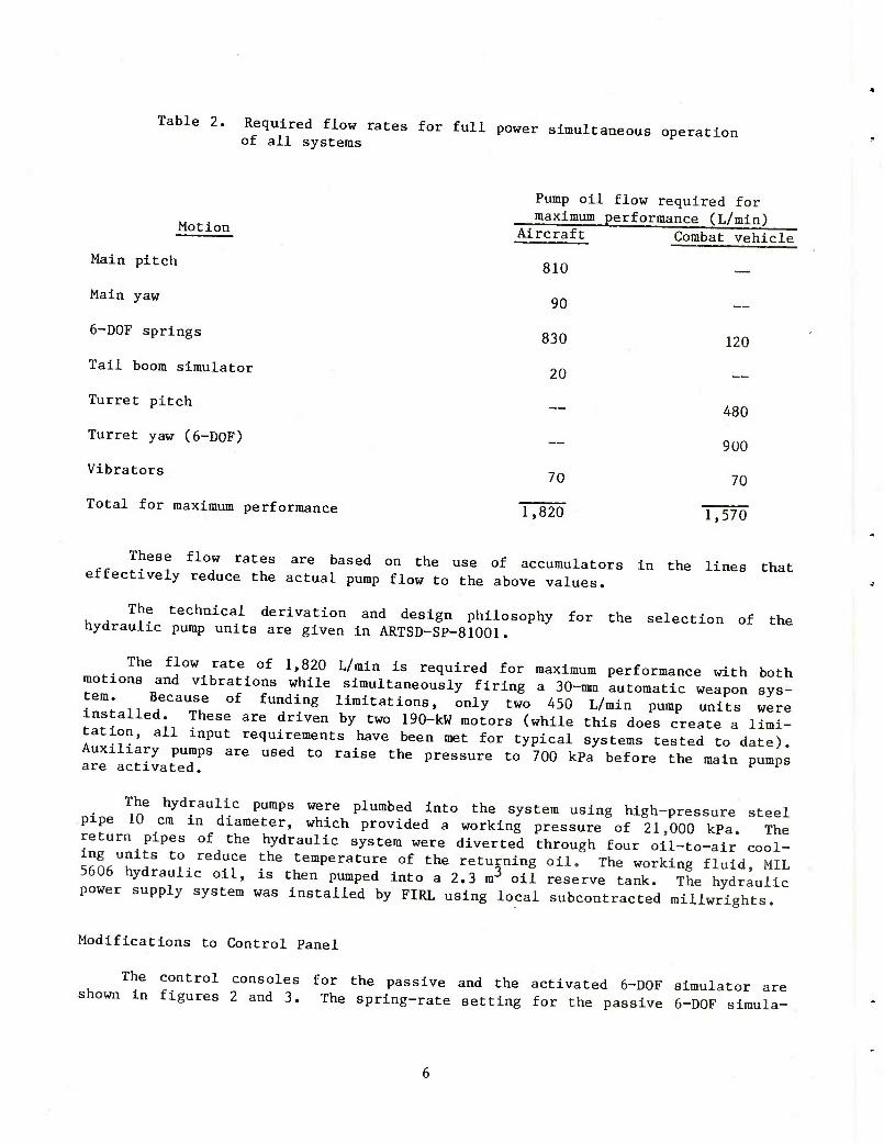
Table 2. Required flow rates for full power simultaneous operation of all systems
Motion
Main pitch
Main yaw
6-DOF springs
Tail boom simulator
Turret pitch
Turret yaw (6-DOF)
Vibrators
Total for maximum performance
Pump oil flow required for maximum performance (L/min)
Aircraft Combat vehicle
810
90
830
20
70
120
480
900
70
1,820 1,570
These flow rates are based on the use of accumulators in the lines that effectively reduce the actual pump flow to the above values.
hvHr- ^ techa±ca} Privation and design philosophy for the selection of the nydraulxc pump units are given in ARTSD-SP-81001.
The flow rate of 1,820 L/min is required for maximum performance with both motions and vibrations while simultaneously firing a 30-mm automatic weapon sys- tem. Because of funding limitations, only two 450 L/min pump units were installed. These are driven by two 190-kW motors (while this does create a limi- tation, all input requirements have been met for typical systems tested to date). Auxiliary pumps are used to raise the pressure to 700 kPa before the main pumps are activated. K F
nfno m6 hydraul
Iic PuraPs were Pished into the system using high-pressure steel
pipe 10 cm In diameter, which provided a working pressure of 21,000 kPa. The return pipes of the hydraulic system were diverted through four oil-to-air cool- Sn^h ^ t°Ied^?e the temperature of the returning oil. The working fluid, MIL 5606 hydraulic oil, is then pumped into a 2.3 m3 oil reserve tank. The hydraulic power supply system was installed by FIRL using local subcontracted millwrights.
Modifications to Control Panel
The control consoles for the passive and the activated 6-DOF simulator are shown m figures 2 and 3. The spring-rate setting for the passive 6-DOF Simula-

tor required the hand adjustment of 12 valves. The procedure was time consuming, and a number of attempts to achieve the spring rate were required. The spring ^ /0r. ^ aci
tivated Emulator is programmable and is automatically adjusted to the desired value. A unique closed-loop model following servo control system maxntains the spring rate at the desired setting.
^ ^r6^ ^^^ ^^ added t0 the COntro1 Panel that indicate the status of oil fi^ H
U?
SyStTu TheSe meterS indicate o" temperature, oil level, and oil filter condition. There are also controls for positioning the simulato^ and meters for indicating platform position. These include readouts such as length of actuator pistons, yaw and pitch position, and controls for manually setting spring rate, mass, yaw and pitch position, and damping values.
t-rn! ^ Cl0ntT?1 panels were modified and installed by FIRL personnel. The con-
Tnl HT ^T^f alS0 haVe Plug"in ele^ronic cards that are part of the
ratfof1^ aTtuato^10^ ^^ ^^ ^ ^^ ^ C— —
Automated Spring Rate Control
moH lTi?i^aUliC aCtuators of the 6-DOF simulator are regulated by an adaptive model following control system. This system allows each actuator to be orl-
IZrslnTleTf*1*/ SPeCified SPri^-—^Ping model. T^^blnation' of each single-axis actuator system in the unique triogonal geometry provides an equivalent 6-DOF spring-mass-damping at the center of the simulator. ^^^
SINGLE AXIS CONTROL SYSTEM
identical6 ^JT^r " fSynmetrica1' the contro1 ^em for all six actuators is
fer/unct'lons P ThP 1^ ^ are u^ throughout ^e system to designate trans- fer functions The linearized math model of a hydraulic actuator position con-
hvHt.T '. f0™,11! figure 4. has a servovalve which controls fluid flow into a hydraulic piston with an attached effective mass (M). The control system ^
iid:Z£j rz\VTaxiZT:5'and pertinent —fu—s - ^ i
sX . I Q fs2 [|- +MC]S+1+DC (1)
^H KH A2 A2
. ^ f ^ ^ + ^ + l) Ul
n. (A) /.I i. £

F | Ki K2A
Ka " X I s^o = C~ Actuator spring rate) (3)
K1K2 Kv —; DTT (0Pen ioop position gain) /** A (l +i^j C*)
A
From equations 3 and 4. we can relate the actuator spring rate to the open
loop position gain if -^ « 1. A
For the 6-DOF simulator where
a = 68 cm2 , C < ii_E!L and D < 37W-Sec
N«sec cm
this Inequality Is true. Then the relationship hetween actuator spring rate and open loop position gain Is 8
KA2
K = V
a C (5)
Thus, hy controlling the open loop position gain, the hydraulic actuator spring rate can he controlled which Is the basis of the adaptive control system.
j* i 5 the4exlstln8 actuator control system, the open loop gain Is set near the
aoniLl r 8 ;ate; ThGn the force appiied to "he actuator is -—i *** applied to an adaptive model of a sprlng-mass-damplng system. The output of the model Is compared to the existing actuator displacement, and this error signal is used to vary the forward loop ^sltlon gain (K,). A simplified block diagram of this system is shown in figure 6. v ^ ^ uidgiam or
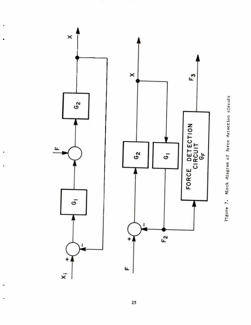
cirrJ^ 0n}y ^rtion of thls ™>del not discussed yet is the force detection circuit. In the present system, the force (F) applied to the actuator is not measured directly.
Instead, the pressure drop across the actuator is measured which is equiva- lent to measuring the actuator-generated force (F2). The force detection circuit operates on F2 to produce energy equivalent to the applied force.
7 uJ^ 0perflon of the force detection circuit is shown more clearly in figure 7 which contains a simplified version of figure 4. This figure shows that for F, + F It la necessary that 3
F3 F Cf-^ + ^ (6)

However, from the block diagram we obtain
F2 G^
1 + (LG, (7)
Combining equations 6 and 7 for Fo + F we obtain
F3 1 + G.G,
F2 0^2 C8)
Under conditions applicable to the existing actuators and substituting for G^^ and G2 (fig. 4), we find that
^3 = M_ 2 MC F2 KH 7 ^>
This system is simulated by adding a second order lag function in the denom- inator with poles located at frequencies much higher than the zeros of equation 7 •
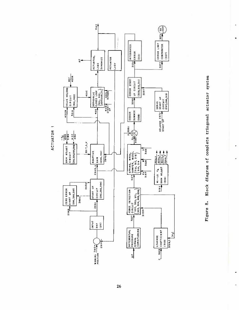
The block diagram for the complete triogonal actuator control system is shown in figure 8.H The numbers in each block refer to the electronic boards identified on drawing 26D-105 that perform the functions of each block. The major inputs to each block are identified by board number and pin. Careful con- sideration of the block diagram reveals that it is essentially the same as that in figure 6. There have been many significant additions, and these are discussed below.
To slowly bring the actuator from its hydro off position (actuator pushed down) to its command position, two start-up circuits have been added. These are the zero error start-up and the servo start-up circuits. Both circuits reduce overall system gain and slowly increase it to its full value as the system reaches equilibrium.
The gain adjust circuit provides fixed gains of 1.45, 0.42, or 0.19 in the forward loop depending on the spring rate and damping set in the system. The spring rate and damping operate relays which select one of the three gains.
This figure is directly related to FIRL drawing 26D-105, sheet 1, Triogonal Actuator Control System Electronics Schematic (Actuator 1).

The adaptive gain circuit varies the open loop gain of the system and pro- vides a voltage output based on position input (2X) and integrated error input
( — ) according to
V = 2X • (l +
Consider two cases
I £ = +10V s
0.09EI —r_j (10)
V = 2X • (1.9)
II - = -10W s
V = 2X • (0.1)
From these extremes the adaptive gain can vary over a 19 to 1 range.
Both the gain adjust and the adaptive gain circuits vary the system forward loop gain. The gain adjust circuit provides an adjustment of 7.63 to 1 and the adaptive gain circuit an adjustment of 19 to 1. As a result, the total forward loop gain can be varied over a 145 to 1 range. Since the forward loop gain is linearly proportional to the desired spring rate (see equation 5), the system spring rate can be varied over this same 145 to 1 ratio.
A valve-holding circuit has been added to account for steady state varia- tions presented by solutions to the adaptive model. With a mass attached to the actuator, a steady state applied force will be sensed by the force detection circuit and the model will provide a position output (Xc). The actuator, how- ever, will also try to follow its manual position command. The valve-holding circuit compensates for the resulting steady state position error.
The servovalve closed loop is a standard valve drive circuit. A dither circuit with f = 200 Hz has been added to reduce effects of stiction on system operation.
The force detection circuit is the same as explained previously with the following addition: The input to the system transfer function is normalized to prevent saturation and post multiplied to provide proper scaling. Consider equa- tion 9 again in more general form
F2 G (11)
The actuator force (F2) is normalized so that
10

p2 "-^l (12,
After multiplying N by G, we postraultlply F2 to obtain the desired result below
F3 = N • G ' |F2| = F2G (13)
The leakage coefficient of the, hydraulic actuator is controlled by a valve attached to a potentiometer. The leakage coefficient is required by the force detection circuit. This coefficient is given by
■^ (U)
where Q is the valve flow and P is the pressure drop across the load. This func- tion is nonlinear and closely approaches
c -/~r (15)
where B is linearly related to the valve opening. Also, p = F2/A so that
C 7=: (16)
which is implemented by the leakage coefficient circuit.
The Integrated error circuit was designed as shown in figure 3; however, a lead and lag network was added to improve system stability. The adaptive con- troller transfer function (H) is given by
H = 4.93 (1 + 2S) (1 + 0.0136s) s (1 + 0.0296s) (l7)
The final circuit Is the error limit comparator. This circuit provides a visual observation when the error exceeds a preset limit and can be used to stop weapon firing when the system error is too large.
The total system has been in operation for over two years and has proven extremely reliable. Some comments on its operation are as follows:
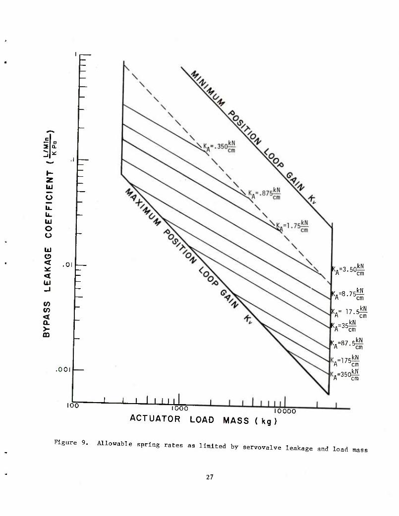
1. The achievable spring rates by the system are determined by the valve leakage coefficient and the load mass. This relationship Is shown in figure 9.
2. Damping control in this system is difficult since it is dependent on the leakage coefficient and is given by
11
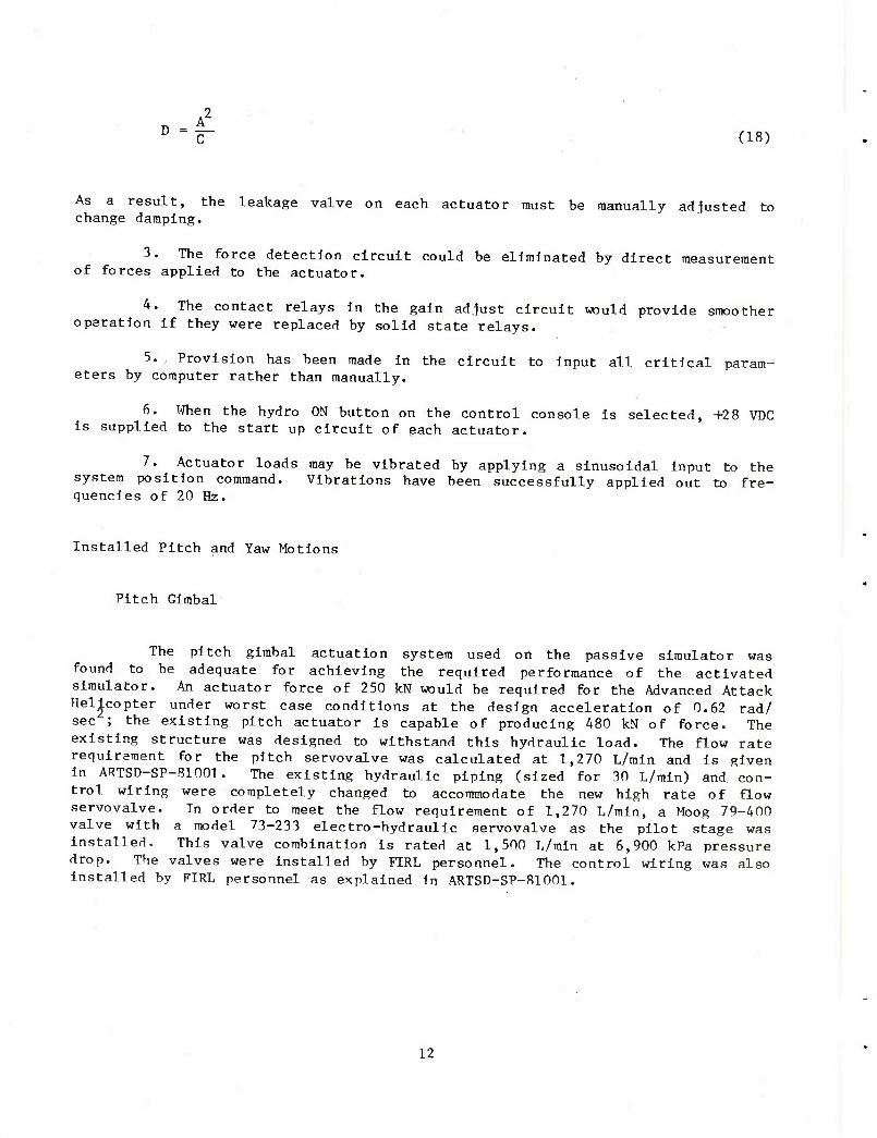
D " C^ (18)
As a result, the leakage valve on each actuator must be manually adiusted to change damping.
3. The force detection circuit could be eliminated by direct measurement of forces applied to the actuator.
4. The contact relays in the gain ad-just circuit would provide smoother operation if they were replaced by solid state relays.
5. Provision has been made In the circuit to Input all critical param- eters by computer rather than manually.
6. When the hydro ON button on the control console Is selected, +28 VDC Is supplied to the start up circuit of each actuator.
7. Actuator loads may be vibrated by applying a sinusoidal Input to the system position command. Vibrations have been successfully applied out to fre- quencies of 20 Hz.
Installed Pitch and Yaw Motions
Pitch Glmbal
The pitch glmbal actuation system used on the passive simulator was found to be adequate for achieving the required performance of the activated simulator. An actuator force of 250 kN would be required for the Advanced Attack Helicopter under worst case conditions at the design acceleration of 0.62 rad/ sec ; the existing pitch actuator Is capable of producing 480 kN of force. The existing structure was designed to withstand this hydraulic load. The flow rate requirement for the pitch servovalve was calculated at 1,270 L/mln and Is given In ARTSD-SP-B1001. The existing hydraulic piping (sized for 30 L/mln) and con- trol wiring were completely changed to accommodate the new high rate of flow servovalve. In order to meet the flow requirement of 1,270 L/mln, a Moog 79-400 valve with a model 73-233 electro-hydraulic servovalve as the pilot stage was Installed. This valve combination Is rated at 1,500 L/mln at 6,900 kPa pressure drop. The valves were Installed by FIRL personnel. The control wiring was also Installed by FIRL personnel as explained in ARTSD-SP-B1001.
12

Yaw Cltnbal
that of th* n.. , / , qUe f0r the actlvated syst™ Is ^ch greater than waf available for h^'T'. ^ ^ PaSSlve Systera' a ^dro/mechanical brake was available for holding the load under firing conditions. Because the acti- vated systen, requires a f ire-on-the-.ove capability, a brake systen, cannot be
for hh- °e8l8n calculations indicate that a yaw torque of 98 kNm was requried
Since ^rr./"^ hellc0Pter at the ^«i«n acceleration of 0.62 rad/sec^.
i^:q^tdr^caSwiv"Srs^he ^esive ^^ wrrated at u kNm' ^was
passive ^m„i^ r aCtlVa^ed system- The small capacity rotary actuator on the V*IJ J ff oooT3 rePlaced hy a iarger one manufactured by Hagglund. The fro'm 0 16" 83/5, h^ra-llc ™^ «** - -ted capacity of IU kS at speed^
prpelines lefdlnTto the v^l reqUlre ^ USe 0f r0ta^ ^raulic joints in the The hvdra.,1^ 7. the,Va
ilve 0r ^^^ Parts beca^ of its unique construction.
hijh r'ate of flow's^ e!eCtrlcal wiri^ were modified to accommodate the new nj.gri race or rlow servo system.
MW . A H">8 79"060 valve "lth a 73-232 eleccro-hydraullc servovalve for the
romW ^eimain ^aw system has a torque capacity of 113 kNm. However when the
s: n o r'iMS'j' fr"Shon th
fe ac"'"ed 6-DOF '^™T*Z
— ^ aaa be ^^L^ ^r.tT^^^^ ^^If^
Math Model
.v^ A inathenia,:^al M**1 ^ the activated 6-DOF simulator was developed so that
to relate^ffrcerand^ 0^th: "^ ""^ WaS t0 deVel0P the equations necessary relate velocities n..n 0ne Coordlnate ^stem to those in another and to ItJS: Vel0C:lties ^inear and angular) of one system to another. The concept of impedance was Introduced to describe the relationship between forces a^d^^nts
13

and the resultant velocities. With this method, the Impedance seen at the mount- ing Interface can he found In terms of the output Impedance of the trlogonal actuators. Hence, for a desired set of spring constants at the platform, the corresponding spring constants of the actuators can be found.
To determine origin displacement, a point In the glmbal system can be trans- formed into the platform system through the equation
X1P " E (X3P) X1G " rp (19)
where the angular tansforraation is given by
E (X3) = E3 (0) E2 (0) E-L (T) (20)
and
[cos Y sin f 0~ •sin f Cos ^ 0 (21) 0 0 1_
[cos 0 0 -sin 0"1 0 10 (22) sin 0 0 cos 0j
no 0-1 E3 ($) =0 cos <t) sin (1) (23)
Lo -sin (j) cos (jjj
The displacement, r , is the vector from the origin of the glmbal system to the origin of the platform system, where it is measured.
The complete derivation and solution of the above equations Is given in ARTSD-SP-81001.
The scalar actuator velocities are determined from the relative velocity of the platform system to the glmbal system, by first finding the vector velocities. For the n-th actuator, the vector velocity, in the glmbal coordinate is
^IG = X1G + E fX3p5 * a (24)
where
X1G = E (X3P^ rp is t^e location of the origin of the platform system in glmbal coordinates.
The further development of the scalar actuator velocity is given in ARTSD- TR-81001.
14

The Impedance of a system Is defined as the transformation which produ_ the system velocities in response to Impressed forces and moments. Thus, in
luces
general,
£-] - z (I (25)
with this definition of impedance seen looking into the platform coordinate sys- tem, as a result of the triogonal actuator Impedances, is given by
l' J ^P lmJp (26) X2P
The impedance matrix describing the actuators is
1 = 7 f Vl (27)
where 1 and f^ are the scalar lengths and forces in the actuators.
Further development of impedance is given in ARTSD-TR-81001.
The math model, an invaluable tool, was used extensively during the design, checkout, and operation of the activated 6-DOF simulator. The complete document describing the philosophy, the derivation, and the mathematics of the math model is In ARTSD-SP-81001.
Computer Implementation of Math Model
The math model equations developed for the simulator are nonlinear, but solutions for these equations are necessary so that the proper effective mass and spring rate setting for each individual actuator may be computed for variations in mounted weight, pitch angle, and yaw angle. It was determined that the most effective method for solving these equations was by a small general purpose digi- tal computer. A Data General Nova 2/10 minicomputer with 16 K of memory was selected to perform the calculations. In addition, twenty-four 12-bit A/D chan- nels and eight 12-blt D/A channels were purchased to allow the computer to update status of the simulator and to provide commands to the actuator control system in real time.
A description of the computer program implementing the math model and a listing of the program are included in ARTSD-SP-81001. The program is used pre- sently in the off-line mode, calculating actuator effective masses and spring constants which are manually input to the simulator. The program has also been used In the on-line mode, however, operation of the program is too slow for real- time operation. For variable pitch angles of the system, the cycle time for one pass through the calculations is 0.57 cycles/sec. A hardware multiply and divide option for the computer will be purchased and will allow at least 50 cycles/sec through the model which is sufficient for real time applications.
15

TURRET ADAPTOR
The turret adaptor was designed and manufactured for testing the interaction between combat vehicles and the weapon systems mounted on them. The adaptor consists of a mounting plate and tube which is adjustable in the vertical direc- tion. The tube is mounted in a roll gimbal ring which, in turn, is mounted on a pitch gimbal ring through trunnions and self-aligning ball joint type bearings. The pitch gimbal is mounted on the suspension ring through trunnions and self aligning ball-joint bearings similar to the gimbal trunnions. The turret adaptor is shown in figure 10.
The main suspension ring is designed to be attached directly to the clevis brackets of the 6-DOF suspension system rather than to the existing aircraft platform. This provides a greater available clearance to the floor and helps to keep the total moving weight at a minimum.
The connection between the adjustable tube and roll gimbal is a pair of taper wedge friction clamps designed to resist the torsional and thrust loads applied to it while permitting the axial adjustment of the turret in relation to the pitch axis within the 61 cm range provided.
The combat vehicle system is provided with its own actuator to provide desired pitch displacements. The actuator is controlled by the servo system. A Moog model 79-200 valve with a model 73-233 electro-hydraulic servo valve as the pilot stage is used to provide the flow requirement of 480 L/min. This valve combination is rated at 760 L/min at 6,900 kPa pressure drop. The actuator and valve combination also provides the variable spring rate in pitch. As noted in table 2, 480 L/min is required for moving a copula with a mass movement of inertia of 830 Nm^ at 25 rad/sec2 (maximum performance requirement). With the above valve combination, a flow of 280 L/min is available to provide spring char- acteristics. The system is not flow limited at any combination of firing forces and spring rates within the system operating range.
The triogonal actuator suspension system will be programmed to provide the high frequency yaw motion to the turret adaptor while retaining its effectiveness as a spring simulator.
Detailed design parameters and derivation of equation for the turret adaptor are given in ARTSD-SP-81001.
EXPANSION OF DATA ACQUISITION AND REDUCTION SYSTEM
During FY 69, ARRADCOM contracted with Honeywell for an automated data acquisition and reduction system. Although the system as delivered and installed did function, it was found to be lacking in several design areas and limited in capability. The original acquisition system included five charge amplifiers, 12 bridge completion models, 12-dc amplifiers, one thermocouple and millivolt mod- ule, and an analog tape deck with 14 recording heads.
16

Design Inadequacies InlcudeH :
1. Poor placement of equipment
2. Patch board confusion and limited bus capability
3. Inability for one person to balance a bridge circuit
4. Excessive length of transducer cables
'5. High noise levels on strain channels
6. Limited calibration capabilities
The updating and expansion of the original data acquisition system was undertaken during this phase of the project. This expansion would provide more tiexlbility in patch-bay hookup and also provide more analog recording capabil-
The major procurement effort was the expansion from 14 to 28 channels of recording capability. The activation of the 6-DOF required more than the origi- nal 14 data channels to handle the increased data requirements, I.e., pitch, yaw and roll of the hull, 3-axis forces, and 3-axis displacements. These measure- ments are required so that the motion of the vehicle attached to the simulator can be described as it is moved in space. Therefore, 28 track-heads for the analog tape recorder were purchased along with 14 record boards, 14 current driver boards with 14 record boards, and a dc power supply to handle the increased current demand. These components were Installed and the tape recording system was recalibrated to permit 28-channel operation.
The major labor effort involved the rearrangement of the data acquisition components and the subsequent rewiring of all the patch panels. In addition more signal conditioning was purchased, which also had to be wired into patch panels. r
A "straight-through" design was achieved by rewiring the patch panels. This was done by directly wiring the first of each element of the tape transport to one another in the following sequence: transducer, bridge module, amplifier channel. External patch cords are used only when a defective unit is bypassed and replaced with another unit.
The major rearrangement consisted of interchanging the input bay and the output and record-input bay. Previously, the low-level signals entered from the north end of the data acquisition room (fig. 11) and traveled to the input bay on the south end of the room. At this point, the appropriate signal conditioning was selected, the signal amplified and sent back to the north end of the room where the output bay and record Input was located. When data was being analyzed in real time. It was sent across the room again to the adjacent data reduction room. Thus, data would cross the room three times.
To eliminate this problem, the input bay was moved to the far north end of the room. The calibrator and signal conditioning amplifiers were moved adjacent
17

to the Input bay. The amplifier output monitoring meters were moved adjacent to the bridge balancing unit to enable one person to balance the bridge by observing the output meters (this was impossible before because of the location). These signals, then, are available at the output bay where they may go directly to the tape recorder or to the data reduction room for real time analysis.
CONCLUSIONS
The activated 6-DOF simulator provides the Army with an excellent tool for testing weapon systems under live firing conditions. The simulator can input vibrations and pitch or yaw motions to mounted system while they are firing. The exact motion spectrum that can be input to a mounted system is dependent on the mass of inertia of the mounted system. The system performance with only the mounting platform attached for a sinusoidal command is as follows: (1) pitch, 20°/sec, (2) yaw, 10o/sec, and (3) frequency range, 0.5-3.0 Hz. This repsonse is degraded somewhat as increasing mass is mounted on the simulator. At lower input frequencies, the velocity is reduced, but the sinusoidal amplitude can be increased to a maximum of 25° for pitch and 65° for yaw.
The vibration spectrum that can be supplied to the system with only the mounting platform attached is given as follows:
Input Frequency range
15.0 cm/sec 0.5-5.0 Hz
0.5 g 6.0-18 Hz
From 5 Hz to 6 Hz, reduced amplitude must be supplied by the actuator system, since the simulator suspension tower has a resonance at 5.5 Hz.
The vibration system has been used successfully to test the vibration response of various weapons and weapon systems. For example, the response and accuracy of the 30-mm Rarden weapon was measured for vibration Inputs from 1.0 to 7.0 Hz. Also, the barrel response in a nonfiring mode was measured from 0.5 to 18.0 Hz.
In addition, the simulator spring rates can he programmed so that mounted systems will respond to firing impulses in the same manner as they do in the field. The achievable spring rates are again determined by the mass of the mounted system and are described in figure 9. The determination of the spring rate setting Is made by matching the resonant spring rate of the system on the simulator to the equivalent resonant frequency of the system In the field.
The simulator Is now an effective mechanism for testing weapons or weapon systems under controlled, repeatable conditions. It provides the Array with a test method between the costly and time-consuming extreme of field testing and the oversimplified firing tests from hard mounts.
18

■.I ■iiM.m mw i tmmagmmmmmmmm
19

o en e o o
o u 4-1
c o o
u o
3 e
o o I
01 >
•H
CO
(U
a 60
20

o c o u
o u •u c 8 u o « H B B
o D
I
>
U a bo
21

OJ •—
o IT «Ok
cr
+
+
ml 3
3^
o
n
2 U C
8 c o
CO
a o «
4-1
u eg
3
U
o
-a
4J
•a N
td 01 c
u 3
22
Q
(M in
LiJ I- CO >- CO
cc o
<
o O
KD + (VJ
<o + in
6 i , +
cr
M + iC in
X. ^3 +
(VJ |<M ml 3
en o CL
o. o o
0. o cr o
-l<
Q|< + + en
+ (0
+
883 +
CM IN MI 3
in
<M 1 I < * lo
U<
en d O
•H
5 5 ^ 4-1
B cr 0)
g J-i
*J c <u c
•H <M ■U
^ P
1 ^ + XI ^—*. 4-)
+ ^ m
\3 • _ g
"fa O c
o >• ^ (H
U> o> c H < e o O
'w VJ + a ♦- 4-J *^"^» CO 10 c ^ o o + w a. o M
^3 o o 3
a. o o
0) X. 4-1
+ _) ^3
o < c
14-J
O ""^ 0) ^—^ Q. E
ol< O c + •. -* « M < "0
<.? o ■H "•■^' _ ^_^, >4-
M O
it:
i O «M
S^ a e
+ ft ^ -i« »
+ CO
2 .. I "^ ^* •
^o x KJ- o
cu
M
23

X o
o o to
<
+ CO
U cc UJ
CO
I ia
> ^ M >
3 OJ CM O + o
<\j kM> w 3
Q Z < LUCO >Q:
o i- < ID l- O <
o + < o 10
<r X
,u
£> CNJ
CM I
o
1, ^-^
+ + w
> >
O CM 2 <
+ CM ^^-^ CO
o 2.?
o
o o: o
z o
UJ
o cr o
e 4J cn
O u 4-1 c o o
V-
«: c
TH
a. CO
OJ > 4J CL TO
•a
« ■H
A: o o
OJ
E
0) 1-4
3 •H
24
3 u
c o
o 0) u
QJ u
O
E
U O
(1)
u
25
x t- o — o
§Si si S3?" to o 0
</y
_rv
o < 3
O
_j(r OJUJ
*5=
1 cr
01 K a rj
(E n UJ CD
u < s M CO —
^v
1
1 HI
Q. IO
= 1- «
> (T O --
E22S
a| r- 01
N Q-
Hi 3
a tr -1 i i
£S^ rt K -D 1-
;>-> m *r**t wi o o o
» * M m <D Kl to
m — 00 « ■t-
< « - ? « O '^ ^ M a. o < _i _ r 1 Jo
T < fO * o —
>» ^_-^i^ Oi
5 S O o rO 1
1- -"' o <M m
UJ O -
two UJ 3 |»W
OR
C
RC
322
03,
a | "- u
>- m
<M K)
i 1 t-
£S 5 U i
FF
ER
E
RE
SS
U
8N
AL
O
ND
IT
V U. C\J u <t UJ o UJ O Kl fM
Q Q. w o _| O w m
' s i Q-
<3
B 0) •u to ^ tc
o •u cc 3 •u U CO
c
1)
ID
e
o
1-1
o o
00
0)
a 6C
26
o a.
HI
O
UJ o o UJ o <
< UJ
CO
< a. >- CD
-
.001
100
Kfl=3.50^- A cm
Kfl=8.75— A cm
Kfl= 17.5^ A cm
K.=35— A cm
KA=87-5S , = 175^ A cm
.=350^- A cm
J—i i LLLLLI ooo
ACTUATOR LOAD MASS ( kg ) 10000
Figure 9. Allowable spring rates as limited by servovalve leakage and load mass
27
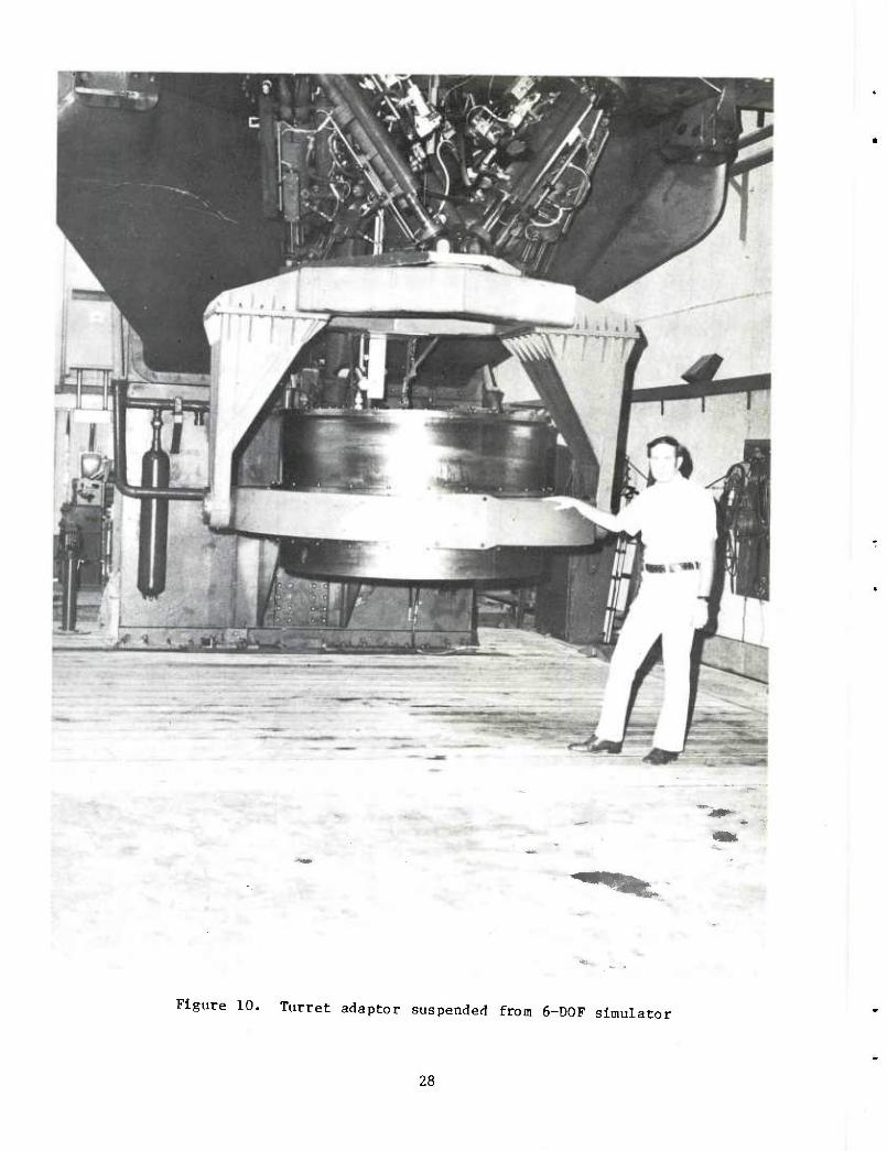
Figure 10. Turret adaptor suspended from 6-D0F simulator
28

fa o o
i
c o
•H CD
C M a
0) 4-) MH w
e o e c o
3 cr O
n
3 6C
29
DISTRIBUTION LIST
Commander U.S. Army Armament Research
and Development Command ATTN: DRDAR-SC
DRDAR-SCA (A) DRDAR-SCF (2) DRDAR-SCS (?.) DRDAR-TSE-E DRDAR-TSS (5) DRDAR-GCL
Dover, NJ 07801
Administrator Defense Technical Information Center ATTN: Accessions Division (12) Cameron Station Alexandria, VA 22314
Director U.S. Army Materiel Systems
Analysis Activity ATTN: DRXSY-MP
DRXSY-0 Aberdeen Proving Ground, MD 21005
Commander/Director Chemical Systems Laboratory U.S. Army Armament Research
and Development Command ATTN: DRDAR-CLJ-L
DRDAR-CLB-PA APG, Edgewood Area, MD 21010
Director Ballistics Research Laboratory U.S. Army Armament Research
and Development Command ATTN: DRDAR-TSB-S Aberdeen Proving Ground, MD 21005
Chief Benet Weapons Laboratory, LCWSL U.S. Army Armament Research
and Development Command ATTN: DRDAR-LCB-TL Watervliet, NY 12189
31

Commander U.S. Army Armament Materiel
Readiness Command ATTN: DRSAR-LEP-L
DRSAR-IRW Rock Island, XL 61299
Director U.S. Army TRADOC Systems
Analysis Activity ATTN: ATAA-SL White Sands Missile Range, NM 88002
Human Engineering Laboratories Liaison Office
ATTN: Len Wascher 220 7th Street Charlottesville, VA 22901
Project Manager, Cobra ATTN: DRCPM-CO-TM 4300 Goodfellow Blvd. St. Louis, MO 63120
Program Manager Advanced Attack Helicopter ATTN: DRCPM-AAH-TM 4300 Goodfellow Blvd. St. Louis, MO 63120
Department of the Army Program Manager Fighting Vehicle Systems ATTN: DRCPM-FVA
DRCPM-FVS-SE Warren, MI 48090
Commander Rock Island Arsenal ATTN: SARRI-EN
SARRI-ADL (2) Rock Island, IL 61299
Office of the Deputy Undersecretary of Defense Research and Engineering
Pentagon Room 3D1098 Washington, DC 20301
32

Commander
Headquarters, Army Materiel Development and Readiness Command
ATTN: DRCDE DRCIRD
5001 Elsenhower Avenue Alexandria, VA 22333
Commander Combined Arms Center ATTN: ATCA-COF Ft. Leavenworth, KS 66048
Commanding General Training and Doctrine Command ATTN: Library, Rldg 133 Ft. Monroe, VA 23651
Commander Army Tank Automotive Research
and Development Command ATTN: DRDTA-UL, Library Warren, MI 48090
Commandant U.S. Army Aviation Center P.O. Box 0 ATTN: USAAVNT, Library Ft. Rucker, AL 36362
Commander Harry Diamond Laboratory 2800 Powder Mill Road ATTN: DELHD-PP Adelphi, MD 20783
Commander U.S. Army Aviation Research
and Development Command P.O. Box 209 ATTN: DRDAV-EVW St. Ixmis, M0 63166
Headquarters U.S. Army Research and TechnlcalLaboratory
Ames Research Center ATTN: DAVDL-AS Moffett Field, CA 94035
33
Commander Naval Weapons Center ATTN: Code 3176, Technical Library China Lake, CA 03555
Department of the Navy Naval Air Systems Command ATTN: Code 5323D, Technical Library Washington, DC 20361
Commander Naval Surface Weapons Center ATTN: Code 022, Technical Library Dahlgren, VA 22448
Commander Air Fbrce Armament Laboratory ATTN: Technical Library Eglln Air Fbrce Base, FL 32548
34