site survey report - maryland department of public safety ... · site survey report maryland state...
TRANSCRIPT

SITE SURVEY REPORT
Maryland State Department of Corrections
Baltimore, Maryland September 29, 2005

TABLE OF CONTENTS
TABLE OF CONTENTS ..................................................................................... 2 SITE SURVEY REPORT .................................................................................... 4
CLIENT SITE INFORMATION FOR DEPARTMENT OF CORRECTIONS..................... 4 PRIMARY CONTACT FOR MD STATE DEPARTMENT OF CORRECTIONS ................. 4 WIRELESS BUILDERS INC. CONTACT INFORMATION........................................ 4
RADIO SITE SURVEY DESCRIPTION .................................................................. 5 RADIO SITE SURVEY RESULTS......................................................................... 5 DOCUMENT ATTACHMENTS ............................................................................. 5 SITE SURVEY WARRANTY................................................................................ 7
INSTALLATION SERVICE CONSIDERATIONS ................................................... 7 SITE INFORMATION ....................................................................................... 8 TECHNICIAN’S REPORT................................................................................... 9
SITE SURVEY INFORMATION:....................................................................... 9 DAY 1: ...................................................................................................... 9 SPECIFIC CHALLENGES: .............................................................................. 9 SITE SURVEY REPORT SUMMARY: ................................................................10 SITE SURVEY SUMMARY: ............................................................................10
ACCESS PORT REQUIREMENTS .......................................................................11 AP-01 ......................................................................................................11 AP-02 ......................................................................................................15 AP-03 ......................................................................................................18 AP-04 ......................................................................................................21 AP-05 ......................................................................................................24 AP-06 ......................................................................................................27 AP-07 ......................................................................................................30 AP-08 ......................................................................................................33 AP-09 ......................................................................................................36 AP-10 ......................................................................................................39 AP-11 ......................................................................................................42 AP-12 ......................................................................................................45 AP-1 ........................................................................................................48 AP-2 ........................................................................................................51
WS5100 NETWORK AND POWER CONSIDERATIONS...........................................54 CABLING DIRECTIVES ...................................................................................55
10 BASE-T ETHERNET CABLING...................................................................55 FIBER OPTIC CABLING FOR CONNECTING DISTRIBUTION FRAMES ...................56 FIBER OPTIC CABLING FOR CONNECTING WIRELESS HARDWARE ....................56
RESPONSIBILITES TO THE PREMISE WIRING COMPANY .....................................57 GENERAL RECOMMENDATIONS:......................................................................57
NETWORK INFRASTRUCTURE ......................................................................57 ACCESS PORTS .........................................................................................57 ANTENNAS ...............................................................................................57 SPECIAL CONSIDERATIONS ........................................................................57
ELECTRICAL INSTALLATION GUIDELINES .........................................................58 ATTACHMENT A - REQUIRED EQUIPMENT AND MATERIALS .................................59
SYMBOL ACCESS PORTS.............................................................................59 SYMBOL WIRELESS SWITCH .......................................................................59 POWER FOR ACCESS PORTS .......................................................................60
ATTACHMENT B - SUGGESTED EQUIPMENT AND MATERIALS...............................61

SYMBOL STANDBY WIRELESS SWITCH .........................................................61 WIRELESS NETWORK CARDS ......................................................................61
ATTACHMENT C - SUGGESTED TIME FOR INSTALLATION....................................62 PRE-CONFIGURATION PREPARATION............................................................62 CONFIGURATION.......................................................................................62 POST-CONFIGURATION ..............................................................................62
ATTACHMENT D – MOUNTING DIAGRAM FOR ACCESS PORTS..............................63 ATTACHMENT E – DIAGRAM EXAMPLE OF CABLING STRUCTURE ..........................64

2220 Boston St ♦ Baltimore, MD ♦ 21231 410-385-8532 ♦ 888-822-7887 ♦ 410-385-8559 Fax
www.WirelessBuilders.com 4
SITE SURVEY REPORT
Client Site Information for Department of Corrections 401 East Eager St Address: Baltimore, MD 21202
Primary Contact for MD State Department of Corrections Name: Kim Johnson Phone Number: 410-585-3804 Email Address: [email protected]
401 East Eager St. Office Address: Baltimore, Maryland 21202
Wireless Builders Inc. Contact Information Sales Associate: Becky Bush Phone Number: 888-860-7226 x Email Address: beckyb@Wireless Builders.com System Engineer: Michael Calhoun Phone Number: 888-860-7226 x115 Email Address: michaelc@Wireless Builders.com VP of Professional Services: Richard Schrock Phone Number: 888-860-7226 x108 Email Address: richs@Wireless Builders.com

2220 Boston St ♦ Baltimore, MD ♦ 21231 410-385-8532 ♦ 888-822-7887 ♦ 410-385-8559 Fax
www.WirelessBuilders.com 5
RADIO SITE SURVEY DESCRIPTION
The radio site survey is a process by which test data is collected and used to determine hardware requirements needed to achieve a RELIABLE RF PROPAGATION. Data is collected by establishing two-way radio communication via a stationary and mobile unit at various points within a facility at 2.4 GHz utilizing the Direct Sequence spectrum standard. To assess RF communication Wireless Builders Inc. employs a Laptop with an 802.11b card and a Symbol AP4131 Access Port with two high-gain, dipole antennas. Testing is performed with the Symbol Mobile Companion utility. In Survey Mode, This application constantly transmits, examines, and echoes data packets between the two units. The following are the parameters configured on the AP and terminal. Bit Rate: 2-11 Mb/s Message Size: 512 Bytes Packet Size: continuous pings The results are continuously displayed on the laptop to provide instantaneous feedback. The laptop is moved throughout the site area and results are interpreted to determine a Reliable RF Propagation Zone.
RADIO SITE SURVEY RESULTS
A Reliable RF Propagation Zone is defined as an area where the RF signal ranges from -60dBm to -30dBm (40%-100% signal strength). Along with a strong signal, a Reliable RF propagation Zone must also provide reliable data transfer. Reliable RF data transfer is determined by comparing the amount of lost packets to the amount of packets transferred. Data transfer is reliable if the packet loss does not exceed 5% of the packets transferred. To achieve a Reliable RF Propagation Zone for the wireless data collection units in Baltimore, Maryland facility of MD State Department of Corrections, Fourteen (14) Access Ports should be installed in the warehouse. Those access ports should be connected to One (1) Wireless Switch with 12 licenses installed.
DOCUMENT ATTACHMENTS
Attachment A Required Equipment and Materials. Attachment B Suggested Equipment and Materials. Attachment C Suggested Time for Access Port Installation Attachment D Mounting Diagram for Access Ports.

2220 Boston St ♦ Baltimore, MD ♦ 21231 410-385-8532 ♦ 888-822-7887 ♦ 410-385-8559 Fax
www.WirelessBuilders.com 6
Attachment E Diagram Example of Cabling Structure.

2220 Boston St ♦ Baltimore, MD ♦ 21231 410-385-8532 ♦ 888-822-7887 ♦ 410-385-8559 Fax
www.WirelessBuilders.com 7
SITE SURVEY WARRANTY
On September 29, 2005, a site survey was performed to provide 100% RF coverage in the areas designated for MD State Department of Correction’s Baltimore, Maryland facility. These results are certified for ninety days (90) from the date the survey is performed. The warranty further assumes that there are no changes to the facility’s structure, variable parameters within the building that may modify the RF propagation, or the addition of other RF devices that may interfere with the installed RF equipment. Changes to the facility’s structure, or other parameters may require the need for an additional survey at the cost of the customer. Environmental changes can affect system requirements creating additional costs in labor and materials to the customer. This warranty is limited to RF coverage and does not provide any explicit or implied guarantee relating to other network design parameters; such as but not limited to: optimum network speed, data throughput, fault tolerance, redundancy, etc.
Installation Service Considerations It always recommended that the company which performs the site survey, for a specific customer site, always performs the wireless hardware installation. This process is recommended to allow the customer a seamless wireless integration process with a company that is already familiarized with the customer’s site. Although a company may employ individuals with enough expertise to implement an RF system, these individuals cannot guarantee their work with a strong manufacture relationship. Wireless Builders, Inc. is a value added reseller providing a solution to MD State Department of Corrections. The intended purpose of a Value Added Reseller is to not only provide hardware, but to provide the highest level of service and support available. The above warranty only guarantees the quality of work for the Site Survey. This warranty covers any coverage-related with the wireless network (as listed in the warranty). If the decision is made to install the wireless hardware without using Wireless Builders, Inc. installation services, Wireless Builders, Inc. cannot provide any support outside of the guarantee of the current Site Survey warranty; however, utilizing installation services will provide full support for all wireless hardware configured and installed by Wireless Builders, Inc.

2220 Boston St ♦ Baltimore, MD ♦ 21231 410-385-8532 ♦ 888-822-7887 ♦ 410-385-8559 Fax
www.WirelessBuilders.com 8
Any questions related to the warranty in this document and the scope of service provided by Wireless Builders, Inc. should be directed to your Sales Representatives
SITE INFORMATION
Layout Square footage of Facility: Approx 100,000 sq feet Square footage of Coverage: Approx 100,000 sq feet Number of Floors: 2 Number of Buildings: 1 Ceiling Height: 10 feet Ceiling Material: Concrete Floor Material: Concrete Network Current Topology Ethernet Data/Network Environment Emulation Special Facility Considerations Minimum Temperature 65 degrees Maximum Temperature 90 degrees Intrinsically Safe? No Eye Protection? No Ear Protection? No Foot Protection? No Other:

2220 Boston St ♦ Baltimore, MD ♦ 21231 410-385-8532 ♦ 888-822-7887 ♦ 410-385-8559 Fax
www.WirelessBuilders.com 9
TECHNICIAN’S REPORT
Site Survey Information: Totals Days spent onsite: 1 Primary Site Contact: Kim Johnson
Heath Willard Additional Site Contact(s):
Day 1:
Date: September 29, 2005 Time of Arrival: 9:00 am Time of Departure: 4:00 pm Daily Summary: Met with Kim and given a tour of the area of the
facility that would require wireless coverage. The system need to be redundant with backup coverage supplied by Access Ports.
Specific Challenges:
Specific problems encountered during the Site Survey:
The survey was of the central booking facility of Baltimore Detention Center.
Specific problems that could be encountered at the time of installation:
Access to the facility
Man-Lift Requirement: No lift will be required.

2220 Boston St ♦ Baltimore, MD ♦ 21231 410-385-8532 ♦ 888-822-7887 ♦ 410-385-8559 Fax
www.WirelessBuilders.com 10
Site Survey Report Summary:
Date Started: September 29, 2005 Time Started: 9:00 AM Date Completed: September 29, 2005 Time Completed: 4:00 PM
Site Survey Summary: Time spent Onsite: 8 Hours Time spent for Documentation: 4 Hours Total Time for Services: 12 Hours

2220 Boston St ♦ Baltimore, MD ♦ 21231 410-385-8532 ♦ 888-822-7887 ♦ 410-385-8559 Fax
www.WirelessBuilders.com 11
ACCESS PORT REQUIREMENTS
AP-01 Access Port Information
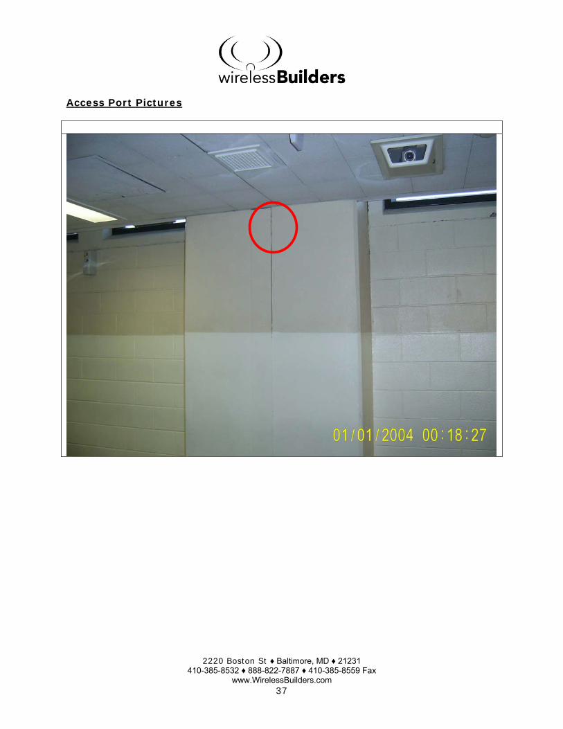
Access Port Model Number: Symbol AP300Access Port Location: The Access will be located in the Police area of the
facility. Coverage Area: See the coverage drawing for a graphic
representation of the area that the Access Port will cover.
Mounting Height: 9 feet Outdoor Requirements: None Access Port Power: 50 percent Diversity Setting: Off RF Channel Setting: 6Power Setting: 50mWData Cable Type: CAT5ENearest Network Connection: Data Closet in hall Estimated Cable Length: <100 feet
- Picture on Next Page -

2220 Boston St ♦ Baltimore, MD ♦ 21231 410-385-8532 ♦ 888-822-7887 ♦ 410-385-8559 Fax
www.WirelessBuilders.com 12

2220 Boston St ♦ Baltimore, MD ♦ 21231 410-385-8532 ♦ 888-822-7887 ♦ 410-385-8559 Fax
www.WirelessBuilders.com 13
Access Port Pictures
Police Area of the facility

2220 Boston St ♦ Baltimore, MD ♦ 21231 410-385-8532 ♦ 888-822-7887 ♦ 410-385-8559 Fax
www.WirelessBuilders.com 14
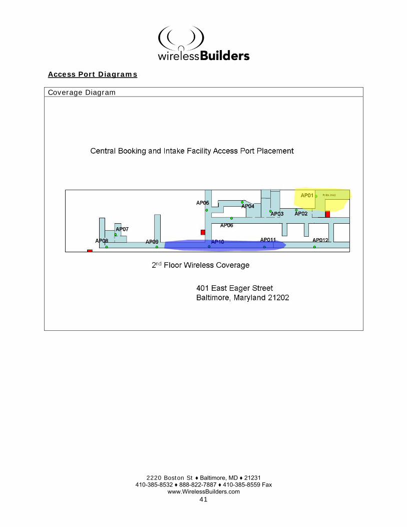
Access Port Diagrams
Coverage Diagram

2220 Boston St ♦ Baltimore, MD ♦ 21231 410-385-8532 ♦ 888-822-7887 ♦ 410-385-8559 Fax
www.WirelessBuilders.com 15
AP-02 Access Port Information
Access Port Model Number: Symbol AP300 Access Port Location: The Access will be located in a hall of the facility.
Coverage Area: See the coverage drawing for a graphic representation of the area that the Access Port will cover.
Mounting Height: 9 feet Outdoor Requirements: None Access Port Power: 50 percent Diversity Setting: Off RF Channel Setting: 1 Power Setting: 50mW Data Cable Type: CAT5E Nearest Network Connection: Data Closet in hall Estimated Cable Length: <100 feet
- Picture on Next Page -

2220 Boston St ♦ Baltimore, MD ♦ 21231 410-385-8532 ♦ 888-822-7887 ♦ 410-385-8559 Fax
www.WirelessBuilders.com 16
Access Port Pictures

2220 Boston St ♦ Baltimore, MD ♦ 21231 410-385-8532 ♦ 888-822-7887 ♦ 410-385-8559 Fax
www.WirelessBuilders.com 17
Access Port Diagrams
Coverage Diagram

2220 Boston St ♦ Baltimore, MD ♦ 21231 410-385-8532 ♦ 888-822-7887 ♦ 410-385-8559 Fax
www.WirelessBuilders.com 18
AP-03 Access Port Information
Access Port Model Number: Symbol AP300 Access Port Location: This Access Point will be located in the area of the
facility where pictures and fingerprints are taken. Coverage Area: See the coverage drawing for a graphic
representation of the area that the Access Port will cover.
Mounting Height: 9 feet Outdoor Requirements: None Access Port Power: 50 percent Diversity Setting: Off RF Channel Setting: 11 Power Setting: 50mW Data Cable Type: CAT5E Nearest Network Connection: Data Closet in hall Estimated Cable Length: <100 feet
- Picture on Next Page -

2220 Boston St ♦ Baltimore, MD ♦ 21231 410-385-8532 ♦ 888-822-7887 ♦ 410-385-8559 Fax
www.WirelessBuilders.com 19
Access Port Pictures

2220 Boston St ♦ Baltimore, MD ♦ 21231 410-385-8532 ♦ 888-822-7887 ♦ 410-385-8559 Fax
www.WirelessBuilders.com 20
Access Port Diagrams
Coverage Diagram

2220 Boston St ♦ Baltimore, MD ♦ 21231 410-385-8532 ♦ 888-822-7887 ♦ 410-385-8559 Fax
www.WirelessBuilders.com 21
AP-04 Access Port Information
Access Port Model Number: Symbol AP300 Access Port Location: This Access Point will be located in the area of the
facility where pictures and fingerprints are taken. Coverage Area: See the coverage drawing for a graphic
representation of the area that the Access Port will cover.
Mounting Height: 9 feet Outdoor Requirements: None Access Port Power: 50 percent Diversity Setting: Off RF Channel Setting: 11 Power Setting: 50mW Data Cable Type: CAT5E Nearest Network Connection: Data Closet in hall Estimated Cable Length: <100 feet
- Picture on Next Page -

2220 Boston St ♦ Baltimore, MD ♦ 21231 410-385-8532 ♦ 888-822-7887 ♦ 410-385-8559 Fax
www.WirelessBuilders.com 22
Access Port Pictures

2220 Boston St ♦ Baltimore, MD ♦ 21231 410-385-8532 ♦ 888-822-7887 ♦ 410-385-8559 Fax
www.WirelessBuilders.com 23
Access Port Diagrams
Coverage Diagram

2220 Boston St ♦ Baltimore, MD ♦ 21231 410-385-8532 ♦ 888-822-7887 ♦ 410-385-8559 Fax
www.WirelessBuilders.com 24
AP-05 Access Port Information
Access Port Model Number: Symbol AP300 Access Port Location: This Access Point will be located in the area of the
facility where the women are located. Coverage Area: See the coverage drawing for a graphic
representation of the area that the Access Port will cover.
Mounting Height: 9 feet Outdoor Requirements: None Access Port Power: 50 percent Diversity Setting: Off RF Channel Setting: 1 Power Setting: 50mW Data Cable Type: CAT5E Nearest Network Connection: Data Closet in hall Estimated Cable Length: <200 feet
- Picture on Next Page -
2220 Boston St ♦ Baltimore, MD ♦ 21231 410-385-8532 ♦ 888-822-7887 ♦ 410-385-8559 Fax
www.WirelessBuilders.com 25
Access Port Pictures

2220 Boston St ♦ Baltimore, MD ♦ 21231 410-385-8532 ♦ 888-822-7887 ♦ 410-385-8559 Fax
www.WirelessBuilders.com 26
Access Port Diagrams
Coverage Diagram

2220 Boston St ♦ Baltimore, MD ♦ 21231 410-385-8532 ♦ 888-822-7887 ♦ 410-385-8559 Fax
www.WirelessBuilders.com 27
AP-06 Access Port Information
Access Port Model Number: Symbol AP300 Access Port Location: This Access Point will be located in the hall of the
facility. Coverage Area: See the coverage drawing for a graphic
representation of the area that the Access Port will cover.
Mounting Height: 9 feet Outdoor Requirements: None Access Port Power: 50 percent Diversity Setting: Off RF Channel Setting: 6 Power Setting: 50mW Data Cable Type: CAT5E Nearest Network Connection: Data Closet in hall Estimated Cable Length: <200 feet
- Picture on Next Page -

2220 Boston St ♦ Baltimore, MD ♦ 21231 410-385-8532 ♦ 888-822-7887 ♦ 410-385-8559 Fax
www.WirelessBuilders.com 28
Access Port Pictures

2220 Boston St ♦ Baltimore, MD ♦ 21231 410-385-8532 ♦ 888-822-7887 ♦ 410-385-8559 Fax
www.WirelessBuilders.com 29
Access Port Diagrams
Coverage Diagram
2220 Boston St ♦ Baltimore, MD ♦ 21231 410-385-8532 ♦ 888-822-7887 ♦ 410-385-8559 Fax
www.WirelessBuilders.com 30
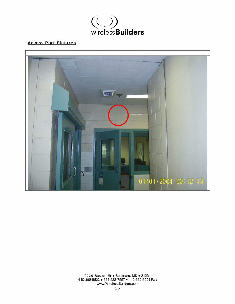
AP-07 Access Port Information
Access Port Model Number: Symbol AP300 Access Port Location: This Access Point will be located in an office of the
facility. Coverage Area: See the coverage drawing for a graphic
representation of the area that the Access Port will cover.
Mounting Height: 9 feet Outdoor Requirements: None Access Port Power: 50 percent Diversity Setting: Off RF Channel Setting: 11 Power Setting: 50mW Data Cable Type: CAT5E Nearest Network Connection: Data Closet in hall Estimated Cable Length: <200 feet
- Picture on Next Page -
2220 Boston St ♦ Baltimore, MD ♦ 21231 410-385-8532 ♦ 888-822-7887 ♦ 410-385-8559 Fax
www.WirelessBuilders.com 31
Access Port Pictures

2220 Boston St ♦ Baltimore, MD ♦ 21231 410-385-8532 ♦ 888-822-7887 ♦ 410-385-8559 Fax
www.WirelessBuilders.com 32
Access Port Diagrams
Coverage Diagram
2220 Boston St ♦ Baltimore, MD ♦ 21231 410-385-8532 ♦ 888-822-7887 ♦ 410-385-8559 Fax
www.WirelessBuilders.com 33
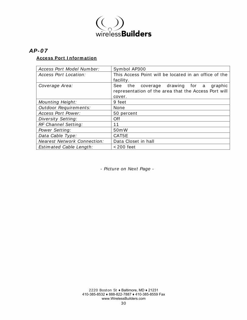
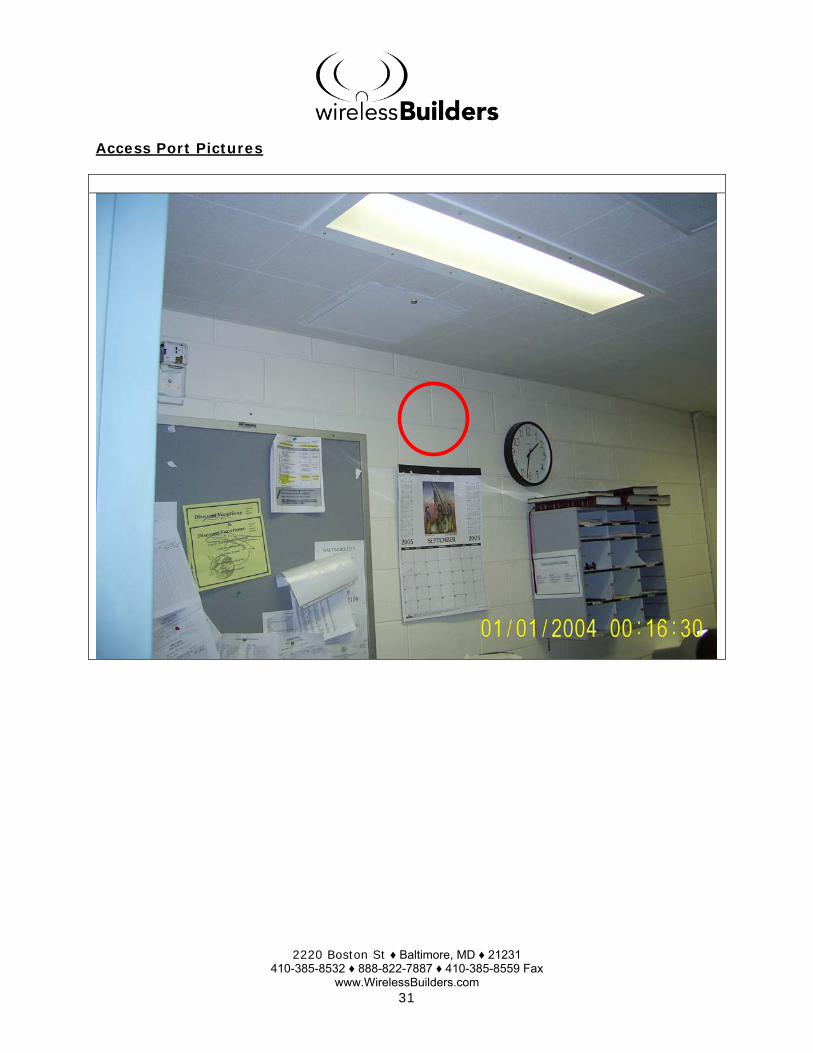
AP-08 Access Port Information
Access Port Model Number: Symbol AP300 Access Port Location: This Access Point will be located in the hall of the
facility. Coverage Area: See the coverage drawing for a graphic
representation of the area that the Access Port will cover.
Mounting Height: 9 feet Outdoor Requirements: None Access Port Power: 50 percent Diversity Setting: Off RF Channel Setting: 1 Power Setting: 50mW Data Cable Type: CAT5E Nearest Network Connection: Data Closet in hall Estimated Cable Length: <200 feet
- Picture on Next Page -

2220 Boston St ♦ Baltimore, MD ♦ 21231 410-385-8532 ♦ 888-822-7887 ♦ 410-385-8559 Fax
www.WirelessBuilders.com 34
Access Port Pictures

2220 Boston St ♦ Baltimore, MD ♦ 21231 410-385-8532 ♦ 888-822-7887 ♦ 410-385-8559 Fax
www.WirelessBuilders.com 35
Access Port Diagrams
Coverage Diagram

2220 Boston St ♦ Baltimore, MD ♦ 21231 410-385-8532 ♦ 888-822-7887 ♦ 410-385-8559 Fax
www.WirelessBuilders.com 36
AP-09 Access Port Information
Access Port Model Number: Symbol AP300 Access Port Location: This Access Point will be located in the hall of the
facility. Coverage Area: See the coverage drawing for a graphic
representation of the area that the Access Port will cover.
Mounting Height: 9 feet Outdoor Requirements: None Access Port Power: 50 percent Diversity Setting: Off RF Channel Setting: 11 Power Setting: 50mW Data Cable Type: CAT5E Nearest Network Connection: Data Closet in hall Estimated Cable Length: <200 feet
- Picture on Next Page -
2220 Boston St ♦ Baltimore, MD ♦ 21231 410-385-8532 ♦ 888-822-7887 ♦ 410-385-8559 Fax
www.WirelessBuilders.com 37
Access Port Pictures

2220 Boston St ♦ Baltimore, MD ♦ 21231 410-385-8532 ♦ 888-822-7887 ♦ 410-385-8559 Fax
www.WirelessBuilders.com 38
Access Port Diagrams
Coverage Diagram

2220 Boston St ♦ Baltimore, MD ♦ 21231 410-385-8532 ♦ 888-822-7887 ♦ 410-385-8559 Fax
www.WirelessBuilders.com 39
AP-10 Access Port Information
Access Port Model Number: Symbol AP300 Access Port Location: This Access Point will be located in the hall of the
facility. Coverage Area: See the coverage drawing for a graphic
representation of the area that the Access Port will cover.
Mounting Height: 9 feet Outdoor Requirements: None Access Port Power: 50 percent Diversity Setting: Off RF Channel Setting: 1 Power Setting: 50mW Data Cable Type: CAT5E Nearest Network Connection: Data Closet in hall Estimated Cable Length: <200 feet
- Picture on Next Page -

2220 Boston St ♦ Baltimore, MD ♦ 21231 410-385-8532 ♦ 888-822-7887 ♦ 410-385-8559 Fax
www.WirelessBuilders.com 40
Access Port Pictures
2220 Boston St ♦ Baltimore, MD ♦ 21231 410-385-8532 ♦ 888-822-7887 ♦ 410-385-8559 Fax
www.WirelessBuilders.com 41
Access Port Diagrams
Coverage Diagram

2220 Boston St ♦ Baltimore, MD ♦ 21231 410-385-8532 ♦ 888-822-7887 ♦ 410-385-8559 Fax
www.WirelessBuilders.com 42
AP-11 Access Port Information
Access Port Model Number: Symbol AP300 Access Port Location: This Access Point will be located in the hall of the
facility. Coverage Area: See the coverage drawing for a graphic
representation of the area that the Access Port will cover.
Mounting Height: 9 feet Outdoor Requirements: None Access Port Power: 50 percent Diversity Setting: Off RF Channel Setting: 6 Power Setting: 50mW Data Cable Type: CAT5E Nearest Network Connection: Data Closet in hall Estimated Cable Length: <200 feet
- Picture on Next Page -

2220 Boston St ♦ Baltimore, MD ♦ 21231 410-385-8532 ♦ 888-822-7887 ♦ 410-385-8559 Fax
www.WirelessBuilders.com 43
Access Port Pictures

2220 Boston St ♦ Baltimore, MD ♦ 21231 410-385-8532 ♦ 888-822-7887 ♦ 410-385-8559 Fax
www.WirelessBuilders.com 44
Access Port Diagrams
Coverage Diagram

2220 Boston St ♦ Baltimore, MD ♦ 21231 410-385-8532 ♦ 888-822-7887 ♦ 410-385-8559 Fax
www.WirelessBuilders.com 45
AP-12 Access Port Information
Access Port Model Number: Symbol AP300 Access Port Location: This Access Point will be located in the hall of the
facility. Coverage Area: See the coverage drawing for a graphic
representation of the area that the Access Port will cover.
Mounting Height: 9 feet Outdoor Requirements: None Access Port Power: 50 percent Diversity Setting: Off RF Channel Setting: 11 Power Setting: 50mW Data Cable Type: CAT5E Nearest Network Connection: Data Closet in hall Estimated Cable Length: <200 feet
- Picture on Next Page -

2220 Boston St ♦ Baltimore, MD ♦ 21231 410-385-8532 ♦ 888-822-7887 ♦ 410-385-8559 Fax
www.WirelessBuilders.com 46
Access Port Pictures

2220 Boston St ♦ Baltimore, MD ♦ 21231 410-385-8532 ♦ 888-822-7887 ♦ 410-385-8559 Fax
www.WirelessBuilders.com 47
Access Port Diagrams
Coverage Diagram

2220 Boston St ♦ Baltimore, MD ♦ 21231 410-385-8532 ♦ 888-822-7887 ♦ 410-385-8559 Fax
www.WirelessBuilders.com 48
AP-1 Access Port Information
Access Port Model Number: Symbol AP300 Access Port Location: This Access Point will be located in the IT office
area. Coverage Area: See the coverage drawing for a graphic
representation of the area that the Access Port will cover.
Mounting Height: 9 feet Outdoor Requirements: None Access Port Power: 50 percent Diversity Setting: Off RF Channel Setting: 1 Power Setting: 50mW Data Cable Type: CAT5E Nearest Network Connection: Data Closet in hall Estimated Cable Length: <200 feet
- Picture on Next Page -

2220 Boston St ♦ Baltimore, MD ♦ 21231 410-385-8532 ♦ 888-822-7887 ♦ 410-385-8559 Fax
www.WirelessBuilders.com 49
Access Port Pictures

2220 Boston St ♦ Baltimore, MD ♦ 21231 410-385-8532 ♦ 888-822-7887 ♦ 410-385-8559 Fax
www.WirelessBuilders.com 50
Access Port Diagrams
Coverage Diagram

2220 Boston St ♦ Baltimore, MD ♦ 21231 410-385-8532 ♦ 888-822-7887 ♦ 410-385-8559 Fax
www.WirelessBuilders.com 51
AP-2 Access Port Information
Access Port Model Number: Symbol AP300 Access Port Location: This Access Point will be located in the area where
the Personal belongings are stored. Coverage Area: See the coverage drawing for a graphic
representation of the area that the Access Port will cover.
Mounting Height: 9 feet Outdoor Requirements: None Access Port Power: 50 percent Diversity Setting: Off RF Channel Setting: 6 Power Setting: 50mW Data Cable Type: CAT5E Nearest Network Connection: Data Closet in hall Estimated Cable Length: <200 feet
- Picture on Next Page -

2220 Boston St ♦ Baltimore, MD ♦ 21231 410-385-8532 ♦ 888-822-7887 ♦ 410-385-8559 Fax
www.WirelessBuilders.com 52
Access Port Pictures

2220 Boston St ♦ Baltimore, MD ♦ 21231 410-385-8532 ♦ 888-822-7887 ♦ 410-385-8559 Fax
www.WirelessBuilders.com 53
Access Port Diagrams
Coverage Diagram

2220 Boston St ♦ Baltimore, MD ♦ 21231 410-385-8532 ♦ 888-822-7887 ♦ 410-385-8559 Fax
www.WirelessBuilders.com 54
WS5100 NETWORK AND POWER CONSIDERATIONS
This page presents three ways to provide Ethernet and electrical power to Symbol WS5100 high rate Access Ports. The Access Ports require power over Ethernet. As a result, it is really not efficient to use the AC Power option. AC Power/CAT5 cabling – This option incorporates an AC outlet and a CAT5 Ethernet cabling run to each AP location. The AC outlets provide power to the power over Ethernet port and the port then provides power to the AP through CAT5 cabling. Generally, the AC outlet should be within 10 feet of the AP mounting location. This option is not recommended as it would make more sense to have the POE devices reside at the IDF/MDF for easier access. DC Power/CAT5 cabling – This option sends DC power through the standard CAT5 Ethernet cable. The power is provided by a power supply residing at the origin of the Ethernet cable and passes the electricity through the BIAST Power over Ethernet hub, which in turn passes the electricity through the Ethernet cable itself. This is a convenient solution if the facility does not have existing AC outlets near the AP locations. DC Power/Fiber cabling – This option is used when an AP is being installed to a location that’s distance is greater then 100 meters (324 feet). There are two approaches of running Fiber:
a. The first technique is to run Fiber cabling to each AP location from a central hub. This would require two media converters (one at the point of origin, the other at the destination) to convert the fiber media to Ethernet. AC outlets will need to be in place at each AP location to provide power. b. The second approach is to run a home run Fiber cable to a switch or hub and then run Ethernet from this location to each Access Port. Then power can be provided either by AC outlets or the DC Power option as described above.
2220 Boston St ♦ Baltimore, MD ♦ 21231 410-385-8532 ♦ 888-822-7887 ♦ 410-385-8559 Fax
www.WirelessBuilders.com 55
CABLING DIRECTIVES
The following three pages should be printed out and given to the premise wiring specialist before the wiring installation is performed.
Wireless Builders, Inc. is not responsible for the integrity of the Network or the impact of additional expansion. Failure to conform to these directives may result in additional costs which may be passed on to MD State Department of Corrections.
10 Base-T Ethernet Cabling • Category 5/5e/6 UTP (Unshielded Twisted Pair) cabling will be installed from
the nearest Ethernet switches to each individual Access Port. • All 10 Base-T cable runs will be a maximum length of 100 meters (324 feet). • Each 10 Base-T cable run will be terminated with a RJ45 jack at the Access
Port end and will be connected to a patch panel at the Ethernet switch end. • All patch panel ports should be labeled as “APxx” (where xx is the number or
letter of the Access Port terminated at the port). The included drawings and pictures should be referenced in this naming process. Additionally, tags at each Access Port location were also labeled as “APxx”
• Cabling should be run at the warehouse ceiling level. • Cabling will have a minimum of 3-foot clearance from existing AC power
cables. Do not install data cable runs in parallel with existing AC conduit. • Patch Cable – The wiring specialist is responsible for providing patch cabling.
Quantities are listed below a. AC Power – Two lengths (of at least 3ft) should be left per Access Port b. Power over Ethernet – Three lengths (of at least 3ft) should be left per
Access Port • Toning each wire run is not sufficient. Each wire run must have a 4 pair test
performed. If possible, a configured Access Port should be used to test the wire run. While plugged in, another employee should ping the Access Port for connectivity.
• FOR ALL IDF and MDF structures: Sufficient electrical outlets must be left for power of Ethernet hardware.
a. For POE hubs – One outlet per hub b. For individual POE devices – One outlet per Access Port (terminated at
that specific location) • Conform to IEEE standards for the type of cabling to be installed. • CABLING MUST BE COMPLETED BEFORE THE DATE OF WIRELESS
HARDWARE INSTALLATION

2220 Boston St ♦ Baltimore, MD ♦ 21231 410-385-8532 ♦ 888-822-7887 ♦ 410-385-8559 Fax
www.WirelessBuilders.com 56
Fiber Optic Cabling for connecting distribution frames • This Infrastructure does not directly affect the wireless system in terms of
direct connection to the hardware. Directives for this infrastructure are left up to MD State Department of Corrections’ preference.
Fiber Optic Cabling for connecting wireless hardware • All Fiber runs must be tested and certified by the wiring specialist. A
certification report, documenting test results, should be made available to Wireless Builders, Inc.
• All Fiber runs must be terminated with “ST” connector types. • All Fiber runs should be multi-mode, .50 micron in size. • Media Converters on both ends must be tested for link and activity. • Patch Cables WILL be connected to Media Converters at each Access Port
location. • Each termination at the Fiber patch panel must be labeled as “APxx” (where
xx is the given letter or number of the Access Port location). The Drawings and Pictures in this document should be referenced in assisting in this process.
• Each Media Converter at the distribution frame must be connected to the fiber patch panel and Ethernet switch.
• The entire Fiber backbone (including Media Converters) will be properly crossed over and configured so that Ethernet communication is available as soon as the wireless devices are connected.
• There must be enough spare Media Converters available to assume for a 10% hardware failure of ALL Media Converters being used.
One of the Wiring Specialists should be onsite for the second day of wireless installation (the second day is commonly when the hardware is connected to the wired infrastructure). This is to allow for any troubleshooting with the wired infrastructure. If Wireless Builders, Inc. must perform any wired network troubleshooting, this will be considered an additional service to the wireless installation and this cost will be passed on.

2220 Boston St ♦ Baltimore, MD ♦ 21231 410-385-8532 ♦ 888-822-7887 ♦ 410-385-8559 Fax
www.WirelessBuilders.com 57
WIRELESS BUILDERS, INC. – RESPONSIBILITES TO THE PREMISE WIRING COMPANY
• Provide the wiring company with any information needed to perform their installation (most of which is contained in this document)
• Provide any needed graphics to assist in labeling and locating recommended installation locations.
• Provide any needed clarification to the directives listed in this document. • Test all wireless hardware at ground level to ensure functionality before
installation in the warehouse ceiling (to the satisfaction of MD State Department of Corrections).
GENERAL RECOMMENDATIONS:
Network Infrastructure The WS5100 system is best used with a physical or logical separation of the wireless and wired networks. It is highly recommended that a separate VLAN is created for the wireless network. This will allow the WS5100 to better manage the wireless traffic. Additionally, if multiple VLAN’s are going to be used, an 802.1Q trunk port must be created for each WS5100 device.
Access Ports Do not mount any Access Port or antenna higher than the onsite forklift with the safety cage will reach. It is MD State Department of Corrections’ responsibility to bring Access Port mounted above 10 feet down to the floor level for servicing.
Antennas Maintain maximum clearance around antenna.
Special Considerations To aid in locating the RF system, it is suggested that a copy of this report be kept in the computer room and made available to any service technicians or electricians, which may be doing work in your facility. All wiring should be completed and tested by the time of scheduled installation. If wiring is incomplete or is being installed at the time of scheduled RF installation, the RF installation could be severely delayed.

2220 Boston St ♦ Baltimore, MD ♦ 21231 410-385-8532 ♦ 888-822-7887 ♦ 410-385-8559 Fax
www.WirelessBuilders.com 58
ELECTRICAL INSTALLATION GUIDELINES
Symbol Technologies equipment is subject to degradation due to some commonly inherent or random electrical problems or disturbances. This report in no way implies or warrants that electrical problems will not present themselves at some future time. These electrical installation alternatives are listed from most desirable to least desirable. In all cases, the power to the Access Ports must be un-switched and available 24 hours per day. It is recommended that the power never be provided from an Energy Management System.
1. Isolated ground circuit with an on-line uninterruptible power supply (UPS), which will also act as a filter and surge suppresser.
2. Isolated ground circuit with a surge suppresser. 3. Dedicated circuit with a UPS. 4. Dedicated circuit with a surge suppresser. 5. Non-dedicated circuit with a UPS. 6. Non-dedicated circuit with a surge suppresser.
Items 1 through 4 are recommended for an NCU (Network Controller Unit) if present in your configuration. Deviation from one of these options can cause loss of data being transmitted. Configurations 5 and 6 must be considered suspect at best. Due to the nature of a non-dedicated circuit, which has open receptacles, the load and type of use cannot be predicted at the time of installation. While the current draw of the Access Ports is minimal, other devices on the circuit can affect them. If it is absolutely necessary to have a non-dedicated circuit, we recommend • No devices should be hard wired into the circuit. • No devices with components intended to produce heat should ever be used on
the circuit, e.g., space heaters, laser printers, heat guns, soldering irons, photocopiers.
• No devices prone to causing sudden sharp surges in the power line or which contain medium or large motors should be used on the circuit, e.g., electric staplers, refrigerators, floor cleaning equipment, air conditioners, fans, drills. Some acceptable devices are: personal computers with few add-in cards and devices, paper tape calculators.
• No single device drawing more than 20% of the rated value of the circuit should be used.
• No combination of devices drawing more than 60% of the rated value of the circuit should be used.

2220 Boston St ♦ Baltimore, MD ♦ 21231 410-385-8532 ♦ 888-822-7887 ♦ 410-385-8559 Fax
www.WirelessBuilders.com 59
ATTACHMENT A - REQUIRED EQUIPMENT AND MATERIALS
Symbol Access Ports Description Part Number Qty AP300, 802.11G Access Port, Internal Antenna Connections
WSAP-5110-050-WW 14
Symbol Wireless Switch Description Part Number Qty
WS5100 Wireless Switch, 18 AP licenses
WS-5100-R200-18-WW
1

2220 Boston St ♦ Baltimore, MD ♦ 21231 410-385-8532 ♦ 888-822-7887 ♦ 410-385-8559 Fax
www.WirelessBuilders.com 60
Power for Access Ports Description Part Number Qty BIAS-T Power through Ethernet Hub, Single Port
AP-PBIAS-T-1P-AF 14
US Line Cord 23844-00-00 14

2220 Boston St ♦ Baltimore, MD ♦ 21231 410-385-8532 ♦ 888-822-7887 ♦ 410-385-8559 Fax
www.WirelessBuilders.com 61
ATTACHMENT B - SUGGESTED EQUIPMENT AND MATERIALS
Symbol Standby Wireless Switch Description Part Number Qty
WS5100 Wireless Switch, Standby/Backup license WS-5100-R200-RS-WW
1
Wireless Network Cards Description Part Number Qty PC Card WLAN adapter, 11 Mbps (PCMCIA) LA-5030-102-WW 1

2220 Boston St ♦ Baltimore, MD ♦ 21231 410-385-8532 ♦ 888-822-7887 ♦ 410-385-8559 Fax
www.WirelessBuilders.com 62
ATTACHMENT C - SUGGESTED TIME FOR INSTALLATION
This quote assumes the following: • Mounting situations have not drastically changed so that additional
equipment is not required • Work will not have to be delayed to accommodate MD State Department of
Corrections’ normal working schedule • One technician will perform the entire installation • All requested configuration information for the wireless hardware is readily
available when the technician arrives
Pre-Configuration Preparation Description Total Time for task (hrs) Unpack, Verify, and Stage equipment and hardware 4
Configuration Description Total Time for task (hrs) Configure Access Ports 4
Post-Configuration Description Total Time for task (hrs) Mounting Preparation (brackets, hardware, etc.) 4 AP Mounting 16 hours Antenna Mounting 4 Site Commissioning 4 Wireless Hardware – Basic Training 4 Documentation – Installation Report 4
Total Installation Time (hrs) 44
2220 Boston St ♦ Baltimore, MD ♦ 21231 410-385-8532 ♦ 888-822-7887 ♦ 410-385-8559 Fax
www.WirelessBuilders.com 63
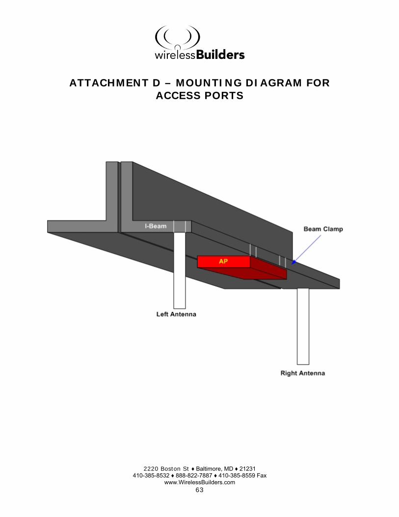
ATTACHMENT D – MOUNTING DIAGRAM FOR ACCESS PORTS

2220 Boston St ♦ Baltimore, MD ♦ 21231 410-385-8532 ♦ 888-822-7887 ♦ 410-385-8559 Fax
www.WirelessBuilders.com 64
ATTACHMENT E – DIAGRAM EXAMPLE OF CABLING STRUCTURE