site recovery manager administration guide - vmware.com · site recovery manager administration...
TRANSCRIPT
Administration GuideSite Recovery Manager 1.0 Update 1
VMware, Inc.3401 Hillview Ave.Palo Alto, CA 94304www.vmware.com
2 VMware, Inc.
Site Recovery Manager Administration Guide
You can find the most up-to-date technical documentation on the VMware Web site at:
http://www.vmware.com/support/
The VMware Web site also provides the latest product updates.
If you have comments about this documentation, submit your feedback to:
© 2008 VMware, Inc. All rights reserved. Protected by one or more U.S. Patent Nos. 6,397,242, 6,496,847, 6,704,925, 6,711,672, 6,725,289, 6,735,601, 6,785,886, 6,789,156, 6,795,966, 6,880,022, 6,944,699, 6,961,806, 6,961,941, 7,069,413, 7,082,598, 7,089,377, 7,111,086, 7,111,145, 7,117,481, 7,149,843, 7,155,558, 7,222,221, 7,260,815, 7,260,820, 7,269,683, 7,275,136, 7,277,998, 7,277,999, 7,278,030, 7,281,102, 7,290,253, 7,356,679, 7,409,487, 7,412,492, 7,412,702, 7,424,710, 7,428,636, 7,433,951, 7,434,002, and 7,447,854; patents pending.
VMware, the VMware “boxes” logo and design, Virtual SMP, and VMotion are registered trademarks or trademarks of VMware, Inc. in the United States and/or other jurisdictions. All other marks and names mentioned herein may be trademarks of their respective companies.
Site Recovery Manager Administration GuideItem: EN-000096-00
VMware, Inc. 3
Contents
About This Book 7
1 Overview of Site Recovery Manager 9VMware Infrastructure Supports Site Recovery Manager 9Site Recovery Manager Features 10Site Recovery Manager Requirements 11Site Recovery Manager Environment 12
Array‐Based Replication 13Site Recovery Manager Process Overview 14
Install SRM 14Set Up the Protected and Recovery Sites 15Configure Virtual Machines 16
2 System Requirements 19Prerequisites for SRM Installation 19SRM Hardware and Software Requirements 20SRM Database Requirements 21
Microsoft SQL Server Configuration 22Oracle Server Configuration 23
Configuration Maximums 23SRM Licensing 24
Import License Files 24
3 Installing or Updating Site Recovery Manager 27Install Site Recovery Manager 28Update Site Recovery Manager 31Install the Site Recovery Manager Plug‐In 31Updating Database Credentials 32Reverting to a Previous Release 32
Site Recovery Manager Administration Guide
4 VMware, Inc.
4 Managing SRM 33Use the VI Client to Manage SRM 33
Connecting the Protected and Recovery Sites 34Credential‐Based Authentication 35Certificate‐Based Authentication 36
SRM Users, Groups, Permissions, and Roles 37SRM Permissions 37SRM Default Roles 38Add Roles 39Assign VirtualCenter Access Permissions 39Add a New User Group and Role to SRM 40Change Access Permissions 41Remove Access Permissions 42
Access SRM Log Files 42
5 Protected Site Configuration 43Configuring the Protected Site 43
Requirements for VMware Infrastructure Configuration 44Configure Array Managers 44Repair Array Managers 46Configure Inventory Preferences 47Create a Protection Group 48Configuring Virtual Machine Properties 49
Configure Properties for Protected Virtual Machines 50Add Message and Command Steps 52
Run Batch Files or Commands 52IP Address Mapping 53
Batch IP Property Customization 54
6 Recovery Site Configuration 59Create a Recovery Plan 60Managing Recovery Plans 61
Edit a Recovery Plan 62Test a Recovery Plan 63
Pausing, Resuming, or Cancelling a Test 63Run a Recovery Plan 64
Remove a Recovery Plan 64
VMware, Inc. 5
Contents
Configure Virtual Machines in a Recovery Plan 65View a Recovery Plan 66View Recovery Plan History 67Export Recovery History Results 67
Work with Customization Specifications 67
7 Failback 69Failback Scenario 69Other Failback Considerations 74
8 Alerting and Monitoring 75SRM Alarms 75About SRM Alarm Triggers 76Edit SRM Alarm Settings 76Prepare for Alarm Notification by Email 78
9 Protected and Recovery Site Changes 79Changes to VirtualCenter Server 79Changes to Protected Sites 79Changes to Recovery Sites 80
A Preinstallation Checklist 81
B Failback Checklist 83
C Use the srm‐config command to repair an SRM server connection 85
D Avoiding Replication of Paging Files and Other Transient Data 87Specify a Nonreplicated Datastore for Swapfiles 87Creating a Nonreplicated Virtual Disk for Paging File Storage 88
Glossary 91
Index 93

Site Recovery Manager Administration Guide
6 VMware, Inc.
VMware, Inc. 7
This manual, the Site Recovery Manager Administration Guide, provides information about installing and configuring VMware® Site Recovery Manager (SRM), a disaster recovery plug‐in for VMware VirtualCenter Server. The information includes a conceptual overview of configuring and managing sites, recovery planning, testing and performing failover, alerts, system management, and troubleshooting.
Intended AudienceThis manual is intended for anyone who wants to install or use Site Recovery Manager. The information in this manual is written for experienced Windows or Linux system administrators who are familiar with virtual machine technology and datacenter operations. This manual also assumes familiarity with VMware Virtual Infrastructure, including VMware ESX 3.x, the VirtualCenter Server 2.5, and the VI Client. You should also have working knowledge of storage network technology, specifically Fibre Channel or iSCSI storage area networks and how Virtual Infrastructure interacts with them.
VMware Infrastructure DocumentationIf you are not already familiar with the VI Client, consult the VMware Infrastructure documentation, which consists of the combined VirtualCenter Server and ESX Server documentation set. Documentation is available from:
http://www.vmware.com/support/pubs/
About This Book
Site Recovery Manager Administration Guide
8 VMware, Inc.
Document FeedbackVMware welcomes your suggestions for improving our documentation. If you have comments, send your feedback to [email protected].
Technical Support and Education ResourcesThe following sections describe the technical support resources available to you. To access the current version of this book and other books, go to http://www.vmware.com/support/pubs.
Online and Telephone SupportTo use online support to submit technical support requests, view your product and contract information, and register your products, go to http://www.vmware.com/support.
Customers with appropriate support contracts should use telephone support for the fastest response on priority 1 issues. Go to http://www.vmware.com/support/phone_support.html.
Support OfferingsTo find out how VMware support offerings can help meet your business needs, go to http://www.vmware.com/support/services.
VMware Professional ServicesVMware Education Services courses offer extensive hands‐on labs, case study examples, and course materials designed to be used as on‐the‐job reference tools. Courses are available onsite, in the classroom, and live online. For onsite pilot programs and implementation best practices, VMware Consulting Services provides offerings to help you assess, plan, build, and manage your virtual environment. To access information about education classes, certification programs, and consulting services, go to http://www.vmware.com/services.
VMware, Inc. 9
1
A disaster is any event that halts business activity on a large scale. A disaster that affects IT resources could mean business downtime while you recover data and validate systems for use.
The catastrophic effects of a disaster are mitigated if you are prepared. With VMware Site Recovery Manager, you can quickly restore your organization’s IT infrastructure, dramatically shortening the length of time that you experience a business outage.
This chapter introduces SRM and includes the following topics:
“VMware Infrastructure Supports Site Recovery Manager” on page 9
“Site Recovery Manager Features” on page 10
“Site Recovery Manager Requirements” on page 11
“Site Recovery Manager Environment” on page 12
“Site Recovery Manager Process Overview” on page 14
VMware Infrastructure Supports Site Recovery ManagerThe following features of VMware Infrastructure support SRM:
Encapsulation—Virtual machines are encapsulated into a group of files in shared storage.
Boot from shared storage—Replication of the shared storage means you have fully replicated hardware‐independent virtual machines ready to power on as needed.
Overview of Site Recovery Manager 1
Site Recovery Manager Administration Guide
10 VMware, Inc.
VMware Distributed Resource Scheduler (DRS) and resource pools—VMware DRS allocates and balances computing capacity across resource pools to match available IT resources. You do not need to determine the placement of recovery virtual machines in advance of a failover.
Hardware independence—Using virtual machines, recovery failures are nearly zero because any virtual machine can be rebooted from any piece of hardware without the need to fix drivers.
Instant repurposing—Without the constraint of system reinstallation, hardware can perform completely different work, perhaps on a completely different operating system, in a matter of minutes.
Virtual Local Area Networks (VLANs)—Virtual LANs allow you to isolate network traffic for virtual machines, so testing can be nondisruptive.
Change control and auditability—The change control features of VMware Infrastructure help you manage your disaster recovery strategy. Task tracking allows you to view changes to SRM.
Site Recovery Manager FeaturesSite Recovery Manager is a disaster recovery workflow product that automates setup, failover, and testing of disaster recovery plans.
Prepared response reduces error—SRM helps you reduce the possibility of human error if a disaster occurs, because your recovery strategy is mapped out, tested, and rehearsed.
Nondisruptive tests—Recovery plan testing using array snapshots and isolated network traffic with an alternate VLAN allows you to test without interrupting daily production workflows.
Leveraged storage—SRM is integrated with array based replication to eliminate configuration errors on setup that are easy to make otherwise, and usually have dramatic implications.
Network reconfiguration of recovered virtual machines—Each virtual machine is connected to the correct VLAN and reconfigured with guest IP settings that are preset in SRM, which means that you do not have to manually reconfigure each virtual machine at recovery time.
VMware, Inc. 11
Chapter 1 Overview of Site Recovery Manager
CPU and memory quality of service for recovered virtual machines—Each virtual machine is recovered in a reconfigured resource pool at the destination site so that it has the correct CPU and memory resources at recovery time. This way, you are ensured that the recovered virtual machines can do the work expected of them without having to prespecify virtual machine to host mappings for each of hundreds of virtual machines.
Predictable management of recovered virtual machines—Virtual machines are organized in the VirtualCenter hierarchy at the remote site so that administrators can immediately understand the purpose of each virtual machine.
Instant updates—Changes to your recovery plan are instantly reflected in the test and failover workflows.
Monitoring and alerts—SRM monitors events such as failure of the remote site to respond or the start and finish of a recovery test. Notifications are provided in an email message to the SRM system administrator.
Site Recovery Manager RequirementsTo use SRM, the following are required:
VirtualCenter Server installed at the protected site and at the recovery site
Preconfigured array‐based replication between the protected site and the recovery site
Network configuration that allows TCP connectivity between the SRM servers, VirtualCenter servers, and Virtual Infrastructure clients
Oracle or SQL Server databases on the protected site and the recovery site that use ODBC for connectivity with a dedicated data store for SRM
SRM license installed in the VirtualCenter license server at the protected site and at the recovery site
For a description of minimum configuration requirements, see “Prerequisites for SRM Installation” on page 19.
Site Recovery Manager Administration Guide
12 VMware, Inc.
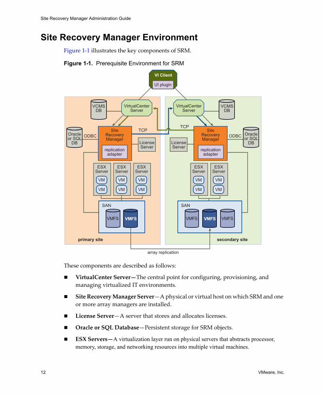
Site Recovery Manager EnvironmentFigure 1‐1 illustrates the key components of SRM.
Figure 1-1. Prerequisite Environment for SRM
These components are described as follows:
VirtualCenter Server—The central point for configuring, provisioning, and managing virtualized IT environments.
Site Recovery Manager Server—A physical or virtual host on which SRM and one or more array managers are installed.
License Server—A server that stores and allocates licenses.
Oracle or SQL Database—Persistent storage for SRM objects.
ESX Servers—A virtualization layer run on physical servers that abstracts processor, memory, storage, and networking resources into multiple virtual machines.
primary site secondary site
replicationadapter
SAN
VMFSVMFS
UI plugin
TCPTCP
ODBC ODBC
array replication
SiteRecoveryManager
replicationadapter
SiteRecoveryManager
VMFS
VirtualCenterServer
VirtualCenterServer
SAN
VMFS VMFS
ESXServer
LicenseServer
LicenseServer
Oracleor SQL
DB
VCMSDB
Oracleor SQL
DB
VCMSDB
VI Client
VM
VM
ESXServer
VM
VM
ESXServer
VM
VM
ESXServer
VM
VM
ESXServer
VM
VM
VMware, Inc. 13
Chapter 1 Overview of Site Recovery Manager
SAN— Storage area network (Fibre Channel or iSCSI arrays) supporting array‐based replication.
VMware File System (VMFS)—A clustered file system that is optimized for storing virtual machines.
Array-Based ReplicationSRM supports array‐based replication in which one or more storage arrays at the protected site replicate their data to peer arrays at the recovery site. Storage replication adapters (SRAs) are array‐specific programs that array vendors provide to support the use of array‐based replication by SRM. SRAs are not part of an SRM release. Your array vendor provides and supports SRAs. You can also download them from the VMware Web site. You must install SRAs specific to the arrays that you want to use with SRM on the SRM server host.
LUN Replication and Datastores
Each storage array supports a set of LUNs (logical storage units comprising one or more physical devices). A given LUN may or may not be replicated. Because Virtual Machine File System (VMFS) datastores can span multiple LUNs, SRM must ensure that all LUNs in a datastore are replicated.
Before virtual machine protection is configured, SRM presents a list of datastore groups and the virtual machines they contain. If the list of datastore groups is not what you expected, correct it before you continue. You can use Storage VMotion (ESX 3.5 and higher) to move individual virtual machines. If the wrong set of LUNs is replicated, reconfigure the replication.
Protection Groups
A protection group is a group of virtual machines that failover together. One protection group must be created for each replicated datastore. After the protection groups are created at the protected site, they (and their virtual machines) must also be added to recovery plans on the recovery site to complete the SRM setup.
When new virtual machines are created on replicated datastores, events are created (and alarms can be associated with those events) that notify you when they are triggered. When this happens, go to the protection group, find the unconfigured virtual machines, and modify the settings for each virtual machine.
NOTE This verification step is a critical checkpoint that eliminates one of the biggest sources of error in disaster recovery plans.
Site Recovery Manager Administration Guide
14 VMware, Inc.
Site Recovery Manager Process OverviewWith SRM, you can set up a recovery site that continuously replicates your production site. You develop a disaster recovery plan, resulting in a process that is tested to meet your recovery objectives. If a disaster occurs, the failover process enables you to bring resources back into service in order of priority.
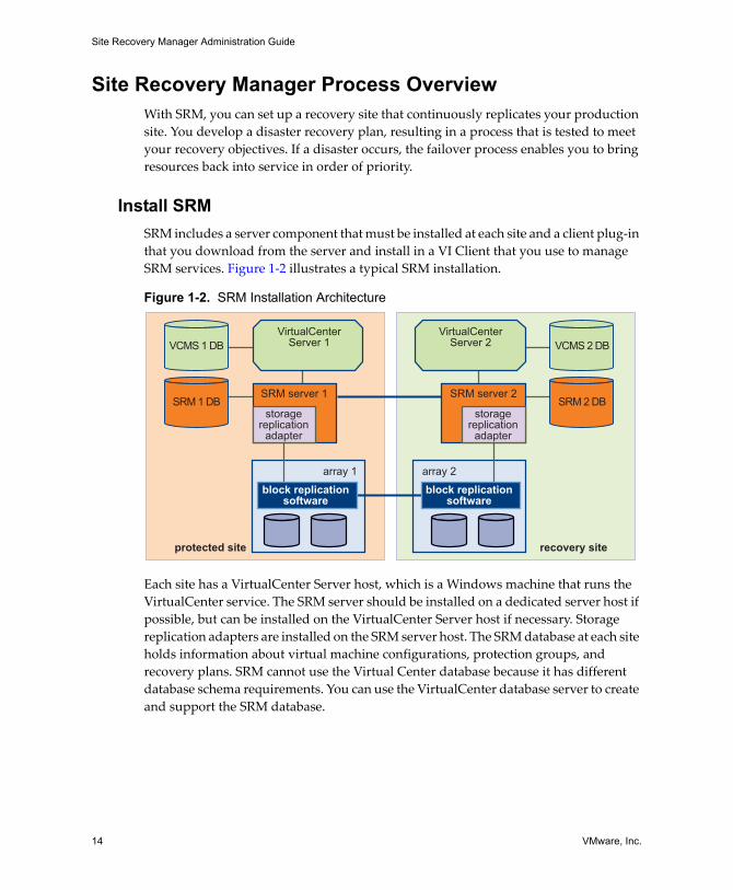
Install SRMSRM includes a server component that must be installed at each site and a client plug‐in that you download from the server and install in a VI Client that you use to manage SRM services. Figure 1‐2 illustrates a typical SRM installation.
Figure 1-2. SRM Installation Architecture
Each site has a VirtualCenter Server host, which is a Windows machine that runs the VirtualCenter service. The SRM server should be installed on a dedicated server host if possible, but can be installed on the VirtualCenter Server host if necessary. Storage replication adapters are installed on the SRM server host. The SRM database at each site holds information about virtual machine configurations, protection groups, and recovery plans. SRM cannot use the Virtual Center database because it has different database schema requirements. You can use the VirtualCenter database server to create and support the SRM database.
protected site recovery site
storagereplication
adapter
storagereplication
adapter
block replicationsoftware
block replicationsoftware
SRM server 1 SRM server 2
VirtualCenterServer 1
VirtualCenterServer 2
array 1 array 2
SRM 1 DB
VCMS 1 DB
SRM 2 DB
VCMS 2 DB
VMware, Inc. 15
Chapter 1 Overview of Site Recovery Manager
Installing SRM includes the following tasks:
1 Configure SRM databases at both sites.
2 Install the SRM server at both sites, and connect each server to its corresponding database.
3 Install the storage replication adapters for your arrays on the SRM server at each site.
4 Install the SRM client plug‐in into one or more VirtualCenter clients at each site.
5 Use the SRM client to connect the protected and recovery sites.
6 Use the SRM client to configure the array managers at each site.
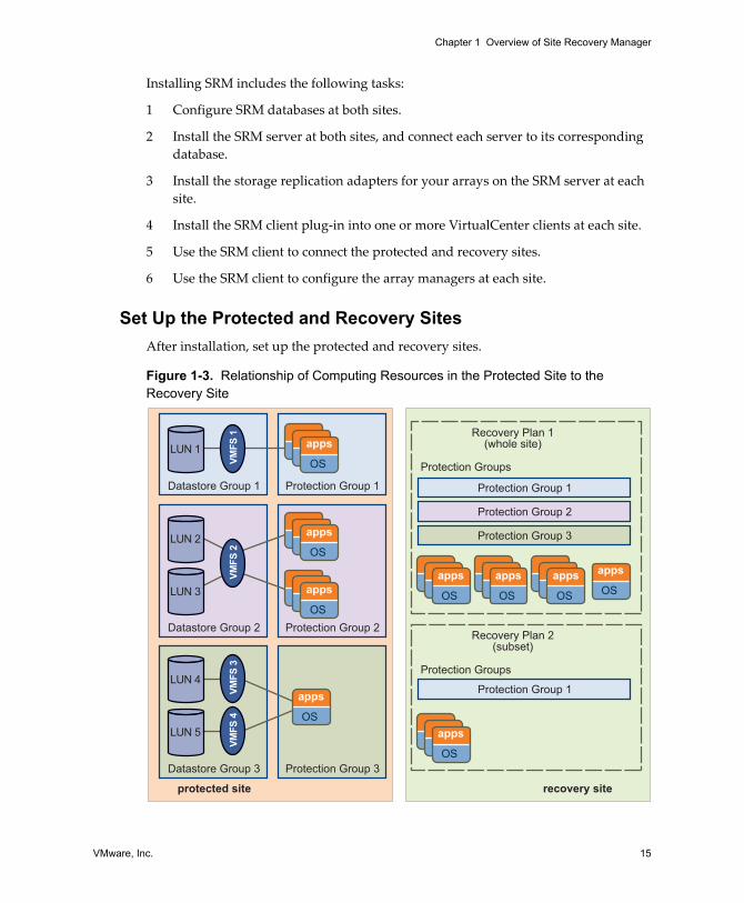
Set Up the Protected and Recovery SitesAfter installation, set up the protected and recovery sites.
Figure 1-3. Relationship of Computing Resources in the Protected Site to the Recovery Site
protected site recovery site
Datastore Group 1 Protection Group 1 Protection Group 1
Protection Groups
Recovery Plan 1(whole site)
Recovery Plan 2(subset)
Protection Groups
Protection Group 2
Protection Group 3
LUN 1
LUN 2
LUN 3
LUN 4
LUN 5
VMFS
1VM
FS 3
VMFS
2VM
FS 4
apps
OS
apps
OS
Protection Group 1
apps
OS
apps
OS
apps
OS
Datastore Group 2 Protection Group 2
Datastore Group 3 Protection Group 3
apps
OS
apps
OS
apps
OS
apps
OS
Site Recovery Manager Administration Guide
16 VMware, Inc.
On the protected site, virtual machines are assigned to protection groups. A protection group is a collection of virtual machines that all use the same datastore group (the same set of replicated LUNs) and failover together.
Use protection groups to control the order in which virtual machines are restored after a failover. For example, critical business applications might be assigned to Protection Group 1, while lower priority applications are assigned to Protection Group 2 and optional applications are assigned to Protection Group 3. In the recovery plan, Protection Group 1 fails over first, followed by group 2, and then group 3.
On the recovery site, create one or more recovery plans. A recovery plan is an ordered set of steps that control what happens during a failover. You can develop multiple recovery plans to address multiple disaster scenarios. Setting up the protected and recovery sites includes the following tasks:
1 Understand the datastore groups you have available. SRM determines these using information from the storage replication adapters.
2 Create inventory maps for the protected virtual machines.
3 Create protection groups for each datastore group.
4 Configure protection group settings, which provide configuration defaults for all virtual machines in the protection group.
5 Create a recovery plan, with prompts, script callouts, and notifications as needed.
Configure Virtual MachinesSRM enables you to specify inventory preferences that control how virtual machine resources such as folders, resource pools, and networks at the protected site are mapped to similar resources at the recovery site. This inventory mapping ensures that protected virtual machines are configured properly to power on and connect to the network at the recovery site.
VMware, Inc. 17
Chapter 1 Overview of Site Recovery Manager
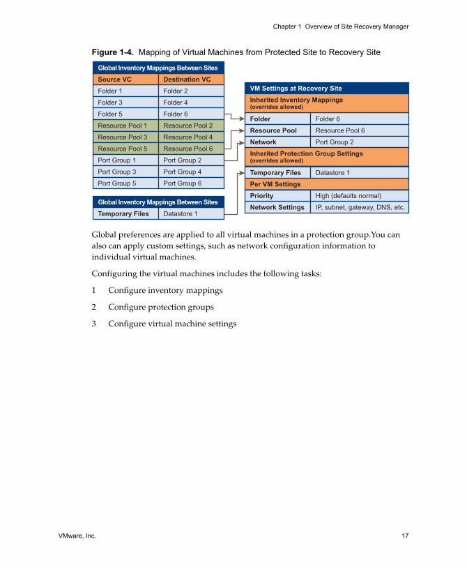
Figure 1-4. Mapping of Virtual Machines from Protected Site to Recovery Site
Global preferences are applied to all virtual machines in a protection group.You can also can apply custom settings, such as network configuration information to individual virtual machines.
Configuring the virtual machines includes the following tasks:
1 Configure inventory mappings
2 Configure protection groups
3 Configure virtual machine settings
Folder 1 Folder 2
Source VC Destination VCGlobal Inventory Mappings Between Sites
Folder 3 Folder 4
Folder 5 Folder 6
Resource Pool 1 Resource Pool 2
Resource Pool 3 Resource Pool 4
Resource Pool 5 Resource Pool 6
Port Group 1 Port Group 2
Port Group 3 Port Group 4
Port Group 5 Port Group 6
Temporary Files Datastore 1
Global Inventory Mappings Between Sites
Folder Folder 6
Per VM Settings
VM Settings at Recovery Site
Resource Pool Resource Pool 6
Network Port Group 2
Network Settings IP, subnet, gateway, DNS, etc.
Priority High (defaults normal)
Inherited Protection Group Settings(overrides allowed)
Inherited Inventory Mappings(overrides allowed)
Temporary Files Datastore 1

Site Recovery Manager Administration Guide
18 VMware, Inc.
VMware, Inc. 19
2
This chapter describes the hardware, operating system, and licensing requirements for VMware Site Recovery Manager (SRM). Use the information in this chapter to ensure that your environment meets the requirements for installation.
See the Site Recovery Manager Compatibility Matrixes for a complete list of SRM compatibility requirements.
This chapter includes the following topics:
“Prerequisites for SRM Installation” on page 19
“SRM Hardware and Software Requirements” on page 20
“SRM Database Requirements” on page 21
“Configuration Maximums” on page 23
“SRM Licensing” on page 24
Prerequisites for SRM Installation VMware Infrastructure must meet the following requirements:
The VirtualCenter Server 2.5 Update 1 or higher and VI Client 2.5 installed and running at the protected and recovery sites. The VirtualCenter Server host should have a static IP address if possible.
Virtual machines residing on ESX hosts that the VirtualCenter Server manages, in datastores hosted on replicated arrays.
No replicated datastore can be accessible from more than one datacenter.
System Requirements 2
Site Recovery Manager Administration Guide
20 VMware, Inc.
Storage arrays must meet the following requirements:
Array‐based replication and storage replication adapters installed and configured at the protected and recovery sites.
Array management might also require the installation of other vendor‐provided components. Some of these components might need to be installed on the same host as the SRM server; others might require only network access by the SRM server.
SRM might occasionally need to rescan storage arrays. You can improve array rescan times by changing default value of the Scsi.RescanAllHbas on ESX hosts. If rescan times on ESX hosts are longer than 10 minutes, you may want to set the value of this option to 1.
Masking and zoning is configured for replicated LUNs to remote ESX hosts for failover. VMware recommends that you configure storage to create clones or snapshots of the replicated LUNs. Snapshots or clones must be masked to the recovery ESX hosts.
Unless the SRM server and VirtualCenter server are installed on the same host, you must add the following ports to the Windows Firewall exception list to enable interprocess communication between SRM and VirtualCenter:
SRM Communications SOAP port (default 8095)
SRM Client Download HTTP port (default 8096)
SRM External API SOAP port (default 9007)
SRM Hardware and Software RequirementsThe SRM hardware must meet the following requirements:
Processor – 2.0GHz or higher Intel or AMD x86 processor.
Memory – 2GB minimum.
Disk Storage – 2GB minimum.
Networking ‐ Gigabit recommended.
VMware SRM runs on the following Microsoft Windows operating systems:
Windows XP Professional with SP2
Windows 2003 Server R2
Windows 2003 Server SP1 (all releases except 64‐bit)
Windows 2000 Server SP4 with Update Rollup 1
VMware, Inc. 21
Chapter 2 System Requirements
The SRM plug‐in is installed in the VI Client. The SRM plug‐in is designed to run on Microsoft Windows operating systems and is designed for the 32‐bit versions of the following operating systems:
Windows 2000 Professional with SP4 Update Rollup 1 (MSI installer version 3.1.4000.2435 or later)
Windows XP Professional 32‐bit with SP2 (MSI installer version 3.1.4000.2435 or later)
Windows 2003 with SP1 (all releases except 64‐bit)
Windows 2003 Server R2
Windows Vista Business
Windows Vista Enterprise
The VI Client requires the Microsoft .NET 2.0 Framework. If your system does not have it installed, the VI Client installer installs it.
SRM Database RequirementsThe SRM database at each site holds information about virtual machine configurations, protection groups, and recovery plans. SRM cannot use the VirtualCenter database because it has different database schema requirements. You can use the VirtualCenter database server to create and support the SRM database.
Each site requires its own instance of the SRM database. The database must exist before SRM can be installed. You must not reinitialize the database after SRM installation is complete. Doing so will cause SRM to fail. If you must reinitialize the SRM database, reinstall SRM, specifying a new database connection, after the reinitialization is complete.
Each database requires additional configuration after the basic installation. See “Microsoft SQL Server Configuration” on page 22 and “Oracle Server Configuration” on page 23.
NOTE The SRM server host should have a static IP address if possible.
Site Recovery Manager Administration Guide
22 VMware, Inc.
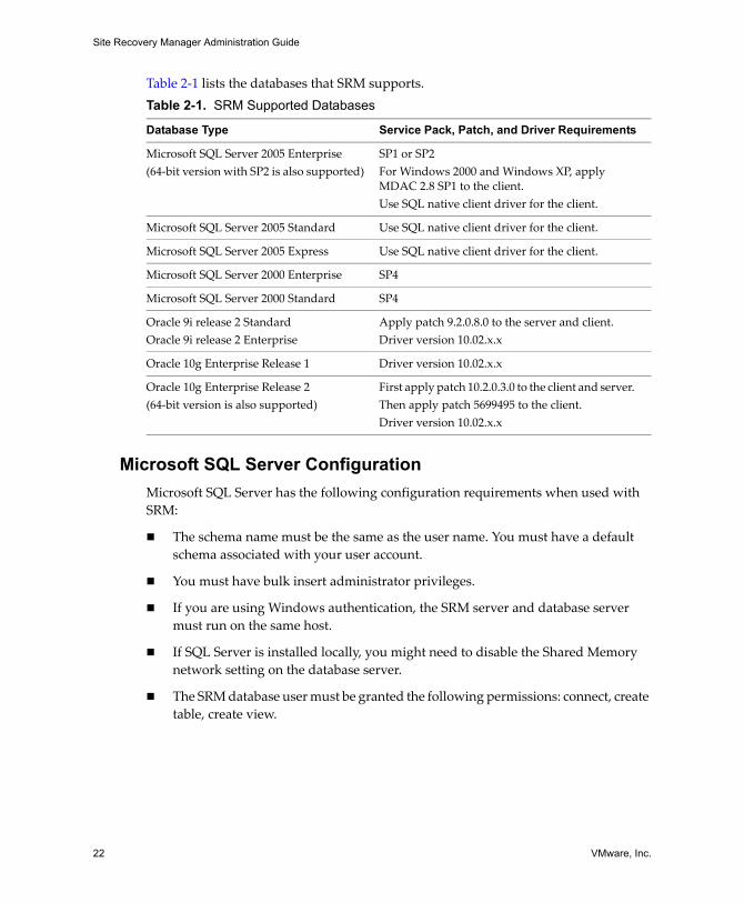
Table 2‐1 lists the databases that SRM supports.
Microsoft SQL Server ConfigurationMicrosoft SQL Server has the following configuration requirements when used with SRM:
The schema name must be the same as the user name. You must have a default schema associated with your user account.
You must have bulk insert administrator privileges.
If you are using Windows authentication, the SRM server and database server must run on the same host.
If SQL Server is installed locally, you might need to disable the Shared Memory network setting on the database server.
The SRM database user must be granted the following permissions: connect, create table, create view.
Table 2-1. SRM Supported Databases
Database Type Service Pack, Patch, and Driver Requirements
Microsoft SQL Server 2005 Enterprise(64‐bit version with SP2 is also supported)
SP1 or SP2 For Windows 2000 and Windows XP, apply MDAC 2.8 SP1 to the client.Use SQL native client driver for the client.
Microsoft SQL Server 2005 Standard Use SQL native client driver for the client.
Microsoft SQL Server 2005 Express Use SQL native client driver for the client.
Microsoft SQL Server 2000 Enterprise SP4
Microsoft SQL Server 2000 Standard SP4
Oracle 9i release 2 StandardOracle 9i release 2 Enterprise
Apply patch 9.2.0.8.0 to the server and client.Driver version 10.02.x.x
Oracle 10g Enterprise Release 1 Driver version 10.02.x.x
Oracle 10g Enterprise Release 2(64‐bit version is also supported)
First apply patch 10.2.0.3.0 to the client and server. Then apply patch 5699495 to the client.Driver version 10.02.x.x
VMware, Inc. 23
Chapter 2 System Requirements
Oracle Server ConfigurationOracle Server has the following configuration requirements when used with SRM:
If you are using an Oracle 9i server, the SRM Bulk Insert feature must be disabled. Edit the vmware-dr.xml configuration file and change the EnableBulkInsert setting to false. The default location of this file is: C:\Program Files\VMware\VMware Site Recovery Manager\config\. After you change the configuration file, restart the VMware Site Recovery Manager Service service for each SRM server that is using this database.
Use driver version 10.02.x.x for all supported database versions.
The SRM database user must be granted the following permissions: connect, resource, create session, create view.
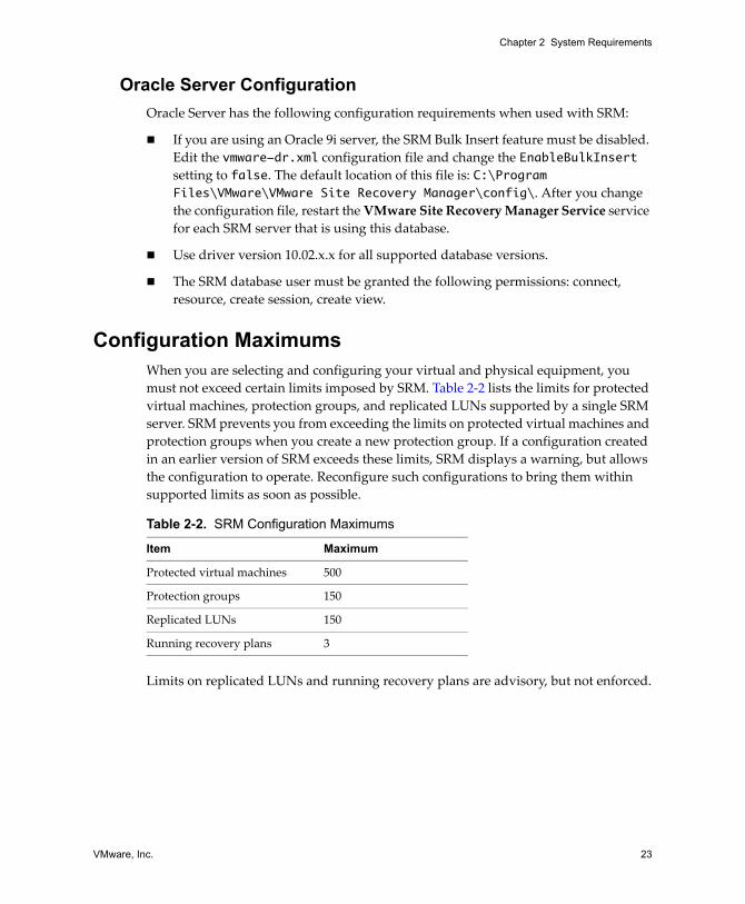
Configuration MaximumsWhen you are selecting and configuring your virtual and physical equipment, you must not exceed certain limits imposed by SRM. Table 2‐2 lists the limits for protected virtual machines, protection groups, and replicated LUNs supported by a single SRM server. SRM prevents you from exceeding the limits on protected virtual machines and protection groups when you create a new protection group. If a configuration created in an earlier version of SRM exceeds these limits, SRM displays a warning, but allows the configuration to operate. Reconfigure such configurations to bring them within supported limits as soon as possible.
Limits on replicated LUNs and running recovery plans are advisory, but not enforced.
Table 2-2. SRM Configuration Maximums
Item Maximum
Protected virtual machines 500
Protection groups 150
Replicated LUNs 150
Running recovery plans 3
Site Recovery Manager Administration Guide
24 VMware, Inc.
SRM LicensingSRM requires two types of license keys:
A protection‐enablement license key (SRM_PROTECTED_HOST) that specifies the number of ESX CPUs that can run protected virtual machines at a site. Install this key at the protected site to enable failover. Install it at the recovery and protected sites to enable bidirectional operation (failback).
A site enablement license key (PROD_SRM) that must be installed at the protected site and the recovery site. These keys are supplied when you purchase your protection‐enablement keys.
To obtain your license keys, go to the Site Recovery Manager Product Information page at the VMware Web site.
SRM licensing checks for a valid license when the host license is first installed and each time the SRM hostd program restarts. Licenses acquired from a license server are checked every five minutes. If licenses are not in compliance, VirtualCenter triggers a licensing alarm. VMware recommends that you configure alerts for triggered licensing events so that licensing administrators are notified by email. See “Alerting and Monitoring” on page 75 for more information.
Import License FilesWhen the VMware license server is installed, you can import SRM license files into your license server. You must install the per‐site license at the protected and recovery sites. You must install the protection‐enablement license at the recovery site to enable failover, and at the recovery and protected sites to enable bidirectional operation (failback).
For more information about the VMware license server, see the ESX Server 3 Installation Guide.
To enable an SRM license
1 Log in to the computer that runs the license server application.
The protected and recovery sites should each have their own license servers.
2 Copy the SRM license file that includes the PROD_SRM key to C:\Program Files\Vmware\VMware License Server\Licenses\.
License files must have a .lic extension.
3 If this is a site where you want to enable protected virtual machines to run, copy the SRM license file that includes the SRM_PROTECTED_HOST key to C:\Program Files\Vmware\VMware License Server\Licenses\.
VMware, Inc. 25
Chapter 2 System Requirements
4 Launch VMware License Server Tools by choosing Start > Programs > VMware > VMware License Server > VMware License Server Tools.
5 Click the Start/Stop/Reread tab.
6 Click ReRead License File to load the new license files.
7 Restart the SRM server.

Site Recovery Manager Administration Guide
26 VMware, Inc.
VMware, Inc. 27
3
You must install an SRM server at the protected site and also at the recovery site. After the SRM servers have been installed, you can download the client plug‐in from either server to any VI Client and use that client to configure and manage SRM at either site.
SRM requires the support of a VirtualCenter server at each site.The SRM installer must be able to connect with this server during installation. If you cannot install SRM on a dedicated server host, you can install it on the same host where the VirtualCenter Server is installed.
Installing SRM includes the following tasks:
1 Install SRM on the protected site.
2 Install SRM at the recovery site.
3 Using a VI Client, connect to a VirtualCenter Server at the protected or recovery site and download the SRM plugin.
Updating SRM includes the following tasks:
1 Back up the SRM database at the protected and recovery sites.
2 Update SRM on the protected site.
3 Update SRM at the recovery site.
4 Using a VI Client on which the SRM plug‐in is not installed, connect to a VirtualCenter Server at the protected or recovery site and download a new SRM plug‐in.
Installing or Updating Site Recovery Manager 3
Site Recovery Manager Administration Guide
28 VMware, Inc.
This chapter includes the following topics:
“Install Site Recovery Manager” on page 28
“Update Site Recovery Manager” on page 31
“Update Site Recovery Manager” on page 31
Install Site Recovery ManagerBefore installing SRM, ensure that you completed all the requirements listed in Chapter 2, “System Requirements,” on page 19. In particular, you need the following information for each site:
The hostname or IP address of a running VirtualCenter Server—SRM and VirtualCenter can reside on the same host or on different hosts. During SRM installation, you must supply the VirtualCenter hostname or IP address.
The username and password of the VirtualCenter administrator—During SRM installation, you must supply a valid username and password for the VirtualCenter administrator.
A username and password for the SRM database—For more information, see “SRM Database Requirements” on page 21.
To install SRM
1 Log in to the server host on which to install SRM.
To install SRM, you must log in as a member of the host’s Administrators group.
2 Download the SRM installation file to a folder on the host, or open a folder on the network that contains this file.
3 Double‐click the SRM installer icon to begin installation.
The installer examines the set of installed VMware software on the host. If it detects an existing installation of SRM, it prompts you to verify that you want to update the existing installation. For more information about updating SRM, see “To update SRM” on page 31.
4 Click Next on the Welcome to the installation wizard screen.
5 On the License Agreement page, click I accept the terms in the license agreement and then click Next.
NOTE During installation, SRM stores the hostnames of the SRM server and VirtualCenter server hosts. If you have to change either of these host names, you must re‐install SRM.

VMware, Inc. 29
Chapter 3 Installing or Updating Site Recovery Manager
6 At the Destination Folder screen, choose the folder in which you want to install SRM and click Next.
The pathname to the installation folder cannot be longer than 240 characters, and cannot include any non‐ASCII characters.
7 Enter the following information about the VirtualCenter server at the site where you are installing SRM:
VirtualCenter Address ‐ Enter the hostname or IP address of the VirtualCenter Server.
The VirtualCenter Server and the SRM server must be in the same domain. Enter the hostname in lowercase. After installation is complete and you are configuring the connection between the protected and recovery sites, you must supply this hostname or IP address exactly as you enter it here.
VirtualCenter Port ‐ Accept the default or enter another port.
VirtualCenter Username ‐ Enter a user ID that has administrator privileges on the specified VirtualCenter Server.
VirtualCenter Password ‐ Enter the password for the specified user ID.
Click Next. The installer contacts the specified Virtual Center server and validates the information you supplied.
8 Select a source for the certificate used to authenticate server connections:
To have SRM create and install a certificate, select Automatically generate certificate and click Next.
Enter text values for your organization and organization unit, typically your company name and the name of your group within the company. The maximum length of the combined values cannot exceed 80 characters.
To use an existing PKCS #12 certificate file, select Use a PKCS #12 certificate file and click Next.
Enter the path to the certificate file. The certificate file must file contain exactly one certificate with exactly one private key matching the certificate.
Enter the certificate password if necessary.
9 Enter the following additional information:
Local Site Name—A unique name for this installation of SRM. Each installation of SRM at a site must have a unique identifier.
Administrator e‐mail—The e‐mail address of the person or group who monitors SRM and responds to alerts or notifications.
Site Recovery Manager Administration Guide
30 VMware, Inc.
Additional email (optional)—The e‐mail address of an additional person or group who should receive any alerts or notifications.
Local Host—The name or IP address of the local host. This value is obtained by the SRM installer and need only be changed if it is incorrect (for example, if the local host has more than one network interface and the one detected by the SRM installer is not the one you want to use).
Listener Ports—The SOAP and HTTP port numbers for network traffic. SOAP is used to receive requests from SRM; HTTP is used for downloading the SRM plug‐in. Default values are supplied.
API Listener Ports—The SOAP and HTTP port numbers for network traffic from the SRM API. Default values are automatically supplied. For more information, see the Site Recovery Manager API documentation.
Default port values work without modification as long as those ports are not being used by other applications in the system where SRM is being installed. You can modify these values if other services are already using the ports, or if your network administrator prefers to assign specific ports for SRM to use.
10 Enter the following database configuration information and click Next:
Database Client—Click the arrow on the right of the field and select the database client for your site.
Data Source Name—The DSN you want to use for this installation of SRM. Click ODBC DSN Setup to view existing DSNs or create a new one.
Username—A user ID valid for the specified database.
Password—The password for the specified user ID.
Connection Count—The initial connection pool size. Connections in this pool are created by the SRM installer. If these connections are all in use and a new one is needed, it is created if doing so would not cause the number of connections specified by Max Connections to be exceeded. It is faster for SRM to use a connection from the pool than to create a new one.
Max Connections—The maximum number of connections to open to the database at one time. If your database administrator has restricted the number of connections that the database can have open, the value you supply here must not exceed that number.
11 Click Install.
12 When the wizard completes, click Finish.
VMware, Inc. 31
Chapter 3 Installing or Updating Site Recovery Manager
Update Site Recovery ManagerWhen you update Site Recovery Manager, information about Virtual Center server connections, certificates, and database configuration is read from the existing installation and reused by the new installation.
To update SRM
1 Log in to the SRM server host.
To install SRM, you must log in as a member of the host’s Administrators group
2 Download the SRM installation file to a folder on the host, or open a folder on the network that contains this file.
3 Double‐click the SRM installation file icon to begin the update.
The installer examines the set of installed VMware software on the host. If it detects an existing installation of SRM, it prompts you to verify that you want to update the existing installation.
Click Yes to continue with the update.
4 Click Next on the Welcome to the update wizard page. The wizard prompts you to verify that you have backed up the SRM database.
Click No to pause the installation while you back up the database.
Click Yes if you have backed up the database and want to proceed with the installation. The installer reads configuration data from the existing installation and uses it to complete the update.
5 When the wizard completes, click Finish.
You might be prompted to shut down and restart Windows.
Install the Site Recovery Manager Plug-InAfter you have installed or updated SRM, use a VI Client to connect to the VirtualCenter Server at the protected or recovery site, then download the plug‐in from the server and enable it in the VI Client.
NOTE Before you begin the update, back up your current SRM database. The update wizard requires you to verify that the database is backed up, and pauses until you confirm that it is.
Site Recovery Manager Administration Guide
32 VMware, Inc.
To download and install the SRM plug-in
1 Start a VI Client and connect to a VirtualCenter Server at the protected or recovery site.
2 On the VI Client menu bar, select Plugins > Manage Plugins.
3 On the Available tab, locate the VMware VirtualCenter Site Recovery plug‐in and click Download and install.
4 When the download completes, the plug‐in installation wizard appears. Click Next to start the wizard.
5 Click I accept the terms in the license agreement, and click Next.
6 Click Install.
7 Click Finish.
You might be prompted to shut down and restart Windows.
8 Click the Installed tab.
9 Check the Enabled check box for the Site Recovery plug‐in.
The Site Recovery icon appears on the toolbar.
Updating Database CredentialsDuring installation, SRM encrypts and stores the database credentials that you specify. If any of these credentials change (for example, if the database username or password changes), you must change the stored credentials by running the installcreds.exe utility found in the installation directory.
Reverting to a Previous ReleaseYou must uninstall both SRM and its database when reverting to a previous release.
To revert to a previous release
1 Uninstall SRM at the protected and recovery sites.
Where sites have been paired, SRM at both sites must be uninstalled. If you SRM uninstall SRM from one member of a pair of hosts, the database on the remaining member becomes inconsistent.
2 Uninstall the SRM plug‐in from affected VirtualCenter clients
3 Restore the database used by the previous release, following the procedures documented by your database vendor.
VMware, Inc. 33
4
This chapter describes the VMware Infrastructure Client and provides information about how to use the application to manage SRM and operations such as site pairing, managing users, and accessing log files.
This chapter includes the following topics:
“Use the VI Client to Manage SRM” on page 33
“Connecting the Protected and Recovery Sites” on page 34
“Credential‐Based Authentication” on page 35
“Certificate‐Based Authentication” on page 36
“SRM Users, Groups, Permissions, and Roles” on page 37
“Access SRM Log Files” on page 42
Use the VI Client to Manage SRMThe VI Client is the interface to VirtualCenter Server. When you log in, only those features and functions supported by the type of server you logged on to appear. After you install the SRM plug‐in, the VI Client displays site recovery options.
To log in to SRM from a VI Client session
1 Using the VI Client, log in to the protected site or recovery site VirtualCenter Server.
2 Click the Site Recovery icon on the toolbar.
Managing SRM 4
Site Recovery Manager Administration Guide
34 VMware, Inc.
Site Recovery components in the VI Client include:
Inventory – Located on the left, displays the inventory objects available for SRM, including protection groups and recovery plans.
Summary tab – Displays the relevant information for the protected site and the recovery site.
Setup pane – Displays the options used to configure site failover.
Alarms tab – Lists the configured alarms for SRM.
Permissions tab – Lists the users and groups that have permissions on the selected object and at what level the permission was assigned.
Connecting the Protected and Recovery SitesWhen you start using SRM, establish a secure connection between the protected site and the recovery site. Use the VI Client to pair and manage both sites. Because the VI Client can connect to only one VirtualCenter Server at a time, launch one VI Client to manage each site. Before you connect to the recovery site, you need the following:
The recovery site VirtualCenter Server name or IP address and port number.
The role of Protection SRM Administrator on the recovery site if using credential‐based authentication.
The administrator login for the remote server.
Connections between SRM and either VirtualCenter or another instance of SRM must be authenticated. You can use administrative credentials or trusted certificates to authenticate connections, but you cannot mix authentication methods. The authentication method you choose must be used to secure the connection between the VirtualCenter Server and SRM at each site, and also between the SRM servers at the protected and recovery sites. If you use trusted certificates, both sites must use the same subject name (composed from the organization and organization unit information you supply during installation) in the certificate.
Credential based—Uses a username and password. The account must be an administrator account. The privileges on the VirtualCenter Server specify these credentials. Save the credentials you specify to communicate to the VirtualCenter Server.
Certificate based—Specify a certificate that was signed by a trusted certificate authority. The certificate is most commonly signed by a trusted certificate authority and installed in the VirtualCenter Server and SRM on the protected and recovery sites. This configuration is the most secure connection.
VMware, Inc. 35
Chapter 4 Managing SRM
Credential-Based AuthenticationBy specifying auto‐generated certificates at installation, you are implicitly specifying credential‐based authentication. In this case, the SRM server saves the credentials specified during installation to authenticate all subsequent communication with the local VirtualCenter Server. When this instance of SRM is paired to a remote SRM server, the credentials specified as part of the pairing process are saved to authenticate all subsequent communication with the remote SRM server.
All communication with SRM is protected using SSL encryption, including the transfer of authentication credentials to VirtualCenter and SRM servers.
Pairing Sites with Credential-Based Authentication
Connecting protected and recovery sites using auto‐generated certificates is the default setup for connecting protected and recovery sites.
To connect to protected and recovery sites
1 Using the VI Client, log in to the protected site VirtualCenter Server.
2 Click the Site Recovery icon on the toolbar.
3 In the Protection Setup pane, click Configure.
4 Enter the IP address or hostname and port number for the remote VirtualCenter Server and click Next.
5 Accept the remote site certificate.
This certificate prompt appears when the SRM server does not trust the certificate for the remote VirtualCenter Server.
6 Enter the administrator’s username and password.
7 Accept the remote site certificate.
This certificate prompt appears when the SRM server does not trust the certificate for the remote SRM server.
8 Verify that each step has a check mark and click Finish.
9 Enter the administrator’s username and password for the remote VirtualCenter Server.
10 Accept the remote site certificate.
CAUTION When you enter the hostname for the VirtualCenter Server, use lowercase. The VirtualCenter hostname must be entered exactly the same way (fully qualified or not) during pairing as it was during installation.
Site Recovery Manager Administration Guide
36 VMware, Inc.
11 Using the VI Client, log in to the recovery site VirtualCenter Server.
12 Click the Site Recovery icon on the toolbar.
This submits the required credentials to log in to the remote VirtualCenter Server.
13 Accept the remote site certificate.
The Protected Site and Recovery Site panes display the connection information after a successful pairing.
Certificate-Based AuthenticationCertificate‐based authentication requires the use of certificates signed by a common trusted certificate authority on all servers involved in your SRM installation. This includes both VirtualCenter and SRM servers. Such a certificate may be referred to as a “trusted certificate.”
By specifying a trusted certificate at installation, you are implicitly choosing to use certificate‐based authentication. In this case, the SRM server uses the certificate specified during installation to authenticate all subsequent communication with the local VirtualCenter Server. The SRM server does not save credentials specified during the initial installation.
Pairing Sites Using Certificate-Based Authentication
VMware recommends that you use certificate‐based authentication.
To connect to protected and recovery sites
1 Using the VI Client, log in to the protected‐site VirtualCenter Server.
2 Click the Site Recovery icon on the toolbar.
3 In the Setup pane, click Configure.
4 Enter the IP address or hostname and port number for the remote VirtualCenter Server and click Next.
5 Verify that each step has a check mark and click Close.
6 From the protected site, enter the remote credentials in the Remote VirtualCenter Server dialog box.
7 Using the VI Client, log in to the recovery‐site VirtualCenter Server.
8 Click the Site Recovery icon on the toolbar and submit the required credentials to complete the pairing.
The connection information appears after a successful pairing.
VMware, Inc. 37
Chapter 4 Managing SRM
SRM Users, Groups, Permissions, and RolesSRM uses the same authorization model as VirtualCenter Server. The set of permissions applied to or inherited by an object determine the operations that are allowed on the object and the list of roles that can perform those operations. Managed objects in the SRM inventory can have specific permissions applied. There are two ways to control permission to execute SRM operations:
Adding users – Assign users to the predefined roles.
Adding roles – Create a role, add the administrators, and then add the right permissions to the role.
To manage permissions and roles, you must log in to the VirtualCenter Server with the administrator account.
The Permissions tab lists the users and groups that have permissions on the selected object and at what level the permission was assigned.
You must be in Administration view for the Roles menu item to be enabled. The Permissions tab displays the following:
User/Group—The user or group that exists in SRM.
Role—Set of privileges assigned to an existing user or group.
Defined in—The object in which the user, group, and role is defined.
SRM PermissionsTo obtain the full ability of an administrator of the protected site and the recovery site, define the following permissions:
Protected site:
Read‐only at the VirtualCenter root (do not propagate).
Read‐only to Datacenter inventory object (do not propagate).
Protection Virtual Machine Administrator role at the Virtual Machine level (propagate).
NOTE To configure SRM, a user must have both VirtualCenter and SRM permissions. SRM roles such as SRM Protection Administrator and SRM Recovery Administrator do not have specific privileges for VirtualCenter and therefore do not have adequate permissions to perform all SRM operations. The converse is also true. VirtualCenter roles do not provide any SRM privileges. Ensure that SRM users have VirtualCenter and SRM specific roles as appropriate.
Site Recovery Manager Administration Guide
38 VMware, Inc.
Protection SRM Administrator role at the SRM Site Recovery root level (do not propagate).
Protection Groups Administrator role at the SRM Protection Groups level (propagate).
Recovery site:
Recovery Inventory Administrator role at the VirtualCenter root level (do not propagate).
Recovery Datacenter Administrator role at the VirtualCenter datacenter level (do not propagate).
Recovery Host Administrator role at the VirtualCenter host level (do not propagate).
Recovery Virtual Machine Administrator at the VirtualCenter resource pool and VirtualCenter folder levels (propagate).
Recovery SRM Administrator at the SRM root level (do not propagate).
Recovery Plans Administrator at the SRM Recovery Plans level (propagate).
SRM Default RolesThe following SRM‐specific roles are defined on the VirtualCenter Server during SRM installation:
Protection Groups Administrator—Set up and modify protection groups.
Protection SRM Administrator—Pair the protected and recovery sites, and configure inventory mappings.
Protection Virtual Machine Administrator—Set up and modify the protection characteristics of a protected virtual machine.
Recovery Datacenter Administrator—View available datastores and perform recovery virtual machine customization.
Recovery Host Administrator—Configure virtual machine components during recovery.
Recovery Inventory Administrator—View customization specifications for the recovery site.
Recovery Plans Administrator—Reconfigure protection and recovery virtual machines. Also grants the ability to set up and run recovery.
VMware, Inc. 39
Chapter 4 Managing SRM
Recovery SRM Administrator—Configure SAN arrays and create protection profiles.
Recovery Virtual Machine Administrator—Create recovery virtual machines and add them to the resource pool. Also grants the user the ability to reconfigure and customize the recovery virtual machines when a recovery plan is run.
The VirtualCenter Server defines a Read‐Only system role that can be used to grant users the ability to view SRM properties. In addition, the Administrator role can be used to grant users complete control over both the protection and recovery components.
To set up the inventory mappings, a protected site user must be assigned the following roles:
“Protection SRM Administrator” role on the SRM root object.
“Read‐Only” role on the VirtualCenter object being mapped on both the primary and the recovery sites.
Add RolesSome of the default roles (such as Administrator) are preconfigured and cannot be changed. If you have situations that require a different combination of access privileges than the ones set up, create an additional role or modify the provided sample roles to suit your needs.
To add a role
1 Log in to the VI Client as a user with Administrator privileges.
2 From the VI Client, click the Administration button in the navigation bar.
3 Click the Roles tab.
4 Click Add Role.
5 Type a name for the new role.
6 Select the privileges for the new role to have (for example, Site Recovery) and click OK. Click the plus (+) signs to expand the lists, as needed.
Assign VirtualCenter Access PermissionsAssign to new users and groups the roles and permissions to the relevant inventory objects.
Site Recovery Manager Administration Guide
40 VMware, Inc.
To assign a permission to a user or group
1 Log in to the VI Client as a user with administrator privileges.
2 From the VI Client, click the Inventory button in the navigation bar.
3 Click the Permissions tab.
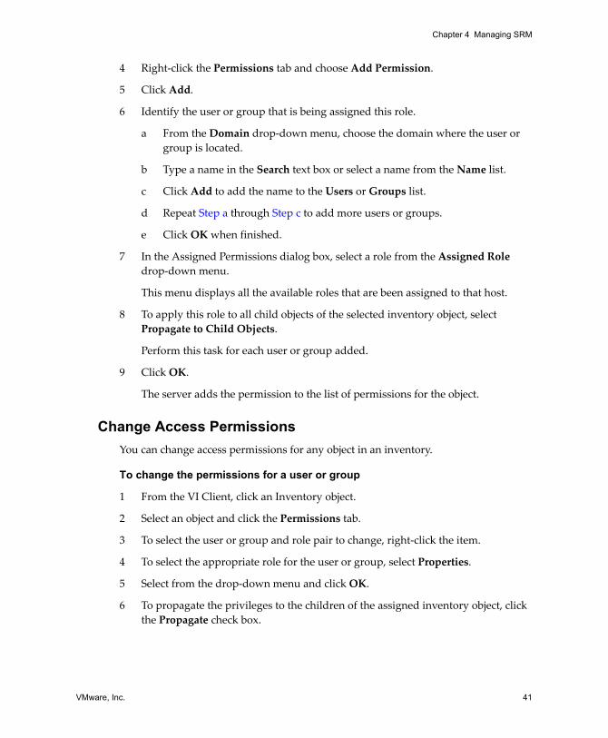
4 Right‐click the Permissions tab and choose Add Permission.
5 Click Add.
6 Identify the user or group that is being assigned this role:
a From the Domain drop‐down menu, choose the domain where the user or group is located.
b Type a name in the Search box or select a name from the Name list.
If you know the user or group name, you can type it in the Name field.
c Click Add to add the name to the Users or Groups list.
d Repeat Step a through Step c to add additional users or groups and click OK when finished.
7 To apply this role to all child objects of the selected inventory object, select Propagate to Child Objects.
8 Verify that the users and groups are assigned to the appropriate permissions and click OK.
9 Click OK.
The server adds the permission to the list of permissions for the object.
Add a New User Group and Role to SRMAssign to new users and groups the roles and permissions to the relevant SRM inventory objects.
To assign a user or group permission
1 Log in to the VI Client as a user with Administrator privileges.
2 Click Site Recovery in the navigation bar.
If the protected and recovery sites are paired, you might need to enter login information for the recovery site.
3 Click the Permissions tab of the SRM Inventory object.
VMware, Inc. 41
Chapter 4 Managing SRM
4 Right‐click the Permissions tab and choose Add Permission.
5 Click Add.
6 Identify the user or group that is being assigned this role.
a From the Domain drop‐down menu, choose the domain where the user or group is located.
b Type a name in the Search text box or select a name from the Name list.
c Click Add to add the name to the Users or Groups list.
d Repeat Step a through Step c to add more users or groups.
e Click OK when finished.
7 In the Assigned Permissions dialog box, select a role from the Assigned Role drop‐down menu.
This menu displays all the available roles that are been assigned to that host.
8 To apply this role to all child objects of the selected inventory object, select Propagate to Child Objects.
Perform this task for each user or group added.
9 Click OK.
The server adds the permission to the list of permissions for the object.
Change Access PermissionsYou can change access permissions for any object in an inventory.
To change the permissions for a user or group
1 From the VI Client, click an Inventory object.
2 Select an object and click the Permissions tab.
3 To select the user or group and role pair to change, right‐click the item.
4 To select the appropriate role for the user or group, select Properties.
5 Select from the drop‐down menu and click OK.
6 To propagate the privileges to the children of the assigned inventory object, click the Propagate check box.
Site Recovery Manager Administration Guide
42 VMware, Inc.
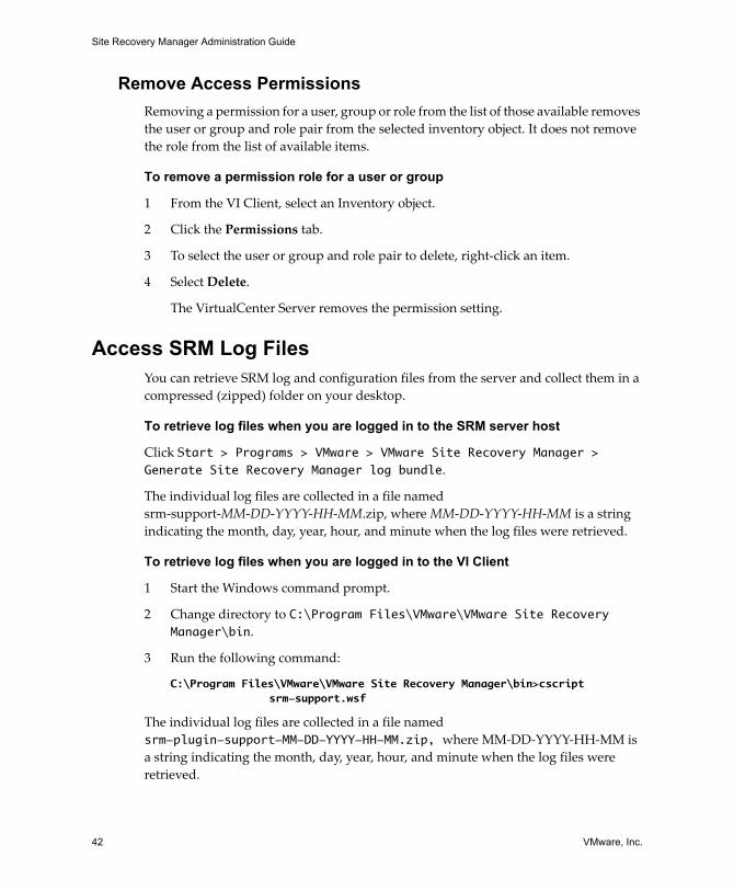
Remove Access PermissionsRemoving a permission for a user, group or role from the list of those available removes the user or group and role pair from the selected inventory object. It does not remove the role from the list of available items.
To remove a permission role for a user or group
1 From the VI Client, select an Inventory object.
2 Click the Permissions tab.
3 To select the user or group and role pair to delete, right‐click an item.
4 Select Delete.
The VirtualCenter Server removes the permission setting.
Access SRM Log FilesYou can retrieve SRM log and configuration files from the server and collect them in a compressed (zipped) folder on your desktop.
To retrieve log files when you are logged in to the SRM server host
Click Start > Programs > VMware > VMware Site Recovery Manager > Generate Site Recovery Manager log bundle.
The individual log files are collected in a file named srm‐support‐MM‐DD‐YYYY‐HH‐MM.zip, where MM‐DD‐YYYY‐HH‐MM is a string indicating the month, day, year, hour, and minute when the log files were retrieved.
To retrieve log files when you are logged in to the VI Client
1 Start the Windows command prompt.
2 Change directory to C:\Program Files\VMware\VMware Site Recovery Manager\bin.
3 Run the following command:
C:\Program Files\VMware\VMware Site Recovery Manager\bin>cscript srm-support.wsf
The individual log files are collected in a file named srm-plugin-support-MM-DD-YYYY-HH-MM.zip, where MM‐DD‐YYYY‐HH‐MM is a string indicating the month, day, year, hour, and minute when the log files were retrieved.
VMware, Inc. 43
5
This chapter describes the steps required to configure VMware Site Recovery Manager (SRM) protected sites, including creating protection groups, configuring storage array managers, inventory preferences, and editing virtual machine settings.
This chapter includes the following topics:
“Configuring the Protected Site” on page 43
“Configure Array Managers” on page 44
“Repair Array Managers” on page 46
“Configure Inventory Preferences” on page 47
“Create a Protection Group” on page 48
“Configuring Virtual Machine Properties” on page 49
“Add Message and Command Steps” on page 52
“IP Address Mapping” on page 53
Configuring the Protected Site Configuring protection at the protected site includes the following steps:
1 Install the storage replication adapters.
Consult the documentation from your storage vendor if you need assistance. You must add the necessary array scripts and restart the SRM service before you configure array managers.
2 Configure the array managers to allow SRM to discover replicated LUNs and create datastore groups.
Protected Site Configuration 5
Site Recovery Manager Administration Guide
44 VMware, Inc.
3 Configure inventory preferences to set the global mappings for all protection groups to inherit.
4 Create protection groups that define virtual machines that failover together.
5 Configure individual virtual machines and set the defaults to inherit from inventory mappings and the settings on their protection group.
Requirements for VMware Infrastructure ConfigurationBefore you configure array managers, you need the following VMware Infrastructure configuration:
A datacenter on the protected and recovery sites.
ESX hosts at the protected and recovery sites.
If you need to support use of certain types of snapshots at the recovery site (snapshots taken when the virtual machine is powered on or suspended), the ESX hosts at both sites must have compatible CPUs, as defined in the VMware knowledge base articles VMotion CPU Compatibility Requirements for Intel Processors (article 1991) and VMotion CPU Compatibility Requirements for AMD Processors (article 1992). The hosts must also have the same BIOS features enabled. If the servers’ BIOS configurations do not match, they still show a compatibility error message even if they are otherwise identical. The two most common features to check are Non‐Execute Memory Protection (NX / XD) and Virtualization Technology (VT / AMD‐V).
Virtual machines to be protected on the protected site.
For information about configuring datacenters, hosts, and resource pools, see the VMware Infrastructure Server Configuration Guide.
Configure Array ManagersAfter the protected and recovery sites are connected to each other, configure the array managers so that SRM can identify available arrays and replicated LUNs. Array managers use storage replication adapters, which are supplied by array vendors. When you configure array managers, you supply information about the arrays that you want to use. SRM uses this information to discover the arrays available to the SRM server and the replicated LUNs that they support. For more information, see “Array‐Based Replication” on page 13.
VMware, Inc. 45
Chapter 5 Protected Site Configuration
Before you can configure an array manager, the storage replication adapter for the manager must be installed on the SRM server host. You must also have documentation from the array vendor that provides the information you need to supply when configuring an array manager.
SRM rescans arrays every 24 hours to detect any LUNs that have been added or removed. After you configure the array managers for a site, you typically do not have to reconfigure them unless change any of the information, such as IP address or administrative credentials, that the array managers require, or you add or remove a LUN and want the SRM to recognize the change before the next scheduled rescan.
To configure array managers, the following conditions must be in place:
The VI Client must be connected to the protected site.
The role of Protection SRM Administrator.
To configure array managers
1 Using a VI Client, log in to the protected site VirtualCenter Server.
2 Click Site Recovery on the VI Client toolbar.
3 You are prompted to provide a user name and password that are valid at the recovery site.
4 On the Summary page of the Site Recovery for <protected‐site‐hostname> window, find the Array Managers line under Protection Setup. Click Configure to open the Configure Array Managers wizard.
5 Click Add to open the Add Array Manager window.
6 In the Add Array Manager window, provide the information SRM requires to connect with a storage array:
Type a display name for the array manager. Use any descriptive name that makes it easy for you to identify the arrays that this array manager manages.
Select a storage replication adapter from the Manager Type list. If the manager type that you want to use does not appear in the list, the storage replication adapter that supports it has not been installed on the SRM host.
After you select a manager type, the Add Array Manager window changes to include fields for the information required by that manager type. For more information about the values for these fields, see the documentation from the storage array vendor.
Site Recovery Manager Administration Guide
46 VMware, Inc.
7 Click Connect to validate the information you supplied and return the list of arrays that the array manager supports.
All supported arrays are selected. Clear the selection of any array that you do not want SRM to use.
8 Click OK when you finish selecting the storage arrays that you want SRM to use.
The array manager queries the selected arrays to discover which of their LUNs are replicated. Detailed information about the selected arrays and the number of replicated LUNs they support appears in the Replicated Array Pairs area of the Configure Array Managers window.
9 Click Next to configure storage arrays at the recovery site.
The procedure for adding these arrays is the same as the one for adding arrays at the protected site, shown in Step 5 through Step 7. When you finish adding storage arrays at the recovery site, SRM verifies that it can communicate with both members of each array pair and displays a green check mark icon in the Array ID column of the Replicated Array Pairs area of the Configure Array Managers window. If the green check mark is not displayed, some of the information you supplied in the Add Array Manager window might need to be revised.
10 Click Next to display the Review Replicated Datastores page.
Review the tree to ensure that the correct datastore groups and replicated LUNs are listed. Only replicated datastores with registered virtual machines appear on this page.
11 Click Finish when you are satisfied that the array managers are configured properly.
Repair Array ManagersIf you need to edit array manager details when the protected site is not accessible, use the Repair Array Managers function. If the protected site is accessible, you can accomplish the same thing by following the procedures in “Configure Array Managers” on page 44.
To repair array managers, the following conditions must be in place:
The VI Client must be connected to the recovery site.
The role of Recovery SRM Administrator.
VMware, Inc. 47
Chapter 5 Protected Site Configuration
To repair array managers
1 In the Inventory, click Recovery Plans.
2 In the Commands area of the Summary tab, click Repair Array Managers. This opens the Recovery Site Array Managers page of the Configure Array Managers window. Use the Add, Remove, or Edit buttons to modify array manager information for the recovery site.
Configure Inventory PreferencesInventory preferences provide mappings between compute resources, virtual machine folders, and networks on the protected site and their counterparts on the recovery site. These mappings are superseded by any values specified in individual protected virtual machines. Before you map, determine which compute resources, virtual machine folders, and networks on the protected site you want associated to the recovery site. Create corresponding compute resources, virtual machine folders, and networks at the recovery site.
Mapping resources is optional. Maps provide default locations and networks for the replicated virtual machines on the recovery site. If you create a protection group and no maps exist, you must configure each protected virtual machine individually.
To configure inventory preferences, the following conditions must be in place:
The VI Client must be connected to the protected site.
The role of Protection SRM Administrator.
To configure inventory preferences
1 Using the VI Client, log in to the protected site VirtualCenter Server.
2 Click Site Recovery on the VI Client toolbar.
3 Click the Inventory Mappings tab.
4 Click Configure.
5 Select the network to map to the recovery site and click Configure.
6 Expand the tree, select the desired network and click OK.
7 Click Configure.
8 From the Inventory Mappings tab, select Compute Resources to map to the recovery site and click Configure.
9 Select the compute resources that you created at the recovery site and click OK.
Site Recovery Manager Administration Guide
48 VMware, Inc.
10 Click Configure.
11 Select a virtual machine folder to map to the recovery site.
12 Select the virtual machine folder that you created at the recovery site for this virtual machine folder and click OK.
Create a Protection GroupA protection group is a group of virtual machines that failover together at the recovery site during test and recovery. When you create a protection group, SRM creates a placeholder virtual machine at the recovery site for every virtual machine in the protection group. You cannot power on these placeholder virtual machines, but you can configure them and move them within the inventory.
A protection group protects one datastore group. The virtual machines in the group share certain common characteristics. You can protect additional virtual machines by configuring them and adding them to a protection group. Data movement to the recovery site is delegated to the replication providers specified when you create the groups.
Because a protection group is scoped to a datastore group, use of Storage VMotion to move a virtual machine’s storage can remove the virtual machine from the protection group if its storage is moved to a different datastore.
A protection group can be present in one or more recovery plans.
To create a protection group, the following conditions must be in place:
The VI Client must be connected to the protected site.
The role of Protection Group Administrator.
Fully configured array managers.
To create a protection group
1 Using the VI Client, log in to the protected site VirtualCenter Server.
2 Click Site Recovery on the VI Client toolbar.
3 Click Protection Groups in the inventory list.
NOTE Because some operating systems cache file system writes, some files on the underlying replicated storage for a running virtual machine may not be up to date when replicated. When this happens, the recovered virtual machine powers on using the results of the most recent replication, which may not include all changes to files state on the protected virtual machine.
VMware, Inc. 49
Chapter 5 Protected Site Configuration
4 In the Commands pane on the Summary tab, click Create Protection Group.
5 In the Protection Group Name field, enter a name for the group.
6 Click Next.
7 Select the datastore group to add to the protection group.
Only one datastore group can be associated with the protection group. The association cannot be modified later.
8 Click Next.
9 Select a recovery site datastore in which to store the files for the virtual machines in this protection group.
The datastore stores meta data for the virtual machine and not the .vmdk file or files. The meta data consists of .vmsd, .vmx and .vmxf files and is written to the datastore to allow the virtual machines to be added to the VirtualCenter inventory at the recovery site.
When inventory mappings are defined for virtual machines in the selected datastore group, SRM starts protecting those virtual machines. If they are not defined, an empty protection group is created and the virtual machines status is Not Configured.
10 Click Finish.
Your protection group is added to Protection Groups in the inventory.
Virtual machine configuration is done on the protection group’s Virtual Machines tab. For more information, see “Configuring Virtual Machine Properties” on page 49.
Configuring Virtual Machine PropertiesSRM creates placeholder virtual machines in the recovery site inventory. Each of these placeholders represents a virtual machine at the protected site, and provides an inventory entry at the recovery site for that virtual machine.
Property customizations for protected virtual machines are recovery site objects, and must be configured while you are connected to the recovery site. Resource settings of protected virtual machines are not replicated, because they use arbitrary units which may have no meaning at the recovery site.
Site Recovery Manager Administration Guide
50 VMware, Inc.
Use the Virtual Machine Properties wizard to perform the following tasks:
Add unconfigured virtual machines from the protection group virtual machine list.
Edit virtual machines listed in a protection or recovery group.
You can configure and edit a virtual machine from the Virtual Machines tab if a protection group already exists.
To configure virtual machines on the recovery site, see “Configure Virtual Machines in a Recovery Plan” on page 65.
Configure Properties for Protected Virtual MachinesProperties for protected virtual machines are initially derived from the inventory preferences you specified for the machine’s protection group. If you did not specify inventory preferences or you need to reconfigure a virtual machine, you can do so in the following ways:
From the Configure virtual machines page available when you create a protection group.
From the Virtual Machines tab if a protection group already exists.
To configure virtual machine protection properties, the following conditions must be in place:
The VI Client must be connected to the recovery site.
The role of Protection Virtual Machine Administrator.
To configure all virtual machines in a protection group
1 Using the VI Client, log in to the recovery site VirtualCenter Server.
2 Click Site Recovery on the VI Client toolbar.
3 Select a protection group in the Inventory list.
4 On the Virtual Machines tab, click Configure All.
This action applies existing inventory mappings to all virtual machines that have a status of Not Configured. After this process completes, any virtual machines that could not be automatically configured have a status of Mapping Missing or Mapping Invalid. You must configure these machines individually, as described in “To configure individual virtual machine properties” on page 51.
VMware, Inc. 51
Chapter 5 Protected Site Configuration
To configure individual virtual machine properties
1 Using the VI Client, log in to the recovery site VirtualCenter Server.
2 Click Site Recovery on the VI Client toolbar.
3 Select a protection group in the Inventory list.
4 On the Virtual Machines tab, select a machine to configure and click Configure Protection.
5 Select the Virtual Machine folder to locate your virtual machine on the recovery site and click Next.
6 Select the host on which you want to manage the virtual machines on the recovery site and click Next.
7 Select the resource pool at the recovery site to locate your virtual machine and click Next.
8 Click the component‐level protection to use for this virtual machine and click Next.
SRM cannot protect a virtual machine if it cannot access attached devices, such as virtual disks, floppy disks, or ISO images. Either the virtual machine operates without the device, or the device is copied to the datastore where the virtual machine can attach to the device during failover.
9 Click the datastore to store the recovery virtual machine files and click Next.
The Specify a Customization Specification for this VM screen appears. A customization specification allows you to modify networking information, such as IP address or the network mask, for the recovered virtual machine. No other virtual machine properties can be customized.
10 Click Browse to view the available customization specifications on the Customization Specification page.
11 Select to apply to the virtual machine and click OK.
The description of the specified customization option appears in the Description field on the Specify a Customization Specification for this VM screen.
To configure this option, a customization specification must be created using the VI Client on the recovery site. If no specifications are configured, the message “No available Customization Specification found” appears. If a virtual machine with a customization specification does not have an operating system, the customization script step fails during a recovery test or failover.
See “Work with Customization Specifications” on page 67.
Site Recovery Manager Administration Guide
52 VMware, Inc.
12 Click Next.
13 Select the recovery priority from the drop‐down menu and click Next.
High – Starts the virtual machine in serial order.
Normal and low – Starts the virtual machine in parallel with other virtual machines on this ESX host.
14 Click Next.
Add user‐defined messages and commands steps to be performed before this virtual machine is powered on. These user‐designed messages and commands can be removed and reordered (see “Add Message and Command Steps” on page 52).
15 Click Finish.
Add Message and Command StepsYou can add messages or commands to your recovery plan on either the protected or the recovery site as you configure virtual machine properties. You can add message or command steps before or after you power on.
Message steps display information in text format. When a recovery plan is running and encounters a message step, the recovery pauses until you acknowledge the text of the message. The plan then continues to run.
Command steps are live scripts that you can insert in the recovery plan along with the default steps that Site Recovery Manager provides. As the recovery plan is running and encounters a command step, the script runs.
To add message and command steps, the following conditions must be in place:
The VI Client must be connected to either the protected or recovery site.
The role of Recovery Virtual Machine Administrator role or Recovery Plans Administrator.
Run Batch Files or CommandsTo run a Windows batch file or command, start the Windows command shell using its full path. For example, to run a script located in c:\alarmscript.bat, use the following command line:
c:\windows\system32\cmd.exe /c c:\alarmscript.bat
VMware, Inc. 53
Chapter 5 Protected Site Configuration
When you add batch files or commands to a recovery plan, be aware of the following requirements:
Scripts must reside on the host where the SRM server is installed.
SRM callouts to batch files or commands run as the local administrator of the SRM server host, and not as the user logged into the VI Client.
Batch files or commands that produce output that contains characters with ASCII values greater than 127 must do so using UTF‐8 encoding.
Only the last 4KB of script output is captured in logfiles and recovery history. Scripts that produce more output can redirect their output to a file, rather than sending it to the standard output to be logged.
A recovery terminates if a command or script exits with a non‐zero status. Some commands exit with a non‐zero status even when they are successful. To force a command to exit with a status of 0, append || exit 0 to it, as in this example:
c:\windows\system32\cmd.exe /C chkdsk || exit 0
Change the Command-Line Time-Out on ESX Hosts
By default, SRM terminates callout scripts that take more than 300 seconds to complete. You may want to increase the time‐out value if your scripts typically run longer. To change the command line time‐out, edit the vmware-dr.xml configuration file and change the value of the calloutCommandLineTimeout parameter to specify a new time‐out value in seconds.
Changing the SRM Power State Time-Out
By default, SRM reports an error if a request to change the power state of a virtual machine (power down, for example) does not complete within 120 seconds. To change the power state time‐out, edit the vmware-dr.xml configuration file and change the value of the powerStateChangeTimeout parameter to specify a new time‐out value in seconds.
IP Address MappingThe SRM IP address map reporter generates an XML document describing the network structure of the protected and recovery sites. It gives network administrators a view of how the networks at the two sites relate to each other and is used to determine which networks and IP addresses are available for use by virtual machines at the recovery site.
Site Recovery Manager Administration Guide
54 VMware, Inc.
The SRM IP address map reporter uses information in the SRM server configuration file to connect to VirtualCenter and SRM. The configuration file for either the protected or recovery site can be used. The reporter connects to the site defined in the file and queries both that site and the paired site. The utility generates a full list of mappings grouped first by site and then by recovery plan.
You can run the tool against the recovery siteʹs configuration file using a command of the form:
dr-ip-reporter.exe -cfg <DR server configuration XML> -out <Output XML filepath> [-plan <Recovery plan name>] [-i]
Specify -plan <Recovery plan name> to look up a particular recovery plan.
Specify -i to turn off thumbprint confirmation prompts.
To report mappings for all recovery plans
1 Change directory to C:\Program Files\VMware\VMware Site Recovery Manager\bin.
2 Run the following command:
C:\Program Files\VMware\VMware Site Recovery Manager\bin>dr-ip-reporter.exe -cfg ..\config\vmware-dr.xml -out c:\tmp\report.xml
To report mappings for a particular recovery plan
1 Change directory to C:\Program Files\VMware\VMware Site Recovery Manager\bin.
2 Run the following command:
C:\Program Files\VMware\VMware Site Recovery Manager\bin>dr-ip-reporter.exe -cfg ..\config\vmware-dr.xml -out c:\tmp\report.xml -plan Plan-B
Batch IP Property CustomizationSRM includes a tool that allows you to specify IP properties (network settings) for any or all of the virtual machines in a recovery plan by editing a comma‐separated‐value (CSV) file that the tool generates. Initially, this file includes a single row for each placeholder virtual machine in the plan. You can edit the file to add a row for each network adapter in each placeholder virtual machine and then customize the network settings for each adapter. When you are finished, you use the edited file as input to a command that creates customization specifications for the placeholder virtual machines.
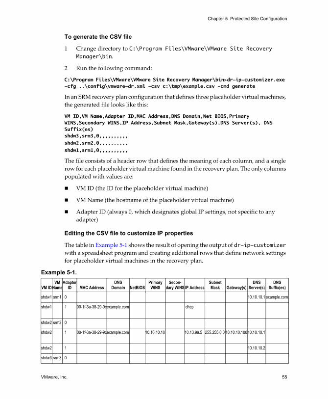
VMware, Inc. 55
Chapter 5 Protected Site Configuration
To generate the CSV file
1 Change directory to C:\Program Files\VMware\VMware Site Recovery Manager\bin.
2 Run the following command:
C:\Program Files\VMware\VMware Site Recovery Manager\bin>dr-ip-customizer.exe -cfg ..\config\vmware-dr.xml -csv c:\tmp\example.csv -cmd generate
In an SRM recovery plan configuration that defines three placeholder virtual machines, the generated file looks like this:
VM ID,VM Name,Adapter ID,MAC Address,DNS Domain,Net BIOS,Primary WINS,Secondary WINS,IP Address,Subnet Mask,Gateway(s),DNS Server(s), DNS Suffix(es)shdw3,srm3,0,,,,,,,,,,shdw2,srm2,0,,,,,,,,,,shdw1,srm1,0,,,,,,,,,,
The file consists of a header row that defines the meaning of each column, and a single row for each placeholder virtual machine found in the recovery plan. The only columns populated with values are:
VM ID (the ID for the placeholder virtual machine)
VM Name (the hostname of the placeholder virtual machine)
Adapter ID (always 0, which designates global IP settings, not specific to any adapter)
Editing the CSV file to customize IP properties
The table in Example 5‐1 shows the result of opening the output of dr-ip-customizer with a spreadsheet program and creating additional rows that define network settings for placeholder virtual machines in the recovery plan.
Example 5-1.
VM IDVM
NameAdapter
ID MAC AddressDNS
Domain NetBIOSPrimary
WINSSecon-
dary WINS IP AddressSubnet Mask Gateway(s)
DNS Server(s)
DNS Suffix(es)
shdw1 srm1 0 10.10.10.1 example.com
shdw1 1 00-1f-3a-38-29-9cexample.com dhcp
shdw2 srm2 0
shdw2 1 00-1f-3a-38-29-9cexample.com 10.10.10.10 10.13.99.5 255.255.0.0 10.10.10.10010.10.10.1
shdw2 1 10.10.10.2
shdw3 srm3 0
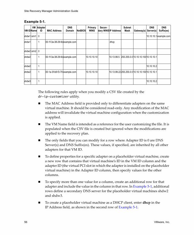
Site Recovery Manager Administration Guide
56 VMware, Inc.
The following rules apply when you modify a CSV file created by the dr-ip-customizer utility.
The MAC Address field is provided only to differentiate adapters on the same virtual machine. It should be considered read‐only. Any modification of the MAC address will invalidate the virtual machine configuration when the customization is applied.
The VM Name field is intended as a reference for the user customizing the file. It is populated when the CSV file is created but ignored when the modifications are applied to the recovery plan.
The only fields that you can modify for a row where Adapter ID is 0 are DNS Server(s) and DNS Suffix(es). These values, if specified, are inherited by all other adapters for that VM ID.
To define properties for a specific adapter on a placeholder virtual machine, create a new row that contains that virtual machine’s ID in the VM ID column and the adapter ID (the virtual PCI slot in which the adapter is installed on the placeholder virtual machine) in the Adapter ID column, then specify values for the other columns.
To specify more than one value for a column, create an additional row for that adapter and include the value in the column in that row. In Example 5‐1, additional rows define a secondary DNS server for the placeholder virtual machines shdw2 and shdw3.
To create a placeholder virtual machine as a DHCP client, enter dhcp in the IPAddress field, as shown in the second row of Example 5‐1.
shdw2 1 00-1a-3f-b8-f3-79 example.com 10.10.10.10 10.13.99.22 255.255.0.0 10.10.10.10010.10.10.1
shdw3 1 10.10.10.2
Example 5-1.
VM IDVM
NameAdapter
ID MAC AddressDNS
Domain NetBIOSPrimary
WINSSecon-
dary WINS IP AddressSubnet Mask Gateway(s)
DNS Server(s)
DNS Suffix(es)
shdw1 srm1 0 10.10.10.1 example.com
shdw1 1 00-1f-3a-38-29-9cexample.com dhcp
shdw2 srm2 0
shdw2 1 00-1f-3a-38-29-9cexample.com 10.10.10.10 10.13.99.5 255.255.0.0 10.10.10.10010.10.10.1
shdw2 1 10.10.10.2
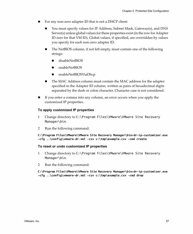
VMware, Inc. 57
Chapter 5 Protected Site Configuration
For any non‐zero adapter ID that is not a DHCP client:
You must specify values for IP Address, Subnet Mask, Gateway(s), and DNS Server(s) unless global values for these properties exist (in the row for Adapter ID zero for that VM ID). Global values, if specified, are overridden by values you specify for each non‐zero adapter ID.
The NetBIOS column, if not left empty, must contain one of the following strings:
disableNetBIOS
enableNetBIOS
enableNetBIOSViaDhcp
The MAC Address column must contain the MAC address for the adapter specified in the Adapter ID column, written as pairs of hexadecimal digits separated by the dash or colon character. Character case is not considered.
If you enter a comma into any column, an error occurs when you apply the customized IP properties.
To apply customized IP properties
1 Change directory to C:\Program Files\VMware\VMware Site Recovery Manager\bin.
2 Run the following command:
C:\Program Files\VMware\VMware Site Recovery Manager\bin>dr-ip-customizer.exe -cfg ..\config\vmware-dr.xml -csv c:\tmp\example.csv -cmd create
To reset or undo customized IP properties
1 Change directory to C:\Program Files\VMware\VMware Site Recovery Manager\bin.
2 Run the following command:
C:\Program Files\VMware\VMware Site Recovery Manager\bin>dr-ip-customizer.exe -cfg ..\config\vmware-dr.xml -csv c:\tmp\example.csv -cmd drop
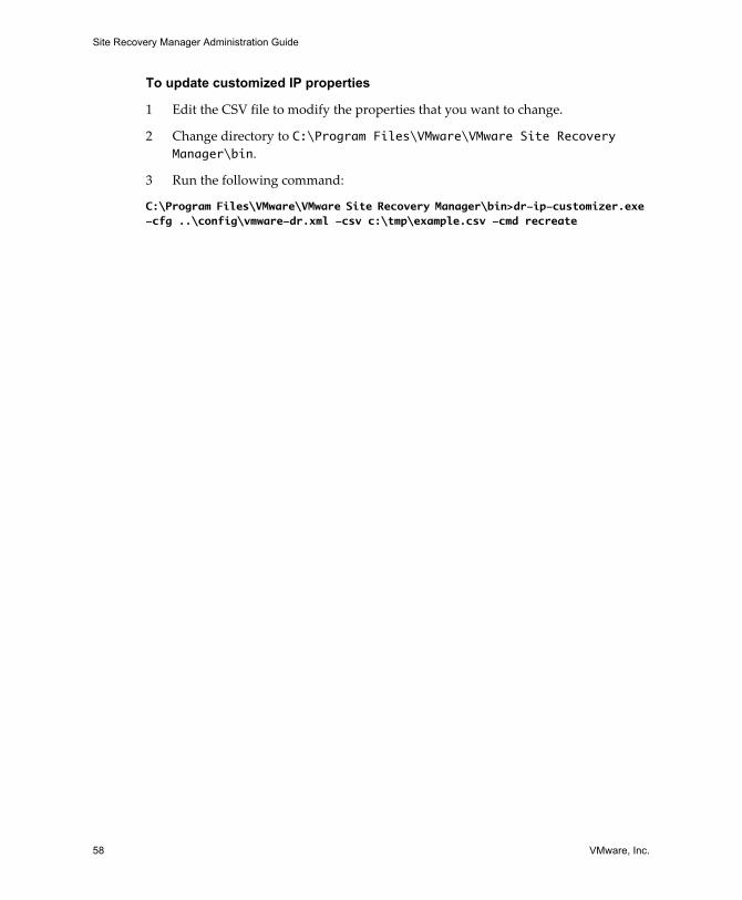
Site Recovery Manager Administration Guide
58 VMware, Inc.
To update customized IP properties
1 Edit the CSV file to modify the properties that you want to change.
2 Change directory to C:\Program Files\VMware\VMware Site Recovery Manager\bin.
3 Run the following command:
C:\Program Files\VMware\VMware Site Recovery Manager\bin>dr-ip-customizer.exe -cfg ..\config\vmware-dr.xml -csv c:\tmp\example.csv -cmd recreate
VMware, Inc. 59
6
A recovery plan is a list of steps for switching operation of your datacenter from the protected site to the recovery site. This chapter describes the steps required to create and modify recovery plans.
Configuring protection at the recovery site includes the following tasks:
Create a recovery plan.
Choose protection groups to recover in the recovery plan.
SRM populates the recovery plan with appropriate recovery steps. Customize the recovery plan as needed.
This chapter includes the following topics:
“Create a Recovery Plan” on page 60
“Managing Recovery Plans” on page 61
“Test a Recovery Plan” on page 63
“Run a Recovery Plan” on page 64
“Configure Virtual Machines in a Recovery Plan” on page 65
“Work with Customization Specifications” on page 67
Recovery Site Configuration 6
Site Recovery Manager Administration Guide
60 VMware, Inc.
Create a Recovery PlanRecovery plans are created with a Recovery Plan wizard that prompts you for a plan name and the protection groups to include in the plan. With SRM recovery plans, you can:
Create more than one recovery plan. For example, you can specify one plan for whole site failures, others for large, partial failures, or you may want one recovery plan for each business unit.
Include the same protection group in more than one recovery plan.
Create empty recovery plans for testing.
For more information, see “Create a Protection Group” on page 48.
During recovery plan creation, you choose which virtual machines to suspend during recovery. The virtual machines that are suspended are the local virtual machines that run on the recovery host. Suspending noncritical resources saves space and frees CPU and memory resources on hosts.
The machines that are powered on are the machines that are being failed over. When the recovery runs, the virtual machines power on depending on the response times set in the plan. Virtual machines can be categorized as High, Normal, Low, or No Power On so that they start in the correct order when the plan runs.
To create a recovery plan, the following conditions must be in place:
The VI Client must be connected to the recovery site.
The role of Recovery Plans Administrator.
To create a recovery plan
1 Using the VI Client, log in to the recovery site VirtualCenter Server.
2 Click Site Recovery on the VI Client toolbar.
3 Click Recovery Plans in the Inventory list.
4 In the Commands pane on the Summary tab, click Create Recovery Plan.
5 Enter a name and an optional description for the recovery plan and click Next.
6 Select the protection groups to include in the plan and click Next.
You can include one or more protection groups in a recovery plan.

VMware, Inc. 61
Chapter 6 Recovery Site Configuration
7 Set the response times for the virtual machines in the plan (responses cannot be detected on virtual machines that do not have VMware Tools installed).
Change Network Settings: If the virtual machine does not acquire the expected IP address within the specified interval after a recovery step that changes network settings, an error is reported and the recovery plan proceeds to the next virtual machine.
Wait for OS Heartbeat: If the virtual machine does not report an OS heartbeat within the specified interval after being powered on, an error is reported and the recovery plan proceeds to the next virtual machine.
8 Click Next.
9 Select the network to use during recovery plan tests, or select Auto to create an isolated network from the Test Network drop‐down menu.
If the recovery plan includes virtual machines that run Linux and are DHCP clients, be sure that the test network includes a DHCP server.
If your VI cluster at the recovery site uses VMware HA, you must create and use use a test VLAN that spans ESX hosts. HA clusters do not work correctly on other test network configurations.
10 Click Next.
11 Expand Virtual Machines and the Datacenter.
12 Select the local virtual machines to suspend when the plan is tested or run, and click Finish.
Managing Recovery PlansWhen you select a recovery plan in the navigation pane, your recovery plan details appear in the main viewing area of the page. The following tabs appear on the page:
Summary—Provides a summary of the recovery plan, including name, description, and commands you can run for the plan, such as editing or testing the plan. The summary tab is the default.
Virtual Machines—Displays the virtual machines that this recovery plan protects.
Recovery Steps—Lists the steps of the recovery plan.
History—Displays whether the recovery plan was run, the date when it ran, the duration of the run, the status, and the results of the plan. Provides an option to export a copy of the results in XML, HTML, or CSV formats.
Permissions—Lists the users who are authorized to maintain the recovery plan.
Site Recovery Manager Administration Guide
62 VMware, Inc.
When you select a recovery plan in the navigation pane, the following commands appear on the Summary tab:
Edit Recovery Plan—Modify the plan name and description, protection groups that are included in the plan, virtual machine response times, network to use during plan testing, and local machines to be suspended as part of the recovery plan.
Remove Recovery Plan—Delete the recovery plan.
Test Recovery Plan—Run a test of the recovery plan.
Run Recovery Plan—Run the recovery plan.
Edit a Recovery PlanYou can modify the plan name and description, protection groups that are included in the plan, virtual machine response times, network to use during plan testing, local machines to be suspended as part of the recovery plan, and messages and commands.
To edit a recovery plan, the following conditions must be in place:
The VI Client must be connected to the recovery site.
The role of Recovery Plans Administrator.
To edit a recovery plan
1 On the Summary tab, click Edit Recovery Plan.
2 Modify the plan name or description and click Next.
3 Modify the protection groups included in the recovery site if needed and click Next.
4 Modify the response times for the virtual machines in the recovery plan if needed and click Next.
5 Modify the networks you originally specified for testing the plan.
When you are finished, click Next.
6 Modify the local virtual machines to suspend if a recovery occurs or during a recovery test.
7 Click Finish.
The recovery plan is modified. When you select the plan again in the Inventory, your changes are reflected in the Summary tab, History tab, and Recovery Steps tab.
VMware, Inc. 63
Chapter 6 Recovery Site Configuration
Test a Recovery PlanYou can run frequent tests, which simulate an actual recovery. You can run test recoveries and edit the recovery plan to fix any problems when you run the tests. SRM runs exactly the same plan that is run for both tests and actual recoveries with the following exceptions:
Recovery tests do not connect to the protected site and shut down virtual machines.
Recovery tests create test networks so that the infrastructure of the protection and recovery site is protected. The test network is removed after the test is completed. This action ensures that the infrastructure of both sites is protected. You can, however, select an actual network to test recovery.
The virtual machines in the recovery site typically start from a datastore that is cloned from the target datastore in the recovery site to ensure that the test is run against a storage infrastructure that is isolated from the production environment.
To test a recovery plan, the following conditions must be in place:
The VI Client must be connected to the recovery site.
The role of Recovery Plans Administrator.
To test a recovery plan
1 In the navigation bar, select the plan to test.
2 On the Summary tab, click Test Recovery Plan.
3 Click Continue to continue the recovery test.
In the Recent Tasks area of the page (if it is open), Run Test Mode Recovery Plan appears in the Name field, and the Status field displays the percentage complete.
Pausing, Resuming, or Cancelling a TestYou can pause, resume, or cancel a recovery plan test at any time. When you pause or cancel a test, no new steps are started, and in‐progress steps are subject to the following rules:
Steps that cannot be stopped, such as powering on or waiting for a heartbeat, run to completion before the pause or cancellation completes.
Steps that add or remove storage devices are undone by cleanup operations if you cancel or by subsequent steps if you pause and resume.
Site Recovery Manager Administration Guide
64 VMware, Inc.
The time it takes to pause or cancel a test depends on the type and number of steps that are in progress when the request is made. The time it takes to resume a test depends on the type and number of steps that were in progress when the pause was requested.
Run a Recovery PlanRunning an actual recovery plan starts the virtual machines on the recovery site on the recovery site network. This process cannot be undone easily or automatically. If you run a recovery plan, it permanently alters the virtual machines and infrastructure of the protected and recovery sites. The following changes occur if you run a recovery plan:
During a recovery, if the protected site is connected to the recovery site, virtual machines shut down gracefully on the protected site.
If the connection between sites is lost, no action is taken by SRM against the protected virtual machines in the protected site. The datastores in the recovery site are enabled for read and write capabilities and SRM initiates the power up of the virtual machines in the recovery site according to the startup order in the recovery plan.
If the connection between the sites is lost and the protected site is down, the virtual machines are already in a shut‐down state.
To run a recovery plan, the following conditions must be in place:
The VI Client must be connected to the recovery site.
The role of Recovery Plans Administrator.
To run a recovery plan
1 On the recovery site, In the Inventory, select the plan to run.
2 On the Summary tab, click Run Recovery Plan.
3 Confirm and click Run Recovery Plan.
As the plan runs, the status of each step updates on the Recovery Steps tab.
Remove a Recovery PlanRemoving a recovery plan permanently deletes the plan from SRM. You cannot retrieve a recovery plan after it is deleted.
To remove a recovery plan, the following conditions must be in place:
The VI Client must be connected to the recovery site.
The role of Recovery Plans Administrator.
VMware, Inc. 65
Chapter 6 Recovery Site Configuration
To remove a recovery plan
1 In the navigation bar, select the plan to delete.
2 On the Summary tab, click Remove Recovery Plan.
3 Click Yes to confirm and delete the plan.
Configure Virtual Machines in a Recovery PlanThe Virtual Machines tab allows you to view and configure the virtual machines that this recovery plan includes.
To configure virtual machines in a recovery plan, the following conditions must be in place:
VI Client must be connected to the recovery site.
The role of Recovery Plans Administrator.
To edit virtual machine properties in a plan
1 On the Virtual Machines tab, click Edit.
2 Click Browse to view the available customization specifications.
3 Click the arrow and select the customization property to apply to the virtual machine.
To configure this option, a customization specification must be created using the VI Client on the recovery site. If no specifications are configured, the message “No available Customization Specification found” appears.
4 Click OK.
5 Specify the default recovery priority and click Next.
Recovery priority is a property of a virtual machine, not a recovery plan. The recovery priority of a virtual machine cannot be changed after it has been made part of a recovery plan.
6 Add messages and commands, remove or reorder steps to be performed before power on.
See “Add Message and Command Steps” on page 52.
7 Click Next.
8 Add messages and commands, remove or reorder steps to be performed after power on.
9 Click Finish.
Site Recovery Manager Administration Guide
66 VMware, Inc.
View a Recovery PlanTo view a recovery plan, click the Recovery Steps tab, which lists the recommended steps for disaster recovery. Some steps might include substeps in a tree formation.
Click the plus sign (+) to expand the view to include substeps. Click the minus sign (‐) to view only high‐level steps.
In addition to recovery steps and substeps, other columns of information appear. The following information appears in the recovery plan. Some fields are empty until a recovery plan is tested or run.
Recovery Step—The steps and sub‐steps to be performed during the recovery.
Status—Blank until a recovery plan is run or tested. When a step is successfully completed, the word Success appears in the Status column.
Task Started—When a plan is run or tested, the start date and time for this step appear.
Task Completed—When a plan is tested or run, the completed date and time for this step appear.
Mode—Describes whether the step is running during a test or an actual recovery. Recovery describes steps that are running only during a recovery. If a test is running, the word Test appears and applies to tests only.
To select which information columns appear on a recovery plan
1 Right‐click the text bar.
2 Deselect the name of a column to turn off viewing for that column.
On the Recovery tab, a toolbar of icons appears. Roll the cursor over each icon to see a brief description of the icons, which enable actions such as editing or exporting your recovery plan.
To export the steps of a recovery plan
1 Click the Export icon on the Recovery Steps tab.
2 Save the file in a directory using a file name of your choice.
The report exports in XML, .doc, XLW, HTML, and CSV formats.
VMware, Inc. 67
Chapter 6 Recovery Site Configuration
View Recovery Plan HistoryAfter you test or run a recovery plan, information appears on the History tab.
To view a recovery plan
1 On the History tab, select a recovery plan and click View.
2 Click the Windows Close button when you are finished viewing the plan.
Export Recovery History ResultsUse the History tab to export a the recovery plan results.
To export a recovery plan
1 On the History tab, select the recovery plan to export and click the Export icon.
2 Enter a name for the recovery plan in the File Name field and click Save.
3 Close the Save As dialog box.
Work with Customization SpecificationsSRM uses default settings inherited from VirtualCenter such as registration information, time zone, administrator password, and IP adapter properties of the virtual machines in a recovery plan. You can update the IP adapter properties, but no other properties, of virtual machines in the plan by editing the customization specification.
To apply customization specifications to virtual machines, see “Configuring Virtual Machine Properties” on page 49.
To create a customization specification
1 From the VI Client, select Edit > Customization Specifications.
2 Select New.
3 Click Next until the Network page appears.
4 To change network settings, select Custom settings and click Next.
5 Select the name of the network to customize and click Customize.
Site Recovery Manager Administration Guide
68 VMware, Inc.
6 Make changes to the network settings and click OK.
7 Click Next and click Finish.
The script now appears on the Customization Specification Manager page and is available for use on the protected site.
8 Click the Close box.
To import a customization specification
1 Select Edit > Customization Specifications.
2 Select Import.
3 Browse for the script to import and click Open.
VMware, Inc. 69
7
Managing failback using VMware Site Recovery Manager (SRM) is a manual process that you can manage like any planned server migration. With SRM you can failback services from a recovery site to the protected site after the protects site is ready to resume operation.
This chapter includes the following topics:
“Failback Scenario” on page 69
“Other Failback Considerations” on page 74
Failback ScenarioThe following steps describe a scenario using SRM as a failback tool to Site A after these virtual machines are recovered at Site B. Six machines called app_vm7 through app_vm12 (hosted by a datastore group called shared‐san‐2) are failed back to Site A from Site B.
Figure 7‐1 illustrates the storage configuration after running a failover from Site A to Site B.
Failback 7
NOTE Consult your array vendorʹs documentation before attempting a failback. Not all arrays support the necessary operations. For more information, see the VMware Web site.
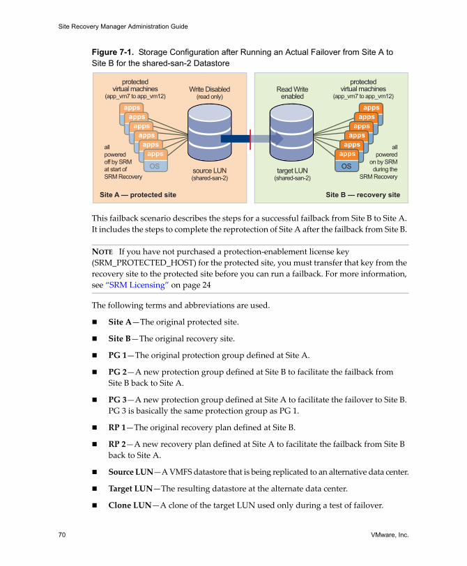
Site Recovery Manager Administration Guide
70 VMware, Inc.
Figure 7-1. Storage Configuration after Running an Actual Failover from Site A to Site B for the shared-san-2 Datastore
This failback scenario describes the steps for a successful failback from Site B to Site A. It includes the steps to complete the reprotection of Site A after the failback from Site B.
The following terms and abbreviations are used.
Site A—The original protected site.
Site B—The original recovery site.
PG 1—The original protection group defined at Site A.
PG 2—A new protection group defined at Site B to facilitate the failback from Site B back to Site A.
PG 3—A new protection group defined at Site A to facilitate the failover to Site B. PG 3 is basically the same protection group as PG 1.
RP 1—The original recovery plan defined at Site B.
RP 2—A new recovery plan defined at Site A to facilitate the failback from Site B back to Site A.
Source LUN—A VMFS datastore that is being replicated to an alternative data center.
Target LUN—The resulting datastore at the alternate data center.
Clone LUN—A clone of the target LUN used only during a test of failover.
NOTE If you have not purchased a protection‐enablement license key (SRM_PROTECTED_HOST) for the protected site, you must transfer that key from the recovery site to the protected site before you can run a failback. For more information, see “SRM Licensing” on page 24
Site A — protected site Site B — recovery site
source LUN(shared-san-2)
Write Disabled(read only)
target LUN(shared-san-2)
Read Writeenabled
protectedvirtual machines
(app_vm7 to app_vm12)
appsapps
appsapps
appsapps
OS
appsapps
appsapps
appsapps
OS
allpoweredoff by SRMat start of SRM Recovery
protectedvirtual machines
(app_vm7 to app_vm12)
allpowered
on by SRMduring the
SRM Recovery
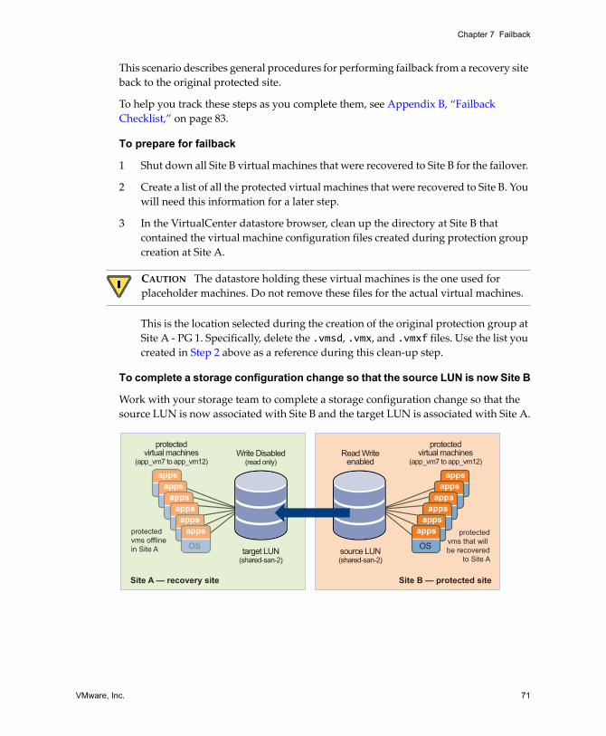
VMware, Inc. 71
Chapter 7 Failback
This scenario describes general procedures for performing failback from a recovery site back to the original protected site.
To help you track these steps as you complete them, see Appendix B, “Failback Checklist,” on page 83.
To prepare for failback
1 Shut down all Site B virtual machines that were recovered to Site B for the failover.
2 Create a list of all the protected virtual machines that were recovered to Site B. You will need this information for a later step.
3 In the VirtualCenter datastore browser, clean up the directory at Site B that contained the virtual machine configuration files created during protection group creation at Site A.
This is the location selected during the creation of the original protection group at Site A ‐ PG 1. Specifically, delete the .vmsd, .vmx, and .vmxf files. Use the list you created in Step 2 above as a reference during this clean‐up step.
To complete a storage configuration change so that the source LUN is now Site B
Work with your storage team to complete a storage configuration change so that the source LUN is now associated with Site B and the target LUN is associated with Site A.
CAUTION The datastore holding these virtual machines is the one used for placeholder machines. Do not remove these files for the actual virtual machines.
Site A — recovery site Site B — protected site
target LUN(shared-san-2)
Write Disabled(read only)
source LUN(shared-san-2)
Read Writeenabled
protectedvirtual machines
(app_vm7 to app_vm12)
appsapps
appsapps
appsapps
OS
appsapps
appsapps
appsapps
OS
protectedvms offlinein Site A
protectedvirtual machines
(app_vm7 to app_vm12)
protectedvms that will be recovered
to Site A
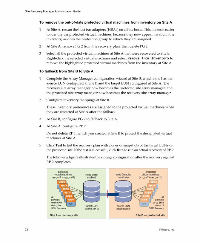
Site Recovery Manager Administration Guide
72 VMware, Inc.
To remove the out-of-date protected virtual machines from inventory on Site A
1 At Site A, rescan the host bus adapters (HBAs) on all the hosts. This makes it easier to identify the protected virtual machines, because they now appear invalid in the inventory, as does the protection group to which they are assigned.
2 At Site A, remove PG 2 from the recovery plan, then delete PG 2.
3 Select all the protected virtual machines at Site A that were recovered to Site B. Right‐click the selected virtual machines and select Remove from Inventory to remove the highlighted protected virtual machines from the inventory at Site A.
To failback from Site B to Site A
1 Complete the Array Manager configuration wizard at Site B, which now has the source LUN configured at Site B and the target LUN configured at Site A. The recovery site array manager now becomes the protected site array manager, and the protected site array manager now becomes the recovery site array manager.
2 Configure inventory mappings at Site B.
These inventory preferences are assigned to the protected virtual machines when they are restarted at Site A after the failback.
3 At Site B, configure PG 2 to failback to Site A.
4 At Site A, configure RP 2.
Do not delete RP 1, which you created at Site B to protect the designated virtual machines at Site A.
5 Click Test to test the recovery plan with clones or snapshots of the target LUNs on the protected site. If the test is successful, click Run to run an actual recovery of RP 2.
The following figure illustrates the storage configuration after the recovery against RP 2 completes.
Site A — recovery site Site B — protected site
target LUN(shared-san-2)
source LUN(shared-san-2)
Write Disabled(read only)
Read Writeenabled
protectedvirtual machines
(app_vm7 to app_vm12)
appsapps
appsapps
appsapps
OS
appsapps
appsapps
appsapps
OS
allpoweredon by SRMduring theSRM Recovery
protectedvirtual machines
(app_vm7 to app_vm12)
allpowered
off by SRMat start of
SRM Recovery
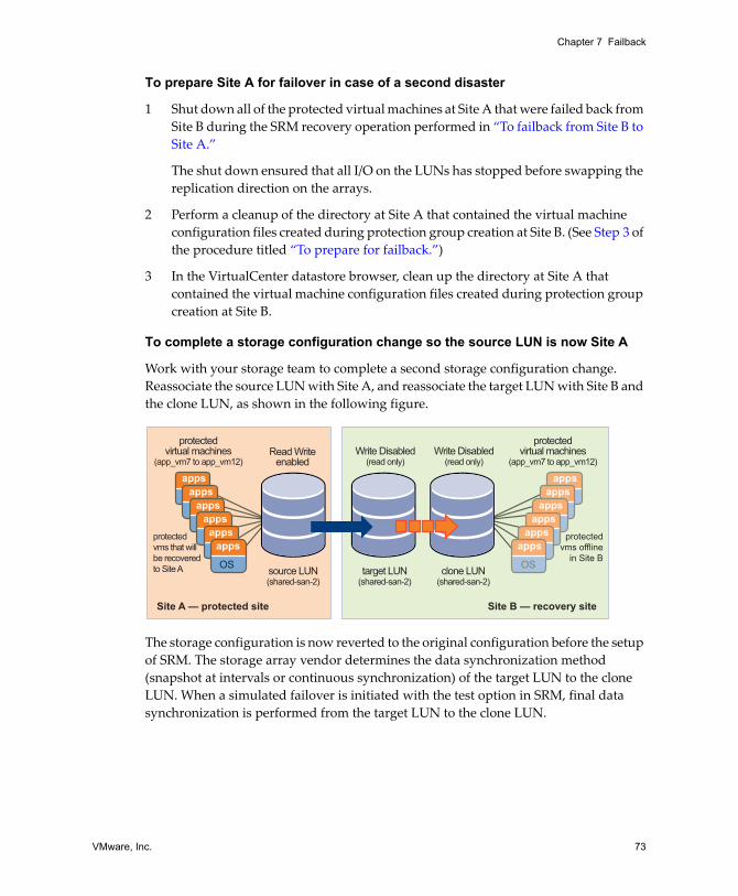
VMware, Inc. 73
Chapter 7 Failback
To prepare Site A for failover in case of a second disaster
1 Shut down all of the protected virtual machines at Site A that were failed back from Site B during the SRM recovery operation performed in “To failback from Site B to Site A.”
The shut down ensured that all I/O on the LUNs has stopped before swapping the replication direction on the arrays.
2 Perform a cleanup of the directory at Site A that contained the virtual machine configuration files created during protection group creation at Site B. (See Step 3 of the procedure titled “To prepare for failback.”)
3 In the VirtualCenter datastore browser, clean up the directory at Site A that contained the virtual machine configuration files created during protection group creation at Site B.
To complete a storage configuration change so the source LUN is now Site A
Work with your storage team to complete a second storage configuration change. Reassociate the source LUN with Site A, and reassociate the target LUN with Site B and the clone LUN, as shown in the following figure.
The storage configuration is now reverted to the original configuration before the setup of SRM. The storage array vendor determines the data synchronization method (snapshot at intervals or continuous synchronization) of the target LUN to the clone LUN. When a simulated failover is initiated with the test option in SRM, final data synchronization is performed from the target LUN to the clone LUN.
Site A — protected site Site B — recovery site
source LUN(shared-san-2)
clone LUN(shared-san-2)
Write Disabled(read only)
target LUN(shared-san-2)
Write Disabled(read only)
Read Writeenabled
protectedvirtual machines
(app_vm7 to app_vm12)
appsapps
appsapps
appsapps
OS
appsapps
appsapps
appsapps
OS
protectedvms that willbe recoveredto Site A
protectedvirtual machines
(app_vm7 to app_vm12)
protectedvms offline
in Site B
Site Recovery Manager Administration Guide
74 VMware, Inc.
To prepare Site B for failover in case of a second disaster
1 At Site B, rescan the host bus adapters (HBAs) on all the hosts. This makes it easier to identify the protected virtual machines, because they now appear invalid in the inventory, as does the protection group to which they are assigned.
2 At Site B, remove PG2 from the recovery plan, then delete PG 2.
3 At Site B, remove all the protected virtual machines that were recovered to Site A from inventory at Site B. In this scenario, this is app_vm7 to app_vm12. (See “To remove the out‐of‐date protected virtual machines from inventory on Site A.”)
4 Create PG 3 at Site A for the protected virtual machines.
PG 3 should be identical to PG 1, the protection group that was originally associated with RP 1, the recovery plan that was run in Recovery mode and resulted in the startup of the protected virtual machines at Site B.
5 Reassociate the protection groups at Site A with RP 1 at Site B.
You do not need to delete RP 2 (the recovery plan that was created at Site A to facilitate the recovery back to Site A from Site B).
You have completed the reprotection of the protected virtual machines at Site A. VMware recommends that you now conduct a failover test against RP 1 to ensure that Site A is protected and ready for any event that may necessitate a recovery to Site B if another disaster occurs.
Other Failback ConsiderationsThere are several more issues to consider during a failback.
Site Pairing—Sites A and B need to be paired only once. SRM maintains a bidirectional relationship between paired sites.
DNS Updates—If Site A and Site B are not joined by a stretched VLAN, manually provide DNS updates as the virtual machines are moved between Site A and Site B and their IP addresses change to accommodate their new network.
VMware, Inc. 75
8
This chapter describes Site Recovery Manager (SRM) events and alarm notification configuration options. This chapter includes the following topics:
“SRM Alarms” on page 75
“About SRM Alarm Triggers” on page 76
“Edit SRM Alarm Settings” on page 76
“Prepare for Alarm Notification by Email” on page 78
SRM AlarmsSRM alarms are notifications that occur in response to selected events that SRM raises. These event‐triggered alarms are available and configured when Site Recovery is selected in the VI Client. The alarms specific to SRM events are defined when SRM is installed.
SRM alarms use email message notification. For information about how to configure a VirtualCenter Server to support email message alarm notification before you edit SRM alarms, see “Prepare for Alarm Notification by Email” on page 78.
The Alarms tab in the Site Recovery view displays the list of alarms for SRM that are activated when designated events occur. These alarms are SRM specific and are not available from the VirtualCenter Server. (SRM alarms do not appear in the VI Clientʹs Triggered Alarms pane, though they are shown in the Virtual Center Event Log.)
Alerting and Monitoring 8
NOTE SRM alarms for any event do not trigger more than once every five minutes. Multiple instances of the same event during a five‐minute period trigger only a single alarm.
Site Recovery Manager Administration Guide
76 VMware, Inc.
About SRM Alarm TriggersAlarm triggers take several forms:
SRM generates events that can be associated with alarms on the VirtualCenter Server, such as:
Problems on the SRM server generate SNMP traps, emails, and so on.
Alarms are associated with SRM events from the SRM plug‐in.
Failure of the SRM server or VirtualCenter server at the protected or recovery site generates events that can be associated with VirtualCenter alarms, such as:
Problems with the local site (for example, resource constraints).
Problems with the remote site (for example, being unable to ping the SRM or VirtualCenter host at a remote site). Remote‐site failure is reflected in the SRM events and does not trigger a recovery. Recovery must be initiated manually.
Disk space is low.
CPU use exceeded the limit.
Memory is low.
The remote site fails to respond.
The VirtualCenter Server or SRM server at the remote site fails.
The recovery test started, ended successfully, failed, or is cancelled.
Virtual machine recovery started, ended, succeeded, failed, or reports a warning.
The following are the alarm notification methods:
Send a notification email message
Send a notification trap
Run a script
Edit SRM Alarm SettingsYou can modify SRM alarms. A simple change is to enable or disable the alarm. If an alarm is disabled, an X appears on the alarm listing icon.
To edit an SRM alarm, the following conditions must be in place:
VI Client must be connected to the protection or recovery site.
The minimum required privileges are Modify Alarm (Alarms privileges).
VMware, Inc. 77
Chapter 8 Alerting and Monitoring
To edit an alarm
1 Using a VI Client, log in to the protected site VirtualCenter Server.
2 Click Site Recovery on the VI Client toolbar.
3 Click the Alarms tab.
4 Right‐click the event and select Edit Settings.
5 Click Action to choose the action to take when the event is triggered and specify the associated information.
6 To complete the alarm, click OK.
7 VirtualCenter verifies the configuration of the alarm and adds the alarm to the list of alarms for SRM.
Option Description
Send a notification email
Provide the email address of the notification recipient in the Value field. SMTP sends a notification email. SMTP must be ready when the email is sent. The VirtualCenter Server generates the email message subject and body text. Only the “to” list (Value) is required from user input. Specify the email address to which the message should be sent. For information about preparing for email message SMTP alarm notification for VirtualCenter Server, see the VMware Infrastructure Basic System Administration.
Send a notification trap
The VirtualCenter Server is a default SNMP notification receiver. An SNMP trap viewer is required to view a sent trap. The VirtualCenter Server host must be configured to receive SNMP traps. For information about preparing for email message SNMP alarm SMTP alarm notification for VirtualCenter Server, see VMware Infrastructure Basic System Administration.
Run a script If the script is an .exe file, provide the path to the script. If the script is a .bat file, provide the script path as an argument to the c:\windows\system32\cmd.exe command. For example, to run a script located in c:\alarmscript.bat, provide the script path as c:\windows\system32\cmd.exe /c c:\alarmscript.cmd.
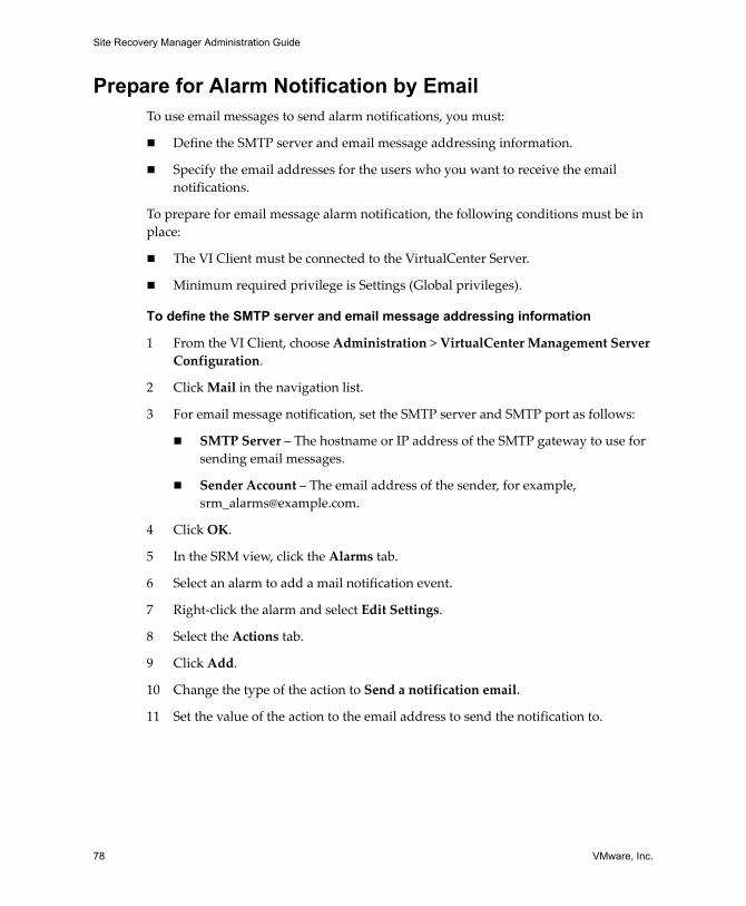
Site Recovery Manager Administration Guide
78 VMware, Inc.
Prepare for Alarm Notification by EmailTo use email messages to send alarm notifications, you must:
Define the SMTP server and email message addressing information.
Specify the email addresses for the users who you want to receive the email notifications.
To prepare for email message alarm notification, the following conditions must be in place:
The VI Client must be connected to the VirtualCenter Server.
Minimum required privilege is Settings (Global privileges).
To define the SMTP server and email message addressing information
1 From the VI Client, choose Administration > VirtualCenter Management Server Configuration.
2 Click Mail in the navigation list.
3 For email message notification, set the SMTP server and SMTP port as follows:
SMTP Server – The hostname or IP address of the SMTP gateway to use for sending email messages.
Sender Account – The email address of the sender, for example, [email protected].
4 Click OK.
5 In the SRM view, click the Alarms tab.
6 Select an alarm to add a mail notification event.
7 Right‐click the alarm and select Edit Settings.
8 Select the Actions tab.
9 Click Add.
10 Change the type of the action to Send a notification email.
11 Set the value of the action to the email address to send the notification to.
VMware, Inc. 79
9
SRM monitors and handles changes to the VirtualCenter Server at the protected and recovery sites.
This chapter includes the following topics:
“Changes to VirtualCenter Server” on page 79
“Changes to Protected Sites” on page 79
“Changes to Recovery Sites” on page 80
Changes to VirtualCenter ServerThe SRM servers depend on the availability of certain inventory objects, such as virtual machines and networks. Changes to the VirtualCenter Server state can affect SRM.
Renaming and relocating objects in the VirtualCenter Server inventory does not affect SRM unless it causes resources to become inaccessible during test or recovery.
Changes to Protected SitesSRM supports the following changes at the protected site without disruption:
Modifying protected virtual machine configuration, such as adding, modifying, removing devices, or relocating virtual machines.
Changing a virtual machine’s memory size on the protected site is not reflected on the recovery site if the virtual machine is already in a protection group.
Deleting protected virtual machines.
Deleting an object for which an inventory mapping exists.
Protected and Recovery Site Changes 9
Site Recovery Manager Administration Guide
80 VMware, Inc.
SRM requires reinstallation of SRM at the protected and recovery sites:
The VirtualCenter Server is reinstalled at the protected site, reinitializing the VirtualCenter database.
SRM is reinstalled at the protected site, reinitializing the SRM database.
Changes to Recovery SitesSRM supports the following changes at the recovery site without disruption:
Deleting recovery virtual machines.
Moving recovery virtual machines to a different folder, resource pool, or network.
Deleting an object for which an inventory mapping exists.
The VirtualCenter Server is reinstalled at the recovery site (re‐initializing the VirtualCenter database).
SRM requires reinstallation of SRM at the protected and recovery sites if SRM is reinstalled at the recovery site (reinitializing the SRM database).
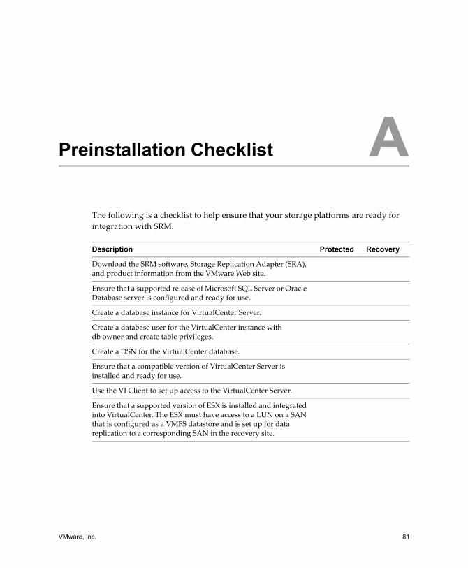
VMware, Inc. 81
The following is a checklist to help ensure that your storage platforms are ready for integration with SRM.
Preinstallation Checklist ADescription Protected Recovery
Download the SRM software, Storage Replication Adapter (SRA), and product information from the VMware Web site.
Ensure that a supported release of Microsoft SQL Server or Oracle Database server is configured and ready for use.
Create a database instance for VirtualCenter Server.
Create a database user for the VirtualCenter instance with db owner and create table privileges.
Create a DSN for the VirtualCenter database.
Ensure that a compatible version of VirtualCenter Server is installed and ready for use.
Use the VI Client to set up access to the VirtualCenter Server.
Ensure that a supported version of ESX is installed and integrated into VirtualCenter. The ESX must have access to a LUN on a SAN that is configured as a VMFS datastore and is set up for data replication to a corresponding SAN in the recovery site.
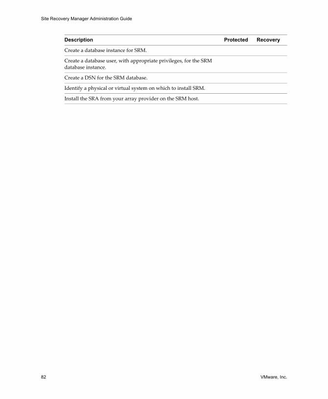
Site Recovery Manager Administration Guide
82 VMware, Inc.
Create a database instance for SRM.
Create a database user, with appropriate privileges, for the SRM database instance.
Create a DSN for the SRM database.
Identify a physical or virtual system on which to install SRM.
Install the SRA from your array provider on the SRM host.
Description Protected Recovery
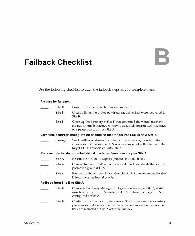
VMware, Inc. 83
Use the following checklist to track the failback steps as you complete them.
Failback Checklist BPrepare for failback
_____ Site B Power down the protected virtual machines.
_____ Site B Create a list of the protected virtual machines that were recovered to Site B.
_____ Site B Clean up the directory at Site B that contained the virtual machine configuration files created when you assigned the protected machines to a protection group on Site A.
Complete a storage configuration change so that the source LUN is now Site B
_____ Storage Work with your storage team to complete a storage configuration change so that the source LUN is now associated with Site B and the target LUN is associated with Site A.
Remove out-of-date protected virtual machines from inventory on Site A
_____ Site A Rescan the host bus adapters (HBAs) on all the hosts.
_____ Site A Connect to the VirtualCenter instance at Site A and delete the original protection group (PG 2).
_____ Site A Remove all the protected virtual machines that were recovered to Site B from the inventory at Site A.
Failback from Site B to Site A
_____ Site B Complete the Array Manager configuration wizard at Site B, which now has the source LUN configured at Site B and the target LUN configured at Site A.
_____ Site B Configure the inventory preferences at Site B. These are the inventory preferences that are assigned to the protected virtual machines when they are restarted at Site A after the failback.
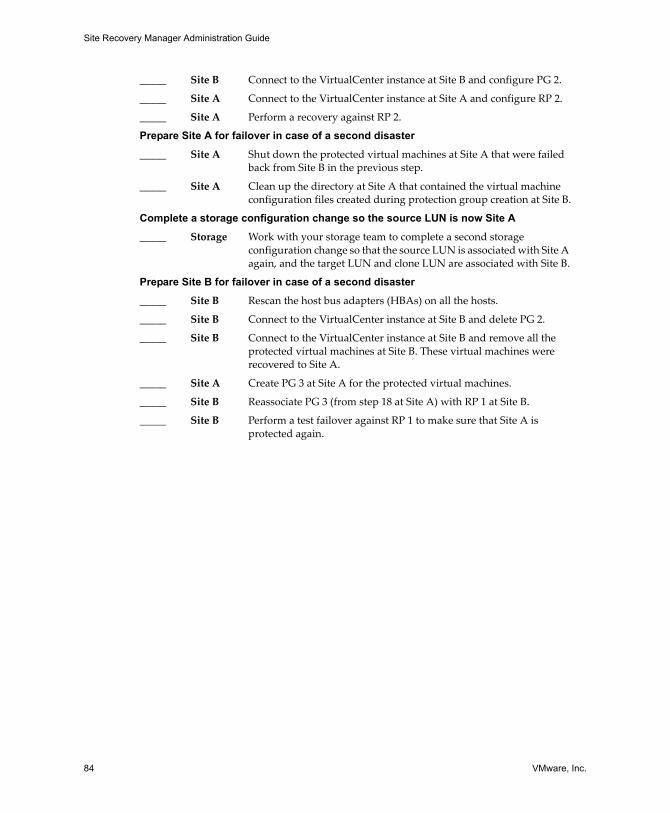
Site Recovery Manager Administration Guide
84 VMware, Inc.
_____ Site B Connect to the VirtualCenter instance at Site B and configure PG 2.
_____ Site A Connect to the VirtualCenter instance at Site A and configure RP 2.
_____ Site A Perform a recovery against RP 2.
Prepare Site A for failover in case of a second disaster
_____ Site A Shut down the protected virtual machines at Site A that were failed back from Site B in the previous step.
_____ Site A Clean up the directory at Site A that contained the virtual machine configuration files created during protection group creation at Site B.
Complete a storage configuration change so the source LUN is now Site A
_____ Storage Work with your storage team to complete a second storage configuration change so that the source LUN is associated with Site A again, and the target LUN and clone LUN are associated with Site B.
Prepare Site B for failover in case of a second disaster
_____ Site B Rescan the host bus adapters (HBAs) on all the hosts.
_____ Site B Connect to the VirtualCenter instance at Site B and delete PG 2.
_____ Site B Connect to the VirtualCenter instance at Site B and remove all the protected virtual machines at Site B. These virtual machines were recovered to Site A.
_____ Site A Create PG 3 at Site A for the protected virtual machines.
_____ Site B Reassociate PG 3 (from step 18 at Site A) with RP 1 at Site B.
_____ Site B Perform a test failover against RP 1 to make sure that Site A is protected again.
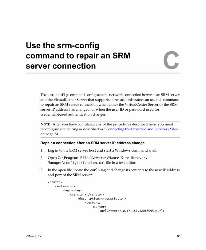
VMware, Inc. 85
The srm-config command configures the network connection between an SRM server and the VirtualCenter Server that supports it. An administrator can use this command to repair an SRM server connection when either the VirtualCenter Server or the SRM server IP address has changed, or when the user ID or password used for credential‐based authentication changes.
Repair a connection after an SRM server IP address change
1 Log in to the SRM server host and start a Windows command shell.
2 Open C:\Program Files\VMware\VMware Site Recovery Manager\config\extension.xml file in a text editor.
3 In the open file, locate the <url> tag and change its contents to the new IP address and port of the SRM server:
<config><extension>
<key></key><version></version>
<description></description><servers>
<server><url>http://10.17.186.120:8095</url>
Use the srm-config command to repair an SRM server connection C
NOTE After you have completed any of the procedures described here, you must reconfigure site pairing as described in “Connecting the Protected and Recovery Sites” on page 34.
Site Recovery Manager Administration Guide
86 VMware, Inc.
4 Change directory to C:\Program Files\VMware\VMware Site Recovery Manager\bin.
5 Run the following command to update the extension registration:
C:\Program Files\VMware\VMware Site Recovery Manager\bin>srm-config.exe -cmd updateext -cfg ..\config\vmware-dr.xml -extcfg ..\config\extension.xml
Repair a connection after a Virtual Center server IP address change
1 Log in to the SRM server host and start a Windows command shell.
2 Change directory to C:\Program Files\VMware\VMware Site Recovery Manager\bin.
3 Run the following command, where <vc‐ip‐addr> is the IP address of the Virtual Center host:
C:\Program Files\VMware\VMware Site Recovery Manager\bin>srm-config.exe -cmd updatevc -cfg ..\config\vmware-dr.xml -vc <vc-ip-addr>
If that command returns an error indicating that the certificate is not trusted, run the following command, where <vc‐ip‐addr> is the IP address of the Virtual Center host and <thumbprint‐string> is the thumbprint string returned in the error message:
C:\Program Files\VMware\VMware Site Recovery Manager\bin>srm-config.exe -cmd updatevc -cfg ..\config\vmware-dr.xml -vc <vc-ip-addr> -thumbprint <thumbprint-string>
Reinitializing credential-based authentication after a user ID or password change
1 Log in to the SRM server host and start a Windows command shell.
2 Change directory to C:\Program Files\VMware\VMware Site Recovery Manager\bin
3 Run the following command to update the user ID and password, supplying the new <userID> on the command line and the password when prompted:
C:\Program Files\VMware\VMware Site Recovery Manager\bin>srm-config.exe -cmd updateuser -cfg ..\config\vmware-dr.xml -u <userID>
VMware, Inc. 87
While SRM allows you to replicate transient data such as Windows paging files or virtual machine swapfiles, such data need not be replicated. Preventing replication of such data avoids unnecessary consumption of network bandwidth.
Specify a Nonreplicated Datastore for SwapfilesEvery virtual machine requires a swapfile, which is normally created in the same datastore as the other virtual machine files. When you use SRM, this datastore is replicated. To prevent swapfiles from being replicated, create them on a nonreplicated datastore. This procedure must be carried out for all protected clusters, at both the protected and recovery sites. For more information, see the VMware Infrastructure documentation.
To create swapfiles on a nonreplicated datastore (ESX 3.5)
1 In the VI Client, right‐click an ESX cluster and click Edit Settings.
2 In the Settings window for the cluster, click Swapfile Location and select Store the swapfile in the datastore specified by the host, then click OK.
3 For each virtual machine in the cluster:
a Click the Configuration tab.
b Click Edit on the Swapfile location line.
c In the Virtual Machine Swapfile Location window, select a nonreplicated datastore and click OK.
Avoiding Replication of Paging Files and Other Transient Data D
Site Recovery Manager Administration Guide
88 VMware, Inc.
To create swapfiles on a nonreplicated datastore (ESX 3.0.2)
1 In the selected cluster, pick a virtual machine and shut it down.
2 Make a backup copy of the virtual machine’s .vmx file.
3 Edit the .vmx file to change the value of the sched.swap.dir parameter to specify the pathname of a nonreplicated data store at the protected site.
A datastore with this pathname must also exist at the recovery site. If it does not, the virtual machine cannot power on at the recovery site.
4 Edit the vmx file to remove the sched.swap.derivedName line.
5 Save the modified .vmx file.
6 Power on the virtual machine.
7 Repeat the procedure for each virtual machine in the cluster.
Creating a Nonreplicated Virtual Disk for Paging File Storage
In the default configuration, Windows creates its paging file on the system disk (typically C:). Paging files created in this location are always replicated when you use a replicated datastore. You can avoid replication of paging files by creating a virtual disk (.vmdk file) on a nonreplicated datastore and, on each virtual machine in a protection group, configuring Windows to create its paging file on that disk. SRM detects that any virtual machine configured this way depends on at least one nonreplicated virtual disk (the paging file disk) and removes that virtual machine from its protection group. You must explicitly designate a copy of that virtual disk file at the recovery site for the recovered virtual machine to use.
To simplify the repetition of this procedure for every virtual machine in a protection group, you can create a virtual disk file template and then clone it to provide nonreplicated paging file disks for virtual machines at both sites.
To force virtual machines to use nonreplicated paging file storage
1 At the protected site, create a temporary virtual machine.
2 On the temporary virtual machine, create a new disk.
Store the disk file in a location where you typically store virtual machine templates.
3 Power on the temporary virtual machine, then create and format a partition on the new disk.
4 Disconnect the new disk from the temporary virtual machine.
VMware, Inc. 89
Appendix D Avoiding Replication of Paging Files and Other Transient Data
5 Copy the template disk to a template folder at the recovery site.
You must copy the .vmdk file and its flat counterpart (for example, pagedisk.vmdk and pagedisk-flat.vmdk).
6 At the protected site, for each virtual machine in a protection group:
a Use the vmkfstools command to create a clone of the template disk in a nonreplicated datastore.
b Use the VI Client to connect the cloned disk to the virtual machine.
c Power on the virtual machine and assign a drive letter to the cloned disk.
d Configure the virtual machine to create its paging file on the cloned virtual disk.
e Shut down and re‐start the virtual machine so that it writes its paging file to the new location (on the cloned virtual disk).
You can delete the old, unused paging file from the system disk.
f Use the vmkfstools command to clone the template you copied in Step 5 to a .vmdk file on a nonreplicated datastore at the recovery site.
g Use the VI Client to view the protection group that contains the virtual machine.
Because the virtual machine uses a nonreplicated disk for its paging file, SRM notifies you that the virtual machine uses one or more devices that do not have file backings on a replicated LUN. It then removes the virtual machine from the protection group until you resolve this configuration problem.
h In the VI Client, use the Configure Storage for this VM page to assign storage for the paging file disk to the .vmdk file you cloned in Step f.
After you configure the virtual machine to use the nonreplicated disk at the protected site, SRM considers the virtual machine’s storage to be configured and returns it to the protection group.
After the changes you made at the protected site are replicated to the recovery site, you can run a test of the recovery plan to verify that the recovered virtual machines are using the nonreplicated paging file.

Site Recovery Manager Administration Guide
90 VMware, Inc.
VMware, Inc. 91
array‐based replicationReplication of virtual machines that is managed and run by the storage subsystem itself rather than from inside the virtual machines, the vmkernel, or the service console.
failbackThe process of restoring a system to its original state, following a system failure that automatically switched the computer server, system, or network to a standby server, system or network.
failoverEvent that occurs when the recovery site takes over operation in place of the protected site after the declaration of a disaster.
inventory mappingMapping between resource pools, networks, and virtual machine folders on the protected site and their destination counterparts on the recovery site.
LUN (logical unit number)An identifier for a disk volume in a storage array.
protected siteThe datacenter that contains the virtual machines for which data is being replicated to the recovery site.
protection groupA group of virtual machines that are failed over together during test and recovery.
Glossary
Site Recovery Manager Administration Guide
92 VMware, Inc.
recovery planThe necessary steps to recover protected virtual machines in their assigned protection groups according to an order of priority defined in the plan.
recovery siteThe datacenter that contains the recovery virtual machines performing work while the protected site is unavailable.
recovery virtual machineA placeholder that represents a protected virtual machine representing the virtual machines replicated from the protected site.
storage replication adapter (SRA)Software that storage vendors provide that ensures integration of storage devices with Site Recovery Manager. These vendor‐specific scripts support array discovery, replicated LUN discovery, test failover, and actual failover.
storage arrayA storage system that contains multiple disk drives.
VMware, Inc. 93VMware, Inc. 93
Index
Aalarms
defined 75defining message addressing
information 78editing 77events that trigger 76notification 75prerequisites for editing 76prerequisites for email message
SMTP notification 78API listener ports
HTTP 30SOAP 30
array managersrepairing 47
array scripts 43authentication
see secure connection 34
Bbatch file 52
Cchecklists
failback 83pre-installation 81
clones 20masking of 20
command stepsprerequisites for adding 52purpose of 52
configurationinventory preferences 47prerequisites for virtual machine pro-
tection properties 50protected site 43recovery site 59requirements for VMware
Infrastructure 44connecting protected and recovery sites
see pairing 34customization specifications 67
creating 67importing 68
Ddatabase requirements
Oracle Server 23databases
Oracle 11SQL 11
DataSourceName (DSN) 30datastore
meta data 49datastore groups
and protection groups 13directory cleanup during failback 71, 73disaster
definition of 9DNS updates 74
Eexport formats (for recovery plans) 61
Site Recovery Manager Administration Guide
94 VMware, Inc.
Ffailback
change source LUN to site A 73change source LUN to site B 71checklist 83directory cleanup 71, 73failing back from recovery to protect-
ed site 72managing 69prepare Site A for another
failover 73prepare Site B for another
failover 74preparing for 71scenario 69
features of SRM 10CPU and memory quality 11instant updates 11leveraged storage 10monitoring and alerts 11network reconfiguration 10non-disruptive tests 10predictable management 11prepared response 10
Hhost bus adapters (HBAs) 72, 74host system requirements 20HTTP port 30
Iinstallation
array requirements for 20operating systems required for
SRM 20operating systems required for SRM
plug-in 21prerequisites 28procedure 28, 31
procedure for SRM plug-in 32VMware Infrastructure requirements
for 19inventory mapping
how used 17inventory preferences
configuring 47prerequisites for configuring 47purpose of 47
Llicensing
finding more information 24license server 24SiteRecoveryManager.lic file 24VMware License Server Tools 25
listener portsHTTP 30SOAP 30
LUNclone 73masking and zoning 20replication verification 13source LUN 71target LUN 71
Mmaximums
number of connections 30response time for virtual
machines 61message steps
prerequisites for adding 52purpose of 52
meta data 49Microsoft .NET 2.0 Framework 21
Nnotification 75
VMware, Inc. 95
Index
Ooperating system
20
Ppairing 74
prerequisites for 34protected and recovery sites 34
PKCS#12 certificate file 29placeholder virtual machine
purpose of 49poweron categorization
High, Normal, Low, or No 60pre-installation checklist 81protected and recovery sites
setting up 15, 16protected site
disruptive modifications 80non-disruptive modifications 79
protection groups 13and datastore groups 13creating 48defined 16, 48on protected sites 16prerequisites for creating 48
Rrecovery plan
creating 60defined 16, 59editing 62export formats 61, 66exporting 66, 67prerequisites for creating 60prerequisites for removing 64prerequisites for running actual 64prerequisites for testing 63removing 65running actual 64, 72
testing 63, 72viewing 66viewing details 61viewing history 67
recovery sitedisruptive modifications 80non-disruptive modifications 80
Sscripts
alarm notification 77running batch file 53running DOS command 53
secure connectioncertificate based 34credential based 34
SMTP port 78SMTP server 78snapshots 20
masking of 20SNMP trap 77SOAP
port 30SRM
environment 12installation process 15requirements for using 11
SRM architecture componentsESX server 12license server 12Oracle or SQL database 12SAN 13SRM Server 12VirtualCenter Server 12VMware File System (VMFS) 13
SRM Bulk Insert feature 23default file location 23
Site Recovery Manager Administration Guide
96 VMware, Inc.
storage replication adapters 20, 43suspending virtual machines 60system requirements 20
Ttrigger events for alarms 76trusted certificate 34
VVI Client
logging into SRM from 33using to manage SRM 33
Virtual Machine File System (VMFS) 13virtual machines 16
configuring 17, 65customization settings 67mapping preferences 16poweron categorization 60prerequisites for configuring 65prioritizing for restart after
recovery 16removing from protected site
inventory 72suspending non-critical 60
VMware Infrastructureauditability 10change control 10Distributed Resource Scheduler 10encapsulation 9hardware independence 10hardware re-purposing 10how it supports SRM 9resource pools 10shared storage 9VLANs and SRM testing 10