site closure strategy model for creosote site - 9125 · wm2009 conference march 1-5, 2009, phoenix,...
TRANSCRIPT

WM2009 Conference March 1-5, 2009, Phoenix, AZ
Site Closure Strategy Model for Creosote Site - 9125
Frederic R. Coll, D.R. Gray URS Corporation
Foster Plaza 4, Suite 300 501 Holiday Drive Pittsburgh, PA 15220
ABSTRACT In conjunction with RCRA site corrective action at an active wood preserving facility, a risk-based site closure strategy was developed and incorporated the performance of a dense non-aqueous phase liquid (DNAPL) source recovery remedy, a monitored natural attenuation (MNA) remedy for dissolved phase groundwater, and institutional controls. Innovative creosote DNAPL source recovery has been undertaken at the Site since 1998. Pooled creosote DNAPL is present 90 feet below ground within a transmissive sand and gravel aquifer with a saturated thickness of approximately 80 feet. The creosote DNAPL source is situated on the property boundary of the site and has generated a ½ mile off-site dissolved phase plume, creating significant NAPL management and remedial technology verification issues. To date, over 120,000 gallons of creosote DNAPL have been recovered from the subsurface utilizing a modified circulation well technology. A mass discharge flux protocol was developed to serve as a major performance metrics for the continuation of source removal efforts and to support the application of monitored natural attenuation as an associated remedial technology for groundwater. The mass removal success has supported the MNA remedy for dissolved phase groundwater and the associated development of institutional controls. The enacted site management strategy outlines the current and future risk management activities for the Site and represents an appropriate site closure strategy for the Site. INTRODCUTION DNAPL sites represent significant remediation challenges based upon the complex composition of the DNAPL mixture, physical properties including high viscosity and relatively low density, and the typical age of DNAPL impacted sites. Consistent with numerous regulatory guidance and sound industry practice for DNAPL sites, a phased approach to characterization and remediation is fundamental. As noted in specific regulatory and industry guidance documents (USEPA, 1992; 1993a; 1993b; 1995; 1997; 2003; ITRC, 2004; Environment Agency, 2003), DNAPL site corrective action best follows a phased approach, including:
Conceptual site model (CSM) development and verification Elimination of continuing sources and exposure limitation DNAPL source delineation, containment and removal, to the extent practical Dissolved phase plume containment and restoration, to the extent practical Ensure long-term reliability of remedy through combination of control and treatment options
The remedial action program developed for the study site employed this phased strategy and leveraged available regulatory tools to achieve corrective action protective of human health and the environment. Site Background The Site occupies approximately 155 acres and is located within the City of North Little Rock, Pulaski County, Arkansas and is located approximately 1.5 miles north of the Arkansas River. Wood preserving operations were initiated at the Site in 1907. The current wood treating operations consist of the pressure treatment of railroad switch ties and bridge pilings with a creosote-oil mixture. Pentachlorophenol was used as a preservative from the early 1960s to 1982 and chromated copper arsenate (CCA) was used from
WM2009 Conference March 1-5, 2009, Phoenix, AZ
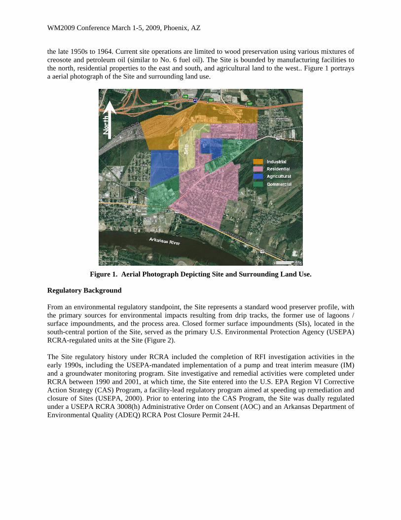
the late 1950s to 1964. Current site operations are limited to wood preservation using various mixtures of creosote and petroleum oil (similar to No. 6 fuel oil). The Site is bounded by manufacturing facilities to the north, residential properties to the east and south, and agricultural land to the west.. Figure 1 portrays a aerial photograph of the Site and surrounding land use.
Figure 1. Aerial Photograph Depicting Site and Surrounding Land Use.
Regulatory Background From an environmental regulatory standpoint, the Site represents a standard wood preserver profile, with the primary sources for environmental impacts resulting from drip tracks, the former use of lagoons / surface impoundments, and the process area. Closed former surface impoundments (SIs), located in the south-central portion of the Site, served as the primary U.S. Environmental Protection Agency (USEPA) RCRA-regulated units at the Site (Figure 2). The Site regulatory history under RCRA included the completion of RFI investigation activities in the early 1990s, including the USEPA-mandated implementation of a pump and treat interim measure (IM) and a groundwater monitoring program. Site investigative and remedial activities were completed under RCRA between 1990 and 2001, at which time, the Site entered into the U.S. EPA Region VI Corrective Action Strategy (CAS) Program, a facility-lead regulatory program aimed at speeding up remediation and closure of Sites (USEPA, 2000). Prior to entering into the CAS Program, the Site was dually regulated under a USEPA RCRA 3008(h) Administrative Order on Consent (AOC) and an Arkansas Department of Environmental Quality (ADEQ) RCRA Post Closure Permit 24-H.

WM2009 Conference March 1-5, 2009, Phoenix, AZ
Figure 2. Site Plan.
Hydrogeologic Conditions The Site is located east of the fall line between the Gulf Coastal Plain physiographic province and the Interior Highlands. The Gulf Coastal Plain includes marine and non-marine strata of Paleocene and Eocene Age, gravel of late Tertiary and Quaternary Age, and terrace deposits and alluvium of Quaternary Age. The Tertiary sediments rest unconformably on rocks of Paleozoic Age or the same rocks composing the Interior Highlands to the west (Gordon, et al., 1958). The stratigraphy beneath the Site includes Quaternary Age alluvial deposits that overlie the uppermost consolidated and indurated strata belonging to the Kincaid Formation of the Tertiary Age Midway Group (Gordon, et al., 1958). The alluvial deposit consists primarily of sand and gravel unconformably overlying the indurated confining clay layer of the Midway Group. The alluvial deposit is heterogeneous, poorly graded, and present in coarsening downward sequences. The overall thickness of the alluvial deposits overlying the confining clay layer ranges from 80 to 100 feet across the Site area. Preliminary environmental investigations arbitrarily divided the alluvium sequence into four hydrogeologic zones, the A-, B-, C-, and D-Zones (Figure 3). These zones correspond with general stratigraphical characteristics, but do not possess distinct properties that change abruptly. The approximate depths and descriptions of the zones are as follows:
A-Zone: Fill, silt, and clay with minor amounts of very fine to fine-grained sand (ground surface to approximately 20 feet below ground surface [ft-bgs]; groundwater typically present between 15 to 20 ft-bgs);
B-Zone: Fine to medium-grained sand with laterally discontinuous lenses of clay or silt that range in thickness from less than one foot to approximately six feet [20 to 45 ft-bgs];
C-Zone: Same as B-Zone except clay lenses are replaced by gravel lenses with increased grain size with depth [45 to 70 ft-bgs]; the B- and C-Zones are considered one zone and referred to as the C-Zone; and
D-Zone: Fine to coarse-grained sand and sub-rounded gravel typically less than two inches in diameter with increased grain size with depth [70 to 90 ft-bgs].

WM2009 Conference March 1-5, 2009, Phoenix, AZ
The A-, C-, and D-Zones have specific hydrogeologic properties, however the entire thickness of the alluvial deposits behave as a single, unconfined aquifer. The lower confining clay layer is very hard and has been determined to be continuous beneath the Site, ranging in thickness from eight to 30 feet. The developed CSM indicates that the direction of groundwater flow is generally to the south towards the Arkansas River in all hydrogeologic zones. Grain size and hydraulic conductivity increase with depth in the alluvial aquifer. The hydraulic gradients in each of the hydrogeologic zones are consistently on the order of 0.0004 ft/ft, while groundwater flow velocities are estimated at approximately 5 ft/yr for the A-Zone and 75-150 ft/yr for the C- and D-Zones.
Figure 3. Conceptual Diagram of Alluvial Aquifer.
A paleotopographic high on the confining layer exists near the center of the Site. The confining layer dips to the south across the Site at an approximate gradient of 0.02 ft/ft. The CSM documents the presence of a structural depression on the surface of the basally confining clay unit, situated along the southern property boundary of the Site. This area represents the main DNAPL accumulation area (i.e. trap) at the Site as upgradient DNAPL sources have migrated to this natural structural depression over time (Figure 4). Proactive remedial measures have been implemented to target DNAPL removal from this geologic trap through the use of enhanced, modified circulation well technology.
Figure 4: Perspective of DNAPL Distribution at Basal Clay.
WM2009 Conference March 1-5, 2009, Phoenix, AZ
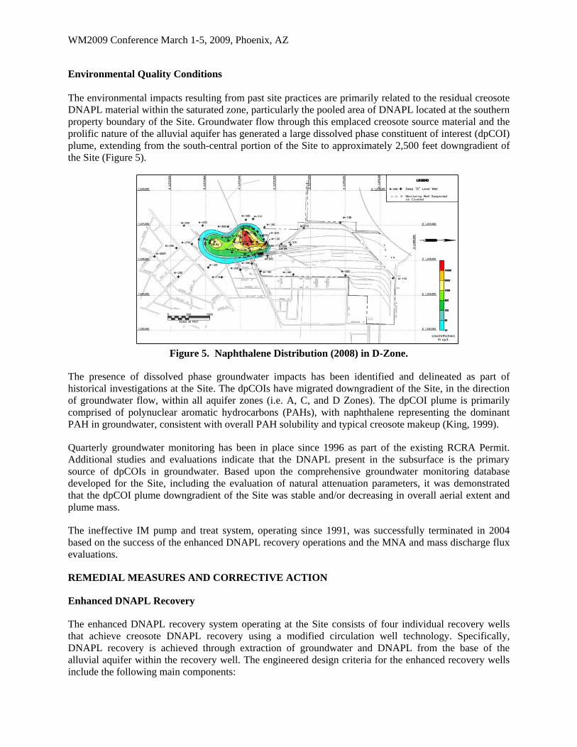
Environmental Quality Conditions The environmental impacts resulting from past site practices are primarily related to the residual creosote DNAPL material within the saturated zone, particularly the pooled area of DNAPL located at the southern property boundary of the Site. Groundwater flow through this emplaced creosote source material and the prolific nature of the alluvial aquifer has generated a large dissolved phase constituent of interest (dpCOI) plume, extending from the south-central portion of the Site to approximately 2,500 feet downgradient of the Site (Figure 5).
Figure 5. Naphthalene Distribution (2008) in D-Zone.
The presence of dissolved phase groundwater impacts has been identified and delineated as part of historical investigations at the Site. The dpCOIs have migrated downgradient of the Site, in the direction of groundwater flow, within all aquifer zones (i.e. A, C, and D Zones). The dpCOI plume is primarily comprised of polynuclear aromatic hydrocarbons (PAHs), with naphthalene representing the dominant PAH in groundwater, consistent with overall PAH solubility and typical creosote makeup (King, 1999).
Quarterly groundwater monitoring has been in place since 1996 as part of the existing RCRA Permit. Additional studies and evaluations indicate that the DNAPL present in the subsurface is the primary source of dpCOIs in groundwater. Based upon the comprehensive groundwater monitoring database developed for the Site, including the evaluation of natural attenuation parameters, it was demonstrated that the dpCOI plume downgradient of the Site was stable and/or decreasing in overall aerial extent and plume mass.
The ineffective IM pump and treat system, operating since 1991, was successfully terminated in 2004 based on the success of the enhanced DNAPL recovery operations and the MNA and mass discharge flux evaluations.
REMEDIAL MEASURES AND CORRECTIVE ACTION
Enhanced DNAPL Recovery
The enhanced DNAPL recovery system operating at the Site consists of four individual recovery wells that achieve creosote DNAPL recovery using a modified circulation well technology. Specifically, DNAPL recovery is achieved through extraction of groundwater and DNAPL from the base of the alluvial aquifer within the recovery well. The engineered design criteria for the enhanced recovery wells include the following main components:

WM2009 Conference March 1-5, 2009, Phoenix, AZ
Multiple well components in single, large diameter borehole
Maximize recovery well slot size via an engineered filter design
Target DNAPL recovery at base of aquifer as a separate phase
Achieve DNAPL recovery via gravity settling through achieving successful ratio between well diameter vs entrance velocity vs settling velocity
System process and controls operate continuously with minimal oversight
Recovered DNAPL settles into a recovery sump and the groundwater is directed to the recirculation well component of the individual recovery system, generating circulation cells in the vicinity of the recovery well, thereby enhancing the recovery of DNAPL. A schematic of the modified circulation well technology is presented as Figure 6.
Figure 6. Schematic Diagram of Enhanced Creosote DNAPL Recovery Well.
The four operating DNAPL recovery wells are strategically located in the identified areas of DNAPL accumulation or pools, located immediately downgradient of the surface impoundments and at the large DNAPL pool located at the southern property boundary of the Site (Figure 7). The individual recovery wells are designated as RW-4, RW-5, RW-6 and RW-7. Recovery well RW-4, located immediately downgradient (south) of the former Surface Impoundment, has been in operation at the Site from April 1998 through present. Enhanced DNAPL recovery well RW-5 has been in operation at the Site since May 1999 and is located along the southern property boundary of the Site, proximal to the center of the delineated DNAPL accumulation area. Recovery wells RW-6 and RW-7 were placed into service in January 2002. Through 2007, a total of 121,552 gallons of creosote DNAPL has been recovered from the subsurface by the enhanced DNAPL recovery wells.

WM2009 Conference March 1-5, 2009, Phoenix, AZ
Figure 7. Plan of Pooled Creosote DNAPL, Recovery Wells (RW) and Structural Contours of Clay.
Figure 8 presents down-well photographs taken of the enhanced DNAPL recovery well screened intervals, depicting creosote DNAPL entering the recovery well.
Figure 8. Down-well Photographs of Recovery Well Screens (100-slot) with Visible Creosote.
Natural Attenuation / Mass Discharge Flux Evaluation
Monitored Natural Attenuation (MNA) is a remedial technology in which natural subsurface processes such as dilution, volatilization, biodegradation, adsorption, and chemical reactions with subsurface materials are permitted to reduce dpCOI concentrations to acceptable levels. Consideration of MNA as a remedial option requires demonstration that natural processes of contaminant degradation will reduce contaminant concentrations below regulatory standards or risk-based levels before potential exposure pathways are completed. In addition, long term monitoring must be conducted throughout the process to confirm that degradation is proceeding at rates consistent with meeting cleanup objectives. Typically, MNA will be utilized in conjunction with active remediation measures (USEPA, 2004).
WM2009 Conference March 1-5, 2009, Phoenix, AZ
Based on the comprehensive groundwater monitoring program, the dpCOI plume downgradient of the Site was determined to be in a stable, non-expanding condition, an observation that served as a preliminary basis for seeking to incorporate MNA into the site-wide remedial strategy. The modeled advective transport rate for the dpCOIs was determined to be significantly reduced due to presence of organic carbon in subsurface soil (adsorption), naturally occurring biodegradation of dissolved constituents in groundwater, as well as other natural attenuation mechanisms for the dpCOIs in groundwater.
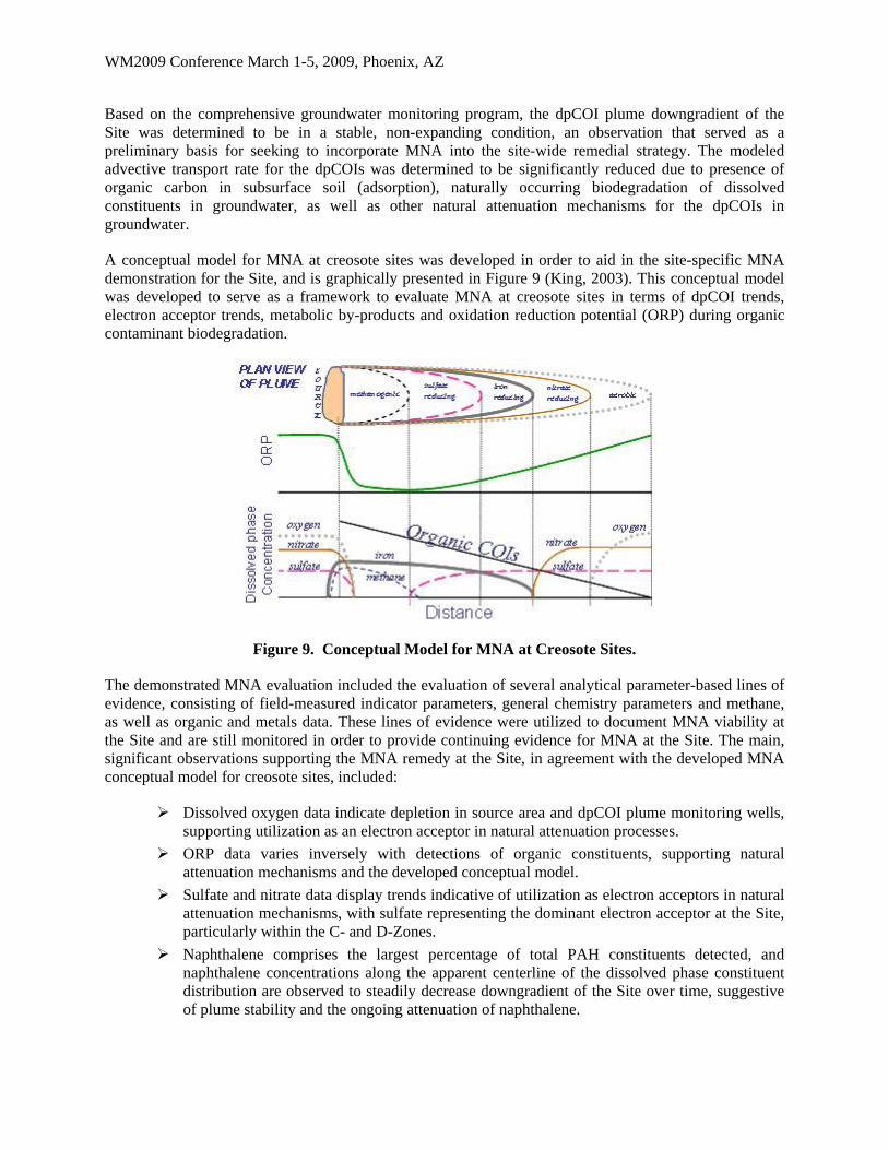
A conceptual model for MNA at creosote sites was developed in order to aid in the site-specific MNA demonstration for the Site, and is graphically presented in Figure 9 (King, 2003). This conceptual model was developed to serve as a framework to evaluate MNA at creosote sites in terms of dpCOI trends, electron acceptor trends, metabolic by-products and oxidation reduction potential (ORP) during organic contaminant biodegradation.
Figure 9. Conceptual Model for MNA at Creosote Sites.
The demonstrated MNA evaluation included the evaluation of several analytical parameter-based lines of evidence, consisting of field-measured indicator parameters, general chemistry parameters and methane, as well as organic and metals data. These lines of evidence were utilized to document MNA viability at the Site and are still monitored in order to provide continuing evidence for MNA at the Site. The main, significant observations supporting the MNA remedy at the Site, in agreement with the developed MNA conceptual model for creosote sites, included:
Dissolved oxygen data indicate depletion in source area and dpCOI plume monitoring wells, supporting utilization as an electron acceptor in natural attenuation processes.
ORP data varies inversely with detections of organic constituents, supporting natural attenuation mechanisms and the developed conceptual model.
Sulfate and nitrate data display trends indicative of utilization as electron acceptors in natural attenuation mechanisms, with sulfate representing the dominant electron acceptor at the Site, particularly within the C- and D-Zones.
Naphthalene comprises the largest percentage of total PAH constituents detected, and naphthalene concentrations along the apparent centerline of the dissolved phase constituent distribution are observed to steadily decrease downgradient of the Site over time, suggestive of plume stability and the ongoing attenuation of naphthalene.
WM2009 Conference March 1-5, 2009, Phoenix, AZ
The highest concentrations of methane are coincident with the delineated dpCOI plume, therefore, methanogenesis also appears to be a substantial contributor to the ongoing natural attenuation processes.
These data provide for multiple lines of evidence to support the occurrence of natural attenuation processes within groundwater at the Site. The analysis of the MNA parameters over time through the groundwater monitoring program proved highly beneficial in documenting and supporting the occurrence of biodegradation and attenuation of the dpCOIs within groundwater beneath and downgradient of the Site. In order to further support the viability of the application of MNA at the Site, a mass discharge flux evaluation was undertaken.
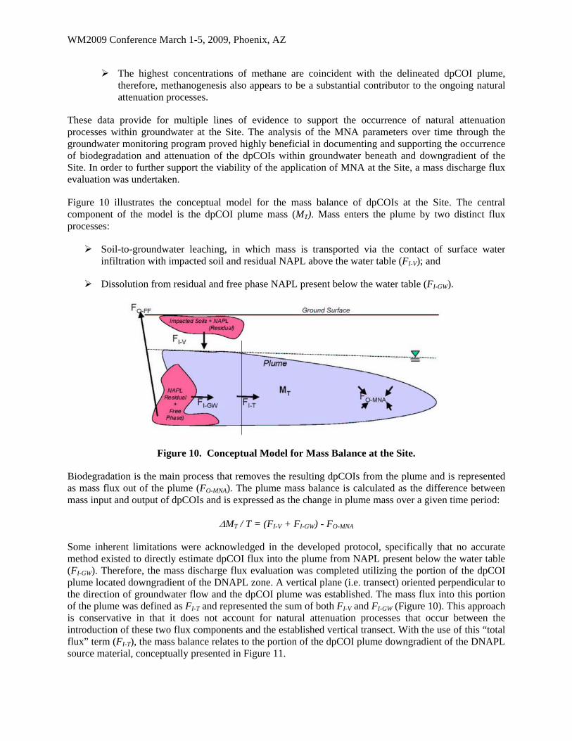
Figure 10 illustrates the conceptual model for the mass balance of dpCOIs at the Site. The central component of the model is the dpCOI plume mass (MT). Mass enters the plume by two distinct flux processes:
Soil-to-groundwater leaching, in which mass is transported via the contact of surface water infiltration with impacted soil and residual NAPL above the water table (FI-V); and
Dissolution from residual and free phase NAPL present below the water table (FI-GW).
Figure 10. Conceptual Model for Mass Balance at the Site.
Biodegradation is the main process that removes the resulting dpCOIs from the plume and is represented as mass flux out of the plume (FO-MNA). The plume mass balance is calculated as the difference between mass input and output of dpCOIs and is expressed as the change in plume mass over a given time period:
MT / T = (FI-V + FI-GW) - FO-MNA
Some inherent limitations were acknowledged in the developed protocol, specifically that no accurate method existed to directly estimate dpCOI flux into the plume from NAPL present below the water table (FI-GW). Therefore, the mass discharge flux evaluation was completed utilizing the portion of the dpCOI plume located downgradient of the DNAPL zone. A vertical plane (i.e. transect) oriented perpendicular to the direction of groundwater flow and the dpCOI plume was established. The mass flux into this portion of the plume was defined as FI-T and represented the sum of both FI-V and FI-GW (Figure 10). This approach is conservative in that it does not account for natural attenuation processes that occur between the introduction of these two flux components and the established vertical transect. With the use of this “total flux” term (FI-T), the mass balance relates to the portion of the dpCOI plume downgradient of the DNAPL source material, conceptually presented in Figure 11.

WM2009 Conference March 1-5, 2009, Phoenix, AZ
Figure 11. Conceptual Model for MNA at Creosote Sites.
The comprehensive groundwater monitoring database was utilized to complete the mass discharge flux evaluation for representative dpCOIs. The naphthalene discharge flux evaluation results are presented herein as it represents the most prevalently detected compound at the Site.
Figure 12 presents iso-concentration contours for dpCOI naphthalene in the D-Zone. These figures present quarterly averaged data, presented averaged on an annual basis.
Figure 12: Iso-concentration Contours for Stable Naphthalene Plume in D-Zone (ppb).
The respective iso-concentration contours were used to calculate naphthalene mass (MT) using the measured volumes between contour lines and the average concentration of the two bounding contour lines. The downgradient naphthalene plume mass (MDG-T) was calculated in the same fashion for that portion of the plume located downgradient of the established transect.
The component of upgradient naphthalene plume mass (MUG-T) was assigned as the difference between MT and MDG-T and utilized to estimate the mass flux across the transect (FI-T) over time. The mass flux (FI-
T) was calculated by determining the area of the respective dpCOI at the transect (AT), the average

WM2009 Conference March 1-5, 2009, Phoenix, AZ
concentration of the transect (CT), and the average groundwater flux rate (FG) at the transect, according to the following equation:
FI-T = AT x CT x FG
The findings indicated that the overall plume mass (MT) indicated plume stability with evident mass reduction, consistent with the prior MNA demonstration. Further, Figure 13 presents the summarized downgradient naphthalene plume mass (MDG-T) and Figure # present the naphthalene mass flux (FI-T). The variability in naphthalene mass flux (FI-T), portrayed in Figure 14, is attributed to the operating DNAPL recovery wells, located immediately upgradient of the established transect. These figures verify that the dpCOI plume is stable and that the natural attenuation capacity of the aquifer (FO-MNA) is greater than the observed mass flux (FI-T).
0
2,000
4,000
6,000
8,000
10,000
12,000
14,000
16,000
Do
wn
gra
die
nt
Plu
me
Ma
ss
2001 2002 2003 2004 0
50
100
150
200
250
Mas
s L
oa
din
g
2001 2002 2003 2004
Figure 13. Naphthalene Plume Mass Figure 14. Naphthalene Mass Flux Downgradient of Transect (MDG-T) [grams]. Loading at Transect (FI-T) [grams per day].
Through 2007, the DNAPL recovery efforts undertaken at the Site since 1998 have recovered over 121,552 gallons of creosote, which translates to approximately 1.12 MM pounds or 5.1 x 10⁸ grams (FO-
FF). While the mass of creosote DNAPL recovered (FO-FF) is not strictly a component of the dpCOI mass discharge flux evaluation, it is presented to demonstrate that the enhanced DNAPL recovery efforts account for the most significant mass removal as compared to all other mass removal processes occurring at the Site.
The mass discharge flux evaluation served to verify and support the MNA remedy for groundwater downgradient of the Site and the ongoing DNAPL recovery efforts satisfy regulatory requirements and directives to complete source removal, to the extent practical. However, ultimate groundwater restoration to maximum contaminant levels (MCLs), as noted in numerous regulatory guidance (EPA, 1993b; 2000; 2003), is not likely for a majority of DNAPL sites. Therefore, the achievable corrective action objective for groundwater is to prevent dpCOI migration and prevent exposure in order to ensure protectiveness to human health and the environment, to the extent practicable.
Institutional Controls
The site-specific risk assessment indicated that no current potential unacceptable risk exists for dpCOI in groundwater due to incomplete exposure pathways. However, in order to meet regulatory requirements, afforded mechanisms in the CAS Program were implemented to ensure that the groundwater pathway would remain incomplete. Specifically, a CAS Program-afforded risk management tool (i.e. institutional controls [ICs]) was enacted for the area downgradient of the Site to ensure ongoing protection of human health and the environment. The ICs prohibit groundwater consumption in the area of delineated dissolved phase constituents in conjunction with monitoring potential future groundwater usage in an associated area.
WM2009 Conference March 1-5, 2009, Phoenix, AZ
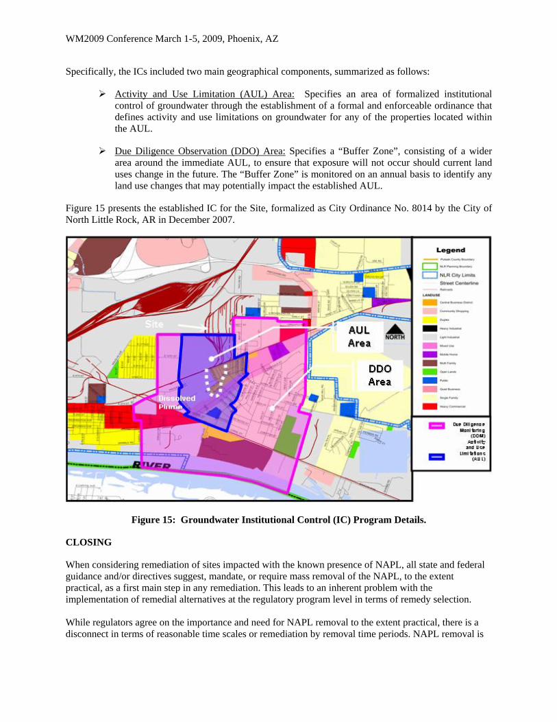
Specifically, the ICs included two main geographical components, summarized as follows:
Activity and Use Limitation (AUL) Area: Specifies an area of formalized institutional control of groundwater through the establishment of a formal and enforceable ordinance that defines activity and use limitations on groundwater for any of the properties located within the AUL.
Due Diligence Observation (DDO) Area: Specifies a “Buffer Zone”, consisting of a wider area around the immediate AUL, to ensure that exposure will not occur should current land uses change in the future. The “Buffer Zone” is monitored on an annual basis to identify any land use changes that may potentially impact the established AUL.
Figure 15 presents the established IC for the Site, formalized as City Ordinance No. 8014 by the City of North Little Rock, AR in December 2007.
Figure 15: Groundwater Institutional Control (IC) Program Details.
CLOSING
When considering remediation of sites impacted with the known presence of NAPL, all state and federal guidance and/or directives suggest, mandate, or require mass removal of the NAPL, to the extent practical, as a first main step in any remediation. This leads to an inherent problem with the implementation of remedial alternatives at the regulatory program level in terms of remedy selection. While regulators agree on the importance and need for NAPL removal to the extent practical, there is a disconnect in terms of reasonable time scales or remediation by removal time periods. NAPL removal is
WM2009 Conference March 1-5, 2009, Phoenix, AZ
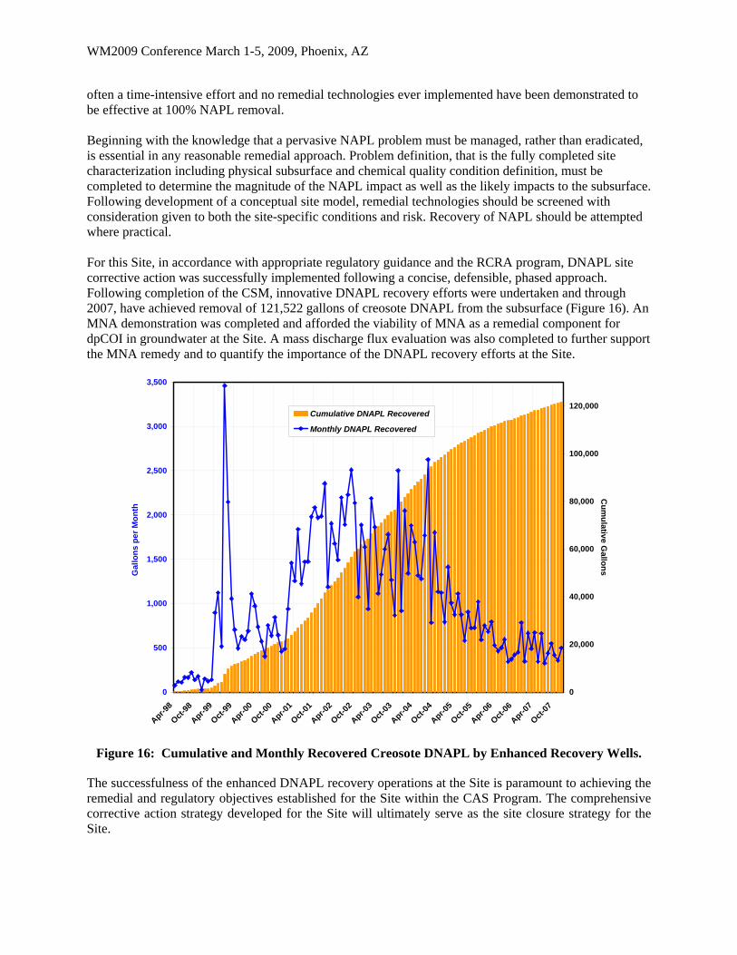
often a time-intensive effort and no remedial technologies ever implemented have been demonstrated to be effective at 100% NAPL removal. Beginning with the knowledge that a pervasive NAPL problem must be managed, rather than eradicated, is essential in any reasonable remedial approach. Problem definition, that is the fully completed site characterization including physical subsurface and chemical quality condition definition, must be completed to determine the magnitude of the NAPL impact as well as the likely impacts to the subsurface. Following development of a conceptual site model, remedial technologies should be screened with consideration given to both the site-specific conditions and risk. Recovery of NAPL should be attempted where practical. For this Site, in accordance with appropriate regulatory guidance and the RCRA program, DNAPL site corrective action was successfully implemented following a concise, defensible, phased approach. Following completion of the CSM, innovative DNAPL recovery efforts were undertaken and through 2007, have achieved removal of 121,522 gallons of creosote DNAPL from the subsurface (Figure 16). An MNA demonstration was completed and afforded the viability of MNA as a remedial component for dpCOI in groundwater at the Site. A mass discharge flux evaluation was also completed to further support the MNA remedy and to quantify the importance of the DNAPL recovery efforts at the Site.
0
500
1,000
1,500
2,000
2,500
3,000
3,500
Apr-98
Oct-9
8
Apr-99
Oct-9
9
Apr-00
Oct-0
0
Apr-01
Oct-0
1
Apr-02
Oct-0
2
Apr-03
Oct-0
3
Apr-04
Oct-0
4
Apr-05
Oct-0
5
Apr-06
Oct-0
6
Apr-07
Oct-0
7
Gal
lon
s p
er
Mo
nth
0
20,000
40,000
60,000
80,000
100,000
120,000
Cu
mu
lativ
e Ga
llon
s
Cumulative DNAPL Recovered
Monthly DNAPL Recovered
Figure 16: Cumulative and Monthly Recovered Creosote DNAPL by Enhanced Recovery Wells.
The successfulness of the enhanced DNAPL recovery operations at the Site is paramount to achieving the remedial and regulatory objectives established for the Site within the CAS Program. The comprehensive corrective action strategy developed for the Site will ultimately serve as the site closure strategy for the Site.
WM2009 Conference March 1-5, 2009, Phoenix, AZ
REFERENCES
Environment Agency, 2003, An Illustrated Handbook of DNAPL Transport and Fate in the Subsurface, Bristol, UK.
Gordon, M., J. Tracey, and M. Ellis, 1958. Geology of the Arkansas Bauxite Region. United States Geological Survey Professional Paper 299.
ITRC, 2004, Strategies for Monitoring the Performance of DNAPL Source Zone Remedies, Interstate Technology and Regulatory Council, Dense Non-aqueous Phase Liquids Team, ITRC/DNAPLs-5.
King, M.W.G., Barker, J., 1999. Migration and natural fate of a coal tar creosote plume: 1. Overview and plume development. Journal of Contaminant Hydrology, 39:281-307.
King, Mark. 2003. Natural Attenuation of PAHs in Groundwater. Web-based course conducted for the Environmental Institute for Continuing Education.
U.S. EPA, 1992, Considerations in Ground-Water Remediation at Superfund Sites and RCRA Facilities – Update, OSWER Directive 9283.1-06, Office of Solid Waste and Emergency Response, Washington, D.C.
U.S. EPA, 1993a, Presumptive Remedies: Technology Selection Guide for Wood Treater Sites, EPA/540-F-93-020, Office of Solid Waste and Emergency Response, Washington, D.C.
U.S. EPA, 1993b, Guidance for Evaluating the Technical Impracticability of Ground-Water Restoration, EPA/540-R-93-080, OSWER Directive 9234.2-25, Office of Solid Waste and Emergency Response, Washington, D.C.
U.S. EPA, 1995, Consistent Implementation of the FY 1993 Guidance on Technical Impracticability of Ground-Water Restoration at Superfund Sites, OSWER Directive 9200.4-14, Office of Solid Waste and Emergency Response, Washington, D.C.
U.S. EPA, 1997, Rules of Thumb for Superfund Remedy Selection, EPA/540/R/97/013, Office of Solid Waste and Emergency Response, Washington, D.C.
U.S. EPA, 2000, Region 6 Corrective Action Strategy – Guide for Pilot Projects, prepared by USEPA Region 6, Dallas, Texas, November 2000.
U.S. EPA, 2003, The DNAPL Remediation Challenge: Is there a Case for Partial Source Depletion?, EPA/600-R-03-143, Office of Research and Development, Cincinnati, OH.
U.S. EPA, 2004, Performance Monitoring of MNA Remedies for VOCs in Ground Water, EPA/600/R-04/027, Office of Research and Development, Cincinnati, OH.