sissor table
DESCRIPTION
Sissor TableTRANSCRIPT

�����������
�
�� �����
������������������� ���������� �� ��!
��������� � � � ��������� �������������
���������� ������� ��������� !"�#
�������������$�
�
������������
�
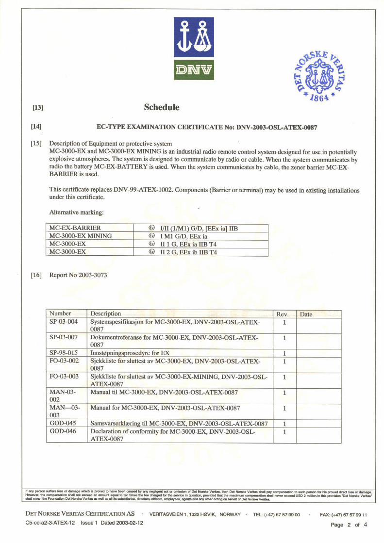
�
�������� ��%����
�&&��
���'����(��()���
�
�
�
*�����
�
�
�
�&�&�&���+��,�-����./$��
��,�-����./�!���
��0*.&&&
�1��
2��3����(��
�
� �
��
�4�5��& �4�5���
�4�54��
��,�-����!/$�
���,�-����!/�!���
�
�
0*6&&&
�1��
*��-��%�� �� � �6�� � � �6�� ����)�,����./� �����.��
��(���� 2�+ & ����)�,����!/� �����6��
�����������
��,���������
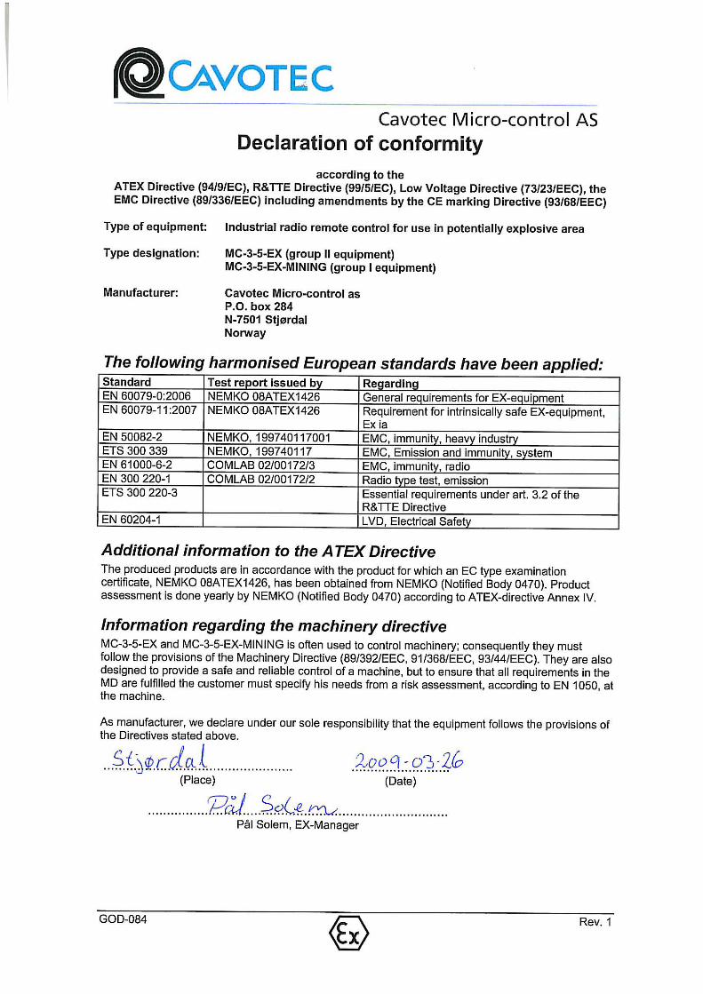
���������������� ������������ ������ ������������ ���������
��������� ���� ������� ���� ����� ����������!"#$�%&'!(#��)*&�����

�����������
�
�� �����
������������������� ���������� �� ��!
��������� � � � ��������� �������������
���������� ������� ��������� !"�#
�������������$�
�
������������
�
�
�������� ��%����
�&&��
���'����(��()���
�
�
�
*�����
�
�
�
�&�&�&���+��,�-����./$��
��,�-����./�!���
��0*.&&&
�1��
2��3����(��
�
� �
��
�4�54�& �4�5���
�4�5���
��,�-����!/$�
���,�-����!/�!���
�
�
0*6&&&
�1��
*��-��%�� �� � �6�� � � �6�� ����)�,����./� ����7.��
��(���� 2�+ & ����)�,����!/� ����76��
�����������
��,���������
���������������� ������������ ������ ������������ ���������
��������� ���� ������� ���� ����� ����������!"#$�%&'!(#��)*&����+


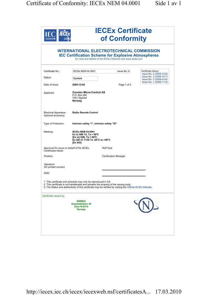
IECEx Certificateof Conformity
INTERNATIONAL ELECTROTECHNICAL COMMISSION IEC Certification Scheme for Explosive Atmospheres
for rules and details of the IECEx Scheme visit www.iecex.com
Certificate No.: IECEx NEM 04.0001 issue No.:4
Status: Current
Date of Issue: 2009-12-08 Page 1 of 5
Applicant:
Electrical Apparatus: Radio Remote ControlOptional accessory:
Type of Protection: Intrinsic safety "i", intrinsic safety "iD"
Marking: IECEx NEM 04.0001Ex ia I/IIB T4, Ta = 50ºC [Ex ia] I/IIB, Ta = 60ºC Ex ibD 21 T130 Ta -20°C to +50°C [Ex ibD]
Approved for issue on behalf of the IECEx Certification Body:
Rolf Hoel
Position: Certification Manager
Signature:(for printed version)
Date:
1. This certificate and schedule may only be reproduced in full. 2. This certificate is not transferable and remains the property of the issuing body. 3. The Status and authenticity of this certificate may be verified by visiting the Official IECEx Website.
Certificate issued by:
NEMKO Gaustadelleen 30
Oslo N-0314 Norway
Certificate history:
Issue No. 4 (2009-12-8)Issue No. 3 (2009-10-7)Issue No. 2 (2008-9-24)Issue No. 1 (2006-11-8)
Cavotec Micro-Control ASP.O. Box 284 7501 Stjørdal
Norway
Side 1 av 1Certificate of Conformity: IECEx NEM 04.0001
17.03.2010http://iecex.iec.ch/iecex/iecexweb.nsf/certificatesA...
IECEx Certificateof Conformity
Certificate No.: IECEx NEM 04.0001
Date of Issue: 2009-12-08 Issue No.: 4
Page 2 of 5
Manufacturer:
Manufacturing location(s):
This certificate is issued as verification that a sample(s), representative of production, was assessed and tested and found to comply with the IEC Standard list below and that the manufacturer's quality system, relating to the Ex products covered by this certificate, was assessed and found to comply with the IECEx Quality system requirements. This certificate is granted subject to the conditions as set out in IECEx Scheme Rules, IECEx 02 and Operational Documents as amended.
STANDARDS:The electrical apparatus and any acceptable variations to it specified in the schedule of this certificate and the identified documents, was found to comply with the following standards:
IEC 60079-0 : 2000Edition: 3.1
Electrical apparatus for explosive gas atmospheres - Part 0: General requirements
IEC 60079-11 : 1999Edition: 4
Electrical apparatus for explosive gas atmospheres - Part 11: Intrinsic safety 'i'
IEC 61241-0 : 2004Edition: 1
Electrical apparatus for use in the presence of combustible dust - Part 0: General requirements
IEC 61241-11 : 2005Edition: 1
Electrical apparatus for use in the pressence of combustible dusts - Part 11: Protection by intrinsic safety 'iD'
This Certificate does not indicate compliance with electrical safety and performance requirements other than those expressly included in the Standards listed above.
TEST & ASSESSMENT REPORTS:A sample(s) of the equipment listed has successfully met the examination and test requirements as recorded in
IECEx ATR: File Reference:
NO/NEM/04/19655 19655NO/NEM/04/19655.02 106811NO/NEM/ExTR09.0010/00 129470
Cavotec Micro-Control ASWessels vei 2 7501 Stjørdal
Norway
Side 1 av 1Certificate of Conformity: IECEx NEM 04.0001
17.03.2010http://iecex.iec.ch/iecex/iecexweb.nsf/certificatesA...

IECEx Certificateof Conformity
Certificate No.: IECEx NEM 04.0001
Date of Issue: 2009-12-08 Issue No.: 4
Page 3 of 5
Schedule
EQUIPMENT:Equipment and systems covered by this certificate are as follows:
The Radio Remote Control comprises a portable terminal unit for use in the hazardous location. Carrier belt is fixed to the terminal and then fastened to the operator's waist. The system is designed to communicate by radio or cable. When the system communicates by radio, a battery is placed in the terminal unit and supplies it with power. When the system communicates by cable, a zener barrier is used. Charging of battery must take place in non-classified location. The Base unit is connected to a machine/PLS. For use in non-classified locataion. The base unit has an intrinsically safe output circuit for connection of an antenna cable of 5-10 m length. An antenna placed directly at the base unit or connected via an antenna cable is not part of the certified apparatus but may be used under the concept of IEC 60079-11 clause 5.4 "Simple Apparatus". The device has additionally been evaluated for an ingress protection rating of IP65.
CONDITIONS OF CERTIFICATION: NO
Side 1 av 1Certificate of Conformity: IECEx NEM 04.0001
17.03.2010http://iecex.iec.ch/iecex/iecexweb.nsf/certificatesA...
IECEx Certificateof Conformity
Certificate No.: IECEx NEM 04.0001
Date of Issue: 2009-12-08 Issue No.: 4
Page 4 of 5
EQUIPMENT(continued):
Model/Type designation MC-3000-EX & MC-3000-EX-MINING: Ex ia I/IIB T4, Ta: 50°C. MC-EX-BATTERY2: Ex ia I/IIB T4 Ta: -20°C to +50°C MC-EX-BARRIER: [Ex ia] I/IIB, Ta: 60°C. MC-3-5 EX: Ex ia IIB T4 Ta: -20°C to +50°C MC-3-5 EX MINING: Ex ia I Ta: -20°C to +50°C MC-3-6 EX: Ex ia IIB T4 Ta: -20°C to +50°C MC-3-6 EX MINING: Ex ia I Ta: -20°C to +50°C MC-EX-BATTERY3: Ex ia I/IIB T4 Ta: -20°C to +50°C
Dust approval: MC-3-5 EX with MC-EX-BATTERY3 and MC-EX-BARRIER: Ex ibD 21 T130 Ta -20°C to +50°C / [Ex ibD]
Side 1 av 1Certificate of Conformity: IECEx NEM 04.0001
17.03.2010http://iecex.iec.ch/iecex/iecexweb.nsf/certificatesA...
IECEx Certificateof Conformity
Certificate No.: IECEx NEM 04.0001
Date of Issue: 2009-12-08 Issue No.: 4
Page 5 of 5
DETAILS OF CERTIFICATE CHANGES (for issues 1 and above):
Issue 1: To include an alternative design of the battery pack used for the MC-3000-EX. The battery pack is named MC-EX-BATTERY2. It also covers an alternative shape of the enclosure. In this alternative version the product is named MC-3-6 EX and the battery pack MC-EX-BATTERY3. Issue 2: This issue covers an alternative shape of the enclosure. In this alternative version the product is named MC-3-5 EX. It also cover two new electronic modules inside the equipment, MC-TX-KB4 and MC-EX-CD-PLL. The MC-TX-KB4 module is an alternative to the old MC-TX-KB2 module. The MC-EX-PLL radio module is an alternative to the old MC-EX-PLL440C radio module. Issue 3: The MC-3-5 EX radio remote control, with MC-EX-BATTERY3 and MC-EX-BARRIER have been approved according to IEC61241-0:2004 and IEC61241-11:2004 for use in precense of combustible dust. Protection by intrinsic safety "iD". Issue 4: The certificate is updatet with a new issue due to missing information in issue 3. No technical changes or changes to the documentation.
Side 1 av 1Certificate of Conformity: IECEx NEM 04.0001
17.03.2010http://iecex.iec.ch/iecex/iecexweb.nsf/certificatesA...


SP-07-006 Rev. 5 This is a Schedule document, do NOT change without approval from the certification body.
Module specification for MC-CD-PLL

Page 2 of 4
SP-07-006 Rev. 5 This is a Schedule document, do NOT change without approval from the certification body.
Introduction MC-CD-PLL/MC-EX-CD-PLL is a multi-channel radio receiver and transmitter suited for simplex and duplex radio remote control systems from Cavotec Micro-control as. The EX version, MC-EX-CD-PLL, is approved for use in explosive areas.
AbbreviationsLED Light emitting diode
PLL Phase Locked Loop
Versions and order numbers MC order no. Part name Frequency
[MHz]
Data rate
[bps]
Channel
Separation
[kHz]
Output
Power
[mW]
M5-1012-7038 MC-CD-PLL 434 433.050-434.775 9600 25 10
M9-1012-7038 MC-EX-CD-PLL 434 433.050-434.775 9600 25 10
M5-1012-7031 MC-CD-PLL 458 458.525-459.175 9600 25 10
M9-1012-7031 MC-EX-CD-PLL 458 458.525-459.175 9600 25 10
M5-1012-7035 MC-CD-PLL 419 418.725-419.400 9600 25 10
M9-1012-7035 MC-EX-CD-PLL 419 418.725-419.400 9600 25 10
M5-1012-7037 MC-CD-PLL 429 429.250-429.7375 4800 12.5 10
M5-1012-7030 MC-CD-PLL 447 447.275-447.9875 4800 12.5 10
M5-1012-7033 MC-CD-PLL-335 335.7125-335.8375 4800 12.5 1
M5-1012-7139 MC-CD-PLL-440 438.000-442.000 4800 12.5 10
M5-1012-7046 MC-CD-PLL-460 458.000-462.500 4800 12.5 10
M5-1012-7086 MC-CD-PLL-869 868.000-870.000 9600 25 5
Comp Name See chapt.
J1 Programming port Connections
J2 TX-bus Connections
J3 Antenna Connections
D1 RX-LED (Green) Indicators
D2 DCD-LED (Green) Indicators
D3 TX-LED (Red) Indicators
Page 3 of 4
SP-07-006 Rev. 5 This is a Schedule document, do NOT change without approval from the certification body.
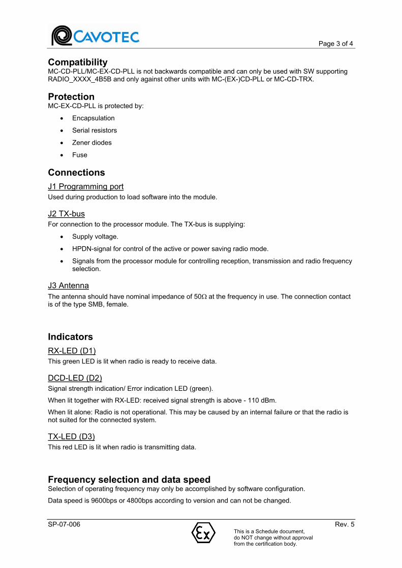
Compatibility MC-CD-PLL/MC-EX-CD-PLL is not backwards compatible and can only be used with SW supporting RADIO_XXXX_4B5B and only against other units with MC-(EX-)CD-PLL or MC-CD-TRX.
ProtectionMC-EX-CD-PLL is protected by:
Encapsulation
Serial resistors
Zener diodes
Fuse
Connections
J1 Programming port
Used during production to load software into the module.
J2 TX-bus
For connection to the processor module. The TX-bus is supplying:
Supply voltage.
HPDN-signal for control of the active or power saving radio mode.
Signals from the processor module for controlling reception, transmission and radio frequency selection.
J3 Antenna
The antenna should have nominal impedance of 50! at the frequency in use. The connection contact is of the type SMB, female.
Indicators
RX-LED (D1)
This green LED is lit when radio is ready to receive data.
DCD-LED (D2)
Signal strength indication/ Error indication LED (green).
When lit together with RX-LED: received signal strength is above - 110 dBm.
When lit alone: Radio is not operational. This may be caused by an internal failure or that the radio is not suited for the connected system.
TX-LED (D3)
This red LED is lit when radio is transmitting data.
Frequency selection and data speed Selection of operating frequency may only be accomplished by software configuration.
Data speed is 9600bps or 4800bps according to version and can not be changed.

Page 4 of 4
SP-07-006 Rev. 5 This is a Schedule document, do NOT change without approval from the certification body.
Specifications Supply voltage:
Via cable from the processor module (TX-bus): 6.0V – 15.0V (Nominal 7.2V)
Current consumption:
In RX mode: < 50 mA
In TX mode: < 65 mA
In HPDN mode: < 0.5 mA for NON-EX-versions
< 1mA for EX-versions
Radio specification:
Conforms to: EN 300 220-2
Approval: FCC Part 90
Output power: 1 - 10 mW
Data speed: 9600 bps or 4800bps
Sensitivity: better than -110 dBm
Modulation: FM-modulation
+/- 2.75kHz @ 9600bps
+/- 2.0kHz @ 4800bps

Micro-control as Module specification for MC-IRX Analog Page 1 of 6
SP-03-002 Rev. 5
Module specification for MC-IRX Analog
Document number
SP-03-002

Micro-control as Module specification for MC-IRX Analog Page 2 of 6
SP-03-002 Rev. 5
ModuleThis module specification refers to MC-IRX-analog. The module looks like this (No add-on modules mounted):
Grey donuts is mounting holes. Grey figures around mounting holes are supports from the standard plastic enclosure.
Components Name See chapter J1 MUS-bus Connections
J4, J6 and J7 Terminal strip Connections
D5 and D6 Status indicators Indicators
JP1 Board address Configuration
JP3-JP5 Plug in for add-on boards Current outputs
Terms ANA-M Short for MC-IRX-ANA-M 6 channel voltage output board. (MC-IRX Analog module mainboard) ANA-PWM Short for the 2 channel PWM current output board (0-3A) LED Light emitting diode Link Electric connection placed between two PCB connection points to configure the module function.
Functionality ANA-M is a 3x2-channel analog voltage output board with a resolution of 11 BIT. The output voltage range is maximum ± 10V, and may be configured for any value between this limits.
The voltage may also be adjusted to control Danfoss hydraulic valves, with neutral at 50% of the power supply voltage for the valve. The maximum voltage range is 25% to 75%. The output voltage varies in proportion to the supply voltage.
Micro-control as Module specification for MC-IRX Analog Page 3 of 6
SP-03-002 Rev. 5
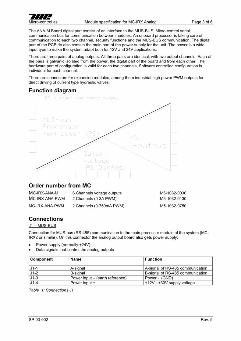
The ANA-M Board digital part consist of an interface to the MUS-BUS, Micro-control serial communication bus for communication between modules. An onboard processor is taking care of communication to each two channel, security functions and the MUS-BUS communication. The digital part of the PCB do also contain the main part of the power supply for the unit. The power is a wide input type to make the system adapt both for 12V and 24V applications.
There are three pairs of analog outputs. All three pairs are identical, with two output channels. Each of the pairs is galvanic isolated from the power, the digital part of the board and from each other. The hardware part of configuration is valid for each two channels. Software controlled configuration is individual for each channel.
There are connectors for expansion modules, among them industrial high power PWM outputs for direct driving of current type hydraulic valves.
Function diagram
Order number from MC MC-IRX-ANA-M 6 Channels voltage outputs M5-1032-0030
MC-IRX-ANA-PWM 2 Channels (0-3A PWM) M5-1032-0130
MC-IRX-ANA-PWM 2 Channels (0-750mA PWM) M5-1032-0750
ConnectionsJ1 – MUS-BUS
Connection for MUS-bus (RS-485) communication to the main processor module of the system (MC-IRX2 or similar). On this connector the analog output board also gets power supply:
Power supply (normally +24V).
Data signals that control the analog outputs
Component Name Function
J1-1 A-signal A-signal of RS-485 communication
J1-2 B-signal B-signal of RS-485 communication
J1-3 Power input – (earth reference) Power - (GND)
J1-4 Power input + +12V - +30V supply voltage
Table 1: Connections J1
Micro-control as Module specification for MC-IRX Analog Page 4 of 6
SP-03-002 Rev. 5
J4, J6 and J7 – terminal strip
J4, J6 and J7 are 6-pins plug-in screw terminals. If the module is changed, the entire screw terminal can be pulled out and plugged into the new module. See the table below for a summary of the functions for the screw terminals. The table is a listing for J4 channels CH1-CH2. J7 is for channels CH3-CH4. J6 is for channels CH5-CH6. The pin numbers are equal for each of the connectors (terminal strips).
Component Name Function J4-1 Power – (earth reference) Power -
J4-2 Power + Power +
J4-3 Output Ground Output Ground (same for both output channels)
J4-4 Vout 1 Analog channel 1 voltage output
J4-5 Output Ground Output Ground (same for both output channels)
J4-6 Vout 2 Analog channel 2 voltage output
Table 2: Connections J4
Indicators
LED Color Function D5 Green Illuminated (steady light) when the module has established contact with the
systems main processor/receiver module. (MC-IRX2)
D6 Red Illuminated (steady light) indicates faults
Table 3: Light emitting diode indicators at the front right hand side of the ANA-M PCB.
Configuring The ANA-M-module may be hardware configured by:
There may be 2 main analog boards on each system, each with six channels. JP1 sets the board address. With jumper not fitted the first six channels is enabled. Channel 0_1/ 0_2, 1_1/1_2 and 2_1/2_2. (There is no galvanic isolation between each two channels like 0_1/0_2 but galvanic isolation is established between the different pairs like 0_x and 1_x). With JP1 fitted the following channels is enabled on the board: Channel 3_1/3_2, 4_1/4_2 and 5_1/5_2. Please se mapping table below.
Cutting links LK1-LK3 for enabling offset adjustments. This offset adjustment (or position) is considered as the safe condition for the device operated from the module output. LK1 for CH1/ CH2 (named 0_1/ 0_2 in the setup file), LK2 for CH3/CH4 and LK3 for CH5/CH6.
ChannelNaming on PCB
JP1 Not fittedChannel no. in
system
JP1 Fitted Channel no. in
systemOffset Link
OffsetPotentiometer
1 0_1 3_1
2 0_2 3_2 LK1 R115
3 1_1 4_1
4 1_2 4_2 LK2 R71
5 2_1 5_1
6 2_2 5_2 LK3 R159
Micro-control as Module specification for MC-IRX Analog Page 5 of 6
SP-03-002 Rev. 5
Adjusting offset of the channels is done by potentiometers R115, R71 and R159. There is not individual channel adjustment, but adjustment for every two channels. R115 is for CH1/CH2, R71 for CH3/CH4 and R159 for CH5/CH6.
The range 25%-75% for Danfoss valves is automatically adjusted to adapt for both 12V and 24V Danfoss valves.
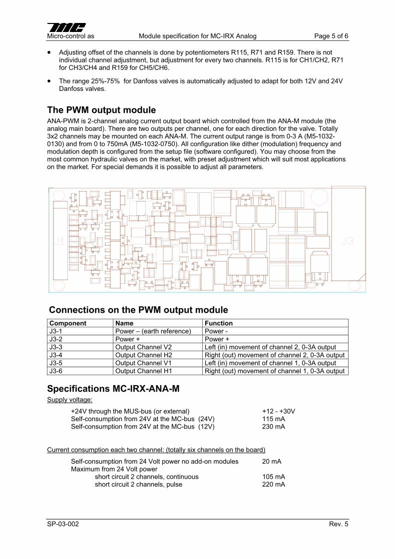
The PWM output module ANA-PWM is 2-channel analog current output board which controlled from the ANA-M module (the analog main board). There are two outputs per channel, one for each direction for the valve. Totally 3x2 channels may be mounted on each ANA-M. The current output range is from 0-3 A (M5-1032-0130) and from 0 to 750mA (M5-1032-0750). All configuration like dither (modulation) frequency and modulation depth is configured from the setup file (software configured). You may choose from the most common hydraulic valves on the market, with preset adjustment which will suit most applications on the market. For special demands it is possible to adjust all parameters.
Connections on the PWM output moduleComponent Name Function J3-1 Power – (earth reference) Power -
J3-2 Power + Power +
J3-3 Output Channel V2 Left (in) movement of channel 2, 0-3A output
J3-4 Output Channel H2 Right (out) movement of channel 2, 0-3A output
J3-5 Output Channel V1 Left (in) movement of channel 1, 0-3A output
J3-6 Output Channel H1 Right (out) movement of channel 1, 0-3A output
Specifications MC-IRX-ANA-M Supply voltage:
+24V through the MUS-bus (or external) +12 - +30V Self-consumption from 24V at the MC-bus (24V) 115 mA Self-consumption from 24V at the MC-bus (12V) 230 mA
Current consumption each two channel: (totally six channels on the board)
Self-consumption from 24 Volt power no add-on modules 20 mA Maximum from 24 Volt power short circuit 2 channels, continuous 105 mA short circuit 2 channels, pulse 220 mA

Micro-control as Module specification for MC-IRX Analog Page 6 of 6
SP-03-002 Rev. 5
Analog output:
Channel x_1 !10V, 0-10V, !5V, 0-5V Offset adjustment, safe state by potentiometer. Span is adjusted by software.
Channel x_2 !10V, 0-10V, !5V, 0-5V offset adjustment, safe state by potentiometer. Span is adjusted by software.
Maximum output current each channel 5 mA
Specifications MC-IRX-ANA-PWM (2 channels) Analog output PWM:
Channel 1 (M5-1032-0130) 0-3 A (adjusted by software)
Channel 1 (M5-1032-0750) 0-750mA (adjusted by software)
Channel 2 (M5-1032-0130) 0-3 A (adjusted by software)
Channel 2 (M5-1032-0750) 0-750mA (adjusted by software)
PWM-frequency > 5KHz
Dither/Modulation frequency 5-400 Hz (adjusted by software)
Modulation depth 0-100% (adjusted by software)
Current consumption:
Self-consumption from MC-IRX-ANA-M 20mA
Normal consumption from external power 1.7 A (At 750 mA each channel)
Maximum from external power short circuit both channels, continuous <10 A short circuit both channels, pulse 20 A
SP-02-004 Rev. 7
Module specification, MC-IRX2
Document number
SP-02-004
This page is not a part of the customer manualand shall not be distributed!
Revision 1 2 3 4 5
Date 02.08.21 02.09.19 2003.04.11 2003.05.15 2004-11-17
Prepared by TOB JMi TOB TOB TOB
Checked by PB TOB JanL JanL
Approved by TOB TOB TOB TOB
Revision 6 7
Date 2009-05-27 2009-08-24
Prepared by MO MO
Checked by ToreS ToreS
Approved by PAS PAS
Path G:\02\SP\SP-02-004 Module specification, MC-IRX2.pdf
Module specification, MC-IRX2 Page 2 of 2
SP-02-004 Rev. 7
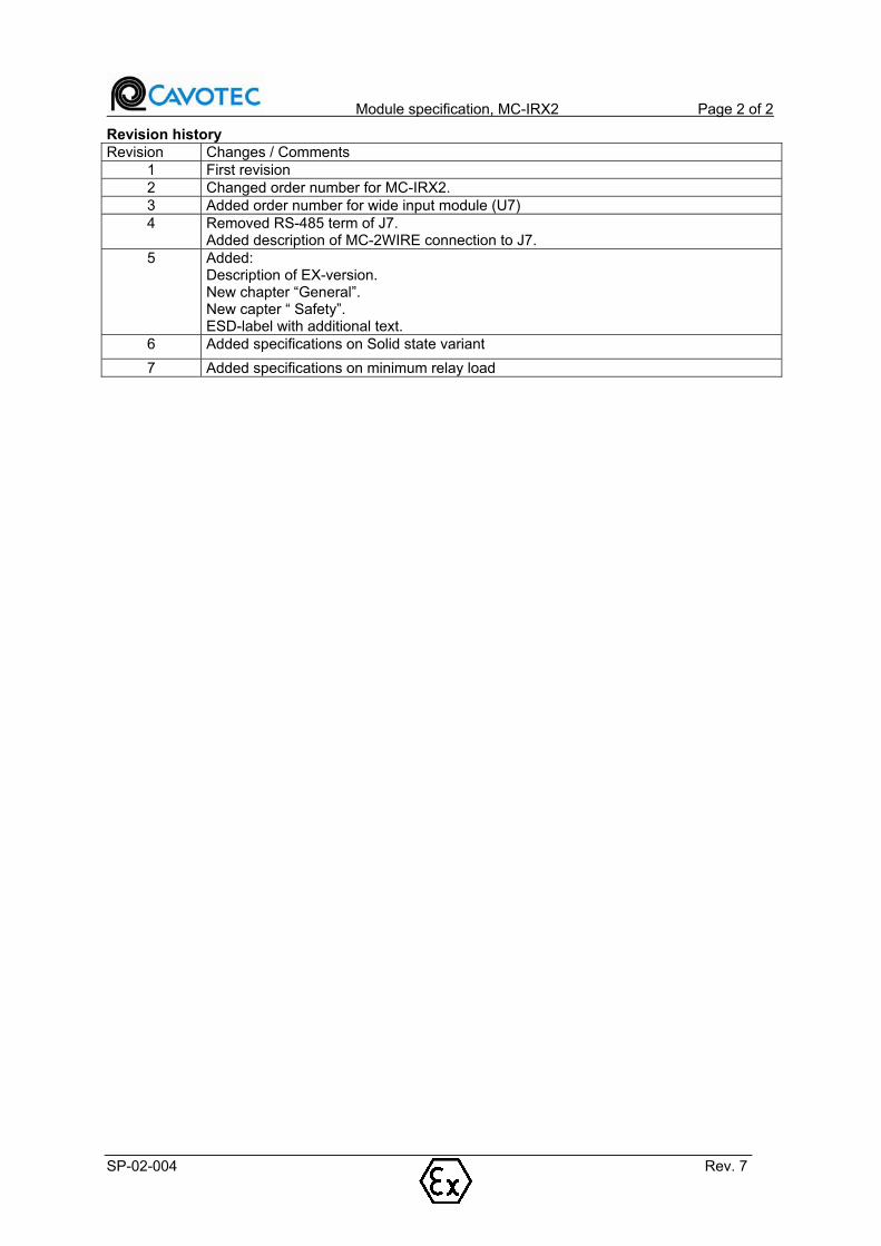
Revision history Revision Changes / Comments
1 First revision
2 Changed order number for MC-IRX2.
3 Added order number for wide input module (U7)
4 Removed RS-485 term of J7. Added description of MC-2WIRE connection to J7.
5 Added: Description of EX-version. New chapter “General”. New capter “ Safety”. ESD-label with additional text.
6 Added specifications on Solid state variant
7 Added specifications on minimum relay load
SP-02-004 Rev. 7
Module specification, MC-IRX2
Document number
SP-02-004

Module specification, MC-IRX2 Page 2 of 9
SP-02-004 Rev. 7
1. General MC-IRX2 exists in 4 variants:
Standard Input, Mechanical function relays
Wide Input, Mechanical function relays
Wide Input, Solid State function relays
Standard Input, EX version, approved for use in zone 2. Mechanical function relays.
Refer to Specifications (Chapter 11) for further description of each variant.
The circuit board is sensitive to electro static discharges. It is important to handle the circuit board in antistatic manners to prevent damage.
2. Safety MC-IRX2 is designed to fulfill the most stringent requirements regarding safety. A safety processor (SP) monitors duplicated safety relays, the main processor (MP) and the communication between base unit and terminal. The emergency stop functionality fulfils the requirements for category 4 in accordance with EN 954-1.
It is important to be aware of the limitations for the EX-version (M9-1070-0030), refer to chapter Specifications. Overriding these limitations may lead to dangerous situations.
3. Definitions MC-IRX2 Integrated receiver / processor module with I/O. Base station «Receiver»; the system part connected to the controlled object (the machine). Terminal «Transmitter» or «remote control»; the system part carried by the operator.Link Suspension bridge that may be cut to change the module’s function. Jumper A pair of pins that may be short-circuited using a separate short circuit hoop.
4. Module This module specification refers to MC-IRX2. The module looks like this:
*K1-K16 is encapsulated for EX-version (M9-1071-0030).

Module specification, MC-IRX2 Page 3 of 9
SP-02-004 Rev. 7
Component Name See chapter D20 Red LED Indicators
D21 Green LED Indicators
J1-J6 Digital outputs, 16 x 3A/5A (See specification) Connections
J7 MC cable communication Connections
J8 TX-bus Connections
J9 RX-bus Connections
J11 AUX bus for RS-485 communication Connections
J12 24 Volt supply voltage Connections
J13 4 x analog inputs, 4 x digital inputs (or 8 digital) Connections
J15 MUS-bus connection for external MC-modules Connections
J16 Connection for MC-2WIRE Connections
J17 Connection for Emergency Stop Relay Connections
JP2 Jumper for ISM-radio Configuration
JP3 MP-Boot-jumper/programming jumper for Main Processor
Configuration
JP4 Display connector Configuration
JP9 SP-Boot-jumper/ programming jumper for Safety Processor
Configuration
LK1 Link, must be cut when U7 is mounted (WIDE INPUT) Configuration
LK2-LK3 Link, must be cut when MC-2WIRE is mounted Configuration
P1 RS-232 communication port (for programming) Connections
SW1 Function selector/programming selector Configuration
SW2 Reset Configuration
SW3 Menu button A, Select Configuration
SW4 Menu button B, Enter Configuration
SW5 Menu function selector Configuration
U7 Wide input power (option) Options
U10 EEPROM Configuration
5. Functionality MC-IRX2 is only used in the base station. It is the «heart and brain» of the system. The module consists of:
- A processor with flash-memory to store data and configuration. The software and configuration of this processor to a great extent set the functionality of the base station.
- A safety processor (SP) monitoring the safety relay, main processor (MP) and communication
- Emergency stop functionality according to category 4 in EN954-1.
- 16 relay outputs, for variants with mechanical function relays 12 are closing and 4 are alternating. For the variant with solid state relays all outputs are only closing.
- 4 analog and 4 digital inputs (or 8 digital)
- Connection buses for old and new MC-modules.
- Connection to other modules in the MC-3000/MC-2000 family.
Module specification, MC-IRX2 Page 4 of 9
SP-02-004 Rev. 7
6. Indicators Name Colour Explanation
D20 Green Indicates normal operation.
D21 Red Indicates fault condition, all functions are in fail-safe condition.
2x16 character display with backlight. This is used to indicate status, configuration etc.
See also the software user manual for MC-IRX2.
7. Connections
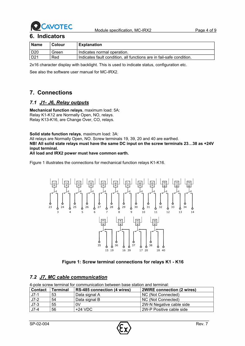
7.1 J1- J6, Relay outputs
Mechanical function relays, maximum load: 5A: Relay K1-K12 are Normally Open, NO, relays.Relay K13-K16, are Change Over, CO, relays.
Solid state function relays, maximum load: 3A: All relays are Normally Open, NO. Screw terminals 19, 39, 20 and 40 are earthed.
NB! All solid state relays must have the same DC input on the screw terminals 23…38 as +24V input terminal. All load and IRX2 power must have common earth.
Figure 1 illustrates the connections for mechanical function relays K1-K16.
K1
23
3
K2
24
4
K3
25
5
K4
26
6
K5
27
7
K6
28
8
K7
29
9
K8
30
10
K9
31
11
K10
32
12
K11
33
13
K12
34
14
K16
38
18 40
K14
36
16 39
K15
37
17 20
K13
35
15 19
Figure 1: Screw terminal connections for relays K1 - K16
7.2 J7, MC cable communication
4-pole screw terminal for communication between base station and terminal:
Contact Terminal RS-485 connection (4 wires) 2WIRE connection (2 wires) J7-1 53 Data signal A NC (Not Connected)
J7-2 54 Data signal B NC (Not Connected)
J7-3 55 0V 2W-N Negative cable side
J7-4 56 +24 VDC 2W-P Positive cable side

Module specification, MC-IRX2 Page 5 of 9
SP-02-004 Rev. 7
7.3 TX-bus, J8
Connection for 10-pins flat cable for modules with TX-bus connection. These are typical radio modules etc.
7.4 RX-bus, J9
Connection for 16-pins flat cable for modules with RX-bus connection. These are typical output modules in the base station with relay outputs, analog outputs etc.
7.5 J11, AUX-bus for RS-485 communication
Contact Terminal Description J11-1 49 Data signal A
J11-2 50 Data signal B
J11-3 51 0V
J11-4 52 +9 VDC
7.6 J12, Power
Contact Terminal Description J12-1 41 +24 supply voltage that supplies radio, processor, relay outputs and
expansion modules.
J12-2 43 GND, ground supply voltage.
J12-3 42 +24 supply voltage that supplies radio, processor, relay outputs and expansion modules.
J12-4 44 GND, ground supply voltage.
7.7 J13, Input bus, analog and digital
10-pole Micronector contact for connection of analog and digital input signals 0-5VDC.
Contact Signal / Description J13-1 +5VDC
J13-2 AN3
J13-3 AN2
J13-4 AN1
J13-5 AN0
J13-6 DI3
J13-7 DI2
J13-8 DI1
J13-9 DI0
J13-10 AVSS (Separate 0V for input bus)
7.8 J15, MUS-bus for external MC-modules
Contact Screw terminal
Description
J15-1 45 Data signal A
J15-2 46 Data signal B
J15-3 47 0V
J15-4 48 +24VDC

Module specification, MC-IRX2 Page 6 of 9
SP-02-004 Rev. 7
7.9 J16, connection for MC-2WIRE
6-pole Micronector contact for connecting MC-2WIRE.
Contact Signal / Description J16-1 +24V
J16-2 2W-P Positive cable side
J16-3 0VDC
J16-4 2W-N Negative cable side
J16-5 RS-485_B
J16-6 RS-485_A
The MC-2WIRE module is used to allow operation of cable control systems, running both power and data signals on a single cable pair instead of using 4 cables as usual. Refer to the module specification SP-02-001 for detailed information about MC-2WIRE.
7.10 J17, Emergency Stop Relay
Relay LS4 and LS5 are safety relays and is approved according to EN 50205. The relays are specified to 6A, if the load (machine) requires more than this an external main contactor must be connected.
1
Main system
Powering
ACN
L
2
LS4
22
LS5
21
+
-
1
Main system
Powering
DC
2LS4
22
LS5
21
To internal
monitoring circuits
To internal
monitoring circuits
Figure 2 Screw terminal connection for the Emergency Stop Relay
Contact Terminal Description Connection J17-1 1 Varistor connection for LS4. Refer to Figure 2.
J17-2 21 Varistor connection for LS5. Refer to Figure 2.
J17-3 2 Normally open , NO, contact for LS4.
Main supply input
J17-4 22 Normally open , NO, contact for LS5.
Main supply output. In applications with common supply this should be connected further to the common for relays K1-K16.
Important! The varistor connections (screw terminal 1 and 21) should be connected separately to the main supply reference voltage.
7.11 P1, RS-232 port
RS-232 connection. To be used for communication with other units that use RS-232 interface, for instance for loading of software from computer.
Module specification, MC-IRX2 Page 7 of 9
SP-02-004 Rev. 7
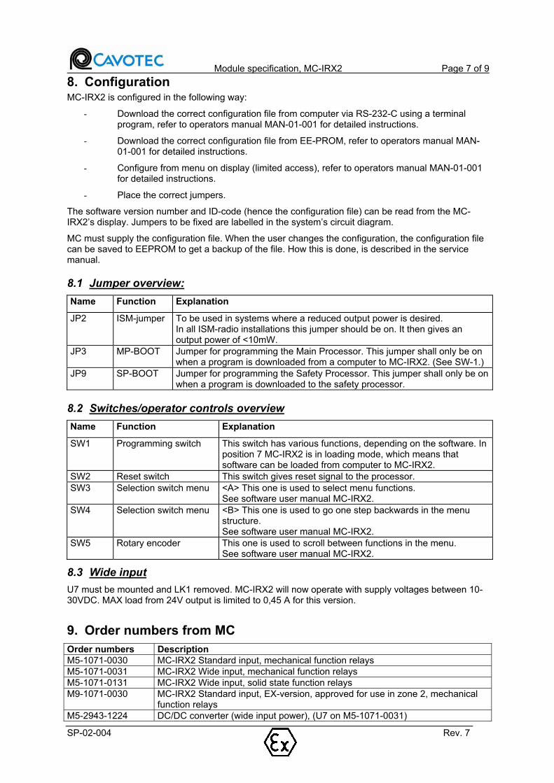
8. Configuration MC-IRX2 is configured in the following way:
- Download the correct configuration file from computer via RS-232-C using a terminal program, refer to operators manual MAN-01-001 for detailed instructions.
- Download the correct configuration file from EE-PROM, refer to operators manual MAN-01-001 for detailed instructions.
- Configure from menu on display (limited access), refer to operators manual MAN-01-001 for detailed instructions.
- Place the correct jumpers.
The software version number and ID-code (hence the configuration file) can be read from the MC-IRX2’s display. Jumpers to be fixed are labelled in the system’s circuit diagram.
MC must supply the configuration file. When the user changes the configuration, the configuration file can be saved to EEPROM to get a backup of the file. How this is done, is described in the service manual.
8.1 Jumper overview:
Name Function Explanation
JP2 ISM-jumper To be used in systems where a reduced output power is desired. In all ISM-radio installations this jumper should be on. It then gives an output power of <10mW.
JP3 MP-BOOT Jumper for programming the Main Processor. This jumper shall only be on when a program is downloaded from a computer to MC-IRX2. (See SW-1.)
JP9 SP-BOOT Jumper for programming the Safety Processor. This jumper shall only be on when a program is downloaded to the safety processor.
8.2 Switches/operator controls overview
Name Function Explanation
SW1 Programming switch This switch has various functions, depending on the software. In position 7 MC-IRX2 is in loading mode, which means that software can be loaded from computer to MC-IRX2.
SW2 Reset switch This switch gives reset signal to the processor.
SW3 Selection switch menu <A> This one is used to select menu functions. See software user manual MC-IRX2.
SW4 Selection switch menu <B> This one is used to go one step backwards in the menu structure. See software user manual MC-IRX2.
SW5 Rotary encoder This one is used to scroll between functions in the menu. See software user manual MC-IRX2.
8.3 Wide input
U7 must be mounted and LK1 removed. MC-IRX2 will now operate with supply voltages between 10-30VDC. MAX load from 24V output is limited to 0,45 A for this version.
9. Order numbers from MC Order numbers Description M5-1071-0030 MC-IRX2 Standard input, mechanical function relays
M5-1071-0031 MC-IRX2 Wide input, mechanical function relays
M5-1071-0131 MC-IRX2 Wide input, solid state function relays
M9-1071-0030 MC-IRX2 Standard input, EX-version, approved for use in zone 2, mechanical function relays
M5-2943-1224 DC/DC converter (wide input power), (U7 on M5-1071-0031)

Module specification, MC-IRX2 Page 8 of 9
SP-02-004 Rev. 7
Order numbers Description M5-2323-3001 Data cable for programming, DB9F-DB9M 3m
M5-2330-0001 Jumper
Order numbers for other MC-modules connected to MC-IRX2 is specified in the module specification for each module. All order numbers will also be specified in the bill of materials for each delivery.
Flat cables and cables with Micronector-contacts must be order with a specified length.
10. How to install / replace EE-PROM During this operation, you should use electrostatic safety tools as described in the service manual.
- Turn the power off.
- Remove the EE-PROM. Use a suitable extraction tool. Alternatively use a screwdriver, place it between the socket and the EE-PROM and lift carefully. Be careful not to bend the EE-PROM legs.
- To replace an EE-PROM or install a new one, place it in the base and then push it straight down. Take care that the orientation is correct. The mark in the socket and the mark on the EE-PROM shall match.
11. Specifications
11.1 Standard input (M5-1071-0030)
Supply voltage:
+24V terminal (41 and 42): +18VDC - +30VDC
Current consumption
24V terminal (41 and 42): <100 mA All relays deactivated, without radio <330 mA All relays activated, without radio
The current consumption for modules connected to the MC-IRX2 must be added to the above-mentioned figures.
11.1.1 Outputs
Max load at outputs: +24V terminal (48 or 56): 775mA +9V terminal (52): 225mA
11.2 Wide input (M5-1071-0031 and M5-1071-0131)
Supply voltage:+24V terminal (41 og 42): +10VDC - +30VDC
For solid state relay variants, relay input screw terminals 23…38 must be connected to the same power supply source as +24V terminal.
NB! The Solid state variant is not faulty connection secure!
Max current consumption: 10V input to terminal (41 and 42): 1000mA All relays activated, with radio 24V input to terminal (41 and 42): 420 mA All relays activated, with radio
11.2.1 Outputs mechanical function relays
Max load at outputs is limited to 4W. ExampleLoad at +9V terminal (52) = 150mA = 1,35W, thus the load at 24V terminal (48 or 56) is limited to 2,65W = 110mA.

Module specification, MC-IRX2 Page 9 of 9
SP-02-004 Rev. 7
11.2.2 Outputs solid state relays (only M5-1071-0131)
Max load on outputs is 3A.
NB! The Solid state variant is not faulty connection secure! Must be protected with external fuses. All loads must have common earth with MC-IRX2
11.3 EX-version (M9-1071-0030)
The EX-version is approved for use in hazardious areas zone 2. It has the same specifications as the standard input version with the following limitations.
It must be mounted in a EX e-enclousure
No relays (terminals 1-40) must be connected to voltages higher than 65 VAC.
External transient protection is required to prevent the rated voltage beeing exceeded by transients of more than 40%.
11.4 Relay
Load, ESR relay:
Type: Schrack Safety Relay SR2M
Resistive: Max 5A / 0-250 VAC / 0-30 VDC (2A / 30-40VDC, 1A / 40-50VDC) Min 50mW
* EX-version Max 5A / 0-65VAC / 0-50VDC Min 50mW
Load, mechanical function relay:
Type: Schrack PCB Relay PE014
Resistive: Max 5A / 0-240 VAC / 0-30 VDC (2A / 30-40VDC, 1A / 40-50VDC) Min 120mW
* EX-version Max 5A / 0-65VAC / 0-50VDC Min 120mW
Load, Solid State relay:
Type: ST VN750
Max 3A / 0-30 VDC
Manual for MC-3-5-EX, Nemko 08ATEX1426 Page 1 of 7
MAN-08-003 Rev. 3This is a Schedule document, do NOT change without approval from the certification body.
Manual for MC-3-5-EX, Nemko 08ATEX1426
Document number
MAN-08-003
Manual for MC-3-5-EX, Nemko 08ATEX1426 Page 2 of 7
MAN-08-003 Rev. 3This is a Schedule document, do NOT change without approval from the certification body.
Table of Contents 1 Safety notification!......................................................................................................................... 3
2 General information....................................................................................................................... 3
3 Definitions ...................................................................................................................................... 3
4 Documentation of EX-system....................................................................................................... 3
5 Conditions ...................................................................................................................................... 3
6 Specifications of areas.................................................................................................................. 4
7 Classification of the equipment ................................................................................................... 4
8 Marking of the equipment ............................................................................................................. 4
8.1 MC-3-5-EX (Group II) ............................................................................................................... 48.1.1 Base unit............................................................................................................................ 48.1.2 Terminal............................................................................................................................. 5
8.2 MC-3-5-EX-MINING (Group I) .................................................................................................. 68.2.1 Base unit............................................................................................................................ 68.2.2 Terminal............................................................................................................................. 7
9 Operating instructions .................................................................................................................. 7
9.1 Terminal.................................................................................................................................... 79.1.1 Operating the terminal....................................................................................................... 79.1.2 Maintenance and repair..................................................................................................... 89.1.3 Technical data ................................................................................................................... 8
9.2 Base unit................................................................................................................................... 89.2.1 Maintenance and repair..................................................................................................... 89.2.2 Technical data ................................................................................................................... 8

Manual for MC-3-5-EX, Nemko 08ATEX1426 Page 3 of 7
MAN-08-003 Rev. 3
1 Safety notification!
The operator must read and understand the contents of the documents listed and explained in chapter 2.1 and 2.2 before the system is operated. These specific documents contains information of vital importance for safe operation of the system
2 General information
MC-3-5-EX and MC-3-5-EX-MINING are certified by NEMKO (ATEX Certification Body), certificate number Nemko 08ATEX1426.
3 Definitions
MC-3-5-EX Industrial radio remote control approved for use in potentially explosive atmospheres requiring group II equipment (surface industries).
MC-3-5-EX –MINING Industrial radio remote control approved for use in potentially explosive atmospheres requiring group I equipment (mines).
EX-marking Obligatory marking of EX-equipment, giving information about:
Type of protection (e.g. EEx ia)
Group of equipment (e.g. I M1)
Type of atmosphere (G=gas, D=dust) (Only for Group II!)
Gas group (e.g. IIB) (Only for Group II!)
Temperature class (e.g. T4) (Only for Group II!)
4 Documentation of EX-system
The complete documentation of the MC-3-5-EX and MC-3-5-EX-MINING systems includes:
MAN-08-003 Manual for MC-3-5-EX (this document)
EX-certificate(s)
MAN-07-007 MC-3 Series Instruction Manual
Module specifications
Wiring diagram, Bill of materials and configuration settings
Delivery specific manuals
MAN-08-003 describes changes and limitations of the systems relative a standard MC-3-5 system described in MAN-07-007. Thus, MAN-07-007 with its references to a complete MC-3-5 documentation is the basis for a good understanding of this document and finally a completeMC-3-5-EX and MC-3-5-EX-MINING system.
The EX-certificate(s) refer to the directives, standards and documents that form the basis of the approval, any special conditions for use of the system, labelling, type of equipment etc.
5 Conditions
This document takes it for granted that the reader has necessary general knowledge about EX, and especially about working in explosive areas.
This is a Schedule document, do NOT change without approval from the certification body.

Manual for MC-3-5-EX, Nemko 08ATEX1426 Page 4 of 7
MAN-08-003 Rev. 3
6 Specifications of areas
The following specifications of areas are used in this document.
Safe area Area without danger of explosion – that is; an area where spill of explosive gas, vapour or fluid does not occur. In a safe area standard equipment without EX-classification may be used.
Zone 2 / 22
(Only group II)
Explosive area, secondary place of spill. Spill is not expected to occur during normal operation. If spill still occurs it will be of short duration and with low frequency. For example around flanges, couplings, valves etc. In zone 2/22 equipment of category 3, 2 or 1 may be used.
Zone 1 / 21
(Only group II)
Explosive area, primary place of spill. Spill can be expected to occur now and then during normal operation. For example during ventilation of storage tanks, at flexible pipes and hoses, at seals for rotating equipment etc. In zone 1/21 equipment of category 2 or 1 may be used.
Zone 0
(Only group II)
Explosive area, explosive atmosphere is present continuously or long term or frequently. For example inside storage tanks or down in mines. In zone 0 only equipment of category 1 may be used.
7 Classification of the equipment
The table below shows the classification of the different units in a MC-3-5-EX and a MC-3-5-EX-MINING system.
Unit MC-3-5-EX MC-3-5-EX-MININGTerminal Category 1, 2 or 3 M1
Base Unit Not protected or category 2 Not protected
Battery* Category 1, 2 or 3 M1
Battery charger* Not protected Not protected
* MC-3-5-EX and MC-3-5-EX-MINING may also be delivered with cable communication only (without the possibility of radio communication). These systems are delivered without battery charger and without battery.
IMPORTANT!Check the EX-marking on the equipment and verify the classification of the units in your system!
WARNING!Units that are not classified must either be placed in a safe area or it must be placed in an encapsulation that gives the necessary protection.
8 Marking of the equipment
8.1 MC-3-5-EX (Group II)
8.1.1 Base unitThe base unit must either be placed in safe area or it must be protected by other approved protection metods (Ex de for example).
The base unit will be marked as associated apparatus.
This is a Schedule document, do NOT change without approval from the certification body.
Manual for MC-3-5-EX, Nemko 08ATEX1426 Page 5 of 7
MAN-08-003 Rev. 3
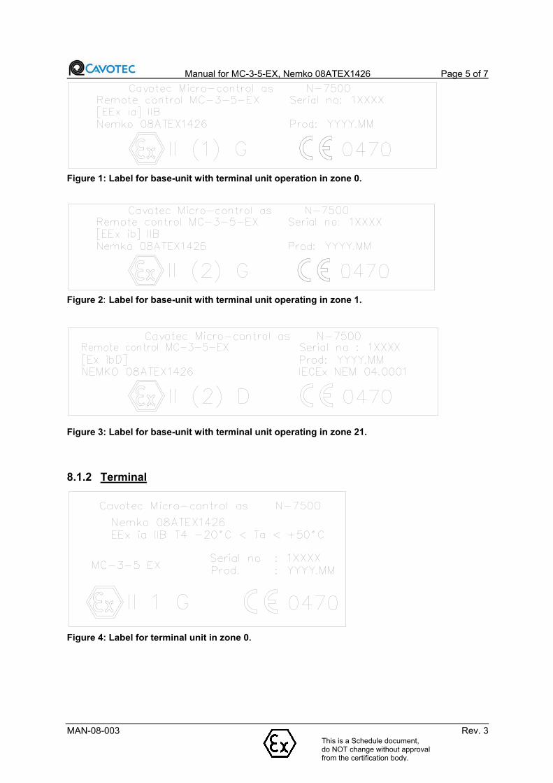
Figure 1: Label for base-unit with terminal unit operation in zone 0.
Figure 2: Label for base-unit with terminal unit operating in zone 1.
Figure 3: Label for base-unit with terminal unit operating in zone 21.
8.1.2 Terminal
Figure 4: Label for terminal unit in zone 0.
This is a Schedule document, do NOT change without approval from the certification body.
Manual for MC-3-5-EX, Nemko 08ATEX1426 Page 6 of 7
MAN-08-003 Rev. 3
Figure 5: Label for terminal unit in zone 1.
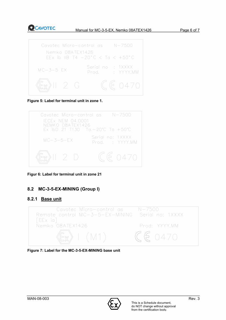
Figur 6: Label for terminal unit in zone 21
8.2 MC-3-5-EX-MINING (Group I)
8.2.1 Base unit
Figure 7: Label for the MC-3-5-EX-MINING base unit
This is a Schedule document, do NOT change without approval from the certification body.

Manual for MC-3-5-EX, Nemko 08ATEX1426 Page 7 of 7
MAN-08-003 Rev. 3
8.2.2 Terminal
Figure 8: Label for the MC-3-5-EX-MINING terminal unit
IMPORTANT!Check the EX-marking on the equipment and verify the classification of the units in your system!
WARNING!Units that are not classified must either be placed in a safe area or it must be placed in an encapsulation that gives the necessary protection.
9 Operating instructions
Except for the limitations and warnings given in this chapter the MC-3-5-EX and MC-3-5-EX-MINING is used as the MC-3-5, see MAN-07-007 ” MC-3 Series Instruction Manual”.
9.1 Terminal
9.1.1 Operating the terminal
WARNING!The terminal must not be used in zones for which it is not approved.
Batteries for zone 0, 1, 2, 21, 22 and M1 are intrinsic safe, and may be removed from/put in the terminal with an explosive atmosphere present. The battery pack has a unique design to avoid replacement of non-certified battery pack, and polarity reversal. The type of protection Exi will not be invalidated by polarity reversal of the cable connection or the battery.
MC-3-5-EX and MC-3-5-EX-MINING may also be delivered with cable communication only (without the possibility of radio communication). These systems are delivered without battery charger and without battery.
The battery should be removed from the terminal when cable communication is used. The cable connects the terminal with the base unit and serves both as power supply and communication line. The cable is connected to an EX barrier in the base unit and gives intrinsic safe signal to the terminal.
This is a Schedule document, do NOT change without approval from the certification body.
Manual for MC-3-5-EX, Nemko 08ATEX1426 Page 8 of 7
MAN-08-003 Rev. 3
9.1.2 Maintenance and repair
WARNING!If encapsulation, battery fastening, switches, joysticks, or similar are damaged, this must be repaired before the equipment is put into use.
WARNING!As a regulation (ET-72) and instructions exist regarding maintenance and repairs etc. (NEMKO EXR-01), the owner/user should contact Cavotec Micro-control as to decide what repairs the owner/user can do on his own, and what repairs must be done by the manufacturer/authorized personnel.
9.1.3 Technical data
Physical size: MC-3-5 230x175x160mm
Weight: 2-3 kg (The weight will vary with the terminal's equipment.)
Operating voltage: 7.2 VDC
Supplementary specifications are given in the enclosed module specifications.
9.2 Base unit
9.2.1 Maintenance and repair
IMPORTANT!As a regulation (ET-72) and instructions exist regarding maintenance and repairs etc. (NEMKO EXR-01), the owner/user should contact Cavotec Micro-control as to decide what repairs the owner/user can do on his own, and what repairs must be done by the manufacturer/authorized personnel.
IMPORTANT!Encapsulations for use in an explosive area demand regular supervision/inspection. Cleaning of the encapsulation is an important part of the maintenance, among other things to avoid corrosion. When using cleaning remedies care must be taken, so that the equipment’s corrosion preventing coating is not damaged. Cleaning also helps to maintain the equipment’s temperature class. Use a moist cloth when cleaning.
9.2.2 Technical dataAll base units are produced according to the customer’s specifications, the enclosed wiring diagram shows how the base unit is connected.
The operating voltage will vary for each delivery, the correct operating voltage is stated on the enclosed wiring diagram and on a label of the base unit.
Physical size and weight of the enclosure will vary for each delivery.
Supplementary specifications are given in the enclosed module specifications.
This is a Schedule document, do NOT change without approval from the certification body.

MC!3 Series
Instruction Manual Instruction Manual
MC!3 Series
Radio Remote Control Systems
MC!3!4
MC!3!5
MC!3!6
MC!3000
MC!3200
MC!3000+
MC!3300
Wesselsv 2, 7500 Stjørdal, Norway E!mail: [email protected]
Tel.: + 47 74 83 98 60 www.cavotec.com
Contents
1. Introduction
2. Description
3. Functional Description
4. Main Data.
5. Installation
6. Operation
7. Battery Charger and Batteries
8. Maintenance
9. Safety Compliances
Safety Notes
Inspect the MC!3 series equipment before using it.
Check for any damage that may be incurred during shipping.
Do not open the housing. There are no user serviceable parts.
Do not use the device if it appears to be damaged.

Use only recommended batteries.
Avoid shock and vibrations if possible.
Avoid high temperature.
Do not immerse in water.
ENSURE THAT THE SUPPLY VOLTAGE IS CORRECT.
INSTALLATION SHOULD ONLY BE CARRIED OUT BY QUALIFIED PERSONNEL.
Cavotec Micro!control AS reserves the right to make improvements and/or changes in the
products and/or specifi cations described in this information at any time without notice.
1. Introduction
The equipment of the MC!3 series is designed for use in harsh industrial environment to control
machinery such as overhead cranes, hoists, recovery vehicles, concrete pumps, sludge trucks etc.
The remote controls use joysticks, pushbuttons and toggle switches to control the designated
equipment.
As the different remote control models vary according to customer requirements, this manual describes
only functions that are common for all MC!3 series deliveries. For customer!specific systems please refer
to applied documentation.
1.1 Marking
®

MC!3!5
The serial number is found on the backside of the respective unit.
(cont.)
1.1 Marking (cont.)
Base unit
MC!3300
2. Description
The system consists of a terminal (remote control), with a carrying belt or neck strap, batteries, a base
unit with an antenna and a battery charger. Some models are equipped with a cable. As customer
specifications vary greatly, the terminal comes in different models which differ in configuration, size and
weight. The graphic below shows two typical examples of a terminal.
Terminal ! example 1
Contains the pushbuttons, joysticks, toggle switches and LED indicator lamps. The terminal is carried by
the operator with a belt or a neck strap.
Example for models
MC!3000
MC!3000+
MC!3300

Cable (optional)
Connects the terminal with the base unit and serves both as power supply and communication line.
Base unit
The part of the system connected to the machine or PLC.

Antenna
Located on or connected to the base unit with a coaxial cable. Can be an internal or external type.
External antenna can be mounted on the base unit or some distance away with an extension cable
supplied by Cavotec Micro!control.
Carrying belt/ neck strap
Belt or strap to carry the terminal safely and keep the operator’s hands free. Should be used whenever
the terminal is being operated for safety and comfort.
Failure to use the belt or strap may cause injury as you will not have proper control of the terminal.
Terminal ! example 2
Example for models
MC!3!4
MC!3!5
MC!3!6
3. Functional Description
The remote control communicates by radio signals or by cable, with the base unit which is installed on
the designated equipment.
3.1 Signal Encoding
Unique encoding of the radio signal prevents unintentional operation caused by interference from other
radio systems.
3.2 Feedback
If configured the operator can read information from the machine at the operator terminal. The
information could include e.g. % of load, rpm, torque, speed, text instruction, etc.
3.3 Operating Range
Depending on the installation the operating range can be from 100!1000m. The range may change
according to the surroundings and other equipment.
3.4 Base Unit
Refer to system specific data.
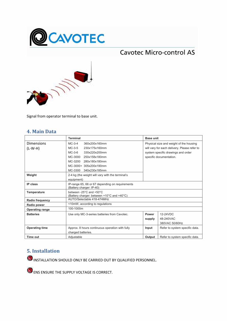
Signal from operator terminal to base unit.
4. Main Data
Terminal Base unit
Dimensions
(L!W!H)
MC-3-4 360x200x160mm
MC-3-5 230x175x160mm
MC-3-6 330x220x200mm
MC-3000 250x158x180mm
MC-3200 280x180x180mm
MC-3000+ 305x200x190mm
MC-3300 340x230x185mm
Physical size and weight of the housing
will vary for each delivery. Please refer to
system specific drawings and order
specific documentation.
Weight 2-4 kg (the weight will vary with the terminal’s
equipment)
IP class IP-range 65, 66 or 67 depending on requirements (Battery charger: IP-40)
Temperature between -25°C and +50°C (Battery charger: between +10°C and +40°C)
Radio frequency AUTO/Selectable 418-474MHz
Radio power <10mW, according to regulations
Operating range 100-1000m
Batteries Use only MC-3-series batteries from Cavotec. Power
supply
12-24VDC
48-240VAC
380VAC 50/60Hz
Operating time Approx. 8 hours continuous operation with fully
charged batteries.
Input Refer to system specific data.
Time out Adjustable Output Refer to system specific data.
5. Installation
INSTALLATION SHOULD ONLY BE CARRIED OUT BY QUALIFIED PERSONNEL.
ENS ENSURE THE SUPPLY VOLTAGE IS CORRECT.

Consider the ambient temperature and IP rating.
If the installation is subject to harsh vibrations use isolating mountings available from Cavotec
Micro!control AS.
5.1 Installing the Base Unit
1) Fasten the base unit securely onto a suitable part of the machine or equipment being controlled.
a) Install if possible, in direct line of sight with the operator.
b) Ensure that the base unit is installed where it will not be conflicting with moving parts in
operation.
2) Reserve space around the unit to ensure easy removal of the lid/opening of the door and easy
access to the connectors and buttons in the base unit.
Connect the base unit according to the system specific drawings.
5.2 Installing the Antenna
The best location for the antenna is somewhere in free space, and with a free line to the operator’s
position.
Take care that the antenna will not be damaged by moving machinery.
Do not mount the antenna inside a metal enclosure.
6. Operation
6.1 Operation of Terminal
MC!3 series terminals are produced to control a variety of equipment. Specific instructions are not given
here. It is important that the operator is familiar with the machine being controlled and has been given
the necessary training.
Start
Check that a fully charged battery is in the terminal. Pull out/twist the Emergency Stop button and turn
the terminal ON. Press the Start button if fitted.
After a self test (approx. 1 sec.) the terminal will establish contact with the base unit.
Stop and Emergency Stop
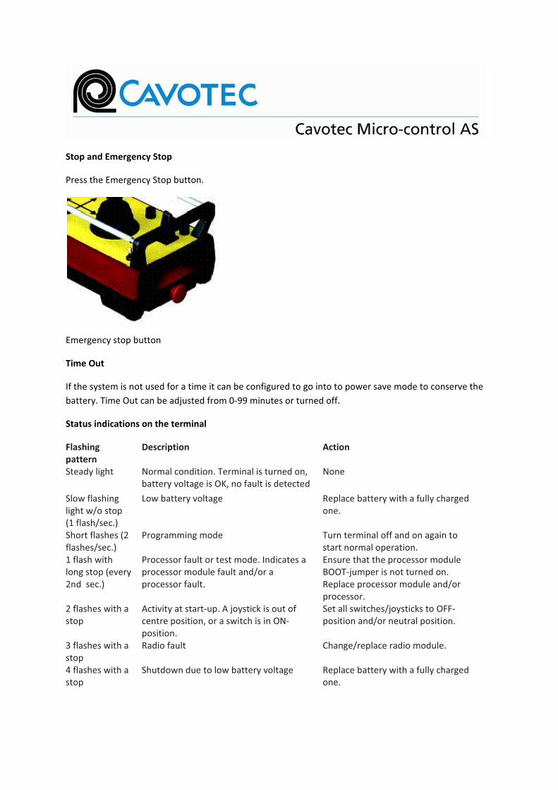
Press the Emergency Stop button.
Emergency stop button
Time Out
If the system is not used for a time it can be configured to go into to power save mode to conserve the
battery. Time Out can be adjusted from 0!99 minutes or turned off.
Status indications on the terminal
Flashing
pattern
Description Action
Steady light Normal condition. Terminal is turned on,
battery voltage is OK, no fault is detected
None
Slow flashing
light w/o stop
(1 flash/sec.)
Low battery voltage Replace battery with a fully charged
one.
Short flashes (2
flashes/sec.)
Programming mode Turn terminal off and on again to
start normal operation.
1 flash with
long stop (every
2nd sec.)
Processor fault or test mode. Indicates a
processor module fault and/or a
processor fault.
Ensure that the processor module
BOOT!jumper is not turned on.
Replace processor module and/or
processor.
2 flashes with a
stop
Activity at start!up. A joystick is out of
centre position, or a switch is in ON!
position.
Set all switches/joysticks to OFF!
position and/or neutral position.
3 flashes with a
stop
Radio fault Change/replace radio module.
4 flashes with a
stop
Shutdown due to low battery voltage Replace battery with a fully charged
one.

5 flashes with a
stop
Keyboard fault. Terminal is not able to
”read” switches, joysticks etc.
There is a fault at the input module.
6 flashes with a
stop
Shutdown due to inactivity. The terminal
will soon ”turn itself off” since no
switches, joysticks etc. have been
activated.
Turn terminal off and on again to
start normal operation.
7 flashes with a
stop
Priority stop. Stop button or shock
detector have been activated.
Ensure stop button is out and turn
terminal OFF and ON again to start
normal operation.
Short flashes at
the battery light
Terminal in programming mode Min/Max programming of analog
functions
No LED Ensure terminal contains a charged
battery and is turned on. If the
terminal has turned itself off due to
inactivity, turn it off and on again to
start normal operation.
6.2. MIN/MAX programming of analog functions
Adjustment procedure:
1. Turn the terminal off.
2. Press the PROGRAM buttons MIN and MAX at the same time.
3. Turn the terminal on.
4. Release the PROGRAM buttons MIN and MAX. The terminal is now in programming mode,
indicated with short flashes at the battery light. If the terminal has a LED!display, this will show
A!00, indicating programming mode. When a function is being programmed the display shows:
A!XX where XX shows which analog channel is being programmed, and is a number between
01….13.
5. Adjustment:
Move the function at your choice to adjust until you get the wanted response. If this shall be
your minimum response, press MIN. If this shall be your maximum response, press MAX. The
terminal will then automatically adjust the increase of the response so that the whole area of
the joystick is between the two chosen points.
6. Each function is adjusted separately for each direction (up/down/right/left).

7. Reset:
Move the function you select to reset out from the center. Press MIN and MAX at the same
time.
The function is now reset.
8. When the programming is finished the transmitter must be turned off and on again to start in
normal mode.
6.3. Operation of Base Unit
All the MC!3!series base units are produced according to customer specifications, the wiring diagram
shows how the base unit is connected.
If the base unit does not operate correctly, check the LED indication and display for messages, see
below.
All repairs must be carried out by a rep! resentative from Cavotec Micro!control AS.
Possible indications in the base unit
During normal operation, the display is divided into three fields, an upper line, the status and the timer.
Base unit display when there is no communication with the terminal.
Base unit display when the operator terminal is switched on.
When a fatal (non recoverable) error occurs, the display shows:
<msg> is a text describing the cause. Turn the supply Off and On. If the message reappears, the main
board is faulty and needs replacing.
The display is also used for a menu system allowing viewing of all operational parameters and service
information.

The timer field shows the time elapsed since the last change of operational mode
(online/passive/idle/locked/blocked) in hours, minutes and seconds:
01:43:12
Indications in the upper line:
[Error: E003] Failure in radio module.
[Error: E010] Aux port communication error.
[Error: E011] MUS bus communication error.
[Micro!control as] No communication with a terminal and no onboard
relays active.
[..3......0......] Shows activated relays, in this case relays #3 and #10.
Indications in the status field:
A4:!30% Most active analogue output. In this case channel 4 with output value of !30% .
Online Base unit communicates with a terminal and E!stop is active.
Passive Base unit communicates with a terminal, but E!stop relay is inactive. May be caused
by too low supply voltage.
Idle Base unit does not communicate with a terminal.
Locked Base unit does not communicate and does not search for additional terminals (first
come first serve mode).
Blocked Base unit communicates with a terminal and E!stop is inactive due to active stop or
softplc function.
7. Battery Charger and Batteries
The operating time for a fully charged battery is approximately 8 hours. The rechargeable battery has a
lifetime of approximately 1000 charging cycles or 2!3 years. These times can vary according to usage,
system specifications and ambient temperature.
Risk of electric shock if used incorrectly.
Do not use the device if it appears to be damaged.

The battery charger is intended for indoor use only. Keep away from high humidity and heat.
7.1 Changing the Battery
Use only batteries provided by Cavotec Micro!control AS.
1. Put the machine being controlled in to a safe position.
2. Turn the terminal OFF.
3. Remove the battery and insert a fully charged one.
4. Turn the terminal ON.
5. Terminals with 2 batteries fitted can continue to operate, replace only one battery at a time.
7.2 Battery Charger Installation and Use
Use only the battery charger supplied with the system or a replacement from Cavotec Micro!control
AS.
1. Install the battery charger in a clean and dry environment (+10°C to +40°C).
2. Connect the charger to the correct supply voltage.
3. Insert the battery to be charged.
4. Wait to see the indication that charging is normal. An indicator shows when the battery is
charged.
5. Leave the battery in the charger until it is required for use.
6. Batteries not in constant use should be charged at least once every 2 months.
7.3 Disposing of the Batteries
Batteries are hazardous waste and must not be disposed of with normal rubbish. You should dispose
of the batteries according to local laws and rules, or return them to Cavotec Micro!control AS.
7.4 Power Supply (if applicable)
Some terminal models are equipped with a cable and batteries and some with only a cable. The cable is
connected to the base unit and serves as both power supply and communication line to the base unit.
For models with both radio function and cable, the radio mode is deactivated as soon as the cable is
connected. The terminal and the base unit then communicate via the cable.
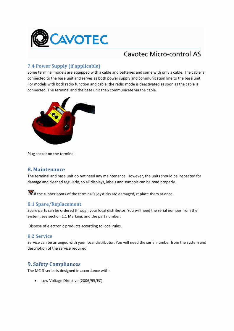
Plug socket on the terminal
8. Maintenance
The terminal and base unit do not need any maintenance. However, the units should be inspected for
damage and cleaned regularly, so all displays, labels and symbols can be read properly.
If the rubber boots of the terminal’s joysticks are damaged, replace them at once.
8.1 Spare/Replacement
Spare parts can be ordered through your local distributor. You will need the serial number from the
system, see section 1.1 Marking, and the part number.
Dispose of electronic products according to local rules.
8.2 Service
Service can be arranged with your local distributor. You will need the serial number from the system and
description of the service required.
9. Safety Compliances
The MC!3!series is designed in accordance with:
Low Voltage Directive (2006/95/EC)

EMC Directive (2004/108/EC)
Machinery Directive (2006/42/EC)
R&TTE Directive (99/5/EC)
Further standards and certificates may be included depending on the application.
The system is certified according to the Federal Communications Commission rules Part 90 sub clause
217. To maintain the distance of 20 cm from the body to the antenna as required in the rules the
terminal should only be used with the carrying belt.
9.1 Warranty
All the deliveries are thoroughly tested and packed before they leave Cavotec Micro!control AS. If the
delivery is found to be damaged when it is opened, inform the carrier immediately. Cavotec Micro!
control AS does not cover any damages caused during transport.
All systems are delivered warranted against material and manufacturing faults. The warranty covers
repairs authorised by Cavotec Micro!control. Expenses for service outside Cavotec Micro!control AS are
not included.
Repairs done without authority from Cavotec Micro!control AS may invalidate any warranty.
Information in this document is subject to change without notice.
© 2010 Cavotec Micro!control.
All rights reserved.

Manual for MC-3000-EX, IECEx NEM 04.0001 Page 1 of 7
MAN-04-004 Rev. 5This is a Schedule document, do NOT change without approval from the certification body.
Manual for MC-3000-EX, IECEx NEM 04.0001
Document number
MAN-04-004
Manual for MC-3000-EX, IECEx NEM 04.0001 Page 2 of 7
MAN-04-004 Rev. 5This is a Schedule document, do NOT change without approval from the certification body.
Table of Contents
1 Safety notification! ............................................................................................. 3
2 General information ........................................................................................... 3
3 Definitions........................................................................................................... 3
4 Documentation of EX-system............................................................................ 3
5 Conditions .......................................................................................................... 3
6 Specifications of areas ...................................................................................... 4
7 Marking of the equipment.................................................................................. 4
7.1 MC-3-5-EX/3-6-EX/3000-EX (Group II) .......................................................... 47.1.1 Base unit .................................................................................................. 47.1.2 Terminal ................................................................................................... 5
7.2 MC-3-5-EX/3-6-EX/3000-EX-MINING (Group I) ............................................. 67.2.1 Base unit .................................................................................................. 67.2.2 Terminal ................................................................................................... 6
8 Operating instructions....................................................................................... 6
8.1 Terminal ......................................................................................................... 68.1.1 Operating the terminal .............................................................................. 68.1.2 Maintenance and repair............................................................................ 78.1.3 Technical data .......................................................................................... 7
8.2 Base unit ........................................................................................................ 78.2.1 Maintenance and repair............................................................................ 78.2.2 Technical data .......................................................................................... 7

Manual for MC-3000-EX, IECEx NEM 04.0001 Page 3 of 7
MAN-04-004 Rev. 5
1 Safety notification!
The operator must read and understand the contents of the documents listed and explained in chapter 2.1 and 2.2 before the system is operated. These specific documents contains information of vital importance for safe operation of the system
2 General information
MC-3-5-EX/3-6-EX/3000-EX and MC-3-5-EX/3-6-EX/3000-EX-MINING are certified by NEMKO (IECEx Certification Body), certificate number IECEx NEM 04.0001.
3 Definitions
MC-3-5-EX/3-6-EX/3000-EXIndustrial radio remote control approved for use in potentially explosive atmospheres requiring group II equipment (surface industries).
MC-3-5-EX/3-6-EX/3000-EX-MINING
Industrial radio remote control approved for use in potentially explosive atmospheres requiring group I equipment (mines).
EX-marking Obligatory marking of EX-equipment, giving information about:
Type of protection (e.g. Ex ia)
Group of equipment (e.g. I )
Gas group (e.g. IIB) (Only for Group II!)
Temperature class (e.g. T4) (Only for Group II!)
4 Documentation of EX-system
The complete documentation of the MC-3-5-EX/3-6-EX/3000-EX and MC-3-5-EX/3-6-EX/3000-EX-MINING systems includes:
MAN-04-004 Manual for MC-3000-EX (this document)
EX-certificate(s)
MAN-07-007 MC-3 Series Instruction Manual
Module specifications
Wiring diagram, Bill of materials and configuration settings
Delivery specific manuals
MAN-04-004 describes changes and limitations of the systems relative a standard MC-3 series system described in MAN-07-007. Thus, MAN-07-007 with its references to a complete MC-3 series documentation is the basis for a good understanding of this document and finally a completeMC-3-5-EX/3-6-EX/3000-EX and MC-3-5-EX/3-6-EX/3000-EX-MINING system.
The EX-certificate(s) refer to the directives, standards and documents that form the basis of the approval, any special conditions for use of the system, labelling, type of equipment etc.
5 Conditions
This document takes it for granted that the reader has necessary general knowledge about EX, and especially about working in explosive areas.
This is a Schedule document, do NOT change without approval from the certification body.
Manual for MC-3000-EX, IECEx NEM 04.0001 Page 4 of 7
MAN-04-004 Rev. 5
6 Specifications of areas
The following specifications of areas are used in this document.
Safe area Area without danger of explosion – that is; an area where spill of explosive gas, vapour or fluid does not occur. In a safe area standard equipment without EX-classification may be used.
Zone 2 / 22
(Only group II)
Explosive area, secondary place of spill. Spill is not expected to occur during normal operation. If spill still occurs it will be of short duration and with low frequency. For example around flanges, couplings, valves etc.
Zone 1 / 21
(Only group II)
Explosive area, primary place of spill. Spill can be expected to occur now and then during normal operation. For example during ventilation of storage tanks, at flexible pipes and hoses, at seals for rotating equipment etc.
Zone 0
(Only group II)
Explosive area, explosive atmosphere is present continuously or long term or frequently. For example inside storage tanks or down in mines.
7 Marking of the equipment
7.1 MC-3-5-EX/3-6-EX/3000-EX (Group II)
7.1.1 Base unitThe base unit must either be placed in safe area or it must be protected by other approved protection metods (Ex de for example).
The base unit will be marked as associated apparatus.
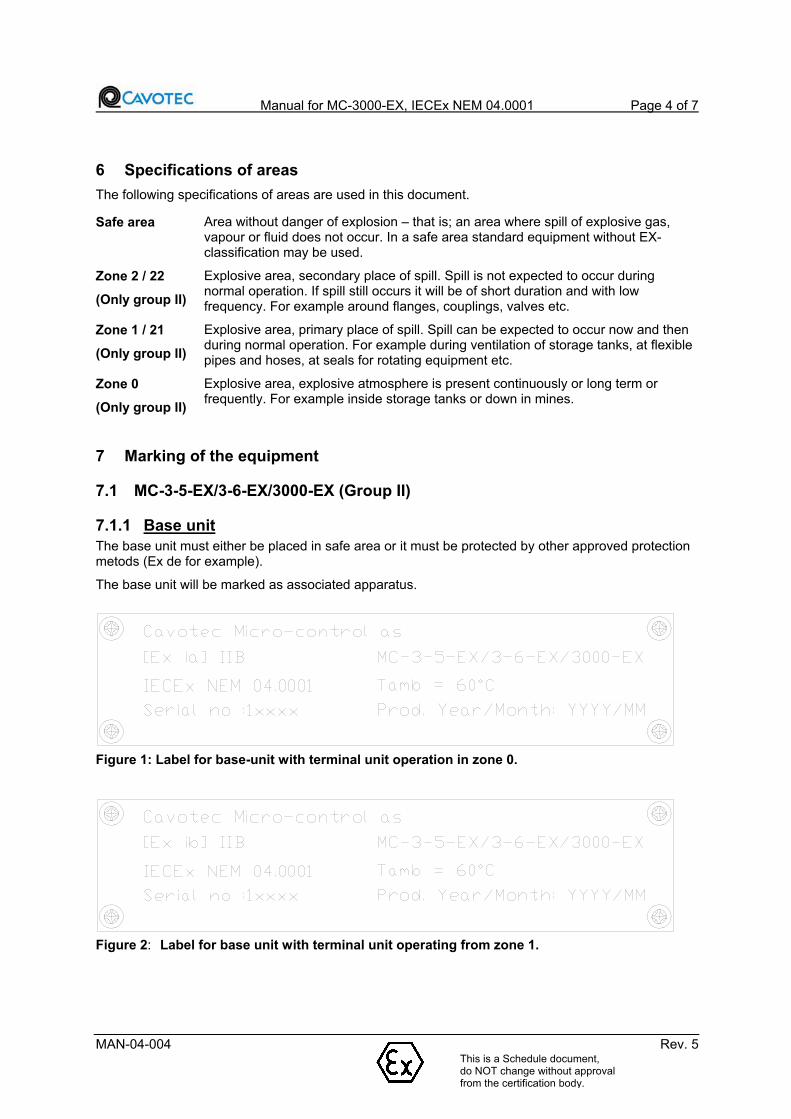
Figure 1: Label for base-unit with terminal unit operation in zone 0.
This is a Schedule document, do NOT change without approval from the certification bod
Figure 2: Label for base unit with terminal unit operating from zone 1.
y.

Manual for MC-3000-EX, IECEx NEM 04.0001 Page 5 of 7
MAN-04-004 Rev. 5
Figure 3: Label for base unit with MC-3-5 EX terminal unit operating from zone 21
7.1.2 Terminal
Figure 4: Label for terminal unit in zone 0.
Figure 5: Label for terminal unit zone 1.
Figure 6: Label for MC-3-5 EX terminal unit zone 21
This is a Schedule document, do NOT change without approval from the certification body.
Manual for MC-3000-EX, IECEx NEM 04.0001 Page 6 of 7
MAN-04-004 Rev. 5
7.2 MC-3-5-EX/3-6-EX/3000-EX-MINING (Group I)
7.2.1 Base unit
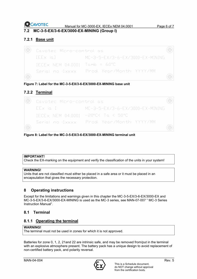
Figure 7: Label for the MC-3-5-EX/3-6-EX/3000-EX-MINING base unit
7.2.2 Terminal
Figure 8: Label for the MC-3-5-EX/3-6-EX/3000-EX-MINING terminal unit
IMPORTANT!Check the EX-marking on the equipment and verify the classification of the units in your system!
WARNING!Units that are not classified must either be placed in a safe area or it must be placed in an encapsulation that gives the necessary protection.
8 Operating instructions
Except for the limitations and warnings given in this chapter the MC-3-5-EX/3-6-EX/3000-EX andMC-3-5-EX/3-6-EX/3000-EX-MINING is used as the MC-3 series, see MAN-07-007 ” MC-3 Series Instruction Manual”.
8.1 Terminal
8.1.1 Operating the terminal
WARNING!The terminal must not be used in zones for which it is not approved.
Batteries for zone 0, 1, 2, 21and 22 are intrinsic safe, and may be removed from/put in the terminal with an explosive atmosphere present. The battery pack has a unique design to avoid replacement of non-certified battery pack, and polarity reversal.
This is a Schedule document, do NOT change without approval from the certification body.

Manual for MC-3000-EX, IECEx NEM 04.0001 Page 7 of 7
MAN-04-004 Rev. 5
The type of protection Exi will not be invalidated by polarity reversal of the cable connection or the battery.
MC-3-5-EX/3-6-EX/3000-EX and MC-3-5-EX/3-6-EX/3000-EX-MINING may also be delivered with cable communication only (without the possibility of radio communication). These systems are delivered without battery charger and without battery.
The battery should be removed from the terminal when cable communication is used. The cable connects the terminal with the base unit and serves both as power supply and communication line. The cable is connected to a EX barrier in the base unit and gives intrinsic safe signal to the terminal.
8.1.2 Maintenance and repair
WARNING!If encapsulation, battery fastening, switches, joysticks, or similar are damaged, this must be repaired before the equipment is put into use.
WARNING!As a regulation (ET-72) and instructions exist regarding maintenance and repairs etc. (NEMKO EXR-01), the owner/user should contact Cavotec Micro-control as to decide what repairs the owner/user can do on his own, and what repairs must be done by the manufacturer/authorized personnel.
8.1.3 Technical dataThe MC-3000 terminal is delivered in two different sizes the biggest version is called MC-3000+. Physical size: MC-3000 250x158x180mm MC-3000+ 305x200x190mm MC-3-5 230x175x160mm MC-3-6 330x220x200mm Weight: 2,5-4 kg (The weight will vary with the terminal's equipment.) Operating voltage: 7.2 VDC
Supplementary specifications are given in the enclosed module specifications.
8.2 Base unit
8.2.1 Maintenance and repair
IMPORTANT!As a regulation (ET-72) and instructions exist regarding maintenance and repairs etc. (NEMKO EXR-01), the owner/user should contact Cavotec Micro-control as to decide what repairs the owner/user can do on his own, and what repairs must be done by the manufacturer/authorized personnel.
IMPORTANT!Encapsulations for use in an explosive area demand regular supervision/inspection. Cleaning of the encapsulation is an important part of the maintenance, among other things to avoid corrosion. When using cleaning remedies care must be taken, so that the equipment’s corrosion preventing coating is not damaged. Cleaning also helps to maintain the equipment’s temperature class. Use a moist cloth when cleaning.
8.2.2 Technical dataAll base units are produced according to the customer’s specifications, the enclosed wiring diagram shows how the base unit is connected.
This is a Schedule document, do NOT change without approval from the certification body.

Manual for MC-3000-EX, IECEx NEM 04.0001 Page 8 of 7
MAN-04-004 Rev. 5This is a Schedule document, do NOT change without approval from the certification body.
The operating voltage will vary for each delivery, the correct operating voltage is stated on the enclosed wiring diagram and on a label of the base unit.
Physical size and weight of the enclosure will vary for each delivery.
Supplementary specifications are given in the enclosed module specifications.

Micro-control as Analogue output adjustment MC-IRX2 Page 1 of 9
MAN-04-002 Rev. 1
Analogue output adjustment MC-IRX2
Document number
MAN-04-002
Revision 1
Date 2004-01-26
Prepared by THH
Checked by
Approved by
Path G:\04\MAN\MAN-04-002-01 Analogue output adjustment MC-IRX2.doc

Micro-control as Analogue output adjustment MC-IRX2 Page 2 of 9
MAN-04-002 Rev. 1
1. General
1.1 Purpose
This document describes the analogue tuning functionality of the BDI000 software.
1.2 Revision history
This is the first revision.
2. Menu system Chapter 4.1, for complete list of menu entries.
2.1 The menu on MC-IRX2 with BDI000 Software
The MC-IRX2 contains a rotary switch and two pushbuttons located below the LCD display. These controls may be used to activate the menu system.
The menu system is organized as a tree structure with up to 7 levels. This example shows how to navigate in the menu system: 1. Start the menu system by pushing button A. 2. Select top menu entry by rotating the rotary switch. 3. Jump to the next menu level by pushing button A again. 4. Select sub menu entry by rotating the rotary switch. 5. Jump back to the top menu level by pushing button B. 6. Jump back to the main screen by pushing button B.
2.2 Parameter editing
To edit a parameter:
1) Go to the menu entry showing the parameter as described in chapter 3..2) Press and hold down the A button while turning the rotary switch until the desired value is
shown. This operation requires the use of both hands. 3) Release A button and the new parameter value is stored to RAM. 4) New / altered settings, can be tested without saving to RAM, by using
menu [33 :Test Edit], The values will return to previous / old settings on next booting of
IRX25) To store the parameters permanently into flash, go to menu [31 :Save Edit], and change
this parameter to 1. The MC-IRX2 then automatically reboots, stores the parameter set to flash and resumes normal operation.
When editing the parameters, be aware of the following:
To avoid accidental altering of the parameters, simply avoid turning the rotary switch while holding down button A.
If the lower LCD line shows [Not allowed ] when pressing the A button, this means that the
parameter is protected by an access code. See next chapter.
When the tuning is completed, the parameters should be saved to flash. If this is forgotten, the system will revert to the last saved parameter set during the next power up.
The parameters are overwritten when downloading new basic software or new setup file.

Micro-control as Analogue output adjustment MC-IRX2 Page 3 of 9
MAN-04-002 Rev. 1
2.3 Access codes
Most parameters may be protected by access codes. This means that the operator has to enter this access code using the menus under top menu [2 :Access codes]. The access code for
analogue tuning is at sub menu [22 :Ana. Tuning]..
When entering one of these menus, the lower LCD line will show one of: [Blocked ] This function is blocked, and the operator is not allowed to alter the value.
Contact micro-control to get a new parameter file with the new values. [Allowed ] The operator is allowed to change the parameters protected by this code. [00-00-00-00 ] The parameters are protected by an access code. Enter the correct code
by holding down the A button while rotating the rotary switch. When the correct code has been entered, the lower line changes to [Allowed ]
3. Analogue output tuning The analogue output tuning is handled at menu entry 6. sub menu 60 for analogue output channel A0_1, sub menu 61 for analogue output channel A1_1………….6F for output A7_2.
Example for output channel A0_1. Menu entry 6, sub menu 60.
Sub menu no. 600: A0_1 MIN + Set minimum positive movement of the output value for channel, in 0-100%
601: A0_1 MAX + Set maximum positive movement of the output value for channel, in 0-100%
602: A0_1 MIN - Set minimum negative movement of the output value for channel, in 0-100%
603: A0_1 MAX + Set maximum negative movement of the output value for channel, in 0-100%
604: A0_1 CURVE Set curve form in the range 1-99, 1-49: soft movement, where 1 is the softest. 50: linear movement, 51-99: Hard movement, where 99 is the hardest. (fig1)
605: A0_1 RAMP Set the ramp time from full speed to full stop in 100ms increments.
606: A0_1 D.PER Dither frequency in 2,5 increments. value 0-127, 0 disables dithering.
607: A0_1 D.AMPL. Dither amplitude in 0-100%, for channels without dithering 0=Normal,1=Inverted (changes direction of movement).
1-49: soft 50: Linear 51-99: Hard
fig1.

Micro-control as Analogue output adjustment MC-IRX2 Page 4 of 9
MAN-04-002 Rev. 1
4. Example Softer start and inverted output on analogue channel A0_1.
1) Start with IRX2 in “Idle”
2) Push button “A” [ 1: System ]
3) Turn rotary switch CW [ 2: Access code ]
4) Push button “A” [ 20: Sys. param ]
5) Turn rotary switch CW [ 22: Ana. Tuning ]
6) Enter Access code [ 00-00-00-00 ]
If Access code is correct the display changes to Access Allowed
7) Push Button “B” [ 2: Access code ]
8) Turn rotary switch CW [ 6: Ana. Tuning ]
9) Push button “A” [ 60: Channel A0_1 ]
10) Push button “A” [ 600: A0_1 MIN+ ]
11) Turn rotary switch CW [ 604: A0_1 Curve ]
12) Push and hold button “A”, and turn rotary switch until desired value. 1-49 soft start.
13) Release button “A” [ 604: A0_1 Curve ]
14) Turn rotary switch CW [ 607: A0_1 D.ampl ]
15) Push and hold button “A”, Turn rotary switch CW, the 2nd line on the display
Changes from [ 0(%) ] to [ 1(%) ]. 0=Normal, 1=Inverted
16) Release button “A”
17) Push button “B” until display shows [ Setup alterd ]
18) Pushbutton “A” [ 1: System ]
19) Turn rotary switch CW [ 3: Setupfile ]
20) Push button “A” [ 30: PC->IRX ]
21) Turn rotary switch CW [ 31: Save edit ]
22 ) Push and hold button “A”, Turn rotary switch CW, the 2nd line on the display
Changes from [ 0=No ] to [ 1=Yes ]
23) Release button “A” [ Flashing ]
24) back to normal operation [ Idle ]
8
2
7
4
4
4
3
2
2
2
1
2
5
2
3
2
4
2
6
4
1
4
231 2 4 5 6 7
493
7
3
2
3
0
2
9
2
8
3
1
3
5
3
4
3
3
3
6
4
0
3
9
3
84645 4847 545150 5352 5655
109 11
1
2
1
5
1
4
1
3
1
6
1
7
2
0
1
9
1
8
RESET
A
SP_BOOT
B
MP_BOOT
M
C
-
2
W
I
R
E
PROG.
SELECT.
J8 P1 J9
SW2 SW1
SW5SW3 SW4
A B
J13
J16
J15 J11 J7
J12 J17 J1 J2 J3 J4 J5 J6
6 543
2
10
F
87
A
9
SW1
EDCB
J3
J4 J2
APP:
7
8
9
10
1
2
3
4
5
6
J1
ORD.NO:
MC-PLL-440C
!"
"#$
%
Freq.band:
Micro-control as Analogue output adjustment MC-IRX2 Page 5 of 9
MAN-04-002 Rev. 1
Rotary switch Button “A” Button “B”

Micro-control as Analogue output adjustment MC-IRX2 Page 6 of 9
MAN-04-002 Rev. 1
4.1 MENU TREE FOR BDI000
1: SYSTEM 10: RUN TIMERS 100: RUNTIMER 1 Shows runtimer 1 values (controlled by SoftPlc)
107: RUNTIMER 8 Shows runtimer 1 values (controlled by SoftPlc)
108: RUNCOUNTER 1 Shows runcounter 1 values (controlled by SoftPlc)
10F: RUNCOUNTER 8 Shows runcounter 8 values (controlled by SoftPlc)
11: DIGITAL VIEW 110: STATUS 1
111: STATUS 2
112: INPUT BUS
113: ROT./PROGRAM
114: RELÈ 1 - 8 Shows status of all on/off signals from/to SoftPlc
11B: RELÈ 57 - 64
11C: FUNC. 1 -8 Shows status of all on/off signals from/to SoftPlc
11J: FUNC. 57-64
11K: ADAM 1-8 Shows status of all on/off signals from/to SoftPlc
11N: ADAM 25-32
11O: DOWN 1 - 8 Shows status of all on/off signals from/to SoftPlc
11R: DOWN 25 - 32
11S: MRK. 1 – 8 Shows status of all on/off signals from/to SoftPlc
11V: MRK. 25 - 32

Micro-control as Analogue output adjustment MC-IRX2 Page 7 of 9
MAN-04-002 Rev. 1
12: ANA IN VIEW 120: ANA.UP: A1 Shows value of analogue input signals to SoftPlc
12C: ANA.UP: A13
12D: ANA.IN: ABUS1 Shows value of analogue input signals to SoftPlc
12G: ANA.IN: ABUS4
12H: ANA.MARK: AM1 Shows value of analogue input signals to SoftPlc
12O: ANA.MARK: AM8
13: ANA OUT VIEW 130: ANA OUT: A0_1 Shows value of analogue output signals from SoftPlc
13F: ANA OUT: A7_2
13G: ANA.DOWN: ADI Shows value of analogue output signals from SoftPlc
13N: ANA.DOWN: AD8
14: SYSTEM LOG 140: MESSAGE 1 Shows stored system log entries. x:xx is message age in hours and minutes.
149: MESSAGE 10
15: SELF TEST Starts IRX self test function.
2: ACCESS CODES 20: SYS.PARAM Enables entry of system parameter access code.
21: FUNC. PARAM Enables entry of function parameter (including SoftPlc) access code.
22: ANA. TUNING Enables entry of analogue tuning access code.
3: SETUPFILE 30: PC IRX Starts download of setupfile from PC using X-modem on RS232 port.
31: SAVE EDIT Saves parameter/SoftPlc editing to flash.
32: DISCARD EDIT Discards parameter/SoftPlc editing
33: TEST EDIT Tests new parameters without saving to flash.
34: IRX EEPROM Saves setup to onboard EEPROM.
35: EEPROM IRX Reads setup from onboard EEPROM.

Micro-control as Analogue output adjustment MC-IRX2 Page 8 of 9
MAN-04-002 Rev. 1
4: SYS. PARAM 40: RADIO FREQ 400: RADIO F. 1 Radio frequencies scanned by IRX (up to 16).
40F: RADIO F. 16
41: TERMINAL ID 410: TERM. 1 ID Terminal ID's scanned by IRX (up to 8)
417: TERM. 8 ID
42: CABLE T.ID Terminal ID used in cable mode.
43: UNIT CODE System unit code. Normally set to 0.
44: FREQ.PER.T Number of frequencies to scan for each terminal.
5: FUNC. PARAM 50: PROG. SELECT Program selector value. May be used to control SoftPlc operation.
51: MODULES 510: RX-BUS RELAY Set to 1 if system has relay modules connected to RX-bus.
511: RX-BUS ANA Set to 1 if system has analogue output modules connected to RX-bus.
512: MUS-BUS ANA Set to 1 if system has analogue output modules connected to MUS-bus
513: IRX EEPROM Set to 1 if IRX has onboard EEPROM for storing runtimers/runcounters.
514: RADIO TYPE Radio type code.
52: M.ANA.REF 520: A0 REFERENCE Analogue module reference type for MUS-bus analogue outputs.
527: A7 REFERENCE
53: M.ANA.TYPE 530: A0_1 TYPE Analogue channel output type for MUS-bus analogue outputs.
53F: A7_2 TYPE
54: SAFETY MODE 540: UNS. RELAYS Set to 1 to allow active onboard relays in safe state.
541: UNC. OUTPUTS Set to 1 to allow active RX-bus/MUS-bus outputs in safe state.
55: AUX PORT 550: AUX P. MODE AUX port mode code.
551: SPEED CODE AUX port serial speed code.
552: FORMAT CODE AUX port format code.
553: RS 485 MODE Set to 1 to use RS-485 port. Set to 0 to use RS-232 port.
554: SERIAL TMOUT Serial timeout in milliseconds.
555: WATCHDOG T. Serial watchdog timeout in milliseconds.
556: SMART FIELDS Number of smart ascii fields received on AUX port.

Micro-control as Analogue output adjustment MC-IRX2 Page 9 of 9
MAN-04-002 Rev. 1
557: SMART F.LEN. Length of each smart ascii field received on AUX port.
56: TERMINAL 1 560: T1 DIGI B. Number of digital bytes to receive from terminal 1
561: T1 ANA B. Number of analogue bytes to receive from terminal 1
562: T1 DIGI D.B. Number of digital bytes to send to terminal 1 (0 in simplex mode)
563: T1 ANA D.B. Number of analogue bytes to send to terminal 1 (0 in simplex mode).
564: T1 D.SMART F Number of smart ascii fields to include in each downlink message.
565: T1 D.OK INP. Digital function used to signal downlink OK in smart ascii mode.
5D: TERMINAL 8 5D0: T8 DIGI B.
5D5: T8 D.OK INP.
5E: LOCK TIMOUT Terminal lock timeout in frequency shifting system. 0=forever.
6: ANA TUNING 60: CHANNEL A0_1 600: A0_1 MIN + Minimum positive movement output value for channel A0_1 in %
601: A0_1 MAX + Maximum positive movement output value for channel A0_1 in %
602: A0_1 MIN - Minimum negative movement output value for channel A0_1 in %
603: A0_1 MAX - Maximum negative movement output value for channel A0_1 in %
604: A0_1 CURVE Curve adjustment factor for output channel A0_1. 50=linear.
605: A0_1 RAMP Ramp time for channel A0_1 in 0.1 second increments.
606: A0_1 D.PER Dithering period, analogue output channel A0_1 in 2.5ms increments.
607: A0_1 D.AMPL. Dithering depth, analogue output channel A0_1 in % For channels without dithering: 0=Normal, 1=Inverted
6F: CHANNEL A7_2 6F0: A7_2 MIN +
6F7: A7_2 D.AMPL.
7: PLC PROGRAM 700: LD(…. A.S.O SoftPlc program
7FF: END PROG

Manual for MC-3000-EX, DNV-2003-OSL-ATEX-0087 Page 1 of 7
MAN-03-003 Rev. 5This is a Schedule document, do NOT change without approval from the certification body.
Manual for MC-3000-EX, DNV-2003-OSL-ATEX-0087
Document number
MAN-03-003

Manual for MC-3000-EX, DNV-2003-OSL-ATEX-0087 Page 2 of 7
MAN-03-003 Rev. 5This is a Schedule document, do NOT change without approval from the certification body.
Table of Contents
1. Safety notification! .......................................................................................... 3
2. General information ........................................................................................ 3
2.1 Definitions....................................................................................................... 32.2 Documentation of EX-system......................................................................... 32.3 Conditions ...................................................................................................... 32.4 Specifications of areas ................................................................................... 32.5 Classification of the equipment....................................................................... 4
3. Marking of the equipment............................................................................... 4
3.1 MC-3000-EX (Group II) .................................................................................. 43.1.1 Base unit .................................................................................................. 43.1.2 Terminal ................................................................................................... 5
3.2 MC-3000-EX-MINING (Group I) ..................................................................... 63.2.1 Base unit .................................................................................................. 63.2.2 Terminal ................................................................................................... 6
4. Operating instructions.................................................................................... 6
4.1 Terminal ......................................................................................................... 64.1.1 Operating the terminal .............................................................................. 64.1.2 Maintenance and repair............................................................................ 74.1.3 Technical data .......................................................................................... 7
4.2 Base unit ........................................................................................................ 74.2.1 Maintenance and repair............................................................................ 74.2.2 Technical data .......................................................................................... 7
Manual for MC-3000-EX, DNV-2003-OSL-ATEX-0087 Page 3 of 7
MAN-03-003 Rev. 5
1 Safety notification!
The operator must read and understand the contents of the documents listed and explained in chapter 2.1 and 2.2 before the system is operated. These specific documents contains information of vital importance for safe operation of the system.
2 General information
MC-3000-EX and MC-3000-EX-MINING is certified by ‘Det Norske Veritas’ –DNV. (Notified body 0575), certificate number DNV-2003-OSL-ATEX-0087, in accordance with ATEX-directive (94/9/EC). The quality system is yearly assessed by NEMKO (Notified body 0470), notification NEMKO 99ATEX078Q.
This document shall also be used when the MC-3-6 terminal housing, manufactured in Statkon, is used. In this case “MC-3000-EX” is replaced by “MC-3-6-EX”.
2.1 Definitions
MC-3000-EX Industrial radio remote control approved for use in potentially explosive atmospheres requiring group II equipment (surface industries).
MC-3000-EX-MINING Industrial radio remote control approved for use in potentially explosive atmospheres requiring group I equipment (mines).
EX-marking Obligatory marking of EX-equipment, giving information about:
Type of protection (e.g. EEx ia)
Group of equipment and category (e.g. I M1)
Type of atmosphere (G=gas, D=dust) (Only for Group II!)
Gas group (e.g. IIB) (Only for Group II!)
Temperature class (e.g. T4) (Only for Group II!)
2.2 Documentation of EX-system
The complete documentation of the MC-3000-EX and MC-3000-EX-MINING systems includes:
MAN-03-003 Manual for MC-3000-EX (this document)
Declaration of conformity
EX-certificate(s)
MAN-07-007 MC-3 Series Instruction Manual
Module specifications
Wiring diagram, Bill of materials and configuration settings
Delivery specific manuals
MAN-03-003 describes changes and limitations of the MC-3000-EX and MC-3000-EX-MINING systems relative a standard MC-3000 system described in MAN-07-007. Thus, MAN-07-007 with its references to a complete MC-3 series documentation is the basis for a good understanding of this document and finally a complete MC-3000-EX and MC-3000-EX-MINING system.
The EX-certificate(s) refer to the directives, standards and documents that form the basis of the approval, any special conditions for use of the system, labelling, type of equipment etc.
2.3 Conditions
This document takes it for granted that the reader has necessary general knowledge about EX, and especially about working in explosive areas.
2.4 Specifications of areas
The following specifications of areas are used in this document.
This is a Schedule document, do NOT change without approval from the certification body.

Manual for MC-3000-EX, DNV-2003-OSL-ATEX-0087 Page 4 of 7
MAN-03-003 Rev. 5
Safe area Area without danger of explosion – an area where explosive gas, vapour or fluid does not occur, standard equipment without EX-classification may be used.
Zone 2
(Only group II)
Explosive area, secondary place of spill. Spill is not expected to occur during normal operation. If spill still occurs it will be of short duration and with low frequency. For example around flanges, couplings, valves etc. In zone 2 equipment of category 3, 2 or 1 may be used.
Zone 1
(Only group II)
Explosive area, primary place of spill. Spill can be expected to occur now and then during normal operation. For example during ventilation of storage tanks, at flexible pipes and hoses, at seals for rotating equipment etc. In zone 1 equipment of category 2 or 1 may be used.
Zone 0
(Only group II)
Explosive area, explosive atmosphere is present continuously or long term or frequently. For example inside storage tanks or down in mines. In zone 0 only equipment of category 1 may be used.
2.5 Classification of the equipment
The table below shows the classification of the different units in a MC-3000-EX and a MC-3000-EX-MINING system.
Unit MC-3000-EX MC-3000-EX-MININGTerminal Category 1, 2 or 3 M1
Base unit Not protected or category 2 Not protected
Battery* Category 1, 2 or 3 M1
Battery charger* Not protected Not protected
* MC-3000-EX and MC-3000-EX-MINING may also be delivered with cable communication only
(without the possibility of radio communication). These systems are delivered without battery charger and without battery.
IMPORTANT!Check the EX-marking on the equipment and verify the classification of the units in your system!
WARNING!Units that are not classified must either be placed in a safe area or it must be placed in an encapsulation that gives the necessary protection.
Marking of the equipment
2.6 MC-3000-EX (Group II)
2.6.1 Base unitThe base unit must either be placed in safe area or it must be protected by other approved protection methods (Ex de for example). The base unit will be marked as associated apparatus.
This is a Schedule document, do NOT change without approval from the certification body.

Manual for MC-3000-EX, DNV-2003-OSL-ATEX-0087 Page 5 of 7
MAN-03-003 Rev. 5
Figure 1 Label for base unit with terminal unit operating from zone 1
Figure 2 Label for base unit with terminal unit operating from zone 0
2.6.2 Terminal
Figure 3 Label for terminal unit operating from zone 1
Figure 4 Label for terminal unit operating from zone 0
This is a Schedule document, do NOT change without approval from the certification body.

Manual for MC-3000-EX, DNV-2003-OSL-ATEX-0087 Page 6 of 7
MAN-03-003 Rev. 5
2.7 MC-3000-EX-MINING (Group I)
2.7.1 Base unit
Figure 5 Label for the MC-3000-EX-MINING base unit
2.7.2 Terminal
Figure 6 Label for the MC-3000-EX-MINING terminal unit
IMPORTANT!Check the EX-marking on the equipment and verify the classification of the units in your system!
WARNING!Units that are not classified must either be placed in a safe area or it must be placed in an encapsulation that gives the necessary protection.
3 Operating instructions
Except for the limitations and warnings given in this chapter the MC-3000-EX and MC-3000-EX-MINING is used as the MC-3000, see MAN-07-007 MC-3 Series Instruction Manual.
3.1 Terminal
3.1.1 Operating the terminal
WARNING!The terminal must not be used in zones for which it is not approved.
This is a Schedule document, do NOT change without approval from the certification body.

Manual for MC-3000-EX, DNV-2003-OSL-ATEX-0087 Page 7 of 7
MAN-03-003 Rev. 5This is a Schedule document, do NOT change without approval from the certification body.
Batteries of category 1, 2, 3 and M1 are intrinsic safe, and may be removed from/put in the terminal with an explosive atmosphere present. The batteries are “coded” and it is not possible to put a ordinary battery into a category 1, 2, 3 or M1 terminal.
The battery should be removed from the terminal when cable communication is used. MAN-07-007 MC-3 Series Instruction Manual gives more detailed description of cable communication.
3.1.2 Maintenance and repair
WARNING!If the encapsulation, battery fastening, switches, joysticks, or similar are damaged, this must be repaired before the equipment is put into use.
WARNING!As a regulation (ET-72) and instructions exist regarding maintenance and repairs etc. (NEMKO EXR-01), the owner/user should contact Cavotec Micro-control as to decide what repairs the owner/user can do on his own, and what repairs must be done by the manufacturer/authorized personnel.
3.1.3 Technical dataThe MC-3000 terminal is delivered in two different sizes the biggest version is called MC-3000+. Physical size: MC-3000 250x158x180 mm MC-3000+ 305x200x190 mm MC-3-6 330x220x200 mm Weight: 2,5-4 kg (The weight will vary with the terminal's equipment.) Operating voltage: 7.2 VDC
Supplementary specifications are given in the enclosed module specifications.
3.2 Base unit
3.2.1 Maintenance and repair
IMPORTANT!As a regulation (ET-72) and instructions exist regarding maintenance and repairs etc. (NEMKO EXR-01), the owner/user should contact Cavotec Micro-control as to decide what repairs the owner/user can do on his own, and what repairs must be done by the manufacturer/authorized personnel.
IMPORTANT!Encapsulations for use in an explosive area demand regular supervision/inspection. Cleaning of the encapsulation is an important part of the maintenance, among other things to avoid corrosion. When using cleaning remedies care must be taken, so that the equipment’s corrosion preventing coating is not damaged. Cleaning also helps to maintain the equipment’s temperature class. Use a moist cloth when cleaning.
3.2.2 Technical dataAll base units are produced according to the customer’s specifications, the enclosed wiring diagram shows how the base unit is connected.
The operating voltage will vary for each delivery, the correct operating voltage is stated on the enclosed wiring diagram and on a label of the base unit.
Physical size and weight of the enclosure will vary for each delivery.
Supplementary specifications are given in the enclosed module specifications.
