sinumerik 802d sl pro - milling, control system overview for ... - … · reliable sinamics s120...
TRANSCRIPT

� �Milling
___________________
___________________
___________________
___________________
___________________
___________________
___________________
___________________
___________________
___________________
___________________
___________________
SINUMERIK 802D sl pro
Milling
Control system overview for machine tools' sales people
03/2011
Preface
Introduction 1
System overview 2
Setup functions 3
Program management and user memory
4
Programming 5
Simulation 6
4th axis machining and mold and die
7
Multilingual operator interface
8
Maintenance and diagnostics 9
Ordering data 10
Summary of unique selling points
11
Legal information
Legal information Warning notice system
This manual contains notices you have to observe in order to ensure your personal safety, as well as to prevent damage to property. The notices referring to your personal safety are highlighted in the manual by a safety alert symbol, notices referring only to property damage have no safety alert symbol. These notices shown below are graded according to the degree of danger.
DANGER indicates that death or severe personal injury will result if proper precautions are not taken.
WARNING indicates that death or severe personal injury may result if proper precautions are not taken.
CAUTION with a safety alert symbol, indicates that minor personal injury can result if proper precautions are not taken.
CAUTION without a safety alert symbol, indicates that property damage can result if proper precautions are not taken.
NOTICE indicates that an unintended result or situation can occur if the corresponding information is not taken into account.
If more than one degree of danger is present, the warning notice representing the highest degree of danger will be used. A notice warning of injury to persons with a safety alert symbol may also include a warning relating to property damage.
Qualified Personnel The product/system described in this documentation may be operated only by personnel qualified for the specific task in accordance with the relevant documentation for the specific task, in particular its warning notices and safety instructions. Qualified personnel are those who, based on their training and experience, are capable of identifying risks and avoiding potential hazards when working with these products/systems.
Proper use of Siemens products Note the following:
WARNING Siemens products may only be used for the applications described in the catalog and in the relevant technical documentation. If products and components from other manufacturers are used, these must be recommended or approved by Siemens. Proper transport, storage, installation, assembly, commissioning, operation and maintenance are required to ensure that the products operate safely and without any problems. The permissible ambient conditions must be adhered to. The information in the relevant documentation must be observed.
Trademarks All names identified by ® are registered trademarks of the Siemens AG. The remaining trademarks in this publication may be trademarks whose use by third parties for their own purposes could violate the rights of the owner.
Disclaimer of Liability We have reviewed the contents of this publication to ensure consistency with the hardware and software described. Since variance cannot be precluded entirely, we cannot guarantee full consistency. However, the information in this publication is reviewed regularly and any necessary corrections are included in subsequent editions.
Siemens AG Industry Sector Postfach 48 48 90026 NÜRNBERG GERMANY
Ⓟ 03/2011
Copyright © Siemens AG 2011. Technical data subject to change

SINUMERIK 802D sl pro - Milling Control system overview for machine tools' sales people, 03/2011 3
Preface
Scope of validity This document provides you with an overview of the range of functions included in the SINUMERIK 802D solution line pro operator panel controller V1.4 for milling machines.
The document is focusing on vendors and dealers of machine tools.
Structure of the information ● From the wide variety of functions of the SINUMERIK products, only those that are of
direct significance to the machine user are listed.
● All functions contained in the machine's basic configuration are identified as follows: ☑ Basic configuration
● All functions not contained in the machine's basic configuration are identified as follows: ☑ Option: ...
● A summary of the unique selling points of the SINUMERIK 802D sl pro in comparison with competitors may be found in Chapter "Summary of unique selling points".
● For information on marketing options through the machine manufacturer, please see the technical description of the particular machine.
We reserve the right to make technical changes
Contact person at the machine manufacturer
Sales
Phone: +49 xxx xxx Fax: +49 xxx xxx Email: [email protected] Web: http://www.machinemanufacturer.com
Service
Phone: +49 xxx xxx Fax: +49 xxx xxx Email: [email protected] Web: http://www.machinemanufacturer.com
Homepage:
http://www.machinemanufacturer.com

Preface
SINUMERIK 802D sl pro - Milling 4 Control system overview for machine tools' sales people, 03/2011
Contact person at Siemens
Sales / specialist support
Phone: +49 xxx xxx Fax: +49 xxx xxx Web: http://www4.ad.siemens.de (worldwide)
Service
Phone: +49 xxx xxx Fax: +49 xxx xxx Web: http://www4.ad.siemens.de (worldwide)
Homepage:
Visit the JobShop internet portal:
http://www.siemens.com/jobshop

SINUMERIK 802D sl pro - Milling Control system overview for machine tools' sales people, 03/2011 5
Table of contents
Preface ...................................................................................................................................................... 3
1 Introduction................................................................................................................................................ 7
1.1 Application......................................................................................................................................7
1.2 Machine spectrum..........................................................................................................................7
2 System overview........................................................................................................................................ 9
2.1 SINUMERIK 802D sl......................................................................................................................9
2.2 Operator panel .............................................................................................................................10
2.3 Handheld unit ...............................................................................................................................11
3 Setup functions........................................................................................................................................ 13
3.1 Work offsets .................................................................................................................................13
3.2 Measure tools...............................................................................................................................14 3.2.1 Measure tools manually in JOG...................................................................................................14 3.2.2 Measure tools automatically in JOG ............................................................................................15
3.3 Tool data management ................................................................................................................16 3.3.1 Tool list.........................................................................................................................................16 3.3.2 Monitoring of tool life and quantity of workpieces........................................................................17
3.4 Face milling in MDI mode ............................................................................................................18
4 Program management and user memory ................................................................................................ 19
4.1 Program Manager ........................................................................................................................19
4.2 User memory and data management ..........................................................................................20 4.2.1 Buffered CNC user memory.........................................................................................................20 4.2.2 Compact Flash card.....................................................................................................................20 4.2.3 Slot for USB stick .........................................................................................................................21 4.2.4 Serial data transfer.......................................................................................................................22 4.2.5 Ethernet networking .....................................................................................................................22
5 Programming ........................................................................................................................................... 23
5.1 DIN/ISO language........................................................................................................................23
5.2 DIN/ISO editor..............................................................................................................................24
5.3 Machining Cycles.........................................................................................................................25
5.4 On-board user manual .................................................................................................................26
5.5 On-board pocket calculator..........................................................................................................27
5.6 Free Contour Programming / Contour Calculator ........................................................................28
6 Simulation................................................................................................................................................ 31

Table of contents
SINUMERIK 802D sl pro - Milling 6 Control system overview for machine tools' sales people, 03/2011
7 4th axis machining and mold and die....................................................................................................... 33
7.1 4th axis machining ...................................................................................................................... 33 7.1.1 Overview ..................................................................................................................................... 33 7.1.2 Machining on workpiece periphery (TRACYL)............................................................................ 33 7.1.3 4-axis interpolation ...................................................................................................................... 34
7.2 3-axis mold and die machining ................................................................................................... 34 7.2.1 Overview ..................................................................................................................................... 34 7.2.2 Online compressor ...................................................................................................................... 35 7.2.3 Jerk limitation .............................................................................................................................. 36 7.2.4 Dynamic feedforward control ...................................................................................................... 37 7.2.5 Look Ahead ................................................................................................................................. 38 7.2.6 Block search................................................................................................................................ 38
8 Multilingual operator interface.................................................................................................................. 39
9 Maintenance and diagnostics .................................................................................................................. 41
9.1 Maintenance-free operation ........................................................................................................ 41
9.2 Diagnostics.................................................................................................................................. 42
9.3 Remote diagnostics..................................................................................................................... 43
10 Ordering data........................................................................................................................................... 45
11 Summary of unique selling points ............................................................................................................ 47
Index........................................................................................................................................................ 49

SINUMERIK 802D sl pro - Milling Control system overview for machine tools' sales people, 03/2011 7
Introduction 11.1 Application
The SINUMERIK 802D sl pro is a customized operator panel controller for standard CNC milling machines and machining centers.
The SINUMERIK 802D sl pro allows you to easily operate machine tools by providing graphical support for all operator control actions. The functions in JOG (manual) mode enable you to quickly set the machine up for machining, in accordance with your requirements. More specifically, this consists of calculating the workpiece position in the machine, as well as maintaining and measuring the tools in use.
For programming purposes, the SINUMERIK 802D sl pro provides you with a DIN/ISO editor that is easy to operate and has a complete G code in accordance with DIN66025 and ISO dialect. During programming, graphical support is provided for technological machining cycles and contours.
The SINUMERIK 802D sl pro is an efficient, full system, covering all required fields of application without additional setup and training costs:
● Easy-to-use interface for all machine functions
● DIN/ISO programming offline via CAD/CAM system (e.g. mold-making applications)
● DIN/ISO programming on the machine
● Graphical input support for technological machining cycles and contours
● Automatic tool measuring during setup
1.2 Machine spectrum The SINUMERIK 802D sl pro is particularly recommended for the following machine types:
● Milling machines
● Vertical machining and drilling centers
● Vertical machining centers with an additional rotary table or turning clamp (4th axis)
– Machining cylindrical workpieces (peripheral surface transformation)
– Machining on multiple sides (swiveled plane)
Introduction 1.2 Machine spectrum
SINUMERIK 802D sl pro - Milling 8 Control system overview for machine tools' sales people, 03/2011

SINUMERIK 802D sl pro - Milling Control system overview for machine tools' sales people, 03/2011 9
System overview 22.1 SINUMERIK 802D sl
The SINUMERIK 802D sl operator panel controller is the ideal package for use with standardized turning and milling machines. Used in conjunction with the new, compact and reliable SINAMICS S120 drive system, the SINUMERIK 802D sl represents a full package for machine tool applications. These range from small and medium batch production to 3-axis mold-making applications.
● Digital drive technology via DRIVE-CLiQ
● Up to 4 interpolating axes and one spindle
● Identical hardware and software for turning and milling
● Powerful PLC based on SIMATIC S7-200 with "ladder logic" programming
● Large, easy-to-read color display
You can find further information in Catalog NC 61
Highlights ● Powerful and reliable machine equipment from Siemens
● Highly dynamic drives and motors
● Customized full solution

System overview 2.2 Operator panel
SINUMERIK 802D sl pro - Milling 10 Control system overview for machine tools' sales people, 03/2011
2.2 Operator panel
The operator panel front consists of an operator panel with a 10.4 inch color TFT display, 8 + 2 horizontal and 8 vertical softkeys, and a CNC keyboard (horizontal or vertical options available). This facilitates clear and user-friendly operation of the machine functions. We also offer the coordinated machine control panel MCP 802D sl with feed and spindle override.
Highlights ● All relevant functions at a glance, thanks to horizontal and vertical softkeys
● Brilliant color display, balanced and high-quality design of operator components
● Easy data handling thanks to the easily accessible Compact Flash card slot on the front

System overview 2.3 Handheld unit
SINUMERIK 802D sl pro - Milling Control system overview for machine tools' sales people, 03/2011 11
2.3 Handheld unit
For the purpose of setting up the machine, you can install the mini handheld unit pictured below.
Note:
The mini handheld unit is controlled on a machine-specific basis using the PLC program of the machine.
Highlight ● Operation as close as possible to the workpiece via a mobile handheld unit

System overview 2.3 Handheld unit
SINUMERIK 802D sl pro - Milling 12 Control system overview for machine tools' sales people, 03/2011
SINUMERIK 802D sl pro - Milling Control system overview for machine tools' sales people, 03/2011 13
Setup functions 33.1 Work offsets
☑ Basic configuration
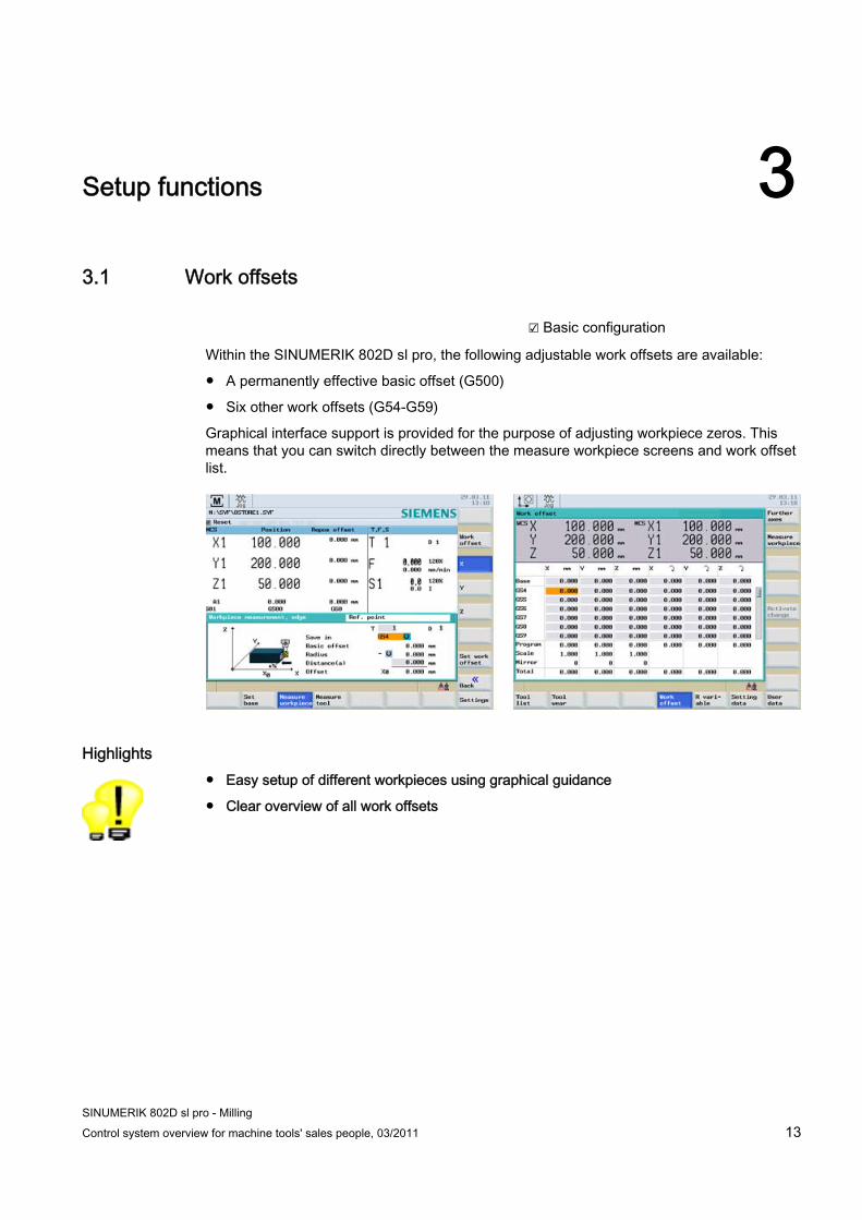
Within the SINUMERIK 802D sl pro, the following adjustable work offsets are available:
● A permanently effective basic offset (G500)
● Six other work offsets (G54-G59)
Graphical interface support is provided for the purpose of adjusting workpiece zeros. This means that you can switch directly between the measure workpiece screens and work offset list.
Highlights ● Easy setup of different workpieces using graphical guidance
● Clear overview of all work offsets

Setup functions 3.2 Measure tools
SINUMERIK 802D sl pro - Milling 14 Control system overview for machine tools' sales people, 03/2011
3.2 Measure tools
3.2.1 Measure tools manually in JOG ☑ Basic configuration
The tool compensation values can be directly determined during machine setup. To this end, the SINUMERIK 802D sl pro offers graphical support for measuring tool length and diameter:
● Enter the dimensions by scratching the edge of the workpiece with the tool. The tool offset data is automatically calculated using the position of the tool-carrier reference point and the position of the workpiece edge; the data is then stored in the tool list.
● Tool diameter can be measured in X-axis or Y-axis direction.
● If required, the measurements of a spacer block can be entered directly (X0 Y0 and Z0).
Highlight ● Save time during tool setup by seeing exactly what you are doing.

Setup functions 3.2 Measure tools
SINUMERIK 802D sl pro - Milling Control system overview for machine tools' sales people, 03/2011 15
3.2.2 Measure tools automatically in JOG ☑ Basic configuration
In JOG mode, you can automatically determine the tool compensation values for the length and diameter in the machine. To this end, the SINUMERIK 802D sl pro offers graphical support for automatic measuring and for calibrating the tool probe.
● To measure the tool diameter and length, simply move the tool near the probe.
● Click "Start". When the probe detects the tool, the controller automatically calculates the tool geometry.
Highlight ● Speedy and precise tool measuring is standard
● Pre-installed graphic support for measuring with tool probe

Setup functions 3.3 Tool data management
SINUMERIK 802D sl pro - Milling 16 Control system overview for machine tools' sales people, 03/2011
3.3 Tool data management
3.3.1 Tool list ☑ Basic configuration
For the purpose of managing tools, the SINUMERIK 802D sl pro provides you with an easy-to-use tool list, which displays all relevant tool data and wear.
● In the tool list, you can create and delete tools using softkeys.
● For each tool, you can store the following data:
– Special symbol for the individual tool type with direction of tool orientation (miller or drill)
– Tools are displayed in the list with a number, e.g. T1.
– Number of the offset set for the tool cutting edge, e.g. D1
– Tool offset data in the form of length and radius
– Values for geometry and wear in a single table
● Using individual password protection, you can specify the maximum permissible input values for tool wear to avoid collisions, for example. This can be done using display machine data MD 208, MD 209 and MD 374.
Highlight ● All tool data at a glance
● Higher degree of reliability when managing tool data
Setup functions 3.3 Tool data management
SINUMERIK 802D sl pro - Milling Control system overview for machine tools' sales people, 03/2011 17
3.3.2 Monitoring of tool life and quantity of workpieces ☑ Basic configuration
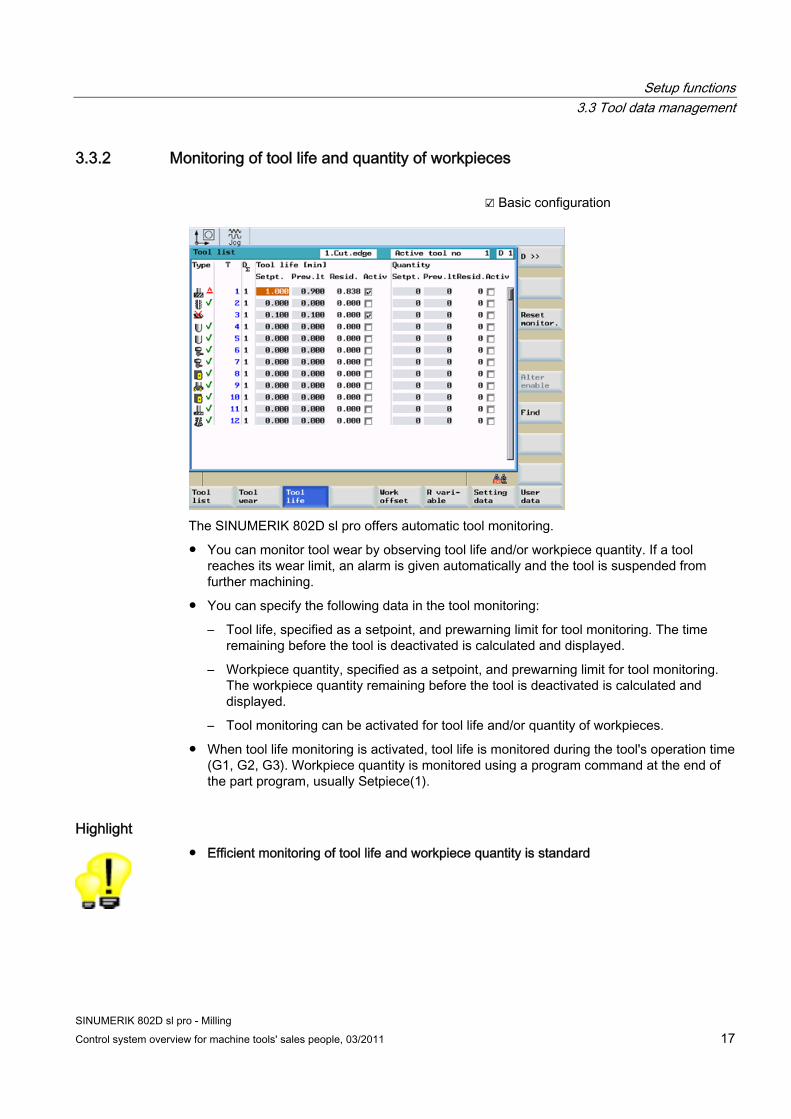
The SINUMERIK 802D sl pro offers automatic tool monitoring.
● You can monitor tool wear by observing tool life and/or workpiece quantity. If a tool reaches its wear limit, an alarm is given automatically and the tool is suspended from further machining.
● You can specify the following data in the tool monitoring:
– Tool life, specified as a setpoint, and prewarning limit for tool monitoring. The time remaining before the tool is deactivated is calculated and displayed.
– Workpiece quantity, specified as a setpoint, and prewarning limit for tool monitoring. The workpiece quantity remaining before the tool is deactivated is calculated and displayed.
– Tool monitoring can be activated for tool life and/or quantity of workpieces.
● When tool life monitoring is activated, tool life is monitored during the tool's operation time (G1, G2, G3). Workpiece quantity is monitored using a program command at the end of the part program, usually Setpiece(1).
Highlight ● Efficient monitoring of tool life and workpiece quantity is standard
Setup functions 3.4 Face milling in MDI mode
SINUMERIK 802D sl pro - Milling 18 Control system overview for machine tools' sales people, 03/2011
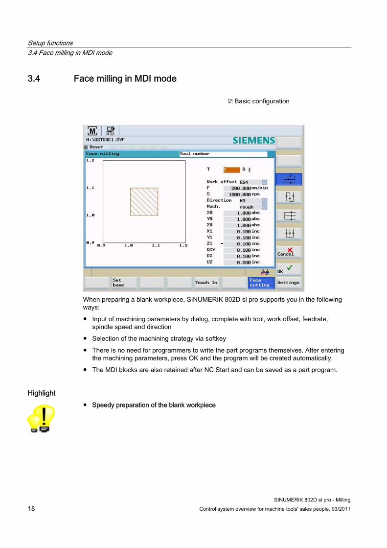
3.4 Face milling in MDI mode ☑ Basic configuration
When preparing a blank workpiece, SINUMERIK 802D sl pro supports you in the following ways:
● Input of machining parameters by dialog, complete with tool, work offset, feedrate, spindle speed and direction
● Selection of the machining strategy via softkey
● There is no need for programmers to write the part programs themselves. After entering the machining parameters, press OK and the program will be created automatically.
● The MDI blocks are also retained after NC Start and can be saved as a part program.
Highlight ● Speedy preparation of the blank workpiece

SINUMERIK 802D sl pro - Milling Control system overview for machine tools' sales people, 03/2011 19
Program management and user memory 44.1 Program Manager
☑ Basic configuration
Using the SINUMERIK 802D sl pro Program Manager, you can easily manage your part programs.
● PC-like functions, e.g. Mark, Copy, Paste, and Rename
● File names for part programs can be entered in clear text, making them easy to identify (max. 25 characters).
● Clear structures with subdirectories on several levels
● Quick search function based on entry of the 1st letter of the program name. The controller automatically positions the cursor on a program with the initial letter matching that which was entered.
● Preview of the first seven lines of the part program before editing
● All part programs available on the machine, thanks to the 3 MB user memory
● Access to shared network drives and sharing of directories for remote access via Ethernet networking
Highlights ● Better overview with clear-text file names
● User-friendly data handling in typical PC style with copy, paste, rename, etc.

Program management and user memory 4.2 User memory and data management
SINUMERIK 802D sl pro - Milling 20 Control system overview for machine tools' sales people, 03/2011
4.2 User memory and data management
4.2.1 Buffered CNC user memory ☑ Basic configuration
SINUMERIK 802D sl pro 3 MB
Management of up to 100 part programs. For larger quantities, we recommend that part programs be managed using the CF card.
Highlight ● Large memory space included in scope of delivery
4.2.2 Compact Flash card ☑ Basic configuration, only CompactFlash card required
A CompactFlash card slot is located directly at the operator panel front of the SINUMERIK 802D sl. • Card can be inserted or removed during operation, i.e., the
machine does not have to be restarted in order for the CompactFlash card to be recognized.
• Cover can be closed while the card is inserted in order to protect the unit from dust.
• Load and execute part programs from the CompactFlash card• No loss in speed during execution of part programs from the
CompactFlash card (DNC operation) • No special software necessary for reading/writing
CompactFlash cards via PC
Part programs on the CompactFlash card are not edited on the control, but instead, at the PC.
Highlight ● Powerful and reliable solution for handling a large volume of user data

Program management and user memory 4.2 User memory and data management
SINUMERIK 802D sl pro - Milling Control system overview for machine tools' sales people, 03/2011 21
4.2.3 Slot for USB stick ☑ Basic configuration, only USB stick required
In the SINUMERIK 802D sl, a slot is reserved for a USB stick. • USB stick can be inserted or removed
during operation, i.e., the machine does not have to be restarted in order for the USB stick to be recognized.
• Load and execute part programs from the USB stick
• No loss in speed during execution of part programs from the USB stick (DNC operation)
• No special software necessary for reading/writing the USB stick via PC
Part programs on the USB stick are not edited via controller, but rather via PC.
Highlight ● Powerful and reliable solution for handling a large volume of user data
● Freedom in the selection of the mass storage device

Program management and user memory 4.2 User memory and data management
SINUMERIK 802D sl pro - Milling 22 Control system overview for machine tools' sales people, 03/2011
4.2.4 Serial data transfer ☑ Basic configuration, installation of
RCS802 tool on PC (included on Toolbox CD as standard)
The SINUMERIK 802D sl pro facilitates easy data transfer to an from PCs via the RS 232 interface. To do this, install the RCS802 tool on your PC. • Backing up of machine data • Archive/series startup file • Backing up of part program data
Note: If you have not received the Toolbox CD, please contact your machine OEM.
Highlight ● Easy and well proven data transfer
4.2.5 Ethernet networking ☑ Basic configuration
The SINUMERIK 802D sl pro is set up for Ethernet (TCP/IP) networking (RJ45 connection). • The data transfer rate is 10/100 Mbps. • Remote access to the controller via the RCS802 tool, e.g.
for setup and remote diagnostics (PC license required) • Access to the network drives is available directly from the
program manager. No additional software is required on the server.
Highlight ● Easy and economical connection via Ethernet (TCP/IP) to Windows PCs or Unix
workstations

SINUMERIK 802D sl pro - Milling Control system overview for machine tools' sales people, 03/2011 23
Programming 55.1 DIN/ISO language
☑ Basic configuration
For DIN/ISO programming purposes, the SINUMERIK 802D sl pro offers a large pool of commands which are oriented towards the task at hand:
● G-code according to DIN66025 and in ISO dialect mode
● G-functions and extended G-functions
Powerful commands, e.g. CIP for circular interpolation via intermediate point
● Unlimited number of programmable work offsets
Using the commands TRANS, SCALE, MIRROR, ROT, you can shift, scale, mirror, and rotate the workpiece coordinate system as required.
● Calculation operations and logic operations of variables
These calculation operations include, e.g.: +, -, *, /, sin, cos, exp, ==, <>
● User data
You can freely define variables in the part program using names (clear text) and type (LUDs, no GUDs).
● R parameters (calculation parameters)
300 predefined R parameters are available as flexible calculation variables (floating point format).
● System variables
Access from the program to, for example, tool offsets, axis positions and measuring values
● Program control structures
Language commands such as IF and GOTO are available for programming with conditions and loops.
Highlight ● Unbeatable pool of commands for flexible and time-optimized part programs
Programming 5.2 DIN/ISO editor
SINUMERIK 802D sl pro - Milling 24 Control system overview for machine tools' sales people, 03/2011
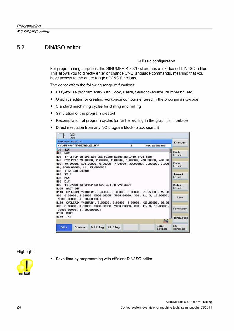
5.2 DIN/ISO editor ☑ Basic configuration
For programming purposes, the SINUMERIK 802D sl pro has a text-based DIN/ISO editor. This allows you to directly enter or change CNC language commands, meaning that you have access to the entire range of CNC functions.
The editor offers the following range of functions:
● Easy-to-use program entry with Copy, Paste, Search/Replace, Numbering, etc.
● Graphics editor for creating workpiece contours entered in the program as G-code
● Standard machining cycles for drilling and milling
● Simulation of the program created
● Recompilation of program cycles for further editing in the graphical interface
● Direct execution from any NC program block (block search)
Highlight ● Save time by programming with efficient DIN/ISO editor

Programming 5.3 Machining Cycles
SINUMERIK 802D sl pro - Milling Control system overview for machine tools' sales people, 03/2011 25
5.3 Machining Cycles ☑ Basic configuration
In the case of recurring machining operations, the SINUMERIK 802D sl pro provides you with graphical support for the following technology canned cycles. You can parameterize these and assemble them for the program in any way you wish. • Milling
– Face milling – Contour milling – Rectangular pocket and spigot, circular
pocket and spigot – Elongated holes on a circle, slots on a
circle, circumferential slots – Thread milling (inside and outside)
• Drilling – Centering, drilling, counter-boring,
reaming, deep-hole drilling, tapping – Repetition of hole machining using hole
patterns row/circle (MCALL)
Comprehensive functional and graphical support is provided: • During parameterization, support is
provided by the clear pictures and infotexts accompanying the parameters, e.g. finishing allowance in depth.
• A comprehensive range of choices is available for effective machining, such as helical insertion for rectangular and circular pockets.
• Thread milling, including helical interpolation of all three geometry axes X, Y and Z, is contained within the basic configuration.
Highlight ● Graphical cycle support helps you create your part program faster
● Highly flexible G-code programming extended by graphical cycles
Programming 5.4 On-board user manual
SINUMERIK 802D sl pro - Milling 26 Control system overview for machine tools' sales people, 03/2011
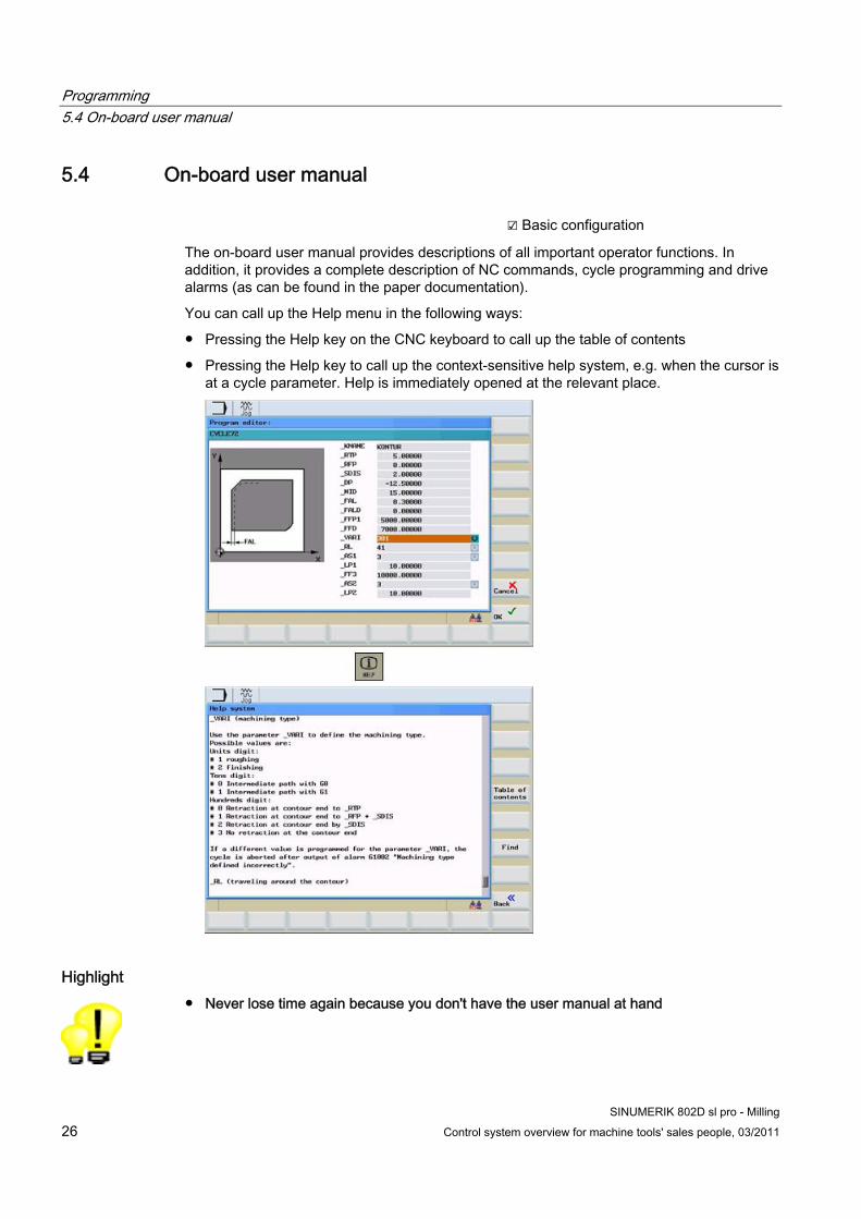
5.4 On-board user manual ☑ Basic configuration
The on-board user manual provides descriptions of all important operator functions. In addition, it provides a complete description of NC commands, cycle programming and drive alarms (as can be found in the paper documentation).
You can call up the Help menu in the following ways:
● Pressing the Help key on the CNC keyboard to call up the table of contents
● Pressing the Help key to call up the context-sensitive help system, e.g. when the cursor is at a cycle parameter. Help is immediately opened at the relevant place.
Highlight ● Never lose time again because you don't have the user manual at hand

Programming 5.5 On-board pocket calculator
SINUMERIK 802D sl pro - Milling Control system overview for machine tools' sales people, 03/2011 27
5.5 On-board pocket calculator ☑ Basic configuration
The integrated pocket calculator offers the following range of functions:
● Callable from any operating area
● Take over a value from an input field and write it back after calculation
● Four basic calculation operations, as well as sine, cosine, square, and square root functions
● Bracket function for calculating nested terms
● Functions for calculating construction points on a contour, e.g.:
– Tangential transition between a circle sector and a straight line
– Converting polar coordinates to Cartesian coordinates
● By pressing the input key, you can see the result of a calculation before you confirm it with the accept softkey.
Highlight ● More certainty for operating and programming thanks to integrated pocket calculator - no
more calculation or typing mistakes

Programming 5.6 Free Contour Programming / Contour Calculator
SINUMERIK 802D sl pro - Milling 28 Control system overview for machine tools' sales people, 03/2011
5.6 Free Contour Programming / Contour Calculator ☑ Basic configuration
The SINUMERIK 802D sl supports you in free programming, from simple to complex contours. Free contour programming is a support tool for the DIN/ISO editor. Programs can be decompiled in the program editor and can thus be revised in the contour calculator.
You can include the following contour elements and parameterize them in screen forms:
● Straight line in the X direction
● Straight line in the Y direction
● Oblique line in the X/Y direction. You can enter the end point of the straight line using coordinates or an angle.
● Arc with any direction of rotation.
Additional screen forms enable you to determine the starting point and to close the contour.
The contour calculator supports you in programming the following functions, among others: • Calculation of only partly determined
elements, as soon as the missing parameters can be derived from parameters already known, e.g. geometrical data missing in the parts drawing.
• Chaining of contour elements. • Insert radius or chamfer between two
contour elements. • Transfer of the programmed contours to
the edited part program. • It is possible to delete and insert contour
elements at a later stage

Programming 5.6 Free Contour Programming / Contour Calculator
SINUMERIK 802D sl pro - Milling Control system overview for machine tools' sales people, 03/2011 29
The following functions make it easier to work with the contour calculator:
When you select this softkey, you can use the cursor keys to determine a picture detail that is to be enlarged.
After selection of this softkey, graphical help screens will be displayed in addition to the relevant parameters.
Highlight ● Quickly and reliably from the drawing to the finished workpiece
● Program decompilation for further processing in the contour calculator
● Easy input of the workpiece geometry: "Drawing dot for dot" like in ShopMill
Programming 5.6 Free Contour Programming / Contour Calculator
SINUMERIK 802D sl pro - Milling 30 Control system overview for machine tools' sales people, 03/2011
SINUMERIK 802D sl pro - Milling Control system overview for machine tools' sales people, 03/2011 31
Simulation 6
☑ Basic configuration
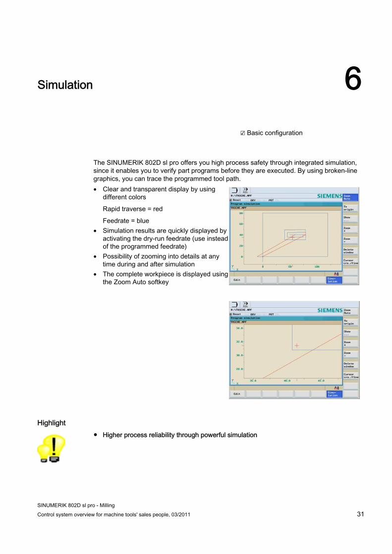
The SINUMERIK 802D sl pro offers you high process safety through integrated simulation, since it enables you to verify part programs before they are executed. By using broken-line graphics, you can trace the programmed tool path. • Clear and transparent display by using
different colors
Rapid traverse = red
Feedrate = blue • Simulation results are quickly displayed by
activating the dry-run feedrate (use instead of the programmed feedrate)
• Possibility of zooming into details at any time during and after simulation
• The complete workpiece is displayed using the Zoom Auto softkey
Highlight ● Higher process reliability through powerful simulation

Simulation
SINUMERIK 802D sl pro - Milling 32 Control system overview for machine tools' sales people, 03/2011
SINUMERIK 802D sl pro - Milling Control system overview for machine tools' sales people, 03/2011 33
4th axis machining and mold and die 77.1 4th axis machining
7.1.1 Overview The SINUMERIK 802D sl pro provides you with a comprehensive range of functions for machining centers with a rotary table or dividing unit. This includes:
● Clamping several workpieces to a dividing unit / turning clamp
● Clamping a workpiece to a rotary table
● 4-axis part programs from CAD-CAM systems
Highlight ● Machining of complex workpieces with standard package possible
7.1.2 Machining on workpiece periphery (TRACYL) ☑ Basic configuration
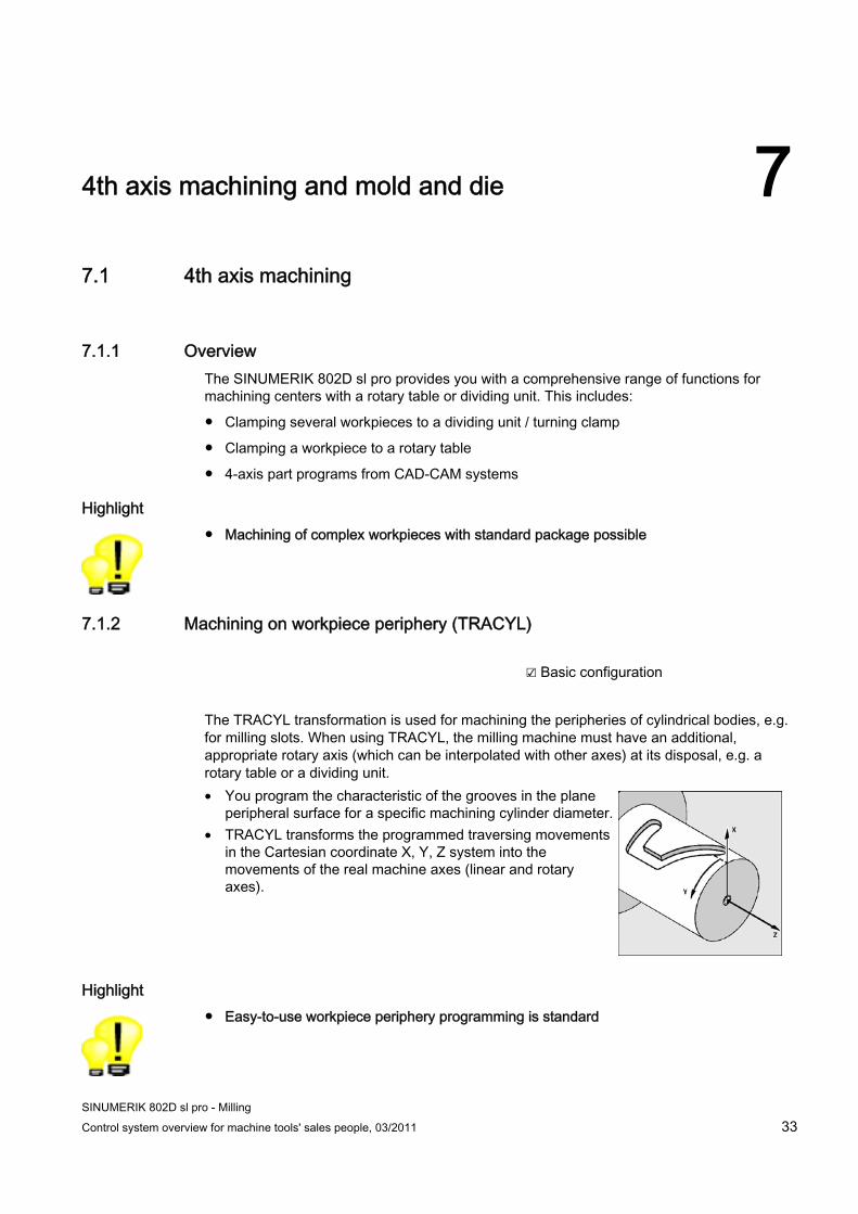
The TRACYL transformation is used for machining the peripheries of cylindrical bodies, e.g. for milling slots. When using TRACYL, the milling machine must have an additional, appropriate rotary axis (which can be interpolated with other axes) at its disposal, e.g. a rotary table or a dividing unit. • You program the characteristic of the grooves in the plane
peripheral surface for a specific machining cylinder diameter. • TRACYL transforms the programmed traversing movements
in the Cartesian coordinate X, Y, Z system into the movements of the real machine axes (linear and rotary axes).
Highlight ● Easy-to-use workpiece periphery programming is standard

4th axis machining and mold and die 7.2 3-axis mold and die machining
SINUMERIK 802D sl pro - Milling 34 Control system overview for machine tools' sales people, 03/2011
7.1.3 4-axis interpolation ☑ Basic configuration
The SINUMERIK 802D sl pro supports 4th axis machining, e.g. for rotary tables and swiveling tables.
Using the program command FGROUP, all 4 axes can be interpolated, e.g. FGROUP (X, Y, Z, A).
Highlight ● 4-axis interpolation is standard
7.2 3-axis mold and die machining
7.2.1 Overview The SINUMERIK 802D sl pro provides the best conditions for mold-making applications: The advanced technology of the SINUMERIK 840D is also available in the SINUMERIK 802D sl pro, e.g.: • Jerk limitations separated by rapid traverse
/ feed • Following error compensation (feedforward
control) • 100 blocks Look Ahead • Online compressor • Large mold-making programs can be
transferred and directly executed via CompactFlash card, USB stick or Ethernet.
Highlight ● Machining of mold-making workpieces is already standard
4th axis machining and mold and die 7.2 3-axis mold and die machining
SINUMERIK 802D sl pro - Milling Control system overview for machine tools' sales people, 03/2011 35
7.2.2 Online compressor ☑ Basic configuration
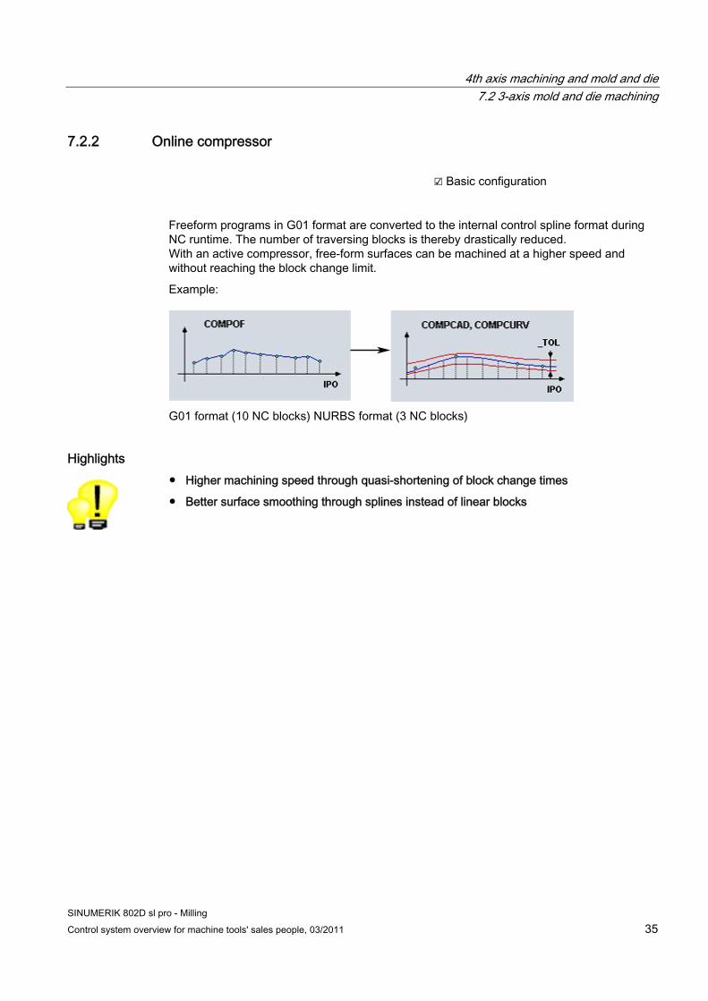
Freeform programs in G01 format are converted to the internal control spline format during NC runtime. The number of traversing blocks is thereby drastically reduced. With an active compressor, free-form surfaces can be machined at a higher speed and without reaching the block change limit.
Example:
G01 format (10 NC blocks) NURBS format (3 NC blocks)
Highlights ● Higher machining speed through quasi-shortening of block change times
● Better surface smoothing through splines instead of linear blocks

4th axis machining and mold and die 7.2 3-axis mold and die machining
SINUMERIK 802D sl pro - Milling 36 Control system overview for machine tools' sales people, 03/2011
7.2.3 Jerk limitation ☑ Basic configuration
The control calculates a steady acceleration profile instead of jumps in acceleration. This enables jerk-free velocity characteristics for the involved path axes. The jerk limitation can also be directly activated in the part program with the »SOFT« NC language command.
t
with jerk limitation Without jerk limitation
Path
vel
oci
ty
Highlights ● Longer machine lifespan through protection of the mechanical components
● Higher path accuracy through softer acceleration
4th axis machining and mold and die 7.2 3-axis mold and die machining
SINUMERIK 802D sl pro - Milling Control system overview for machine tools' sales people, 03/2011 37
7.2.4 Dynamic feedforward control ☑ Basic configuration
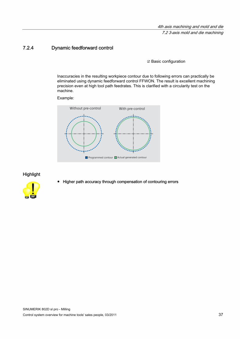
Inaccuracies in the resulting workpiece contour due to following errors can practically be eliminated using dynamic feedforward control FFWON. The result is excellent machining precision even at high tool path feedrates. This is clarified with a circularity test on the machine.
Example:
With pre-controlWithout pre-control
Actual generated contourProgrammed contour
Highlight ● Higher path accuracy through compensation of contouring errors

4th axis machining and mold and die 7.2 3-axis mold and die machining
SINUMERIK 802D sl pro - Milling 38 Control system overview for machine tools' sales people, 03/2011
7.2.5 Look Ahead ☑ Basic configuration
The »Look Ahead« function is a means of optimizing the machining speed by »looking ahead« over a parameterizable number of traversing blocks. With tangential block transitions, the axis is accelerated and decelerated beyond block boundaries, so that no drops in velocity occur.
The SINUMERIK 802D sl pro allows up to 100 blocks Look Ahead.
G64
t
Path
vel
oci
ty
N2 N4N3N1 N5 N6
F programmedG64 with Look Ahead
G64 without Look Ahead
Highlight ● Shorter machining times through optimum velocity control
7.2.6 Block search ☑ Basic configuration
A block search may be executed in machine status RESET, e.g. after a program interruption or to specifically return to machining The program data are prepared in such a way that all relevant parameters (tool, work offsets, etc.) are available upon continuation of the program.
The following search variants are available:
● To the interruption point
● To any CNC block in the DIN/ISO programs
● To any subroutine levels in DIN/ISO programs
Highlights ● Time-saving and secure re-start at any program point, as no editing of the part program is
required
SINUMERIK 802D sl pro - Milling Control system overview for machine tools' sales people, 03/2011 39
Multilingual operator interface 8
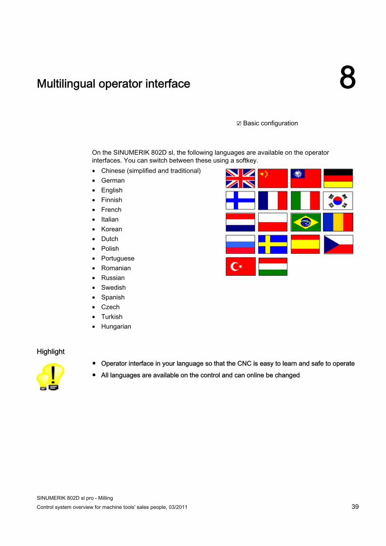
☑ Basic configuration
On the SINUMERIK 802D sl, the following languages are available on the operator interfaces. You can switch between these using a softkey. • Chinese (simplified and traditional) • German • English • Finnish • French • Italian • Korean • Dutch • Polish • Portuguese • Romanian • Russian • Swedish • Spanish • Czech • Turkish • Hungarian
Highlight ● Operator interface in your language so that the CNC is easy to learn and safe to operate
● All languages are available on the control and can online be changed

Multilingual operator interface
SINUMERIK 802D sl pro - Milling 40 Control system overview for machine tools' sales people, 03/2011

SINUMERIK 802D sl pro - Milling Control system overview for machine tools' sales people, 03/2011 41
Maintenance and diagnostics 99.1 Maintenance-free operation
☑ Basic configuration
The SINUMERIK 802D sl offers maintenance-free operation:
● High reliability, because the SINUMERIK 802D sl has no hard disk, no battery and no fan
● Complete data backup on CF card, with all drive data
Highlight ● Highest machine availability thanks to reliable hardware

Maintenance and diagnostics 9.2 Diagnostics
SINUMERIK 802D sl pro - Milling 42 Control system overview for machine tools' sales people, 03/2011
9.2 Diagnostics ☑ Basic configuration
The SINUMERIK 802D sl offers diagnostic functions which are easy to use:
● Diagnostic functions, such as ladder display, are available for finding causes of malfunctions or a PLC program error.
● You can switch between two windows in ladder display (e.g. for cross-references).
● You are provided with the same display as on a PC, with zoom, find, symbol info, and cross-reference functions.
● For reasons of safety, it is not possible to edit the PLC program at the machine.
Highlight ● Highest machine availability thanks to modern diagnostic and troubleshooting tools

Maintenance and diagnostics 9.3 Remote diagnostics
SINUMERIK 802D sl pro - Milling Control system overview for machine tools' sales people, 03/2011 43
9.3 Remote diagnostics ☑ RCS802 on CD-ROM, included in scope of delivery
☑ Option: RCS802 remote diagnostics via Ethernet (PC license)
With the RCS802 software for PC, you can carry out remote diagnostics via the serial interface.
● With the SINUMERIK 802D sl pro, remote diagnostics can also be carried out via Ethernet (PC license).
● When connecting the PC to several machines, only one PC license is necessary for remote diagnostics via Ethernet.
● All machine tool controller diagnostic functions are also available in remote diagnostics.
Highlight ● Shorter reaction times and lower service costs thanks to remote diagnostics

Maintenance and diagnostics 9.3 Remote diagnostics
SINUMERIK 802D sl pro - Milling 44 Control system overview for machine tools' sales people, 03/2011

SINUMERIK 802D sl pro - Milling Control system overview for machine tools' sales people, 03/2011 45
Ordering data 10
The main information required for ordering is listed below:
SINUMERIK 802D sl Version T/M pro 6FC5370-0AA00-3AA1 Toolbox CD-ROM -> Already included with each 802D sl: including additional language files for operator interface, RCS 802 software and PLC library
6FC5810-0YC00-0YA8
License disk for enabling a PC for • Remote control • Snap shots via Ethernet
6FC6000-6DA51-0AA0

Ordering data
SINUMERIK 802D sl pro - Milling 46 Control system overview for machine tools' sales people, 03/2011
SINUMERIK 802D sl pro - Milling Control system overview for machine tools' sales people, 03/2011 47
Summary of unique selling points 11
The SINUMERIK 802D sl operator panel control has the following outstanding features, which sets itself apart from the competition:
User-friendly operation • Graphical support for setting up tools and
workpiece zeros • CompactFlash card, USB stick and Ethernet for
unlimited user memory • Graphical program simulation with zoom
Time-saving programming • Flexible G-code programming • Graphical support for technological machining
cycles and contour editor • Completely integrated user manual
Increased productivity • 4th axis machining and mold-making • Maintenance free operation and user-friendly
diagnostics • Programming and training software for the PC

Summary of unique selling points
SINUMERIK 802D sl pro - Milling 48 Control system overview for machine tools' sales people, 03/2011

SINUMERIK 802D sl pro - Milling Control system overview for machine tools' sales people, 03/2011 49
Index
B Block search, 38
C CNC keyboard, 10 CNC memory, 20 CompactFlash card, 20 Compressor, 35 Contour calculator, 28 Contour programming, 28 Cycles, 25
E Ethernet, 22
F Feedforward control, 37 Field of application, 7 Flash card, 20
L Look Ahead, 38
M Machine spectrum, 7 Mold-making, 33
N Networking, 22
O Operator panel front, 10 Ordering data, 45
P Pocket calculator, 27 Program manager, 19
S Serial data transfer, 22 SINUMERIK 802D sl, 9
T TCP/IP, 22 Tool list, 16
U Unique selling points, 47 USB stick, 21 User memory, 20
V Velocity control, 36
W Work offsets, 13

Index
SINUMERIK 802D sl pro - Milling 50 Control system overview for machine tools' sales people, 03/2011