single particle fragmentation in ultrasound assisted ... particle fragmentation in ultrasound...
TRANSCRIPT

Single Particle Fragmentation in Ultrasound
Assisted Impact Comminution
Falk K. Wittel a
aComputational Physics for Engineering Materials, Institute for BuildingMaterials (IFB), ETH Zurich, Schafmattstrasse 6, HIF; CH-8093 Zurich
Abstract
Impact fragmentation is the underlying principle of comminution milling of dry,bulk solids. Unfortunately the outcome of the fragmentation process is more or lessdetermined by the dimensionality of the impactor and its impact velocity. Since frag-mentation is dominated by interfering shock waves, manipulating traveling shockwaves and adding energy to the system during its fragmentation could be a promis-ing approach to manipulate fragment mass distributions and energy input. In aformer study we explored mechanisms in impact fragmentation of spheres, usinga three-dimensional Discrete Element Model (DEM)[1]. This work is focused onstudying how single spheres fragment when impacted on a planar vibrating target.
Key words: mpact comminution, fragmentation, DEM, ultra sonic
1 Introduction
Fragmentation is the fundamental underlying process in many industrial com-minution applications. Size reduction to desired fragment mass distributionsare wanted, minimizing the energy input and process times. Single particlecomminution is one of the most efficient size reduction methods, since theenormous energy losses in other processes, such as ball milling, originate fromfrictional inter-particle collisions [2]. Therefore the focus of studies is on un-derstanding and optimizing single particle comminution, most of the time byconsidering circular and spherical impactors. Experiments range from singleor double impact of large concrete [3, 4] or plaster [5, 6] balls over ceramic[7–9] or glass [5, 10–12] spheres in the millimeter range. Spheres of photo
∗ Corresponding author. Tel.:+41-44-633-2871Email address: [email protected] (Falk K. Wittel).
Preprint submitted to Elsevier 19 March 2018
arX
iv:1
509.
0270
5v1
[co
nd-m
at.m
trl-
sci]
9 S
ep 2
015

elastic active polymers like PMMA allowed a partial insight into the stressfield dynamics during the fragmentation process [13, 14] and the crack for-mation inside the impactor, straightening the fact, that the problem can bydescribed correctly only by fully tree dimensional (3D) models. Due to theviolent dynamic nature of fragmentation, including multiple contacts, mostlymolecular dynamics or discrete element methods (DEM) were used. However3D simulations are rare and mainly 2D simulations, that can only describedisc fragmentation, were performed [3, 15–20]. Potapov and Campbell [21, 22]introduced a 3D fragmentation simulation of spheres, composed of polyhe-dral particles, resulting in small system sizes, that allowed only for a roughestimate of the experimentally observed fragmentation mechanism. By usingspherical particles, Thornton et.al. [23, 24] could increase the particle numberup to 5000, however the cohesive interactions remained quite simple. In a pre-vious work we studied in detail the dynamics of fragmentation mechanismsduring single particle impact of a system composed of an agglomeration ofapproximately 22000 spherical particles, interconnected by 3D beam elements[1] and demonstrated the agreement with experiments.
When it comes to the technological realization via impact comminution milling,attempts to manipulate the outcome of the fragmentation process focus onprocess parameter like impact velocity, impact angle [15], target stiffness andshape [3]. Fragmentation of disordered, brittle materials however proved to bea quite universal phenomenon that is mainly concerned with the impact veloc-ity and way shock waves propagate inside the system. Experiments [25, 26], aswell as simulations [27–31] repeatedly showed, that the outcome of the frag-mentation in terms of the fragment mass and size distribution, follows a powerlaw in the range of small fragments with exponents, that are universal withrespect to the specific material or the way energy is imparted in the system.
An explanation for the universality in fragmentation and its dimensional de-pendency is the similarity of propagating shock waves for various materialsand impactor geometries, leading to identical fragmentation mechanisms. Away to manipulate the outcome of fragmentation could be the manipulationof the shock wave configurations. The available energy for the formation ofnew surfaces in single particle impact is fixed by the kinetic energy of the im-pactor. This paper proposes the modification of shock front configurations. Inmedicine, destruction of kidney stones via extracorporeal shock wave lithotrip-syhas has become a standard medical procedure. However for excitation, oneeither needs a good acoustic coupling, e.g. via fluids or a lot of time. Bothis not possible in impact fragmentation, however one can excite the impactordirectly at the impact, by vibrating the target. This ultrasonic assisted frag-mentation is simulated using our previous model [1] only with a larger numberof particles and a target that is vibrating with adjustable amplitudes and fre-quencies. First the utilized model is recalled, before internal stress fields, en-ergetics, damage evolution, fragmentation mechanisms, and the final outcome
2
at various settings are compared.
2 Model and system construction
Since the DEM was proposed by Cundall and Struck in 1979 [32], the approachhad a strong attraction for the simulation of rock mechanics and brittle failurein particular. The reasons are obvious, when thinking of brittle, heterogeneousand disordered materials, that are full of defects by nature. When the ultimatestrength is reached, the solid fails through the propagation of cracks, whosespeed is controlled by the available energy, its flux to the failure zones and in-stabilities at the small scales. By representing the material via a discontinuousparticle agglomeration and solving the dynamic linear and non-linear interac-tion of all particles, one obtains a system with complex behavior on the modelscale and in particular in the crack process zones. From this, many macroscop-ically observed fracture phenomena naturally emerge, like size effects or cracktip instabilities with resulting crack branching and merging in dynamic propa-gation. Today DEM is defined as a collection of numerical methods that allowfor finite displacements and rotations of discrete bodies including complete de-tachment [33]. It is basically an explicit solution of a many body system withneighborhood search and special interaction potentials from arbitrary con-tact and rheological cohesive elements. Being a dynamic simulation schemewith bottom up description of the material with inherent disorder, crackingproperties and crack-crack interactions naturally emerge.
a bi
i
j
j
j
,b
,b
,bQ
Q
Qi
i
,b
,b
M
M
j
,bM
ii j
j
ij
ij
r
RR
x
,bM
j
i,bQ
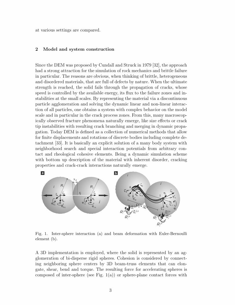
Fig. 1. Inter-sphere interaction (a) and beam deformation with Euler-Bernoullielement (b).
A 3D implementation is employed, where the solid is represented by an ag-glomeration of bi-disperse rigid spheres. Cohesion is considered by connect-ing neighboring sphere centers by 3D beam-truss elements that can elon-gate, shear, bend and torque. The resulting force for accelerating spheres iscomposed of inter-sphere (see Fig. 1(a)) or sphere-plane contact forces with
3

Hertzian contact, axial forces from the truss, bending forces and momentstransmitted by intact beams (see Fig. 1(b)) and volumetric forces. Beam ele-ments are allowed to fail to explicitly model damage and fracture of the solid.The utilized failure criterion on the element level considers failure due to acombination of straining and bending by comparing actual states to thresh-old values originating from a Weibull distribution. The material disorder istherefore considered by the physical disorder in element breaking thresholdsand topological disorder of elements. While the first one determines how thesystem reacts on a crack tip, namely the failure behavior, the second one isessential for obtaining realistic crack morphologies and isotropic wave propa-gation. Additionally damping, friction forces and torque of cohesive elementsare implemented. A detailed description of the model, its calibration and ver-ification can be found in Ref. [1].
The system construction is a crucial step in fragmentation simulations to avoidartifacts arising from the discretization, that are difficult to detect. Namelyanisotropic properties, nonuniform wave propagation or preferred crack ori-entations due to particle clustering or larger zones with crystalline particlearrangement have to be avoided. By using particles of slightly different sizeswith diameter d2 = 0.95d1 of equal portions, crystalline zones can be avoided.The generation of a random agglomeration starts with an initial configurationof particles placed on a regular cubic lattice and assign random initial veloci-ties to the particles that can move and collide in a simulation box with periodicboundaries. After this randomization step, a small central gravitational field inthe center of the simulation box is activated to build one big, nearly sphericalcluster of randomized spheres. After the kinetic energy has been dissipated bydamping, the set of vertices is triangulated and beam elements are assignedto all edges using a Delaunay triangulation [34]. By calculating the angularcorrelation of neighboring elements we could verify that crystallization is notsignificant, and radial alignment is not detectable [1]. When the connectivityof the future beam network is found, the gravitational field is slowly removed,while the elastic beam properties are simultaneously increased. The result-ing expansion reduces the contact forces. By reinitializing the beam lengthsand orientations, residual stresses can be removed. The system constructionis completed by trimming it to the desired shape by element removal.
Finally the system is placed at a small distance from a frictionless target platewith a 20 times higher stiffness than the spheres. The vibration of the targetis considered by periodically displacing the target plate with wave length wtand amplitude at. The time evolution of the system is followed using a 6th
order Gear predictor-corrector scheme with quaternion angle representations.Since the time increment ∆t is around 3 ns, high frequencies can be resolvedquite well. For a comparison, the contact time between impactor and targetis around 30 µs.
4

3 Energetics and Stress Distribution
When monitoring the total energy of the system during impact, energy dissi-pation due to damage formation, friction and damping is observed. For sta-tionary targets the total energy will always be less or equal the initial kineticenergy. However for vibrating targets, energy is transmitted to the impactorif the wave length w gets smaller than the contact time ∆tc (see Fig. 2(a)).Note that the contact time for the system at an impact speed of 145 m/s isabout 31 µs and the time for wave transmission of compression waves fromthe bottom to the top is about 7 µs. Therefore the number of wave packagesthat can be transmitted to the system is limited by the contact time.
To obtain an insight into the stress fields just before the system disintegrationand the ideal increase in energy, an explicit Finite Element (FE) analysis usingABAQUS is employed. The FE model consists of quadratic axisymmetric 8-node elements, who’s assigned properties originate from measurements on theDEM sample. Contact times, shock wave velocity and elastic energy showexcellent agreement with the DEM simulation [1]. Note that the impactordiameter is 16mm, Young’s modulus is E=7.4GPa, density is ρ =1920kg/m3,Poissonian number ν=0.2, resulting in a longitudinal wave speed of ≈ 2200±100m/s, parameters that are in the range of lean concrete mixtures. Contactis defined as frictionless in tangential direction and hard in normal direction.
The energy of the sphere before and after impact can be compared using theFEM model to obtain a rough estimate of the energy transfer due to the vibra-tion when failure is not present (see Fig. 2(a)). To maximize energy transfer,
b
2 13456710
12
3
4
5
67
8
910
11
12
15
16
wavelength w [ms]t
4 8 126 10 14 16
0.2
0.4
0.8
0.6
1
0
norm
aliz
ed g
enera
lized m
ass
0 5 10 15 20 25 301
2
200mm
150
100
7050
40
10
3
4
5
6
energ
etic
rest
itutio
n c
oeffic
ient
wavelength w [ms]t
a
3020
Fig. 2. Energy increase due to contact stimulation of eigenmodes for amplitudesranging from 10 to 200µm, impact velocity vi = 145m/s and various wave lengths(a). In (b) the generalized mass, normalized by the total system mass is given for thefirst eigenmodes (1-7,10). Note that the generalized mass is defined by the productθNαM
NMθMα of the model’s mass matrix MNM with the α − th eigenvector θNαeigenvector of the model. N and M refer to the degrees of freedom of the model.
simulating eigenmodes is most promising. Looking at the first eigenmodes, it
5
is evident, that only a selection can be excited by displacing the contact zone.However by exaltation with wt ≈ 7 µm, already a large number of modes isstimulated simultaneously (see Fig. 2).
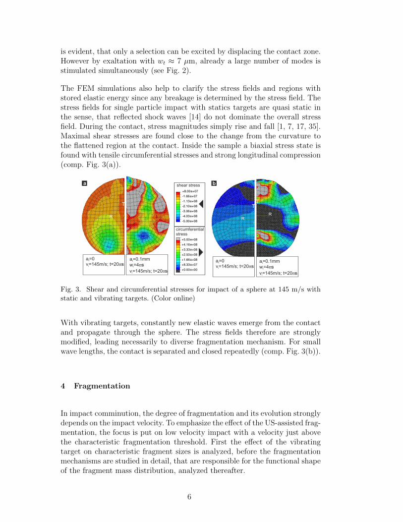
The FEM simulations also help to clarify the stress fields and regions withstored elastic energy since any breakage is determined by the stress field. Thestress fields for single particle impact with statics targets are quasi static inthe sense, that reflected shock waves [14] do not dominate the overall stressfield. During the contact, stress magnitudes simply rise and fall [1, 7, 17, 35].Maximal shear stresses are found close to the change from the curvature tothe flattened region at the contact. Inside the sample a biaxial stress state isfound with tensile circumferential stresses and strong longitudinal compression(comp. Fig. 3(a)).
shear stress
circumferential stress
a =0t a =0.1mmt
w =4mstv=145m/s; t=20msi
v=145m/s; t=20msi
R
T
R
T
a =0t a =0.1mmt
w =4mstv=145m/s; t=20msi
v=145m/s; t=20msi
R
T
P
ba
Fig. 3. Shear and circumferential stresses for impact of a sphere at 145 m/s withstatic and vibrating targets. (Color online)
With vibrating targets, constantly new elastic waves emerge from the contactand propagate through the sphere. The stress fields therefore are stronglymodified, leading necessarily to diverse fragmentation mechanism. For smallwave lengths, the contact is separated and closed repeatedly (comp. Fig. 3(b)).
4 Fragmentation
In impact comminution, the degree of fragmentation and its evolution stronglydepends on the impact velocity. To emphasize the effect of the US-assisted frag-mentation, the focus is put on low velocity impact with a velocity just abovethe characteristic fragmentation threshold. First the effect of the vibratingtarget on characteristic fragment sizes is analyzed, before the fragmentationmechanisms are studied in detail, that are responsible for the functional shapeof the fragment mass distribution, analyzed thereafter.
6
4.1 Fragment sizes
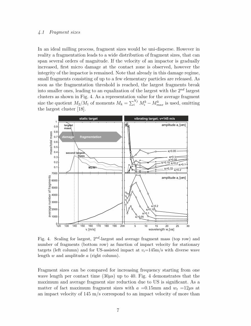
In an ideal milling process, fragment sizes would be uni-disperse. However inreality a fragmentation leads to a wide distribution of fragment sizes, that canspan several orders of magnitude. If the velocity of an impactor is graduallyincreased, first micro damage at the contact zone is observed, however theintegrity of the impactor is remained. Note that already in this damage regime,small fragments consisting of up to a few elementary particles are released. Assoon as the fragmentation threshold is reached, the largest fragments breakinto smaller ones, leading to an equalization of the largest with the 2nd largestclusters as shown in Fig. 4. As a representation value for the average fragment
size the quotient M2/M1 of moments Mk =∑Nf
i Mki −Mk
max is used, omittingthe largest cluster [18].
120 130 140 150 160 170 180 190 200
v [m/s]i
ave
rage n
um
ber
of fr
agm
ents
5 10 15 20 25 300
1000
2000
3000
4000
5000
6000
7000
0.1
0.2
0.3
0.4
0.5
0.6
0.7
0.8
1
second largest mass
damage fragmentation
largest mass
M2/M1
mass
/tota
l mass
0.9
wavelength w [ms]t
static target vibrating target; v=145 m/s
a =0.05t
a =0.1t
a =0.15t
a =0.15t
a =0.15t
a =0.2t
a =0.2t
a=0.1
a =0.1t
a=0.05
a =0.05t
amplitude a [mm]t
t
t
amplitude a [mm]t
a =0.2t
Fig. 4. Scaling for largest, 2nd-largest and average fragment mass (top row) andnumber of fragments (bottom row) as function of impact velocity for stationarytargets (left column) and for US-assisted impact at vi=145m/s with diverse wavelength w and amplitude a (right column).
Fragment sizes can be compared for increasing frequency starting from onewave length per contact time (30µs) up to 40. Fig. 4 demonstrates that themaximum and average fragment size reduction due to US is significant. As amatter of fact maximum fragment sizes with a =0.15mm and wt =12µs atan impact velocity of 145 m/s correspond to an impact velocity of more than
7

200m/s for static targets and the average size to an even higher one. The frag-ment numbers (Fig. 4 bottom) exhibit a similar drastic increase. Interestinglyultrasound can not only promote, but also prohibit fragmentation (see Fig.4(c)wt <3µs). By only looking at the fragment numbers for high frequencies, theopposite would have been expected, however most of the energy is dissipatedby grinding up the contact zone and frictional particle interactions and is nolonger available for crack propagation. This examplefies that a closer look onoccurring fragmentation mechanisms is necessary.
4.2 Fragmentation Process and Mechanisms
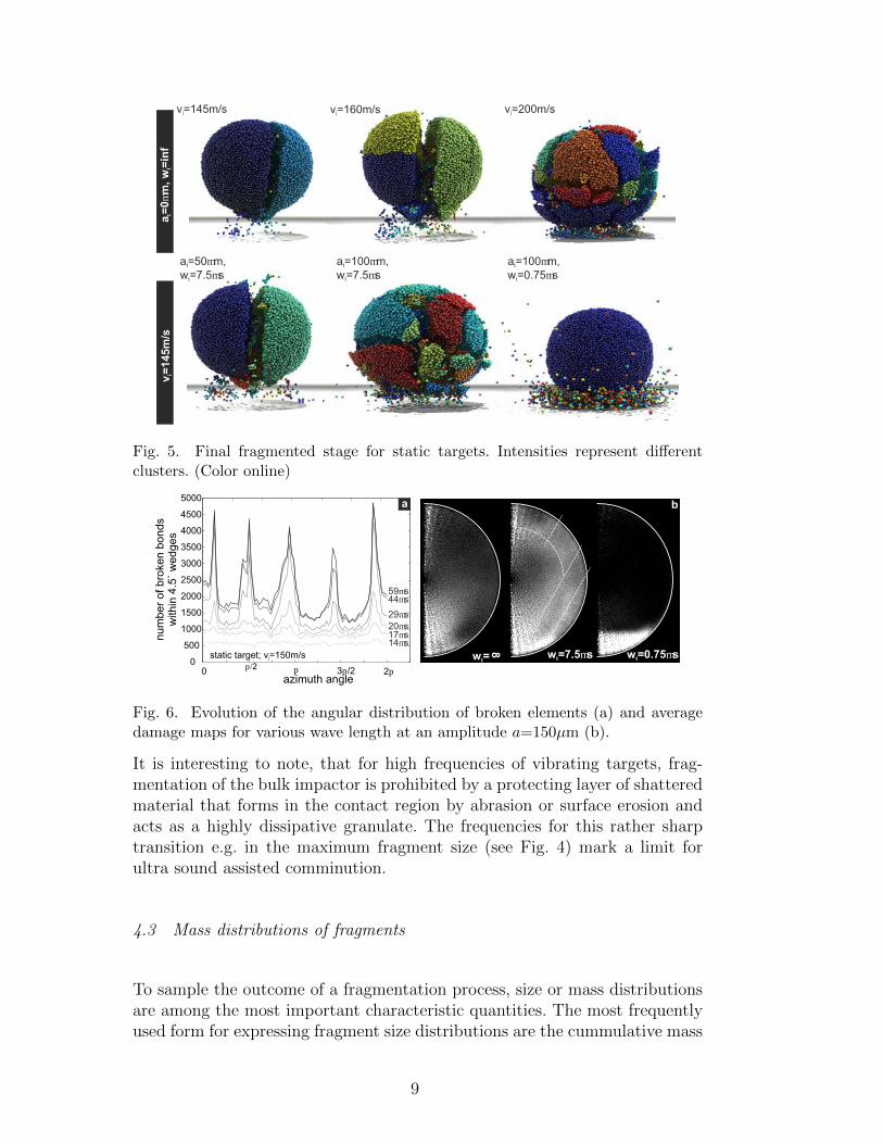
Single particle impact against static targets was subject of experimental [4–9, 12–14] and numeric [1, 16, 21, 24, 35, 36] investigations before. For low ve-locities uncorrelated damage initiates about D/4 from plane inside the spherein the region with the biaxial stress state described before. This zone getsweakened by micro cracks. Around the weakened core, the material has highcircumferential tensile stresses in a ring shaped zone, where meridional cracksoriginate. Since the number of meridional cracks depends on the stress rates,we concluded, that their stress release fields interact like in ring fragmenta-tion [37, 38]. Once initiated, meridional cracks can grow from the inside tothe outside with energy dependent angular separation of wedge shaped frag-ments provided enough energy is imparted [1]. Also a ring of broken bondsis observed, forming a cone, basically by failure due to shear at the contactzone. For higher velocities, oblique cracks further fragment the wedge shapedfragments due to diverse stress states. To summarize, for a static target quasiperiodic sharp meridional cracks splitting the impactor (see Fig. 6a), somefragments at the impact cone and a few one particle fragments are observed.Damage is mainly localized to form large cracks (see Figs. 5,6).
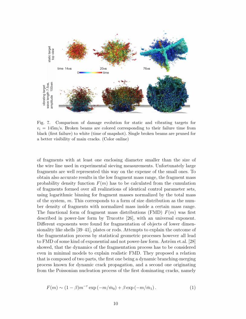
With a vibrating target the emerging fragmentation mechanisms change, de-pending on amplitude and wave length (see Fig.7). Already for small ampli-tudes of 50µm the impact cone gets further fragmented, new fragments formand damage zones widen. Opposite to the case of the static target at identi-cal impact velocity, also inside fragments damage is dispersedly distributed,simplifying further fragmentation e.g. in a secondary comminution step. InFig.5 a case with higher amplitude of 100µm is compared with impact againsta static target at high velocity. It is visible by the naked eye, that fragmentshapes and consequently fragmentation mechanisms differ. For static targets,secondary fragmentation of wedge shaped fragments dominates. The case ofUS-assisted fragmentation is characterized by one front of fractures that growsimultaneously from the bottom to the top, leaving the fragmented systembehind (see Fig. 7).
8
a=
0m
m, w
=in
ft
tv
=145m
/si
v=160m/si v=200m/siv=145m/si
a=50mm,t
w=7.5mst
a=100mm,t
w=7.5mst
a=100mm,t
w=0.75mst
Fig. 5. Final fragmented stage for static targets. Intensities represent differentclusters. (Color online)
w=t w=7.5mst w=0.75mst
8
0p/2 p 3p/2 2p
0
500
1000
1500
2000
2500
3000
3500
4000
4500
5000
azimuth angle
num
ber
of bro
ken b
onds
with
in 4
.5`
wedges
static target; v=150m/si
14ms17ms20ms29ms
44ms59ms
ba
Fig. 6. Evolution of the angular distribution of broken elements (a) and averagedamage maps for various wave length at an amplitude a=150µm (b).
It is interesting to note, that for high frequencies of vibrating targets, frag-mentation of the bulk impactor is prohibited by a protecting layer of shatteredmaterial that forms in the contact region by abrasion or surface erosion andacts as a highly dissipative granulate. The frequencies for this rather sharptransition e.g. in the maximum fragment size (see Fig. 4) mark a limit forultra sound assisted comminution.
4.3 Mass distributions of fragments
To sample the outcome of a fragmentation process, size or mass distributionsare among the most important characteristic quantities. The most frequentlyused form for expressing fragment size distributions are the cummulative mass
9
sta
tic targ
et
top v
iew
vib
ratin
g targ
et
wave
length
7.5m
s,
am
plit
ude 100m
m
14ms 20ms 76mstime
time0
Fig. 7. Comparison of damage evolution for static and vibrating targets forvi = 145m/s. Broken beams are colored corresponding to their failure time fromblack (first failure) to white (time of snapshot). Single broken beams are pruned fora better visibility of main cracks. (Color online)
of fragments with at least one enclosing diameter smaller than the size ofthe wire line used in experimental sieving measurements. Unfortunately largefragments are well represented this way on the expense of the small ones. Toobtain also accurate results in the low fragment mass range, the fragment massprobability density function F (m) has to be calculated from the cumulationof fragments formed over all realizations of identical control parameter sets,using logarithmic binning for fragment masses normalized by the total massof the system, m. This corresponds to a form of size distribution as the num-ber density of fragments with normalized mass inside a certain mass range.The functional form of fragment mass distributions (FMD) F (m) was firstdescribed in power-law form by Trucotte [26], with an universal exponent.Different exponents were found for fragmentation of objects of lower dimen-sionality like shells [39–41], plates or rods. Attempts to explain the outcome ofthe fragmentation process by statistical geometric processes however all leadto FMD of some kind of exponential and not power-law form. Astrom et.al. [28]showed, that the dynamics of the fragmentation process has to be consideredeven in minimal models to explain realistic FMD. They proposed a relationthat is composed of two parts, the first one being a dynamic branching-mergingprocess known for dynamic crack propagation, and a second one originatingfrom the Poissonian nucleation process of the first dominating cracks, namely
F (m) ∼ (1 − β)m−τ exp (−m/m0) + β exp (−m/m1) . (1)
10

The β parameter controls the relative importance of the branching-mergingand Poissonian nucleation process, while the exponent τ only depends on thedimensionality of the system, which is in this case τ3D = (2D−1)/D = 5/3. m0
and m1 are cut of values of the respective parts. For static targets a good fit isobtained for vi = 145m/s when β = 0.99 and for vi = 200m/s when β = 0.01(see Fig. 8). This is in agreement with the observation, that just above thefragmentation threshold the Poissonian fracture nucleation is relevant, whilefor high velocities dynamic branching-merging mechanisms dominate. To an-
-4.5 -4 -3.5 -3 -2.5 -2 -1.5 -1 -0.5 0-4
-3
-2
-1
0
1
2
3
4
5
6
log(F
(m))
30
v=145 m/si
v=145 m/si
amplitude 0.1mm
157.5
1.50.75
3
wave length w [ms]t
0 5 10 15 20 251.6
2
2.5
3
3.5
0.05
wave length w [ms]t
amplitude [mm]
pow
er
law
exp
on
en
t
0.10.150.2
fit for 7.5
fit using Eq.1 with b=0.99
log(m)-4.5 -4 -3.5 -3 -2.5 -2 -1.5 -1 -0.5 0
v=200 m/si
fit using Eq.1 with b=0.01
ba
log(m)
Fig. 8. Fragment mass distributions for static targets (a) and vibrating ones (b).The inset shows the dependences of the power law exponent β for small fragmentmasses with the transition to the shattered phase.
swer the question, which mechanisms dominate in US-assisted fragmentation,the fragment mass distributions are evaluated for various wave lengths wt. Forwt ≈ 30µs, the distributions for static targets hold quite well, while with in-creasing wave length, β has to be reduced to around 0.01 to obtain a good fit.Therefore also in US-assisted fragmentation, branching-merging mechanismsstart to dominate. When a threshold wave length of ≈ 3µs is reached, theexponent of the power law part jumps from 1.67 to significantly higher values,since the contact region is in the shattered phase.
5 Conclusions
It was shown in a realistic 3D DEM simulation, that ultra sonic assisted impactcomminution has a huge potential. The energy transfer into the impactor canbe realized during the short contact time with vertically vibrating targets.Not only the energy increase, but also resulting multiple shock fronts leadto higher degree of comminution and fragmentation mechanisms, that differfrom those of classical impact comminution. The fragment number that canbe obtained with already quite small amplitudes of 50µm is comparable toan increase of impact energy via velocity of about 80%. If the frequencies
11

are above the first eigenmodes, and wave lengths are smaller than the overallcontact time, a considerable amount of energy is pumped into the impactor andavailable for crack propagation. Multiple shock fronts lead to a more uniformdistriubiton of energy and a higher degree of comminution. This goes alongwith a change in observable fragmentation mechanisms. Impact fragmentationagainst static targets lead to oblique cracks and secondary fragmentation ofwedge formed framents. Impact against vibrating targets lead to a strongfragmentation of the cone and contact zone. Fragents form by local crackbranching-merging along a fragmentation front from the bottom to the top. Iffreqencies get to high, the system is pushed back into the damage regime dueto a protective layer of shattered material that forms at the contact zone. Therequired frequencies and amplitudes for the chosen mechanical parameters,that are in the range of lean concrete mixtures, are within the range of off-shelf US-actuators and transducers. To estimate the specific energetic gain ofUS-assisted fragmentation however, one needs to consider the whole chain,including the efficiency of transducers.
References
[1] Carmona H., Wittel F.K., Kun K., Herrmann H.: Fragmentation pro-cesses in impact of spheres. Phys. Rev. E 77, 051302 (2008)
[2] Tavares L.: Optimum routes for particle breakage by impact. PowderTechnol. 142, 81-91 (2004)
[3] Schubert W., Khanal M., Tomas J.: Impact crushing of particle-particlecompounds – experiment and simulation. Int. J. Miner. Process. 75, 41-52(2005)
[4] Tomas J., Schreier M., Groger T., Ehlers S.: Impact crushing of concretefor liberation and recycling. Powder Technol. 105, 39-51 (1999)
[5] Arbiter N., Harris C., Stamboltzis G.: Single fracture of brittle spheres.Trans. Soc. Min. Eng. 244, 118-133 (1969)
[6] Wu S., Chau K., Yu T.: Crushing and fragmentation of brittle spheresunder double impact test. Powder Technol. 143-144, 41-55 (2004)
[7] Andrews E., Kim K.S.: Threshold conditions for dynamic fragmentationof ceramic particles. Mech. Mater. 29, 161-180 (1998)
[8] Antonyuk S., Khanal M., Tomas J., Heinrich S., Morl L.: Impact breakageof spherical granules: Experimental study and DEM simulation. Chem.Engn. Process. 45, 838-856 (2006)
[9] Salman A., Biggs C., Fu J., Angyal I., Szabo M., Hounslow M.: An ex-perimental investigation of particle fragmentation using single particleimpact studies. Powder Technol. 128, 36-46 (2002)
[10] Andrews E., Kim K.S:. Threshold conditions for dynamic fragmentationof glass particles. Mech. Mater. 31, 689-703 (1999)
[11] Cheong Y., Reynolds G., Salman A., Hounslow M.: Modelling fragment
12

size distribution using two-parameter Weibull equation. Int. J. Min. Pro-cess. 74S, S227-S237 (2004)
[12] Salman A., Gorham D.: The fracture of glass spheres. Powder Technol.107, 179-185 (2000)
[13] Majzoub R., Chaudhri M.: High-speed photography of low-velocity im-pact cracking of solid spheres. Philos. Mag. Lett. 80(6), 387-39 (2000)
[14] Schonert K.: Breakage of spheres and circular discs. Powder Technol. 143-144, 2-18 (2004)
[15] Behera B., Kun F., McNamara S., Herrmann H.J.: Fragmentation of acircular disc by impact on a frictionless plate. Condensed Matter 17,S2439-S2456 (2005)
[16] Thornton C., Yin K., Adams M.: Numerical simultion of the impact frac-ture and fragmentation of agglomerates. J. Phys. D: Appl. Phys. 29, 424-435 (1996)
[17] Khanal M., Schubert W., Tomas J.: Ball impact and crack propagation- simulation of particle compound material. Granular Matter 5, 177-184(2004)
[18] Kun F., Herrmann H.J.: A study of fragmentation processes using adiscrete element method. Comp. Methods Appl. Mech. Engn. 138, 3-18(1996)
[19] Kun F., Herrmann H.J.: Transition from damage to fragmentation incollision of solids. Phys. Rev. E 59(3), 2623-2632 (1999)
[20] Kun F., D’Addetta G., Herrmann H.J., Ramm E.: Two-dimensional dy-namic simulation of fracture and fragmentation of solids. Comp. Assist.Mech. Engn. Sci. 6, 385-40 (1999)
[21] Potapov A., Campbell C.: A three-dimensional simulation of brittle solidfracture. Int. J. Mod. Phys. C 7(5), 717-729 (1996)
[22] Potapov A., Campbell C.: Parametric dependence of particle breakagemechanisms. Powder Technol. 120(3), 164-174 (2001)
[23] Kafui K., Thornton C.: Numerical simulations of impact breakage of aspherical crystalline agglomerate. Powder Technol. 109, 113-132 (2000)
[24] Mishra B., Thornton C.: Impact breakage of particle agglomerates. Int.J. Mineral Process. 61, 225-239 (2001)
[25] Odderschede L., Dimon P., Bohr J.: Self-organized criticality in fragmen-tation. PRL 71(19), 3107-3110 (1993)
[26] Turcotte D.: Fractals and fragmentation. Journal of Geophysical Research91(B2), 1921-1926 (1986)
[27] Astrom J., Holian B., Timonen J.: Universality in fragmentation. PRL84(14), 3061-3064 (2000)
[28] Astrom J., Ouchterlony F., Linna R., Timonen J.: Universal fragmenta-tion in d dimensions. PRL 92(24), 245506 (2004)
[29] Astrom J.: Statistical models of brittle fragmentation. Adv. Phys. 55(3-4), 247-278 (2006)
[30] Inaoka H., Takayasu H.: Universal fragment size distribution in a numer-ical model of impact fracture. Physica A 229, 5-25 (1996)
13

[31] Linna R., Astrom J., Timonen J.: Dimensional effects in dynamic frag-mentation of brittle materials. Phys. Rev. E 72, 015601(R) (2005)
[32] Cundall P., Strack O.: A discrete numerical model for granular assemblies.Geotechnique 29(1), 47-65 (1979)
[33] Bicanic N.: Discrete element methods. In: Stein E., de Borst R., HughesT. (eds): Encyclopedia of Computational Mechanics: Fundametals, Cam-bridge University Press, 311-337 (2004)
[34] Barber, C.B., Dobkin, D.P., and Huhdanpaa, H.T.: The Quickhull Al-gorithm for Convex Hulls. ACM Transactions on Mathematical Software22(4), 469-483 (1996), www.qhull.org
[35] Kienzler R., Schmitt W.: On single-particle comminution: Numericalanalysis of compressed spheres. Powder Technol. 61, 29-38 (1990)
[36] Thornton C., Ciomoncos M., Adams M.: Numerical simulation of diamet-rical compression tests on agglomerates. Powder Technol. 140, 258-267(2004)
[37] Molinari J., Gazonas G., Raghupathy R., Rusinek A., Zhou F.: The cohe-sive element approach to dynamic fragmentation: The question of energyconvergence. Int. J. Num. Methods Engn. 69, 484-503 (2007)
[38] Mott N.: Fragmentation of spherical cases. Proc. Royal Society LondonA Math. Phys. Sci. 189, 300-308 (1946)
[39] Kun F., Wittel F.K., Herrmann H.J., Kroplin B.H.: Scaling behavior offragment shapes. PRL 96, 025504 (2006)
[40] Wittel F.K., Kun F., Herrmann H.J., Kroplin B.H.: Fragmentation ofshells. PRL 93(3), 035504 (2004)
[41] Wittel F.K., Kun F., Herrmann H.J., Kroplin B.H.: Breakup of shellsunder explosion and impact. Phys. Rev. E 71, 016108 (2005)
14