single duct terminal units spv, sdv series - price … · all metric dimensions ( ) are soft...
TRANSCRIPT

All Metric dimensions ( ) are soft conversion. © Copyright Price Industries Limited 2014. Imperial dimensions are converted to metric and rounded to the nearest millimetre.
TE
RM
INA
L U
NIT
S
Recommended Air Volume Ranges
Single Duct Terminal UnitsSPV, SDV SeriesSingle Duct – Controller Type
Pneumatic
Unit Size L/s Min.3 L/s Max. cfm Min.3 cfm Max.
4 24 106 50 2255 30 165 63 3506 31 212 66 4507 47 307 99 6508 62 378 132 8009 79 496 167 105010 104 637 221 135012 143 991 304 210014 207 1416 439 300016 268 1888 568 4000
24 x 16 560 3775 1187 8000
Digital Controls
Unit Size L/s Min.4 L/s Max. cfm Min.4 cfm Max.
4 21 189 45 4005 28 236 60 5006 31 260 65 5507 45 378 95 8008 59 519 125 11009 76 661 160 1400
10 99 850 210 180012 142 1227 300 260014 203 1746 430 370016 271 2360 575 5000
24 x 16 559 3964 1185 8400
Notes:1. Factory calibrated controls must be selected within the
above flow range limits. A minimum value of 0 is also available. When an auxiliary flow setting is specified, the value must be greater than the minimum setting and within the range limits.
2. On controls mounted by Price but supplied by others, the air volume ranges are guidelines only.
3. Minimum airflow limit for pneumatic controls is based onmin0.02 in.w.g. [5Pa]differentialpressuresignalfrom airflow sensor. Maximum airflow limit is based on max1.0in.w.g.[249Pa]differentialpressuresignalfromthe airflow sensor.
4. Minimum airflow limit for digital controls is based on min 0.02in.w.g.[5Pa]differentialpressuresignalfromairflowsensor. Maximum airflow limit is based on max 1.5 in. w.g. [373Pa]differentialpressuresignalfromairflowsensor.
5. Selection of airflow limits outside the listed values is not recommended. Stability and accuracy may not be acceptable at lower than recommended airflow limits. The actual performance will vary depending on the terminal unit controls supplied.
F-60

© Copyright Price Industries Limited 2014. All Metric dimensions ( ) are soft conversion. Imperial dimensions are converted to metric and rounded to the nearest millimetre.
TE
RM
INA
L U
NIT
S
Single Duct Terminal UnitsSPV, SDV SeriesSingle Duct – Controller Type
Discharge NC Basic Unit
∆Ps Across Unit
Discharge NC c/w 36 in. Attenuator ∆Ps Across Unit
Radiated NC Basic Unit
∆Ps Across UnitMinimum ∆Ps
Across Assembly Min. ∆Pt. 0.5 in. 1.5 in. 3.0 in. 0.5 in. 1.5 in. 3.0 in. 0.5 in. 1.5 in. 3.0 in. Unit Airflow Basic Unit w/Atten. 1 Row Coil 2 Row Coil Basic Unit in.w.g in.w.g in.w.g in.w.g in.w.g in.w.g in.w.g in.w.g in.w.gSize cfm L/s in.w.g Pa in.w.g Pa in.w.g Pa in.w.g Pa in.w.g Pa 125Pa 375Pa 750Pa 125Pa 375Pa 750Pa 125Pa 375Pa 750Pa
4 75 35 0.01 2 0.01 2 0.02 5 0.03 7 0.06 14 -- -- -- -- -- -- -- -- --150 71 0.01 2 0.01 2 0.04 10 0.06 15 0.19 48 29 29 29 21 24 26 -- -- --200 94 0.01 2 0.01 2 0.05 12 0.1 25 0.33 83 35 35 35 26 29 31 21 22 23300 142 0.01 2 0.01 2 0.1 25 0.2 50 0.74 184 40 40 40 28 31 33 29 31 31400 189 0.01 2 0.01 2 0.16 40 0.33 82 1.31 325 46 46 47 33 36 38 35 36 37
5 125 59 0.01 2 0.01 2 0.03 7 0.05 12 0.06 15 -- -- 20 -- -- -- -- -- --250 118 0.01 2 0.01 2 0.08 20 0.15 37 0.21 53 24 30 33 -- 24 28 -- 20 23300 142 0.01 2 0.01 2 0.1 25 0.2 50 0.3 75 23 29 32 -- 23 27 -- 24 27400 189 0.01 2 0.01 2 0.16 40 0.33 82 0.53 131 27 34 38 -- 27 31 22 29 32500 236 0.01 2 0.01 2 0.24 60 0.49 122 0.82 203 31 38 42 22 30 34 26 32 36
6 150 71 0.02 5 0.02 5 0.05 12 0.07 18 0.05 13 -- 20 23 -- -- -- -- -- --225 106 0.05 12 0.05 12 0.1 25 0.16 40 0.13 31 20 26 30 -- 20 24 -- -- 20300 142 0.08 20 0.08 20 0.17 42 0.27 68 0.21 53 21 27 31 -- -- 23 -- 21 25400 189 0.14 35 0.14 35 0.29 72 0.46 114 0.38 94 26 36 36 -- 23 27 20 26 29550 260 0.27 67 0.27 67 0.54 134 0.84 209 0.72 179 31 37 41 21 27 31 25 31 34
7 250 118 0.02 4 0.02 4 0.06 15 0.1 25 0.07 16 -- 23 26 -- -- 20 -- -- --350 165 0.03 8 0.03 8 0.1 25 0.18 45 0.13 32 -- 24 28 -- -- 21 -- -- 20550 260 0.07 18 0.07 18 0.23 57 0.41 102 0.31 77 25 31 36 -- 24 28 -- 24 27625 295 0.1 25 0.1 25 0.3 75 0.53 132 0.41 101 27 33 38 -- 25 30 20 25 29800 378 0.16 40 0.16 40 0.48 119 0.83 207 0.66 165 28 36 41 20 27 32 23 28 33
8 400 189 0.01 2 0.01 2 0.1 25 0.2 50 0.08 19 -- 22 26 -- -- 21 -- -- 21500 236 0.01 2 0.01 2 0.15 37 0.3 75 0.12 29 20 26 30 -- -- 24 -- -- 24700 330 0.01 2 0.01 2 0.26 65 0.53 132 0.22 54 26 31 36 -- 24 28 -- 24 29900 425 0.01 2 0.01 2 0.4 100 0.83 207 0.35 88 27 34 38 -- 24 29 22 28 33
1100 519 0.01 2 0.01 2 0.57 142 1.19 296 0.52 130 31 37 41 -- 27 32 26 31 369 450 212 0.01 2 0.01 2 0.07 17 0.13 32 0.07 16 -- 22 28 -- -- 25 -- -- 22
700 330 0.01 2 0.01 2 0.14 35 0.27 67 0.15 36 -- 26 33 -- 22 28 -- 21 26900 425 0.01 2 0.01 2 0.21 52 0.43 107 0.23 58 20 27 34 -- 22 29 -- 23 29
1100 519 0.01 2 0.01 2 0.29 72 0.61 152 0.35 86 23 30 37 -- 24 30 -- 25 311400 661 0.01 2 0.01 2 0.45 112 0.93 231 0.55 138 26 33 39 -- 26 32 20 28 33
10 550 260 0.01 2 0.01 2 0.09 22 0.18 45 0.06 15 -- 21 28 -- -- 23 -- -- 22950 448 0.01 2 0.01 2 0.23 57 0.47 117 0.16 40 -- 26 32 -- 21 27 -- 22 28
1100 519 0.01 2 0.01 2 0.29 72 0.61 152 0.21 53 -- 28 34 -- 23 28 -- 24 301500 708 0.01 2 0.01 2 0.51 127 1.06 264 0.39 96 23 31 38 -- 26 32 21 27 331800 850 0.01 2 0.01 2 0.7 174 1.46 363 0.55 138 25 34 40 20 28 34 23 30 35
12 900 425 0.01 2 0.01 2 0.12 30 0.25 62 0.07 18 -- 21 29 -- -- 25 -- 20 261200 566 0.01 2 0.01 2 0.2 50 0.41 102 0.12 31 -- 24 31 -- 22 28 -- 24 291600 755 0.01 2 0.01 2 0.33 82 0.68 169 0.21 53 -- 26 33 -- 24 31 -- 26 321800 850 0.01 2 0.01 2 0.4 100 0.83 207 0.27 66 -- 28 34 -- 25 32 -- 28 342600 1227 0.01 2 0.01 2 0.77 192 1.61 401 0.54 135 21 32 38 21 30 36 23 32 38
14 1000 472 0.01 2 0.01 2 0.08 20 0.15 37 0.05 13 -- -- 27 -- 23 30 -- -- 261500 708 0.01 2 0.01 2 0.15 37 0.31 77 0.11 27 -- 22 30 -- 25 32 -- 23 302100 991 0.01 2 0.01 2 0.27 67 0.56 139 0.2 51 -- 26 33 -- 28 35 -- 26 342700 1274 0.01 2 0.01 2 0.42 105 0.88 219 0.33 82 -- 28 35 -- 29 36 -- 29 363700 1746 0.01 2 0.01 2 0.74 184 1.54 383 0.61 152 20 31 38 20 32 39 23 33 40
16 1500 708 0.01 2 0.01 2 0.11 27 0.23 57 0.07 17 -- 20 28 -- 21 29 -- 22 292000 944 0.01 2 0.01 2 0.18 45 0.37 92 0.11 27 -- 23 31 -- 24 32 -- 25 322600 1227 0.01 2 0.01 2 0.29 72 0.59 147 0.18 45 -- 26 33 -- 26 34 -- 28 353200 1510 0.01 2 0.01 2 0.41 102 0.86 214 0.27 66 -- 28 35 -- 28 36 20 31 384000 1888 0.01 2 0.01 2 0.61 152 1.28 319 0.41 102 -- 30 37 -- 31 38 23 33 405000 2360 0.01 2 0.01 2 0.91 226 1.9 473 0.64 158 20 32 40 21 33 40 26 36 43
24x16 3000 1416 0.01 2 0.01 2 0.17 42 0.34 85 0.06 16 23 32 37 -- 27 32 24 31 354000 1888 0.01 2 0.01 2 0.27 67 0.56 139 0.11 26 27 35 41 23 31 36 29 35 395300 2501 0.01 2 0.01 2 0.45 112 0.93 231 0.18 44 30 39 44 27 35 40 30 39 436000 2832 0.01 2 0.01 2 0.56 139 1.16 289 0.23 56 32 41 46 28 37 42 31 41 457000 3304 0.01 2 0.01 2 0.73 182 1.53 381 0.3 76 34 42 48 30 39 44 32 43 478400 3964 0.01 2 0.01 2 1.01 251 2.12 528 0.43 108 36 45 50 33 41 46 33 46 50
Typical Selection Guide
Performance Notes:1. NC's are derived from sound power levels, which are
obtained in accordancewithAHRI Standard 880-2011andASHRAEStandard130-2008.
2. Airflow is given in cubic feet per minute, CFM; and litres per second, L/s.
3. Blank spaces (----) indicate NC's less than 20.4. Asterisks indicate minimum static pressure of unit exceed
the minimum opeating pressure across the unit.5. ∆P's is the difference in static pressure from inlet to
discharge of the unit.6. ∆Pt is the difference in total pressure from inlet to
discharge of the unit.7. Pressure is given in Pascals, Pa and inches of water
gauge in w.g.
Discharge NC is based on environmental effect, end re-flection, flex duct, sound power division and lined duct per AHRI885-2008attenuationvaluesDischarge SoundTotal Deduction Octave Band Mid Frequency, Hz
120 250 500 1000 2000 4000< 300 cfm 24 28 39 53 59 40300-700cfm 27 29 40 51 53 39>700cfm 29 30 41 51 52 39
For detailed explanation of the NC calculation refer to en-gineering guide.
8. NC values are calculated based on typical attenuation valuesoutlinedinAppendixE,AHRIStandard885-2008,"A Procedure for Estimating Occupied Space Sound Levels in the Application of Air Terminals and Air Outlets."
RadiatedNCisbasedon5/8"mineralfibertileceilingperAHRI885-2008attenuationvalues.Radiated SoundTotal Deduction Octave Band Mid Frequency, Hz
120 250 500 1000 2000 4000All Sizes 18 19 20 26 31 36
F-61

All Metric dimensions ( ) are soft conversion. © Copyright Price Industries Limited 2014. Imperial dimensions are converted to metric and rounded to the nearest millimetre.
TE
RM
INA
L U
NIT
S
Single Duct Terminal UnitsSPV, SDV SeriesSingle Duct – Controller Type
Typical Selection Guide
NC levels presented in the Typical Selection Guide are based on typical attenuation values as outlined in AHRI Standard 885-2008, Appendix E. AHRI Standard 885-2008, Appendix E provides typical sound attenuation values for air terminal discharge sound and air terminal radiated sound. The typical attenuation values are recommended for use by manufacturers to estimate application sound levels.
In product catalogs the end use environments are not known and the factors presented in AHRI Standard 885-2008 are provided as typical attenuation values. Use of these values will allow better comparison between manufacturers and give the end user a value which will be expected to be applicable for many types of spaces.
Following is a detailed description of the typical attenuation values used to determine NC levels on page F62.
Radiated SoundTable E-1 of Appendix E provides typical radiated sound attenuation values for three types of ceilings: Type 1 – Glass Fiber; Type 2 – Mineral Fiber; Type 3 – Solid Gypsum Board.
Since Mineral Fiber tile ceilings are the most common construction used in commercial buildings, the attenuation values in the Typical Selection Guide are based on Type 2 – Mineral Fiber.
The following table provides the calculation method for the radiated sound total attenuation values based on AHRI Standard 885-2008.
Octave Band Mid Frequency, Hz
125 250 500 1000 2000 4000
Environmental Effect 2 1 0 0 0 0
Ceiling/Space Effect 16 18 20 26 31 36
Total Attenuation Deduction 18 19 20 26 31 36
The ceiling/space effect assumes the following conditions:
1. 5/8 in. [16mm] tile, 20 lb/ft3 [320 kg/m3] density2. The plenum is at least 3 ft [0.9m] deep3. The plenum space is either wide (over 30 ft [9.1m]) or lined with
insulation4. The ceiling has no significant penetration directly under the
unit.
Discharge SoundTable E-1 of Appendix E provides typical discharge sound attenuation values for three sizes of terminal units.
1. Small box – defined as a unit with discharge duct of approximately 8 in. x 8 in. [203 x 203] and capacity less than 300 cfm [142 L/s].
2. Medium box – defined as a unit with discharge duct of approximately 12 in. x 12 in. [305 x 305] and capacity between 300 – 700 cfm [142-330 L/s].
3. Large box – defined as a unit with discharge duct of approximately 15 in. x 15 in. [381 x 381] and capacity of greater than 700 cfm [330 L/s].
The following tables provide the calculation method for the discharge sound and total attenuation values based on AHRI Standard 885-2008.
Small Box Octave Band Mid Frequency, Hz
(< 300 cfm) 125 250 500 1000 2000 4000
Environmental Effect 2 1 0 0 0 0
5 ft [1.5 m] Duct Lining 2 6 12 25 28 18
End Reflection 9 5 2 0 0 0
5 ft [1.5 m], 8 in [203 mm]Flex Duct 6 10 18 20 21 12
Space Effect 5 6 7 8 9 10
Sound Power Division 0 0 0 0 0 0
Total Attenuation Deduction 24 28 39 53 58 40
Medium Box Octave Band Mid Frequency, Hz
(300 – 700 cfm) 125 250 500 1000 2000 4000
Environmental Effect 2 1 0 0 0 0
5 ft [1.5 m] Duct Lining 2 4 10 20 20 14
End Reflection 9 5 2 0 0 0
5 ft [1.5 m], 8 in [203 mm]Flex Duct 6 10 18 20 21 12
Space Effect 5 6 7 8 9 10
Sound Power Division 3 3 3 3 3 3
Total Attenuation Deduction 27 29 40 51 53 39
Large Box Octave Band Mid Frequency, Hz
(> 700 cfm) 125 250 500 1000 2000 4000
Environmental Effect 2 1 0 0 0 0
5 ft [1.5 m] Duct Lining 2 3 9 18 17 12
End Reflection 9 5 2 0 0 0
5 ft [1.5 m], 8 in [203 mm]Flex Duct 6 10 18 20 21 12
Space Effect 5 6 7 8 9 10
Sound Power Division 5 5 5 5 5 5
Total Attenuation Deduction 29 30 41 51 52 39
For a complete explanation of the attenuation factors and the procedures for calculating room NC levels, please refer to AHRI Standard 885-2008.
F-62

© Copyright Price Industries Limited 2014. All Metric dimensions ( ) are soft conversion. Imperial dimensions are converted to metric and rounded to the nearest millimetre.
TE
RM
INA
L U
NIT
S
Single Duct Terminal UnitsSPV, SDV SeriesSingle Duct – Controller Type
Typical Selection Guide
NC vs Sound Power Levels – Compare Them CarefullyPrice represents the sound performance data for the SPV/SDV series of single duct terminals in two manners.
The laboratory attained discharge and radiated sound power levels for each unit at various flows and inlet static pressures is presented in the Acoustical Data tables. This data is derived in accordance with AHRI Standard 880 and shows the 'raw' sound power levels of the terminal in the second through seventh octave bands with NO attenuation allowances. This data includes AHRI standard ratings which are on record with the Air-Conditioning Refrigeration Institute.
Price also offers this Typical Application and Selection Guide to assist you in selecting the proper size and configuration of terminal for your needs. The attenuation allowances listed are based on values suggested in AHRI Standard 885-2008, Appendix E. The suggested attenuation allowances are intended to be representative of typical jobsite construction. If your conditions differ significantly from these it is recommended you utilize the sound power level data on pages F68-F70 and the procedures outlined in AHRI Standard 885-2008.
If the NC levels listed in the Price catalog are being compared to other manufacturers’ cataloged NC information, a careful review of the other manufacturers’ attenuation allowances must be made. If allowances other than recommended AHRI Standard 885-2008, Appendix E are used, a fair comparison of NC levels cannot be performed.
Pressure Drop Explanation1. ∆Ps is the static pressure drop across the terminal unit from the
inlet to the discharge.2. Minimum ∆Ps across the unit is the pressure drop across the
terminal unit from the inlet to the discharge with the damper in full open position. The minimum ∆Ps must be maintained in order to supply the rated airflow through the terminal unit.
Minimum ∆Ps values are provided for the basic assembly only and for the basic assembly combined with accessories such as attenuator and hot water coils.
The minimum ∆Ps across the terminal unit and accessories does not include resistance of the downstream ductwork or diffusers. To determine the minimum inlet static pressure required to achieve rated airflow the downstream resistance must be added to the minimum ∆Ps.
3. ∆Pt is the total pressure drop across the terminal unit from the inlet to the discharge. Total pressure includes both the static pressure drop and velocity pressure drop. Velocity pressure drop is due to the reduced duct velocity at the terminal unit discharge.
4. NC at ∆Ps across the unit is the NC level produced by the terminal unit with the listed static pressure drop from the inlet to the discharge (∆Ps). The listed ∆Ps is the excess static pressure removed by the terminal unit damper.
F-63

All Metric dimensions ( ) are soft conversion. © Copyright Price Industries Limited 2014. Imperial dimensions are converted to metric and rounded to the nearest millimetre.
TE
RM
INA
L U
NIT
S
Single Duct Terminal UnitsSPV, SDV SeriesSingle Duct – Controller Type
Selection Procedure
The selection of the terminal unit will be based on the minimum and maximum primary airflows determined to satisfy the space requirements. The maximum flow is determined by the space cooling load while the minimum flow is determined form the ventilation rate per ASHRAE Standard 62 – 2004 or the space heating load.
Price single duct terminals are offered with inlet valve sizes ranging from 4" [102] round to 24”x16” [610 x 406]. Each inlet size has a specific air volume range based on the minimum flow which can be accurately controlled to the maximum flow which will maintain reasonable pressure loss and noise level. Recommended air volume ranges are cataloged for each inlet valve size. Usually several inlet valve sizes will accommodate a particular set of minimum and maximum design flows .
A common practice is to select the largest inlet valve size possible in order to reduce the terminal generated sound. While this practice may appear to reduce catalog noise levels this is not necessarily true. The larger size terminal will normally have a lower minimum operating pressure drop requiring the valve damper to throttle more at a given inlet static pressure. The more closed or pinched a valve damper is for a given inlet static pressure, the more sound it will generate. See Figure A for an example.
Another disadvantage of an oversized selection is equipment cost as a larger size unit is generally more expensive. All accessories such as reheat coils and attenuators of an oversized unit will add to this cost disadvantage.
Pressure independent terminals (VAV) need to control at both the maximum airflow as well as the minimum airflow. The recommended maximum and minimum flow rates are intended to allow any controller to properly resolve the airflow signal and provide the opportunity for control. It is possible when a damper is mostly closed (at low flows), the control accuracy may be degraded as the damper actuator is only using a fraction of the damper travel or stroke and small changes in damper position may generate significant changes in air volume
It is recommended that the terminal unit valve be sized for 75 to 80% of the rated air volume capacity. Minimum flow rates should be around 20% of the rated air volume for the most accurate level of control.
Should an inlet valve be oversized, another issue may arise if optional electric heaters are installed. At low flows, there may not be sufficient total pressure to activate and maintain the closure of the airflow safety switch, which can easily the to nuisance tripping of the thermal safety switch.
Minimum Inlet Static PressureIn order to size the fan system the minimum inlet static pressure at the terminal unit must be determined.
The minimum static pressure at the inlet of a single duct terminal unit includes the pressure drop across the unit, the pressure drop across any accessories, plus the pressure drop of the downstream ductwork and diffusers. The minimum static pressures of the terminal units and hot water coils are listed in the typical selection guide. The resistance of electric coils can be considered to be negligible. Providing higher static pressure than required at the terminal inlet will cause the valve damper to throttle more, increasing the terminal generated sound.
Min. Press.
Min. Press. +0.25”
Min. Press. +1.0”
Min. Press. +0.5”
Min. Press. +6.0”
Min. Press. +3.0”
Min. Press. +1.5”
10
20
30
40
50
60
70
80
90
0 125 250 500 1000 2000 4000
Radi
ated
Sou
nd P
ower
Leve
l (dB
)
Octave Band Center Frequency
10
20
30
40
50
60
70
80
90
0 125 250 500 1000 2000 4000
Disc
harg
e So
und
Pow
er Le
vel (
dB)
Octave Band Center Frequency
Acoustical Selection ProcedurePlease refer to the Acoustical Selection Procedure on page F14 of the engineering guide.
Figure A: 1800 cfm Single Duct Terminal, 12” inlet
F-64

© Copyright Price Industries Limited 2014. All Metric dimensions ( ) are soft conversion. Imperial dimensions are converted to metric and rounded to the nearest millimetre.
TE
RM
INA
L U
NIT
S
Selection Example Single Duct Terminal
Single Duct Terminal UnitsSPV, SDV SeriesSingle Duct – Controller Type
Heat Source (Per Office) Imperial Metric
Occupants (two) 2 x 250 = 500 Btu/h 146W
Computer 308Btu/h 90W
Lighting 12x15x6.82=1228Btu/h 3.7x4.6x21.5=366W
Exterior Solar/Conduction 15 x 9 x 5 = 900 Btu/h 2.7x4.6x16=199W
Total 2711Btu/h 801W
Single Duct Selection, Reheat The office zone in the following example consists of three offices, each measuring 15 ft (4.6m) long by 12 ft (3.7m) wide by 9 ft (2.7m) tall with a floor-to-floor height of 12 ft (3.7m). The offices are served by a single terminal unit mounted above the hallway ceiling. Design conditions for the zone will include two occupants in each room with a single computer with LCD monitor. The offices are all lit by T8 fluorescent lighting and the control temperature will be 75 °F (24°C) during the day and 65 °F (18°C) at night.
Space Considerations• Heatloadsourcesforeachofficespace: qex = Heat gain from exterior surfaces (Summer), estimated
to be 5 Btu/h ft2 [16 W/m2]* qex = Heat loss from exterior surfaces (Winter), estimated
to be 8 Btu/h ft2 [25 W/m2]* qoe = Heat load of occupants (2 people, 250 Btu/h [73W])
and equipment (308 Btu/h) [90W] ql = Heat gain due to lighting, estimated at 6.82 Btu/h ft2
[21.5 W/m2] *This heat load should be calculated based on the
specific building shell construction• Supplyairconditions: Tsa = Supply air temperature (cooling mode), 55 °F [13°C] Tsa = Supply air temperature (heating mode), 95 °F [35°C] Trs,d = Daytime room set-point, 75 °F [24°C] cp = Specific heat of air at constant pressure, 0.24 Btu/lb°F ρ = Density of air, 0.075 lb/ft3
The first step is to determine the airflow rate (Q) for cooling conditions:
Thermostat15 ft
Supply Air
Sing
le D
uct T
erm
inal
Then, determine the minimum outdoor air ventilation airflow:
where:Rp = the outdoor air requirement per person, 5 cfm [2.4 L/s]
(Table 6-1, ASHRAE Standard 62.1-2004).Ra = the outdoor air requirement per ft2 of floor space,
0.06 cfm/ft2 [0.3(L/s)/m2] (Table 6-1, ASHRAE Standard 62.1-2004).
Pz = Number of zone occupantsEz = the ventilation effectiveness, assumed to be 1.0 for a
mixing systemAz = (12)(15)=180 ft2
Az = (3.7)(4.6)=17 m2
Assuming that the air handling unit provides supply air at a ratio of 25% outdoor air and 75% recirculated air, the actual box minimum must be four times the value of Q(min,oa) above to meet the outdoor air ventilation requirements. Therefore:
Qmin = 4(Qmin,oa ) = 250 cfm
The heat loss from the space in the winter must also be considered. Taking the exterior heat loss to be -8 Btu/h/ft2 [25 W/m2], the heat loss on a winter night (no people/equipment, lights off) is found to be 1440 Btu/h [422 W] per office.
Assuming a reheat supply air temperature of 95 °F [35°C] and a room temperature of 75 °F [24°C]:
Since the required reheat airflow is less than the minimum ventilation airflow, the reheat flow rate will need to be equal to the unoccupied night air volume to properly heat the space in the winter. Assuming a desired heating supply temperature of 95 °F ,the reheat capacity can be calculated as:
*Note: metric and imperial values differ due to rounding error𝒬𝒬!"# =
𝑞𝑞!" + 𝑞𝑞! + 𝑞𝑞!"𝜌𝜌 𝑐𝑐!∆𝑇𝑇
=3(801𝑊𝑊)
1.2 𝑛𝑛𝑛𝑛𝑚𝑚! 1 𝑛𝑛𝑛𝑛𝑛𝑛𝑛𝑛 ∙ 𝐾𝐾 11𝐾𝐾
= 182 𝐿𝐿/𝑠𝑠
𝒬𝒬!"#,!" = 3(𝑅𝑅!𝑃𝑃! + 𝑅𝑅!𝐴𝐴!)
𝐸𝐸!=3( 24 2 + (0.3)(17)
1.0 = 30 𝐿𝐿/𝑠𝑠
𝒬𝒬!"# = 4 𝒬𝒬!"#,!" = 4 30 = 120 𝐿𝐿/𝑠𝑠
𝒬𝒬!"#!!,! =𝑞𝑞!"
𝜌𝜌 ∙ 𝐶𝐶! ∙ ∆𝑇𝑇=
3 422𝑊𝑊
1.2 𝑛𝑛𝑛𝑛𝑚𝑚! 1 𝑛𝑛𝑛𝑛𝑛𝑛𝑛𝑛 ∙ 𝐾𝐾 11𝐾𝐾
= 95𝐿𝐿/𝑠𝑠
𝑞𝑞!"!!"# = 𝒬𝒬!"#!!,! ∙ 𝜌𝜌 ∙ 𝐶𝐶! ∙ ∆𝑇𝑇 = 95 1.2 1 22 = 2508𝑊𝑊 = 2.5𝑘𝑘𝑊𝑊
𝒬𝒬!"# =𝑞𝑞!" + 𝑞𝑞! + 𝑞𝑞!"
𝜌𝜌 𝑐𝑐!∆𝑇𝑇=
3(801𝑊𝑊)
1.2 𝑛𝑛𝑛𝑛𝑚𝑚! 1 𝑛𝑛𝑛𝑛𝑛𝑛𝑛𝑛 ∙ 𝐾𝐾 11𝐾𝐾
= 182 𝐿𝐿/𝑠𝑠
𝒬𝒬!"#,!" = 3(𝑅𝑅!𝑃𝑃! + 𝑅𝑅!𝐴𝐴!)
𝐸𝐸!=3( 24 2 + (0.3)(17)
1.0 = 30 𝐿𝐿/𝑠𝑠
𝒬𝒬!"# = 4 𝒬𝒬!"#,!" = 4 30 = 120 𝐿𝐿/𝑠𝑠
𝒬𝒬!"#!!,! =𝑞𝑞!"
𝜌𝜌 ∙ 𝐶𝐶! ∙ ∆𝑇𝑇=
3 422𝑊𝑊
1.2 𝑛𝑛𝑛𝑛𝑚𝑚! 1 𝑛𝑛𝑛𝑛𝑛𝑛𝑛𝑛 ∙ 𝐾𝐾 11𝐾𝐾
= 95𝐿𝐿/𝑠𝑠
𝑞𝑞!"!!"# = 𝒬𝒬!"#!!,! ∙ 𝜌𝜌 ∙ 𝐶𝐶! ∙ ∆𝑇𝑇 = 95 1.2 1 22 = 2508𝑊𝑊 = 2.5𝑘𝑘𝑊𝑊 𝒬𝒬!"# =
𝑞𝑞!" + 𝑞𝑞! + 𝑞𝑞!"𝜌𝜌 𝑐𝑐!∆𝑇𝑇
=3(801𝑊𝑊)
1.2 𝑛𝑛𝑛𝑛𝑚𝑚! 1 𝑛𝑛𝑛𝑛𝑛𝑛𝑛𝑛 ∙ 𝐾𝐾 11𝐾𝐾
= 182 𝐿𝐿/𝑠𝑠
𝒬𝒬!"#,!" = 3(𝑅𝑅!𝑃𝑃! + 𝑅𝑅!𝐴𝐴!)
𝐸𝐸!=3( 24 2 + (0.3)(17)
1.0 = 30 𝐿𝐿/𝑠𝑠
𝒬𝒬!"# = 4 𝒬𝒬!"#,!" = 4 30 = 120 𝐿𝐿/𝑠𝑠
𝒬𝒬!"#!!,! =𝑞𝑞!"
𝜌𝜌 ∙ 𝐶𝐶! ∙ ∆𝑇𝑇=
3 422𝑊𝑊
1.2 𝑛𝑛𝑛𝑛𝑚𝑚! 1 𝑛𝑛𝑛𝑛𝑛𝑛𝑛𝑛 ∙ 𝐾𝐾 11𝐾𝐾
= 95𝐿𝐿/𝑠𝑠
𝑞𝑞!"!!"# = 𝒬𝒬!"#!!,! ∙ 𝜌𝜌 ∙ 𝐶𝐶! ∙ ∆𝑇𝑇 = 95 1.2 1 22 = 2508𝑊𝑊 = 2.5𝑘𝑘𝑊𝑊
𝒬𝒬!"# =𝑞𝑞!" + 𝑞𝑞! + 𝑞𝑞!"
𝜌𝜌 𝑐𝑐!∆𝑇𝑇=
3(801𝑊𝑊)
1.2 𝑛𝑛𝑛𝑛𝑚𝑚! 1 𝑛𝑛𝑛𝑛𝑛𝑛𝑛𝑛 ∙ 𝐾𝐾 11𝐾𝐾
= 182 𝐿𝐿/𝑠𝑠
𝒬𝒬!"#,!" = 3(𝑅𝑅!𝑃𝑃! + 𝑅𝑅!𝐴𝐴!)
𝐸𝐸!=3( 24 2 + (0.3)(17)
1.0 = 30 𝐿𝐿/𝑠𝑠
𝒬𝒬!"# = 4 𝒬𝒬!"#,!" = 4 30 = 120 𝐿𝐿/𝑠𝑠
𝒬𝒬!"#!!,! =𝑞𝑞!"
𝜌𝜌 ∙ 𝐶𝐶! ∙ ∆𝑇𝑇=
3 422𝑊𝑊
1.2 𝑛𝑛𝑛𝑛𝑚𝑚! 1 𝑛𝑛𝑛𝑛𝑛𝑛𝑛𝑛 ∙ 𝐾𝐾 11𝐾𝐾
= 95𝐿𝐿/𝑠𝑠
𝑞𝑞!"!!"# = 𝒬𝒬!"#!!,! ∙ 𝜌𝜌 ∙ 𝐶𝐶! ∙ ∆𝑇𝑇 = 95 1.2 1 22 = 2508𝑊𝑊 = 2.5𝑘𝑘𝑊𝑊
1440
2711377
F-65

All Metric dimensions ( ) are soft conversion. © Copyright Price Industries Limited 2014. Imperial dimensions are converted to metric and rounded to the nearest millimetre.
TE
RM
INA
L U
NIT
S
Single Duct Terminal UnitsSPV, SDV SeriesSingle Duct – Controller Type
Selecting an Electric Reheat Coil:The previous calculations have determined that 2.5 kW of reheat is required from the electric heater. In order to select this heater, two additional parameters must be known: the input voltage/phase to the heater, and the control method. If a single-stage heater of 480 volt, three-phase input power is assumed, the following calculations can be made in the AIO software.
A limiting factor in electric coil selection can be the current draw of the heater, which can be calculated as:
This agrees with the data in the example above. Generally, special considerations are required when coils draw more than 48 amps.
An additional point to consider: electric coils have a minimum flow requirement of 70 cfm/kW (33 L/s per kW). Failure to do so may result in hot spots along the coil, where repeated overheating may lead to thermal fatigue and eventual coil failure.
Single Duct Terminal Unit Selection:The first step in selecting a single duct terminal unit is to choose the inlet or valve size. This is generally dependent on the value of both the maximum and the minimum cooling airflow for the zone. Using the Price Terminal Unit Catalog and comparing inlet valve sizes vs. air volume ranges shows that the size 6 in. (152mm) and 8 in. (203mm) are in the desired range of operation.
The lowest inlet velocity that the single duct sensor can reliably and repeatedly control is based on a Vp signal of 0.02 in. w.g. (50 Pa). For an 8 in. (203mm) valve this is 132 cfm (62 L/s). This value is the lowest cfm that the terminal unit/controller assembly can reliably control, meaning that the unit minimum should be selected higher than this value to ensure the full minimum airflow is delivered to the space.
Note: these lower minimum cfm values for the various inlet sizes are based on data from the manufacturer of the flow sensor. A typical lower limit for the airflow velocity that will provide a strong pressure signal is 400 fpm (2 m/s).
Reheat Coil Selection:Many applications require the use of reheat coils on terminal units. These may be hot water, steam or electrical heating coils. These coils reheat the air when required to satisfy the space requirements.
Selecting a Hot Water Reheat Coil:Based on the calculations above, the zone requires 8.6 MBH at a reheat airflow of 200 cfm (94 L/s). Using Price’s All-In-One software (shown below), to determine the necessary coil (see below), a one-row coil flowing 0.79 gpm (0.05 L/s) will satisfy the MBH and LAT requirements for the supply air to the space. Since the calculation below is based on water at an EWT of 180 °F (82°C), other fluid types and different temperatures will alter the performance selection.
Additionally, the air-side and water-side pressure drops must be reviewed to ensure that the system equipment (AHU, water pump) will be able to handle them. This example results in an air-side pressure drop of 0.08 in. w.g. (20 Pa) at minimum cfm, and a water-side pressure drop of 0.4 ft. w.g. (1.2 kPa) at full fluid flow of 0.79 gpm (0.05 L/s). Typical practical limits for these parameters are 0.50 in. w.g. [124 Pa] (air-side) and 10.0 in. w.g. [2488 Pa] (water-side), and this performance selection is well within those limits.
Selecting a Hot Water Reheat Coil
Selecting an Electric Reheat Coil
Selection Example Single Duct Terminal
F-66

© Copyright Price Industries Limited 2014. All Metric dimensions ( ) are soft conversion. Imperial dimensions are converted to metric and rounded to the nearest millimetre.
TE
RM
INA
L U
NIT
S
Single Duct Terminal UnitsSPV, SDV SeriesSingle Duct – Controller Type
Discharge Sound Power Levels, Basic Assembly
Performance Notes:
1. Test data obtained in accordance with AHRI Standard 880-2011andASHRAEStandard130-2008.
2. Airflow given in litres/second, L/s; and cubic feet/minute, CFM.
3. Pressure given in Pascals, Pa; and inches water gauge.
Sound Power Levels Lw dB re 10-12 Watts0.5 in. w.g. [125 Pa] 1.0 in. w.g. [250 Pa] 1.5 in. w.g. [375 Pa] 3.0 in. w.g. [750 Pa]
Unit Airflow Octave Band Octave Band Octave Band Octave BandSize L/s cfm 2 3 4 5 6 7 2 3 4 5 6 7 2 3 4 5 6 7 2 3 4 5 6 7
4 35 75 60 53 41 37 35 31 60 53 43 40 39 35 60 53 45 42 42 38 60 54 48 45 46 4171 150 71 65 51 47 43 39 71 66 54 51 48 43 71 66 56 52 50 45 71 66 58 56 55 4994 200 76 71 56 52 47 43 76 71 58 55 51 46 76 71 60 57 54 49 76 72 63 60 58 53130 275 81 77 60 56 51 46 81 77 63 59 55 50 81 77 65 61 58 52 81 78 68 64 62 56
5 59 125 58 52 44 40 36 33 61 55 48 43 41 38 62 56 50 45 44 41 64 59 54 49 49 47118 250 69 63 53 48 43 40 71 66 57 52 48 45 72 67 59 54 51 48 74 70 63 57 56 53142 300 71 66 56 51 45 41 74 68 60 54 50 47 75 70 62 56 53 50 77 72 66 60 58 55177 375 75 69 59 54 47 43 77 72 63 57 52 49 78 73 65 59 55 52 80 76 69 63 60 57
6 71 150 60 51 43 39 34 33 62 55 47 43 40 39 64 57 50 45 44 42 67 61 54 49 49 49106 225 64 57 49 44 38 35 67 61 53 48 44 42 69 63 55 50 47 45 72 67 59 54 53 51142 300 68 61 52 47 40 37 71 65 57 51 46 43 73 67 59 53 49 47 75 71 63 58 55 53189 400 72 66 56 50 43 39 74 69 61 55 48 45 76 71 63 57 52 49 79 75 67 61 58 55260 550 75 70 61 54 45 41 78 74 65 58 51 47 80 76 67 61 54 51 83 80 72 65 60 57
7 118 250 62 52 42 40 37 35 65 57 47 44 43 41 66 60 50 46 46 44 69 64 55 50 51 50165 350 66 57 47 44 40 37 69 62 51 48 46 43 70 64 54 50 49 47 73 69 59 54 54 53260 550 71 63 53 49 44 41 74 68 57 53 50 46 75 71 60 55 53 50 78 75 65 59 58 56295 625 72 65 54 51 45 42 75 70 59 54 51 47 77 73 62 57 54 51 80 77 67 61 59 57378 800 75 69 58 53 47 43 78 73 62 57 53 49 80 76 65 60 56 53 82 81 70 64 62 58
8 189 400 64 54 46 44 40 36 67 59 50 47 46 43 69 61 53 49 49 46 72 66 57 52 54 52236 500 67 58 49 47 43 38 70 62 53 50 48 44 72 65 56 52 51 48 75 69 60 55 56 54330 700 72 63 54 52 46 41 75 67 58 55 51 47 76 70 61 57 54 51 80 74 65 60 60 57425 900 75 66 58 56 48 43 78 71 62 59 54 49 80 73 65 61 57 53 83 78 69 64 62 59496 1050 77 69 60 58 50 45 80 73 64 61 55 51 82 76 67 63 58 54 85 80 71 67 64 60
9 212 450 61 54 45 44 42 38 65 60 50 47 47 44 67 63 53 49 50 48 70 69 58 52 56 54330 700 66 58 51 50 46 42 70 64 56 53 51 48 72 67 58 55 54 52 75 73 63 58 59 58425 900 69 60 54 53 48 44 72 66 59 56 53 50 74 69 61 58 56 54 78 75 66 62 61 60519 1100 71 62 56 56 50 46 75 68 61 59 55 52 77 71 64 61 58 56 80 77 69 64 63 62661 1400 74 64 59 59 52 48 77 70 64 62 57 54 79 73 67 64 60 58 83 79 72 68 65 64
10 260 550 61 54 44 43 41 38 66 60 48 47 47 44 68 63 51 49 50 47 72 68 56 53 55 53448 950 67 60 50 50 46 43 71 65 55 54 51 48 73 68 58 56 54 52 78 73 63 60 60 58519 1100 68 61 52 52 47 44 72 66 57 56 52 50 75 69 60 58 55 53 79 75 65 62 61 59708 1500 71 64 56 56 50 46 75 69 61 60 55 52 78 72 64 62 58 56 82 78 68 66 63 61850 1800 73 66 58 58 51 48 77 71 63 62 56 54 80 74 66 64 60 57 84 79 71 68 65 63
12 425 900 61 54 49 46 44 42 66 60 54 51 49 48 69 64 57 54 52 51 74 70 62 59 58 57566 1200 63 56 52 49 46 44 69 62 57 54 52 50 72 66 60 57 55 53 77 72 66 62 60 59755 1600 66 58 55 52 49 46 71 64 60 57 54 52 74 68 63 60 57 55 79 74 69 65 62 61850 1800 67 59 56 53 49 47 72 65 62 58 55 53 75 69 65 61 58 56 80 75 70 66 63 621180 2500 70 61 60 57 52 49 75 67 65 62 57 55 78 71 69 64 60 59 83 77 74 69 66 65
14 472 1000 59 52 47 45 44 41 65 58 52 50 49 48 68 62 55 53 52 51 73 69 60 57 57 58708 1500 62 54 52 49 47 44 68 61 57 54 52 50 71 65 60 56 55 54 76 71 66 61 60 60991 2100 65 57 57 52 50 46 70 63 62 57 55 52 74 67 65 59 57 56 79 74 70 64 62 621180 2500 66 58 60 53 51 47 72 64 65 58 56 53 75 68 68 61 59 57 80 75 73 66 64 641652 3500 69 60 65 56 54 49 74 67 70 61 59 55 78 70 73 64 61 59 83 77 78 69 66 66
16 708 1500 60 52 49 49 47 43 66 59 55 54 52 49 69 63 58 57 56 53 75 70 63 62 62 60944 2000 62 54 53 51 49 45 68 61 58 56 54 51 72 65 61 59 58 55 77 72 66 65 63 621180 2500 64 56 55 53 50 46 70 63 60 58 56 53 73 67 63 61 59 56 79 73 68 67 65 631321 2800 65 57 56 54 51 47 71 63 61 59 57 53 74 67 64 62 60 57 80 74 70 68 66 641652 3500 67 58 59 56 52 48 73 65 64 61 58 55 76 69 67 64 61 59 82 76 72 69 67 652124 4500 69 60 61 58 54 50 74 67 67 63 60 56 78 71 70 66 63 60 84 77 75 71 69 67
24x16 1416 3000 68 66 60 58 58 51 72 70 66 65 64 58 74 73 69 69 67 62 78 78 75 75 73 691888 4000 72 69 62 60 60 53 76 73 68 67 65 60 78 76 71 71 69 64 82 81 77 77 75 712501 5300 76 72 65 62 61 55 79 76 70 68 67 62 82 79 74 72 71 66 85 84 79 79 76 722832 6000 77 73 66 62 62 55 81 77 71 69 68 62 83 80 75 73 71 66 87 85 80 79 77 733304 7000 79 74 67 63 63 56 83 79 73 70 69 63 85 82 76 74 72 67 89 86 82 80 78 743964 8400 81 76 68 64 64 57 85 81 74 71 70 64 87 84 77 75 74 68 91 88 83 81 79 75
F-67

All Metric dimensions ( ) are soft conversion. © Copyright Price Industries Limited 2014. Imperial dimensions are converted to metric and rounded to the nearest millimetre.
TE
RM
INA
L U
NIT
S
Single Duct Terminal UnitsSPV, SDV SeriesSingle Duct – Controller Type
Discharge Sound Power Levels with 3 ft Attenuator
Performance Notes:
1. Test data obtained in accordance with AHRI Standard 880-2011andASHRAEStandard130-2008.
2. Sound power levels include duct end corrections per AHRIStandard880-2011.PleaserefertopageF25formore details.
3. Airflow given in L/s and cfm.4. Pressure is given in Pa and in.w.g.5. All data are application ratings. Application ratings are
outsidethescopeoftheAHRI880CertificationProgram.
6. Asterisks (*) indicateminimumstaticpressureof theunit exceeds the minimum operating pressure across the unit.
7. Dashes(--) indicatesoundpowerlevelsbelow36-29-26-22-19-17foreachoctaveband;valuesbelowthesesound power levels are considered below significance perAHRI880.
Sound Power Levels Lw dB re 10-12 Watts0.5 in. w.g. [125 Pa ] 1.0 in. w.g. [250 Pa ] 1.5 in. w.g. [375 Pa ] 3.0 in. w.g. [750 Pa ]
Unit Airflow Octave Band Octave Band Octave Band Octave BandSize L/s cfm 2 3 4 5 6 7 2 3 4 5 6 7 2 3 4 5 6 7 2 3 4 5 6 7
4 35 75 56 46 37 28 19 17 57 48 41 32 23 17 58 49 44 35 26 17 60 51 48 40 32 2571 150 65 57 44 36 23 17 66 59 49 40 29 18 67 60 51 43 32 22 69 62 56 47 38 3094 200 69 61 48 39 25 17 70 63 52 43 31 20 71 64 55 46 34 24 72 66 59 51 40 31130 275 73 66 51 42 28 22 74 68 56 47 34 22 75 69 58 50 37 26 76 71 62 54 43 34
5 59 125 55 44 39 29 21 17 58 47 43 34 27 17 59 50 46 37 30 22 62 53 50 41 35 28118 250 64 53 46 36 25 17 66 56 51 41 30 20 68 59 53 44 33 24 70 62 57 48 38 30142 300 66 55 48 38 26 17 68 59 52 43 31 21 70 61 55 46 34 24 73 65 59 50 39 30177 375 69 58 50 41 27 17 71 62 55 45 32 22 73 64 57 48 35 25 75 68 62 53 40 31
6 71 150 55 43 38 28 19 17 58 48 43 33 25 17 60 50 46 36 28 19 63 55 51 41 35 27106 225 59 49 42 32 21 17 62 53 47 37 27 17 64 56 50 40 31 22 67 60 55 45 37 30142 300 62 52 46 35 22 17 65 57 51 40 29 19 67 59 53 43 32 24 70 64 58 48 39 31189 400 65 56 49 37 24 17 68 60 54 43 30 21 70 63 57 46 34 25 73 67 62 51 40 33260 550 68 60 52 40 26 17 71 64 57 46 32 23 73 67 60 49 36 27 76 71 65 54 42 35
7 118 250 56 47 38 31 20 18 59 51 44 36 27 25 61 54 48 39 31 29 64 58 55 45 37 37165 350 59 51 42 35 23 19 63 55 49 40 29 26 65 58 52 43 33 31 68 62 59 49 39 38260 550 65 57 48 40 26 21 68 61 54 46 33 28 70 64 58 49 36 32 73 68 64 54 43 39295 625 66 59 49 42 27 21 70 63 56 47 34 28 71 66 59 50 37 33 75 70 66 55 44 40378 800 69 62 52 45 29 22 72 66 59 50 36 29 74 69 63 53 39 33 78 73 69 58 46 41
8 189 400 59 50 43 36 26 18 62 55 49 41 32 25 65 57 53 44 35 29 68 62 59 49 42 36236 500 61 53 44 38 27 20 65 57 51 43 33 27 67 60 54 46 37 31 70 64 61 51 43 38330 700 64 56 47 41 29 22 68 61 54 46 35 29 70 64 57 49 39 33 74 68 64 54 45 40425 900 67 59 49 43 31 24 70 64 56 48 37 31 72 66 59 51 41 35 76 71 66 56 47 42496 1050 68 61 51 44 32 25 72 65 57 50 38 32 74 68 61 53 42 37 77 72 67 58 48 44
9 212 450 60 51 46 38 29 25 64 57 52 43 36 32 66 60 56 46 39 37 70 66 63 51 46 44330 700 63 54 48 42 31 27 67 59 55 47 38 34 69 63 59 50 42 39 73 69 65 55 48 46425 900 65 55 50 44 33 28 69 61 56 49 39 36 71 64 60 52 43 40 75 70 67 57 50 47519 1100 66 57 51 46 34 29 70 62 58 51 40 37 72 66 62 54 44 41 76 72 68 59 51 48661 1400 68 58 53 48 35 31 72 64 59 53 42 38 74 67 63 56 45 42 78 73 70 61 52 50
10 260 550 59 49 46 38 30 30 63 55 52 44 37 33 66 59 56 47 40 34 70 65 62 52 47 37448 950 64 53 49 43 34 33 68 59 56 48 40 36 70 63 59 51 43 38 74 69 66 56 50 40519 1100 65 54 50 44 34 34 69 60 57 49 41 37 72 64 60 52 44 39 76 70 67 57 51 41708 1500 68 57 52 46 36 36 72 63 58 52 42 39 74 66 62 55 46 40 78 72 69 60 52 43850 1800 69 58 53 48 37 37 73 64 60 53 43 40 76 67 63 56 47 41 80 73 70 61 53 44
12 425 900 59 53 49 42 35 31 63 59 55 48 41 38 66 62 59 51 45 42 70 67 66 56 51 49566 1200 62 55 51 44 37 33 66 61 57 50 43 40 69 64 61 53 47 44 73 70 68 59 53 51755 1600 65 58 53 46 39 35 69 63 59 52 45 42 72 66 63 55 48 46 76 72 70 61 54 53850 1800 66 59 53 47 40 36 70 64 60 53 46 43 73 67 64 56 49 47 77 73 70 62 55 531180 2500 69 61 56 49 42 38 74 67 62 55 48 45 76 70 66 58 51 49 81 76 73 64 57 56
14 472 1000 63 54 47 42 37 33 68 60 53 48 43 40 71 64 56 51 47 44 77 71 62 57 52 50708 1500 65 55 50 45 40 36 70 62 56 50 46 42 73 66 60 54 49 46 79 73 66 59 55 52991 2100 66 57 53 47 42 37 72 64 59 52 48 44 75 68 62 56 51 48 81 75 68 61 57 541180 2500 67 58 54 48 43 38 73 64 60 53 49 45 76 68 64 57 52 49 82 75 70 62 58 551652 3500 69 59 57 50 45 40 75 66 63 55 51 47 78 70 67 59 54 51 83 77 73 64 60 57
16 708 1500 61 53 49 45 41 34 66 60 55 51 47 42 70 64 58 54 51 46 75 71 63 60 57 53944 2000 63 55 52 47 43 36 69 62 57 53 49 44 72 66 61 56 52 48 78 73 66 61 59 551180 2500 65 57 54 48 44 38 70 63 60 54 50 45 74 67 63 57 54 50 79 74 68 63 60 571321 2800 65 57 55 49 45 39 71 64 61 55 51 46 75 68 64 58 54 50 80 75 69 63 61 581652 3500 67 59 57 50 46 40 73 66 63 56 52 48 76 70 66 59 56 52 82 76 71 65 62 592124 4500 69 60 60 52 47 42 75 67 65 58 54 49 78 71 68 61 57 54 84 78 74 66 63 61
24x16 1416 3000 67 62 57 51 47 42 71 66 62 58 53 48 73 69 66 62 57 52 77 73 71 68 63 591888 4000 70 65 59 52 48 43 74 70 65 59 54 50 76 72 68 63 58 54 80 77 73 70 64 612501 5300 74 68 61 54 50 45 77 73 67 60 56 52 80 75 70 64 60 56 83 80 76 71 66 632832 6000 75 70 62 54 50 46 79 74 68 61 57 52 81 77 71 65 60 56 85 81 77 72 67 633304 7000 77 72 64 55 51 46 81 76 69 62 57 53 83 79 72 66 61 57 87 83 78 73 67 643964 8400 79 74 65 56 52 48 83 78 71 63 58 54 85 81 74 67 62 58 89 85 79 74 68 65
F-68

© Copyright Price Industries Limited 2014. All Metric dimensions ( ) are soft conversion. Imperial dimensions are converted to metric and rounded to the nearest millimetre.
TE
RM
INA
L U
NIT
S
Single Duct Terminal UnitsSPV, SDV SeriesSingle Duct – Controller Type
Radiated Sound Power Levels
Sound Power Levels Lw dB re 10-12 Watts0.5 in. w.g. [125 Pa] 1.0 in. w.g. [250 Pa] 1.5 in. w.g. [375 Pa] 3.0 in. w.g. [750 Pa]
Unit Airflow Octave Band Octave Band Octave Band Octave BandSize L/s cfm 2 3 4 5 6 7 2 3 4 5 6 7 2 3 4 5 6 7 2 3 4 5 6 7
4 35 75 45 36 26 22 20 20 46 37 29 25 23 23 46 37 31 27 24 25 47 38 34 30 27 2871 150 54 48 35 30 27 25 55 49 39 33 30 28 56 49 41 35 31 30 57 50 44 38 34 3494 200 58 53 40 34 30 27 59 53 43 37 32 30 60 54 45 39 34 32 61 55 48 41 37 36130 275 63 58 44 38 33 29 64 59 47 41 36 33 64 59 49 42 37 35 65 60 53 45 40 38
5 59 125 45 37 29 22 19 18 47 39 33 25 22 20 49 40 35 27 24 22 51 42 38 30 26 24118 250 55 48 38 31 27 24 58 50 42 34 30 26 59 51 44 36 32 28 61 53 48 39 34 30142 300 58 51 41 33 29 26 60 53 44 37 32 28 61 54 46 38 34 29 64 56 50 42 37 31177 375 61 54 44 36 32 28 63 56 47 40 35 30 65 57 49 41 36 31 67 59 53 45 39 33
6 71 150 47 39 29 26 23 21 49 42 33 30 28 26 51 44 36 32 31 29 53 47 41 37 35 35106 225 51 45 34 30 26 23 54 47 39 34 31 28 55 49 41 37 34 31 58 52 46 41 38 36142 300 55 48 38 33 29 24 57 51 42 37 33 29 59 53 45 40 36 32 61 56 50 44 40 37189 400 58 52 42 36 31 25 61 55 46 40 35 30 62 57 49 43 38 33 65 60 54 47 42 38260 550 62 56 46 40 33 26 64 59 50 44 37 31 66 61 53 46 40 34 68 64 58 51 45 40
7 118 250 48 38 32 24 20 18 51 42 36 27 24 21 52 44 38 29 25 24 55 48 43 33 29 27165 350 52 42 35 27 23 20 54 46 40 31 26 24 56 48 42 33 28 26 58 52 46 36 31 30260 550 57 47 41 32 27 23 59 51 45 36 30 27 61 54 47 38 32 29 63 58 52 41 35 33295 625 58 49 42 34 28 24 60 53 46 37 31 28 62 55 49 39 33 30 64 59 53 42 36 34378 800 61 52 45 36 30 26 63 56 49 40 33 29 65 59 52 42 35 32 67 63 56 45 38 35
8 189 400 49 42 32 28 24 20 52 46 37 31 27 23 54 48 40 33 29 25 56 53 44 36 32 29236 500 52 44 35 31 26 21 55 49 39 34 29 24 57 51 42 36 30 26 59 56 46 39 34 30330 700 57 49 39 34 28 23 59 53 43 38 31 26 61 55 46 39 33 28 64 60 50 43 36 32425 900 60 52 41 37 30 24 63 56 46 40 33 28 64 59 49 42 35 30 67 63 53 45 38 33496 1050 62 54 43 39 32 25 65 58 48 42 35 28 66 60 50 44 36 30 69 65 55 47 40 34
9 212 450 48 41 35 28 25 23 52 46 39 31 28 28 54 49 42 33 30 30 58 54 46 36 34 35330 700 52 44 39 33 29 24 56 49 44 36 32 29 58 52 46 38 34 32 62 57 51 41 38 36425 900 55 46 42 35 31 25 58 51 46 39 34 30 60 54 49 41 36 32 64 59 54 44 40 37519 1100 56 48 44 38 33 26 60 53 48 41 36 30 62 56 51 43 38 33 66 61 56 46 41 37661 1400 58 50 46 40 35 26 62 55 51 44 38 31 64 58 54 46 40 33 68 63 58 49 43 38
10 260 550 49 41 34 26 21 22 52 46 38 30 24 25 54 49 41 32 25 27 57 54 45 35 28 31448 950 54 46 39 32 26 24 58 51 43 36 29 28 59 54 46 38 31 30 63 59 50 41 33 34519 1100 56 48 41 33 28 25 59 52 45 37 30 29 61 55 47 39 32 31 64 60 51 43 35 35708 1500 59 51 43 37 30 27 62 55 48 40 33 30 64 58 50 43 35 33 67 63 54 46 38 36850 1800 61 52 45 39 32 28 64 57 49 42 35 31 66 60 52 45 37 33 69 64 56 48 39 37
12 425 900 50 41 39 32 24 24 54 47 44 37 29 28 56 51 47 39 31 30 60 57 52 44 35 33566 1200 53 44 42 35 27 27 57 50 47 39 32 31 59 53 49 42 34 33 62 59 55 46 38 36755 1600 56 46 44 37 31 30 59 52 49 42 35 33 61 55 52 44 37 35 65 61 57 49 42 39850 1800 57 47 46 38 32 31 60 53 51 43 36 35 63 56 54 46 39 37 66 62 59 50 43 401180 2500 60 49 49 41 36 34 64 55 54 46 40 38 66 59 57 48 42 40 69 65 62 53 47 43
14 472 1000 48 41 34 28 23 23 52 47 39 32 27 27 55 51 42 34 29 29 60 57 46 38 33 32708 1500 52 45 39 32 28 27 56 51 44 36 31 30 59 54 46 38 34 32 63 60 51 42 37 36991 2100 55 48 43 35 31 30 59 54 48 39 35 34 62 57 50 41 37 35 66 63 55 45 41 391180 2500 56 50 45 37 33 32 61 56 50 41 37 35 63 59 52 43 39 37 68 65 57 47 43 401652 3500 60 53 49 40 37 35 64 59 54 44 41 38 67 62 56 47 43 40 71 68 61 50 47 43
16 708 1500 47 44 38 32 28 25 52 50 43 37 32 28 55 53 46 40 35 30 60 59 52 45 39 34944 2000 51 47 41 35 32 28 56 53 47 40 36 31 59 56 50 43 39 33 64 62 55 48 43 371180 2500 53 49 44 38 36 31 58 55 49 43 40 34 61 58 52 46 42 36 66 64 57 51 46 401321 2800 55 50 45 40 37 32 59 56 50 45 41 35 62 59 53 48 44 37 67 65 59 53 48 411652 3500 57 52 47 43 40 35 62 58 53 48 45 38 65 62 56 51 47 40 70 68 61 56 51 442124 4500 60 55 50 46 44 38 65 61 56 51 48 41 68 64 59 54 51 43 73 70 64 59 55 47
24x16 1416 3000 61 55 50 42 36 28 64 59 54 45 38 30 65 61 56 46 39 31 68 64 59 49 41 331888 4000 65 59 53 45 40 32 68 62 57 48 42 34 69 65 59 50 43 36 72 68 63 53 45 382501 5300 69 62 57 48 44 37 71 66 60 51 46 39 73 68 62 53 47 40 75 72 66 56 49 422832 6000 70 64 58 50 46 39 73 67 62 53 48 41 74 70 64 55 49 42 77 73 68 58 51 443304 7000 72 66 60 52 48 41 75 69 64 55 50 43 76 71 66 57 51 45 79 75 69 60 53 473917 8300 75 68 62 54 51 44 77 72 66 57 53 46 79 74 68 59 54 47 81 77 71 62 56 50
Performance Notes:
1. Test data obtained in accordance with AHRI Standard 880-2011andASHRAEStandard130-2008.
2. Sound power levels include duct end corrections per AHRIStandard880-2011.PleaserefertopageF25formore details.
3. Airflow given in L/s and cfm.4. Pressure is given in Pa and in.w.g.
5. AHRI certified data is highlighted in blue. All other data are application ratings.
6. Application ratings are outside the scope of the AHRI 880CertificationProgram.
7. Asterisks (*) indicateminimumstaticpressureof theunit exceeds the minimum operating pressure across the unit.
8. Dashes(--) indicatesoundpowerlevelsbelow36-29-26-22-19-17foreachoctaveband;valuesbelowthesesound power levels are considered below significance perAHRI880.
F-69

All Metric dimensions ( ) are soft conversion. © Copyright Price Industries Limited 2014. Imperial dimensions are converted to metric and rounded to the nearest millimetre.
TE
RM
INA
L U
NIT
S
Single Duct Terminal UnitsSPV, SDV SeriesSingle Duct – Controller Type
AHRI Certification Rating Points
Unit Size
Rated Airflow
Minimum Operating Pressure Required
Radiated Sound Power Level, dB at 1.5 in. w.g. [375 Pa]
Octave Band
Discharge Sound Power Level, dB at 1.5 in. w.g. [375 Pa]
Octave BandL/s cfm Pa in. w.g. 2 3 4 5 6 7 2 3 4 5 6 7
4 71 150 2 0.01 56 49 41 35 31 30 71 66 56 52 50 455 118 250 2 0.01 59 51 44 36 32 28 72 67 59 54 51 486 189 400 35 0.14 62 57 49 43 38 33 76 71 63 57 52 497 260 550 17 0.07 61 54 47 38 32 29 75 71 60 55 53 508 330 700 2 0.01 61 55 46 39 33 28 76 70 61 57 54 519 425 900 2 0.01 60 54 49 41 36 32 74 69 61 58 56 5410 519 1100 2 0.01 61 55 47 39 32 31 75 69 60 58 55 5312 755 1600 2 0.01 61 55 52 44 37 35 74 68 63 60 57 5514 991 2100 2 0.01 62 57 50 41 37 35 74 67 65 59 57 5616 1321 2800 2 0.01 62 59 53 48 44 37 74 67 64 62 60 57
24x16 2501 5300 2 0.01 73 68 62 53 47 40 82 79 74 72 71 66
Performance Notes:
1. L/s, liters per second.2. CFM, cubic feet per minute.3. Pascals.gauge(Pa), In. w.g.(inches water gauge)
4. Sound power levels expressed in decibels, (dB) re 10-12
watts.
F-70

© Copyright Price Industries Limited 2014. All Metric dimensions ( ) are soft conversion. Imperial dimensions are converted to metric and rounded to the nearest millimetre.
TE
RM
INA
L U
NIT
S
Single Duct Terminal UnitsSPV, SDV SeriesSingle Duct – Controller Type
1 and 2 Row Hot Water Coil Data – IP UnitsTables are based on high temperature water (180 °F)
Inlet Size 4, 5, 6 (Standard Coils) Airflow Rate, cfm Coil HD Rows gpm Loss 125 150 175 200 225 250 300 350 400 1Row 0.5 0.15 5.3 5.8 6.2 6.5 6.8 7.1 7.6 8.0 8.4 multi- 1 0.45 5.9 6.6 7.1 7.6 8.0 8.4 9.1 9.7 10.3 circuit 2 1.35 6.4 7.1 7.7 8.3 8.8 9.3 10.2 11 11.6 3 2.59 6.5 7.3 8.0 8.6 9.2 9.7 10.6 11.5 12.2 Through the Coil, ∆Ps 0.02 0.02 0.03 0.04 0.05 0.06 0.09 0.11 0.14
2Row 1 0.2 9.8 10.9 11.8 12.7 13.4 14.1 15.3 16.3 17.2 multi- 2 0.65 10.7 12.0 13.3 14.4 15.4 16.3 17.9 19.3 20.6 circuit 4 2.15 11.3 12.8 14.2 15.4 16.6 17.7 19.7 21.4 23.0 6 4.38 11.5 13.1 14.5 15.8 17.1 18.2 20.4 22.2 23.9 Through the Coil, ∆Ps 0.04 0.05 0.07 0.09 0.11 0.13 0.18 0.24 0.3
Inlet Size 4, 5, 6 (High Capacity Coils) Airflow Rate, cfm Coil HD Rows gpm Loss 125 150 175 200 225 250 300 350 400 1Row 0.5 0.15 5.8 6.3 6.8 7.1 7.5 7.8 8.3 8.7 9.0 single 1 0.45 6.6 7.3 7.9 8.4 8.9 9.3 10.1 10.7 11.3 circuit 2 1.35 7.1 7.9 8.7 9.3 9.9 10.4 11.4 12.3 13.0 3 2.59 7.3 8.2 9.0 9.7 10.3 10.9 12.0 12.9 13.7 Through the Coil, ∆Ps 0.02 0.03 0.04 0.05 0.06 0.07 0.1 0.13 0.17
2Row 1 0.2 10.5 11.7 12.7 13.6 14.4 15.2 16.4 17.5 18.4 multi- 2 0.65 11.6 13.0 14.4 15.6 16.7 17.7 19.5 21.0 22.4 circuit 4 2.15 12.2 13.9 15.4 16.9 18.2 19.4 21.6 23.5 25.3 6 4.38 12.5 14.2 15.8 17.3 18.7 20.0 22.4 24.5 26.4 Through the Coil, ∆Ps 0.05 0.06 0.08 0.1 0.13 0.16 0.21 0.28 0.35
Inlet Size 7, 8 (Standard Coils) Airflow Rate, cfm Coil HD Rows gpm Loss 200 250 300 350 400 500 600 700 800 1Row 0.5 0.2 7.4 8.1 8.7 9.2 9.6 10.3 10.9 11.3 11.7 single 1 0.6 8.6 9.6 10.4 11.2 11.8 12.9 13.8 14.5 15.2 circuit 2 1.77 9.3 10.6 11.6 12.5 13.4 14.8 16.0 17.0 17.9 3 3.37 9.6 10.9 12.1 13.1 14.0 15.6 16.9 18.1 19.1 Through the Coil, ∆Ps 0.02 0.04 0.05 0.07 0.09 0.13 0.18 0.24 0.3
2Row 1 0.25 14.0 15.7 17.2 18.4 19.4 21.2 22.6 23.7 24.7 multi- 2 0.79 15.8 18.1 20.0 21.7 23.3 25.9 28.0 29.8 31.4 circuit 4 2.56 16.9 19.5 21.9 24.0 25.8 29.1 32.0 34.4 36.5 6 5.16 17.3 20.1 22.6 24.8 26.9 30.5 33.6 36.3 38.7 Through the Coil, ∆Ps 0.05 0.08 0.11 0.14 0.18 0.27 0.38 0.5 0.63
Inlet Size 7, 8 (High Capacity Coils) Airflow Rate, cfm Coil HD Rows gpm Loss 200 250 300 350 400 500 600 700 800 1Row 0.5 0.2 8.1 8.8 9.4 10.0 10.4 11.1 11.6 12.1 12.5 single 1 0.6 9.5 10.6 11.5 12.3 13.0 14.2 15.1 15.9 16.6 circuit 2 1.77 10.5 11.8 13.0 14.0 14.9 16.5 17.8 18.9 19.9 3 3.37 10.8 12.3 13.6 14.7 15.7 17.5 19.0 20.3 21.4 Through the Coil, ∆Ps 0.03 0.04 0.06 0.08 0.1 0.15 0.21 0.27 0.34
2Row 1 0.25 15.0 16.9 18.4 19.7 20.8 22.6 24.0 25.2 26.2 multi 2 0.79 17.1 19.6 21.7 23.6 25.2 28.1 30.4 32.3 34.0 circuit 4 2.57 18.4 21.3 23.9 26.2 28.3 32.0 35.1 37.7 40.1 6 5.16 18.8 22.0 24.8 27.3 29.6 33.6 37.0 40.0 42.7 Through the Coil, ∆Ps 0.06 0.09 0.13 0.17 0.21 0.31 0.43 0.57 0.72
ForPerformanceNotes,seepageF76.
Size 4 Size 5
Size 4 Size 5
Size 7
Size 7
F-71

All Metric dimensions ( ) are soft conversion. © Copyright Price Industries Limited 2014. Imperial dimensions are converted to metric and rounded to the nearest millimetre.
TE
RM
INA
L U
NIT
S
Inlet Size 9, 10 (Standard Coils) Airflow Rate, cfm Coil HD Rows gpm Loss 300 400 500 600 700 800 900 1000 1100 1Row 1 0.19 11.4 12.9 14.1 15.0 15.8 16.5 17.1 17.6 18.1 multi- 2 0.6 13.0 15.0 16.6 18.0 19.2 20.2 21.2 22.0 22.7 circuit 4 2.02 14.0 16.4 18.4 20.1 21.6 22.9 24.1 25.2 26.2 6 4.15 14.4 17.0 19.1 21.0 22.6 24.1 25.4 26.6 27.7 Through the Coil, ∆Ps 0.03 0.04 0.07 0.09 0.12 0.15 0.19 0.23 0.27
2Row 1 0.32 19.5 22.4 24.6 26.3 27.8 29.0 30.0 30.9 31.7 multi- 2 1.0 22.7 26.7 30.0 32.7 35.1 37.1 38.9 40.5 42.0 circuit 4 3.16 24.7 29.6 33.7 37.3 40.4 43.2 45.7 48.0 50.0 6 6.27 25.4 30.7 35.2 39.1 42.6 45.7 48.6 51.2 53.5 Through the Coil, ∆Ps 0.05 0.09 0.14 0.19 0.25 0.32 0.4 0.48 0.57
Inlet Size 9, 10 (High Capacity Coils) Airflow Rate, cfm Coil HD Rows gpm Loss 300 400 500 600 700 800 900 1000 1100 1Row 0.5 0.14 9.9 10.8 11.5 12.1 12.5 12.9 13.2 13.4 13.6 single 1 0.5 12.5 14.1 15.3 16.3 17.1 17.8 18.4 19.0 19.4 circuit 2 1.88 14.4 16.6 18.4 19.9 21.2 22.3 23.3 24.1 24.9 3 4.09 15.2 17.8 19.8 21.6 23.1 24.4 25.6 26.6 27.6 Through the Coil, ∆Ps 0.03 0.05 0.08 0.11 0.14 0.18 0.22 0.26 0.31
2Row 1 0.32 20.9 23.9 26.2 28 29.4 30.7 31.7 32.6 33.4 multi 2 1.0 24.5 28.9 32.4 35.4 37.9 40.1 42.0 43.6 45.1 circuit 4 3.16 26.8 32.2 36.8 40.8 44.2 47.3 50.0 52.5 54.7 6 6.27 27.7 33.6 38.6 43.0 46.9 50.3 53.4 56.3 58.9 Through the Coil, ∆Ps 0.07 0.11 0.16 0.22 0.29 0.37 0.46 0.55 0.65
Inlet Size 12 (Standard Coils) Airflow Rate, cfm Coil HD Rows gpm Loss 400 500 600 700 800 1000 1200 1400 1600 1Row 1 0.23 14.8 16.2 17.4 18.4 19.2 20.6 21.7 22.6 23.4 multi- 2 0.72 17.1 19.1 20.8 22.3 23.6 25.8 27.6 29.1 30.4 circuit 4 2.36 18.7 21.1 23.2 25.1 26.7 29.6 32.0 34.1 35.9 6 4.77 19.3 21.9 24.2 26.2 28.0 31.2 33.9 36.2 38.3 Through the Coil, ∆Ps 0.02 0.04 0.05 0.07 0.09 0.13 0.18 0.24 0.3
2Row 1 0.41 24.7 27.3 29.4 31.1 32.5 34.8 36.5 37.9 39.1 multi- 2 1.23 29.5 33.4 36.6 39.5 41.9 46 49.4 52.1 54.5 circuit 4 3.83 32.6 37.5 41.7 45.5 48.9 54.7 59.6 63.8 67.4 6 7.51 33.8 39.1 43.8 48.0 51.7 58.4 64.0 68.9 73.2 Through the Coil, ∆Ps 0.05 0.08 0.11 0.14 0.18 0.27 0.38 0.5 0.63
Inlet Size 12 (High Capacity Coils) Airflow Rate, cfm Coil HD Rows gpm Loss 400 500 600 700 800 1000 1200 1400 1600 1Row 0.5 0.15 12.4 13.3 13.9 14.4 14.9 15.5 16.0 16.4 16.8 single 1 0.54 16.1 17.6 18.9 19.9 20.8 22.2 23.3 24.2 24.9 circuit 2 1.99 19.0 21.2 23.0 24.6 26.0 28.3 30.2 31.8 33.1 3 4.3 20.2 22.8 24.9 26.8 28.5 31.3 33.6 35.6 37.3 Through the Coil, ∆Ps 0.03 0.04 0.06 0.08 0.1 0.15 0.21 0.27 0.34
2Row 1 0.41 26.2 28.9 31.1 32.8 34.3 36.6 38.3 39.7 40.8 multi- 2 1.24 31.7 35.9 39.4 42.5 45.1 49.4 52.9 55.8 58.2 circuit 4 3.83 35.3 40.7 45.4 49.6 53.3 59.6 64.9 69.4 73.4 6 7.51 36.7 42.6 47.8 52.5 56.7 64.0 70.2 75.6 80.3 Through the Coil, ∆Ps 0.06 0.09 0.13 0.17 0.21 0.31 0.43 0.57 0.72
Single Duct Terminal UnitsSPV, SDV SeriesSingle Duct – Controller Type
1 and 2 Row Hot Water Coil Data – IP UnitsTables are based on high temperature water (180 °F)
Size 9
Size 9
ForPerformanceNotes,seepageF76.
F-72

© Copyright Price Industries Limited 2014. All Metric dimensions ( ) are soft conversion. Imperial dimensions are converted to metric and rounded to the nearest millimetre.
TE
RM
INA
L U
NIT
S
Single Duct Terminal UnitsSPV, SDV SeriesSingle Duct – Controller Type
1 and 2 Row Hot Water Coil Data – IP UnitsTables are based on high temperature water (180 °F)
Inlet Size 14 (Standard Coils) Airflow Rate, cfm Coil HD Rows gpm Loss 600 800 1000 1200 1400 1600 1800 2000 2200 1Row 1 0.29 20.3 22.6 24.4 25.7 26.9 27.8 28.6 29.3 29.9 multi- 2 0.89 24.4 27.9 30.6 32.9 34.9 36.6 38.0 39.3 40.5 circuit 4 2.85 27.1 31.5 35.2 38.3 41.0 43.4 45.5 47.4 49.1 6 5.68 28.2 33.0 37.1 40.6 43.6 46.3 48.7 50.9 53.0 Through the Coil, ∆Ps 0.03 0.04 0.07 0.09 0.12 0.15 0.19 0.23 0.27
2Row 1.5 0.42 36.8 41.7 45.4 48.3 50.6 52.6 54.3 55.7 56.9 multi- 3 1.35 43.9 51.3 57.3 62.3 66.5 70.1 73.2 76.0 78.5 circuit 6 4.44 48.5 57.9 65.8 72.6 78.5 83.7 88.4 92.6 96.4 9 9.0 50.3 60.5 69.2 76.8 83.5 89.5 94.9 99.8 104.3 Through the Coil, ∆Ps 0.05 0.09 0.14 0.19 0.25 0.32 0.4 0.48 0.57
Inlet Size 14 (High Capacity Coils) Airflow Rate, cfm Coil HD Rows gpm Loss 600 800 1000 1200 1400 1600 1800 2000 2200 1Row 0.5 0.48 17.5 18.8 19.8 20.5 21.0 21.5 21.8 22.1 22.4 single 1 1.39 23.5 26.2 28.3 29.9 31.3 32.4 33.3 34.1 34.8 circuit 2 4.04 28.1 32.3 35.6 38.4 40.7 42.7 44.4 46.0 47.4 3 7.57 30.1 34.9 38.9 42.2 45.1 47.6 49.8 51.8 53.6 Through the Coil, ∆Ps 0.03 0.05 0.08 0.11 0.14 0.18 0.22 0.26 0.31
2Row 1 0.53 34.5 38.2 40.9 42.9 44.5 45.7 46.8 47.6 48.3 multi- 2 1.59 43.9 50.8 56.0 60.3 63.8 66.7 69.2 71.3 73.2 circuit 4 4.83 50.6 60.1 68.0 74.6 80.2 85.2 89.5 93.4 96.8 6 9.35 53.2 64.0 73.1 80.8 87.6 93.6 98.9 103.7 108.1 Through the Coil, ∆Ps 0.07 0.11 0.16 0.22 0.29 0.37 0.46 0.55 0.65
Inlet Size 16 (Standard Coils) Airflow Rate, cfm Coil HD Rows gpm Loss 800 1000 1200 1400 1600 1800 2000 2200 2400 2600 2800 1Row 1 0.32 24.2 26.1 27.7 28.9 29.9 30.8 31.6 32.2 32.8 33.3 33.8 multi- 2 0.98 29.9 33.0 35.6 37.8 39.6 41.3 42.7 44.0 45.2 46.3 47.2 circuit 4 3.09 33.9 38.0 41.5 44.5 47.2 49.6 51.8 53.7 55.5 57.2 58.7 6 6.14 35.5 40.1 44.0 47.4 50.5 53.2 55.7 58.0 60.1 62.1 63.9 Through the Coil, ∆Ps 0.03 0.05 0.07 0.09 0.11 0.14 0.16 0.19 0.23 0.26 0.3
2Row 1.5 0.47 44.0 48.0 51.2 53.8 55.9 57.7 59.2 60.6 61.7 62.7 63.7 multi- 3 1.47 54.3 60.9 66.3 71.0 75.0 78.5 81.6 84.3 86.8 89.0 91.1 circuit 6 4.77 61.3 69.9 77.4 84.0 89.8 95.0 99.8 104.0 108.0 111.6 115.0 9 9.62 64.0 73.6 82.0 89.4 96.1 102.1 107.7 112.7 117.4 121.7 125.8 Through the Coil, ∆Ps 0.07 0.1 0.14 0.18 0.23 0.28 0.34 0.41 0.48 0.55 0.63
Inlet Size 16 (High Capacity Coils) Airflow Rate, cfm Coil HD Rows gpm Loss 800 1000 1200 1400 1600 1800 2000 2200 2400 2600 2800 1Row 1 0.32 26.1 28 29.6 30.8 31.8 32.7 33.4 34.0 34.6 35.1 35.5 multi- 2 0.98 32.9 36.2 38.9 41.2 43.2 44.8 46.3 47.7 48.8 49.9 50.9 circuit 4 3.1 37.8 42.3 46.2 49.5 52.4 55.0 57.3 59.4 61.3 63.0 64.6 6 6.14 39.8 44.9 49.2 53.0 56.4 59.4 62.2 64.7 66.9 69.1 71.0 Through the Coil, ∆Ps 0.04 0.06 0.08 0.1 0.13 0.16 0.19 0.22 0.26 0.3 0.34
2Row 1.5 0.47 46.6 50.7 53.9 56.5 58.7 60.4 61.9 63.2 64.4 65.3 66.2 multi- 3 1.47 58.3 65.4 71.2 76.1 80.3 84.0 87.2 90.0 92.5 94.8 96.9 circuit 6 4.77 66.4 76.0 84.2 91.4 97.7 103.4 108.5 113.1 117.3 121.2 124.7 9 9.62 69.6 80.3 89.6 97.8 105.2 111.9 117.9 123.5 128.6 133.3 137.7 Through the Coil, ∆Ps 0.08 0.12 0.16 0.21 0.27 0.33 0.4 0.47 0.55 0.63 0.72
ForPerformanceNotes,seepageF76.
F-73

All Metric dimensions ( ) are soft conversion. © Copyright Price Industries Limited 2014. Imperial dimensions are converted to metric and rounded to the nearest millimetre.
TE
RM
INA
L U
NIT
S
Single Duct Terminal UnitsSPV, SDV SeriesSingle Duct – Controller Type
1 and 2 Row Hot Water Coil Data – IP UnitsTables are based on high temperature water (180 °F)
Inlet Size 24x16 (Standard Coils) Airflow Rate, cfm Coil HD Rows gpm Loss 1200 1500 2000 2500 3000 3500 4000 4500 5000 5500 6000 1Row 1 0.43 32.4 34.5 37.1 38.8 40.2 41.2 42.0 42.7 43.3 43.8 44.2 multi- 2 1.28 42.4 46.4 51.5 55.3 58.4 60.8 62.9 64.6 66.1 67.5 68.6 circuit 4 3.96 49.8 55.6 63.3 69.4 74.4 78.7 82.3 85.5 88.4 90.9 93.2 6 7.75 52.9 59.4 68.4 75.7 81.8 87 91.5 95.6 99.2 102.4 105.4 Through the Coil, ∆Ps 0.03 0.04 0.07 0.11 0.15 0.2 0.25 0.31 0.37 0.44 0.52
2Row 1.5 0.61 57.9 62.3 67.3 70.7 73.2 75.1 76.6 77.8 78.8 79.6 80.3 multi- 3 1.88 76.0 84.4 95.0 102.9 109.1 114.1 118.2 121.7 124.6 127.2 129.4 circuit 6 5.93 89.2 101.3 117.7 130.7 141.5 150.5 158.3 165.0 171.0 176.3 181.1 9 11.76 94.6 108.3 127.5 143.1 156.3 167.6 177.5 186.2 194.0 201.0 207.4 Through the Coil, ∆Ps 0.06 0.09 0.15 0.22 0.31 0.41 0.52 0.65 0.78 0.93 1.09
Inlet Size 24x16 (High Capacity Coils) Airflow Rate, cfm Coil HD Rows gpm Loss 1200 1500 2000 2500 3000 3500 4000 4500 5000 5500 6000 1Row 1 0.43 34.4 36.5 39.0 40.7 41.9 42.8 43.6 44.2 44.7 45.2 45.5 multi- 2 1.29 46.2 50.4 55.6 59.5 62.5 65.0 67.0 68.7 70.1 71.4 72.5 circuit 4 3.97 55.2 61.5 69.8 76.4 81.7 86.1 89.9 93.2 96.1 98.7 101.0 6 7.75 59.0 66.3 76.2 84.1 90.7 96.3 101.2 105.4 109.2 112.6 115.7 Through the Coil, ∆Ps 0.03 0.05 0.08 0.12 0.17 0.23 0.28 0.35 0.42 0.5 0.58
2Row 1.5 0.61 60.6 65.0 69.9 73.2 75.6 77.3 78.7 79.8 80.7 81.4 82.1 multi- 3 1.88 81.0 89.8 100.9 109 115.3 120.2 124.3 127.7 130.6 133.0 135.2 circuit 6 5.93 96.2 109.4 127.1 141.1 152.6 162.1 170.3 177.3 183.5 188.9 193.8 9 11.76 102.4 117.7 138.7 155.8 170.1 182.4 193.0 202.3 210.6 218.0 224.7 Through the Coil, ∆Ps 0.07 0.11 0.18 0.26 0.36 0.47 0.6 0.74 0.88 1.05 1.22
Performance Notes:1. Tabulated values are in MBH (thousands of Btu per hour).2. Tables are based on a temperature difference of 125 °F
(180°F entering water temperature and 55 °F entering air temperature). For other temperature differences, multiply MBH values by factors as listed above.
3. Minimum air and water flow values are based on ASHRAE recommendations for coil selections. For selections below these tabulated air or water values, please consult your local Price representative.
4. Do not select coils for a leaving air temperature above 120 °F.
5. HD (Head) loss is in feet of water.6. Ps, is the pressure drop in in. of water across the coil.7. Airtemperaturerise=ATR,ATR(°F)=927xMBH/cfm.8. Watertemperaturedrop=WTD,WTD(°F) = 2.04 x MBH/
gpm.9. Values in tables are listed for 0 ft of altitude and no glycol
in the system.
Correction Factors – Hot Water Coils
Entering Water Temperature, °F
120 130 140 150 160 170 180 190 200 210 220
Entering 50 0.54 0.62 0.71 0.79 0.87 0.96 1.04 1.12 1.21 1.29 1.38
Air Temp °F 55 0.50 0.59 0.67 0.75 0.83 0.92 1.00 1.08 1.17 1.25 1.34
60 0.47 0.55 0.63 0.71 0.79 0.88 0.96 1.04 1.13 1.21 1.30
65 0.43 0.51 0.59 0.67 0.75 0.84 0.92 1.00 1.09 1.17 1.26
10. For information outside the ranges used in the table, consult the current Price software or your Price representative for accurate coil information.
11. Heating coils used in this unit have performance rated and certified in accordance with the current edition of AHRI Standard 410.
12.Connections: Standard Terminal Sizes 4, 5, 6, 7, 8and high capacity size 9-14 – 1/2 in. OD male solder All others – 7/8 in. OD male solder.
F-74

© Copyright Price Industries Limited 2014. All Metric dimensions ( ) are soft conversion. Imperial dimensions are converted to metric and rounded to the nearest millimetre.
TE
RM
INA
L U
NIT
S
Single Duct Terminal UnitsSPV, SDV SeriesSingle Duct – Controller Type
1 and 2 Row Hot Water Coil Data – SI UnitsTables are based on high temperature water (82.2 °C)
Inlet Size 4, 5, 6 (Standard Coils) Airflow Rate, L/s Coil HD Rows L/s Loss 59 71 83 94 106 118 142 165 189
1Row 0.03 0.45 1.6 1.7 1.8 1.9 2.0 2.1 2.3 2.4 2.5 single 0.06 1.34 1.8 1.9 2.1 2.2 2.4 2.5 2.7 2.9 3.0 circuit 0.13 4.02 1.9 2.1 2.3 2.5 2.6 2.8 3.0 3.2 3.4 0.19 7.72 1.9 2.2 2.4 2.5 2.7 2.9 3.1 3.4 3.6 Through the Coil, ∆Ps 5.0 5.0 7.5 10 12.5 15.0 22.5 27.5 35.0
2Row 0.06 0.6 2.9 3.2 3.5 3.8 4.0 4.2 4.5 4.8 5.1 multi- 0.13 1.93 3.2 3.6 3.9 4.3 4.5 4.8 5.3 5.7 6.1 circuit 0.25 6.39 3.3 3.8 4.2 4.6 4.9 5.2 5.8 6.3 6.8 0.38 13.05 3.4 3.9 4.3 4.7 5.1 5.4 6.0 6.6 7.1 Through the Coil, ∆Ps 10.0 12.5 17.5 22.5 27.5 32.5 45.0 60.0 75
Inlet Size 4, 5, 6 (High Capacity Coils) Airflow Rate, L/s Coil HD Rows L/s Loss 59 71 83 94 106 118 142 165 189
1Row 0.03 0.45 1.7 1.9 2.0 2.1 2.2 2.3 2.5 2.6 2.7 single 0.06 1.34 2.0 2.2 2.3 2.5 2.6 2.8 3.0 3.2 3.4 circuit 0.13 4.03 2.1 2.4 2.6 2.8 2.9 3.1 3.4 3.6 3.9 0.19 7.72 2.2 2.4 2.7 2.9 3.1 3.2 3.5 3.8 4.1 Through the Coil, ∆Ps 5.0 7.5 10.0 12.5 15.0 17.5 25.0 32.5 42.5
2Row 0.06 0.6 3.1 3.5 3.8 4.0 4.3 4.5 4.9 5.2 5.5 multi- 0.13 1.93 3.4 3.9 4.3 4.6 4.9 5.2 5.8 6.2 6.6 circuit 0.25 6.39 3.6 4.1 4.6 5.0 5.4 5.7 6.4 7.0 7.5 0.38 13.05 3.7 4.2 4.7 5.1 5.6 5.9 6.6 7.3 7.8 Through the Coil, ∆Ps 12.5 15.0 20.0 25.0 32.5 40.0 52.5 70 87.5
Inlet Size 7, 8 (Standard Coils) Airflow Rate, L/s Coil HD Rows L/s Loss 94 118 142 165 189 236 283 330 378
1Row 0.03 0.6 2.2 2.4 2.6 2.7 2.9 3.1 3.2 3.4 3.5 single 0.06 1.77 2.5 2.8 3.1 3.3 3.5 3.8 4.1 4.3 4.5 circuit 0.13 5.28 2.8 3.1 3.4 3.7 4.0 4.4 4.7 5.0 5.3 0.19 10.04 2.9 3.2 3.6 3.9 4.2 4.6 5.0 5.4 5.7 Through the Coil, ∆Ps 5.0 10.0 12.5 17.5 22.5 32.5 45.0 60 75.0
2Row 0.06 0.75 4.1 4.7 5.1 5.4 5.8 6.3 6.7 7.0 7.3 multi- 0.13 2.36 4.7 5.3 5.9 6.4 6.9 7.7 8.3 8.8 9.3 circuit 0.25 7.64 5.0 5.8 6.5 7.1 7.7 8.6 9.5 10.2 10.8 0.38 15.38 5.1 6.0 6.7 7.4 8.0 9.0 9.9 10.8 11.5 Through the Coil, ∆Ps 12.5 20 27.5 35 45 67.5 95.0 125 157.5
Inlet Size 7, 8 (High Capacity Coils) Airflow Rate, L/s Coil HD Rows L/s Loss 94 118 142 165 189 236 283 330 378
1Row 0.03 0.6 2.4 2.6 2.8 2.9 3.1 3.3 3.5 3.6 3.7 single 0.06 1.77 2.8 3.1 3.4 3.6 3.9 4.2 4.5 4.7 4.9 circuit 0.13 5.28 3.1 3.5 3.9 4.2 4.4 4.9 5.3 5.6 5.9 0.19 10.05 3.2 3.6 4.0 4.4 4.7 5.2 5.6 6.0 6.3 Through the Coil, ∆Ps 7.5 10.0 15.0 20.0 25.0 37.5 52.5 67.5 85
2Row 0.06 0.75 4.4 5.0 5.5 5.8 6.2 6.7 7.1 7.5 7.8 multi- 0.13 2.36 5.1 5.8 6.4 7.0 7.5 8.3 9.0 9.6 10.1 circuit 0.25 7.64 5.4 6.3 7.1 7.8 8.4 9.5 10.4 11.2 11.9 0.38 15.38 5.6 6.5 7.3 8.1 8.8 10.0 11.0 11.9 12.7 Through the Coil, ∆Ps 15.0 22.5 32.5 42.5 52.5 77.5 107.5 142.5 180
ForPerformanceNotes,seepageF80.
Size 7
Size 4
Size 7
Size 5
Size 4 Size 5
F-75

All Metric dimensions ( ) are soft conversion. © Copyright Price Industries Limited 2014. Imperial dimensions are converted to metric and rounded to the nearest millimetre.
TE
RM
INA
L U
NIT
S
Inlet Size 9, 10 (Standard Coils) Airflow Rate, L/s Coil HD Rows L/s Loss 142 189 236 283 330 378 425 472 519
1Row 0.06 0.55 3.4 3.8 4.2 4.5 4.7 4.9 5.1 5.2 5.4 multi- 0.13 1.8 3.8 4.4 4.9 5.3 5.7 6 6.3 6.5 6.7 circuit 0.25 6.03 4.2 4.9 5.5 6 6.4 6.8 7.2 7.5 7.8 0.38 12.38 4.3 5 5.7 6.2 6.7 7.1 7.5 7.9 8.2 Through the Coil, ∆Ps 7.5 10 17.5 22.5 30 37.5 47.5 57.5 67.5
2Row 0.06 0.97 5.8 6.6 7.3 7.8 8.2 8.6 8.9 9.2 9.4 multi- 0.13 2.98 6.7 7.9 8.9 9.7 10.4 11 11.5 12 12.4 circuit 0.25 9.42 7.3 8.8 10 11.1 12 12.8 13.5 14.2 14.8 0.38 18.67 7.5 9.1 10.4 11.6 12.6 13.6 14.4 15.2 15.9 Through the Coil, ∆Ps 12.5 22.5 35 47.5 62.5 80 100 120 142.5
Inlet Size 9, 10 (High Capacity Coils) Airflow Rate, L/s Coil HD Rows L/s Loss 142 189 236 283 330 378 425 472 519
1Row 0.03 0.41 2.9 3.2 3.4 3.6 3.7 3.8 3.9 4.0 4.0 single 0.06 1.5 3.7 4.2 4.5 4.8 5.1 5.3 5.5 5.6 5.8 circuit 0.13 5.6 4.3 4.9 5.5 5.9 6.3 6.6 6.9 7.1 7.4 0.19 12.19 4.5 5.3 5.9 6.4 6.8 7.2 7.6 7.9 8.2 Through the Coil, ∆Ps 7.5 12.5 20.0 27.5 35.0 45.0 55.0 65.0 77.5
2Row 0.06 0.97 6.2 7.1 7.7 8.3 8.7 9.1 9.4 9.7 9.9 multi- 0.13 2.98 7.2 8.6 9.6 10.5 11.2 11.9 12.4 12.9 13.4 circuit 0.25 9.42 7.9 9.6 10.9 12.1 13.1 14.0 14.8 15.5 16.2 0.38 18.67 8.2 9.9 11.4 12.7 13.9 14.9 15.8 16.7 17.5 Through the Coil, ∆Ps 17.5 27.5 40.0 55.0 72.5 92.5 115.0 137.5 162.5
Inlet Size 12 (Standard Coils) Airflow Rate, L/s Coil HD Rows L/s Loss 189 236 283 330 378 472 566 661 755
1Row 0.06 0.67 4.4 4.8 5.2 5.4 5.7 6.1 6.4 6.7 6.9 multi- 0.13 2.15 5.1 5.7 6.2 6.6 7.0 7.6 8.2 8.6 9.0 circuit 0.25 7.02 5.5 6.3 6.9 7.4 7.9 8.8 9.5 10.1 10.6 0.38 14.22 5.7 6.5 7.2 7.8 8.3 9.2 10.0 10.7 11.3 Through the Coil, ∆Ps 5.0 10.0 12.5 17.5 22.5 32.5 45.0 60.0 75.0
2Row 0.06 1.21 7.3 8.1 8.7 9.2 9.6 10.3 10.8 11.2 11.6 multi- 0.13 3.68 8.7 9.9 10.9 11.7 12.4 13.6 14.6 15.4 16.1 circuit 0.25 11.41 9.7 11.1 12.4 13.5 14.5 16.2 17.7 18.9 20.0 0.38 22.37 10.0 11.6 13.0 14.2 15.3 17.3 19.0 20.4 21.7 Through the Coil, ∆Ps 12.5 20 27.5 35.0 45.0 67.5 95.0 125.0 157.5
Inlet Size 12 (High Capacity Coils) Airflow Rate, L/s Coil HD Rows L/s Loss 189 236 283 330 378 472 566 661 755
1Row 0.03 0.45 3.7 3.9 4.1 4.3 4.4 4.6 4.8 4.9 5 single 0.06 1.62 4.8 5.2 5.6 5.9 6.2 6.6 6.9 7.2 7.4 circuit 0.13 5.93 5.6 6.3 6.8 7.3 7.7 8.4 9.0 9.4 9.8 0.19 12.82 6.0 6.7 7.4 7.9 8.4 9.3 10.0 10.5 11 Through the Coil, ∆Ps 7.5 10.0 15.0 20.0 25.0 37.5 52.5 67.5 85
2Row 0.06 1.21 7.8 8.6 9.2 9.7 10.2 10.8 11.4 11.8 12.1 multi- 0.13 3.68 9.4 10.6 11.7 12.6 13.4 14.6 15.7 16.5 17.2 circuit 0.25 11.42 10.5 12.1 13.5 14.7 15.8 17.7 19.2 20.6 21.7 0.38 22.37 10.9 12.6 14.2 15.6 16.8 19.0 20.8 22.4 23.8 Through the Coil, ∆Ps 15.0 22.5 32.5 42.5 52.5 77.5 107.5 142.5 180.0
Single Duct Terminal UnitsSPV, SDV SeriesSingle Duct – Controller Type
1 and 2 Row Hot Water Coil Data – SI UnitsTables are based on high temperature water (82.2 °C)
Size 9
Size 9
ForPerformanceNotes,seepageF80.
F-76

© Copyright Price Industries Limited 2014. All Metric dimensions ( ) are soft conversion. Imperial dimensions are converted to metric and rounded to the nearest millimetre.
TE
RM
INA
L U
NIT
S
Inlet Size 14 (Standard Coils) Airflow Rate, L/s Coil HD Rows L/s Loss 283 378 472 566 661 755 850 944 1038 1Row 0.06 0.85 6.0 6.7 7.2 7.6 8.0 8.2 8.5 8.7 8.9 multi- 0.13 2.66 7.2 8.3 9.1 9.8 10.3 10.8 11.3 11.6 12 circuit 0.25 8.48 8.0 9.3 10.4 11.4 12.2 12.9 13.5 14.0 14.6 0.38 16.93 8.3 9.8 11.0 12.0 12.9 13.7 14.4 15.1 15.7 Through the Coil, ∆Ps 7.5 10.0 17.5 22.5 30.0 37.5 47.5 57.5 67.5
2Row 0.09 1.27 10.9 12.3 13.4 14.3 15.0 15.6 16.1 16.5 16.9 multi- 0.19 4.03 13.0 15.2 17.0 18.4 19.7 20.8 21.7 22.5 23.3 circuit 0.38 13.22 14.4 17.2 19.5 21.5 23.3 24.8 26.2 27.4 28.6 0.57 26.83 14.9 17.9 20.5 22.8 24.7 26.5 28.1 29.6 30.9 Through the Coil, ∆Ps 12.5 22.5 35.0 47.5 62.5 80.0 100.0 120.0 142.5
Inlet Size 14 (High Capacity Coils) Airflow Rate, L/s Coil HD Rows L/s Loss 283 378 472 566 661 755 850 944 1038 1 Row 0.03 1.44 5.2 5.6 5.9 6.1 6.2 6.4 6.5 6.5 6.6 single 0.06 4.15 7.0 7.8 8.4 8.9 9.3 9.6 9.9 10.1 10.3 circuit 0.13 12.05 8.3 9.6 10.6 11.4 12.1 12.6 13.2 13.6 14.0 0.19 22.56 8.9 10.3 11.5 12.5 13.4 14.1 14.8 15.3 15.9 Through the Coil, ∆Ps 7.5 12.5 20.0 27.5 35.0 45.0 55.0 65.0 77.5
2Row 0.06 1.59 10.2 11.3 12.1 12.7 13.2 13.6 13.9 14.1 14.3 multi- 0.13 4.73 13.0 15.0 16.6 17.9 18.9 19.8 20.5 21.1 21.7 circuit 0.25 14.38 15.0 17.8 20.1 22.1 23.8 25.2 26.5 27.7 28.7 0.38 27.85 15.8 19.0 21.6 23.9 26.0 27.7 29.3 30.7 32.0 Through the Coil, ∆Ps 17.5 27.5 40.0 55.0 72.5 92.5 115.0 137.5 162.5
Inlet Size 16 (Standard Coils) Airflow Rate, L/s Coil HD Rows L/s Loss 378 472 566 661 755 850 944 1038 1133 1227 1321 1Row 0.06 0.95 7.2 7.7 8.2 8.6 8.9 9.1 9.4 9.6 9.7 9.9 10.0 multi- 0.13 2.92 8.9 9.8 10.6 11.2 11.7 12.2 12.7 13.0 13.4 13.7 14.0 circuit 0.25 9.22 10.1 11.3 12.3 13.2 14.0 14.7 15.3 15.9 16.5 16.9 17.4 0.38 18.3 10.5 11.9 13.0 14.0 14.9 15.8 16.5 17.2 17.8 18.4 18.9 Through the Coil, ∆Ps 7.5 12.5 17.5 22.5 27.5 35.0 40.0 47.5 57.5 65.0 75.0
2Row 0.09 1.39 13.0 14.2 15.2 15.9 16.6 17.1 17.5 17.9 18.3 18.6 18.9 multi- 0.19 4.38 16.1 18.0 19.7 21 22.2 23.3 24.2 25.0 25.7 26.4 27.0 circuit 0.38 14.21 18.2 20.7 22.9 24.9 26.6 28.2 29.6 30.8 32.0 33.1 34.1 0.57 28.65 19.0 21.8 24.3 26.5 28.5 30.3 31.9 33.4 34.8 36.1 37.3 Through the Coil, ∆Ps 17.5 25.0 35.0 45.0 57.5 70.0 85.0 102.5 120.0 137.5 157.5
Inlet Size 16 (High Capacity Coils) Airflow Rate, L/s Coil HD Rows L/s Loss 378 472 566 661 755 850 944 1038 1133 1227 1321 1Row 0.06 0.95 7.7 8.3 8.8 9.1 9.4 9.7 9.9 10.1 10.2 10.4 10.5 single 0.13 2.92 9.8 10.7 11.5 12.2 12.8 13.3 13.7 14.1 14.5 14.8 15.1 circuit 0.25 9.23 11.2 12.5 13.7 14.7 15.5 16.3 17.0 17.6 18.2 18.7 19.1 0.38 18.3 11.8 13.3 14.6 15.7 16.7 17.6 18.4 19.2 19.8 20.5 21.0 Through the Coil, ∆Ps 10.0 15.0 20.0 25.0 32.5 40.0 47.5 55.0 65.0 75.0 85.0
2Row 0.09 1.39 13.8 15.0 16.0 16.8 17.4 17.9 18.3 18.7 19.1 19.4 19.6 multi- 0.19 4.38 17.3 19.4 21.1 22.6 23.8 24.9 25.8 26.7 27.4 28.1 28.7 circuit 0.38 14.21 19.7 22.5 24.9 27.1 29.0 30.6 32.1 33.5 34.8 35.9 37.0 0.57 28.66 20.6 23.8 26.5 29.0 31.2 33.1 34.9 36.6 38.1 39.5 40.8 Through the Coil, ∆Ps 20.0 30.0 40.0 52.5 67.5 82.5 100.0 117.5 137.5 157.5 180.0
Single Duct Terminal UnitsSPV, SDV SeriesSingle Duct – Controller Type
1 and 2 Row Hot Water Coil Data – SI UnitsTables are based on high temperature water (82.2 °C)
ForPerformanceNotes,seepageF80.
F-77

All Metric dimensions ( ) are soft conversion. © Copyright Price Industries Limited 2014. Imperial dimensions are converted to metric and rounded to the nearest millimetre.
TE
RM
INA
L U
NIT
S
Inlet Size 24x16 (Standard Coils) Airflow Rate, L/s Coil HD Rows L/s Loss 566 708 944 1180 1416 1652 1888 2124 2360 2596 2832 1 Row 0.06 1.27 9.6 10.2 11.0 11.5 11.9 12.2 12.5 12.7 12.8 13.0 13.1 multi- 0.13 3.83 12.6 13.7 15.3 16.4 17.3 18.0 18.6 19.1 19.6 20.0 20.3 circuit 0.25 11.81 14.8 16.5 18.7 20.6 22.1 23.3 24.4 25.3 26.2 26.9 27.6 0.38 23.08 15.7 17.6 20.3 22.4 24.2 25.8 27.1 28.3 29.4 30.3 31.2 Through the Coil, ∆Ps 7.5 10 17.5 27.5 37.5 50.0 62.5 77.5 92.5 110.0 130.0
2 Row 0.09 1.82 17.2 18.5 19.9 21.0 21.7 22.3 22.7 23.0 23.3 23.6 23.8 multi- 0.19 5.6 22.5 25.0 28.1 30.5 32.3 33.8 35.0 36.0 36.9 37.7 38.3 circuit .38 17.67 26.4 30.0 34.9 38.7 41.9 44.6 46.9 48.9 50.7 52.2 53.7 0.57 35.04 28.0 32.1 37.8 42.4 46.3 49.7 52.6 55.2 57.5 59.6 61.5 Through the Coil, ∆Ps 15.0 22.5 37.5 55.0 77.5 102.5 130.0 162.5 195.0 232.5 272.5
Inlet Size 24x16 (High Capacity Coils) Airflow Rate, L/s Coil HD Rows L/s Loss 566 708 944 1180 1416 1652 1888 2124 2360 2596 2832 1 Row 0.06 1.27 10.2 10.8 11.5 12.0 12.4 12.7 12.9 13.1 13.3 13.4 13.5 multi- 0.13 3.83 13.7 14.9 16.5 17.6 18.5 19.2 19.8 20.3 20.8 21.2 21.5 circuit 0.25 11.82 16.4 18.2 20.7 22.6 24.2 25.5 26.6 27.6 28.5 29.2 29.9 0.38 23.1 17.5 19.6 22.6 24.9 26.9 28.5 30.0 31.2 32.4 33.4 34.3 Through the Coil, ∆Ps 7.5 12.5 20.0 30.0 42.5 57.5 70.0 87.5 105.0 125.0 145.0
2 Row 0.09 1.83 18.0 19.3 20.7 21.7 22.4 22.9 23.3 23.6 23.9 24.1 24.3 multi- 0.19 5.61 24.0 26.6 29.9 32.3 34.2 35.6 36.8 37.8 38.7 39.4 40.1 circuit 0.38 17.68 28.5 32.4 37.7 41.8 45.2 48.0 50.5 52.5 54.4 56.0 57.4 0.57 35.06 30.4 34.9 41.1 46.2 50.4 54.0 57.2 59.9 62.4 64.6 66.6 Through the Coil, ∆Ps 17.5 27.5 45.0 65.0 90.0 117.5 150.0 185.0 220.0 262.5 305
Performance Notes:1. Tabulated values are in kW (kilowatts).2. Tables are based on a temperature difference of 69 °C
(82°Centeringwatertemperatureand13°Centeringairtemperature). For other temperature differences, multiply kW values by factors as listed above.
3. Minimum air and water flow values are based on ASHRAE recommendations for coil selections. For selections below these tabulated air or water values, please consult your local Price representative.
4. Do not select coils for a leaving air temperature above 49 °C.
5. HD (Head) loss is in kPa (kilopascals).6. ∆Ps, is the pressure drop in pascals across the coil.7. Airtemperaturerise=ATR,ATR(°C)=829xkW/L/s8. Water temperature drop =WTD,WTD (°C) = 0.224 x
kW/L/s9. Values in tables are listed for 0 metres of altitude and no
glycol in the system.
Correction Factors – Hot Water Coils
Entering Water Temperature, °C
49 54 60 66 71 77 82 88 93 99 104
Entering 10 0.54 0.62 0.71 0.79 0.87 0.96 1.04 1.12 1.21 1.29 1.38
Air Temp °C 13 0.50 0.59 0.67 0.75 0.83 0.92 1.00 1.08 1.17 1.25 1.34
16 0.47 0.55 0.63 0.71 0.79 0.88 0.96 1.04 1.13 1.21 1.30
18 0.43 0.51 0.59 0.67 0.75 0.84 0.92 1.00 1.09 1.17 1.26
10. For information outside the ranges used in the table, consult the current Price software or your Price representative for accurate coil information.
11. Heating coils used in this unit have performance rated and certified in accordance with the current edition of AHRI Standard 410.
12.Connections: Standard Terminal Sizes 4, 5, 6, 7,8and high capacity 9-14 – 13 mm OD male solder All others – 22 mm OD male solder.
Single Duct Terminal UnitsSPV, SDV SeriesSingle Duct – Controller Type
1 and 2 Row Hot Water Coil Data – SI UnitsTables are based on high temperature water (82.2 °C)
F-78
© Copyright Price Industries Limited 2014. All Metric dimensions ( ) are soft conversion. Imperial dimensions are converted to metric and rounded to the nearest millimetre.
TE
RM
INA
L U
NIT
S
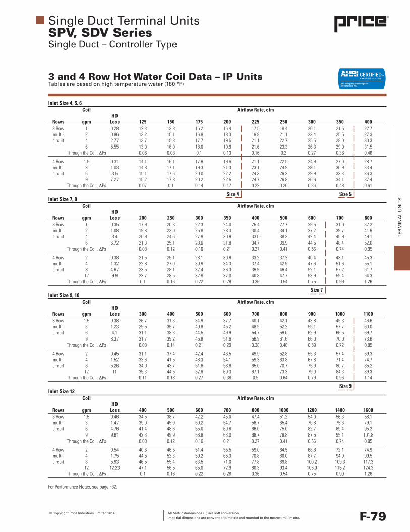
Inlet Size 4, 5, 6 Coil Airflow Rate, cfm HD Rows gpm Loss 125 150 175 200 225 250 300 350 400 3Row 1 0.28 12.3 13.8 15.2 16.4 17.5 18.4 20.1 21.5 22.7 multi- 2 0.86 13.2 15.1 16.8 18.3 19.8 21.1 23.4 25.5 27.3 circuit 4 2.77 13.7 15.8 17.7 19.5 21.1 22.7 25.5 28.0 30.3 6 5.55 13.9 16.0 18.0 19.9 21.6 23.3 26.3 29.0 31.5 Through the Coil, ∆Ps 0.06 0.08 0.1 0.13 0.16 0.2 0.27 0.36 0.46
4Row 1.5 0.31 14.1 16.1 17.9 19.6 21.1 22.5 24.9 27.0 28.7 multi- 3 1.03 14.8 17.1 19.3 21.3 23.1 24.9 28.1 30.9 33.4 circuit 6 3.5 15.1 17.6 20.0 22.2 24.3 26.3 29.9 33.3 36.3 9 7.27 15.2 17.8 20.2 22.5 24.7 26.8 30.6 34.1 37.4 Through the Coil, ∆Ps 0.07 0.1 0.14 0.17 0.22 0.26 0.36 0.48 0.61
Inlet Size 7, 8 Coil Airflow Rate, cfm HD Rows gpm Loss 200 250 300 350 400 500 600 700 800 3Row 1 0.35 17.9 20.3 22.3 24.0 25.4 27.7 29.5 31.0 32.2 multi- 2 1.08 19.8 23.0 25.8 28.3 30.4 34.1 37.2 39.7 41.9 circuit 4 3.4 20.9 24.6 27.9 30.9 33.6 38.3 42.4 45.9 49.1 6 6.72 21.3 25.1 28.6 31.8 34.7 39.9 44.5 48.4 52.0 Through the Coil, ∆Ps 0.08 0.12 0.16 0.21 0.27 0.41 0.56 0.74 0.95
4Row 2 0.38 21.5 25.1 28.1 30.8 33.2 37.2 40.4 43.1 45.3 multi- 4 1.32 22.8 27.0 30.9 34.3 37.4 42.9 47.6 51.6 55.1 circuit 8 4.67 23.5 28.1 32.4 36.3 39.9 46.4 52.1 57.2 61.7 12 9.9 23.7 28.5 32.9 37.0 40.8 47.7 53.9 59.4 64.3 Through the Coil, ∆Ps 0.1 0.16 0.22 0.28 0.36 0.54 0.75 0.99 1.26
Inlet Size 9, 10 Coil Airflow Rate, cfm HD Rows gpm Loss 300 400 500 600 700 800 900 1000 1100 3Row 1.5 0.38 26.7 31.3 34.9 37.7 40.1 42.1 43.8 45.3 46.6 multi- 3 1.23 29.5 35.7 40.8 45.2 48.9 52.2 55.1 57.7 60.0 circuit 6 4.1 31.1 38.3 44.5 49.9 54.7 59.0 62.9 66.5 69.7 9 8.37 31.7 39.2 45.8 51.6 56.9 61.6 66.0 70.0 73.6 Through the Coil, ∆Ps 0.08 0.14 0.21 0.29 0.38 0.48 0.59 0.72 0.85
4Row 2 0.45 31.1 37.4 42.4 46.5 49.9 52.8 55.3 57.4 59.3 multi- 4 1.52 33.6 41.5 48.3 54.1 59.3 63.8 67.8 71.4 74.7 circuit 8 5.26 34.9 43.7 51.6 58.6 65.0 70.7 75.9 80.7 85.2 12 11 35.3 44.5 52.8 60.3 67.1 73.3 79.0 84.3 89.3 Through the Coil, ∆Ps 0.11 0.18 0.27 0.38 0.5 0.64 0.79 0.96 1.14
Inlet Size 12 Coil Airflow Rate, cfm HD Rows gpm Loss 400 500 600 700 800 1000 1200 1400 1600 3Row 1.5 0.46 34.5 38.7 42.2 45.0 47.4 51.2 54.0 56.3 58.1 multi- 3 1.47 39.0 45.0 50.2 54.7 58.7 65.4 70.8 75.3 79.1 circuit 6 4.76 41.4 48.6 55.0 60.8 66.0 75.0 82.7 89.4 95.2 9 9.61 42.3 49.9 56.8 63.0 68.7 78.8 87.5 95.1 101.8 Through the Coil, ∆Ps 0.08 0.12 0.16 0.21 0.27 0.41 0.56 0.74 0.95
4Row 2 0.54 40.6 46.5 51.4 55.5 59.0 64.5 68.8 72.1 74.9 multi- 4 1.75 44.5 52.3 59.2 65.3 70.8 80.0 87.7 94.0 99.5 circuit 8 5.93 46.5 55.4 63.5 71.0 77.8 89.8 100.2 109.3 117.3 12 12.23 47.1 56.5 65.0 72.9 80.3 93.4 105.0 115.2 124.3 Through the Coil, ∆Ps 0.1 0.16 0.22 0.28 0.36 0.54 0.75 0.99 1.26
Single Duct Terminal UnitsSPV, SDV SeriesSingle Duct – Controller Type
3 and 4 Row Hot Water Coil Data – IP UnitsTables are based on high temperature water (180 °F)
ForPerformanceNotes,seepageF82.
Size 5Size 4
Size 7
Size 9
F-79

All Metric dimensions ( ) are soft conversion. © Copyright Price Industries Limited 2014. Imperial dimensions are converted to metric and rounded to the nearest millimetre.
TE
RM
INA
L U
NIT
S
Inlet Size 14 Coil Airflow Rate, cfm HD Rows gpm Loss 600 800 1000 1200 1400 1600 1800 2000 2200 3Row 2 0.54 50.2 57.9 63.6 68.0 71.5 74.4 76.8 78.8 80.6 multi- 4 1.76 57.5 68.8 78.0 85.6 92.1 97.7 102.5 106.8 110.5 circuit 8 5.93 61.5 75.2 87.0 97.2 106.1 114.1 121.2 127.7 133.6 12 12.23 62.9 77.5 90.3 101.5 111.6 120.6 128.8 136.2 143.1 Through the Coil, ∆Ps 0.08 0.14 0.21 0.29 0.38 0.48 0.59 0.72 0.85
4Row 3.5 0.74 61.5 73.5 83.0 90.7 97.0 102.3 106.9 110.8 114.2 multi- 7 2.68 66.9 82.4 95.6 107.0 116.9 125.6 133.3 140.2 146.4 circuit 14 9.92 69.6 87.2 102.8 116.6 129.1 140.3 150.6 160.0 168.6 21 21.51 70.5 88.9 105.3 120.1 133.6 145.9 157.2 167.6 177.3 Through the Coil, ∆Ps 0.11 0.18 0.27 0.38 0.5 0.64 0.79 0.96 1.14
Inlet Size 16 Coil Airflow Rate, cfm HD Rows gpm Loss 800 1000 1200 1400 1600 1800 2000 2200 2400 2600 2800 3Row 2.5 0.59 64.2 71.4 77.1 81.8 85.6 88.9 91.6 94.1 96.2 98.0 99.7 multi- 5 2.0 74.1 85.0 94.1 102.0 108.8 114.9 120.2 125.0 129.3 133.2 136.8 circuit 10 7.0 79.7 93.0 104.7 115.0 124.4 132.8 140.5 147.5 154.0 160.0 165.5 15 14.78 81.7 95.9 108.5 119.9 130.3 139.8 148.5 156.5 164.0 171 177.5 Through the Coil, ∆Ps 0.1 0.15 0.21 0.27 0.35 0.43 0.52 0.61 0.72 0.83 0.95
4Row 4.5 0.96 79.6 91.2 100.8 108.8 115.7 121.7 126.9 131.5 135.5 139.2 142.5 multi- 9 3.59 87.1 102.1 115.4 127.0 137.5 146.8 155.2 162.9 169.9 176.4 182.3 circuit 18 13.66 91 108.1 123.6 137.7 150.6 162.4 173.4 183.5 192.9 201.7 210.0 27 30.05 92.3 110.2 126.5 141.5 155.4 168.2 180.2 191.3 201.8 211.6 220.9 Through the Coil, ∆Ps 0.13 0.2 0.27 0.36 0.46 0.57 0.69 0.82 0.96 1.11 1.26
Inlet Size 24 x 16 Coil Airflow Rate, cfm HD Rows gpm Loss 1200 1500 2000 2500 3000 3500 4000 4500 5000 5500 6000 3Row 2.5 0.72 88.5 96.7 106.1 112.5 117.1 120.6 123.3 125.5 127.3 128.8 130.1 multi- 5 2.36 107.7 122.2 141.0 155.2 166.3 175.3 182.8 189.0 194.4 199.0 203.0 circuit 10 8.04 118.6 137.8 164.4 186.1 204.2 219.6 233.0 244.6 254.9 264.1 272.3 15 16.69 122.4 143.4 173.2 198.2 219.6 238.2 254.5 269.0 282.0 293.8 304.6 Through the Coil, ∆Ps 0.09 0.13 0.23 0.34 0.47 0.62 0.79 0.97 1.18 1.4 1.63
4Row 4.5 1.05 114.7 129.6 148.2 161.6 171.7 179.6 186.0 191.2 195.6 199.3 202.5 multi- 9 3.85 129.1 150.6 180.0 203.6 222.9 239.0 252.6 264.3 274.5 283.4 291.4 circuit 18 14.41 136.4 161.8 198.6 229.9 256.8 280.3 301.0 319.5 336.0 351.0 364.6 27 31.44 138.9 165.7 205.2 239.5 269.6 296.3 320.2 341.8 361.4 379.4 395.8 Through the Coil, ∆Ps 0.12 0.18 0.3 0.45 0.62 0.82 1.05 1.3 1.57 1.86 2.18
Single Duct Terminal UnitsSPV, SDV SeriesSingle Duct – Controller Type
3 and 4 Row Hot Water Coil Data – IP UnitsTables are based on high temperature water (180 °F)
Correction Factors – Hot Water Coils
Entering Water Temperature, °F
120 130 140 150 160 170 180 190 200 210 220
Entering 50 0.54 0.62 0.71 0.79 0.87 0.96 1.04 1.12 1.21 1.29 1.38
Air Temp °F 55 0.50 0.59 0.67 0.75 0.83 0.92 1.00 1.08 1.17 1.25 1.34
60 0.47 0.55 0.63 0.71 0.79 0.88 0.96 1.04 1.13 1.21 1.30
65 0.43 0.51 0.59 0.67 0.75 0.84 0.92 1.00 1.09 1.17 1.26
Performance Notes:1. Tabulated values are in MBH (thousands of Btu per hour).2. Tables are based on a temperature difference of 125 °F
(180°Fenteringwatertemperatureand55°Fenteringairtemperature). For other temperature differences, multiply MBH values by factors as listed above.
3. Minimum air and water flow values are based on ASHRAE recommendations for coil selections. For selections below these tabulated air or water values, please consult your local Price representative.
4. Do not select coils for a leaving air temperature above 120 °F.
5. HD (Head) loss is in ft of water.6. ∆Ps, is the pressure drop in in. of water across the coil.7. Airtemperaturerise=ATR,ATR(°F)=927xMBH/cfm8. Watertemperaturedrop=WTD,WTD(°F)=2.04xMBH/
gpm9. Values in tables are listed for 0 ft of altitude and no glycol
in the system.
10. For information outside the ranges used in the table, consult the current Price software or your Price representative for accurate coil information.
11. Heating coils used in this unit have performance rated and certified in accordance with the current edition of AHRI Standard 410.
12. Connections: 7/8 in. OD male solder.
F-80

© Copyright Price Industries Limited 2014. All Metric dimensions ( ) are soft conversion. Imperial dimensions are converted to metric and rounded to the nearest millimetre.
TE
RM
INA
L U
NIT
S
Single Duct Terminal UnitsSPV, SDV SeriesSingle Duct – Controller Type
3 and 4 Row Hot Water Coil Data – SI UnitsTables are based on high temperature water (82.2 °C)
Inlet Size 4, 5, 6 Coil Airflow Rate, L/s HD Rows L/s Loss 59 71 83 94 106 118 142 165 189 3 Row 0.06 0.82 3.6 4.1 4.5 4.9 5.2 5.5 6 6.4 6.7 multi- 0.13 2.58 3.9 4.5 5 5.4 5.9 6.2 6.9 7.6 8.1 circuit 0.25 8.27 4.1 4.7 5.2 5.8 6.3 6.7 7.6 8.3 9 0.38 16.53 4.1 4.7 5.3 5.9 6.4 6.9 7.8 8.6 9.3 Through the Coil, ∆Ps 15 20 25 32.5 40 50 67.5 90 115
4Row 0.09 0.92 4.2 4.8 5.3 5.8 6.3 6.7 7.4 8 8.5 multi- 0.19 3.06 4.4 5.1 5.7 6.3 6.9 7.4 8.3 9.2 9.9 circuit 0.38 10.44 4.5 5.2 5.9 6.6 7.2 7.8 8.9 9.9 10.8 0.57 21.67 4.5 5.3 6 6.7 7.3 7.9 9.1 10.1 11.1 Through the Coil, ∆Ps 17.5 25 35 42.5 55 65 90 120 152.5
Inlet Size 7, 8 Coil Airflow Rate, L/s HD Rows L/s Loss 94 118 142 165 189 236 283 330 378 3Row 0.06 1.05 5.3 6 6.6 7.1 7.5 8.2 8.8 9.2 9.5 multi- 0.13 3.23 5.9 6.8 7.6 8.4 9 10.1 11 11.8 12.4 circuit 0.25 10.14 6.2 7.3 8.3 9.1 9.9 11.4 12.6 13.6 14.5 0.38 20.02 6.3 7.4 8.5 9.4 10.3 11.8 13.2 14.4 15.4 Through the Coil, ∆Ps 20 30 40 52.5 67.5 102.5 140 185 237.5
4Row 0.13 1.14 6.4 7.4 8.3 9.1 9.8 11 12 12.8 13.4 multi- 0.25 3.93 6.8 8 9.1 10.2 11.1 12.7 14.1 15.3 16.3 circuit 0.5 13.91 7 8.3 9.6 10.8 11.8 13.8 15.4 16.9 18.3 0.76 29.5 7 8.4 9.8 11 12.1 14.1 16 17.6 19.1 Through the Coil, ∆Ps 25 40 55 70 90 135 187.5 247.5 315
Inlet Size 9, 10 Coil Airflow Rate, L/s HD Rows L/s Loss 142 189 236 283 330 378 425 472 519 3Row 0.09 1.14 7.9 9.3 10.3 11.2 11.9 12.5 13 13.4 13.8 multi- 0.19 3.67 8.8 10.6 12.1 13.4 14.5 15.5 16.3 17.1 17.8 circuit 0.38 12.21 9.2 11.3 13.2 14.8 16.2 17.5 18.6 19.7 20.7 0.57 24.95 9.4 11.6 13.6 15.3 16.9 18.3 19.5 20.7 21.8 Through the Coil, ∆Ps 20 35 52.5 72.5 95 120 147.5 180 212.5
4Row 0.13 1.35 9.2 11.1 12.6 13.8 14.8 15.6 16.4 17 17.6 multi- 0.25 4.54 10 12.3 14.3 16 17.6 18.9 20.1 21.2 22.1 circuit 0.5 15.68 10.3 13 15.3 17.4 19.2 20.9 22.5 23.9 25.2 0.76 32.78 10.5 13.2 15.6 17.9 19.9 21.7 23.4 25 26.4 Through the Coil, ∆Ps 27.5 45 67.5 95 125 160 197.5 240 285
Inlet Size 12 Coil Airflow Rate, L/s HD Rows L/s Loss 189 236 283 330 378 472 566 661 755 3Row 0.09 1.38 10.2 11.5 12.5 13.3 14 15.2 16 16.7 17.2 multi- 0.19 4.37 11.5 13.3 14.9 16.2 17.4 19.4 21 22.3 23.4 circuit 0.38 14.19 12.3 14.4 16.3 18 19.5 22.2 24.5 26.5 28.2 0.57 28.64 12.5 14.8 16.8 18.7 20.4 23.3 25.9 28.2 30.2 Through the Coil, ∆Ps 20 30 40 52.5 67.5 102.5 140 185 237.5
4Row 0.13 1.59 12 13.8 15.2 16.4 17.5 19.1 20.4 21.4 22.2 multi- 0.25 5.23 13.2 15.5 17.6 19.4 21 23.7 26 27.9 29.5 circuit 0.5 17.66 13.8 16.4 18.8 21 23 26.6 29.7 32.4 34.7 0.76 36.45 14 16.7 19.3 21.6 23.8 27.7 31.1 34.1 36.8 Through the Coil, ∆Ps 25 40 55 70 90 135 187.5 247.5 315
ForPerformanceNotes,seepageF84.
Size 5Size 4
Size 7
Size 9
F-81

All Metric dimensions ( ) are soft conversion. © Copyright Price Industries Limited 2014. Imperial dimensions are converted to metric and rounded to the nearest millimetre.
TE
RM
INA
L U
NIT
S
Correction Factors – Hot Water Coils
Entering Water Temperature, °C
49 54 60 66 71 77 82 88 93 99 104
Entering 10 0.54 0.62 0.71 0.79 0.87 0.96 1.04 1.12 1.21 1.29 1.38
Air Temp °C 13 0.50 0.59 0.67 0.75 0.83 0.92 1.00 1.08 1.17 1.25 1.34
16 0.47 0.55 0.63 0.71 0.79 0.88 0.96 1.04 1.13 1.21 1.30
18 0.43 0.51 0.59 0.67 0.75 0.84 0.92 1.00 1.09 1.17 1.26
Performance Notes:1. Tabulated values are in kW (kilowatts).2. Tables are based on a temperature difference of 69 °C
(82°Centeringwatertemperatureand13°Centeringairtemperature). For other temperature differences, multiply kW values by factors as listed above.
3. Minimum air and water flow values are based on ASHRAE recommendations for coil selections. For selections below these tabulated air or water values, please consult your local Price representative.
4. Do not select coils for a leaving air temperature above 49 °C.
5. HD (Head) loss is in kPa (kilopascals).6. ∆Ps, is the pressure drop in pascals across the coil.7. Airtemperaturerise=ATR,ATR(°C)=829xkW/L/s8. Water temperature drop =WTD,WTD (°C) = 0.224 x
kW/L/s
9. Values in tables are listed for 0 m of altitude and no glycol in the system.
10. For information outside the ranges used in the table, consult the current Price software or your Price representative for accurate coil information.
11. Heating coils used in this unit have performance rated and certified in accordance with the current edition of AHRI Standard 410.
12. Connections: 22 mm OD male solder.
Single Duct Terminal UnitsSPV, SDV SeriesSingle Duct – Controller Type
3 and 4 Row Hot Water Coil Data – SI UnitsTables are based on high temperature water (82.2 °C)
Inlet Size 14 Coil Airflow Rate, L/s HD Rows L/s Loss 283 378 472 566 661 755 850 944 1038 3Row 0.13 1.6 14.9 17.1 18.8 20.1 21.2 22.0 22.8 23.4 23.9 multi- 0.25 5.23 17.0 20.4 23.1 25.4 27.3 28.9 30.4 31.6 32.8 circuit 0.5 17.66 18.2 22.3 25.8 28.8 31.4 33.8 35.9 37.8 39.6 0.76 36.45 18.6 23.0 26.8 30.1 33.1 35.7 38.1 40.4 42.4 Through the Coil, ∆Ps 20.0 35.0 52.5 72.5 95.0 120 147.5 180.0 212.5
4Row 0.22 2.21 18.2 21.8 24.6 26.9 28.7 30.3 31.7 32.8 33.8 multi- 0.44 7.99 19.8 24.4 28.3 31.7 34.6 37.2 39.5 41.5 43.4 circuit 0.88 29.56 20.6 25.8 30.4 34.6 38.2 41.6 44.6 47.4 50.0 1.33 64.1 20.9 26.3 31.2 35.6 39.6 43.2 46.6 49.7 52.5 Through the Coil, ∆Ps 27.5 45.0 67.5 95.0 125.0 160.0 197.5 240.0 285
Inlet Size 16 Coil Airflow Rate, L/s HD Rows L/s Loss 378 472 566 661 755 850 944 1038 1133 1227 1321 3Row 0.16 1.75 19.0 21.2 22.8 24.2 25.4 26.3 27.2 27.9 28.5 29.0 29.5 multi- 0.32 5.95 22.0 25.2 27.9 30.2 32.3 34.0 35.6 37.0 38.3 39.5 40.5 circuit 0.63 20.87 23.6 27.6 31.0 34.1 36.8 39.3 41.6 43.7 45.6 47.4 49.0 0.95 44.04 24.2 28.4 32.2 35.5 38.6 41.4 44.0 46.4 48.6 50.7 52.6 Through the Coil, ∆Ps 25.0 37.5 52.5 67.5 87.5 107.5 130 152.5 180.0 207.5 237.5
4Row 0.28 2.85 23.6 27.0 29.9 32.3 34.3 36.1 37.6 39.0 40.2 41.2 42.2 multi- 0.57 10.69 25.8 30.3 34.2 37.6 40.7 43.5 46.0 48.3 50.3 52.3 54.0 circuit 1.14 40.71 27.0 32.0 36.6 40.8 44.6 48.1 51.4 54.4 57.2 59.8 62.2 1.7 89.54 27.4 32.7 37.5 41.9 46.0 49.8 53.4 56.7 59.8 62.7 65.5 Through the Coil, ∆Ps 32.5 50.0 67.5 90.0 115.0 142.5 172.5 205 240 277.5 315
Inlet Size 24 x 16 Coil Airflow Rate, L/s HD Rows L/s Loss 566 708 944 1180 1416 1652 1888 2124 2360 2596 2832 3Row 0.16 2.13 26.2 28.6 31.4 33.3 34.7 35.7 36.5 37.2 37.7 38.2 38.5 multi- 0.32 7.03 31.9 36.2 41.8 46.0 49.3 52.0 54.2 56 57.6 59.0 60.2 circuit 0.63 23.95 35.2 40.8 48.7 55.1 60.5 65.1 69.0 72.5 75.5 78.2 80.7 0.95 49.73 36.3 42.5 51.3 58.7 65.1 70.6 75.4 79.7 83.6 87.1 90.2 Through the Coil, ∆Ps 22.5 32.5 57.5 85.0 117.5 155 197.5 242.5 295.0 350.0 407.5
4Row 0.28 3.12 34.0 38.4 43.9 47.9 50.9 53.2 55.1 56.7 58.0 59.1 60.0 multi- 0.57 11.46 38.3 44.6 53.3 60.3 66.0 70.8 74.8 78.3 81.3 84.0 86.3 circuit 1.14 42.94 40.4 48 58.9 68.1 76.1 83.1 89.2 94.7 99.6 104.0 108.0 1.7 93.68 41.1 49.1 60.8 71.0 79.9 87.8 94.9 101.3 107.1 112.4 117.3 Through the Coil, ∆Ps 30.0 45.0 75.0 112.5 155.0 205.0 262.5 325.0 392.5 465.0 545.0
F-82