single and two-stage packaged geothermal heat … gi202 single and two-stage packaged geothermal...
TRANSCRIPT

12/06/2012 GI202
Single and Two-Stage Packaged Geothermal Heat Pump
Installation & Operating Instructions Models: TVA/TVT-***
Application Forced air Geo source installation Equipped for optional AUX EL strip heat (controller included) Dual Heat, LMC (load management control), etc. – add option TT-INT Tested to UL Standards 1995 and CSA Standards C22.2
3-Phase Models Also see and use GI102
Domestic Water Heater, Desuperheater Energy Star promotes the desuperheater and it is offered as an optional item for all TTHERM GEO™ heat pumps. Our exclusive GEO Logic™ control system optimizes the operation of a desuperheater, operating the systems only when there is adequate energy available to provide heat to the domestic hot water. However, to maximize the times the desuperheater aides in providing domestic hot water, a hot water preheat tank is suggested.
Note The GEO Logic control board has various required setup adjustments, see Field Setup section. TTHERM GEO heat pumps leave the factory setup to operate on an open loop. See Open Loop
Solenoid section.
DO NOT DESTROY THIS MANUAL. PLEASE READ CAREFULLY AND KEEP IN A SAFE PLACE FOR FUTURE REFERENCE BY A SERVICE TECHNICIAN.
Important information Model Number:____________________________ Serial Number:_____________________________ Installing Contractor:________________________

12/06/2012 GI202
Table of Contents
Introduction 1
Safety Considerations 2
TTHERM GEO Heat Pump Configurator (GC002) 3
Mechanical Specifications 4
Electrical Data 6
Duct System and Blower 7
Duct Sizing Chart 8
Product Dimensions 9
Installation Requirements 10
Mechanical Installation Overview 11
Mechanical Installation Source Water 12
Antifreeze 15
Open Loop Solenoid 16
Converting to Right Hand Return 18
Optional Electric Strip Heat (AUX EL) 19
Desuperheater, Domestic Hot Water (SWH) 20
Condensate Drain 22
Electrical Installation 23
GEO Logic Controller 24
Add-On Option and Accessories 25
Field Setup Overview 27
Dual Fuel/Utility Control 29
Operation Indicators 30
Power On, Start Up 35
Operational Tips 37
Preventative Maintenance 40
TVT & TVA Operating Conditions Tables 41
Troubleshooting 45
Drawing GR201 p1 – Water to Air Heating Mode – refrigerant circuit 48
Drawing GR201 p2 – Water to Air Cooling Mode – refrigerant circuit 49
Drawing UAW553 – Electrical Diagram 50
Warranty Information – GX002 51
12/06/2012 1 GI202
Introduction
Geothermal heat pumps are able to heat and cool spaces with efficiencies exceeding 350% by taking advantage of solar heat stored in the earth’s crust and the earth’s relatively stable temperatures. In the winter time, heat is moved from the earth into the home and concentrated using a refrigeration system. Since the heat already exists in the soil, the cost of operation of the geothermal heat pump is, in effect transportation cost for the free heat. In the summer, heat is removed from the home by reversing the refrigeration process and sending heat back out into the earth. A geothermal system consists of an earth source (either open loop or earth loop heat exchanger), a geothermal heat pump containing the refrigeration system and a ductwork system for delivering the conditioned air to the individual rooms. To learn more about geothermal heating, please visit our web site at www.tthermgeo.com This is a prewired package system with the necessary controls for various forced air heating applications. The GEO Logic control uses a standard, multi-wire heat pump room thermostat to initiate and terminate all heat/cool functions. There are various temperature sensors, pressure sensors, water flow switch, etc. which continuously monitor the heat pump system. The interaction of these sensing components, room thermostat requests, and the various heat pump refrigeration components plus optional AUX electric element heater are all controlled by an integrated microprocessor system (GEO Logic). The various setup conditions for this microprocessor based controller determine the application and geo product series. These setups are initially programmed by the factory, but special PC software and cable are available for reprogramming as required for controller replacement and/or other options which may apply to the specific installation. See Additional Equipment Concerns, Field Setup or Programming, Operation Indicators, User Instructions, Control Sequence, and Troubleshooting sections within this manual for further details on the GEO Logic control.
An optional T2-TT-INT-1 plug-in module is available to properly handle other applications with utility load control, backup furnace, backup boiler, dual fuel, etc. In addition to the compressor and AUX heater, proper operation of the forced blower and control of the external pumps are also operated with this optional module.
Moving and Storage Units should be stored in original packaging in a clean dry area. Store and move units in normal upright position. Do not stack units. Transport in vertical position only.
Initial Inspection Be certain to inspect all cartons and crates as units are received before signing the freight bill. Verify that all items received have no physical damage. Report any damages or shortages on the freight bill. The purchaser is responsible for filing the necessary claims with the carrier. Concealed or hidden damages not discovered until removing packaging must be reported to the carrier within 15 days of receipt.
Unit Location and Mounting Locate the unit in an indoor area where the ambient temperature will remain above 45°F [8°C]. TTHERM GEO provides 3 removable panels for ease of servicing; front (2), right and left bottom. This unit is zero clearance rated; however, allow enough room to remove panels for service and maintenance. We suggest setting the unit on a sound vibration pad, see accessories price sheet, part # E2-0122. Water supply should not be hard plumbed directly with copper or PVC pipe as this could transfer any vibration to living space. Consider using Hose Kit part # L3-0015B to minimize transferred vibration.
Please read and understand conditions associated with proper installation, unauthorized changes, and POWER ON procedures.
Warranty Statement See the last page of this manual for detailed limited warranty coverage explanation.

12/06/2012 2 GI202
Safety Considerations
WARNING BEFORE PERFORMING SERVICE OR MAINTENANCE OPERATIONS ON A SYSTEM, TURN OFF MAIN POWER SWITCHES TO THE INDOOR UNIT. IF APPLICABLE, TURN OFF THE ACCESSORY HEATER POWER SWITCH. ELECTRICAL SHOCK COULD CAUSE PERSONAL INJURY.
Installing and servicing heating and air conditioning equipment can be hazardous due to system pressure and electrical components. Only trained and qualified service personnel should install, repair or service heating and air conditioning equipment. Untrained personnel can perform the basic maintenance functions of cleaning coils and cleaning and replacing filters. All other operations should be performed by trained service personnel. When working on heating and air conditioning equipment, observe precautions in the literature, tags and labels attached to the unit and other safety precautions that may apply, such as the following safety measures: Follow all safety codes. Wear safety glasses and work gloves. Use a quenching cloth for brazing operations. Have a fire extinguisher available for all brazing operations.
Warnings, Cautions, and Notes Throughout this manual there are warnings, cautions and notes containing various levels of important information. Read all of these items carefully before performing any installation, servicing or troubleshooting of the system. Warnings are for any item which MUST be followed and failure to do so could result in serious injury or even death and/or serious damage to the equipment. Cautions relate to potentially hazardous situations or important practices which if ignored could cause minor to moderate injury or cause equipment damage or performance problems. Notes are used to indicate items of high importance but are not related to a hazardous situation.
10/12/2012 GC002
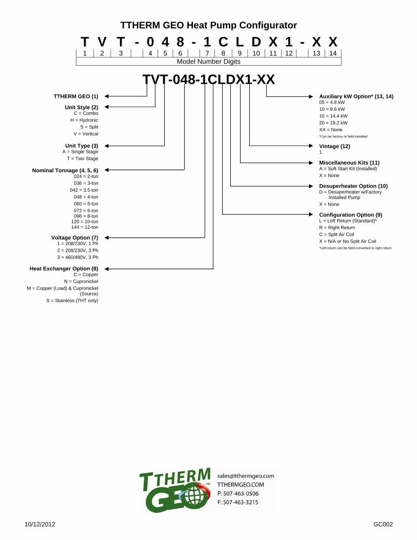
TTHERM GEO Heat Pump Configurator
TVT-048-1CLDX1-XX
TTHERM GEO (1)
Unit Style (2) C = Combo
H = Hydronic
S = Split
V = Vertical
Unit Type (3) A = Single Stage
T = Two Stage
Nominal Tonnage (4, 5, 6) 024 = 2-ton
036 = 3-ton
042 = 3.5-ton
048 = 4-ton
060 = 5-ton
072 = 6-ton 096 = 8-ton
120 = 10-ton 144 = 12-ton
Voltage Option (7) 1 = 208/230V, 1 Ph
2 = 208/230V, 3 Ph
3 = 460/480V, 3 Ph
Heat Exchanger Option (8) C = Copper
N = Cupronickel
M = Copper (Load) & Cupronickel (Source)
S = Stainless (THT only)
Auxiliary kW Option* (13, 14) 05 = 4.8 kW
10 = 9.6 kW
15 = 14.4 kW
20 = 19.2 kW
XX = None *Can be factory or field installed Vintage (12) 1 Miscellaneous Kits (11) A = Soft Start Kit (Installed)
X = None Desuperheater Option (10) D = Desuperheater w/Factory
Installed Pump
X = None Configuration Option (9) L = Left Return (Standard)*
R = Right Return
C = Split Air Coil
X = N/A or No Split Air Coil *Left return can be field converted to right return
T V T - 0 4 8 - 1 C L D X 1 - X X1 2 3 4 5 6 7 8 9 10 11 12 13 14
Model Number Digits
12/06/2012 4 GI202
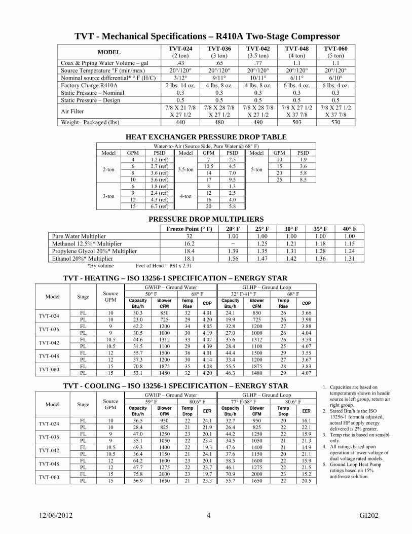
TVT - Mechanical Specifications – R410A Two-Stage Compressor
MODEL TVT-024
(2 ton) TVT-036
(3 ton) TVT-042 (3.5 ton)
TVT-048 (4 ton)
TVT-060 (5 ton)
Coax & Piping Water Volume – gal .43 .65 .77 1.1 1.1 Source Temperature °F (min/max) 20°/120° 20°/120° 20°/120° 20°/120° 20°/120° Nominal source differential* ° F (H/C) 3/12° 9/11° 10/11° 6/11° 6/10° Factory Charge R410A 2 lbs. 14 oz. 4 lbs. 8 oz. 4 lbs. 8 oz. 6 lbs. 4 oz. 6 lbs. 4 oz. Static Pressure – Nominal 0.3 0.3 0.3 0.3 0.3 Static Pressure – Design 0.5 0.5 0.5 0.5 0.5
Air Filter 7/8 X 21 7/8
X 27 1/2 7/8 X 28 7/8
X 27 1/2 7/8 X 28 7/8
X 27 1/2 7/8 X 27 1/2
X 37 7/8 7/8 X 27 1/2
X 37 7/8 Weight– Packaged (lbs) 440 480 490 503 530
HEAT EXCHANGER PRESSURE DROP TABLE
Water-to-Air (Source Side, Pure Water @ 68° F) Model GPM PSID Model GPM PSID Model GPM PSID
4 1.2 (ref) 7 2.5 10 1.9 6 2.7 (ref) 10.5 4.5 15 3.6 8 3.6 (ref) 14 7.0 20 5.8
2-ton
10 5.6 (ref)
3.5-ton
17 9.5
5-ton
25 8.5 6 1.8 (ref) 8 1.3 9 2.4 (ref) 12 2.5
12 4.3 (ref) 16 4.0 3-ton
15 6.7 (ref)
4-ton
20 5.8
PRESSURE DROP MULTIPLIERS
Freeze Point (° F) 20° F 25° F 30° F 35° F 40° F Pure Water Multiplier 32 1.00 1.00 1.00 1.00 1.00 Methanol 12.5%* Multiplier 16.2 − 1.25 1.21 1.18 1.15 Propylene Glycol 20%* Multiplier 18.4 1.39 1.35 1.31 1.28 1.24 Ethanol 20%* Multiplier 18.1 1.56 1.47 1.42 1.36 1.31
*By volume Feet of Head = PSI x 2.31
TVT - HEATING – ISO 13256-1 SPECIFICATION – ENERGY STAR
GWHP – Ground Water GLHP – Ground Loop 50° F 68° F 32° F/41° F 68° F Model Stage
Source GPM Capacity
Btu/h Blower
CFM Temp Rise
COP Capacity
Btu/h Blower
CFM Temp Rise
COP
FL 10 30.3 850 32 4.01 24.1 850 26 3.66 TVT-024
PL 10 23.0 725 29 4.20 19.9 725 26 3.98 FL 9 42.2 1200 34 4.05 32.8 1200 27 3.88
TVT-036 PL 9 30.5 1000 30 4.19 27.0 1000 26 4.04 FL 10.5 44.6 1312 33 4.07 35.6 1312 26 3.59
TVT-042 PL 10.5 31.5 1100 29 4.39 28.4 1100 25 4.07 FL 12 55.7 1500 36 4.01 44.4 1500 29 3.55
TVT-048 PL 12 37.3 1200 30 4.14 33.4 1200 27 3.67 FL 15 70.8 1875 35 4.08 55.5 1875 28 3.83
TVT-060 PL 15 53.1 1480 32 4.20 46.3 1480 29 4.07
TVT - COOLING – ISO 13256-1 SPECIFICATION – ENERGY STAR
GWHP – Ground Water GLHP – Ground Loop 59° F 80.6° F 77° F/68° F 80.6° F Model Stage
Source GPM Capacity
Btu/h Blower
CFM Temp Drop
EER Capacity
Btu/h Blower
CFM Temp Drop
EER
FL 10 36.5 950 22 24.1 32.7 950 20 16.1 TVT-024
PL 10 28.4 825 21 21.9 26.4 825 22 22.1 FL 9 47.0 1250 23 20.1 44.2 1250 22 15.9
TVT-036 PL 9 35.1 1050 22 23.4 34.5 1050 21 21.3 FL 10.5 49.3 1400 22 19.3 47.6 1400 21 14.9
TVT-042 PL 10.5 36.4 1150 21 24.1 37.6 1150 20 21.1 FL 12 64.2 1600 23 20.1 58.3 1600 22 15.9
TVT-048 PL 12 47.7 1275 22 23.7 46.1 1275 22 21.5 FL 15 75.8 2000 23 19.7 70.9 2000 23 15.2
TVT-060 PL 15 56.9 1650 21 23.3 55.7 1650 22 20.5
1. Capacities are based on temperatures shown in headinsource is left group, return air right group.
2. Stated Btu/h is the ISO 13256-1 formula adjusted, actual HP supply energy delivered is 2% greater.
3. Temp rise is based on sensibleonly.
4. All ratings based upon operation at lower voltage of dual voltage rated models.
5. Ground Loop Heat Pump ratings based on 15% antifreeze solution.

12/06/2012 5 GI202
TVA – Mechanical Specifications – R410A Single Stage Compressor
MODEL TVA-036
(3 ton) TVA-048
(4 ton) TVA-060
(5 ton) Coax & Piping Water Volume – gal .65 1.1 1.1 Source Temperature °F (min/max) 20°/120° 20°/120° 20°/120° Nominal source differential* °F (H/C) 9/11° 6/11° 6/10° Factory Charge R410A 4 lbs. 8 oz. 6 lbs. 4 oz. 6 lbs. 4 oz. Static Pressure – Nominal 0.3 0.3 0.3 Static Pressure – Design 0.5 0.5 0.5
Air Filter 7/8 X 28 7/8
X 27 1/2 7/8 X 27 1/2
X 37 7/8 7/8 X 27 1/2
X 37 7/8 Weight– Packaged (lbs) 460 480 503
HEAT EXCHANGER PRESSURE DROP TABLE
Water-to-Air (Source Side, Pure Water @ 68° F) Model GPM PSID Model GPM PSID Model GPM PSID
6 1.8 (ref) 8 1.3 10 1.9 9 2.4 (ref) 12 2.5 15 3.6
12 4.3 (ref) 16 4.0 20 5.8 3-ton
15 6.7 (ref)
4-ton
20 5.8
5-ton
25 8.5
PRESSURE DROP MULTIPLIERS
Freeze Point (° F) 20° F 25° F 30° F 35° F 40° F Pure Water Multiplier 32 1.00 1.00 1.00 1.00 1.00 Methanol 12.5%* Multiplier 16.2 − 1.25 1.21 1.18 1.15 Propylene Glycol 20%* Multiplier 18.4 1.39 1.35 1.31 1.28 1.24 Ethanol 20%* Multiplier 18.1 1.56 1.47 1.42 1.36 1.31
*By volume Feet of Head = PSI x 2.31
TVA – HEATING – ISO 13256-1 SPECIFICATION – ENERGY STAR
GWHP – Ground Water GLHP – Ground Loop 50° F 68° F 32° F 68° F Model
Source GPM Capacity
Btu/h Blower
CFM Temp Rise
COP Capacity
Btu/h Blower
CFM Temp Rise
COP
TVA-036 10 42.6 1200 34 4.28 32.7 1200 27 3.66 TVA-048 13 57.3 1500 35 4.10 45.2 1500 27 3.60 TVA-060 15 63.5 1875 35 4.10 50.7 1875 28 3.60
TVA – COOLING – ISO 13256-1 SPECIFICATION – ENERGY STAR
GWHP – Ground Water GLHP – Ground Loop 59° F 80.6° F 77° F 80.6° F Model
Source GPM Capacity
Btu/h Blower
CFM Temp Drop
EER Capacity
Btu/h Blower
CFM Temp Drop
EER
TVA-036 10 42.0 1250 23 22.9 38.1 1250 21 17.5 TVA-048 12 55.4 1600 24 22.2 52.6 1600 23 17.1 TVA-060 15 65.0 2000 23 21.4 63.8 2000 23 17.1
1. Capacities are based on temperatures shown in heading, source is left group, return air is right group. 2. Stated Btu/h is the ISO 13256-1 formula adjusted, actual HP supply energy delivered is 2% greater. 3. Temp rise is based on sensible only. 4. All ratings based upon operation at lower voltage of dual voltage rated models. 5. Ground Loop Heat Pump ratings based on 15% antifreeze solution.

12/06/2012 6 GI202
TVT - Electrical Data – Single Phase
Voltage Compressor Blower Desup. Pump
Loop Pump (Ext)
Total Min. Model
(60 Hz) RLA LRA FLA FLA FLA FLA Ampac.
Max. Fuse/ HAC
R
TVT-024 208/230-1 13.1 73 4.5 .15 4.4 23.1 25.4 30 TVT-036 208/230-1 17.9 96 6.1 .15 4.4 28.6 33.0 50 TVT-042 208/230-1 21.2 104.0 6.1 .15 4.4 31.9 37.2 50 TVT-048 208/230-1 27.1 152.9 6.1 .15 4.4 37.8 44.4 70 TVT-060 208/230-1 29.7 179.2 7.3 .15 4.4 41.6 49.0 70
TVT - Electrical Data – Three-Phase
Voltage Compressor Blower Desup. Pump
Loop Pump (Ext)
Total Min. Model
(60 Hz) RLA LRA FLA FLA FLA FLA Ampac.
Max. Fuse/ HAC
R
TVT-024 NOT AVAILABLE TVT-036 200/230-3 14.2 88 6.1 .15 4.4 24.9 28.3 40 TVT-042 200/230-3 14.0 83.1 6.1 .15 4.4 24.7 25.8 40 TVT-048 200/230-3 16.5 110.0 6.1 .15 4.4 28.3 32.5 50 TVT-060 NOT AVAILABLE
TVA – Electrical Data – Single Phase
Voltage Compressor Blower Desup. Pump
Loop Pump (Ext)
Total Min. Model
(60 Hz) RLA LRA FLA FLA FLA FLA Ampac.
Max. Fuse/
HACR
TVA-036 208/230-1 17.9 112.0 6.1 .15 4.4 28.6 33.0 50 TVA-048 208/230-1 26.4 134 6.1 .15 4.4 37.5 43.5 70 TVA-060 208/230-1 28.3 178.0 7.3 .15 4.4 40.2 47.2 70
TVA – Electrical Data – Three-Phase
Voltage Compressor Blower Desup. Pump
Loop Pump (Ext)
Total Min. Model
(60 Hz) RLA LRA FLA FLA FLA FLA Ampac.
Max. Fuse/
HACR
TVA-036 200/230-3 13.5 88 6.1 .15 4.4 24.2 27.5 40 TVA-048 200/230-3 17.6 123 6.1 .15 4.4 31.1 36.2 50 TVA-060 200/230-3 20.5 155 7.3 .15 4.4 32.4 37.5 50

12/06/2012 7 GI202
Duct System and Blower
Metal ductwork should be used, and flexible connectors are required for supply and return air duct connections. All TVA & TVT THERM GEO units have flanges for connecting your supply plenum and return ductwork. If the duct system is installed in an uninsulated space, the metal ductwork should be insulated on the outside to prevent heat loss, absorb noise, and prevent condensation during cooling. If the TTHERM GEO is connected to existing ductwork, the ductwork must have the capacity to handle the air volume required to unload the heat pump. Undersized ductwork will cause noisy operation due to high air velocity, and poor operating efficiencies. Check the Duct Sizing Chart provided. The TTHERM GEO heat pumps use a variable speed ECM blower motor. The GEO Logic controller determines the speed of the motor based on mode and operation sequence. The blower speed can be fine-tuned to each installation with the tweak switches described below. The blower will not operate properly if ductwork is not attached. The ductwork provides static pressure to give the blower motor a load to work against. All blower compartment covers must be in place for the heat pump to operate correctly.
TVT - Blower CFM – Two Stage Compressor
Model G Cool Y Heat Y Cool Y2 Heat Y2 Cool Y 2 Heat + W2 E
TVT – 024 390 640 735 850 980 980 680 TVT – 036 515 900 965 1200 1290 1380 960 TVT – 042 575 985 1080 1310 1440 1500 1050 TVT – 048 660 1125 1235 1500 1650 1725 1200 TVT – 060 825 1400 1545 1875 2060 2160 1500
CFM Rounded Y2 can be field fine-tuned or tweaked with a 4 position switch. The 4 positions are 0%, -6%, +6%, +12% G can be field fine-tuned or tweaked with a 4position switch. The 4 positions are 0%, -6%, +6%, +12% See figure 8 for location of 4 position switch
TVA - Blower CFM – Single Stage Compressor
Model G Cool Y Heat Y Cool Y Heat + W2 E
TVA - 036 515 1200 1290 1380 960 TVA - 048 660 1500 1650 1725 1200 TVA - 060 825 1875 2060 2160 1500
CFM Rounded Y can be field fine-tuned or tweaked with a 4 position switch. The 4 positions are 0%, -6%, +6%, +12% G can be field fine-tuned or tweaked with a 4position switch. The 4 positions are 0%, -6%, +6%, +12% See figure 8 for location of 4 position switch The “Y” tweak switch is the 2nd switch below the 10 pin thermostat socket. The “G” tweak switch is the 3rd switch below the 10 pin thermostat socket. Be very sure the tweak switches are set in their position indents.

12/06/2012 8 GI202
Duct Sizing Chart
Acceptable Branch Duct Sizes Acceptable Main or Trunk Duct Sizes CFM ROUND Rectangular Round Rectangular
100 6” 4x8, 4x6 150 7” 4x10, 5x8, 6x6 200 8” 5x10, 6/8,4x14,7x7 250 9” 6x10, 8x8, 4x16 300 10” 6x14, 8x10, 7x12 350 10” 6x20, 6x16. 9x10 400 12” 6x18, 10x10, 9x12 10” 4x20, 7x10, 6x12, 8x9 450 12” 6x20, 8x14, 9x12, 10x11 10” 5x20, 6x16, 9x10, 8x12 500 10” 10x10,6x8, 8x12, 7x14 600 12” 6x10, 7x18, 8x16, 10x12 800 12” 8x18, 9x15, 10x14, 12x12
1000 14” 10x18, 12x14, 8x24 1200 16” 10x20, 12x18, 14x15 1400 16” 10x25, 12x20, 14x18, 15x16 1600 18” 10x30, 15x18, 14x20 1800 20” 10x35, 15,20, 16x19, 12x30, 14x25 2000 20” 10x40, 12x30, 15x25, 18x20 2200 22” 10x40, 15x25, 20x20 2400 22” 12x40, 16x25, 20x20
Table calculated for 0.05 to 0.10 inches of water friction per 100’ of duct. At these duct design conditions, along with the pressure drop through the filter, the total design external static is 0.20 inches of water.

12/06/2012 9 GI202
Product Dimensions

12/06/2012 10 GI202
Installation Requirements 1. All installation work must be performed by trained, qualified contractors or technicians. TTHERM GEO
sponsors installation and service schools to assist the installer. Contact TTHERM GEO at [email protected] for upcoming dealer training events.
WARNING ALL ELECTRICAL WIRING MUST BE IN ACCORDANCE WITH NATIONAL ELECTRIC CODE AND LOCAL ELECTRIC CODES, ORDINANCES, AND REGULATIONS.
WARNING OBSERVE ELECTRIC POLARITY AND WIRING COLORS. FAILURE TO OBSERVE COULD CAUSE ELECTRIC SHOCK AND/OR DAMAGE TO THE EQUIPMENT.
CAUTION This unit can only be used for its intended purpose as described in this manual. Any internal wiring changes, modifications to the circuit board, modifications or bypass of any controls, or installation practices not according to the details of this manual will void the product warranty, the safety certification label, and manufacturer product liability. TTHERM GEO cannot be held responsible for field modifications, incorrect installations, and conditions which may bypass or compromise the built-in safety features and controls.
2. If this is a Dual Fuel system, this product relates only to the addition to the furnace ducting system external
to the gas or oil force air furnace. The owner/installer assumes all responsibility and/or liability associated with any needed installation of the gas/oil furnace, fuel system, flue, chimney, etc. Any instructions or comments made within this manual (or factory phone assistance) relating to the gas/oil furnace are provided as comments of assistance and “helps” only.
CAUTION This unit shall not be operated (either heating section or blower) until the interior of the structure is completed and cleaned. This also means all duct work must be complete with filter, etc. Manufacturer’s warranty is void if this unit is operated during structure construction.
CAUTION Hazards or unsafe practices could result in property damage, product damage, severe personal injury and/or death.
3. All removed or discharged refrigerant must be recovered In accordance with local and federal statutes.
Should a compressor need replacing, the compressor oil is to remain with the compressor. Refrigerant lines on the compressor must be capped during service.
4. Remember, safety is the installer’s responsibility and the installer must know this product well enough to
instruct the end user on its safe use.
At TTHERM GEO the safety of the installer and the end user is of highest priority. Remember, safety is the installer’s responsibility and the installer must know this product well enough to instruct the end user on its safe use. Professional installers should be trained and experienced in the areas of handling electrical components, sheet metal products, and material handling processes.
12/06/2012 11 GI202
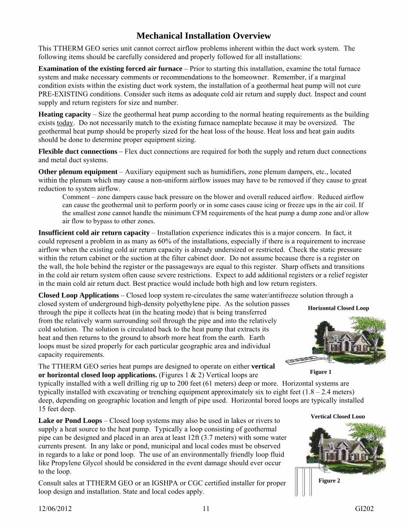
Figure 1
Horizontal Closed Loop
Mechanical Installation Overview
This TTHERM GEO series unit cannot correct airflow problems inherent within the duct work system. The following items should be carefully considered and properly followed for all installations:
Examination of the existing forced air furnace – Prior to starting this installation, examine the total furnace system and make necessary comments or recommendations to the homeowner. Remember, if a marginal condition exists within the existing duct work system, the installation of a geothermal heat pump will not cure PRE-EXISTING conditions. Consider such items as adequate cold air return and supply duct. Inspect and count supply and return registers for size and number.
Heating capacity – Size the geothermal heat pump according to the normal heating requirements as the building exists today. Do not necessarily match to the existing furnace nameplate because it may be oversized. The geothermal heat pump should be properly sized for the heat loss of the house. Heat loss and heat gain audits should be done to determine proper equipment sizing.
Flexible duct connections – Flex duct connections are required for both the supply and return duct connections and metal duct systems.
Other plenum equipment – Auxiliary equipment such as humidifiers, zone plenum dampers, etc., located within the plenum which may cause a non-uniform airflow issues may have to be removed if they cause to great reduction to system airflow.
Comment – zone dampers cause back pressure on the blower and overall reduced airflow. Reduced airflow can cause the geothermal unit to perform poorly or in some cases cause icing or freeze ups in the air coil. If the smallest zone cannot handle the minimum CFM requirements of the heat pump a dump zone and/or allow air flow to bypass to other zones.
Insufficient cold air return capacity – Installation experience indicates this is a major concern. In fact, it could represent a problem in as many as 60% of the installations, especially if there is a requirement to increase airflow when the existing cold air return capacity is already undersized or restricted. Check the static pressure within the return cabinet or the suction at the filter cabinet door. Do not assume because there is a register on the wall, the hole behind the register or the passageways are equal to this register. Sharp offsets and transitions in the cold air return system often cause severe restrictions. Expect to add additional registers or a relief register in the main cold air return duct. Best practice would include both high and low return registers.
Closed Loop Applications – Closed loop system re-circulates the same water/antifreeze solution through a closed system of underground high-density polyethylene pipe. As the solution passes through the pipe it collects heat (in the heating mode) that is being transferred from the relatively warm surrounding soil through the pipe and into the relatively cold solution. The solution is circulated back to the heat pump that extracts its heat and then returns to the ground to absorb more heat from the earth. Earth loops must be sized properly for each particular geographic area and individual capacity requirements.
The TTHERM GEO series heat pumps are designed to operate on either vertical or horizontal closed loop applications. (Figures 1 & 2) Vertical loops are typically installed with a well drilling rig up to 200 feet (61 meters) deep or more. Horizontal systems are typically installed with excavating or trenching equipment approximately six to eight feet (1.8 – 2.4 meters) deep, depending on geographic location and length of pipe used. Horizontal bored loops are typically installed 15 feet deep.
Lake or Pond Loops – Closed loop systems may also be used in lakes or rivers to supply a heat source to the heat pump. Typically a loop consisting of geothermal pipe can be designed and placed in an area at least 12ft (3.7 meters) with some water currents present. In any lake or pond, municipal and local codes must be observed in regards to a lake or pond loop. The use of an environmentally friendly loop fluid like Propylene Glycol should be considered in the event damage should ever occur to the loop.
Consult sales at TTHERM GEO or an IGSHPA or CGC certified installer for proper loop design and installation. State and local codes apply.
Figure 2
Vertical Closed Loop

12/06/2012 12 GI202
Figure 3
P/T Adapter
Mechanical Installation Source Water
WARNING LOOP DESIGN IS EXTREMELY IMPORTANT FOR PROPER HEAT PUMP OPERATION. INCORRECT LOOP DESIGN WILL REDUCE HEAT PUMP EFFICIENCY, CAUSE POOR PERFORMANCE OR MAY RENDER THE SYSTEM UNUSABLE. IF YOU LACK EXPERIENCE DESIGNING LOOP FIELDS, CONTACT AN IGSHPA OR CGC CERTIFIED GEOTHERMAL LOOP CONTRACTOR FOR PROPER INSTALLATIONS.
Water Connections General The following pages outline typical piping arrangements for the most common source water connection options, as well as flushing and filling procedures and antifreeze requirements for closed loop systems. TTHERM GEO recommends hose kits for the source water connection points at the heat pump. This will provide a flexible connection to reduce and isolate vibrations transmitting from the compressor into other parts of the system. Hose kits also provide P/T ports for monitoring pressure and temperature (see below).
Note TTHERM GEO heat pumps are factory set for open loop. J11 must be removed for proper operation on an antifreeze protected closed loop. See figure on page 26 for the location of J11.
Once closed loops are completed, they must be pressure tested to at least 60 PSI to ensure integrity. Once pressure is tested, loop must be purged of all foreign debris and filled with fluid. All air must be removed at this time by flushing the system. (Page 11, Table 2) shows approximate fluid volumes. Pressure/Temperature (P/T) plugs – Should be installed in the adaptor elbow on the entering and leaving water line of the heat pump on a closed system. (Figure 3) A thermometer can be inserted into the P/T ports to check entering and leaving water temperatures. A pressure gauge can also be inserted into these P/T ports to determine the pressure differential between the entering and leaving water. This pressure differential can then be compared to the engineering specifications data to determine the flow rate of the system. Non Pressurized Loops require an
air separator/stand pipe to eliminate air and to hold enough fluid to compensate for the expansion and contraction of the loop pipe and fluid. Purge and fill valves should be placed between the loop manifold valves and the insulated pump pack. A Flow Meter is an important part of the system. It provides a visual indicator of loop flow in GPM. A flow meter can be installed on either side of the pump pack, but must be installed per manufacture recommendations so it reads accurately. Non Pressurized Loops require an air separator/stand pipe to eliminate air and to hold enough fluid to compensate for the expansion and contraction of the loop pipe and fluid. Purge and fill valves should be placed between the loop manifold valves and the insulated pump pack. See figure 4.
12/06/2012 13 GI202
Pressurized Loops do not require an air separator. They require purge and fill ports between the loop manifold valves and the insulated pump pack. After purging a pressurized loop, it should maintain 45 to 60 psi static pressure. The Geothermal Loop Pipe stretches under pressure so may need to be pressurized above the desired pressure several times to achieve the recommended static pressure. Pressurized loops must maintain enough static pressure to compensate for the expansion and contraction of the loop pipe and fluid. Loop Pump Selection – Select a loop circulation pump based upon the GPM required and total system pressure drop. See specification, page 4. Geothermal heat pump Btu/h capacity and efficiency are directly related to the GPM flow through the unit. Vibration pad – We recommend setting the unit on a sound vibration pad, available from most distributors or accessories price sheet – E2-0122. Water quality – Models with standard copper heat exchanger coils require the installer to evaluate water quality and meet minimum water properties. pH < 7.5 Calcium hardness < 100 PPM Iron fouling < 0.2 PPM (Ferrous)
< 0.5 PPM of oxygen Hydrogen sulfide (H2S) < 0.5 PPM Chloride levels < 20 PPM Erosion/clogging < 10 PPM, particles Filter, if required < 800 micron size
Softened water is recommended along with 2 oz of common house chlorine bleach for every 10 gallons of water.

12/06/2012 14 GI202
Figure 4 – Non-Pressurized Closed Loop with Flow Center – Typical piping diagram.
Figure 5 – Pressurized Closed Loop with Flow Center – Typical piping arrangement.

12/06/2012 15 GI202
Antifreeze When considering the earth loop solution, water quality is very important. TTHERM GEO recommends a minimum of soft water (not well water) treated with 2 oz. of household chlorine bleach for each 10 gallons of total volume. TTHERM GEO’s recommended antifreeze concentration is 22% which will yield a freeze protection of 18° F. This concentration of glycol requires additional additives to protect the system. TTHERM GEO recommends Enviro-Guard HD propylene glycol for this reason. Over antifreeze protecting a loop field decreases pumping capacity when the loop gets cold and reduces thermal transfer. Under protecting a loop field will cause the THERM GEO heat pump to take action protecting itself from damage. This action will result in a loss of geothermal capacity, and AUX heat may be required to maintain the temperature in the home.
Table 2 – Approximate Fluid Volume (gal) per 100ft Pipe Size Volume Pipe Size Volume
¾” IPS SDR 11 3.02 1” 4.1 1” IPS SDR 11 4.73
Rubber Hose 1.25” 6.4
1-1/4” IPS SDR 11 7.55 1” 4.5 1-1/2” IPS SDR 11 9.93 1.25” 6.8
Polyethylene
2” IPS SDR 11 15.36
Copper Type M
1.5” 9.5
WARNING PREVENTING FREEZE-UP IS INSTALLER/USER RESPONSIBILITY. DAMAGE CAUSED BY FREEZE-UP IS NOT COVERED BY WARRANTY.
CAUTION Softened water is recommended along with 2 oz of common household chlorine bleach for every 10 gallons of water.
WARNING NOT ALL GLYCOLS PROVIDE THE SAME LEVEL OF CONCENTRATION. MOST GLYCOLS DO NOT CONTAIN ENOUGH INHIBITORS FOR THE RECOMMENDED CONCENTRATION LEVELS.FOR GEOTHERMAL SYSTEMS..
Open Loop– An open system gets its name from the open discharge of water after it has been used by the heat pump. A well pump and well must be available that can supply all of the water requirements of the heat pump along with any other water requirements drawing off that same well. The well must be capable of supplying the heat pumps required flow rated for up to 24 hours per day for the coldest winter day. Figure 6 shows the necessary components for water piping of an open system. First a bladder type pressure tank with a “draw down” of at least 1-1/2 to 2 times the well pump capacity must be installed on the supply side of the heat pump to prevent short cycling the well pump. Constant pressure well pumps need to deliver the GPM flow rate of the TTHERM GEO heat pump and other possible consecutive demands. Shut off valves and boiler drains on the entering and leaving water lines are necessary for future maintenance. A screen strainer is placed on the supply line with a mesh size of 40 to 60 and enough surface area to allow for particle buildup between cleanings. Hose kits are installed between the heat pump and ridged plumbing to reduce vibration transfer. Hose kits have pressure temperature (P/T) plugs placed in the supply and discharge hydrant elbows so that

12/06/2012 16 GI202
thermometers or pressure gauges can be inserted into the water stream. On the well water discharge side of the heat pump a flow meter is installed to provide a visual indicator of open loop flow in GPM. The water solenoid valve must be installed to control water flow through the unit. After the water solenoid a flow control valve is installed to limit maximum flow through the heat pump. The ball valve installed in the leaving water line can be used to create a small amount of back pressure to quiet the flow control valve if needed. Discharge water temperature should not drop below 39° at any time during the units operation. Remove handle on the entering and leaving water ball valves to prevent accidental change of flow. . The solenoid valve is then wired to two leads (brown/yellow and gray) provided. This valve will open when the unit is running and close when the unit stops. The visual flow meter will allow visual inspection of the flow requirements, and can be useful in determining when maintenance is required. Schedule 40 PVC piping, copper tubing, polyethylene or rubber hose can be used for supply and discharge water lines. Make sure line sizes are large enough to supply the required flow with a reasonable pressure drop (generally 1.00” diameter). Water discharge is generally made to a drain field, stream, pond, surface discharge, tile line, or storm sewer. Solenoid Valve Wiring (for Open Loop Systems) Inside the cabinet, tie-wrapped to the OUT water pipe, are two leads (brn/yel and gray) for direct connection to a 24VAC solenoid.
CAUTION Using a drain field requires soil conditions and adequate sizing to assure rapid percolation or the required flow rates will not be achieved. Consult local codes and ordinances to assure compliance. Do not discharge water to a septic system. The heat pump should never be operated with flow rates (GPM) less than specified. Discharge water should never be lower than 39° F. Operation of the unit with less than required flow rate or no flow may result in freezing water in the water to refrigerant heat exchanger. This will cause the unit to shut down on low-pressure lockout. If the unit locks out Low pressure, verify that the unit has the required flow and reset the unit by shutting off power to the unit for one minute. Do not continually reset the unit; if the unit locks out more than once call your service professional. Continued reset of the unit can freeze water inside the water coil to the point of rupturing the water coil (no warranty for freeze ruptured coils).

12/06/2012 17 GI202
Figure 6: Open Loop – Typical piping diagram.
Note TTHERM GEO heat pumps are factory set for open loop operation.
Open Loop Operation – TTHERM GEO heat pumps are factory set for open loop operation. Open or Closed loop operation is set with jumper J11 on the left side of the GEO Logic controller. The jumper must be in place on J11 if the unit is operated on an open loop. The GEO Logic controller protects the heat exchanger from freezing by causing the compressor to shut down when the leaving water temperature reaches 39° F. The compressor will remain off for 2 Anti-Cycle-Delay’s, and the EARTH LOOP FLOW/ SOURCE WATER LIMIT & HP STAGE 1 LED’s will pulse, while the water runs and warms up. The compressor will then restart again providing heat until the LWT again reaches 39° F. If this routine continues the heat pump may not be able to maintain the temperature in the house and the backup heat will come on. Possible causes would include:
1. Supply water filter that needs cleaning 2. Inadequate water supply 3. Water discharge line that is plugging up 4. Entering water temperature less than 50 degrees
Water Coil Maintenance – Water quality is a major concern for open systems. Problems can occur from scaling, particle buildup, suspended solids, corrosion, pH levels outside the 7-9 ranges, or biological growth. A cupronickel heat exchanger is recommended for open loop applications. If poor water quality is known to exist in your area a closed loop system may be the best alternative. Water coil cleaning on an open loop system may be necessary on a regular basis.
12/06/2012 18 GI202
Converting to Right Hand Return
Converting to Right Hand Return – One of the unique features of your TTHERM GEO series heat pump is the ability to quickly and easily convert the unit from the factory-shipped left-hand return air configuration to a configuration where return air enters the unit from the right-hand side. This is accomplished by moving the access doors and GEO Logic control box from the front of the cabinet to the rear of the cabinet and rotating the heat pump 180°.
1. First, make certain that power is disconnected from the heat pump and remove the front, rear, and
side panels opposite of the air coil and filter.
2. Disconnect the two blower motor wire harnesses at the blower motor.
3. Using a Phillips screwdriver, remove the control box and hinged access doors. The attached wiring harnesses are sufficiently long enough to allow for the relocation of the control box and door without rewiring these components. Be sure the refrigerant manifold distribution lines do not rest against the u-bends of the coil or the relocated control box.
4. Relocate and secure the control box and doors on the opposite side of the cabinet.
5. If you are not installing electric strip heat reattach the blower motor cables, front, rear and side panels. Your TTHERM GEO has now been converted to right-hand return.
6. If you are installing an optional electric strip heat module (KN-XX-T) observe the steps below.
Step #1 Remove (4) blower retaining screws and the retaining bracket keeping the blower from sliding. Remove blower assembly from the cabinet.
Step #2 Remove the electrical box and heating element/s from the electric heater’s plenum. See Auxiliary Strip Heat Installation Instructions.
Step #3 Invert the heater’s electrical box and reinstall in the heater’s plenum. This will keep the strip heat elements in the blower’s air stream.
Step #4 Install the electric strip heater to the blower with the electrical box opposite the blower motor, and secure assembly with sheet metal screws through the holes provided.
Step #5 Install the electric strip heat/ blower assembly from the new back of the cabinet, securing the assembly to the cabinet with the screws removed during blower removal.
Step #6 Finish the installation as described in the electric strip heat installation instructions.
Step #7 Route and secure the electric strip heat low voltage control wires so they do not come in contact with the refrigerant manifold distribution line.
7. Reattach the blower motor cables, front, rear and side panels. Your TTHERM GEO has now been converted to right-hand return with electric strip heat.

12/06/2012 19 GI202
Optional Electric Strip Heat (AUX EL)
Electric Resistance Heat (optional) – TTHERM GEO series heat pumps may be ordered with optional electric resistance heat. This feature is installed for various reasons. Most commonly, particularly in northern climates where extremely low temperatures are found, geothermal heat pumps are often intentionally undersized for the coldest days of the year. In situations where the heat pump is undersized, the KN series auxiliary electric heating unit (AUX EL) can be installed in the heat pump to meet your additional heating demands during these extremely cold days. Additionally, the AUX EL feature can be utilized for emergency heat if your heat pump should malfunction for any reason. Although these units utilize 100% efficient electric energy, AUX EL can never approach the energy efficiency of your TTHERM GEO geothermal heat pump alone. For this reason, your TTHERM GEO series heat pump will attempt to utilize geothermal heating as much as possible. When heating demands reach a level where geothermal heating cannot “keep up”, the exclusive thermostat and the GEO Logic control will add just enough resistance heating to meet your heating demands. An optional AUX EL Strip Heat Kit can be installed in your TTHERM GEO heat pump at any time. AUX EL kits in various sizes are available from TTHERM GEO. The addition of one of these kits should only be performed by trained professionals who are familiar with this product. Not all of the AUX EL units can be paired with every TTHERM GEO heat pump. Please refer to the table below to determine which resistance heat unit can be used with your heat pump.
Available AUX EL Models Models
Nominal Ton T2-KN-05-1-T
5 kW T2-KN-10-1-T
10 kW T2-KN-15-1-T
15 kW T2-KN-20-1-T
20 kW TVT-024 2 OK OK TVA-036/TVT-036 3 OK OK OK TVT-042 3.5 OK OK OK TVA-048/TVT-048 4 OK OK OK TVA-060/TVT-060 5 OK OK OK OK

12/06/2012 20 GI202
Desuperheater, Domestic Hot Water General TTHERM GEO series units may be equipped with a double wall desuperheater and an integrated circulating pump (can be a price deduct) that can provide Supplemental Domestic hot Water (SDW). This is done by stripping heat from the superheated gas leaving the compressor. Fuses – the desuperheater pump is fed from the pump’s 10-amp fuses. The fuses are located on the pump relay board in the line voltage control box. At the pump relay board top, moving the blk/red wire from the P tab to the SWH tab (or vice versa) provides a “switch”. General Plumbing and Installation Suggestions
1. Insulated ½” copper piping should be used from the hot water tank to the desuperheater connections on the left side of the unit. The copper tubing should be straight to maintain good water velocity and prevent air pockets from forming at the pump inlet.
WARNING NEVER USE PEX TUBING WHEN CONNECTING A DESUPERHEATER TO THE DOMESTIC WATER SYSTEM. NORMAL CYCLING OF THE DESUPERHEATER PUMP CAN CAUSE THE DISCHARGE WATER TEMPERATURE TO EXCEED THE RATED TEMPERATURE OF THE PEX CAUSING THE PEX TO FAIL. THIS HAS CAUSED FLOODING IN BASEMENTS. DESUPERHEATER MUST BE PLUMBED IN COPPER.
2. Shut off valves should also be used to service the desuperheater pump without draining the entire hot
water tank. Note: Always be sure these valves are open when pump is running. 3. Pump problems develop by running the pump dry or with air in the system. All air must be purged from
the desuperheater plumbing before the pump is engaged. 4. To purge the air from the desuperheater lines close the ball valve between the desuperheater return,
boiler drain, and the bottom port of the water heater. Open the boiler drain allowing water to flow through the complete desuperheater circuit purging out the air. When all the air is purged, close the boiler drain and open the ball valve to the bottom of the water heater.
5. Never operate the system without the high temperature switch (normally factory installed) as tank temperatures could become dangerously high.
6. Poor water quality may reduce the effectiveness of the desuperheater pump or not allow the pump to circulate.
7. Desuperheater maintenance includes periodically opening the drain on the hot water tank to remove any deposits. Hard water may cause scale buildup in the desuperheater coil reducing its effectiveness.
8. The temperature difference between the water entering and leaving the desuperheater will depend on the desuperheater entering water temperature. The desuperheater will make less hot water in cooling.
9. For the maximum efficiency from the provided desuperheater module, TTHERM GEO suggests a water heater preheat tank as shown in Figure 7. The Figure 7A single tank plumbing and application is shown for information only.
There are a number of ways the desuperheater/pump can be plumbed into the building/household water heater tank. However, many common methods used are not very effective because they simply circulate already heated water from the water heater tank through the desuperheater. The heat pump desuperheater cannot effectively produce hot water energy if the temperature of the water entering the desuperheater is close to or beyond the compressor gas capability to transfer energy into this circulated water – typically 110° F to 130° F.
In TTHERM GEO heat pumps the desuperheater is automatically disabled when it is unable to add additional hot water energy to the water heater or preheat tank. TTHERM GEO units have the option of the desuperheater operating whenever the compressor runs or it can be disabled in cooling only by removing jumper J14 on the GEO Logic controller board.

12/06/2012 21 GI202
Figure 7 – Desuperheater Piping, Preheat Tank This is the most effective and efficient arrangement for high hot water needs. This is also the recommended method when using a gas water heater with a desuperheater. The preheat tank need not be as big as the standard water heater; 40-gallon size can be very effective. With this two tank system the desuperheater will always act as a city/well water pre-heater and the standard water heater (electric elements or gas) only requires tempering energy which is a very small percentage of domestic water heater energy required.
Figure 7 Figure 7A – Desuperheater, Single Tank Concept The water flow is from the top tee, through the desuperheater, pushing the heated water into the water heater bottom.
The ball valve at the water heater bottom (between drain valve and tank) is to allow shut-off and an easy method of purging the desuperheater piping with city/well water forcing through the system and out the hose bib drain. Note: Both ball valves must be open whenever the desuperheater electrical source power wire is plugged into the SWH tab at the control box, upper right, relay board.
Inspect the dip tube in the water heater cold inlet for a check valve. If a check valve is present it must be removed or damage to the desuperheater circulator will occur.
Before restoring electrical supply to the water heater, adjust the temperature setting on the tank.
On tanks with both upper and lower elements, the lower element should be turned down to the lowest setting, approximately 100° F. The upper element should be adjusted to 120°F to 130°F. Depending upon the specific needs of the customer, you may want to adjust the upper element differently.
On tanks with a single element, lower the thermostat setting to 120° F.
Figure 7A
CAUTION Do not run desuperheater pump without supply from water heater. This will damage the pump.

12/06/2012 22 GI202
Condensate Drain
In the cooling season, condensation is collected in a drip pan and exits the heat pump through the labeled hole outfitted with a ¾” FPT fitting. The condensation drain is trapped internally, so generally, no external p-trap is required. A drain vent in the condensate line is required to ensure proper water flow. Terminate the condensation line into a nearby floor drain. If a floor drain is not nearby, a condensate drain pump may be used.

12/06/2012 23 GI202
Electrical Installation
3-phase models (both 208 and 480) – also see and use GI102.
WARNING DISCONNECT ALL ELECTRICAL POWER BEFORE ELECTRICALLY CONNECTING OR SERVICING THE UNIT. FAILURE TO DISCONNECT THE ELECTRICAL POWER BEFORE WORKING ON THIS PRODUCT CAN CREATE A HAZARD LEADING TO PERSONAL INJURY OR DEATH.
Line Voltage The nameplate and/or Installation and Operating Manual specification page provides RLA, LRA, and total amps requirement. Select the proper wire size to comply with your type of wire routing and NEC field wiring requirements. If this unit includes AUX EL module, its own nameplate provides kW and current/voltage requirement.
Power service for the AUX EL module is connected directly within this unit.
The field power supply connection is at the compressor contactor, at the end of the line voltage control box.
Disconnect – field provided external safety disconnect is required, see nameplate max amps.
Loop pumps – control box, upper right, is the pump relay board with field terminal block connection for the source loop pump station and where applicable the 2nd loop pump (load pump output applies only to water to water series). These outputs are controlled by GEO Logic, but protected with 10-amp fusing.
Grounding – route and install the proper size ground conductor between the ground lug above the compressor contactor and the building service entrance panel ground bus. This must be a conductor wire size according to NEC code for the total amp rating of the installed model. The conduit is not sufficient ground conductor.
WARNING USE ONLY COPPER WIRE FOR CONNECTION TO THE CIRCUIT BREAKER TERMINALS AND INSIDE THIS PRODUCT’S CABINET.
WARNING TO AVOID THE RISK OF ELECTRIC SHOCK OR DEATH, WIRING TO THE UNIT MUST BE PROPERLY GROUNDED. FAILURE TO PROPERLY GROUND THE UNIT CAN RESULT IN A HAZARD LEADING TO PERSONAL INJURY OR DEATH.

12/06/2012 24 GI202
GEO Logic Controller
GEO Logic Features The GEO Logic controller has a control strategy that will maximize the capabilities of the heat pump. The LED information lights on the front will communicate the THERM GEOs current stage and mode of operation. GEO Logic also has the capability to communicate diagnostic information so it can be kept running at maximum efficiency.
Application The GEO Logic controller is standard on all TTHERM GEO Heat Pump models. The GEO Logic controller is designed to run under different operating “modes”. Basic water to air packaged unit Basic water to air packaged unit with Electro Industries’ strip heat Basic water to air packaged unit with added gas furnace using the LMT/INT option Basic water to air split unit, using the LMT/INT option Basic water to water packaged unit
Abbreviations used in the section: ACD – anti-cycle delay timer (factory set @ 3minutes) AUX – strip heat module, an option installed within the TTHERM GEO cabinet CC – compressor contactor CDT – compressor refrigerant discharge temperature CFM – cubic feet per minute airflow COMP – compressor CSL – compressor safety logic subset, separate processor and power supply which monitors and controls the
major compressor protection sensors DDT – desuperheater refrigerant discharge temperature ECM - electronically commutated blower motor Hard Lockout – the CSL has completed a sequence and shut down the compressor. The GEO Logic processes
this status, forwards this status to various connections/indicators lights, and provides AUX backup heat from stat-Y. This operating state is only cleared by a power reset.
HUM – a stat terminal relating to a humidistat function to increase cooling dehumidification. Factory default for this terminal is at 24 volts, assumes the stat is normally high and goes low when dehumidification is desired. Thus there is a peg jumper (J12) which must be removed when a stat HUM wire is connected.
INT – the monitor line from the LMC/SB option box indicating a declared interrupt. LED – light emitting diode LMC – utility load management control (off-peak = NC), identifying the device with blue and blu/wht 2-wire
connection to interrupt electric usage and/or transfer the heating energy function to a standard gas/oil thermostat type terminal block.
LWT – source leaving water temperature RPM – revolutions per minute SB – standby furnace or equivalent heating unit or mode Soft Lockout – reference CSL limit conditions, there is a set number of retries once “lockout” has been declared.
When the system is operating in this retry range, for communication purposes this is considered soft lockout.
ST- supply temperature (output air or water) sensor STG – stage 1, 2 or 3 of electric heat
WARNING TYPE OF ROOM THERMOSTAT REQUIRED USE A HEAT PUMP THERMOSTAT WITH AN “O” SIGNAL FOR COOLING, AND A COMPRESSOR SIGNAL “Y” FOR HEAT/COOL. THE THERMOSTAT NEEDS TO PROVIDE A “Y2” SIGNAL IF THE UNIT IS EQUIPPED WITH TWO COMPRESSOR STAGES. THE THERMOSTAT WILL ALSO NEED TO SUPPLY A “W2” SIGNAL FOR AUX HEAT WHICH MAY BE ELECTRIC OR GAS.

12/06/2012 25 GI202
NOTE
If a programmable Thermostat is used, it is recommended that the program be set to disable. In programmable mode, the heating system must be oversized in order to recover from the setback. Since heat pumps are not typically oversized, they require a longer time to recover from the setback period. During this recovery period the system will likely call for electric heat to decrease the recovery time, resulting in lower efficiency. A closed loop performs best when the connected heat pump is allowed to cycle on and off. This cycling allows the closed loop to absorb more heat from the earth and move it into the home. The installer must be familiar with the manufacturer’s low voltage wiring terminology, screw terminal terminology/colors, etc. This manufacturer’s terminology must be related to TTHERM GEO heat pump’s screw terminal identification within this controller. The intent of this instruction manual is not to train each installer on the terminology related to the specific product (thermostat) you are installing.
ADDITIONAL OPTION: LMC/INT/SB option – this is a separately mounted box with a pigtail cable that plugs into the main GEO Logic controller.
It contains all the functions and wiring hookup for the utility load control receiver, gas furnace, air handler split unit, gas furnace split unit, gas boiler, thermostat E function override, and thermostat W2 function for dual fuel. In addition there are four LED’s to assist in operation and troubleshooting. The design includes adequate relays for “R” voltage isolation between furnace/air handler and the GEO Logic Controller.
Accessories/Options
Part Number LMC/INT Option T2-TT-INT-1 Fuse – source loop pump, 10A T9-UFUSE6670 Internal Strip Heater T2-KN-**-T PC Software and Cable (Windows 95 - 7) T2-ET-SOFT-GL1 Hand Held GEO Logic scan tool T2-_________ Thermostat Simulator w/ACD override T2-TT-CS-1 30” x 38” Air Pad E2-0122

12/06/2012 26 GI202
Figure 8 GEO Logic Board Assignment
WARNING ANY CHANGES MADE TO SWITCH SETTIINGS, JUMPERS, OR ACCESSORIES CONNECTED TO THE GEO LOGIC CONTROLLER WILL REQUIRE THE GEO LOGIC CONTROLLER TO BE POWER CYCLED FOR THE CHANGES TO TAKE EFFECT.

12/06/2012 27 GI202
Field Setup Overview Thermostat Connect all the standard heat pump connections. This will require 10 conductor thermostat cable. This thermostat wire should be routed through the knockout in the top of the cabinet, in the corner above the box containing the GEO Logic controller using the proper strain relief. Terminals are as follows: E – emergency/auxiliary heat R – 24 volt ac power from TTERM GEO heat pump G – constant fan O – Activates the reversing valve for cooling mode Y – 1st stage compressor W2- starts the auxiliary heat sequence of operation Y2 – 2nd stage compressor C/X – 24 volt ac common from TTHERM GEO heat pump L – Hard Lockout signal from TTHERM GEO heat pump HUM – stat terminal relating to a thermostat with humidistat function (see definition in abbreviations, see
previous page). The GEO Logic controller requires the thermostat to open a continuous 24 volt signal to activate the HUM terminal for dehumidification. Jumper J12 must be removed for this HUM function to operate.
NOTE
Temperature Sensors Temperature sensors installed in TTHERM GEO heat pumps are NOT thermisters. They are digital devices calibrated at the manufacturer. They are polarity sensitive. Be sure to connect the red and white wires in their correct shared terminals. The black wire is the data stream wire and will have its own screw terminal.
WARNING THE DUCT SENSOR (ST) MUST BE INSTALLED ON ALL FORCED AIR MODELS.
Duct Sensor (ST) – install in the Geo supply air plenum, at least 24 inches (61cm) above the strip heat element (airflow inches). The ST sensor does not have an end cap; the small black electronic part just within the tube end is the actual temperature sensor. It is desirable for the air coming out of the coil to pass as close as possible to the black tip without warm-up or dampening delay. For best results, the sensor should be positioned in the maximum air stream.
Other Sensor Related Comments If additional cable length is required, you must use the following rules for extending the cable.
Use unshielded (low capacitance, preferred twisted) 3 or 4-wire low voltage cable. Do not, under any circumstances, use leftover wires within the normal thermostat cable. Route the sensor cable making sure you do not crimp, cut, staple, or damage the cable in any way. Keep sensor cables at least 12” (30.5cm) away from any line voltage wiring, romex, etc. If you must cross line voltage, the lines must cross at a 90 angle. Tip – when working with the plug-in sensor terminal block and a cable (example, ST), start with
black wire. This can help hold the cable when working with the double white and red’s.
The sensor has polarity, is sensitive to incorrect voltage, and must be protected from static voltage. Do not cross connect or inadvertently short out sensor wires with power on. Permanent sensor damage may result.

12/06/2012 28 GI202
Open or Closed Loop Jumper
NOTE
Open or Closed Loop Jumper J11 – This jumper comes from the factory shorting the pins and is configured for open loop. For closed loop operation jumper J11 must be disabled/open.
Open Loop Water Solenoid Connections The optional water solenoid 24 volt connections are located inside the cabinet near the source water out connection. The cabinet has a knock out provided for these wires.
Optional Electric Heat The TTHERM GEO forced air units can be equipped with AUX electric heat. The amount of electric heat that can be installed is subject to the CFM capability of the unit. The table on page 14 (Available AUX EL Models) should be used to determine the resistance heat unit that can be used with your heat pump.
To install the electric heat module the blower will need to be removed. The electric heat module will then be installed in place of the blower. The blower will be installed in the slides provided on the bottom of the electric heat module.
The KN-**-T electric heat module will need high voltage connected directly from the service panel. The low voltage control consists of an 8 wire pigtail cable which plugs into the J 1 connector on the GEO Logic board. Staging is controlled through this plug-in cable from sequence drivers on the GEO Logic control board. This control cable connection enters the control board compartment through a hole in the bottom.
Sequence Stat E – all stages step in, 5 seconds Stat-W2 (AUX) – staging delays - 1st stage on call, 2nd stage after 10 minutes, & 3rd stage 10
minutes after stage 2 is initiated. All stages will remain on until the stat is satisfied Hard lockout - staging delays - 1st stage on call, 2nd stage after 10 minutes, & 3rd stage 10 minutes
after stage 2 is initiated. All stages will remain on until the stat is satisfied
Electric Heat activated by low LWT When in heating mode and in closed loop operation, the GEO Logic controller will activate the electric heat staging if the earth loop reaches LWT set point (19°F default). The electric heat will help satisfy the stat, thus giving the earth loop a break. When the system restarts GEO Logic will not activate electric heat until the earth loop fluid again reaches19°F.
Desuperheater Pump Activation The desuperheater will operate under GEO Logic control in both heat and cool modes with jumper J14 on. If jumper J14 is removed the desuperheater will only operate in heat mode. Observe the pump relay board, high voltage compartment upper right corner, there is tagged black/red wire connected to a “parking” tab just above the row of small relays. In this position the desuperheater pump is not active and this position acts as a “manually operated switch” for the desuperheater pump. After installation is complete with proper water circulation from the water heater, this tagged wire can be moved from its P tab to the SWH tab (should be open from the factory) outlined by a rectangular box. Anytime in the future there is a need to deactivate the desuperheater pump, again pull off this tagged wire and move it to the P tab (directly above the row of small relays).
When plumbing the desuperheater, refer to the diagrams provided in the Desuperheater, Domestic Hot Water (SWH) section.

12/06/2012 29 GI202
WARNING NEVER USE PEX TUBING WHEN CONNECTING A DESUPERHEATER TO THE DOMESTIC WATER SYSTEM. NORMAL CYCLING OF THE DESUPERHEATER PUMP CAN CAUSE THE DISCHARGE WATER TEMPERATURE TO EXCEED THE RATED TEMPERATURE OF THE PEX CAUSING THE PEX TO FAIL. THIS HAS CAUSED FLOODING IN BASEMENTS. DESUPERHEATER MUST BE PLUMBED IN COPPER.
WARNING THE DESUPERHEATER MOTOR SHALL NEVER BE ACTIVATED OR RUN UNTIL THERE IS PROPER CONNECTION TO THE WATER HEATER AND THE AIR HAS BEEN PURGED OUT OF THIS WATER CONNECTION. DAMAGE WILL RESULT TO THE DESUPERHEATER PUMP IF IT IS RUN DRY.
Grounding The 24 volt transformer and GEO Logic board common are connected to the equipment ground terminal. The high voltage source ground (green) must be connected to the equipment ground terminal. High Voltage Wiring The TTHERM GEO heat pumps will require at least one high voltage circuit. The Electrical Data tables on page 5 will provide the information necessary to determine the correct size circuit. The high voltage wires should be routed through the knockout(s) in the top of the cabinet (in the corner above the high voltage box) or for left-hand return cabinets the power wiring can come through a side knockout and be fed straight through into the control box.
WARNING HIGH VOLTAGE WIRES SHALL NEVER BE ROUTED THROUGH THE LOW VOLTAGE COMPARTMENT.
The KN-**-T electric heat options will also require a separate high voltage circuit. Be sure to check the electric unit nameplate and/or manual supplied with the heater being installed for circuit requirements.
Dual Fuel/Utility Control
T2-TT-INT-1 option – this separately mounted box with pigtail cable, plugs into the main GEO Logic controller.
Applies to dual heat/dual fuel application and Split models. The enclosure is 6”W x 10”L x 3”D with 8-foot cable for plugging into GeoLogic board (J4, top center). In addition to the traditional Utility Receiver 2 blue wires, there are 5 LED’s (R, status-LMC/-L/-E, backup heat, blower-Y, stat-W2). This module also has the basic 6-position gas/oil furnace terminal block (R, W, G, C, Y, Y2). This design includes proper 24-volt isolation from the gas furnace transformer R. When utility interrupt applies via the T2-TT-INT-1 options box, the normal default is to interrupt both the compressor and AUX elements. However, there are utility programs where the utility only wants to interrupt the AUX elements and allow the compressor to be uninterruptible. In this later case pulling the J10 peg jumper on the GEO Logic controller will set the system up for utility interrupt of AUX elements only.

12/06/2012 30 GI202
Operational Indicators
Front Panel LEDs:
POWER ON (Green LED) ON Solid – Normal Pulsing – Bad sensor
1 blinks every 2 seconds - Bad ST sensor 2 blinks every 2 seconds - Bad DDT sensor 3 blinks every 2 seconds - Bad LWT sensor 4 blinks every 2 seconds - Bad CDT sensor
HP STAGE 1 (Bicolor LED) RED - Heating Mode:
ON Solid - Stat Y input is active. Pulsing - ACD is timing. (anti-cycle delay timer)
Normal compressor delay at start up or a delay to allow refrigerant pressures or temperature sensors to reach a normal starting pressure or operating temperature range.
GREEN - Cooling Mode: ON Solid - Stat Y input is active. Pulsing - ACD is timing. (anti-cycle delay timer)
Normal compressor delay at start up or a delay to allow refrigerant pressures or temperature sensors to reach a normal starting pressure or operating temperature range.
HP STAGE 2 (Yellow LED) ON Solid - HP-Y2 is running. Not functional on TVA models
AUX HEAT (Yellow LED) ON Solid - AUX is ON.
Comment – three AUX LEDs on the inside of the board indicate how many stages of electric heat have been activated.
Pulsing - Open safety limit. The primary high temp limit has opened in the electric heat module.

12/06/2012 31 GI202
EARTH LOOP FLOW/SOURCE WATER LIMIT (Red LED) ON Solid - No source flow lockout Pulsing:
Open Loop - LWT < 'Open Loop, Source LWT Warning (Heat)' Closed Loop - LWT < 'Closed Loop, Source LWT Warning (Heat)'.
If LWT is less than this value a shutdown with 2 x ACD’s (6 min) is performed This will NOT cause a hard lockout; it is simply a warning and a pause in the system for possible system correction or notification for further service action.
LO PRESSURE/LOW TEMP LIMIT (Red LED)
ON Solid - Low pressure lockout Pulsing – Load side discharge temperature too cold.
Air - ST < 'Lo Press. Air ST Warning (Cool)' If ST is less than this value a shutdown with 2 x ACD’s (6 min) is performed. This will NOT cause a hard lockout; it is simply a warning and a pause in the system for possible system correction or notification for further service action.
HI PRESSURE/HIGH TEMP LIMIT (Red LED) ON Solid - High pressure lockout Pulsing – Load side discharge temperature too hot.
Air - ST > 'Hi Press. Air ST Warning (Heat)' If ST is greater than this value a shutdown with 2 x ACD’s (6 min) is performed. This will NOT cause a hard lockout; it is simply a warning and a pause in the system for possible system correction or notification for further service action.
HOT GAS/BLOWER FAILURE (Red LED)
ON Solid - CDT > 'Compressor Discharge Temperature Lockout’ If CDT is greater than this value a soft lockout with 2 x ACD’s (6 min) is performed. The 4th time this happens in the same heating or cooling cycle the unit will go into a hard lockout.
Pulsing - Hard Lockout caused by ECM fault ECM fault codes are read from ECM STATUS & ECM RPM LED’s on the inside of this board (see information below)
12/06/2012 32 GI202
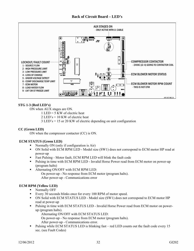
Back of Circuit Board – LED’s
STG 1-3 (Red LED’s)
ON when AUX stages are ON. 1 LED = 5 KW of electric heat 2 LED’s = 10 KW of electric heat 3 LED’s = 15 or 20 KW of electric depending on unit configuration CC (Green LED)
ON when the compressor contactor (CC) is ON. ECM STATUS (Green LED)
Normally ON (only if configuration is Air) ON Solid with ECM RPM LED - Model size (SW1) does not correspond to ECM motor HP read at
power-up Fast Pulsing - Motor fault, ECM RPM LED will blink the fault code Pulsing in time with ECM RPM LED - Invalid Horse Power read from ECM motor on power-up
(program halts) Alternating ON/OFF with ECM RPM LED:
On power-up - No response from ECM motor (program halts). After power-up - Communications error
ECM RPM (Yellow LED)
Normally OFF Every 30 seconds blinks once for every 100 RPM of motor speed. ON Solid with ECM STATUS LED - Model size (SW1) does not correspond to ECM motor HP
read at power-up Pulsing in time with ECM STATUS LED - Invalid Horse Power read from ECM motor on power-
up (program halts). Alternating ON/OFF with ECM STATUS LED:
On power-up - No response from ECM motor (program halts). After power-up - Communications error.
Pulsing while ECM STATUS LED is blinking fast – red LED counts out the fault code every 15 sec. (see Fault Codes)

12/06/2012 33 GI202
ECM FAULT CODES, GENTEQ 3.0 (ECM RPM LED) 1 Pulse = Control temperature above threshold 2 Pulses = Risk Addressed State (RAS), motor locked out 3 Pulses = Start procedure failed or speed too low 4 Pulses = Brownout – supply voltage too low 5 Pulses = Start not successful 6 Pulses = RPM = 0
Service Tips
1. If experiencing both pulsing at same time or both solid ECM LED’s and the program goes to halt, check:
a. ECM motor power cable b. ECM control cable c. Motor size dial switch setting d. Correct motor for the unit model number/type
2. The LED indicated program halt condition requires power-down/power-up reset to clear. 3. Fault codes 2 and 6 cause an immediate hard lockout. 4. Fault codes 1, 3, 4, 5 or no motor data cable communication response will cause a soft lockout as
described in the CSL section. 5. The ECM 3.0 motor has an internal safety function which should overcome potential software
communication problems. a. Will continue at its present operating point. b. If in idle (after stop and no start command) it will stay in idle. c. If running, it will continue running at CFM established by last good data transfer. d. Above mode is set until loss of power or new successful data transfer.
FAULT COUNT (Red LED, left side next to model size dial switch)
Normally OFF Counts out a code for the current fault (see Fault Codes)
PROGRAM FAULT CODES (FAULT COUNT LED): 1 Pulse = Lost Source Flow 2 Pulses = Refrigerant High Pressure Limit (550 psi) 3 Pulses = Refrigerant Low Pressure Limit (40 psi) 4 Pulses = Loss of refrigerant charge 5 Pulses = Under Voltage detect (source voltage less than 195 volts) 6 Pulses = CDT Safety Limit (230 degrees) 7 Pulses = See ECM Motor Fault section 8 Pulses = Lost load water flow (THA & THT units only) 9 Pulses = Leaving source water or load freeze limit

12/06/2012 34 GI202
High and Low Pressure Switches – The heat pump is equipped with both high and low pressure switches that shut the unit off if the refrigerant pressure exceeds 550 PSI or goes below 40 PSI. Do not reset a system in the heating mode without first verifying water flow.
WARNING DO NOT RESET THE SYSTEM MORE THAN ONCE – REPEATED RESETTING OF THE LOCKOUT CAN CAUSE SERIOUS DAMAGE. IF A REPEAT LOCKOUT OCCURS CONTACT YOUR SERVICE DEALER IMMEDIATELY.
User Visual Warnings Various front panel LED’s have pulsing indication when certain key temperature parameters reach a point where system corrective action is advised. GEO Logic has default points where the manufacturer feels notification should be made. When any one of these temperature points is reached the compressor is shut down for 2 x ACD’s (6 min.). At the end of this shutdown delay the compressor will again be activated as an automatic reset type function. This does not lead to a lockout, it is simply a warning and a pause in the system for possible system correction or notification for further service action. These LED’s will be pulsing during the 2 x ACD (6 min.) shutdown/auto reset cycle.
Function Sensor Default Air
Values Trip Point
Increase Decrease Differential
Lo pressure ST 35° √ 3° Hi pressure ST 110° √ 5° Loop temp. LWT 39° open, 20° closed √ - AUX HL Internal Fixed √ 20°

12/06/2012 35 GI202
Power On Startup Before applying power to the heat pump, check the following items:
1. All plumbing and ductwork to the heat pump is complete and operational.
2. Low voltage wiring of the thermostat and any additional control wiring is complete.
3. Set thermostat to the OFF position.
4. All high voltage wiring is correct including disconnect and wire sizes.
5. The heat pump is located in a warm area above 50°F [10°C]. Starting the system with low ambient temperature conditions is more difficult.
6. You may now apply power to the unit. A 3 minute delay on power up is programmed into the GEO Logic board before the compressor will operate. This delay prevents short cycling of the unit. Note there may be additional time delays caused by the thermostat.
7. Verify source water flow – specification page.
Open loop systems - manually open water solenoid valve on well system to check flow.
Closed loop systems – operate earth loop pumps to verify flow of antifreeze protected loop fluid.
The following steps will assure that your system is heating and cooling properly. After the initial time delay is completed the heat pump is now ready for operation. It is during these steps the information is collected to complete the ‘Forced Air Heat Pump Operational Statistics’ sheet. This sheet is the top page of this manual. It should be removed, filled out and kept with the manual for future reference.
1. Do not connect refrigerant gauges to this unit unless the data collected indicates there is a problem.
2. Place the thermostat to the “HEAT” position. Turn the thermostat up to activate a 1st stage call for heat. Pumps have an initial purge cycle, then compressor and blower will start. Check and record source water flow rate in GPM, see specification chart at the beginning of this
manual for minimum water flow requirement. Check and record antifreeze protection level.
3. After the unit has run for about 3 minutes.
Check and record the source side supply and return water temperatures. Check and record the supply and return air temperatures. Check and record the running voltage. Check and record the total amp draw. Check and record the compressor amp draw.
4. Raise the thermostat only enough to call 2nd stage (if applicable). Again wait 3 minutes.
Check and record the source side supply and return water temperatures. Check and record the supply and return air temperatures. Check and record the running voltage. Check and record the total amp draw. Check and record the compressor amp draw.
5. Raise the thermostat to call for AUX electric heat. Wait 3 minutes.
Check and record the supply and return air temperatures Check and record the amp draw on the electric module.
6. Turn the thermostat to the off position. The compressor will shut down in a few seconds. Blower will
continue to the end of the purge cycle.

12/06/2012 36 GI202
7. Place the thermostat in the “COOL” position. Turn the thermostat down to activate a 1st stage call for
cooling. The compressor will start after a 3 minute ACD period from its last shutdown. The compressor and blower will start.
8. After the unit has run about 3 minutes.
Check and record the source side supply and return water temperatures. Check and record the supply and return air temperatures. Check and record the running voltage. Check and record the total amp draw. Check and record the compressor amp draw.
9. Raise the thermostat only enough to call 2nd stage (if applicable)
Check and record the source side supply and return water temperatures. Check and record the supply and return air temperatures. Check and record the running voltage. Check and record the total amp draw. Check and record the compressor amp draw.
10. Be sure all operational data has been collected and recorded on the ‘FA Heat Pump Operational
Statistics’ sheet. 11. Reset the thermostat to normal mode and temperature settings for the season.
12. Instruct the owner on correct operation of the thermostat and heat pump system.
12/06/2012 37 GI202
Operational Tips GEO Logic - The GEO Logic board performs the functions controlling the compressor operation, system lockout, compressor anti-short cycle, and a three minute delay after power is applied. Review Operational Indicator section on page 30 of this manual before proceeding. Pump/Blower Purge – a stat Y call starts the blower motor, loop source pump, open loop solenoid, and desuperheater pump. The stat-Y call to CSL is delayed by 5 seconds. These four items allow for “circulation” before the compressor is turned on. The blower motor has a 45-second turn on ramp thus it will not be noticeable during this 5-second start purge. After the time delay expires, the compressor contactor will be energized as long as the high and low pressure switches are closed. If either switch is open after the delay expires, the compressor will not energize. If either switch opens while the compressor is energized, it will de-energize immediately and begin the anti-short cycle delay. The compressor will not be allowed to turn on again until the 2 X ACD (6 minutes) expires and both pressure switches are closed. If the GEO Logic controller experiences three high pressure, low pressure soft lockouts in a single thermostat call period, it will hard lock out the compressor. During both hard and soft lockouts the fault codes are displayed. The flow switch has a bypass timer in which the GEO Logic board will ignore an open flow switch for the first 15 seconds. If the flow switch opens the GEO Logic controller will de-energize the compressor and initiate a single soft lockout. If the GEO Logic controller experiences a second flow switch fault during a single thermostat call period, it will hard lock out the compressor.
NOTE
This is a fluid flow limit switch; it is not a GPM sensor for determining adequate flow. It is only a flow indicator, and cannot be used to determine minimum required flow. A manual reset of power will be required to reset any hard lockout condition.
At stat-Y call end, loop source pump, desuperheater pump, and solenoid turn off immediately. Blower continues for 30 seconds (after the 30 seconds the blower will start its 45 second ramp down).
Problems that could cause a lockout situation include: 1. Water flow problems 2. Air flow problems 3. Internal heat pump operation problems 4. Excessive cold water temperature conditions, source and load 5. Excessive hot water temperature conditions, source and load 6. Under Voltage (source voltage less than 195 volts)
The GEO Logic control has a CSL Fault Count LED to indicate which type of fault or lockout has occurred.
The ACD function puts a time-out period of 3 minutes on the compressor before re-starting on a normal cycle.. This function protects the compressor from repeated on/off operation in the event of a loose wire or faulty thermostat.

12/06/2012 38 GI202
ECM Blower Motor Hardware and Sequence – GEO-Logic is equipped and programmed to operate with a Modbus/RS485 ECM motor. Each size motor is characterized to its assigned blower wheel/housing for CFM.
ECM motor start is coincident with stat-Y, W2, E. Programmed within the ECM motor is a 45-second ramp-up and ramp-down.
The Y2 CFM becomes the reference point. There is a heat and cool Y2 CFM recorded within the GEO-LOGIC™ board. An 8-position dial switch selects the Y2 CFM relating to applicable installed model size. All model sizes do not have to be available or active; this is an assignment relating to the dial switch.
Model Size Switch is directly below the 10 terminal thermostat block. Dial
Switch Model Size ECM HP
Y2 Heat CFM
Y2 Cool CFM
0 TVT-024 ¾ 850 979 2 TVA/TVT-036 ¾ 1200 1288 3 TVT-042 ¾ 1312 1442 4 TVA/TVT-048 ¾ 1500 1648 6 TVA/TVT-060 1 1875 2060
The thermostat wired functions have an assigned CFM related to the above. Also, the Y2/Y1 CFM can be further modified by the thermostat functions.
Stat FL Comp PL/FL Comp Modifier Remarks
O Determines heat/cool
Y X 1.00 X 0.75 Y2 X 1.00 G X 0.40 X 0.40
W2 +15% PCC-20 E X 1.00 X 1.00 -20% PCC-22
HUM -15% PCC-21
Y1 and Y2 can be fine-tuned or tweaked with a 4-position dial switch. This relates to both the Y1 and Y2 CFM for the selected model size dial switch. The 4-positions are 0%, -6%, +6%, +12%. The Y1 and Y2 tweak switch is found directly below the Model Size Switch.
Note: This table is to show example calculations for Y and Y2 in COOLING 0% -6% +6% +12%
Model Size Y Y2 Y Y2 Y Y2 Y Y2
TVT – 024 640 980 600 750 680 1040 715 1100 TVT – 036 900 1290 845 1210 955 1370 1010 1445 TVT – 042 985 1440 925 1350 1045 1525 1100 1615 TVT – 048 1125 1650 1060 1550 1195 1750 1260 1850 TVT – 060 1400 2060 1315 1935 1485 2185 1570 2300
CFM Rounded
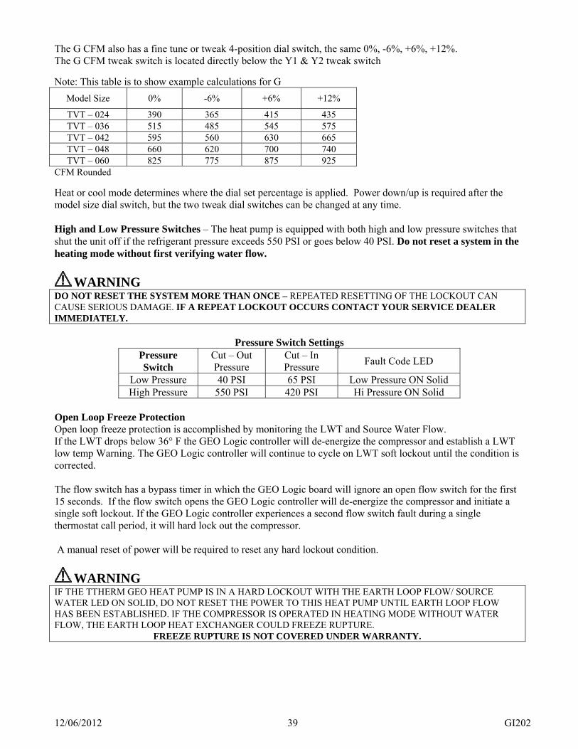
12/06/2012 39 GI202
The G CFM also has a fine tune or tweak 4-position dial switch, the same 0%, -6%, +6%, +12%. The G CFM tweak switch is located directly below the Y1 & Y2 tweak switch
Note: This table is to show example calculations for G
Model Size 0% -6% +6% +12%
TVT – 024 390 365 415 435 TVT – 036 515 485 545 575 TVT – 042 595 560 630 665 TVT – 048 660 620 700 740 TVT – 060 825 775 875 925
CFM Rounded
Heat or cool mode determines where the dial set percentage is applied. Power down/up is required after the model size dial switch, but the two tweak dial switches can be changed at any time. High and Low Pressure Switches – The heat pump is equipped with both high and low pressure switches that shut the unit off if the refrigerant pressure exceeds 550 PSI or goes below 40 PSI. Do not reset a system in the heating mode without first verifying water flow.
WARNING DO NOT RESET THE SYSTEM MORE THAN ONCE – REPEATED RESETTING OF THE LOCKOUT CAN CAUSE SERIOUS DAMAGE. IF A REPEAT LOCKOUT OCCURS CONTACT YOUR SERVICE DEALER IMMEDIATELY.
Pressure Switch Settings Pressure Switch
Cut – Out Pressure
Cut – In Pressure Fault Code LED
Low Pressure 40 PSI 65 PSI Low Pressure ON Solid High Pressure 550 PSI 420 PSI Hi Pressure ON Solid
Open Loop Freeze Protection Open loop freeze protection is accomplished by monitoring the LWT and Source Water Flow. If the LWT drops below 36° F the GEO Logic controller will de-energize the compressor and establish a LWT low temp Warning. The GEO Logic controller will continue to cycle on LWT soft lockout until the condition is corrected. The flow switch has a bypass timer in which the GEO Logic board will ignore an open flow switch for the first 15 seconds. If the flow switch opens the GEO Logic controller will de-energize the compressor and initiate a single soft lockout. If the GEO Logic controller experiences a second flow switch fault during a single thermostat call period, it will hard lock out the compressor. A manual reset of power will be required to reset any hard lockout condition.
WARNING IF THE TTHERM GEO HEAT PUMP IS IN A HARD LOCKOUT WITH THE EARTH LOOP FLOW/ SOURCE WATER LED ON SOLID, DO NOT RESET THE POWER TO THIS HEAT PUMP UNTIL EARTH LOOP FLOW HAS BEEN ESTABLISHED. IF THE COMPRESSOR IS OPERATED IN HEATING MODE WITHOUT WATER FLOW, THE EARTH LOOP HEAT EXCHANGER COULD FREEZE RUPTURE.
FREEZE RUPTURE IS NOT COVERED UNDER WARRANTY.

12/06/2012 40 GI202
Preventive Maintenance Air Filter Maintenance – The Dust Free air filter in your TTHERM GEO is designed for optimum performance and long life. However, a dirty filter will result in lower efficiency and performance. Periodically, the filter should be thoroughly pressure washed in the opposite direction of airflow. Under normal operating conditions, a monthly cleaning should be satisfactory. Water Coil Maintenance –In closed loop systems, water coil maintenance is generally not needed. However, if a dirty installation or deterioration of the piping has caused debris to accumulate in the system, the water coil should be cleaned using standard cleaning procedures. For open loop systems installed in areas with a high mineral content, it is best to schedule regular periodic maintenance to inspect and clean the coil if necessary. Should cleaning become necessary, do so using the following standard cleaning procedure:
Chlorine Cleaning (Bacterial Growth) 1. Turn thermostat to “Off” position. 2. Connect a circulating pump to hose bibs on entering water and leaving waterside of heat exchanger. 3. Using a five-gallon pail of water add chlorine bleach mixture. The chlorine should be strong enough to
kill the bacteria. Suggested initial mixture is 1 part chlorine bleach to 4 parts water. 4. Close shut off valves upstream and downstream of heat exchanger. 5. Open hose bibs to allow circulation of bleach solution. 6. Start pump and circulate solution through heat exchanger for 15 minutes to one hour. Solution should
change color to indicate the chlorine is killing the bacteria and removing it from the heat exchanger. 7. Flush used solution down the drain by adding fresh water supply. Flush until leaving water is clear. 8. Repeat procedure until solution runs clear through the chlorine circulation process. 9. Flush entire heat pump system with water. This procedure can be repeated annually, semiannually, or
as often as it takes to keep bacteria out of the heat exchanger, or when bacteria appears in a visual flow meter to the point the flow cannot be read.
Muriatic Acid Cleaning - (Difficult Scaling and Particle Buildup Problems) Consult installer due to dangerous nature of acids. “Iron out” solutions and de-scaling products are also useful.
Condensate Drip Pan and Drain –Inspection and cleaning of the condensate drain system during the cooling season will help prevent the system from plugging up, potentially causing water damage to your structure and floor coverings. Inspect the flexible “P-trap” to make certain it remains clear of obstructions. In some areas, airborne bacteria can cause algae to grow in the drip pan. In these areas, it may be necessary to treat the drain pan with an algae inhibiting chemical, as this algae together with lint and dust could plug the drain piping. Blower Motors – All TTHERM GEO’s are equipped with factory sealed bearing blower motors. These motors never need additional lubrication for the life of the motor. Oiling is not recommended, as excess oil will attract lint and dust. Air Coil – In order to keep your TTHERM GEO operation at peak efficiency, the air coil should be inspected and cleaned when necessary. If the coil is excessively dirty, the coil can be cleaned with a household vacuum cleaner and a soft brush. The aluminum fins are fragile and bend easily, so take great care not to damage the fins, and remember, these fins are sharp, so take the needed safety precautions.

12/06/2012 41 GI202
Unit Operating Conditions - Heat
Model StageSource Temp
Source temp Δ GPM
Air temp Δ Amps 240
Blower AMPS
CFMDischarge PSI @ 68° return air
Discharge gas temp
Sub cool at TXV
Suction pressure
Suction temp at
bulb
Super- heat at
bulb2 32 1.9-3.9 10 26-31 7.2-9.2 1.0 800-840 324-344 165-171 10.0-14.0 83-93 34-40 10-142 50 5.6-7.6 10 33-38 8.1-10.1 1.1 810-850 368-388 165-171 11.0-15.0 114-124 48-54 10-14
TVT-024 2 68 5.8-7.8 10 42-47 9.4-11.4 1.2 820-860 423-443 169-175 11.0-15.0 152-162 65-71 10-141 41 2.0-4.0 10 24-29 5.3-7.3 0.9 720-760 308-328 152-158 6.5-10.5 102-112 43-49 10-141 50 2.5-4.5 10 27-32 5.4-7.4 0.9 720-760 326-346 153-159 6.5-10.5 120-130 51-57 10-141 68 4.4-6.4 10 33-38 5.8-7.8 0.9 710-750 365-385 154-160 6.0-10.0 155-165 67-73 12-16
2 32 3.8-5.8 9 25-30 10.6-12.6 1.8 1170-1210 302-322 155-161 10.0-14.0 75-85 32-38 11-152 50 5.9-7.9 9 32-37 11.9-13.9 1.9 1180-1220 340-360 155-161 11.0-15.0 106-116 47-53 11-15
TVT-036 2 68 8.3-10.3 9 39-44 13.8-15.8 1.9 1180-1220 385-405 157-163 11.4-15.4 145-155 62-68 10-141 41 3.5-5.5 9 24-29 7.5-9.5 1.3 980-1020 295-315 147-153 7.0-11.0 98-108 41-47 10-141 50 3.8-5.8 9 28-33 7.5-9.5 1.3 980-1020 312-332 148-154 7.0-11.0 115-125 48-54 10-141 68 6.2-8.2 9 33-38 7.9-9.9 1.3 1000-1040 346-366 145-161 6.6-10.6 152-162 66-72 11-15
2 32 3.7-5.7 10.5 24-29 12.4-14.4 2.4 1300-1340 303-323 158-164 10.0-14.0 76-86 32-38 12-162 50 5.6-7.7 10.5 31-36 13.9-15.9 2.4 1300-1340 342-362 154-160 10.5-14.2 107-117 45-51 10-14
TVT-042 2 68 8.2-10.2 10.5 37-42 15.9-17.9 2.4 1310-1350 382-402 158-164 9.3-13.3 143-153 61-67 10-141 41 3.3-5.3 10.5 23-28 8.6-10.6 1.8 1090-1130 290-310 150-156 7.1-11.1 96-106 42-48 11-151 50 3.8-5.8 10.5 26-31 8.9-10.9 1.8 1080-1120 310-330 144-150 6.5-10.5 114-124 49-55 10-141 68 6.1-8.1 10.5 32-37 9.6-11.6 1.8 1080-1120 347-367 141-147 5.1-9.1 152-162 65-71 10-14
2 32 4.0-6.0 12 27-32 16.6-18.6 2.7 1480-1520 323-343 168-174 8.0-12.0 76-86 31-37 12-162 50 5.9-7.9 12 34-39 18.6-20.6 2.8 1480-1520 365-385 166-172 10.6-14.6 105-115 44-50 10-14
TVT-048 2 68 8.6-10.6 12 41-46 21.0-23.0 2.8 1490-1530 410-430 168-174 10.0-14.0 140-150 59-65 9-131 41 3.5-5.5 12 25-30 11.8-13.8 1.8 1160-1200 310-330 163-169 4.2-10.2 98-108 43-49 11-151 50 3.9-5.9 12 28-33 12.3-14.3 1.9 1180-1220 328-348 163-169 5.4-9.5 113-123 49-55 11-151 68 6.4-8.4 12 35-40 12.9-14.9 2.0 1180-1220 368-388 153-159 6.4-10.4 152-162 64-70 10-14
2 32 3.6-5.6 15 27-32 19.0-21.0 4.1 1830-1870 318-338 163-169 10.0-14.0 75-85 30-36 10-142 50 5.7-7.7 15 34-39 20.9-22.9 4.2 1840-1880 360-380 162-168 11.0-15.0 103-113 45-51 11-15
TVT-060 2 68 8.5-10.5 15 42-47 23.2-25.2 4.2 1840-1880 410-430 167-173 16.0-20.0 139-149 60-66 11-151 41 3.5-5.5 15 27-32 14.8-16.8 2.9 1510-1550 316-336 160-166 7.0-11.0 95-105 40-46 10-141 50 4.0-6.0 15 31-36 15.3-17.3 2.9 1520-1560 338-358 157-163 9.0-13.0 113-123 47-53 10-141 68 6.4-8.4 15 38-43 16.3-18.3 3.0 1520-1560 375-395 158-164 11.0-15.0 148-158 63-39 11-15

12/06/2012 42 GI202
Unit Operating Conditions - Cool
Model StageSource Temp
Source temp ∆ GPM
Air temp Δ Dry bulb
Amps 240Blower AMPS
CFMDischarge
pressure at 80° return air
Discharge gas temp
Sub-cool at TXV
Suction pressure
Suction temp at bulb
Super-heat at bulb
2 50 6.6-8.6 10 21.3-26.3 5.2-7.2 1.6 940-980 194-214 111-117 2.0-6.0 129-139 58.0-64.0 13.0-17.02 59 6.2-8.2 10 21.0-26.0 5.5-7.5 1.6 940-980 218-238 116-122 2.0-6.0 133-143 58.6-64.6 12.5-16.52 77 5.6-7.6 10 19.7-24.7 6.8-8.8 1.6 930-970 280-300 135-141 2.0-6.0 136-146 60.4-66.4 12.6-16.6
TVT-024 2 86 5.0-7.0 10 18.9-23.9 7.6-9.6 1.6 930-970 318-338 144-150 2.2-6.2 138-148 60.8-66.8 11.8-15.61 50 4.4-6.4 10 19.3-24.3 2.7-4.7 1.3 850-890 170-190 100-106 2.0-6.0 137-147 61.8-67.8 13.3-17.31 59 4.3-6.3. 10 19.4-24.4 3.3-5.3 1.3 850-890 205-225 106-112 2.0-6.0 139-149 60.8-66.8 11.5-15.51 68 4.4-6.4 10 18.8-23.8 3.6-5.6 1.3 850-890 230-250 116-122 2.0-6.0 142-152 62.6-68.6 11.9-15.91 86 3.4-5.4 10 17.6-23.6 5.0-7.0 1.3 850-890 305-325 138-144 2.0-6.0 145-155 63.7-69.7 11.7-15.7
2 50 10.9-12.9 9 21.5-26.5 8.6-10.6 2.0 1230-1250 212-232 124-130 5.3-9.3 121-131 62.0-68.0 20.4-24.42 59 8.1-10.1 9 21.0-26.0 9.4-11.4 2.1 1240-1280 236-256 124-130 4.1-8.1 128-138 60.5-66.5 16.0-20.42 77 8.1-10.1 9 20.4-25.4 11.2-13.2 2.1 1240-1280 300-320 138-144 3.8-7.8 133-143 61.3-67.3 14.5-18.5
TVT-036 2 86 8.2-10.2 9 20.0-25.0 12.3-14.3 2.1 1240-1280 338-358 148-154 5.4-9.4 135-145 61.8-67.8 14.2-18.21 50 7.3-9.3 9 20.0-25.0 4.6-6.6 1.5 1030-1070 185-205 108-114 3.5-7.5 128-138 62.6-68.6 18.4-22.41 59 7.6-9.6 9 20.0-25.0 5.0-7.0 1.5 1240-1280 214-234 112-118 2.4-6.4 135-145 61.7-67.7 14.1-18.11 68 7.6-9.6 9 19.0-24.0 5.8-7.8 1.5 1040-1080 250-270 120-126 2.1-6.1 141-151 63.1-69.1 12.6-16.61 86 6.8-8.8 9 18.6-23.6 7.3-9.3 1.5 1040-1080 313-333 139-145 2.1-6.1 144-154 63.6-69.6 12.1-16.1
2 50 9.7-11.7 10.5 18.6-23.6 10.3-12.3 2.8 1480-1520 207-227 127-133 7.3-11.3 114-124 62.8-68.8 24.5-28.52 59 10.4-12.4 10.5 19.0-24.0 10.9-12.9 2.5 1410-1430 235-255 128-134 5.5-9.5 122-132 58.7-64.7 16.9-20.92 77 9.6-11.6 10.5 17.8-22.8 12.9-14.9 2.6 1400-1440 297-317 141-147 3.8-7.8 127-137 59.0-65.0 14.9-18.9
TVT-042 2 86 9.2-11.2 10.5 17.6-22.6 14.2-16.2 2.6 1380-1420 334-354 151-157 3.7-7.7 132-142 60.8-66.8 14.7-18.71 50 7.1-9.1 10.5 18.6-23.6 5.6-7.6 1.9 1210-1250 189-209 106-112 5.6-9.6 124-134 61.3-67.3 18.5-22.51 59 7.4-9.4 10.5 18.0-23.0 6.1-8.1 1.8 1150-1190 216-236 112-118 3.9-7.9 132-142 60.3-66.3 14.1-18.11 68 7.3-9.3 10.5 17.6-22.6 6.9-8.9 1.9 1140-1180 244-264 117-123 3.1-7.1 133-143 59.7-65.7 13.0-17.01 86 6.4-8.4 10.5 20.0-25.0 8.8-10.8 1.8 1130-1170 313-333 138-144 2.9-8.9 136-146 60.6-66.6 12.5-16.5
2 50 12.6-14.6 12 22.0-27.0 13.2-15.2 3.2 1540-1580 228-248 117-123 6.1-10.1 133-143 60.1-66.1 13.3-17.32 59 12.3-14.3 12 21.3-26.3 15.9-17.9 3.0 1540-1580 252-272 126-132 5.1-9.1 133-143 59.7-65.7 13.0-17.02 77 10.6-12.6 12 20.0-25.0 16.2-18.2 3.1 1550-1590 310-330 141-147 5.3-9.3 136-146 61.0-67.0 13.1-17.1
TVT-048 2 86 9.6-11.6 12 19.8-24.8 17.8-19.8 3.0 1550-1590 352-372 152-158 6.8-10.8 137-147 61.4-67.4 12.9-16.91 50 8.9-10.9 12 21.3-26.3 7.0-9.0 1.9 1240-1280 200-220 104-110 3.5-7.5 142-152 63.2-69.2 12.8-16.81 59 8.9-10.9 12 20.2-25.2 8.0-10.0 2.0 1260-1300 226-246 114-120 2.7-6.7 140-150 61.9-67.9 12.1-16.11 68 8.4-10.4 12 19.6-24.6 8.8-10.8 2.0 1260-1300 252-272 122-128 2.5-6.5 142-152 62.5-68.5 12.0-16.01 86 7.2-9.2 12 18.4-23.4 11.3-13.3 2.3 1280-1320 321-341 148-154 4.0-8.0 144-154 64.9-70.9 13.1-17.1
2 50 9.1-11.1 15 21.2-26.2 15.2-17.2 4.7 1920-1960 220-240 130-136 10.4-14.4 123-133 64.5-70.5 22.3-26.32 59 11.0-13.0 15 21.0-26.0 17.2-19.2 4.9 1960-2000 251-271 136-142 10.3-14.3 129-139 64.6-70.6 19.6-23.62 77 10.6-12.6 15 20.5-25.5 19.5-21.5 4.8 1950-1990 313-333 147-153 8.9-12.9 132-142 61.9-67.9 15.6-19.6
TVT-060 2 86 10.0-12.0 15 18.9-23.9 21.1-23.1 4.7 1950-1990 351-371 157-163 10.9-14.9 136-146 64.6-70.6 16.5-20.51 50 7.6-9.6 15 21.5-26.5 9.3-11.3 3.1 1600-1640 202-222 118-124 7.2-11.2 127-137 64.2-70.2 20.2-24.21 59 7.9-9.9 15 19.0-24.0 10.3-12.3 3.1 1610-1650 229-249 125-131 8.7-12.7 132-142 65.7-71.7 19.4-23.41 68 8.0-10.0 15 20.0-25.0 11.2-13.2 3.1 1660-1700 256-276 128-134 8.3-12.3 138-148 63.4-69.4 14.5-18.51 86 7.1-9.1 15 20.0-25.0 14.2-16.2 3.1 1590-1630 323-343 149-155 7.6-11.6 138-148 64.4-70.4 15.3-19.3
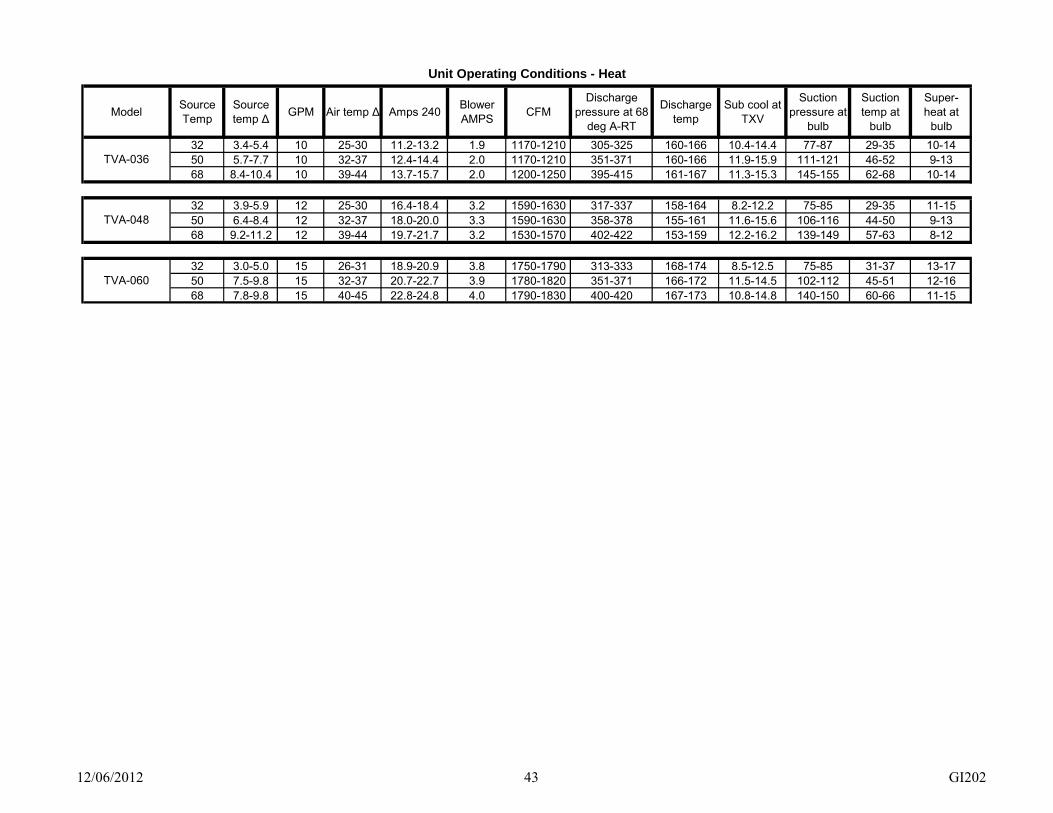
12/06/2012 43 GI202
Unit Operating Conditions - Heat
ModelSource Temp
Source temp Δ GPM Air temp Δ Amps 240
Blower AMPS
CFMDischarge
pressure at 68 deg A-RT
Discharge temp
Sub cool at TXV
Suction pressure at
bulb
Suction temp at
bulb
Super- heat at
bulb
32 3.4-5.4 10 25-30 11.2-13.2 1.9 1170-1210 305-325 160-166 10.4-14.4 77-87 29-35 10-1450 5.7-7.7 10 32-37 12.4-14.4 2.0 1170-1210 351-371 160-166 11.9-15.9 111-121 46-52 9-1368 8.4-10.4 10 39-44 13.7-15.7 2.0 1200-1250 395-415 161-167 11.3-15.3 145-155 62-68 10-14
32 3.9-5.9 12 25-30 16.4-18.4 3.2 1590-1630 317-337 158-164 8.2-12.2 75-85 29-35 11-1550 6.4-8.4 12 32-37 18.0-20.0 3.3 1590-1630 358-378 155-161 11.6-15.6 106-116 44-50 9-1368 9.2-11.2 12 39-44 19.7-21.7 3.2 1530-1570 402-422 153-159 12.2-16.2 139-149 57-63 8-12
32 3.0-5.0 15 26-31 18.9-20.9 3.8 1750-1790 313-333 168-174 8.5-12.5 75-85 31-37 13-1750 7.5-9.8 15 32-37 20.7-22.7 3.9 1780-1820 351-371 166-172 11.5-14.5 102-112 45-51 12-1668 7.8-9.8 15 40-45 22.8-24.8 4.0 1790-1830 400-420 167-173 10.8-14.8 140-150 60-66 11-15
TVA-060
TVA-036
TVA-048

12/06/2012 44 GI202
Unit Operating Conditions - Cool
ModelSource Temp
Source temp ∆ GPM
Air temp Δ Dry bulb
Amps 240Blower AMPS
Nominal CFM
Discharge pressure at 80 deg A-
RT
Discharge temp
Sub-cool at TXV
Suction pressure at
bulb
Suction temp at
bulb
Super-heat at bulb
50 8.5-10.5 10 20-25 7.6-9.6 2.1 1210-1250 197-217 109-115 4.6-8.6 119-129 55-61 14.5-18.559 8.9-10.9 10 21-26 8.6-10.6 2.3 1240-1280 230-250 120-126 5.5-9.5 124-134 57-63 13.8-17.877 8.0-10.0 10 19-24 10.5-12.5 2.2 1240-1280 293-313 137-143 7.0-11.0 127-137 57-63 12.8-16.886 6.8-8.8 10 20-25 11.7-13.7 2.2 1230-1270 324-344 149-155 8.3-12.3 123-133 55-61 12.1-16.1
50 11.6-13.6 12 22-27 7.2-9.2 3.3 1670-1710 223-243 110-116 6.3-10.3 130-140 57-63 12.0-16.059 11.3-13.3 12 22-27 12.4-14.4 3.3 1680-1720 243-263 115-121 7.7-11.7 131-141 57-63 11.8-15.877 10.6-12.6 12 20-25 15.3-17.3 3.3 1680-1720 309-329 134-140 7.6-11.6 133-143 58-64 11.4-15.486 10.0-12.0 12 20-25 17.0-19.0 3.3 1680-1720 350-370 144-150 8.8-12.8 135-145 59-65 11.2-15.2
50 10.4-12.4 15 20-25 14.2-16.2 5.1 2010-2050 219-239 122-128 7.0-11.0 129-139 64-70 19.4-23.459 10.6-12.6 15 19-24 15.5-17.5 5.2 2030-2070 243-263 127-133 7.0-11.0 133-143 65-71 18.7-22.777 9.6-11.6 15 18-23 18.6-20.6 5.2 2040-2080 307-327 145-151 9.5-13.5 137-147 67-73 18.3-22.386 8.8-10.8 15 17-22 20.4-22.4 5.2 2050-2090 342-362 156-162 7.2-11.2 138-148 68-74 18.8-22.8
TVA-060
TVA-036
TVA-048

12/06/2012 45 GI202
Troubleshooting – GEO Logic Control
Sensor Temperature Calibration – all four remote sensors are digital electronic and factory calibrated. Normally these do not require field calibration or verification. However, if sensor temperature error is determined, use special PC software and PC USB port cable. The PC screen has direct readout of the four monitored temperatures, it allows a visual determination of temperature settings, and can be used to offset the temperature sensors for troubleshooting and demonstration purposes.
NOTE
Temperature Sensors Temperature sensors installed in TTHERM GEO heat pumps are NOT thermisters. They are digital devices calibrated at the manufacturer. They are polarity sensitive. Be sure to connect the red and white wires in their correct shared terminals. The black wire is the data stream wire and will have its own screw terminal.
Bad sensor, safety – if the internal logic detects open sensor wire, a shorted sensor wires, or an incorrectly wired sensor; the green POWER LED reverts to a pulsing mode.
Bad sensor, operating default condition – the detection of bad sensor forces the controller to a fixed stage operation. Software declared bad sensor default – ST = 70° F, LWT (heating) = 32°F, LWT (cooling) = 77° F, CDT = 200° F, DDT = 190° F.
Check the GEO Logic Controller section of this manual for in depth description of the diagnostic information available by observing the LED’s.
Internal fuses – the source loop, hydronic loop pumps, and desuperheater pump are fused on the high voltage pump relay board. The pump hookup decal provides the fuse size and details.
Troubleshooting/Repair Helps 1. This GEO Logic controller contains several interference suppression components, but as an electronic
logic product, unpredictable and unusual transients or interferences may sometimes cause strange results. If the GEO Logic controller is “acting strange”, one immediate step would be power down reset. Simply turn off the 240 volt source power. When the green POWER LED goes out, count to 10, and re-energize power supply.
2. The terminal blocks for control wire hook-up are designed for a wire insertion and screw clamp down. If there is no wire connected and the screw is loose, the screw may not necessarily make a good electrical contact to the inside components. Example – if you jumper the thermostat terminals without thermostat wire connection or if you are attempting to measure voltage on the screw head, you may get erroneous or unpredictable results if the screw is not tightened down.
3. Use general heating/heat pump system logic information and basic understanding of the terminal block wiring functions when measuring voltage to determine proper operation.
Open/Closed Loop Operation – TTHERM GEO heat pumps are factory set for open loop operation. Open/Closed loop operation is set with Jumper J 11 on the left side of the GEO Logic controller. The jumper must be in place on J11 if the unit is operated on an open loop. The GEO Logic controller protects the heat exchanger from freezing by causing the compressor to shut down when the leaving water temperature reaches 38° F open loop and 20° F closed loop. The compressor will remain off for 2 ACD’s, and the EARTH LOOP FLOW/ SOURCE WATER LIMIT & HP STAGE 1 LED’s will pulse, while the water runs and warms up. The compressor will then restart again providing heat until the LWT again reaches 38° F open loop and 20° F closed loop. If this routine continues the heat pump will not be able to maintain the temperature in the house and the backup heat will come on. Possible causes would include: Open Loop Closed Loop 1. Supply water filter that needs cleaning 1. Inadequate source water flow 2. Inadequate source water flow 2. Antifreeze protection inadequate 3. Water discharge line that is plugging up 3. Heat exchanger needs to be cleaned 4. Entering water temperature less than 50 degrees 5. Heat exchanger needs to be cleaned

12/06/2012 46 GI202
WARNING IF THE TTHERM GEO HEAT PUMP IS IN A HARD LOCKOUT WITH THE EARTH LOOP FLOW/ SOURCE WATER LED ON SOLID, DO NOT RESET THE POWER TO THIS HEAT PUMP UNTIL EARTH LOOP FLOW HAS BE ESTABLISHED. IF THE COMPRESSOR IS OPERATED IN HEATING MODE WITHOUT WATER, FLOW THE EARTH LOOP HEAT EXCHANGER COULD FREEZE RUPTURE. FREEZE RUPTURE IS NOT COVERED UNDER WARRANTY.
Troubleshooting the Relay board The relay board has 4 LED’s which display which relay is closed. Yellow – is on when open loop water solenoid is energized. Green – is on when the source loop pump is running. Red – is on when the desuperheater pump relay has SWH red wire at L2 voltage. Blue – is on when the 2nd source loop pump is running. The relay board has 2 – 10 amp fuses providing power for source loop, hydronic, and the desuperheater pumps. These fuses are 10 Amp type GSF. Checking the high voltage input terminals
The high voltage enters the relay board on the upper left side, terminals W1 & W2. This high voltage comes from the source side of the contactor – L1 is connected to W1 and L2 is connected to W2.
WARNING DISCONNECT ALL ELECTRICAL POWER BEFORE ELECTRICALLY CONNECTING OR SERVICING THE UNIT. FAILURE TO DISCONNECT THE ELECTRICAL POWER BEFORE WORKING ON THIS PRODUCT CAN CREATE A HAZARD LEADING TO PERSONAL INJURY OR DEATH.
Checking the high voltage output terminals The high voltage leaves the relay board in 2 locations.
1. Terminal Block (TB1) is located in the upper right side of the relay board. See the decal located to the right of the TB1 to determine wiring. High voltage should be present at the respective terminals when the corresponding LED is on Load pump terminals will be hot at the same time as source pump terminals.
Tip – if source voltage is present on the board one of the LEDs is on and high voltage is not present at the corresponding terminals the switching relay is bad and the board will need to be replaced.
2. One of the desuperheater terminals (SWH) is located between the fuses and the other SHW terminal
is below the fuses. These terminals carry High Voltage. To determine if the desuperheater pump has power measure across these two terminals. If a desuperheater pump needs to be disabled be sure the high voltage to the TTHERM GEO heat pump is disabled. Remove the SHW wire from between the fuses and place it on the parking tab (P) above the relays.
The relay board has one low voltage output for the 24 volt AC water solenoid. The 24VAC “common” wire is gray and is connected to terminal T7 on the right side of the relay board. The 24VAC “hot” wire is brown/yellow and is connected to terminal T4.
Tip – if the yellow LED #4 is on and the low voltage is not present at the water solenoid terminals, the switching relay is bad and the board will need to be replaced.

12/06/2012 47 GI202
Troubleshooting – General
WARNING – Refrigerant Evacuation
WHEN REFRIGERANT IS EVACUATED FROM A UNIT WITHOUT ANTIFREEZE IN THE WATER TO REFRIGERANT HEAT EXCHANGERS, WATER IN THE UNPROTECTED HEAT EXCHANGER MUST BE REMOVED OR CONTINUOUSLY FLOWING TO AVOID A POTENTIAL HEAT EXCHANGER FAILURE CAUSED BY FREEZE RUPTURE. FLOWING WATER THROUGH THE HEAT EXCHANGERS EVEN IF ANTIFREEZE PROTECTED WILL SPEED THE EVACUATION PROCESS.
Troubleshooting Guide for Water-to-Air Geothermal “Heating”
Head pressure
Subcool Suction pressure
Superheat Compressor Amp Draw
Air temp differential
Source temp differential
Undercharged system Low Low Low High Low Low Low
Overcharged system High High High Low High High High
Low air flow High Low High High High High Low
High air flow Low Low High High High Low High
Low source flow Low High Low Low Low Low High
High source flow High Low High High High High Low
Low return air temperature
Low High Low Low Low High High
High return air temperature
High Low High High High Low Low
Scaled source coil Low High Low Low Low Low Low
Restricted filter/drier Low High Low High Low Low Low
Bad TXV / No Bulb charge
Low High Low High Low Low Low
Troubleshooting Guide for Water-to-Air Geothermal “Cooling”
Head pressure
Subcool Suction pressure
Superheat Compressor Amp Draw
Air temp differential
Source temp differential
Undercharged system Low Low Low High Low Low Low
Overcharged system High High High Low High Low Low
Low air flow Low High Low Low Low High Low
High air flow Low Low High High High Low High
Low source flow High Low High High High Low High
High source flow Low High Low Low Low High Low
Low return air temperature
Low High Low Low Low Low Low
High return air temperature/Humidity
High Low High High High Low High
Scaled source coil High Low High High High Low Low
Restricted filter/drier Low High Low High Low Low Low
Bad TXV / No Bulb charge
Low High Low High Low Low Low

TXV
GEOLOOP FIELD
1/4-G
7/8-E
1/2-D
1/2-C
7/8-B
1/2-A
7/8-F
LWT
EWT
AIR COIL - COND
COMP
F/D
LL
LOOPCOIL
BULB
T-4
PT-1
T-3A
T-3
T-2A BL
RV
FL
EVAP
GR201 P1Rev. A 07-12-2012
WATER-TO-AIR- HEATING MODE
Name
COMP Compressor
HL Pressure high limit
LL Pressure low limit
PT Pressure test port
RV Reversing valve
AIR COIL Air heat exchanger
BL Ref: Blower
TXV Expansion valve
F/D Filter/dryer
LOOP COIL Source heat exchanger
P Ref: Loop pump
T Temperature test point
1 4.0 TON TO 6.0 TON UNITS USE 7/8” PIPE, 1.5 TON TO 3.0 TON USE 3/4” PIPE.
NOTES:
PT-2 HL
1
1
1
TMTM
FL Flow switch
EWT Loop entering
LWT Loop leaving
P
P
140˚LIMIT
SWHCOIL
SWH-RT SWH-ST
PSWH COIL Supplementary heat exchanger
SWH-ST Ref: WH supply
SWH-RT Ref: WH return

TXV
GEOLOOP FIELD
1/4-G
7/8-E
1/2-D
1/2-C
7/8-B
1/2-A
7/8-F
LWT
AIR COIL - EVAP
COMP
F/D
LL
LOOPCOIL
BULB
T-4
PT-1
T-3A
T-3
T-2A BL
RV
COND
GR201 P2Rev. A 07-12-2012
WATER-TO-AIR- COOLING MODE
1 4.0 TON TO 6.0 TON UNITS USE 7/8” PIPE, 1.5 TON TO 3.0 TON USE 3/4” PIPE.
NOTES:
PT-2 HL
1
1
1
TMTM
EWT
FL
P
P
140˚LIMIT
SWHCOIL
SWH-RT SWH-ST
P
Name
COMP Compressor
HL Pressure high limit
LL Pressure low limit
PT Pressure test port
RV Reversing valve
AIR COIL Air heat exchanger
BL Ref: Blower
TXV Expansion valve
F/D Filter/dryer
LOOP COIL Source heat exchanger
P Ref: Loop pump
T Temperature test point
FL Flow switch
EWT Loop entering
LWT Loop leaving
SWH COIL Supplementary heat exchanger
SWH-ST Ref: WH supply
SWH-RT Ref: WH return

Page 1 of 2 GX002
TTHERM GEO™ Residential Limited Product Warranty
Effective February 1, 2012 TTHERM GEO warrants to the owner, at the original installation site, for a period of three (3) years from date of original purchase, that the product and product parts manufactured by TTHERM GEO are free from manufacturing defects in materials and workmanship, when used under normal conditions and when such product has not been modified or changed in any manner after leaving the manufacturing plant. If any product or product parts manufactured by TTHERM GEO are found to have manufacturing defects in materials or workmanship, such will be repaired or replaced by TTHERM GEO. TTHERM GEO shall have the opportunity to directly, or through its authorized representative, examine and inspect the alleged defective product or product parts. TTHERM GEO may request that the materials be returned to TTHERM GEO at owner’s expense for factory inspection. The determination as to whether product or product parts shall be repaired, or in the alternative, replaced, shall be made by TTHERM GEO or its authorized representative. TEN YEAR (10) LIMITED WARRANTY ON REFRIGERATION COMPONENTS TTHERM GEO warrants that the compressor, reversing valve, expansion valve and heat exchanger(s) of its products are free from defects in materials and workmanship through the tenth year following date of original purchase. If any compressor, reversing valve, expansion valve or heat exchanger(s) are found to have a manufacturing defect in materials or workmanship, TTHERM GEO will repair or replace them at their discretion. LIFETIME LIMITED WARRANTY ON UNIT CABINET TTHERM GEO warrants that the cabinet to be free from defects in materials and workmanship for the life of the unit. If any panel fails TTHERM GEO will repair or replace them at their discretion. TTHERM GEO shall cover labor costs according to the Repair / Replacement Labor Allowance Schedule for a period of three (3) years from the date of original purchase, at the original installation site on all parts excluding the compressor, reversing valve, expansion valve, and heat exchanger(s). TTHERM GEO shall cover labor costs according to the Repair / Replacement Labor Allowance Schedule for a period of ten (10) years from the date of original purchase, at the original installation site, on parts including the compressor, reversing valve, expansion valve, and heat exchanger(s). The Repair / Replacement Labor Allowance is designed to reduce the cost of repairs. This Repair / Replacement Labor Allowance may not cover the entire labor fee charged by your dealer / contractor.
TTHERM GEO TTHERMGEO.COM [email protected] P: 507-463-0506 F: 507-463-3215

Page 2 of 2 GX002
CONDITIONS AND LIMITATIONS: 1. This warranty is limited to residential, single family dwelling installations only. Any commercial or multi-unit
dwelling installations fall under the TTHERM GEO Commercial Limited Product Warranty.
2. TTHERM GEO shall not be liable for performance related issues resulting from improper installation, improper sizing, improper duct or distribution system, or any other installation deficiencies.
3. If at the time of a request for service the owner cannot provide an original sales receipt or a warranty card registration then the warranty period for the product will have deemed to begin the date the product is shipped from the factory and NOT the date of original purchase.
4. The product must have been sold and installed by a licensed electrician, plumbing, or heating contractor.
5. The application and installation of the product must be in compliance with TTHERM GEO specifications, as stated in the installation and instruction manual, and all state, provincial and federal codes and statutes. If not, the warranty will be null and void.
6. The purchaser shall have maintained the product in accordance with the manual that accompanies the unit. Annually, a qualified and licensed contractor must inspect the product to assure it is in proper working condition.
7. All related heating components must be maintained in good operating condition.
8. All lines must be checked to confirm that all condensation drains properly from the unit.
9. Replacement of a product or product part under this limited warranty does not extend the warranty term or period.
10. Replacement product parts are warranted to be free from defects in material and workmanship for ninety (90) days from the date of installation. All exclusions, conditions, and limitations expressed in this warranty apply.
11. Before warranty claims will be honored, TTHERM GEO shall have the opportunity to directly, or through its authorized representative, examine and inspect the alleged defective product or product parts. Remedies under this warranty are limited to repairing or replacing alleged defective product or product parts. The decision whether to repair or, in the alternative, replace products or product parts shall be made by TTHERM GEO or its authorized representative.
THIS WARRANTY DOES NOT COVER: 1. Costs for labor for diagnosis, removal or reinstallation of an alleged defective product or product part,
transportation to TTHERM GEO or its designated location, and any other materials necessary to perform the exchange, except as stated in this warranty. Replacement material will be invoiced to the distributor in the usual manner and will be subject to adjustment upon verification of defect.
2. Any product or product part that has been damaged as a result of being improperly serviced or operated, including, but not limited to, the following: operated during construction phase, with insufficient water or air flow; allowed to freeze; subjected to flood conditions; subjected to improper voltages or power supplies; operated with air flow or water conditions and/or fuels or additives which cause unusual deposits or corrosion in or on the product; chemical or galvanic erosion; improper maintenance or subject to any other abuse or negligence.
3. Any product or product part that has been damaged as a result of natural disasters, including, but not limited to, lightning, fire, earthquake, hurricanes, tornadoes or floods.
4. Any product or product part that has been damaged as a result of shipment or handling by the freight carrier. It is the receiver’s responsibility to claim and process freight damage with the carrier.
5. Any product or product part that has been defaced, abused or suffered unusual wear and tear as determined by TTHERM GEO or its authorized representative.
6. Workmanship of any installer of the product or product part. This warranty does not assume any liability of any nature for unsatisfactory performance caused by improper installation.
7. Transportation charges for any replacement product, product part or component, service calls, normal maintenance; replacement of fuses, filters, refrigerant, etc.
THESE WARRANTIES DO NOT EXTEND TO ANYONE EXCEPT THE OWNER AND ONLY WHEN THE PRODUCT IS IN THE ORIGINAL INSTALLATION SITE. THE REMEDIES SET FORTH HEREIN ARE EXCLUSIVE. ALL IMPLIED WARRANTIES, INCLUDING WARRANTIES OF MERCHANTABILITY AND FITNESS FOR A PARTICULAR PURPOSE, ARE HEREBY DISCLAIMED WITH RESPECT TO ALL PURCHASERS OR OWNERS. TTHERM GEO IS NOT BOUND BY PROMISES MADE BY OTHERS BEYOND THE TERMS OF THESE WARRANTIES. FAILURE TO RETURN THE WARRANTY CARD SHALL HAVE NO EFFECT ON THE DISCLAIMER OF THESE IMPLIED WARRANTIES. ALL EXPRESS WARRANTIES SHALL BE LIMITED TO THE DURATION OF THIS EXPRESS LIMITED WARRANTIES SET FORTH HEREIN AND EXCLUDE ANY LIABILITY FOR CONSEQUENTIAL OR INCIDENTAL DAMAGES RESULTING FROM THE BREACH THEREOF. SOME STATES OR PROVINCES DO NOT ALLOW THE EXCLUSION OR LIMITATION OF INCIDENTAL OR CONSEQUENTIAL DAMAGES, SO THE ABOVE LIMITATIONS OR EXCLUSIONS MAY NOT APPLY. PRODUCTS OR PARTS OF OTHER MANUFACTURERS ATTACHED ARE SPECIFICALLY EXCLUDED FROM THE WARRANTY. THIS WARRANTY GIVES YOU SPECIFIC LEGAL RIGHTS, AND YOU MAY HAVE OTHER RIGHTS WHICH VARY UNDER THE LAWS OF EACH STATE. IF ANY PROVISION OF THIS WARRANTY IS PROHIBITED OR INVALID UNDER APPLICABLE STATE OR PROVINCIAL LAW, THAT PROVISION SHALL BE INEFFECTIVE TO THE EXTENT OF THE PROHIBITION OR INVALIDITY WITHOUT INVALIDATING THE REMAINDER OF THE AFFECTED PROVISION OR THE OTHER PROVISIONS OF THIS WARRANTY.