sine wave filters - mte corp · sine wave filter selection: select filters based on the current...
TRANSCRIPT

MTE SERIES A SINE WAVE FILTERS are designed to provide a Sine Wave output voltage when driven from Variable Frequency Drives or other types of PWM inverters with switching frequencies from 2kHz to 8kHz. For Variable Frequency Drive (VFD) applications, MTE Sine Wave Filters eliminate the problem of motor/cable insulation failures, heating, and audible noise. Sine Wave Filters also reduce electromagnetic interference (EMI) by eliminating the high dV/dt associated with inverter output waveforms.
APPLICATIONS - For alternative energy applications, such as wind driven generators, where an inverter is used to return power to the utility distribution system through a step-up transformer, these filters meet the requirements of IEEE-519 and permit the use of standard transformers.
Added cable protection and the economy of using standard grade electrical wire is a significant benefit of using the MTE Sine Wave Filter to protect against long lead drive to motor excess voltage problems.
SINE WAVE FILTER SELECTION - For variable and constant torque applications, select filters based on the current rating of the motor. Filter current ratings have been designed to meet the NEC requirements. For applications that use motors with current ratings that exceed NEC values, select a filter with a current rating equal to or greater than that of the load. Where a single filter feeds multiple motors select the filter based on the total motor current.
For inverters feeding isolation transformers select a filter with a current rating equal to or greater than that of the transformer primary current. Power and frequency converter applications which use PWM inverters to supply a wide range of loads require that the output of the Sine Wave Filter must feed a Delta–Wye isolation transformer with the primary sized to the Sine Wave Filter full load current.
PRODUCT SELECTION: See MTE Sine Wave Filter Selection Brochure or visit the MTE website at www.mtecorp.com for complete product selection. Please note that Series A Sine Wave Filters can only be used with PWM inverters with switching frequencies between 2kHz and 8kHz.
BASIC SPECIFICATION RANGES - The Sine Wave Filter is available in voltage ranges of 200–230VAC, 380-480VAC, or 550-600VAC & for motor sizes from 1.5 Hp to 700 Hp. The Sine Wave Filter has a continuous current rating of 100% RMS & an intermittent current of 150% for 1 minute. Harmonic voltage distortion feeding a transformer at full load & at 60Hz is 5% maximum. Harmonic voltage distortion feeding a motor at full load & at 60Hz is 5% typical.
INSTALLATION OPTIONS: Panel-mount or NEMA 1, 2 and 3R enclosures are available.
Sine Wave FiltersSeries A - Selection Table & Technical Specifications Guide
MTE S
ine W
ave Filter Selection
Tables
MTE Corporation - Menomonee Falls, WI - 1-800-455-4MTE - www.mtecorp.com
Typical applications include:• HVAC Fans• Deep Well Pumps on VFDs• Multi Motor Common Drive Conveyer Systems• Variable Frequency Power• Linear Drive Motors• Old Non Inverter Duty Motors used with Modern VFDs• Underground Ventilation• Critical Process Controls Systems
Model Number Code Configuration: SW A X Y _ _ _ _ X YY
Sine Wave filterSeries Version. A, B, C, X “X” denotes non-standard configurationsMechanical Configuration P = Panel Mount G = General Purpose NEMA 1 or 2 W = NEMA 3RIndicates Physical Size: A, B, C, D, etc. (A is smallest)Current Rating (i.e. 0045 is 45 Amps)Voltage A = 200 – 230VAC, D = 380 – 480VAC, E = 550 – 600VAC
Options01 NC Overtemp
Driving Power Quality
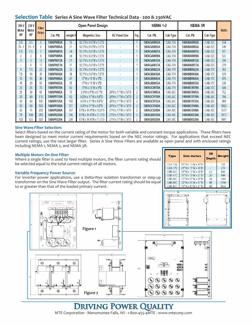
Sine Wave Filter Selection: Select filters based on the current rating of the motor for both variable and constant torque applications. These filters have been designed to meet motor current requirements based on the NEC motor ratings. For applications that exceed NEC current ratings, use the next larger filter. Series A Sine Wave Filters are available as open panel and with enclosed ratings including NEMA 1, NEMA 2, and NEMA 3R.
Multiple Motors On One Filter:Where a single filter is used to feed multiple motors, the filter current rating should be selected equal to the total current ratings of all motors.
Variable Frequency Power Source:For inverter power applications, use a Delta-Wye isolation transformer or step-up transformer on the Sine Wave Filter output. The filter current rating should be equal to or greater than that of the loaded primary current.
Selection Table Series A Sine Wave Filter Technical Data - 200 & 230VAC
Driving Power QualityMTE Corporation - Menomonee Falls, WI - 1-800-455-4MTE - www.mtecorp.com
Figure 2
Figure 1
Driving Power QualityMTE Corporation - Menomonee Falls, WI - 1-800-455-4MTE - www.mtecorp.com
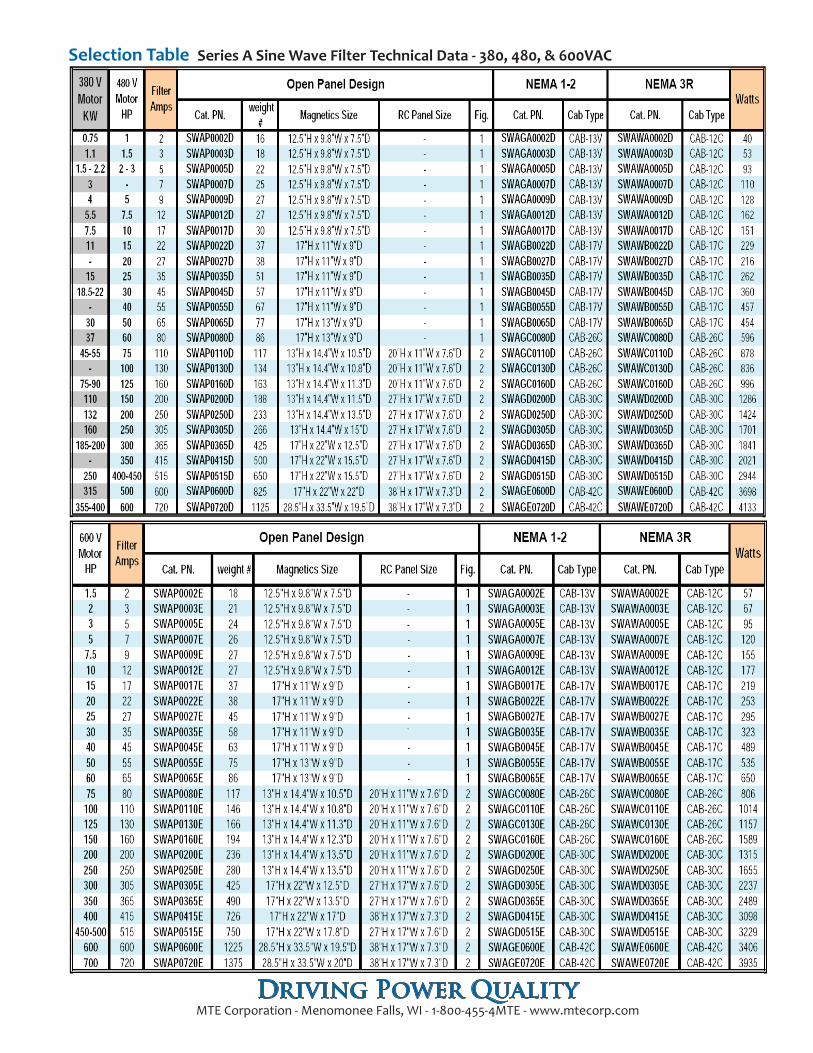
Selection Table Series A Sine Wave Filter Technical Data - 380, 480, & 600VAC
World HeadquartersN83 W13330 Leon RoadMenomonee FallsWisconsin 53051Toll Free 1-800-455-4MTEPhone: (262) 253-8200Fax: (262) 253-8222
For Technical Support: [email protected] Sales Support: [email protected]
Visit us on the Web at:www.mtecorp.comForm SW-PSL-E June 2012
© 2011 MTE CorporationAll Rights Reserved
®
Product Specifications - 2kHz-8kHz Sine Wave FiltersRefer to the Series A Sine Wave Filter User Manual for Detailed Specifications
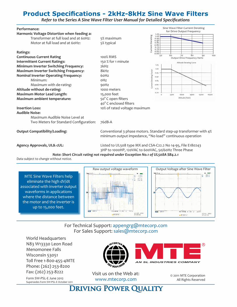
Performance:Harmonic Voltage Distortion when feeding a: Transformer at full load and at 60Hz: 5% maximum Motor at full load and at 60Hz: 5% typical
Ratings:Continuous Current Rating 100% RMSIntermittent Current Ratings: 150 % for 1 minuteMinimum Inverter Switching Frequency: 2kHzMaximum Inverter Switching Frequency: 8kHzNominal Inverter Operating Frequency: 60Hz Minimum: 0Hz Maximum with de-rating: 90HzAltitude without de-rating: 1000 metersMaximum Motor Lead Length: 15,000 feetMaximum ambient temperature: 50° C open filters 40° C enclosed filtersInsertion Loss: 10% of rated voltage maximum Audible Noise: Maximum Audible Noise Level at Two Meters for Standard Configuration: 76dB-A
Output Compatibility/Loading: Conventional 3 phase motors. Standard step-up transformer with 4% minimum output impedance, “No load” continuous operation
Agency Approvals, UL& cUL: Listed to UL508 type MX and CSA-C22.2 No 14-95, File E180243 3HP to 1000HP, 120VAC to 600VAC, 50/60Hz Three Phase
Note: Short Circuit rating not required under Exception No.1 of UL508A SB4.2.1
Sine Wave Filter Current Deratingfor Drive Output Frequency
0.600.650.700.750.800.850.900.951.001.05
50 60 70 80 90 100Output Drive Frequency Hertz
Curr
ent
Der
atin
g
Driving Power Quality
Raw output voltage waveform Output Voltage after Sine Wave Filter
Altitude Derating Curve
Curr
ent D
erat
ing
Fact
or
Altitude (Feet)
1.05
1.00
0.95
0.90
0.85
0.80
0.75
0.700 3300 6600 9900 13200 16500
MTE Sine Wave Filters help eliminate the high dV/dt
associated with inverter output waveforms in applications
where the distance between the motor and the inverter is
up to 15,000 feet.
Data subject to change without notice.
Supersedes Form SW-PSL-E October 2011