sincrotrone trieste - ilo - industrial liaison office
TRANSCRIPT

Sincrotrone Trieste
Elettra Laboratory

Product Catalog 2011
Release: SR11OctILO - October 2011
It is forbidden to reproduce this Catalogue, in whole or in part, without written authorisation from Sincro-trone Trieste S.C.p.A., who reserves the right to mod-ify its contents at any time without notice.
© Sincrotrone Trieste S.C.p.A. - 2011

THE ELETTRA LABORATORY
Elettra is a national laboratory managed by
Sincrotrone Trieste S.C.p.A, located in the
town of Basovizza at the outskirts of Trieste.
The mission of Sincrotrone Trieste is to provide
scientific services to the national and interna-
tional communities, through the development
and open use of light produced by synchrotron
and Free Electron Laser (FEL) sources.
The Elettra laboratory is based on the syn-
chrotron, a third generation electron storage
ring, optimized in the infrared , VUV (Vacuum
ultraviolet) and soft -X-ray range. The light is
made available through beamlines feeding
measuring station using different and comple-
mentary techniques ranging from analytical
microscopy and micro radiography to photon
lithography. More than 20 supporting laborato-
ries are available to users for experiments and
the staff is trained to assist the users, prepare
the set up and provide continuos maintenance
to the beamlines. The targeted operating time
of the synchrotron is 5000 hours/year provid-
ing 80,000 hours of user time on the individual
measurement stations. The beamlines and lab-
oratories are fully open to scientists at the na-
tional as well as international level for basic and
applied research in biology, physics, chemistry,
material sciences, medicine and environmental
studies.
FERMI, a new fourth generation FEL light
source just completed the commissioning
and will be soon open to users. It is a unique
source capable of producing very intense and
short flashes of light in the wavelength inter-
val between the far ultraviolet and x-ray.
The new light source will allow researchers to
explore further in space and time, following
the evolution of chemical reactions in the time
scale of a ten thousandth of a billionth of a
second and scanning matter of microscopic di-
mensions, down to a nanometre. It will be the
new frontier for basic and applied research.

The Industrial Liaison Office was set up in 2004 by
Sincrotrone Trieste S.C.p.A. to promote the use
of its facilities and know-how for applied research
and industrial purposes.
These technology transfer activities create impor-
tant supply and demand effects and stimulate a
strong industrial impact.
The collaboration with the Industry concerns:
• Analytical and metrological services in the
micro-nanoscale for chemical-physical and elec-
tronic structure of materials and devices: industry
pays the laboratories to provide dedicated meas-
urements selected among the available technolo-
gies, granting confidentiality of results and sup-
port in problem solving activities;
• Research and Development Projects: the
Elettra staff works with the industry using its
knowledge and the facilities for products and pro-
cess co-development;
TECHNOLOGY TRANSFER @ELETTRA
• Micro Fabrication: Photolithographic fabrica-
tion of microelectronic, optoelectronic, microme-
chanic and microfluidic devices;
• Design and Development of very advanced
scientific instrumentation for especially the con-
struction of new facilities or laboratory improve-
ments such as: accelerator components, scientific
instrumentation, customized software etc... ;
• Spin - Offs and New Business Development to
promote the use of patented scientific results
• Consulting and Training of industry personnel.
•
The Industrial Liaison Office support and coordi-
nates all Laboratory activities that are relevant for
industrial applications and has the capabilities to
sell products and services to other synchrotron
facilities and to supply advanced instrumentation
to private companies operating in different fields:
mechanics, optics, pharmaceutical, microelec-
tronics, energy, chemistry etc.

Power Supply Equipment
New families of intelligent (DSP or PC embedded) power supplies, that cover many typologies (high
voltage/current, four-quadrant etc.) and configurations are forthcoming. Epics or Tango interface
are often already present and custom-built solutions are possible.
Detectors
Photons and charged particles detectors, based on cross delay anodes, multi anodes and centroid
finding techniques are steadily developed. 3D information (x, y, time) with spatial and time resolutions
in the order of tens of microns and picoseconds are available through many custom-built solutions.
Lab Instruments
Several instruments necessary for typical or extreme applications are available: fast picoammeters,
multi-point strain gauge, charge pulse amplifiers, ion chambers, pulse generators, RF filters etc.
Every tool is intelligent and in some cases “Epics/Tango interface” is already provided.
Accelerator Parts
Elettra, over the years, has acquired great experience in developing and realizing accelerators compo-
nents, i.e. undulators, resonant cavities etc. For the production of Insertion Devices, a specific spin-off
company (Kyma S.r.l.) has been set-up, while other components will be provided directly by Elettra.
PRODUCT RANGE


Power Supply Equipment
MAS-TER Bipolar Power Supply System 8
HiSTAR Series Power Supply 10
A2505BS Low Voltage Bipolar current power Supply 12
Detectors
Photons and Charged Prticles 3D (x,y,z) Detectors 14
XBPM-DR1 X-ray Beam Position Monitor 16
FCB-001 Cavity Beam Position Monitor 18
BLM-IC02 Ionization Chamber Beam Loss Monitor 20
Lab Instruments
AH401 / AH401B Picoammeter 22
AH501 Picoammeter 24
AH501B Picoammeter 26
XPi Data Acquisition System 28
L01 DOSFET Reader 30
PIT-RFLN Wide Band Pulse Amplifier 32
RUD-RFLN XLS Pulse Amplifier 34
Accelerator Parts
Electromagnetic RF devices 36
3D magnetic structures 38
Chicane Bunch Lenght Compressors 40
Elettra Type RF Cavities and Accessories 42
Low Level RF Electronic Units 44
PRODUCT LIST

Power Supply Equipment
The MAS-TER system makes available
proprietary know-how that allows to
safely control, with the highest accuracy,
repeatability, resolution and stability, pi-
ezoelectric mirrors based on piezoelec-
tric ceramic bimorph actuators. Thus it
is the most reliable, efficient and power-
ful tool for controlling bimorph mirrors
in order to easily obtain their best per-
formances.
A main general purpose control unit su-
pervises all connected power supplies
modules and runs proprietary software
allowing complete control of the system
and assuring the communication with
any host computer via standard Eth-
ernet connection. The mechanical rack
(19” wide, 3U-high Euro-mechanics)
has an internal bus where the individual
modules are connected through multi-
polar connectors for both power supply
and data transfer.
The system can host up to 4 modules
(A4205D). Each module contains a 4
linear bipolar zero crossing channel
delivering 0.5mA@2kV, especially de-
signed to drive piezoelectric bendable
mirrors.
Powerful and versatile digitally controlled multichannel 2kV power supply system especially suited for applications in experimental physics
MAS-TER HV Bipolar Power Supply System
— 8 —

Power Supply Equipment
MAS-TER Specifications
Channels Up to 16 channels (4 channels/module)
Effective Output Current 500 mA
Effective Output Voltage ± 2000 V zero crossing
Data Transfer up to 1Mbit/s
Resolution 16 bit
Communication Modular (RS-232, USB, Ethernet TCP/IP and UDP)
Supply Voltage 90-240 Vac, 50-60 Hz, 60 W
Output Connectors Radiall SHV connectors
Dimensions 19” wide, 3U-high Euro-mechanics rack
Weight 6 kg (with 1 A4205D installed)
Block Diagram
Modular communication also satisfies us-
ers’ requests: RS232, USB and Ethernet
(TCP/IP and UDP) communication mod-
ules are available and are designed to
reach data transfer rates up to 1 Mbit/s.
The system is composed by a main con-
troller (C2808D) and up to four high volt-
age power supply modules (A4205D).
Each power supply module houses four
bipolar channels each capable of gener-
ating ±2kV.
Each channel of the A4205D module is
referred to ground. An additional PS0175
module provides the main power supply
to each A4205D module via a dedicated
internal power bus.
Each system controller is released with
a preloaded Windows XP OS kernel and
with a customized software application,
which handles the communication with all
connected modules.
— 9 —

Power Supply Equipment
Highly Stable and Reliable True Bipolar Current Power Supply
High efficiency, low cost, high stability, ease of installation and maintenance are the key features of this new power sup-ply, especially designed to operate in particle accelerator facilities.
The HiSTAR series implements a com-pletely digital PID control feedback loop that makes it extremely configurable and adaptive to any load condition. Its design, developed for high demanding Free Electron Laser (FEL) sources, offers extreme reliability and stability perfor-mances.
Up to 4 independent current modules can be housed in a single rack combined with an AC/DC converter (Service Power Sup-ply). In case of failure this modular ar-chitecture allows users to substitute only the faulty board.
The modules are provided with inde-pendent DSP/FPGA devices, supervis-ing all processes including the remote control of the power supply via an Eth-ernet connection (TCP/IP or UDP pro-tocol). 30 A module is also equipped with a local monitor controlled via an encoder and a graphic color display featuring user-friendly menus.
Each power supply channel has LED monitors for troubleshooting and an Ethernet 10/100 link for communica-tion.
Commercially available:
• 30 A - 20 Volt (A2630BS)
• 20 A - 20 Volt (A2620BS)
• 5 A - 10 Volt (A2605BS) modules.
HiSTAR Series Power Supply
— 10 —

Power Supply Equipment
Specifications A2605BS A2620BS A2630BS
Output Current Range ± 5 A ± 20 A ± 30 A
Output Voltage Range ± 10 V ± 20 V ± 20 V
Output Current Resolution 160 µA 640 µA 950 µA
DC/DC efficiency (at
full load)
> 90 % > 95 % > 95 %
Input Voltage 2 x 90/260 V AC (47/63 Hz)
90/260 V AC (47/63 Hz)
and 12 to 24 V DC
90/260 V AC (47/63 Hz)
and 12 to 24 V DC
Internal Interlocks under voltage (inp) over temp. (inp)
under voltage (inp) over temp. (inp) over current (inp) over voltage (out)
under voltage (inp) over temp. (inp) over current (inp) over voltage (out)
Earth fault Regulation fault/excess
current ripple
External Interlocks magn. fault (inp) PS status (out)
magnet fault (inp) PS status (out)
Bulk PS status (inp) Bulk PS ON/OFF (out)
8 user-configurable “dry“ contacts (inp) 2 magn. and 1 solid-state relay type (out)
Bandwidth-3dB (@2Ω load) 1.5 KHz
Accuracy 0.05 %
Long Term Stability ± 25 ppm /FS (>8 hrs)
Max Ripple 30 ppm (on resistive load)
Ethernet 10/100 TCP-IP or UDP Protocol
Data transfer up to 1Mbit/s
Drivers EPICS , TANGO
Dimensions 19” wide, 3U Rack
The storage of configuration and calibra-tion parameters in a non- volatile memory on the PB makes it extremely quick and simple, even for inexperienced users, to replace a faulty module with a working one.
Software and drivers are available for dif-ferent operating systems like MS Windows, Linux, Mac OS X; this device is also Epics- and Tango-compatible.
On high power modules the Power circuit houses a H-bridge output driver combined
with a 4th order LC- filter and also a high precision shunt resistor.
Applications:
• Particle accelerator facilities
• Medical Equipment (resonance imaging)
• Systems with high resolution courrent or voltage source requiremens
— 11 —

Power Supply Equipment
A2505BS Low Voltage Bipolar current power supply
Economic, stable, simple to install, analogic low voltage bipolar DC/DC current source power supply
The A2505BS is a low voltage bipolar DC/DC current source power supply. Economic, stable, simple to install and control, these are the most important benefits connected to its use in sinchro-tron light source reserch facilities.
Each DC/DC module is controlled by a 16 bit - 16 MHz microcontroller super-vising all processes. Users link serial communication, translated into either Ethernet or USB protocols by a small plug-in device mounted on a euro-card module, is provided.
A stand-alone software driver has been developed to control the power con-verter from a PC. This device is also compatible and can be easily control-
led via Epics and Tango global control systems.
The system has a modular design host-ed in a 19 inch 3U rack. Each power supply has a standard euro-card PCB format and 3U high - 10TE aluminium panel with five LEDs indicators for trou-bleshooting, a com socket and a rear bus connector for power and control. To speed up connections a rear backplane has been designed.
At maximum four modules can be housed in a single 3U-rack as part of the space is used for two AC/DC converters sup-plying rails.
The A2505BS has been widely used into the Booster pre-injector and demon-
— 12 —

Power Supply Equipment
A2505BS Specifications
Input Voltage Range 5/15 VDC
Max Input Current 7 ADC
Output Current Range -5/+5 ADC
Output Voltage Range -10/+10 VDC
Output Current Resolution 16 bit
Accuracy 100 ppm
Long Term Stability 100 ppm
Max Ripple 30 ppm
strates high reliability and stability over almost one year of operation.
Long term stability (> 8 hours) is better than 100 ppm/FS when variation of the ambient temperature is within ± 1 °C.
Output current is controlled by an analog feedback loop and the reference current is given by a D/A converter. A precise on board shunt resistor detects the output current and closes the loop. A MOSFet H bridge has been used as driver stage.
— 13 —

Detectors
Photons and charged particles 3D (x,y,t) detectors
Single counting photon/electron x-y detectors, able to correlate each count position with the time it was detected
A complete description of physical and chem-ical processes ideally requires atomic scale space resolution, pico or femtosecond scale time resolution, and meV energy resolution.
These results could be achieved by arranging an electron analyzer (or other instrumenta-tion able to give spatial/energetic informa-tion) with a detector suitable to provide time information.
In this perspective, two-dimensional detec-tors and a proper data acquisition system designed also to provide time resolved infor-mation, have been developed at Elettra.
They are “(cross) delay anodes” detectors, where the position is obtained through time
information, i.e. by calculating the time be-tween the start and stop signals coming from the anode ends, a feature that makes these systems intrinsically suitable for tim-ing information. “Time encoding” electronics is based on digital TDC that allows to count frequency up to 20 MCounts/s.
The delay line approach has several ad-vantages if compared with the other com-mon MCP based detection setups: differ-ently from CCD detectors it is a “single count” detector, which is an essential re-quirement in time resolved acquisitions; moreover, it is extremely linear, so that it does not introduce any distortion in the “image” obtained.
— 14 —

Detectors
Detectors Specifications
2-D detector size 30 × 30 mm2
90 × 20 mm2 with titanate substrate
50 × 50 mm2
2-D detector size, in “equivalent pixels” 30 × 30 mm2: 740 × 740
90 × 20 mm2: 2200 × 490
50 × 50 mm2: 2900 × 2900
Temporal resolution on the detector 27 ps
Temporal precision on the detector 40-50 ps
Corresponding spatial precision on the detector 60-70 μm
Max count rate in time resolved mode 4 Mcounts/sec
2D cross delay line detector: 50 X 50 mm2
Counts obtained in the direction perpendicu-lar to a blade put in close proximity to the detector.
Effect on the count-rate of a negative volt-age of 200 ns pulse applied to the grid (the lower figure is a zoom of the upper one). The system is able to detect in real time the con-sequent reduction of the number of electrons.
— 15 —
Detectors
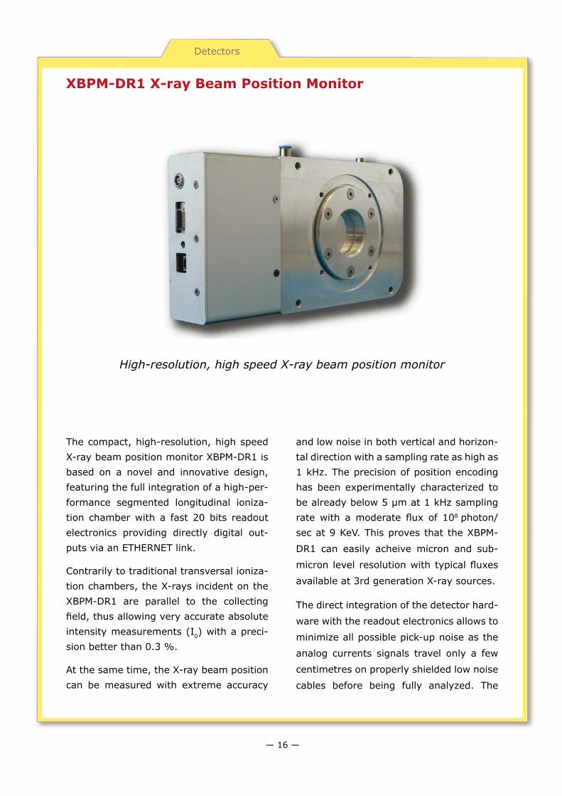
XBPM-DR1 X-ray Beam Position Monitor
The compact, high-resolution, high speed X-ray beam position monitor XBPM-DR1 is based on a novel and innovative design, featuring the full integration of a high-per-formance segmented longitudinal ioniza-tion chamber with a fast 20 bits readout electronics providing directly digital out-puts via an ETHERNET link.
Contrarily to traditional transversal ioniza-tion chambers, the X-rays incident on the XBPM-DR1 are parallel to the collecting field, thus allowing very accurate absolute intensity measurements (I0) with a preci-sion better than 0.3 %.
At the same time, the X-ray beam position can be measured with extreme accuracy
and low noise in both vertical and horizon-tal direction with a sampling rate as high as 1 kHz. The precision of position encoding has been experimentally characterized to be already below 5 µm at 1 kHz sampling rate with a moderate flux of 108 photon/sec at 9 KeV. This proves that the XBPM-
DR1 can easily acheive micron and sub-
micron level resolution with typical fluxes
available at 3rd generation X-ray sources.
The direct integration of the detector hard-
ware with the readout electronics allows to
minimize all possible pick-up noise as the
analog currents signals travel only a few
centimetres on properly shielded low noise
cables before being fully analyzed. The
High-resolution, high speed X-ray beam position monitor
— 16 —

Detectors
XBPM-DR1 is a totally integrated, stand-alone device and does not necessitate of any additional signal amplifier, converter or scaler unit.
The XBPM-DR1 is specifically designed for high flux synchrotron radiation experi-ments such as X-ray diffraction (protein, powder, small molecules…), EXAFS, fluo-rescence, X-ray imaging experiments, etc. using low or medium high X-ray energies [from 5 KeV to 40 KeV]. It is perfectly suit-able for all kinds of experiments requiring
precise and simultaneous I0 calibrations in the order of some % down to some ppm for quantitative measurements.
The analog readout has been particularly developed by ELETTRA and is directly con-nected to the digital part through a sealed feedthrough. The readout electronics per-forms state-of-the-art 20-bit currents measurements with integration times ranging from 1 ms to 1 s. Seven different gains can be set (from 50 pC to 350 pC full scale range) in order to adjust the op-timum working conditions to different ex-periments. An embedded microcontroller handles communication to the outer world via ETHERNET link. The input noise of the digital readout has been characterized to be 10 ppm srms at the highest gain for the typical input capacity of 200 pF of a quar-ter segment anode.
The ETHERNET High-Speed link allows
very fast data acquisition (currently up to
1 kHz) without significant dead time data
transfer. Optionally, a standard serial com-
munication port for longer distance data
transmission is also available.
XBPM-DR1 Specifications
Charge detection range from 50 to 350 pC
Resolution bits 20
Noise @ 1ms, 200pCFS <7 ppm
Integration time from 1 msec to 1 sec
Polarity Positive
Communication ETHERNET 10/100 bps
HV supply voltage 200 - 500 V
HV supply voltage stability Better than 1%
Output Channels 4
— 17 —

Detectors
FCB-001 Cavity Beam Position Monitor
The cavity Beam Position Monitor (C-
BPM) is an important beam diagnostic
instrument for a seeded FEL, since it al-
lows the measurements of the electron
beam trajectory in a non-destructive
way and with sub-micron resolution.
The high resolution cavity BPM relies on
the excitation of the dipole mode that is
originated when the bunch passes off-
axis in the cavity.
The C-BPM presented was developed for
the FERMI@Elettra facility. It is based
on an original implementation of the C-
BPM scheme as the pick-up, operating at
6.5GHz, is coupled to a dedicated, self-
calibrating electronics based on a novel
concept.
The detector electronics directly obtains
the envelope of sum and difference sig-
nals by means of an RF 180o hybrid; no
mixer for the RF signal down conversion
is used.
The detector is based on 3 blocks: an RF
front-end, a baseband analogue transmission
module and a digital back-end unit, based on
a μ-TCA platform and equipped with a pow-
erful Virtex 5 FPGA and several real-time
tasks including intra-pulse calibration.
Sub-micron resolution cavity Beam Position Monitor
— 18 —

Detectors
FCB-001 C-BPM Specifications
Cavity Gap 10 mm
Cavity Radius 26.29 mm
Beam Pipe Radius 10 mm
Coupling WG 30 × 6 mm
Distance WG to beam axis 19.39 mm
Resonant Frequency 6.5 GHz
Unloaded Q factor 7.900
External Q 75.000
Coupling Coefficient 0.1
C-BPM Pick-up. The pick-up consists of two mechanically tuneable copper cavi-ties with a 6.5 GHz resonance frequency.
One of these cavities generates the mo-nopolar component (reference signal), that is a damped sine wave at 6.5 GHz with a time constant t of approximate-ly 300 ns. The amplitude of the refer-ence signal is directly proportional to the charge. The second cavity generates two X and Y dipolar components on the four output connectors, two for vertical plane and two for horizontal plane (posi-tion signals). The amplitude of the posi-tion signal is directly proportional to the charge and to the distance of the beam from the cavity longitudinal axis.
A key feature is the amplitude of the output signal that goes to zero when the electron beam is on axis. The mechanical tuners fitted to each cavity on the C-BPM allow the alignment of three frequencies (reference, horizontal and vertical posi-tion) within 200 kHz around the nominal value of 6.5GHz.
Signal Detection. A custom hardware has been developed in order to directly detect the envelope of the RF signals pre-processed by an RF hybrid.
Position signals, phase shifted and am-plified, are combined with the reference signal in a 180° Double Arrow Hybrid Coupler. The hybrid coupler is a passive component performing both sum and dif-ference of its two input signals. These output signals pass through a digital 64 step attenuator. Besides, the amplitude envelope is measured by a precision RF Detector with 12 MHz baseband band-width.
Finally, the signals from the tunnel elec-tronics are acquired by the in-house developed 4 channel 160 Msps digitizer board (ADO), housed in the μ-TCA crate.
X axis envelope signals with 50pC off axis Beam.Ch1:envelope Σ signal, Ch2: envelope Δ signal
— 19 —

Detectors
BLM-IC02 Ionization Chamber Beam Loss Monitor
The BLM-IC02 ionization chamber, devel-oped for the FERMI@Elettra project, is an instrument particularly suited for beam loss monitoring in high energy particle ac-celerators.
Its high sensitivity facilitates the detection of electromagnetic showers of very low intensities, and its thickness of less than 5 cm allows an installation in tight spaces.
The chamber consists of three plane elec-trodes mounted inside a rugged aluminum enclosure. An externally supplied high voltage of up to 1000 V is applied between the outer electrodes and the central one.
Ionizing radiation creates free charges in the enclosed gas volume of 1.3 liters. As these charges are collected by the electrodes, a current among them can be measured with an extremely high ac-curacy.
Additional guard rings increase the ho-mogeneity of the electric field and limit leakage currents to less than 200 fA (at 1000 V).
The BLM-IC02 can be easily interfaced with the XPi data acquisition system or with the AH401B, AH501B picoamme-ters.
High sensitivity flat ionization chamber
— 20 —

Detectors
BLM - IC02 Specifications
Sensitivity (in air) 46 mC/Gy
Maximum Voltage 1000 V
Gas volume 1.3 l
Output connector BNC
HV connector SHV
Gas Inlet/Outlet 6 mm Swagelok® tube fittings
Weight 2700 g
Dimension 230 x 230 x 47.5 mm
Applications
• Beam Loss Monitoring
• Machine Protection
• Insertion Device Protection
• Radiation Dose Measurement
The chamber has a gas inlet and outlet to al-low the operation with a constant gas flux of typical detector gases like Argon or Nitrogen. Alternatively, it can work in air without need of an external gas supply.
Filled with air at standard atmospheric pres-sure, the sensitivity of the chamber amounts to 46 µC/Gy (in terms of generated charge per absorbed dose).
Due to its comparatively flat profile, the BLM-IC02 favors an orientation perpendicular to
00
100
50
1000400 600 800200voltage (V)
colle
ctio
n e
ffic
iency
(%
)
the direction of penetrating radiation. Secure mounting is made easy by several standard M6 screw threads.
ElectrodesGuard rings
Ion collection efficiency of the BLM-IC02 as a function of applied high voltage
Cross section of the BLM-IC02 showing the three main electrodes and additional guard rings
— 21 —

Lab Instruments
AH401 / AH401B Picoammeter
The AH401/AH401B picoammeter is a
4-channel, 20-bit resolution, low noise
instrument. It is composed by a partic-
ular charge-integration input stage for
low-current sensing combined with a 20-
bit sigma-delta ADC converter integrat-
ing a noise reduction digital filter.
This device performs current measure-
ment from 50 pA (with a resolution of 50
aA) up to 1.8 µA (resolution of 1.8 pA),
with integration time ranging from 1ms
up to 1s. Moreover each input channel
has two integrator stages so that the
current-to-voltage conversion can be
performed continuously during the ADC
conversion avoiding any dead time in the
data output.
The AH401/AH401B is housed in a light
and extremely compact box that can be
placed close to the signal sources in or-
der to reduce cable lengths and minimize
possible noise pick-up. It is particularly
suited for applications where multi-chan-
nel simultaneous acquisition is required,
i.e. 4-quadrant photodiodes for beam
displacement measurements.
Low temperature drifts, good linearity
and very low noise allow to obtain high-
precision current measurements.
Stand-alone 20 bit, charge-integration based, 4-channels
low noise digital picoammeter
— 22 —

Lab Instruments
Picoammeter main specifications
Input channels 4
Input connectors type BNC
Effective current measuring range From 50 pA to 1.8 mA
Resolution bits 20
Data transfer Up to 1 ksamples/sec
Integration time from 1 msec to 1 sec
Polarity Positive
Communication (AH401) USB 2.0
Communication modules (AH401B) USB 2.0, RS-232/422/485, Ethernet TCP-IP/UDP
I/O Signal (AH401B) CONV output - TRIGGER/GATE input
Supply voltage from 9 V to 15 V
Supply current from 100 to 35 0 mA depending on comm. module
Dimensions 140 x 110 x 28 mm
Weight 420 g
The picoammeter can be easily controlled via communication interface: integration time, range, data format, type of acquisi-tion, baudrate and a lot of other param-eters can be instantly set and checked.
The AH401 has a fixed high speed USB in-terface working only with dedicated Lab-View™ USB driver under Windows™ OS. A LabView™ simple program, showing basic acquisition mode and interface commands, is supplied with the device.
Conversely, the AH401B with its modular communication capability allows the user
to choose the type of interface needed leaving the flexibility into controlling the device with different types of program-ming languages and/or operating systems. Available modules are: RS232, RS422/485, USB and Ethernet (TCP/IP and UDP).
Acquisition of samples from the AH401/AH401B can be performed either using “continuous” or “on demand” transmission modes:
- “continuous” mode: data are continu-ously sampled and transmitted, without external intervention, to the host device, allowing real time data acquisition;
- “on demand” mode: data are sampled and transmitted only on specific remote command request.
On the AH401B an external TRIGGER/GATE input signal is available to synchro-nize the acquisition of the picoammeter with external events (i.e. laser trigger-ing). Furthermore, digital samples can be transferred either using ASCII format or RAW binary data format for fast data transmission.
Block Diagram
Communication
— 23 —

Lab Instruments
AH501 Picoammeter
AH501 picoammeter is a 4-channel, 24-bit
resolution, wide bandwidth, ultra wide in-
put dynamic range, feedback-type instru-
ment. It is composed by a particular tran-
simpedance input stage for current sensing
combined with several analog signal condi-
tioning and filtering stages with state-of-
the-art electronics.
This device performs current measurement
from ±2.5 nA (with a resolution of 298 aA)
up to ±11 mA (resolution of 1.35 nA) with
sampling frequencies up to 26 kHz (for 1
channel and a 16-bit resolution) and 6,5
kHz (4 channels, 16 bit/sample). AH501
is light, compact and extremely versatile
and it is especially suited for applications
where multi-channel fast acquisition is a
concern, i.e. feedback systems. Low tem-
perature drifts, good linearity and very low
noise allow to obtain high-precision current
measurements.
Modular communication also satisfies cus-
tomer requests: xPiggy modules as RS-
232Piggy, USBPiggy and EtherPiggy (TCP/IP
and UDP) are thought to reach data transfer
rates up to 1 Mbit/s. AH501 is already run-
ning in Elettra GOF (Global Orbit Feedback),
a project on the gap-monitor photon BPMs
of ALOISA beamline and it is ready to be in-
stalled on several other beamlines.
Stand-alone 24 bit, 26 ksample/sec, 4-channels, low noise and wide dynamic range digital picoammeter
— 24 —

Lab Instruments
Picoammeter main specifications
Input channels 4
Input connectors type SMA or BNC
Effective current measuring range From ± 2.5 nA to ± 11 mA
Resolution bits 16 or 24
Data transfer Up to 26 ksamples/sec (1 ch. 16 bit)
Analog cut-off Configurable (tested up to 10 kHz)
Polarity Bipolar
Communication modules USB 2.0, R-S232, Ethernet TCP-IP and UDP
Supply voltage from ± 6 V to ± 9 V
Supply current from 270 to 410 mA depending on comm. module
Dimensions 160 x 108 x 45 mm
Weight 500 g
AH501 is available in different configura-tions: analog cut-off frequency (standard value is 1 kHz but it has been successfully tested up to 10 kHz), communication inter-face (xPiggy) and input connectors (SMA or BNC) are configurable on request.
The availability of trigger input and output signals on a RJ11 connector allows the ac-quisition sincronization to external events.
The picoammeter can be easily controlled using a xPiggy module: resolution, gain, data format, number of channels, baudrate and many other parameters can be instantly
checked and set, with handling times for the request to be executed of a few tens of µs.
Acquisition of samples from the AH501 can be performed either using continuous or “on demand” transmission mode:
• continuous mode: data are continuously sampled and transmitted to user’s host de-vice;
• on demand mode: data are sampled and transmitted only at certain times, whenever a generic host device sends a specific re-quest (‘g’ and ‘get ?’ commands).
The “on demand” mode can be used by a remote system to send requests up to once every 250 µs (1 channel, 16 bit/sample) and it is useful for applications where a reliable synchronization with binary data (sent in continuous mode) could be a difficult task.
Digital samples can be transferred either us-ing ASCII format or RAW binary data for-mat.
GOF at Elettra is currently acquiring data in binary format using the “on demand” mode, with data requests that are sent to the AH501 every 400 µs, for a 2.5 kHz sampling rate (4 channels, 24 bit/sample resolution).
Block Diagram
Main Features
— 25 —

Lab Instruments
AH501B Picoammeter
The AH501B picoammeter is a 4-channel,
24-bit resolution, wide bandwidth, ultra
wide input dynamic range, feedback-type
instrument with analog outputs and bias
voltage. It is composed of a special tran-
simpedance input stage for current sensing
combined with several analog signal condi-
tioning and filtering stages with state-of-
the-art electronics.
This device performs current measure-
ments from ±2.5 nA (with a resolution
of 298 aA) up to ±2.5 mA (resolution of
298 nA) with sampling frequencies up to
26 kHz (for 1 channel and a 16-bit resolu-
tion) and 6.5 kHz (4 channels, 16 bit/sam-
ple). The AH501B is light, compact and ex-
tremely versatile and it is especially suited
for applications where multi-channel fast
acquisition is a concern, i.e. feedback sys-
tems. Low temperature drifts, good linear-
ity and very low noise allow to obtain high-
precision current measurements. Data are
transferred through TCP/IP or UDP com-
munication. Data transfer rates up to 1
Mbit/s is achievable.
The picoammeter is provided of 4 analog
output +/- 5 Volts for current analogue
measurements. An additional 0 - 30 Volt
bias output is available for detector polari-
zation.
Stand-alone 24 bit, 26 ksample/sec, 4-channels, low noise and wide dynamic range digital picoammeter with analog outputs and bias voltage
— 26 —

Lab Instruments
Picoammeter main specifications
Input channels 4
Input connector type BNC (SMA on request)
Effective current measuring range From ± 2.5 nA to ± 2.5 mA
Resolution bits 16 or 24
Analog output range ± 5 V
Bias voltage 0-30 V
Output connector type SMA
Data transfer Up to 26 ksamples/sec (1 ch. 16 bit)
Analog cut-off Configurable (tested up to 10 kHz)
Polarity Bipolar
Communication modules Ethernet TCP-IP and UDP
Supply voltage from ± 6 V to ± 9 V
Supply current 350 mA
Dimensions 160 x 108 x 45 mm
Weight 500 g
The AH501B is available in different configura-tions: analog cut-off frequency (standard value is 1 kHz but it has been successfully tested up to 10 kHz), and input connectors (SMA or BNC) are configurable on request.
The availability of trigger input and output sig-nals on BNC connectors allows the acquisition sincronization to external events.
The picoammeter can be easily controlled by remote: resolution, gain, data format, number of channels, baudrate and many other param-eters can be instantly checked and set, with handling times for the request to be executed of a few tens of µs.
Acquisition of samples from the AH501B can be performed either using continuous or “on de-mand” transmission mode:
• continuous mode: data are continuously sampled and transmitted to user’s host device;
• on demand mode: data are sampled and transmitted only at certain times, whenever a generic host device sends a specific request (‘g’ and ‘get ?’ commands).
The “on demand” mode can be used by a re-mote system to send requests up to once every 250 µs (1 channel, 16 bit/sample) and it is use-ful for applications where a reliable synchro-nization with binary data (sent in continuous mode) could be a difficult task.
Digital samples can be transferred either using ASCII format or RAW binary data format.
Block Diagram
Main Features
— 27 —

Lab Instruments
XPi Data Acquisition System
The XPi data acquisition system, conceived for the FERMI@Elettra project, is a new modular controller particularly suited for beam diagnostic devices like ion-chambers and beam position monitors. It is a system that can be equipped with ad-hoc modules according to the device controlled.
Currently available modules are a fast 4-channel, low noise charge integration picoammeter and an ultra low noise high-voltage module.
The controller has several external input/output optical TRIGGER and CONVER-SION signals useful for data acquisition synchronization with external events like
Lasers or FEL pulses. The system is also equipped with an output switch contact for interlock systems.
The XPi Controller includes an LCD display for direct data readings and a manual con-trol to configure the main device parame-ters. Moreover, the system can be remote-ly controlled through the installed standard 10/100 Ethernet interface. Instrument communication TCP/IP or UDP protocols can be selected (TANGO device driver and LabVIEW VIs are available on request).
The whole system is housed in a compact 1U 19” standard rack and is directly pow-ered from the 110/220V main supply.
Modular acquisition system for beam diagnostics
— 28 —

Lab Instruments
XPi Data Acquisition System main specifications
Instrument module slots 2
External I/O Optical TRIGGER and CONVERSION signals
Interlock interface 2 SPDT Switch type
Front panel display LCD 4 row x 20 char
Communication Ethernet TCP-IP and UDP
Supply voltage 110V/220V - 50/60 Hz
Dimensions 1U 19” Rack - 482 x 260 x 44 mm
Weight 3600 g
XPi Picoammeter XPi HV
Input Channels 4 Output Channels 1 HV + 1 monitor
Charge meas. range 50pC - 1.8 nC Resolution Bits 16
Effective current range 50 pA - 3.6 mA Output Connectors SHV + BNC
Resolution Bits 20 Noise (for 1 KV) RMS Typ. < 500 mV @600V
Integration Time 500 msec - 1 sec HV fixed Voltages from ± 200 to ± 2000
Polarity Positive Output Power 1 W
The XPi data acquisition system can be equipped with ad-hoc modules for instru-ment control. Available modules are:
XPi Picoammeter. A fast 4-channel, simul-taneous sampling, 20-bit resolution, low noise, charge integration picoammeter. The module performs triggerable charge meas-urement ranging from 50 pC (with a resolu-tion of 50 aC) up to 1.8 nC (with a resolution of 1.8 fC). With a software programmable integration-time starting from 500µs up to 1s, a current measurement ranging from 50 pA (resolution of 50 aA) up to 3.6µA (resolution of 3.6 pA) is achievable. Each input channel has two integrator stages, so that the current-to-voltage conversion can be continuously performed during the ADC conversion avoiding any dead time in the data output.
XPi HV. An ultra-low noise, high-stability, 16-bit resolution, high-voltage module pro-vides output voltages from +/-200V (with
a minimum step increment of 3 mV) up to +/-2000 V (with a minimum step increment of 30.5 mV) and it is especially suitable for ion-chambers or other detector polarization.
Applications
• Fast Feedback applications• 4-quadrant beam position monitor• Ion Chamber flux monitoring• Photodiode acquisition• Precision process control• Multichannel charge/current acquisition• Direct current measurement• Detector polarization
XPi HV and Picoammeter Modules
— 29 —

Lab Instruments
L01 DOSFET Reader
The L01-DOSFET Reader, developed for the FERMI@Elettra project, is a complete readout solution for a wide range of elec-tronic MOSFET dosimeters.
It is well known that MOSFETs are sus-ceptible to ionizing radiation. The main reason for this is the insulating oxide layer separating the gate electrode from the semiconductor. Under irradiation, electrons are removed from this layer and leave behind a positively charged region.
Due to the good insulating properties of the oxide, only little recombination takes place. Hence, the positive charges can
remain trapped in the oxide layer for many years. This positive space charge screens the electric potential of the gate electrode and thus changes the electrical characteristics of the transistor.
The L01-DOSFET Reader measures this change by injecting a constant current of 490 µA between the source and the drain electrodes.
The voltage needed to drive this current is a measure of the total ionizing dose the MOSFET has received. It typically ranges from few volts for an unirradiated dosim-eter to more than 10 V for one that has been exposed to a dose of several kGy.
Complete readout solution for electronic MOSFET dosimeters
— 30 —

Lab Instruments
L01-DOSFET Reader main specifications
Input readout channels 4
Readout voltage up to 25 V
Resolution bits 24
Readout period minimum 10 sec
Readout current 490 mA
Communication Ethernet TCP-IP
Interlock output potential free contact
Form factor 19”
Dimensions 1U 19” Rack - 482 x 260 x 44 mm
Weight 2500 g
Periodic readout and irradiation bias. The L01-DOSFET Reader autonomously performs a readout of all connected dosimeters when switched on. It then continuously repeats the measurement with an adjustable period of time. In the pauses between measurements, the electrodes of the dosimeters are kept at ground potential.
This means that, connected to the Reader or not, the MOSFETs accumulate charge from ir-radiation in the same way. The dosimeters can hence be used even in places that are diffi-cult to access, performing an “offline” readout later.
The L01-DOSFET Reader can be customized on request to supply a positive voltage could be applied during irradiation between the gate electrode on the one side and the drain and source electrodes on the other side. This en-hances the sensitivity of the dosimeter, but requires the bias voltage to be present at all times.
Ethernet connectivity and software. The Reader is equipped with a fully configurable Ethernet interface and can easily be integrated into an existing LAN. A complete data logging application is available in source code (C++)
and can be used as a starting point for custom developments. On request, a complete server environment for the Tango control system can be provided.
MOSFET dosimeter monitoring undulators
Connecting the dosimeters. The Reader uses standard USB cables to connect the do-simeters. If the dosimeters should not be sol-dered directly to the cable, a customized hold-er is needed to interface the MOSFET to the cable and to facilitate mounting. On request, prefabricated holders can be provided.
— 31 —

Lab Instruments
PIT-RFLN Wide Bandwidth Pulse Amplifier
The RF low noise and wide bandwidth amplifier has been expressly developed to deal with typical pulses generated on MCP or channeltron detectors.
The advanced silicon technology em-ployed grants high dynamic range and low noise figure needed to amplify puls-es whose rise and fall time is lower than 4 ns (see technical specifications o the other side).
The instrument is provided with in/out 50 Ohm connectors compliant to stand-ard systems, in particular with delay lines (wires or strip lines) where the 50
Ohm matching is needed.
The preamplifier is hosted in a mechani-cal box that properly screens its elec-tronics from external perturbation.
Besides, a modified version of this
amplifier, to be used with detectors
generating extremely low intensity
pulses, has been developed. Further
information on this product is availa-
ble on RUD-RFLN-XLS Pulse Amplifier
data sheet.
All used components for Pulse Ampli-
fier are RoHS compliance certified.
RF low noise wide bandwidth amplifier optimized for pulses generated on MCP and channeltron detectors
— 32 —

Lab Instruments
Pulse Amplifier Specifications
Band -3dB 35kHz: 1GHz
Gain @ 2GHz 34 dB
Gain @ 3GHz 31 dB
Gain @ 4GHz 27 dB
Gain @ 5GHz 22 dB
Gain @ 6GHz 18 dB
Gain @ 7GHz 16 dB
Gain @ 8GHz 11 dB
Noise 2.7 dB
Power Supply 15 V
Current 38 mA
Max in RF 13 dBm
Out 1dB comp 2.8 dBm @ 2 GHz
Out IP3 18 dBm @ 2 GHz
Z in 50 Ω
Z out 50 Ω
Square wave: ch1 = Input ch2 = Output 50 ns/div
Pulse: ch1 = Input ch2 = Output 2 ns/div
Fall Time: ch1 = Input ch2 = Output 2 ns/div
Marker Frequency 150 MHz F=2.16 dB Teff=186 K
Frequency response–range: from 100 kHz to 2 GHz
Measurement set-up
— 33 —
Lab Instruments
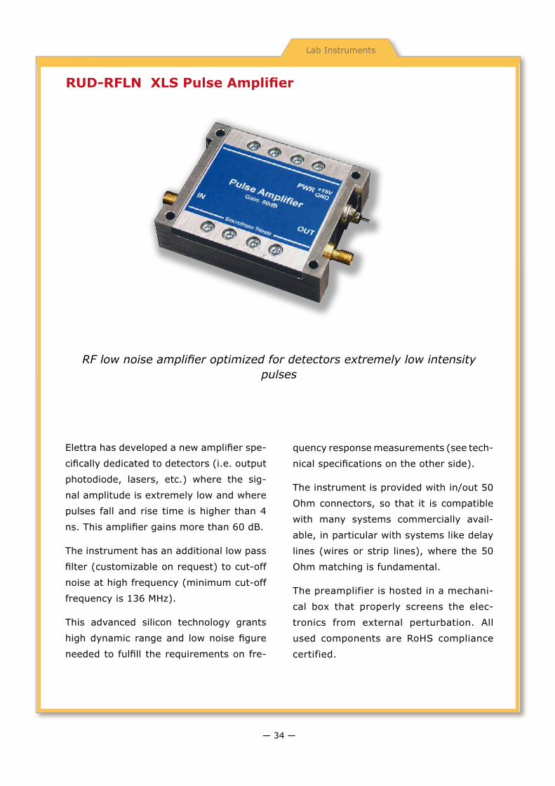
RUD-RFLN XLS Pulse Amplifier
Elettra has developed a new amplifier spe-
cifically dedicated to detectors (i.e. output
photodiode, lasers, etc.) where the sig-
nal amplitude is extremely low and where
pulses fall and rise time is higher than 4
ns. This amplifier gains more than 60 dB.
The instrument has an additional low pass
filter (customizable on request) to cut-off
noise at high frequency (minimum cut-off
frequency is 136 MHz).
This advanced silicon technology grants
high dynamic range and low noise figure
needed to fulfill the requirements on fre-
quency response measurements (see tech-
nical specifications on the other side).
The instrument is provided with in/out 50
Ohm connectors, so that it is compatible
with many systems commercially avail-
able, in particular with systems like delay
lines (wires or strip lines), where the 50
Ohm matching is fundamental.
The preamplifier is hosted in a mechani-
cal box that properly screens the elec-
tronics from external perturbation. All
used components are RoHS compliance
certified.
RF low noise amplifier optimized for detectors extremely low intensity pulses
— 34 —

Lab Instruments
Pulse Amplifier Specifications
Band -3dB 35 kHz: 130 MHz
Gain @ 50 MHz 61 dB
Gain @ 130 MHz 58 dB
Noise 1.8 dB
Power Supply 15 V
Current 60 mA
Max in RF 13 dBm
Z in 50 Ω
Z out 50 Ω
Low pass filter 80 MHz @ -1 dB
130 MHz @ -3 dB
Low pass filter Customizable
Square wave: ch1 = Input ch2 = Output 50 ns/div
Pulse: ch1 = Input ch2 = Output 2 ns/div
Fall Time: ch1 = Input ch2 = Output 2 ns/div
Rise Time: ch1 = Input ch2 = Output 2 ns/div
Frequency response–range: from 100 kHz to 500 MHz
Measurement set-up
61 dB
4 ns
Marker Frequency 211 MHz F=1.78 dB Teff=147 K
— 35 —

Accelerator Parts
Electromagnetic RF devices
The use of simulation codes has proved to be of fundamental importance for the design and study of RF and microwave components. These computational tools allow the design of complex RF struc-tures on the computer minimizing cut-and-try optimization methods as well as expensive model building for cold meas-urements.
The Radiofrequency Group of Sincrotrone Trieste uses 2D and 3 D simulation codes that allow frequency domain and time domain calculations in the RF and micro-wave range.
Expertise in mastering such tools has been acquired during the design of RF
systems components and other equip-ment for Elettra and other facilities.
Examples of these applications are:
• Resonant structures like RF cavities;
• Modelling of couplers and pick-ups;
• Study of tapers and beam position monitors;
• Modelling of waveguides and RF Power Transitions.
These tools have been also used to design RF and microwave structures for other in-dustrial applications.
The Radiofrequency Laboratory of Sincro-trone Trieste is equipped with high preci-sion instrumentation (up to 20 GHz) for the measurement and test of RF and mi-crowave components.
Development, in frequency and time domain, of complex RF and microwave structures for custom applications
— 36 —

Accelerator Parts
Cavity power coupler modelling Study of power coupling problems
Study of cavity and taper problems
Beam Position Monitors modelling
Study of electromagnetic coupling
Investigations on thermal behaviour Couplers and pick-ups
Applications Examples
— 37 —

Accelerator Parts
3D magnetic structures
Electromagnets and more generally magnetic structures have been used to guide and manipulate charged particle beams in accelerators.
Using software packages to study and simulate 3D magnetic structures, at the design stage, has become a mandatory task when stringent parameters of the beam optics must be achieved as well as expensive model building for test and measurements.
Nowadays, these software tools allow 3D design of accelerator electromagnets with a high degree of accuracy. The result is a very high level of confidence in prediction.
Sincrotrone Trieste uses 3D modelling software to design and optimize electro-magnets to be used in accelerators lat-tices; this package is extremely useful in optimizing the poles profile and has been extensively used for the design and optimization of all magnets installed in the new FERMI@Elettra facility.
These tools have also been used to de-sign magnetic structures for other in-dustrial applications.
Sincrotrone Trieste is equipped with high precision instrumentation for the meas-urement and test of designed magnetic components.
Development, study and simulation of 3D magnetic structures for custom applications
— 38 —

Accelerator Parts
Delay Line dipole developed for the FERMI@Elettra project
Photo-gun spectrometer dipole of the FERMI@Elettra project
Quadrupole magnetic field
Magnetic field in a triplet quadrupole magnet
Corrector magnets for the FERMI@Elettra project
Booster dipole magnetic fieldMesh optimization for beam trajectory tracking in a dipole
of the FERMI@Elettra project
Applications Examples
— 39 —

Accelerator Parts
Chicane Bunch Lenght Compressors
In order to obtain the maximum effect dur-
ing seeding process, a seeded Free Elec-
tron Laser needs to operate with the lon-
gitudinally compressed electron bunches.
FERMI@Elettra operates with two bunch
compressors (BC). Each magnetic chicane
used for bunch length compression is made
of four identical dipole magnets powered by
a single power supply and two “tweaker”
quadrupoles sitting in the chicane side arms.
The needed diagnostics is mounted on the
chicane central drift. The two BC inner di-
poles are moveable on parallel rails orthogo-
nal to the central drift to accommodate dif-
ferent chicane bending angles in such a way
that the electron bunch stays centered on
the vacuum chamber axis.
The “tweaker” quadrupoles in the BC arms
also move transversally on rails parallel to
the inner dipoles rails. In order to keep
the electron beam centered independent-
ly of the chicane position the quadrupoles
have to be rotated. To compensate dipole
field differences between dipole magnets,
each magnet is equipped with an indepen-
dently supplied trim coil.
Design and development of magnetic chicane for bunch length compression in seeded Free Electron Lasers
— 40 —

Accelerator Parts
Since the RF photocathode gun produces up to 0.8 nC distributed over a bunch length of 10 ps, the bunch has to be compressed by a total factor of about 10 before it enters the undulator.
The acceleration and compression is done in the main S-band linac. The two bunch com-pressors consist of symmetric magnetic chi-canes, each 8.0 m long. They also include
trim quadrupoles for a fine tuning of the dis-persion bump.
The location and compression factor of the two chicanes are fixed in order to minimize the 6-dimensional emittance dilution of the electron bunch in presence of space charge
forces and wake fields. The nominal electron energy at BC1 is 320 MeV.
This feature avoids space charge effects, while compressing the bunch early enough in the linac to reduce the effects of transverse wake fields.
The nominal energy of the second com-pressor (BC2) is 670 MeV, which balances
the conflicting requirements of minimizing the transverse and longitudinal emittance dilution by coherent synchrotron radiation and canceling out the final correlated en-ergy spread by means of downstream lon-gitudinal wakes.
Bunch Compressors main magnetic specifications
BC1 BC2
Nominal Energy 320 MeV 670 MeV
Number of Dipoles 4 4
Curvature angle 0.07 rad 0.08 rad
Curvature radius 7.113 m 5.914 m
Magnetic field at center (nominal energy) 0.117 T 0.333 T
Bunch Compressors main mechanical specifications
Bending angle range 0-7 deg
Central drift displacement range 0-367 mm
First bunch compressor of the FERMI@Elettra Free Electro Laser
— 41 —

Accelerator Parts
Elettra Type RF Cavities and Accessories
Project and design of radiofrequency (RF) cavities for synchrotron light sources Storage rings and Boosters
Radiofrequency (RF) cavities provide the accelerating voltage and power to accel-erate and keep the beam in a Booster or Storage Ring.
The cavity developed at Elettra is a single cell cavity made of high purity (99.99%), high conductivity and oxygen free copper, designed to operate in a Ultra High Vacu-um (UHV) environment.
The internal profile of the cavity is made up of quarters of ellipse. This profile is op-timised to avoid multipacting phenomena and to reduce the amount of Higher Order Modes (HOM) trapped inside the cavity.
Effect of trapped HOM on the beam can
be cured by HOM Frequency Shifting Tech-niques based on fine temperature tuning and a dedicated plunger.
Radiofrequency power is fed to the cavity via an input power coupler of coaxial type, designed to operate in a UHV environment. The coupling coefficient can be adjusted simply by rotating the coupler.
A set of pick-ups (inductive and capacitive) is provided to monitor the RF fields inside the cavity for low level control electronics and measurements purposes.
Cavity and coupler are water cooled. A dedicated cooling rack for the cavity can be provided. This system, besides extract-
— 42 —

Accelerator Parts
ing the RF power dissipated in the cavity, allows a tight regulation of the external surface temperature in a wide range. Typi-cal cavity temperature stability of ±0.05 °C in a temperature range from 35 to 80 °C can be achieved.
The Radiofrequency Laboratory of Sincro-trone Trieste is equipped with simulator codes and high precision instrumentation for the design, measurement and test of RF and microwave components. A 500 MHz 60 kW cw power plant is available for cavi-ties and components power tests.
Even though Elettra type cavities have been developed for the Elettra synchrotron light source, they have been requested by many other machines. Now they are used for the main RF system at:
• Elettra (499.654 MHz) storage ring
• ANKA booster and storage ring (499.652 MHz)
• SLS booster and storage ring (499.652 MHz)
• Laboratorio Nacional de Luz Sincrotron (Campi-nas Brasil) booster and storage ring (476 MHz)
• INDUS II storage ring (506 MHz).
Installed Cavities
500 MHz Elettra Type Cavities typical specifications
Resonating Frequency 500 MHz
Shunt Impedance > 3.3 MΩ
Quality Factor > 39 000
Peak accelerating voltage 650 kV
Power wasted in the cavity < 65 kW
Maximum Power through the coupler 120 kW
Cooling Rack
RF Power Coupler
— 43 —

Accelerator Parts
Low Level RF Electronic Units
Specially designed tools to monitor amplitude and phase of RF field in storage ring cavities
The Low Level Electronics System has been specifically designed for control, regulation and monitoring of the amplitude and phase of RF fields in a cavity installed in a storage ring system.
Typically such high Q cavities (Q0 around 40000) are operated at power levels from tens to hundreds of kW with gap voltage up to hundreds of kV.
The modular design allows separate im-plementation of each unit and the possibil-ity of some customization to suit specific needs. The units are mounted in 19” 3U or 6U.
The Radiofrequency Laboratory of Sincro-
trone Trieste is equipped with simulator codes and high precision instrumentation for design, measurement and test of RF and microwave components.
The following modules are available:
• Frequency loop
• Amplitude loop
• Phase loop
• RF switch
• Mechanical Phase shifter
• Amplitude measurement
• Phase measurement
— 44 —

Accelerator Parts
Frequency Loop. It keeps a resonant cavity tuned, compensating for the reactive part of electron beam loading in the ring and for power and temperature effects. It works as a closed loop driving the motor of the mechanical tuning system of the cavity so that the required cavity frequency is maintained. The possibility to offset cavity and generator frequencies is foreseen.
Sensitivity ±100/±500/
±1000 Hz
Nominal Speed 700 Hz / sec
Open Loop 3 dB bw 200 Hz
Dynamic Range 20 dB
Amplitude Loop. It maintains RF voltage in a cavity stable in a ± 1 % range counteracting the resistive part of the beam loading through the entire operating range of electron beam current and energy. The loop controls the driving signal to the power amplifier according to the detected cavity voltage signal. Loop bandwidth can be selected to fit the needs.
Precision ±1%
Open Loop 3 dB bw up to 4 kHz
Recovery Time < 10 msec
Dynamic Range 20 dB
Phase Loop. It compensates for phase changes in the RF plant due to the power components and driving electronics. Loop bandwidth can be selected to fit the needs.
Precision ±1% for ±30°
Open Loop 3 dB bw up to 5 kHz
Dynamic Range 10 dB
RF Switch. This unit contains a fast RF switch and its controlling electronics. The fast RF coax-ial switch is used to allow the application of the driving signal to an RF plant and can be driven by the interlock signals for safety and protec-tion or by an operator. The switch used is a high isolation, absorptive, pin diode switch.
Switching Speed < μsec
Isolation 80 dB
Frequency 500 ± 10 MHz
Max RF input power 20 dBm
Mechanical Phase Shifter. This unit is a motor-ized phase shifter capable to provide a total phase variation of 500° at 500 MHz. The unit can be remotely driven.
Phase Shift 500° @ 500 MHz
Resolution 1° @ 500 MHz
Max Insertion Losses 3.3 dB
Max input power 50 W
Amplitude Measurement. This unit provides DC analog measurements proportional to the RF signals coming from RF detectors. Each board can provide up to 4 DC measurements.
Output Voltage 0-10 V
Output Impedance < 50 Ω
Accuracy < 2%
Dynamic Range 20 dB
Max Input Power 20 dBm
Phase Measurement. This unit measures phase differences of ±180° between two RF signals at the same frequency (optimized for 500 MHz). It is realized with two electronic boards: the “RF” board, which assembles an-alogical parts (mixer, PLL, RF amplifiers, com-parators, etc.), and the “Digital” board where the analog to digital conversion of the signals at the output of the “RF” board is performed. To have a linear output signal, the numerical values obtained via the converters, are ad-justed using the data stored into the memory placed on the board. Before being provided at the output, the digital signal is converted to an analog one.
Output at 500 MHz ±10 V for ±180°
Output Impedance < 50 Ω
Bandwidth > 20 kHz
Accuracy < 2°
Resolution < 1°
Max Input Power 20 dBm
— 45 —

CONTACTS
Sincrotrone Trieste S.C.p.A
in Area Science Park,
Basovizza S.S. 14, km 163,5
34149 Trieste ITALY
www.elettra.trieste.it
e-mail: [email protected]
Industrial Liaison Office:
ilo.elettra.trieste.it
tel. +39.040.375 8303
fax +39.040.375 8623
e-mail: [email protected]

