simultaneous multi-objective locating and sizing of ... · pdf filea major share of losses ......
TRANSCRIPT

Applied mathematics in Engineering, Management and Technology 2 (4) 2014:304- 315
www.amiemt-journal.com
304
Abstract
Today, application of shunt capacitors and distributed generation resources due to
increase in demand and power quality parameters improvement has increased.
Appropriate location and size of these two elements plays important role in bus
voltage profile and stability improvement, reducing active power losses and
economical aspect of the system. Due to the advantages of using DGs and
capacitors simultaneously, Using from this two element has additional capabilities
for the electrical power distribution system. The mentioned is related to the location
and sizing of DGs and capacitors, when it is presented under a nonlinear
optimization problem. In this paper, the imperialist competitive algorithm for
solving multi-objective problem of locating and tracking the amount of distributed
generation resources and shunt capacitors are employed simultaneously. This
objective functions for this problem are voltage profile improvement, increase in
voltage stability and decrease in active power losses. The proposed method has
implemented on standard IEEE 69 bus and the 33 bus models. The results indicate significant improve in power quality
parameters.
Keywords: distributed generation; shunt capacitor; distributed system; locating and sizing; Imperialist Competitive Algorithm
1. INTRODUCTION
A major share of losses in a power is related to the distribution system. Studies show that almost 13% of the
generated power is being dissipated in distribution systems. High R/X ratio and also a significant voltage drop in
these systems are causing significant losses. Feeders are usually in the form of radial distribution systems. Today,
the increased demand and load have led to the development of distributed systems and its dimensions and it will
cause voltage drop and losses increase which will result in reduction of nodes voltage and load imbalance [1].
Today, utilization of distributed generation sources has increased. Installation of such sources will prevent the
construction of new transmission and distribution lines to supply power system and also will avoid changes in the
topology which has many economic benefits [2]. Installation of distributed generation resources in distributed
systems will reduce network losses, improve network performance, delaying investment, increase reliability,
peak shaving, and electricity cost decrease and also improve voltage profiles [3]. The location and generating
capacity of these resources has an important effect on improving the mentioned features. Cost, size, limited
number and limitation of active and reactive power of the DGs are factors that have prevented the widespread
use of these resources in distributed systems. So it is necessary to use an element, such as a shunt capacitor
voltage to compensate the losses due to large scale distributed systems. Shunt capacitors will inject reactive
power at a lower cost than a distributed generation system and has not installation limit and they will improve
power quality parameters, contribute to compensating for the reactive power loss. Due to the advantages of DG
and shunt resistances, simultaneous use of these equipment’s will provide additional capabilities for the electrical
power distribution system. This factor depends on the simultaneous locating and sizing of these systems is posed
as a two objectives of a nonlinear optimization problem.
Location and size of the distribution system have a significant impact in improving the properties of these
sources. In [4] the optimal location of DG in different loading conditions has investigated. In this paper, the
honey bee optimization algorithm for solving optimization is employed. In [5] an analytical method for solving
the problem of locating distributed generation resources is used to reduce the power loss of the system. In [6]
Simultaneous Multi-objective Locating and Sizing of Distributed
Generation Sources and Shunt Capacitors Using Imperialist
Competitive Algorithm
Mostafa Karami 𝟏, Gholam-hossein Sheysi 𝟐, Shahram Karimi 𝟑 (1) Electric Engineering Department, Science and Research branch, Islamic Azad University Kermanshah, Iran
(2) Electric Engineering Department, Faculty of Engineering, Razi University, Kermanshah, Iran
(3) Faculty of Engineering, Higher Education and Research West Complex, Kermanshah, Iran
Applied mathematics in Engineering, Management and Technology 2014
M. Karami et al
305
combined sensitivity and load flow analysis for solving DG locating problem is used. In [7] a method of
combination the genetic algorithm and banned search for solving DG locating problem. In [8], a combined
approach is used for DG locating. In this paper, in addition to reduce losses and improve the voltage profile,
busses voltage stability is studied as a goal function. In [9], the ant colony algorithm is used to solve the problem
of locating and sizing of the DG. In this paper, the whole network cost and the cost of DG set are considered as
the target function. In [10], difference algorithm is used for locating the capacitor banks. In reference [11] the
genetic algorithm for solving the capacitor problem. In [12] immune system algorithm is applied to the capacitor
problem.
In [13] combination of fuzzy logic algorithms and evolutionary optimization methods have employed to solve
the capacitor problem. In [14] the particle swarm optimization algorithm is used to optimize the installed
capacitor. In [15], the optimal location of DG and shunt capacitors been solved by a multi-objective genetic
algorithm method. In [16], the optimal locating of DG in the presence of a capacitor has been performed and the
effects of these two elements of the distribution system parameters simultaneously and independently
investigated.
Optimal locating and sizing of distributed generation systems and capacitance is a nonlinear objective function
with equal and unequal constraints. This problem is a combination of a continuous problem (DG) and a discrete
problem (shunt capacitance). This objective is intended to improve the voltage profile, increased voltage stability
and decrease active power loss. The proposed algorithm is implemented in 69 and 33 bus systems.
2. FORMULATION OF THE PROBLEM
The simultaneous and optimal placing and sizing of distributed generation systems is an optimization problem
with a nonlinear objective function which has equality and inequality constraints. The objective function used for
the method includes reduction in system losses due to DGs and capacitors, improve the voltage profile, voltage
stability and load balancing lines.
Mathematical form of the objective function is as follows:
1 1 2 2 3Min. f f k f k f
(1)
The f1, f2 and f3 are defined below.
2.1 Power Losses
One of the benefits of distributed generation sources and capacitors is reducing of the total system active power
losses. Optimal placement of these two elements in the system by considering the inequality constraints, cause
maximum loss decrease at the grid.
1 . { }lossMin f min P
(2)
where Ploss is the active power losses.
2.2 Voltage Profile Improvement
The f2 is the voltage deviation index which is defined as follows:
(3)
2
12
( )nN
i ratedi
n
V Vf
N
where Vrated the bus nominal voltage which assumed to be 1 pu, Vi is the bus voltage and Nn is the number of
system busses.
2.3 Voltage Stability

Applied mathematics in Engineering, Management and Technology 2014
M. Karami et al
306
The f3 function is related to voltage stability index in the distribution system. The criteria for the evaluation of
distributed network nodes have been proposed by Mr. M.Charkravortry and colleagues in [17]. A simple two-
bus system is shown in the following figure, based on the equations have been derived. Using the following
equation stability indices is calculated for all buses.
Fig. 1 A branch of the distribution system
4 2( ) | | 4[ ] | | 4[ ]
2 1 2 1 2 1 1 2 1 2 1SI n V P R Q X V P R Q X
(4)
Whatever the SI value is lower for a bus, the bus is more unstable. The Voltage stability index for a grid is
determined by the lowest SI value, which is a most unstable bus between all busses.
To improve the stability of the buses, the maximum index should be modified, i.e. the following objective
function has to be minimized.
'
3 i nmin(SI n ) ,i 2,3, , Nf
(5)
3 '
3
1f
f
(6)
3. PROBLEM CONSTRAINTS
The locating of the DG and capacitors has equal and unequal constraints that can be expressed as follows.
3.1 Voltage Constraint
The total effective voltage of any bus should have be in Vmin and Vmax range. In this range, Vmax is 1 pu and Vmin
is 0.9 pu [14].
min maxnV V V
(7)
3.2 Power and Power Factor Constraint
Power generation and power factor range for each DG unit:
min maxDG DG DG
niS S S
(8)
min maxDG DG DG
nipf pf pf
(9)
3.3 Line Loading Constraint
Current flow through each section should not exceed a maximum value.
maxiI I
(10)
Applied mathematics in Engineering, Management and Technology 2014
M. Karami et al
307
3.4 Number and Value of The Shunt Capacitances
The capacitors are commercially available in discrete values. The shunt capacitors are multiples of the smallest
capacitor available.
(11 ) .
0. 1,2,..ciQ L Q L nc where Q0 is the smallest capacitor available.
3.5 Equality Constraints
The DG in the network should be such that all system variables and control variables are valid in load flow
analyses. Active and reactive power flow according to the known equations (2-40) and (2-41) are shown.
1
cos 0N
gi di i j ij i j ij
j
P P V V Y
(12)
1
sin 0N
gi di i j ij i j ij
j
Q Q V V Y
(13)
Where Pgi and Qgi are active and reactive power in ith
bus respectively, δi and Vi are angle and amplitude of bus
voltage, θijand Yij are extracted from grid's matrix determinant.
4. The Imperialist Competitive Algorithm
The ICA algorithm was first presented in [18]. The optimization algorithm, proposes a new optimization
strategy based on political and social evolution of humans. Like other evolutionary algorithms, this algorithm
starts with random initial population called a country. Some of the best elements of the population are selected
as the imperialist. The rest of the colony's population is considered as a colony. Depending on the imperialist
power, they attract the colonies with a particular process. The total power of the empire depends on the both
parts of the country which are the imperialist as core and dependent colonies. In mathematics, this dependence
is modeled by defining the empire power as total power in the imperialist countries, plus a percentage of the
average of colonies power. Each empire, which fails to compete successfully in the colonial rivalry and increase
their power or at least prevent its influence reduction, will be deleted from the scene of imperialist rivalry. So
the survival of an empire depends on its ability to attract and dominate rival imperialist empires and removing
them. Therefore during the imperial rivalries, the power of larger empires will increase gradually and the
weaker empires will be removed. The ultimate competition limit is when there is a unique empire in the world
[10].
The Imperialist Competitive Algorithm Procedure
4.1 Create the Initial Countries
To start the algorithm, arrays from the optimization variables are formed. In the algorithm, this array is known
as "Country".
1 2 3 var[ , , ,...... ]Ncountry p p p p
(14)
To start the algorithm, Nc, we create a number of initial countries. (Nimp). Countries with the lowest cost
function will be chosen as the imperialist. The remaining populations of the countries that form up the colonial
empires belonging to each empire (Ncol). To divide the primary colonies between the imperialists, some of the
colonies will be assigned to each imperialist, which the number of the assigned colonies is proportional to the
imperialist power.
To do this, with the cost of all imperialists, the normalized cost of doing this is considered as follows.

Applied mathematics in Engineering, Management and Technology 2014
M. Karami et al
308
maxn i iC c c
(15)
The normalized relative power of each imperialist is calculated as follows:
1
nn Nimp
ii
CP
c
(16)
The initial number of a colonies belong to an imperialist is:
. { , }n colN C round P N
(17)
4.2 Colonial Assimilation Policy
The imperialists by means of assimilation policy, try to attract colonies.
Colonization process of the optimization algorithm, is modeled as the colonies movement towards imperialist
countries. As been shown in the figure, colony will be move by X units toward the imperialist and will be
dragged to the new position of the colony. X is a uniformly distributed random number, or is an number
obtained by any of other distribution which is appropriate.
~ (0, )x U d
(18)
Distance between the colony and the imperialist is shown by d.
Fig. 2 Colonial Assimilation Policy
4.3 Revolution
Sudden changes occurred in some countries and in some cases caused the function to find the minimum.
Fig. 3 Revolution Politics
4.4 Displacement of colonial and imperialist position
While moving towards the colonial settlements, some of the colonies may reach a point on the cost function that
they cost be much less than the cost function of imperialist positions (reaches a better position than the
imperialists).

Applied mathematics in Engineering, Management and Technology 2014
M. Karami et al
309
In this case, the colonialist and colonized countries, switch places with each other, and the algorithm continues
with the new position of colonialism in this country as the new imperialists. The following figure explain this
event.
Fig. 4 The colonialist and colonized countries place switching
4.5 Power
An imperial power takes effect from its central government. Also the colonial have a small effect on the power.
Therefore, the total power of an empire is the power of central government plus a small percentage of its
colonies power
. . { }n n nT C Cost imperialist mean Cost colonies of empire
(19)
where T. Cn is the nth empire total cost and ζ is a positive number which is usually considered between 0 and 1.
In this paper ζ considered to be 0.05.
4.6 Colonial Competitive
Weak empire, lost its colonies and more powerful empires, conquer these colonies and increase their power. To
model these competition between empires, at the first, chance to seize the empire is proportional to the strength
of the empire, taking the total costs of empire into account, will be calculate as follows:
The total normalized cost of the empire, will be determined by the total cost of the empire.
. . max . .n i nN T C T C T C
(20)
Where T. Cn is the total empire cost and N. T. Cn is the total empire power.
Probability (power) takeover of colonies by the Empire is calculated as follows.
1
. .
. .
npn Nimp
ii
N T CP
N T C
(21)

Applied mathematics in Engineering, Management and Technology 2014
M. Karami et al
310
Fig. 5 Foreign competition
4.7 Fall of The Weak Empires
During the imperialist competition, weak empires eventually fall into the hands of the stronger colonial
empires. In the proposed algorithm, when an empire considered to be removed that has lost all of its colonies.
4.8 .Colonial Competitive Algorithm Steps
1- Initial countries generation.
2- Choosing the best countries as the imperialist.
3- Allocation of the other countries to colonizers as colonized countries.
4- Move the colonials toward the imperialist countries (Matching Policy).
5- Apply revolution operator.
6- If there is a colony in an empire which would have cost less than colonial, change place of colonial and
imperialist.
7- Calculate total cost of an empire ( considering the imperialist and their colonial cost)
8- Choose one (or more) colonies of the weakest empires and give it to an empire that has the highest take-over
chance.
9- Remove weak empires.( empires with no colonial).
10- If only one empire exists, stop, else, go to the 4th step.
5. Simulation Result
To solve the problem, the optimization algorithm been implemented on the 33- bus and 69 bus standard
systems. In first stage, locating of a type-1 DG in a 33bus and 69 bus system has been simulated and the results
compared to the other sources. At the second stage, simultaneous locating of DG and capacitor has been
performed.in this study, DGs are 1.2 MW size and a 150 kvar capacitor bank used.
5.1 The 33 Bus System
The line and load data are obtained from [19]. The system voltage is 6/12 kv. Total system active and reactive
loads are MW 715/3 and 3/2 MVar respectively. 33-bus system is schematically shown in Fig. 5.

Applied mathematics in Engineering, Management and Technology 2014
M. Karami et al
311
Fig. 6 The 33 bus system schematic
Table 1: Weighted index values are considered for the objective functions
Power loss Voltage Profile improvement Stability index
1 0.6 0.4
Table 2. The results of multi-objective optimization of DG and capacitor banks installed on the 33 bus system
DG location DG value in Kw Power factor Capacitor
Location
Capacitor value
13
24
30
817
1142
1168
0.896
0.919
0.768
2
26
750
150
Table 3. Comparison of the results of the system before and after DG and capacitor banks installation in the 33
bus system
After DG installation Before DG and Capacitor
installation
33 bus system
Bus 22 – 0.9944 Bus 18 – 0.9038 Lowest voltage in pu
Bus 30 – 1.006 Bus 2 – 0.9970 Highest voltage in pu
12.34 kW 210.98 kW Power loss in kw
10.34 KVAR 143.12 KVAR Power loss in KVAR
Bus 22 – 0.9776 Bus 18 – 0.6667 Minimum stability index (pu)
Fig. 7 33 bus voltage profile before and after a DG installation and capacitor banks
0.9
0.92
0.94
0.96
0.98
1
1.02
1 4 7 10 13 16 19 22 25 28 31
Vo
ltag
e in
pu
bus number
Default
With3 DG& Cap
Applied mathematics in Engineering, Management and Technology 2014
M. Karami et al
312
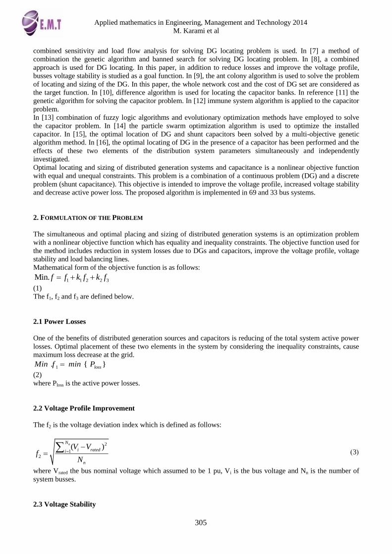
Fig. 8 Network voltage stability index charts for the 33 bus system before and after the installation of a DG and
capacitor banks
Table 4. Comparison of a type-1 DG installation in 33 bus system with other algorithms
Proposed algorithm GA [3] ABC[4] Analytical[1] Optimization Algorithm
61 61 61 61 Optimized location
2590 2380 2400 2490 Optimized value
1 1 1 1 Optimized power factor
48.47 44.83 48.19 47.33 Value of power loss decrease
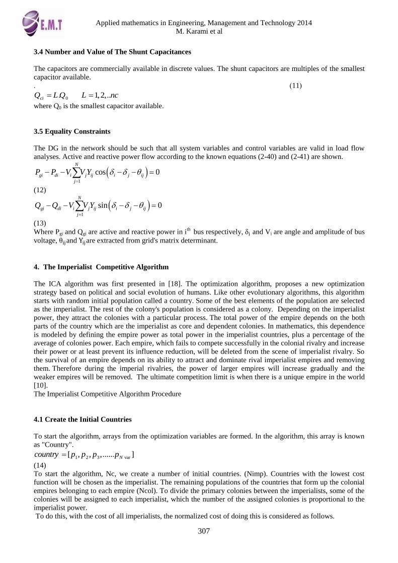
5.2 The 69 Bus System
The line and load data are obtained from [18]. The system voltage is 6/12 kv. Total system active and reactive
loads are MW 8.3 and 69.2 MVar respectively.
Fig. 9 - The 33-bus system schematic
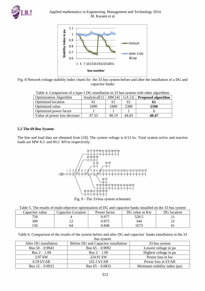
Table 5. The results of multi-objective optimization of DG and capacitor banks installed on the 33 bus system
DG location DG value in Kw Power factor Capacitor Location Capacitor value
11
21
61
528.5
344
1673
0.977
0.875
0.848
4
12
64
750
300
150
Table 6. Comparison of the results of the system before and after DG and capacitor banks installation in the 33
bus system
After DG installation Before DG and Capacitor installation 33 bus system
Bus 50 – 0.9943 Bus 65 – 0.9092 Lowest voltage in pu
Bus 2 – 1.00 Bus 2 – 1.00 Highest voltage in pu
3.97 kW 224.91 kW Power loss in kw
6.59 kVAR 102.1 kVAR Power loss in kVAR
Bus 12 – 0.9923 Bus 65 – 0.6833 Minimum stability index (pu)
0.6
0.7
0.8
0.9
1
1.1
1 4 7 1013161922252831St
abili
ty in
de
x in
pu
bus number
Default
With 3 DG &Cap

Applied mathematics in Engineering, Management and Technology 2014
M. Karami et al
313
Table 7. Summary of the power quality factors improvement
System Active power loss
reduction
Lowest bus voltage Lowest voltage
stability
33 bus 94.1 0.9038 to 0.9944 0.6667 to 0.9776
69 bus 98.2 0.9092 to 0.9944 0.6823 to 0.9923
Table 8. Comparison of a type-1 DG installation in 69 bus system with other algorithms
Proposed
algorithm
GA [3] ABC[4] Analytical[1] Optimization
Algorithm
61 61 61 61 Optimized
location
1872 1839 1900 1810 Optimized value
1 1 1 1 Optimized
power factor
63.2 62.91 62.97 62.86 Value of power
loss decrease
6. Conclusion
DG and shunt capacitors have a large impact on distribution system performance. It can be seen that after the
optimal installation of these two elements, the system reactive power loss decreased of about 94% at 33 bus
systems and has been reduced by approximately 98% at 69 bus system. Figures 4 and 5 and Figures 7 and8 in
33 bus 69 bus system shows that the increase in stability and improve in the voltage profile.
Conclusion
In this paper, the imperial competitive algorithm for the problem of locating and locating the shunt capacitor
banks and distributed generation sources were employed. The problem as modeled as a multi-objective problem
that aims to reduce the real power loss, improving voltage stability and improves the voltage profiles. The
method was implemented on the standard 33 bus and 69 bus systems. The obtained results shows, improved
power quality parameters and the high efficiency of the algorithm in complex optimization problems. The high
speed, high performance and flexibility of the algorithm shows that this algorithm can be employed as an
optimal locating method for DGs in the distribution network.
Fig. 10 - The 69 bus network voltage profile before and after DG and capacitor bank installation
0.9
0.92
0.94
0.96
0.98
1
1.02
1 5 9 13 17 21 25 29 33 37 41 45 49 53 57 61 65 69
Vo
ltag
e in
pu
bus number
Default
3 DG & Cap

Applied mathematics in Engineering, Management and Technology 2014
M. Karami et al
314
Fig. 11 - The 69 bus network stability index before and after DG and capacitor bank installation
REFERENCES
[1] Ng .H. N, Salama .M. M. A, and Chikhani .A. Y, "Classification of capacitor allocation techniques," IEEE Transactions
on power Delivery, vol. 15, no. 1, pp. 387-392, 2000.
[2] Mendes .A, Franca .P.M, Lyra .C, Pissarra .C, and Cavellucci .C, "Capacitor placement in large-sized radial distribution
networks, " IEEE Proceedings-Generation, Transmission and Distribution , vol. 152 ,no. 4,pp. 495-502,2005.
[3] Brown .R. E," Modeling the reliability impact of distributed generation," IEEE Power Engineering Society Summer
Meeting , vol. 1, pp 442-446, 2002.
[4] Algorithm Fahad S. Abu-Mouti, and M. E. El-Hawary, "Optimal Distributed Generation Allocation and Sizing in
Distribution Systems via Artificial Bee Colony " IEEE TRANSACTIONS ON POWER DELIVERY, VOL. 26, NO. 4,
OCTOBER 2011 E.
[5] Quoc Hung .D, Mithulananthan .N and Bansal. R. C, "Analytical Expressions for DG Allocation in Primary
Distribution Networks", IEEE TRANSACTIONS ON ENERGY CONVERSION, VOL. 25, NO. 3, SEPTEMBER 2010
[6] Popovic .D. H, Greatbanks .J. A, Begovic .M, and Pregelj .A, "Placement of distributed generators and reclosers for
distribution network security and reliability," International Journal of Electrical Power & Energy Systems, vol. 27,no. 5-6,
pp. 398-408, 2005.
[7] Gandomkar .M, Vakilian .M, and Ehsan .M, "A Genetic-Based Tabu Search Algorithm for Optimal DG Allocation in
Distribution Networks," Electric Power Components and Systems, vol. 33, pp. 1351-1362, Dec. 2005.
[8] Moradi .M.H, Abedini .M,"A combination of genetic algorithm and particle swarm optimization for optimal DG
location and sizing in distribution systems", Electrical Power and Energy Systems 34 (2012) 66–74
[9] Falaghi .H and Haghifam .M. R," ACO Based algorithm for distributed generation sources allocation and sizing in
distribution systems," IEEE Lausanne Power Tech, pp. 555-560, 2007.
[10] Shukla .T. N, Singh. S. P, Srinivasarao. V, and Naik .K. B, "Optimal sizing of distributed generation placed on
radial distribution systems," Elect. Power Compon. Syst., vol. 38, no. 3, pp. 260–274, 2010
[11] Chiou .J, Chang. C. F, Su. C. T, "Capacitor Placement in Large-Scale Distribution Systems using Variable Scaling
Hybrid Differential Evolution," Electrical Power and Energy Systems ,Vol. 28, No. 10, pp. 739-745, 2006.
[12] Kennedy, J. and Eberhart, R., "Particle swarm optimization," IEEE International Conference on Neural Networks,
1995.
[13] M. Dlfanti, G. P. Granelli, P. Maranninio, "Optimal Capacitor Placement using Deterministic and Genetic
Algorithm," IEEE Trans. On Power Systems, PWRS-15; Vol. 15, No. 3, pp. 1041-1046,2000
[14] T. L. Huang, Y. T. Hsiao, C. H. Chang, J. A.Jiang, “Optimal placement of capacitors in distributionsystems using
an immune multi-objective algorithm,”International Journal of Electrical Power & Energy Systems, vol. 30, no. 3, pp. 184-
192, 2008.
[15] D. Das, "Optimal Placement of Capacitors in Radial Distribution System using a Fuzzy-GA Method,"
International Journal of Electrical Power & Energy Systems, Vol. 30, No. 6, pp. 361-367, 2008.
[16] Abdelsalam A. Eajal, , , and M. E. El-Hawary, , IEEEOptimal Capacitor Placement and Sizing inUnbalanced
Distribution Systems With HarmonicsConsideration Using Particle Swarm OptimizationIEEE TRANSACTIONS ON
POWER DELIVERY, VOL. 25, NO. 3, JULY 2010
[17] Esmaeilian H, Darijany O, Mohammadian M. Optimal placement and sizing of DGs and capacitors
simultaneously in radial distribution networks based on voltage stability security margin. TUBITAK 2013; in press.
0.9
0.92
0.94
0.96
0.98
1
1.02
1 5 9 13 17 21 25 29 33 37 41 45 49 53 57 61 65 69
Vo
ltag
e in
pu
bus number
Default
3 DG & Cap

Applied mathematics in Engineering, Management and Technology 2014
M. Karami et al
315
[18] M.Wang, J. Zhong, A Novel Method forDistributed Generation and Capacitor OptimalPlacement considering
Voltage Profiles, IEEE Power and Energy Society General Meeting, 2011
[19] Charkravorty M, Das D. Voltage stability analysis of radial distribution networks. Int J Electrcal Power Energy
Syst 2001;23(2):129–35.
[20] Atashpaz-Gargari. E, Lucas. C," Imperialist competitive algorithm: an algorithm for optimization inspired by
imperialistic competition". IEEE Congress on Evolutionary Computation, 2007, CEC 2007, 2007,pp. 4661–4667.
[21] Baran ME, Wu FF. Optimal Sizing of capacitor placed on radial distribution systems. IEEE Trans Power Deliv
1989;4(1):735–43.