simultaneous energy harvesting and vibration control via ... · simultaneous energy harvesting and...
TRANSCRIPT

Simultaneous Energy Harvesting and Vibration
Control via Piezoelectric Materials
Ya Wang
Dissertation submitted to the faculty of the Virginia Polytechnic Institute and State
University in partial fulfillment of the requirements for the degree of
Doctor of Philosophy
In
Mechanical Engineering
Daniel J. Inman, Chair
Dwight Viehland
Mary Kasarda
Shashank Priya
Alexander Leonessa
January 27, 2012
Blacksburg, VA
Keywords: Energy Harvesting, Vibration Control, Multi-functionalities, Composite
Structures, Piezoelectric Materials, Gust Alleviation
Copyright © 2012 Ya Wang

Simultaneous Energy Harvesting and Vibration
Control via Piezoelectric Materials
Ya Wang
ABSTRACT
This work examines a novel concept and design of simultaneous energy harvesting and
vibration control on the same host structure. The motivating application is a
multifunctional composite sandwich wing spar for a small Unmanned Aerial Vehicle
(UAV) with the goal of providing self-contained gust alleviation. The basic idea is that
the wing itself is able to harvest energy from the ambient vibrations along with available
sunlight during normal flight. If the wing experiences any strong wind gust, it will sense
the increased vibration levels and provide vibration control to maintain its stability. This
work holds promise for improving performance of small UAVs in wind gusts.
The proposed multifunctional wing spar integrates a flexible solar cell array, flexible
piezoelectric wafers, a thin film battery and an electronic module into a composite
sandwich structure. The basic design factors are discussed for a beam-like
multifunctional wing spar with energy harvesting, strain sensing and self-controlling
functions. The investigated design factors for optimal power generation include the
configuration, location and actuation type of each piezoelectric transducer. The
equivalent electromechanical representations of a multifunctional wing spar is derived
theoretically, simulated numerically and validated experimentally.
Special attention is given to the development of a reduced energy control (REC) law,
aiming to minimize the actuation energy and the dissipated heat. The REC law integrates
a nonlinear switching algorithm with a positive strain feedback controller, and is

iii
represented by a positive feedback operation amplifier (op-amp) and a voltage buffer op-
amp for each mode. Experimental results exhibit that the use of nonlinear REC law
requires 67.3 % less power than a conventional nonlinear controller to have the same
settling time under free vibrations.
Nonlinearity in the electromechanical coupling coefficient of the piezoelectric transducer
is also observed, arising from the piezoelectric hysteresis in the constitutive equations
coupling the strain field and the electric field. If a constant and voltage-independent
electromechanical coupling coefficient is assumed, this nonlinearity results in
considerable discrepancies between experimental measurements and simulation results.
The voltage-dependent coupling coefficient function is identified experimentally, and a
real time adaptive control algorithm is developed to account for the nonlinear coupling
behavior, allowing for more accurate numerical simulations.
Experimental validations build upon recent advances in harvester, sensor and actuator
technology that have resulted in thin, light-weight multilayered composite sandwich wing
spars. These multifunctional wing spars are designed and validated to able to alleviate
wind gust of small UAVs using the harvested energy. Experimental results are presented
for cantilever wing spars with micro-fiber composite transducers controlled by reduced
energy controllers with a focus on two vibration modes. This work demonstrates the use
of reduced energy control laws for solving gust alleviation problems in small UAVs,
provides the experimental verification details, and focuses on applications to autonomous
light-weight aerospace systems.

iv
DEDICATION
To the memory of my grandma Ms. Ren
To my parents, Qiudong Wang and Yuexia Shao,
for their unconditional love, understanding and moral support,
To my brother Wengang Wang and my sister Xi Wang,
for the fond memories of childhood.

v
ACKNOWLEDGEMENTS
First and foremost, I would like to express my heartfelt appreciation and gratitude to my
advisor Professor Daniel J. Inman, the director of the Center for Intelligent Material
Systems and Structures (CIMSS) for providing me with endless encouragement and
guide me through multitude of challenges. I still remember my first meeting with
Professor Inman in his office, when I have no clue where my PhD was heading. I still
remember his encouraging words during the first meeting, when I have no idea whether it
was possible to finish my PhD given my circumstances. Things were not looking so
bright at that time and Prof. Inman gave me hope and made me realized that with right
direction, hard work and persistence, pursuing my dream was not an impossible task.
Over these years, Professor Inman has shown be the excellent example he has provided
as a successful scientist, researcher, teacher and advisor, both consciously and
unconsciously. The enthusiasm, curiosity, sense of humor, joy and effort he has for his
research was very impressive, motivational, infusive and contagious. He was always full
of ideas and open for new ideas. He never doubted my capabilities, always preserved his
confidence in me and guided me through tough times. Even though he is one of the
busiest men on earth, he was always available, always listened and always cared.
Professor Inman was also incredibly patient and never ever got angry or upset over my
missteps. Instead, he spent countless hours proofreading my research papers, discussing
research problems, seeking new research topics. These are all one student can expect and
ask from an advisor. There is no way to pay back for his admirable, inspirational and
immeasurable dedication, but at least I can promise that I will keep this spirit and mentor
to my own students in the future.
I would also like to extend my great acknowledgement to Dr. Kasarda, Prof. Viehland,
Prof. Priya and Dr. Leonessa for serving on my Ph.D committee. It has been my great
pleasure to have the support of such knowledgeable professors. Of course, my learning
experience would not have been this joyful without their wise advices and unquestionable
expertise.

vi
I would like to express my immense appreciation to Mechanical Engineering Department
at Virginia Tech, particularly the CIMSS. Sincere thanks to Ms. Margaret E. Howell
(Beth), the program manager of CIMSS, for creating such a friendly office and research
environment, for being supportive for any project and administrative related problems. I
feel so grateful to have so many amazing colleagues in CIMSS for sharing their ideas and
expertise in theoretical, numerical and excremental subjects. They are willing to provide
help in any way possible and they have contributed immensely to my personal and
professional time at Virginia Tech. There are too many to list here completely. First,
thank Dr. Onur Bilgen for his invaluable help and sincere assistance with experimental
setup. Thank Justin Farmer for helping me around the lab with introducing our lab
equipment. Thank Dr. Andy Sarles for his help with many dSPACE related problems.
Thank Dr. Steve Anton for introducing his self-charging structure and providing me a
solid research platform. Thank Dr. Ha Dong, Dr. Na Kong and John Tuner for their help
with printed circuit board design. Thank Dr. Amin, Karami for the discussion in all
academic issues. I would like to thank Mona Afshari and Jacob Dodson for being
amazing office mates. I also enjoyed sharing the same lab with my colleagues Jared
Hobeck and Alexander Pankonien during my visit in Aerospace Engineering at The
University of Michigan.
I am so in debts to my late grandma and my parents for their sacrifice, unreserved support
and belief in me. They are amazing parents who always putting their children first
without question. I also owe thanks to my amazing brother and sister for being a strong
support for the whole family when I am away from home. I am deeply blessed to have
them as my family. I also feel extremely lucky to have some of the most interesting
Chinese students at Virginia Tech and The University of Michigan. I appreciate for their
sincere friendship: Dr. Weihua Su, Jie Wang, Qingzhao Wang and many others.
I gratefully acknowledge the funding source that made my Ph.D. work possible. I was
funded by the U.S. Air Force Office of Scientific Research under the grant F9550-09-1-
0625 ‘Simultaneous Vibration Suppression and Energy Harvesting’ monitored by Dr B.L.
Lee.

vii
TABLE OF CONTENTS
ABSTRACT ........................................................................................................................ ii
DEDICATION ................................................................................................................... iv
ACKNOWLEDGEMENTS ................................................................................................ v
TABLE OF CONTENTS .................................................................................................. vii
LIST OF FIGURES ............................................................................................................ x
LIST OF TABLES ............................................................................................................ xv
CHAPTER 1 INTRODUCTION ........................................................................................ 1
Objective of the Dissertation .......................................................................................... 1
Layout of the Dissertation ............................................................................................... 3
CHAPTER 2 LITERATURE REVIEW ............................................................................. 7
Nomenclature .................................................................................................................. 8
Introduction ..................................................................................................................... 9
Review of Existing Modeling of Vibration-based Cantilever Piezoelectric Energy
Harvesters ..................................................................................................................... 12
Equivalent Electromechanical Circuit for Vibration-based Cantilever Piezoelectric
Harvesters ................................................................................................................. 13
Dynamic Modeling for Vibration-based Cantilever Piezoelectric Harvester ........... 13
Power Conditioning Circuitry and Power Optimization: ......................................... 16
Damping Effect due to Energy Dissipation Resulting from Energy Harvesting ...... 19
The State of Art of Vibration Control Laws via Piezoceramics ................................... 20
Purely Passive Shunt Damping ................................................................................. 21
Semi-passive Shunt Damping and the Switching Technology ................................. 22
Semi-active Control .................................................................................................. 29
Active Control ........................................................................................................... 32
Chapter Summary ......................................................................................................... 33
CHAPTER 3 REDUCED ENERGY CONTROL LAW .................................................. 35
Nomenclature ................................................................................................................ 36
Introduction ................................................................................................................... 37
Conventional Active Control Systems .......................................................................... 39
viii
PPF Control ............................................................................................................... 40
PID Control ............................................................................................................... 42
Nonlinear Control ..................................................................................................... 43
LQR Control ............................................................................................................. 44
Hybrid Bang-bang Control Systems ............................................................................. 45
Experimental Results ................................................................................................ 47
Numerical Simulations.................................................................................................. 53
Simulations with Voltage-independent Electromechanical Coupling ...................... 53
State Variable Simulation with Voltage-dependent Electromechanical Coupling ... 55
Chapter Summary ......................................................................................................... 60
CHAPTER 4 SIMULTANESOU ENERGY HARVESTING AND GUST
ALLEVIATION FOR A MULTIFUNCTIONAL WING SPAR ..................................... 61
Nomenclature ................................................................................................................ 62
Introduction ................................................................................................................... 63
Electromechanical Cantilever Beam Model of A Multifunctional Wing Spar using
Assumed Modes ............................................................................................................ 66
Electromechanical Energy Components Using Distributed-Parameter Method ...... 67
Solving Electromechanical Euler-Lagrange Equations for Piezoelectric Harvesters 69
Design Considerations for a Multifunctional Composite Wing Spar ....................... 73
Simultaneous Energy Harvesting and Gust Alleviation using REC ............................. 78
Equivalent Circuit Representation of a Piezoelectric Generator .............................. 78
Generation of Normal Wing Vibration and Wind Gust Signals ............................... 79
Gust Alleviation Using REC Control Laws: ............................................................. 81
Power Flow for Simultaneous Energy Harvesting and Gust Alleviation ................. 83
Chapter Summary ......................................................................................................... 87
CHAPTER 5 EXPERIMENTAL VALIDATION OF AN AUTONOMOUS GUST
ALLEVIATION SYSTEM ............................................................................................... 88
Nomenclature ................................................................................................................ 88
Introduction ................................................................................................................... 89
Experimental Validation of Reduced Energy Control on a Piezoelectric Layer Bonded
Aluminum Wing Spar ................................................................................................... 90

ix
Experimental Setup for Validation of Reduced Energy Control Law ...................... 90
Experimental Results ................................................................................................ 92
Experimental Characterization and Validation of an Autonomous Gust Alleviation
System on a Honeycomb Core Fiberglass Composite Sandwich Wing Spar ............... 98
Experimental Setup for Harvesting Ability Characterizations of Monolithic QP10n
and Micro Fiber Composite MFC 85281P1.............................................................. 99
Experimental Characterizations of Harvesting Abilities for Monolithic QP10n
Transducer............................................................................................................... 103
Experimental Characterizations of Harvesting Abilities for Micro Fiber Composite
MFC 8528 P1 .......................................................................................................... 106
Experimental Validations of the Autonomous Gust Alleviation System on the
Fiberglass Composite Multifunctional Wing Spar ................................................. 109
Chapter Summary ....................................................................................................... 112
CHAPTER 6 DISSERTATION SUMMARY ................................................................ 113
APPENDICES ................................................................................................................ 115
Appendix A Piezoelectric Constitutive Equations ...................................................... 115
Standard 3D Form of Constitutive Equations ......................................................... 115
Reduced Equations for 3-1 Actuation Modes ..................................................... 115
Reduced Equations for 3-3 Actuation Modes ..................................................... 116
Appendix B Euler-Lagrange Equations using Extended Hamilton’s Principle .......... 118
Appendix C Cross-section Transformation ................................................................ 119
Appendix D Energy Formulations of Electromechanical Cantilever Beam using
Distributed Parameter Method .................................................................................... 120
Appendix E Dryden Power Spectral Density Spectrum ............................................. 123
BIBLIOGRAPHY ........................................................................................................... 124

x
LIST OF FIGURES
Figure 1.1 Energy flow for simultaneous energy harvesting and vibration control. .......... 1
Figure 2.1 (a) A prototype of multifunctional structure with simultaneous energy
harvesting and vibration control abilities (b) Its schematic representation (c) Its feedback
control block. .................................................................................................................... 11
Figure 2.2 Equivalent circuit representation of the vibration-based piezoelectric harvester.
........................................................................................................................................... 13
Figure 2.3 A schematic diagram of (a) lumped-parameter (b) distributed-parameter
model................................................................................................................................. 15
Figure 2.4 (a) Standard energy harvesting (SEH) (b) Synchronous charge extraction
(SCE) (c) Synchronized switching harvesting on inductor (SSHI) .................................. 16
Figure 2.5 Purely passive shunted system using PZT-based transducers. ........................ 22
Figure 2.6 Schematic diagram of (a) state switch (b) SSDS (c) SSDI and (d) SSDV. ..... 24
Figure 2.7 (a) SSDS in Richard et al. (1999b) (b) SSDI in Richard et al. (2000). ........... 26
Figure 3.1 Block diagrams of the (a) conventional and (b) hybrid control system. ......... 46
Figure 3.2 (a) Picture and (b) schematic diagram of experimental setup. ....................... 47
Figure 3.3 Tip displacement measurements of the (a) Open-loop (b) PPF, Bang-bang-PPF
(c) PID, Bang-bang-PID (d) Nonlinear, Bang-bang-nonlinear (e) LQR, Bang-bang-LQR
control systems with identical initial conditions. .............................................................. 49
Figure 3.4 Experimental actuation voltage histories for the (a) PPF, Bang-bang-PPF (b)
PID, Bang-bang-PID (c) Nonlinear, Bang-bang-nonlinear (d) LQR, Bang-bang-LQR
control systems with identical initial conditions. .............................................................. 50
Figure 3.5 Experimental actuation current histories for the (a) PPF, Bang-bang-PPF (b)
PID, Bang-bang-PID (c) Nonlinear, Bang-bang-nonlinear (d) LQR and Bang-bang-LQR
control systems with identical initial conditions. .............................................................. 50
Figure 3.6 Experimental instantaneous power consumption for the (a) PPF, Bang-bang-
PPF (b) PID, Bang-bang-PID (c) Nonlinear, Bang-bang-nonlinear (d) LQR and Bang-
bang-LQR control systems with identical initial conditions............................................. 52

xi
Figure 3.7 Numerical and experimental comparisons of tip displacement, control voltage
and control current of (a) PPF and (b) Bang-bang-PPF control systems. ......................... 54
Figure 3.8 Numerical and experimental comparisons of tip displacement and control
voltage of (a) PID (b) Bang-bang-PID (c) Nonlinear (d) Bang-bang-nonlinear (e) LQR
and (f) Bang-bang-LQR control systems. ......................................................................... 55
Figure 3.9 Variation of the electromechanical coupling coefficient (feedback constant)
with actuation voltage. ...................................................................................................... 57
Figure 3.10 Block diagram of the state variable or adaptive control system. ................... 57
Figure 3.11 State variable numerical and experimental comparisons of tip displacement,
control voltage and control current of the (a) PPF (b) Bang-bang-PPF control systems. 58
Figure 3.12 State variable numerical and experimental comparisons of tip displacement
response and control voltage of the (a) PID (b) Bang-bang-PID (c) nonlinear (d) Bang-
bang-nonlinear (e) LQR and (f)Bang-bang-LQR control systems. .................................. 59
Figure 4.1 Multifunctional wing spar design showing various functionalities including
self-sensing, self-harvesting, self-storage and self-control. .............................................. 65
Figure 4.2 A composite spar for a small remote control aircraft( Anton et al. (2010)). ... 66
Figure 4.3 Relative tip frequency response function using both analytical and FEM
modeling. .......................................................................................................................... 73
Figure 4.4 Output power versus load resistance at mode 1 of 29Hz and mode 2 of 107 Hz.
........................................................................................................................................... 75
Figure 4.5 Output power of MFC 8528 P1versus distance from clamped end at mode 1 of
29 Hz and mode 2 of 107Hz. ............................................................................................ 76
Figure 4.6 Output power of QP10n versus distance from clamped end at mode 1 of 29 Hz
and mode 2 of 107Hz. ....................................................................................................... 77
Figure 4.7 The equivalent circuit for 1st mode piezoelectric generator with resistive
impedance. ........................................................................................................................ 78
Figure 4.8 The output voltage to base acceleration FRF for an 112Kohm Load
Resistance. ........................................................................................................................ 79
Figure 4.9 The harvested power spectrum for a 0.1 M ohm load resistance. ................... 79

xii
Figure 4.10 Block diagram of wind gust signal generation for open-loop and close-loop
tip displacement responses. ............................................................................................... 80
Figure 4.11Ambient wing vibration and wind gust acting on multifunctional wing spar
base, U0=15m/s, Lv =350m. .............................................................................................. 81
Figure 4.12 Schematic representations of gust alleviation using harvested energy. ........ 82
Figure 4.13The disturbed tip displacement spectrum of multifunctional wing spar before
and after REC control. ...................................................................................................... 83
Figure 4.14Winds disturbed multifunctional wing spar tip response in time domain before
and after REC control. ...................................................................................................... 83
Figure 4.15 Block Diagram of the 1st Mode PSF Control. ............................................... 84
Figure 4.16 Active and reactive power spectrum of 1st Mode and 2
nd Mode PSF and
buffer Op-amps. ................................................................................................................ 85
Figure 4.17Active and reactive power associated with the summing Op-amp and the
MFC 8528 P1actuator. ...................................................................................................... 86
Figure 5.1 (a) A photographic (b) A schematic representation of front view and back
view of the aluminum baseline multifunctional wing spar. .............................................. 91
Figure 5.2 Gust alleviation experimental setup using REC Laws. ................................... 92
Figure 5.3 Control performance of the PSF controllers for different control gains
(damping ratio of mode 1: ζ1= 0.15 and mode 2: ζ2 = 0.35). ........................................... 93
Figure 5.4 Vibration control performance using the PSF and REC Laws. ....................... 94
Figure 5.5 Control performance using PSF and REC laws (time history of relative tip
displacement response). .................................................................................................... 95
Figure 5.6 Actuation voltage measurements required by the PSF and REC laws. ........... 95
Figure 5.7 Actuation current measurements required by the PSF and REC laws. ........... 96
Figure 5.8 Instantaneous power required by PSF and REC laws. ................................... 96
Figure 5.9 Active and reactive power required by PSF and REC laws. ........................... 97
Figure 5.10 (a) A photographic representation (b) a schematic representation of the
autonomous gust alleviation system building on a honeycomb core fiberglass
multifunctional wing spar. ................................................................................................ 99
Figure 5.11 A prototype of (a) the MFC 8528P1 (b) the QP10n. ..................................... 99

xiii
Figure 5.12 A photographic representation of (a) the DP460 glue gun (b) the vacuum
process (c) the pressure meter panel. .............................................................................. 100
Figure 5.13 (a) Energy harvesting experimental setup for QP10n piezoelectric harvester
(b) dSPACE data acquisition system. ............................................................................. 102
Figure 5.14 Experimental and numerical simulation comparison of the first two mode
voltage-per-acceleration with a set of effective load resistance excited by clear sky
atmospheric turbulence for the QP10n piezoelectric harvester. ..................................... 103
Figure 5.15 Experimental and numerical simulation comparison of the first two mode
current-per-acceleration with a set of effective load resistance excited by clear sky
atmospheric turbulence for the QP10n piezoelectric harvester. ..................................... 104
Figure 5.16 Experimental and numerical simulation comparison of the first two mode
power-per-acceleration with a set of effective load resistance excited by clear sky
atmospheric turbulence for the QP10n piezoelectric harvester. ..................................... 104
Figure 5.17 Experimental and numerical simulation comparison of the voltage-to-base-
acceleration FRF at optimum load resistance excited by clear sky atmospheric turbulence
for the QP10n piezoelectric harvester. ............................................................................ 105
Figure 5.18 The measured voltage-to-base-acceleration FRF at a set of load resistance
excited by clear sky atmospheric turbulence for the QP10n piezoelectric harvester. .... 106
Figure 5.19 Experimental and numerical simulation comparison of the first two mode
voltage-per-acceleration with a set of effective load resistance excited by clear sky
atmospheric turbulence for the MFC 8528P1 piezoelectric harvester. ........................... 106
Figure 5.20 Experimental and numerical simulation comparison of the first two mode
current-per-acceleration with a set of effective load resistance excited by clear sky
atmospheric turbulence for the MFC 8528P1 piezoelectric harvester. ........................... 107
Figure 5.21 Experimental and numerical simulation comparison of the first two mode
power-per-acceleration with a set of effective load resistance excited by clear sky
atmospheric turbulence for the MFC 8528P1 piezoelectric harvester. ........................... 107
Figure 5.22 Experimental and numerical simulation comparison of the voltage-to-base-
acceleration FRF at optimum load resistance excited by clear sky atmospheric turbulence
for the QP10n piezoelectric harvester. ............................................................................ 108
Figure 5.23 A finished PCB prototype of Multimode REC Laws. ................................. 109

xiv
Figure 5.24 Experimental setup for the autonomous gust alleviation system. ............... 111
Figure 5.25 A comparison of relative tip displacement frequency spectrum response
predicted with numerical simulation for the first two modes, showing both open loop and
closed loop cases. ............................................................................................................ 112
Figure A.1Piezoelectric transducers with (a) 3-1 actuation mode (b) 3-3 actuation
mode. ............................................................................................................................... 116
Figure C.1 Cross section transformation of (a) original beam (b) transformed
homogeneous beam. ........................................................................................................ 119
Figure D.1 Representation of a Euler-Bernoulli cantilever beam with multiple PZT
layers. .............................................................................................................................. 120

xv
LIST OF TABLES
Table 2.1 Numerical and Experimental Shunt Parameters in Corr and Clark (2001a). .... 25
Table 2.2 Experimental Parameters and Damping Results for SSDI(Richard et al. (2000)).
........................................................................................................................................... 28
Table 2. 3 Summary of the Main Characteristics of SSDS and SSDI Systems in Free and
Forced Response in Ducarne et al. (2010). ....................................................................... 28
Table 3.1Properties of the Beam and the Piezoelectric Transducer (MFC). .................... 48
Table 3.2 Experimental comparisons of the PPF, Bang-bang-PPF, PID, Bang-bang-PID,
Nonlinear, Bang-bang-nonlinear, LQR and Bang-bang-LQR control systems. ............... 52
Table 4.1Selected properties of compared piezoelectric transducers. .............................. 74
Table 4.2 Selected properties of other components for multifunction wing spar design. 77
Table 4.3Power Associated With Each Electric Component............................................ 86
Table 5.1 Geometry and Material Properties for the Aluminum Baseline Multifunctional
Wing Spar. ........................................................................................................................ 91
Table 5.2 Control Performance versus PSF Control Gain. ............................................... 93
Table 5.3 Power and Energy Elements Associated with PSF and REC Laws. ................ 97
Table 5.4 Geometry and Material Properties for Two Unimorph Piezoelectric Harvesters.
......................................................................................................................................... 100
Table 5.5 Nominal Resistors and their Effective Values. ............................................... 101
Table 5.6 Experimentally Property Identification of Two Piezoelectric Harvesters. ..... 109
Table 5.7 Component Parameters of PCB Layout for Multimode Vibration Control. ... 110
Table 5.8 Experimentally Identified Properties for the PCB Device. ............................. 110

1
CHAPTER 1 INTRODUCTION
OBJECTIVE OF THE DISSERTATION
The goal of this dissertation is to demonstrate the feasibility, realization and
implementation of the concept and design of using harvested energy to directly control
the vibration response of flexible aerospace systems via piezoelectric materials.
Advanced techniques in aerospace systems usually require structures with low weight,
high strength, high damping and adaptive charging capabilities. Structural components of
satellites or unmanned aerial vehicles (UAVs) are often flexible and hence are easily
disturbed into vibration from a variety of sources. Repositioning maneuvers can cause
impulsive loads to the structure and hence excite broadband vibration, and rotating
components can cause persistent vibrations. Small, lightweight flexible UAVs provide
both harvesting opportunities and vibration suppression requirements. Hence the
motivation of this dissertation is to investigate the possibility that the aforementioned
ambient energy might be harvested and recycled to provide energy to mitigate the
vibrations through various control laws. Smart structure technology which incorporates
sensors, actuators, and real time control laws within composite sandwich substrates can
be implemented in such systems to achieve the required characteristics. The intention of
this dissertation is to develop an analytical basis for characterizing the feasibility of using
harvested ambient energy to suppress vibrations in aerospace structures. This intention
can also be illustrated by the basic scenario of energy flow shown in Figure 1.1. Ambient
sources from vibration, solar or thermal can be captured via piezoelectric transducers, and
then used for other purposes, such as vibration control or structural health monitoring.
Figure 1.1 Energy flow for simultaneous energy harvesting and vibration control.
ambient energy:
vibration, solar or thermal
Mechanical
Dissipation
Electrical
Dissipation
Vibration
Control
Thermal
Energy
Harvested
Energy

2
This research goal will be met by addressing the following objectives: 1) to develop a
model for piezoelectric and fiber composite materials integrated into flexible components
for a multifunctional cantilever beam; 2) to derive a predictive model for energy
conversion from embedded piezoelectric and fiber composite materials including the
associated electronics; 3) to explore a feedback control law based on minimum energy
constraints provided by the harvested ambient energy; 4) to experimentally validate the
theory produced in item 3; 5) to integrate the actuating, harvesting and sensing materials
into a composite sandwich structural element to form a multifunctional structure with
structural sensing , harvesting and control functionality; 6) to establish ambient vibration
levels for a typical small UAV to represent both normal fight condition and wind gust
disturbance; 7) to design frequency domain gust alleviation systems supplied by local
power sources harvested from ambient energy.
The following tasks outline approaches to achieve these proposed research objectives in
simultaneous energy harvesting and vibration control: 1) to develop and derive the
electromechanical governing equations for vibration and control of a multifunctional
composite structure consisting of embedded piezoelectric and fiber composite materials
in the general aerospace structures; 2) to explore the feedback control laws for vibration
suppression requiring the least amount of energy; 3) to design a multifunctional structure
with integrated piezoelectric and fiber composite materials, considering bending strength,
bending stiffness, and other optimal design factors; 4) to determine the feasibility of
using harvested energy to suppress vibration in the designed multifunctional structure; 5)
to examine the vibration suppression performance provided by a piezoelectric-based
harvesting device and the key parameters effecting maximum suppression; 6) to design a
proof of concept experiment to validate the results found in the first five tasks; 7) to apply
this concept and design for a composite sandwich wing spar with the goal of providing
self-contained gust alleviation; 8) to design a proof of concept experiment to validate the
design of task 7.
In summary, these research objectives address the question of whether or not harvested
ambient energy can be used to provide enough control effort to deliver a reasonable level
3
of vibration suppression and to quantify the degree to which such control can be
accomplished. The proposed effort focuses on the generic aerospace related systems. The
ambient energy sources considered are mechanical vibrations to be harvested by the
piezoelectric and fiber composite materials. Considering various control methodologies
explored for suppressing vibration, a reduced energy is developed to examine vibration
control performances with strong limits on the control input energy. A multifunctional
approach is applied to integrate the piezoelectric, fiber composite transducer materials
along with the control and harvesting electronics into the structure elements. One of the
promising applications of simultaneous energy harvesting and vibration control in aircraft
is in providing local power source to autonomous gust alleviation systems of a self-
contained small UAV. The research demonstrated in this dissertation integrates
piezoelectric energy harvester, smart materials, multifunctional structures and composite
sandwich structures into a UAV platform to perform simultaneously gust alleviation and
energy harvesting.
The research issues to be addressed are: 1) the characterization of appropriate ambient
energy; 2) the electromechanical modeling of vibration control and collocated
piezoelectric harvesting and strain sensing; 3) the development of vibration control laws
with limited energy consumption; 4) the analysis of bending strength and beam stiffness
analysis for the composite sandwich substrates; 5) the integration of piezoelectric, fiber
composite harvesting materials into a load bearing composite sandwich structure
members to enable multi-functionality; 6) the experimental validation of the scenario of
using harvesting energy to perform control; 7) the incorporation of energy harvesting
devices and gust load alleviation systems into small UAVs, providing local power source
for low-power sensors and controllers in aircraft.
LAYOUT OF THE DISSERTATION
The problem statement of this dissertation is given in Chapter 1. Motivation behind the
proposed concept of simultaneous energy harvesting and vibration control is
demonstrated. The research objective, main tasks and scientific issues are also addressed.

4
A literature review is presented in Chapter 2, starting with mathematical and dynamical
modeling of vibration-based cantilevered energy harvesters ranging from lumped to
distributed parameter base excitation problem. A review of vibration control laws is
presented for schemes using harvested energy as the main source of energy to suppress
vibrations via piezoelectric materials. These control methods are reviewed along the lines
of purely passive, semi-passive, semi-active, and active control. The classification is built
on whether external power is supplied into piezoelectric transducers. Special attention is
paid to recent advances investigating semi-passive and semi-active control strategies
derived from synchronized switching damping (SSD). However, whether or not the
harvested energy is large enough to satisfy a vibration suppression requirement has
become an important topic of research but has not yet specifically been addressed in
previous studies. Hence this chapter also reviews the possible control methods aiming for
less control energy consumption and addresses the potential application for simultaneous
vibration control and energy harvesting.
Chapter 3 details the examination of four conventional vibration suppression control laws
and four hybrid modifications of these laws using a switching method, named Reduced
Energy Control (REC). A hybrid version of each controller is obtained by implementing a
bang-bang control law (on-off control). The bang-bang control algorithm switches the
control voltage between an external voltage supply and the feedback signal provided by
aforementioned four conventional controllers. The purpose of employing the bang-bang
control law is to reduce the power requirement for vibration suppression by providing an
active controller with limited voltage input. The motivation to consider REC is the idea
that in some applications very little energy is available for control, yet passive, semi-
passive or semi-active methods cannot meet performance demands. In particular the
eventual goal is to reduce transient vibrations of smart structures using energy obtained
from harvesting and/or low power storage devices (batteries or super capacitors) as is
often desirable in aerospace systems. Free vibrations of a thin cantilevered beam with a
piezoceramic transducer are controlled by these eight controllers with a focus on the
fundamental transverse vibration mode. Experimental results exhibit that the system with
hybrid bang-bang-nonlinear controller requires 67.3 % less power than its conventional

5
version. Experiments also reveal the presence of substantial piezoelectric nonlinearities in
the transducer. The voltage-dependent behavior of the electromechanical coupling
coefficient is identified empirically and represented by a curve-fit expression. A real-time
state variable control algorithm is developed to account for the voltage-dependent
behavior of the coupling coefficient, enabling good agreement between the simulation
and experimental results.
Chapter 4 presents the design of a multifunctional composite sandwich wing spar in order
to examine the gust alleviation problem of a small UAV. The basic idea is that the wing
itself is able to harvest energy from the ambient vibrations during normal flight along
with available sunlight. If the wing experiences any strong wind gust, it will sense the
increased vibration levels and provide vibration control to maintain its stability. The
multifunctional wing spar integrates a flexible solar cell array, piezoelectric wafers, a thin
film battery and an electronic module into a composite sandwich structure. The basic
design factors are discussed for a beam-like multifunctional wing spar with load-bearing
energy harvesting, strain sensing and self-controlling functions. In particular, the
configurations, locations and actuation types of piezoelectric transducers are discussed
for optimal power generation. The equivalent electromechanical representations of a
multifunctional wing spar are derived theoretically and simulated numerically. A reduced
energy control law is represented by a positive feedback operation amplifier (op-amp)
and a voltage buffer op-amp for each mode. This examines the concept of simultaneous
energy harvesting and vibration, and holds promise for improving UAV performance in
wind gusts.
Chapter 5 is dedicated to experimental characterization and validation of an autonomous
gust alleviation system building upon recent advances in harvester, sensor and actuator
technology that have resulted in thin, ultra-light weight multilayered composite wing
spars. These beam like multifunctional spars are designed to be capable of alleviating
wind gust of small UAVs using the harvested energy. Experimental results are presented
for cantilever wing spars with micro-fiber composite transducers controlled by reduced
energy controllers with a focus on two vibration modes. A reduction of 11dB and 7dB is

6
obtained for the first and the second mode using the harvested ambient energy. This work
demonstrates the use of reduced energy control laws for solving gust alleviation problems
in small UAVs, provides the experimental verification details, and focuses on
applications to autonomous light-weight aerospace systems.
Chapter 6 summarizes the results of this work, addresses the major contributions to the
research community and presents recommendations for future work.

7
CHAPTER 2 LITERATURE REVIEW
This chapter presents a summary of passive, semi-passive, semi-active and active control
methods for schemes using harvested energy as the main source of energy to suppress
vibrations via piezoelectric materials. This concept grew out of the fact that energy
dissipation effects resulting from energy harvesting can cause structural damping.
First, the existing equivalent electromechanical modeling methods are reviewed for
vibration-based cantilevered energy harvesters using piezoelectric transducers. Following
the literature on mathematical and dynamical modeling of these devices ranging from
lumped to distributed parameter base excitation problem, the commonly used electrical
power conditioning circuits and their optimization are presented and discussed.
The energy dissipation from harvesting induces structural damping and this leads to the
concept of purely passive shunt damping. Classification of previous results is built on
whether external power is supplied into piezoelectric transducers. This chapter reviews
the literature on vibration control laws along the lines of purely passive, semi-passive,
semi-active, and active control. The focus is placed on recent articles investigating semi-
passive and semi-active control strategies derived from synchronized switching damping
(SSD).
However, whether or not the harvested energy is large enough to satisfy a vibration
suppression requirement has become an important topic of research but has not yet
specifically been addressed in previous studies. Hence this chapter also reviews the
possible control methods aiming for less control energy consumption and addresses the
potential application for simultaneous vibration control and energy harvesting.

8
NOMENCLATURE
coupling coefficient of PZT-based transducers
feedback control gain
base excitation amplitude
equivalent damping of the beam structure for lumped-parameter moeq
b
A
c
deling
equivalent capacitance, the reciprocal of structural stiffness
inherent capacitance of the PZT-based transducers
damping matrix
base excitation force
s
p
s
C
C
f
f
C
equivalent structure force on PZT-based transducer due to vibration
base excitation forcein terms of a series of finite components
electrical current
equivaleneq
i
k
f
t stiffness of the beam structure for lumped parameter modeling
system coupling coefficient
stiffness matrix
equivalent inductance, the mass or inertia of the PZT-based
sys
s
k
L
K
generator
inductance of the inductive shunt circuit
equivalent mass of the beam structure for lumped parameter modeling
mass of the PZT-based generator
mass
eq
p
L
m
m
M matrix
turn ratio representing the piezoelectric coupling coefficient
equivalent resistance representing the structural damping
electrical voltage
absolutabs
n n
Rs
V
w
e displacement
base displacement
relative displacement
structural displacement at the position of interest
base excitation displacement at the position o
b
rel
w
w
x
y
f interest
external load impedance
structural damping ratio
device coupling coefficient vector
modal coordinates for mode
modal coordinate vec
L
th
r
Z
r
θ
η tor

9
modal loss factor
admissible trial function
base excitation frequency
shut time period for synchronized switching damping on inductance
l
sh
b
t
r
uT
INTRODUCTION
The large-scale and lightweight design trends in aerospace systems give rise to extremely
flexible structures with low-frequency vibration modes. Due to their mechanical
simplicity, light weight, small volume, and ability to be easily integrated into applications
with flexible structures, electromagnetic, electrostatic, and piezoelectric transducers have
been extensively utilized for both energy harvesting and vibration control purposes.
Among these three typical transducer mechanisms, piezoelectric harvesters are prominent
choice for mechanical to electric energy conversion, since the energy density is much
higher compared to other transduction materials for a given profile, see Roundy and
Wright (2004). Their popular utilization is attributed to their excellent sensing as well as
actuation abilities with relatively high electro-mechanical coupling coefficients.
Additionally, piezoelectric materials are easily integrated into applications with flexible
structures. The piezoelectric materials (PZT1) exhibit the piezoelectric effect, which is a
reversible effect that can be divided into two phenomena as the direct and the converse
piezoelectric effects. When a piezoelectric material is mechanically strained, it produces
an electric potential, which can be used for sensing and harvesting (direct piezoelectric
effect). Conversely, when an electric field is applied, it produces a mechanical strain
allowing actuation and shape control (converse piezoelectric effect).
Many ambient energy sources have been investigated for harvesting purposes, falling into
four typical types: solar energy, thermal gradients, acoustic and mechanical vibration.
Mechanical vibration-based energy harvesting is the most popular and practical one. Up
1 Although PZT commonly refers to monolithic piezoceramic material lead-zirconate-titanate, we refer to PZT for
brevity but any piezoelectric material is implied.

10
to now, the review of vibration-based energy harvesting in the past years have been
presented by the following researchers: Sodano, Inman and Park (2004a) reviewed topics
in PZT-based energy harvesting from ambient mechanical vibration. They evaluated the
harvesting efficiency, and discussed the power storage and circuitry. Beeby, Tudor and
White (2006) reviewed various harvesting sources subjected to mechanical vibration such
as household goods and structures, for the objective of removing the external battery
power supply for wireless sensor networks and self-powered micro-systems. The review
paper by Pereyma (2007) provides a performance comparison of different energy sources,
but mainly focuses on vibration energy harvesting devices. Anton and Sodano (2007)
reviewed efficient PZT-based harvesting design based on physical and geometrical
configurations and efficient circuitry through adaptive energy removal techniques, in the
years following the article by Sodano et al. (2004a). For the purpose of on-site real time
energy generation aiming to transfer ambient mechanical energy at the sensor location
into electrical energy, Priya (2007) provided a comprehensive review of PZT-based
energy converters using low profile transducers. He also investigated the energy
harvesting efficiency in literature and discussed the selection of PZT-based transducers
for both on and off resonance applications. Later, Chalasani and Conrad (2008) reviewed
and discussed the power density of various energy harvesting sources, not only from
mechanical vibration, but also photovoltaic cells and thermoelectric generators. Another
review paper given by Cook-Chennault, Thambi and Sastry (2008), addressed the recent
advances of PZT-based energy harvesting technology based on non-regenerative and
regenerative power supplies.
However, not much attention has been given to the important problem of simultaneously
harvesting energy and using that energy to perform control. Hence this chapter reviews
the control methods that consider vibration-based piezoelectric harvester as the main
source of power supply and aims for less control energy consumption. An application of
this concept is a multifunctional wing spar (Figure 2.1) for an Unmanned Aerial Vehicle
(UAV), which is designed to alleviate wind gust using the harvested energy from normal
vibration, proposed in Wang and Inman (2011c). The baseline/ host structure has to carry
out the multiple functions of energy harvesting, strain sensing and vibration control in

11
order to be considered as multifunctional. The multifunctional wing spar considered here
also includes a Printable Circuit Board (PCB) integrating the required electric circuitry,
as illustrated in Figure 2.1 (a). A schematic of the multifunctional wing spar is given in
Figure 2.1(b). Figure 2.1(c) is a representation of the feedback control loop contained
within the spar.
The organization of this chapter is presented in three major sections: section 1 presents
the literature on electromechanical modeling for vibration-based cantilever piezoelectric
energy harvesters. After introducing the equivalent electromechanical modeling, the
review covers modeling methods ranging from lumped parameter to distributed
parameter methods and power conditioning circuitries as well their optimization. Section
2 introduces the damping effect due to energy dissipated in the host structure resulting
from energy harvesting. Section 3 reviews existing vibration control laws via
piezoceramics, ranging from purely passive shunt damping, semi-passive shunt damping
to semi-active and active control methods.
(a) (b)
(c)
Figure 2.1 (a) A prototype of multifunctional structure with simultaneous energy
harvesting and vibration control abilities (b) Its schematic representation (c) Its feedback
control block.
AccelerometerQP10N Shaker MFC 8528P1
PCB
x
z
A. QP16N (Harvester, Sensor)D. Printable Circuit Board (PCB)
B. Honeycomb Core Fiberglass
C. MFC(Actuator)
L1=25 mm L2=84.6 mm
L3=110 mm
L4=552 mm
E. Epoxy DP 460, Kapton
L4=592 mm
PZT LayerSubstrate
PCB
Fixture
Wire
Plantu(t) x(t)
Controller
_r(t)
H
G

12
REVIEW OF EXISTING MODELING OF VIBRATION-BASED
CANTILEVER PIEZOELECTRIC ENERGY HARVESTERS
Researchers have sought ways to model the electromechanical behavior of PZT-based
energy harvesters for different design purposes. Roundy and Wright (2004) presented a
simplified lumped-parameter model for PZT-based generators under bending vibration.
Design considerations were provided for maximum power harvesting with respect to both
resistive and capacitive circuits. Another lumped-parameter model was presented by
duToit, Wardle and Kim (2005) along with spatially discretized approximate distributed-
parameter model based on the Rayleigh-Ritz solution given by Hagood, Chung and Von
Flotow (1990) for piezoelectric actuation. Two optima were identified for the maximum
power extraction, corresponding to short-circuit and open-circuit resonance frequencies
of the device. Badel et al. (2007) built a lumped model for a semi-passive shunt damping
system and concluded that it had very good agreement with finite element method in
ANSYS, but runs 100 times faster.
Later, Erturk and Inman (2008a) pointed out several oversimplified and incorrect
physical assumptions in the literature, addressed issues of incorrect base motion
modeling, and the use of static expressions in a fundamentally dynamic problem. They
corrected formulations for piezoelectric coupling, and derived improved analytical
solutions for distributed-parameter modeling of PZT-based energy harvesters, which
allows the single degree of freedom lumped model to be corrected and provides a more
accurate model prediction. Finite element simulations performed by Rupp et al. (2009),
De Marqui, Erturk and Inman (2009), Elvin and Elvin (2009a) and Yang and Tang (2009)
were also shown to agree with the analytical solutions.
In order to provide a high-level ‘road map’, this section starts the review with existing
equivalent electromechanical modeling for vibration-based cantilever piezoelectric
harvesters. Following the dynamic modeling of these devices (from the structure point of
view), the literature of harvesting conditioning circuits and their power optimization
(from electrical engineering’s interest) are reviewed respectively.

13
Equivalent Electromechanical Circuit for Vibration-based Cantilever Piezoelectric
Harvesters
The electromechanical piezoelectric coupling system is popularly modeled as a
piezoelectric transformer, originally reported by Katz (1959), discussed by Flynn and
Sanders (2002), and has been used widely. The typical circuit representation, shown in
Figure 2.2, has the following mechanical elements: an equivalent force fs, as a result of
vibration excitation, an equivalent inductance, Ls, representing the mass or inertia of the
generator; an equivalent resistance, Rs, representing the mechanical damping, an
equivalent capacitance, Cs, the reciprocal of stiffness. For the electrical elements, Cp is
the equivalent inherent capacitance of the PZT-based layers, and ZL denotes the load
impedance. Here the leakage resistance is usually ignored. The turn ratio n denotes the
piezoelectric coupling coefficient, which is important for providing valuable information
for harvesting/control performance and giving the designer of the system some intuition
about how to optimize design parameters.
Figure 2.2 Equivalent circuit representation of the vibration-based piezoelectric harvester.
Dynamic Modeling for Vibration-based Cantilever Piezoelectric Harvester
A comprehensive analytical model of the PZT-based harvester (the left side of Figure
2.2) is very important not only for optimizing the extracted power output, but also for
optimizing the geometric system design to improve its performance. Due to the diverse
nature of research objectives, there have been a number of approaches for modeling
electromechanical behavior of vibration-based cantilever piezoelectric harvesters. With
respect to various design goals, an accurate analytical model should be as simple as
possible but sophisticated enough to capture different important phenomena in order to
provide a reliable estimation of the physical system for the application of interest. The
literature on dynamic modeling for base excitation energy harvesters from ambient
vibration sources is reviewed next.
Ls Rs Cs
fs
n:1
ZL
Mechanical Electrical
Cp

14
From mechanical engineer’s point of view, since cantilevered PZT-based harvesters are
mostly excited under base motion, the well-known lumped-parameter modeling is enough
to estimate the fundamental behavior of the mechanical system. This method provides a
simple representation of PZT-based harvesters and only requires the lumped system
parameters of the point of interest (usually the free end of the beam). These parameters
are equivalent mass, stiffness, and the damping of the beam denoted by meq, keq, and ceq,
respectively, as shown in Figure 2.3 (a). The base excitation y(t) is mostly assumed to be
harmonic for simplicity. Taking the electromechanical system of Figure 2.1(a) for
example, the fundamental degree of freedom is generally modeled in the form of:
. ( ) ( )eq eq eq
f Vm x c x y k x y (2.1)
0.( )p
C V i x y (2.2)
Here, α denotes the coupling coefficient of PZT-based harvester, f is the external
excitation force, x is the structural displacement at the position of interest, y represents
the base excitation displacement, and V and i stand for electrical voltage and current,
respectively. Due to its simple nature, the lumped-parameter approach has been widely
employed in literature, such as duToit et al. (2005), and Daqaq et al. (2007).
As an alternative modeling approach, the distributed-parameter method (Euler-Bernoulli
model), originally derived by Hagood et al. (1990) has been employed by Sodano, Park
and Inman (2004b) and other researchers such as Erturk and Inman (2008b). This
modeling approach along with experimental validations implements the Rayleigh-Ritz
formulation to represent a discretized mechanical system by reducing its mechanical
degrees of freedom from an infinite dimension to a finite dimension (in Figure 2.3(b)).
The absolute displacement wabs (x, t) at any longitude point x and time t is the sum of base
motion wb (x, t) and relative motion wrel (x, t). The relative displacement can be
represented as a finite series expansion of admissible trial function ( )r
x and unknown
modal coordinates ( )r
t for the rth mode as:

15
1
,( , ) ( ) ( )
N
r
rel r rw x t x t
(2.3)
Also taking the electromechanical system of Figure 2.1(a) for example, the
electromechanical coupled governing equations derived by Erturk and Inman (2011) are
given by:
,V Mη Cη Kη f θ (2.4)
0.pVC i θη (2.5)
Here M, C and K denote the mass, damping, and stiffness matrices, respectively, the
vectors η and f stand for the modal coordinates and base excitation force, respectively,
and θ is the device coupling coefficient, which is the function of the size, location, elastic
modulus and other PZT-based properties of transducers as well as parameters of the
baseline structure. This method was also implemented by Anton, Erturk and Inman
(2011) for modeling a self-charging structure. This solution is more accurate and agrees
more precisely with experimental data. However, it tends to complicate design and
control efforts because of its potentially larger order.
(a) (b)
Figure 2.3 A schematic diagram of (a) lumped-parameter (b) distributed-parameter
model.
The harvesting power is proportional to the square of the base acceleration and reaches
maximum at optimal load resistance and optimal configurations of PZT-based
transducers. The efficiency of the conversion process at the resonance condition is also
dependent upon the coupling coefficient and mechanical quality factor of the PZT-based
transducers. Sodano, Inman and Park (2005b) compared three commonly used harvesting
Meq
Plantx(t)
PCB
u(t)keq ceq
Sensing/
Harvesting
f(t)
Actuating
y(t)
PZT Layer
Substrate
PCB
x1
z
x2 x3 x
EI, A, m, L

16
devices (PSI-5H4E piezoceramic, Quick Pack (QP) and Macro-Fiber Composite (MFC))
for recharging a specific capacity battery, using Standard Energy Harvesting (SEH).
Their experimental results showed that PSI-5H4E was the most effective device under
random vibration excitation, and MFC was not well suited for power harvesting.
However, the power extraction efficiency is also very sensitive to power conditioning
circuit. Therefore, with the consideration of optimal power output in mind, power
conditioning circuitries are summarized next.
Power Conditioning Circuitry and Power Optimization:
The generated alternate current (AC) power from a piezoelectric element (left side of
Figure 2.2) cannot be directly used by micro electric and electrochemical devices that
require a direct current (DC) power supply. Therefore, a power conditioning circuitry
(right side of Figure 2.2) to rectify and regulate the AC voltage extracted and converted
from a mechanically excited piezoelectric transducer to a stable DC voltage is very
necessary. Qiu et al. (2009b) compared four different conditioning circuits, and presented
their respective output power equations. While each type of conditioning circuit has its
benefits for certain kinds of applications, a brief comparison of various conditioning
circuitry is presented here by considering the likely power output of each type of
conditioning method. Figure 2.4 lists three common conditioning circuits: (a) Standard
Energy Harvesting (SEH), (b) Synchronized Charge Extraction (SCE) and (c)
Synchronized Switching Harvesting on Inductor (SSHI).
(a) (b) (c)
Figure 2.4 (a) Standard energy harvesting (SEH) (b) Synchronous charge extraction
(SCE) (c) Synchronized switching harvesting on inductor (SSHI)
PZT
ZL
Crect
ic(t)ip(t)
io(t)
DC AC
PZT
ZL
Crect
ic(t)ip(t)
io(t)
DC AC
PZT ZL
Crect
ic(t)
ip(t)io(t)
DC AC

17
Standard Energy Harvesting (SEH)
SEH circuit, shown in Figure 2.4 (a), the simplest AC to DC power conversion described
in Hambley (2000) and many others, such as Farmer (2007), includes a diode based full
bridge rectifier, a smoothing/filter capacitor Crect, and a load impedance ZL. The DC filter
capacitor Crect is usually added so that the output voltage is much smoother and
essentially constant (where we assume the capacitance of Crect is large enough). Shu and
Lien (2006) derived an analytical expression for the average harvested power PSEH per
unit generator mass that incorporates all of effected factors, which is given by:
2
2( , , , ).L
SEHb
p
ZP A
Pm
(2.6)
Here, the function is denoted by P , the frequency and acceleration magnitude of excited
vibration is denoted by ɷb and A, respectively, the damping ratio of the system is denoted
by ζ, the mass of the generator is represented by mp. Power output is optimized either by
tuning the electric resistance, selecting suitable excited vibration, or adjusting the system
coupling coefficient by optimal structural design.
Synchronous Charge Extraction (SCE)
Ottman et al. (2002) added a switching DC-DC step-down converter preceded by the
filter capacitance as shown in Figure 2.4 (b). Their experimental results showed that the
SCE method increased the power to the energy storage element (electrochemical battery)
by 400% as compared to SEH. In order to obtain optimized power flow, Ottman,
Hofmann and Lesieutre (2003) developed a simpler method to determine the optimal duty
cycle expression while operating a step-down DC-DC converter in discontinuous
conduction mode. Their experimental results revealed that, the harvested power from
SCE was increased to 30.66 mW from 9.45 mW by SEH. Lefeuvre et al. (2007)
improved their output power by tuning the mechanical acceleration and frequency. Wu et
al. (2009) studied the transient behavior of several energy harvesting circuit schemes
using PZT-based transducers, which included direct charging of a storage capacitor using
SEH in Figure 2.4 (a), synchronized switching and discharging to a storage capacitor
(similar to Figure 2.4 (b), but without an inductor), and synchronized switching and

18
discharging to a storage capacitor through an inductor (SCE). They developed and
compared analytical models of these circuits with a matched resistance to predict output
power and charging rate for various storage capacitances and quality factors. At the end,
they experimentally demonstrated that the most effective design SCE increased the
output power by about 200% over the direct charging case SEH and reduced the
charging time by about five times.
Synchronized Switching Harvesting on Inductor (SSHI)
Guyomar et al. (2005a) proposed to add a nonlinear circuit SSHI, to the SEH circuit in
Figure 2.4 (c). They experimentally validated that the electromechanical conversion
ability of PZT-based transducer was improved by adopting SSHI so that the output power
was increased by over 900% compared to the same PZT-based energy harvesting system
with SEH. However, this SSHI technique does not always satisfy the wide band multi-
modal cases. Guyomar et al. (2005b) implemented a novel multi-modal control law to
enhance the SSHI circuit. This probabilistic based control method produces optimal
energy dissipated in the nonlinear SSHI device connected to PZT-based transducers.
However, the frequency deviation from resonance of the SSHI circuit was ignored by
them, since they assumed that the periodic excitation and the speed of mass are in phase.
This deviation was considered and discussed in Shu, Lien and Wu (2007) for a more
accurate performance evaluation of the SSHI technique. Their analysis revealed that the
optimal results exist when SSHI circuit is used for systems in the mid-range of
electromechanical coupling, since the system has the least performance degradations in
these cases.
Badel et al. (2006a) investigated power optimization for three circuits: SCE in Figure
2.4(b), parallel SSHI in Figure 2.4 (c), and also series SSHI. The series SSHI technique is
very close to that of the parallel SSHI, but instead of connecting the voltage processing
device in parallel with the piezoelectric element and the rectifier input, the switching
device is connected in series. They proposed a nonlinear approach to shape the voltage
delivered by the PZT-based transducers so that the phase shift between the output voltage
and vibration velocity was reduced and the voltage amplitude was increased respectively.

19
Lallart, Anton and Inman (2010) experimentally demonstrated that SSHI increased the
effective bandwidth of the structure by a factor of 4 in terms of mechanical vibration and
had a 100% frequency band gain in terms of total power output of the device.
Besides the above three basic conditioning circuits, a hybrid circuit combining SCE and
SSHI was studied by Lallart et al. (2008b), named as double synchronized switching
harvesting (DSSH). Lallart et al. (2008b) showed DSSH allows a gain of more than 500%
in terms of harvested energy compared with the SEH circuit. Their experimental results
also demonstrated that DSSH harvest the same amount of energy as SHE circuit but use
one tenth the amount of piezoelectric material.
Damping Effect due to Energy Dissipation Resulting from Energy Harvesting
While power extraction methods have been widely investigated, the energy harvesting
community quickly noticed that the dissipation effect, resulting from energy harvesting
can also provide damping. The concept of simultaneous vibration suppression and energy
harvesting aims to use harvested energy via PZT-based transduction as the control power
source to directly suppress the vibration of flexible structures. The PZT-based transducers
play multiple roles in harvesting, sensing and actuation.
Lesieutre, Ottman and Hofmann (2004) addressed the damping effects in an extended
vibration energy harvesting circuit using SEH method in Figure 2.2(b). They derived the
modal loss factor ηl as a function of the coupling coefficient ksys of the system and the
voltage ratio. Here the voltage ratio is the operating rectifier output voltage (constant)
divided by the open-circuit rectifier output voltage (also the AC amplitude of the
harmonic piezoelectric voltage under open-circuit conditions). They demonstrated that
when the voltage ratio was maintained at the optimal value of 0.5, the effective loss
factor depended only on the system coupling coefficient, which is given by:
2
2
2 .
(2 )
sys
l
sys
k
k
(2.7)

20
This equation was experimentally validated on a base-driven piezoelectric cantilever
excited by a harmonic force, with ksys of 26%, resulting in a value of ηl for the first
vibration mode of 2.2%.
Liang and Liao (2009) discussed the energy dissipation effects on the structural damping
of PZT-based harvesters. They concluded that the SSHI would outperform the SEH in
terms of harvesting capability and would outperform the purely resistive shunt damping
in terms of vibration control.
However, simultaneous optimization for both harvested power and structural damping
has become an important topic of research but has not yet specifically been addressed.
The next section reviews the possible control methods that consider vibration-based
piezoelectric harvester as the main source of power supply and aims for vibration control
using harvested energy sources.
THE STATE OF ART OF VIBRATION CONTROL LAWS VIA
PIEZOCERAMICS
Vibration control has been a very comprehensive and active research area since century
ago, e.g. Frahm (1911). Different control concepts have been proposed and studied to
satisfy the diverse needs for newly developed algorithms and applications. Taking a few
recent review papers for example: Sun, Jolly and Norris (1995) reviewed tuned vibration
absorbers in terms of passive, adaptive and active methods. Housner et al. (1997), Yi and
Dyke (2000) and Yi et al. (2001), presented the similarities and differences of active,
passive, semi-active, and hybrid control laws for civil engineering structural control and
monitoring, e.g. earthquake hazard mitigation. Their investigation was comprised of
hybrid control, optimal control, stochastic control and adaptive control. Many of these
control laws have been summarized in Preumont (2002). However, this chapter presents a
review of control laws for use with PZT-based transducers concerned with the external
power supply, classified as purely passive control, semi-passive control, semi-active
control and active control.

21
Purely Passive Shunt Damping
The essential characteristic of passive shunt damping is the transfer of mechanical strain
energy into electrical energy via PZT-based transducers, whereas structural vibration is
damped through dissipating Joule heat in the shunt piezoelectric circuit. Note that the
definition of “passive” varies between authors. In some occasions, it means the
characteristics of autonomous shunt damping circuits without any external power supply.
For other researchers, such as Anderson and Sumeth (1973): an electric shunt impedance
is said to be passive if and only if it does not supply power to the system. In this chapter,
the preceding cases are classified as ‘purely passive’ and the succeeding ones ‘semi-
passive control’. Three typical purely passive shunt piezoelectric circuits are presented in
Figure 2.5. They do not need any external power or sensing sources, and thus they do not
introduce any instability. Figure 2.5 (a) represents resistive shunts, which adds structural
damping by dissipating the mechanical energy into heat. Its key features were
summarized by Johnson (1995). Figure 2.5 (b) represents an inductive shunt circuit,
where Hagood and von Flotow (1991) interpreted the resonant LC circuit in terms of an
analogy with a tuned mass damper. Figure 2.5 (c) is a capacitive shunt circuit
representation, where the vibration absorber is tuned by changing the structural
effectiveness. However, little research has been addressed about purely passive capacitive
shunts to date. Actively tuned capacitive shunts were investigated by Edberg and Bicos
(1991), and Davis and Lesieutre (2000). It is worth mentioning that, each shunt
component (resistor, inductor or capacitor) can be combined in series or parallel branches
with the intrinsic capacitance of the PZT-based transducers in a manner analogous to that
of a mechanical vibration absorber. The single-mode absorber can be applied for multi-
mode control with the use of many shunt branches. For example, dell'Isola, Maurini and
Porfiri (2004) distributed an array of PZT-based transducers adjacent to inductive shunt
branches on a host beam for multi-mode vibration suppression.

22
(a) Resistive Shunt (b) Inductive Shunt (c) Capacitive Shunt
Figure 2.5 Purely passive shunted system using PZT-based transducers.
Semi-passive Shunt Damping and the Switching Technology
The purely passive shunt is stable as no external power is supplied, however, it is not
very practical and effective, especially when large amplitude vibration suppression is
required, the structural modeling is not completely known, the structural resonant
frequencies are low, multimode wideband control is required, or if the system disturbance
is unknown. Therefore, a so-called semi-passive shunt was developed to remove these
drawbacks. Again, for semi-passive control, the shunt circuit does not supply power to
the system. A popular way is to design adjustable electric resonances shown in Figure 2.5
(b). Uchino and Ishii (1988) developed a mechanical damper with a controllable
damping factor. Hollkamp (1994) utilized two operational amplifiers to create a synthetic
inductor for multi-mode electric resonance tuning. Peak reduction of 19dB and 12dB in
the second and third bending modes were reached experimentally. Hollkamp and
Starchville (1994) designed a self-tuning shunt (PZT-based absorber) by adaptively
adjusting RMS values of electric resonances (i.e. tune the synthetic inductor and
motorized potentiometer for both inductance and resonance adjusting). Lesieutre (1998)
reviewed shunt circuits in terms of electric loads (resistive, inductive, capacitive and
switching circuits), which involves not only passive, semi-passive, but also semi-active,
active shunts.
However, for low frequency modes, the optimal value of the tuned inductance is always
too large to be practical (which is often the case for flexible structures). In order to solve
the problems associated with large inductance, the concept of suppressing vibration
L
R
PZT
VR
PZT
V C
R
PZT
V

23
nonlinearly using a switch leads to various semi-passive/ semi-active switching control
laws. Figure 2.6 shows four commonly used switching configurations: (a) state switch:
switching the shunt circuit between open circuit and short circuit; (b) synchronized
switched damping (SSD) on a resistive shunt (SSDS); (c) synchronized switched
damping on an inductive shunt (SSDI): only a very small inductance is required in this
case, instead of a huge one needed for inductive shunt shown in Figure 2.5 (b); (d)
synchronized switched damping on a small voltage source (SSDV). These semi-passive,
semi-active methods introduce nonlinearity by using a switch for vibration control, but
also deal with the energy transfer between the mechanical and electrical domains.
The concept of state switching was originally used by Larson (1996) to develop a high
stroke acoustic source at a wide frequency range. Using open- and short-circuit state
switching, the acoustic driver’s stiffness (and therefore its natural frequency) was tuned
to track high amplitude changing frequency signal. Clark (1999) applied the state
switching technique for vibration control by adjusting the stiffness between open- and
short-circuit states of the PZT, as shown in Figure 2.6 (a). He developed the state
switching control law using the following logic: when the system is moving away from
equilibrium (displacement times velocity is positive) the circuit is switched to the open-
circuit or high-stiffness state, and when the system is moving toward equilibrium
(displacement times velocity is negative) it switches back to short-circuit or low stiffness
state. The numerical simulation of a cantilever beam in bending showed that the vibration
suppression depended on the effective stiffness change. Depending on the operating
mode of the PZT, a layered beam can reach up to a factor of 2 in effective stiffness
change if the PZT is operated in d33 mode (factor of 1.18 for d31 mode). Much larger
stiffness changes can be produced by increasing the piezoelectric coupling coefficient.
Note that the author named the state switching as ‘adaptive passive’ or ‘semi-active’.
However, since external power is only supplied to drive the switch, not for the system,
we classified this as semi-passive shunt.

24
(a) (b) (c) (d)
Figure 2.6 Schematic diagram of (a) state switch (b) SSDS (c) SSDI and (d) SSDV.
Clark (2000b) numerically compared the damping effect of a state switch, against purely
passive resistive shunt in Figure 2.5 (a) under both impulse and harmonic excitation.
Note that, “state switch” were used by them to represent not only open/ short circuit
switching in Figure 2.6 (a), but also resistive switching (SSDS) in Figure 2.6 (b).
However, in this chapter, ‘state switch’ only denotes switching between open and short
circuit and SSDS represents for resistive shunt switching, which is the more widely used
term. Their simulation illustrated that for impulse response, the passive resistive shunt
provides almost the same performance for the optimized cases, but its control
performance dropped significantly when the resistors are no longer optimized, compared
to state switch and SSDS. For harmonic response, they also found that the passive
resistive shunt works well near resonance, and in a higher frequency range. However,
state-switch and SSDS performed better in lower frequency range where stiffness is a
more dominant factor in the response. Their conclusion was that the state-switch and
SSDS outperform the purely passive case, and may be an alternative to active control in
certain frequency ranges. They also presented a ratio of effective stiffness as a function of
baseline beam to PZT patch thickness ratio in both d31 and d33 modes. Both unimorph
and bimorph cases were studied, where an aluminum or steel baseline beam is entirely
covered by the PZT patch(s).
Corr and Clark (2001a) compared the performances of Figure 2.6 (a) state switching and
Figure 2.6 (b) SSDI against a tuned inductive shunt. For SSDI, the optimal shut time
interval (when the SSDI circuit stays at short-circuit) was derived by them as:
L
VSW
R
PZT VSW
V
PZT
V
PZT
V
R L
PZT
V
R

25
shut pT LC (2.8)
Here shutT is the shut time period, L is the inductance of the inductive shunt circuit and
Cp is the capacitance of the PZT-based harvester. Both numerical and experimental
comparisons (Table 2.1) showed that the SSDI and inductive shunt had better
performance than the state switching technique. It was hard to tell if the SSDI had better
performance than the inductive shunt. However, the use of inductance of 100 mH makes
the SSDI more practical than that with a 287H heavy inductor for the inductive shunt
(from Table 2.1).
Table 2.1 Numerical and Experimental Shunt Parameters in Corr and Clark (2001a).
Name Inductive shunt State Switching SSDI
Resistance _Numerical(Ω) 2900 1e-06 70
Inductance _Numerical (H) 287 0 0.10
Resistance _Experimental (Ω) 815 0.008 66
Inductance_ Experimental (H) 10.5 0 0.50
Their experimental comparison shown in Table 2.1 was conducted for the third vibration
mode reduction. The optimal resistance and inductance of the resistive shunt were
calculated first using the relations given by Hagood and von Flotow (1991). They were
then tuned (Table 2.1) to yield the smallest structural response at the third mode.
Experimental results showed that the state switching technique did not perform well (~2
dB reduction). The SSDI, however, did just as well as the inductive shunt (~12 dB
reduction), but with a much smaller shunt inductance (~20 times smaller). The SSDI
technique was also easier to tune and was less susceptible to system changes than the
inductive shunt. Note that, in order to keep the electrical natural frequency much larger
than the vibration mode of interest, an upper inductance bound was always set. To avoid
the chatter effect, a lower bound of inductance was set and introduced in Corr and Clark
(2001b). Cunefare (2002) implemented the concept of state switching for vibration
control under harmonic point force excitation. He integrated the switchable stiffness with
the spring element for a vibration absorber. In this way, the shift of stiffness
instantaneously 'retuned' the state-switched absorber to a new frequency. Holdhusen and

26
Cunefare (2003) analyzed the damping effect of this state-switched absorber compared to
classical absorbers. Corr and Clark (2003) expanded the multi-mode SSDI technique by
developing a power rate multi-modal control law for the switched PZT-based transducer,
which was numerically tested on a simple six-degree-of-freedom spring-mass system,
and also experimentally tested on an aluminum beam. The results of the simulations and
experiments showed that this method was able to dissipate energy in multiple structural
modes simultaneously and selectively. The experiments also demonstrated that 11 dB of
reduction in a single mode or 7 dB of simultaneous reduction in multiple modes was
achieved in a beam excited by a continuous random disturbance.
Originally, the SSD was proposed by another research group Richard, Guyomar and
Audigier (1999a) and Richard et al. (1999b) for resistive shunt switching from open-
circuit to short-circuit based on the variation of mechanical strain in Figure 2.7 (a).
However, in order to differentiate this SSD on a resistive shunt from SSD on other shunt
circuits, such as SSDI, we name the SSD on a simple resistive shunt as SSDS. Their
proposed switching circuit consisted a pair of N Channel MOSFET transistors 1T and
2T
and a pair of fast recovery diodes 1D and
2D wired as shown in Figure 2.7. Here gsV is
the drive signal for the transistors.
(a) (b)
Figure 2.7 (a) SSDS in Richard et al. (1999b) (b) SSDI in Richard et al. (2000).
This SSDS switching device introduced a phase shift and a distortion of the output
voltage V(t), which was modeled as:
D1
T1
D2T2
Driving Voltage Vgs
PZT
V
R
Opto
isolatorMC 68HC11
AC~DC
Converter
Switch Control Board
PZT
T1D2
T2
V
R
D1
L

27
cos( )( )V t j x y (2.9)
Here 1j , is the amplitude, and indicates the phase angle between the mass
velocity and the chopped voltage. Obviously, the damping performance will be enhanced
by increasing the factor cosb , by either decreasing the phase angle or increasing the
feedback control gain b or harmonic amplitude . The switching threshold value of the
displacement or voltage can be either predetermined or controllable. The shut time
interval of the short circuit was also tunable for the purpose of optimization.
Their experiments revealed that the shortest shut time interval resulted in the most
efficient damping. Experiments carried on by them using both harmonic and transient
excitation indicated that their proposed SSD technique increased both the output voltage
across PZT and the structural damping. The harmonic excitation experiments showed that
the switching circuit with a resistor of 54kΩ decreased 20% of the maximum amplitude
on the 1st mode resonant frequency of 10.5 Hz, and the damping appeared to be twice
what was usually obtained with a matched resistive shunt. The transient excitation
experiments revealed that the settling time using SSDS was nearly 30% faster than that
with the open-circuit one, and 15% faster than that with a matched resistive shunt of
54kΩ.
The SSDI (Figure 2.7(b)) developed by Richard et al. (2000), was achieved by building
the switching control board around a microcontroller, allowing it to digitize the PZT
voltage and to generate a controlled width pulse to drive the switch, as shown in Figure
2.7 (b). Both harmonic and transient excitation experiments were conducted by them on
three cantilever beams.
Table 2.2 gives global results including resonant frequency, transducer capacitance,
critical damping resistance and damping results.
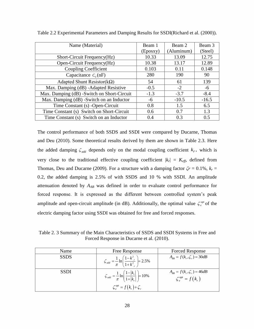
28
Table 2.2 Experimental Parameters and Damping Results for SSDI(Richard et al. (2000)).
Name (Material) Beam 1
(Eposxy)
Beam 2
(Aluminum)
Beam 3
(Steel)
Short-Circuit Frequency(Hz) 10.33 13.09 12.75
Open-Circuit Frequency(Hz) 10.38 13.17 12.89
Coupling Coefficient 0.103 0.11 0.148
Capacitance 0C (nF) 280 190 90
Adapted Shunt Resistor(kΩ) 54 61 139
Max. Damping (dB) -Adapted Resistive -0.5 -2 -6
Max. Damping (dB) -Switch on Short-Circuit -1.3 -3.7 -8.4
Max. Damping (dB) -Switch on an Inductor -6 -10.5 -16.5
Time Constant (s) -Open-Circuit 0.8 1.5 6.5
Time Constant (s) Switch on Short-Circuit 0.6 0.7 1.3
Time Constant (s) Switch on an Inductor 0.4 0.3 0.5
The control performance of both SSDS and SSDI were compared by Ducarne, Thomas
and Deu (2010). Some theoretical results derived by them are shown in Table 2.3. Here
the added damping add depends only on the modal coupling coefficient ,rk which is
very close to the traditional effective coupling coefficient |kr| =
Keff, defined from
Thomas, Deu and Ducarne (2009). For a structure with a damping factor ζr = 0.1%, kr =
0.2, the added damping is 2.5% of with SSDS and 10 % with SSDI. An amplitude
attenuation denoted by AAB was defined in order to evaluate control performance for
forced response. It is expressed as the different between controlled system’s peak
amplitude and open-circuit amplitude (in dB). Additionally, the optimal value opt
e of the
electric damping factor using SSDI was obtained for free and forced responses.
Table 2. 3 Summary of the Main Characteristics of SSDS and SSDI Systems in Free and
Forced Response in Ducarne et al. (2010).
Name Free Response Forced Response
SSDS 2
2
11ln 2.5%
1
r
add
r
k
k
( , ) 30dB r rA f k dB
SSDI 11ln 10%
1
r
add
r
k
k
opt
e r rf k
( , ) 46dB r rA f k dB opt
e rf k

29
Semi-active Control
Qiu, Ji and Zhu (2009a) reviewed the semi-active control performance, compared with
passive and active control. However, in their paper, and many others in the literature,
both ‘semi-passive’ and ‘semi-active’ control, or ‘adaptive’ or ‘hybrid’ control have been
used to represent various shunt damping circuits with external power sources. In this
chapter, an electric shunt circuit, is said to be semi-passive if and only if it does not
supply power to the system, otherwise, it belongs to semi-active.
Fleming and Moheimani (2003), developed an online adaptive shunt damping circuit for
multi-mode vibration control in the use of only one PZT patch. A voltage controlled
current source and DSP system was implemented by them to provide the desired terminal
impedance of an arbitrary shunt network. Their experimental testing for a randomly
excited simply supported beam showed reliable estimation of the performance functions,
optimal tuning of the circuit parameters, and satisfactory maladjustment. In addition, the
second and third modes of this beam were reduced in magnitude by up to 22dB and
19dB.
Moheimani (2003) presented an overview and discussion of the feedback analogy of
PZT-based resistive shunt damping systems. He investigated the similarities and
differences between shunt damping systems and collocated active vibration controllers.
He also demonstrated that the shunted vibration control problem using PZT-based
transducers is a very specific type of feedback control problem.
Petit et al. (2004) investigated the damping performance of SSD on small voltage sources
VSW (SSDV) in using Figure 2.6 (c), compared with Figure 2.6 (a) SSDS, and Figure 2.6
(b) SSDI. A specific control box detecting the maximum and minimum voltage V is used
to drive the switches. For the SSDV configurations, the capacitance of PZT
charges/discharges through the inductor. They derived the damping coefficient as a
function of the system electromechanical coupling coefficient and this indicated that for
SSDS and SSDI circuits, the damping capability was strongly related to the coupling
coefficient. Experiments were conducted on a cantilever beam and validated their
30
theoretical derivation. A clamped steel plate with a variable amount and location of PZT
was tested using a SSDI circuit for multi-mode operation over a very large frequency
band, since the PZT position and volume also affect the damping. Experimental results
showed that the SSDI circuit damped vibration (between 2dB to 9dB) at various modes
for frequencies lying between 180 Hz and 280 Hz.
Guyomar et al. (2005b) developed a probabilistic multi-modal SSDI control law
maximizing the energy dissipated in the nonlinear processing device connected to the
PZT. The voltage was able to reach a statistically probable value before processing the
piezo-voltage inversion, utilizing a probabilistic method. The numerical simulations
revealed that this probabilistic approach can optimize both displacement-based and
energy-based vibration control criteria. The optimized displacement and energy damping
were -8.5 dB and -6.3 dB compared to -3.0 dB and -4.3 dB respectively of a conventional
SSDI which switches on voltage extremes.
Lefeuvre et al. (2006) added two voltage sources in the switch schemes from Figure 2.7
(d) to significantly reduce the required quantity of the PZT-based transducers. Their
experiments demonstrated an 83% reduction of the PZT volume by adding two voltage
sources of 10 V each in the switching circuit, while effecting the same vibration
attenuation of -24dB. Badel et al. (2006c) and Lallart, Badel and Guyomar (2008a) found
out if the external driving force is lower than the force induced by the PZT-based
transducer, the SSDV control becomes unstable. This problem was solved by them
through adjusting the voltage source to fit the piezoelectric generated control force to the
mechanical excitation. Guyomar, Lallart and Monnier (2008) implemented a SSDV with
single voltage source for structural stiffness control.
Guyomar, Richard and Mohammadi (2007) analyzed the voltage/displacement signal
during a given time period to statistically determine the probable voltage/displacement
thresholds using SSDI technique. The experiments revealed that either a probability or
statistical strain analysis could allow defining a criterion to identify the relevant switch
instants more accurately. The best results could be received using either the strain itself
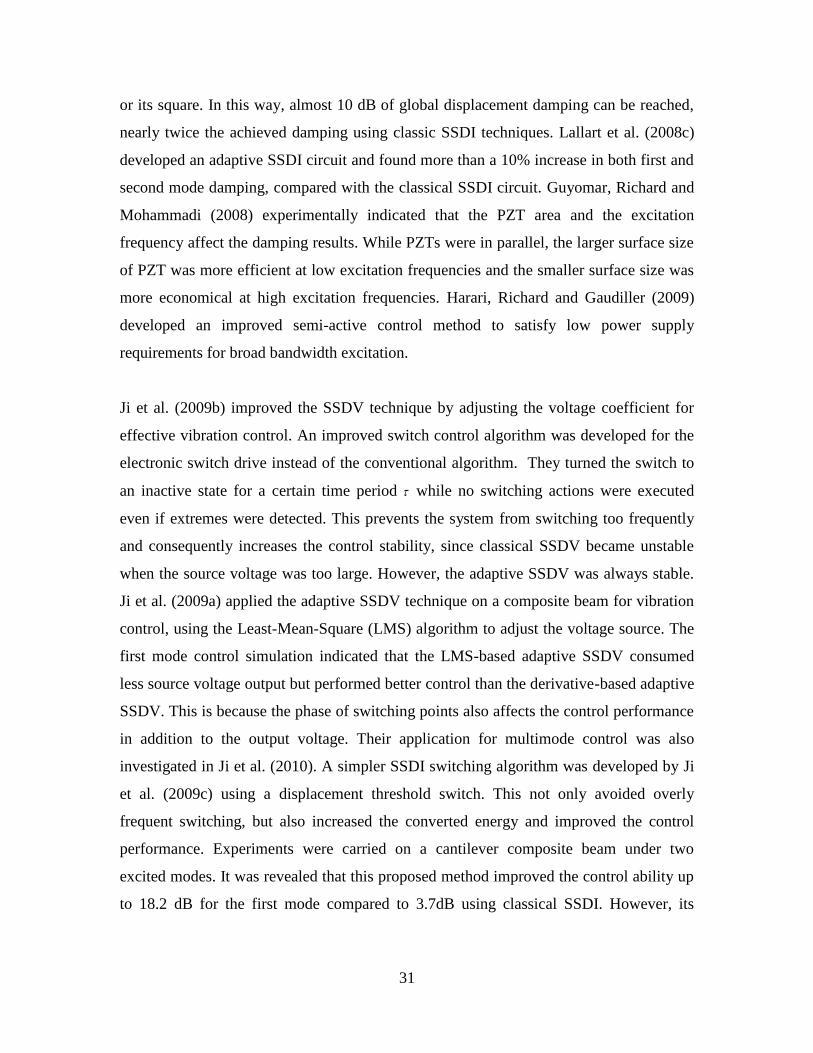
31
or its square. In this way, almost 10 dB of global displacement damping can be reached,
nearly twice the achieved damping using classic SSDI techniques. Lallart et al. (2008c)
developed an adaptive SSDI circuit and found more than a 10% increase in both first and
second mode damping, compared with the classical SSDI circuit. Guyomar, Richard and
Mohammadi (2008) experimentally indicated that the PZT area and the excitation
frequency affect the damping results. While PZTs were in parallel, the larger surface size
of PZT was more efficient at low excitation frequencies and the smaller surface size was
more economical at high excitation frequencies. Harari, Richard and Gaudiller (2009)
developed an improved semi-active control method to satisfy low power supply
requirements for broad bandwidth excitation.
Ji et al. (2009b) improved the SSDV technique by adjusting the voltage coefficient for
effective vibration control. An improved switch control algorithm was developed for the
electronic switch drive instead of the conventional algorithm. They turned the switch to
an inactive state for a certain time period while no switching actions were executed
even if extremes were detected. This prevents the system from switching too frequently
and consequently increases the control stability, since classical SSDV became unstable
when the source voltage was too large. However, the adaptive SSDV was always stable.
Ji et al. (2009a) applied the adaptive SSDV technique on a composite beam for vibration
control, using the Least-Mean-Square (LMS) algorithm to adjust the voltage source. The
first mode control simulation indicated that the LMS-based adaptive SSDV consumed
less source voltage output but performed better control than the derivative-based adaptive
SSDV. This is because the phase of switching points also affects the control performance
in addition to the output voltage. Their application for multimode control was also
investigated in Ji et al. (2010). A simpler SSDI switching algorithm was developed by Ji
et al. (2009c) using a displacement threshold switch. This not only avoided overly
frequent switching, but also increased the converted energy and improved the control
performance. Experiments were carried on a cantilever composite beam under two
excited modes. It was revealed that this proposed method improved the control ability up
to 18.2 dB for the first mode compared to 3.7dB using classical SSDI. However, its

32
control performance dropped to 2.6 dB from 3.46 dB using classical SSDI for the second
mode when the first and the second modes were excited simultaneously.
Wilhelm and Rajamani (2009) presented a multimode vibration control law by using the
harvested and stored electrical charge from mechanical vibration. They proposed to
employ an array of one or more pre-charged capacitors to provide a selection of various
power supplies. The external capacitors can supply a control voltage to the PZT-based
actuators and can also collect current generated by the PZT-based actuators. In their
paper, the SSDI method was compared with the Single Switched Capacitor (SSC), and
the Multiple Switched Capacitor (MSC) method. The SSDI cannot harvest and store
energy continuously, which led to inferior performance as a self-powering semi-active
method. The SSC method could suppress vibration while harvesting and storing energy
continuously, but its single mode nature limited its control effectiveness. The MSC
method was more effective in both transient and continuous random excited vibration
excitation while harvesting over 20% of the ambient vibration energy.
Active Control
Considerable research on active control laws for the low frequency vibration reduction in
flexible structures has been conducted. Wagg and Neild (2010) investigated
interrelationships of nonlinear vibration identification, modeling and control in the
following separate, but related areas: nonlinear vibrations, nonlinear control, approximate
methods, cables, beams, plates and shells. The focus reported here is motivated by
searching for vibration suppression laws that use a minimum amount of energy, with the
idea that they might eventually be powered off of harvested energy and/or low power
storage devices. Bardou et al. (1997) analytically compared different active control
strategies of minimizing the total power supplied to a plate. They focused on physical
parameter optimization of the plate and locations of the excitation forces. Anthony and
Elliott (2000) investigated how the positions of the controlling actuators affect the control
performance in reducing the total vibration energy. Of four cost functions they studied,
two are energy-based, and the other two are based on velocity measurements. However,
the success of optimal active control is also dependent upon increasing demands on

33
design specifications in order to obtain improved performance and robustness
characteristics from structural control systems. Crawley and de Luis (1987) proposed to
build piezoelectric materials in laminated beams. Baz and Poh (1988) utilized a modified
independent modal space control for selecting optimal location, control gains and
excitation voltage of the PZT-based actuators, in order to reduce input control effort for
vibration suppression of large flexible structures. Morgan and Wang (1998) synthesized a
simple parametric control law involving an inductive shunt circuit to turn the resistor on
and off for reducing control power (a resonant inductive shunt circuit suppresses the
vibration equivalent to a tuned mass damper). Phan, Goo and Park (2009) developed a
genetic algorithm for parameter optimization of a Positive Position Feedback (PPF)
controller, in order to minimize the energy consumption in vibration suppression of a
flexible robot manipulator.
However, conventional optimal control methods calculate energy consumption only
indirectly by adjusting a weighting matrix on control effort, see Preumont (2002) and
Inman (2006) for instance. With minimizing actuation power in mind, motivated by
noting that the actuation voltage in most active vibration suppression control laws is
relatively high during the early control periods. Thus voltage saturation was found to be
very effective in reducing actuation power and obtaining the same performance. Wang
and Inman (2011a) introduced a reduced energy control law, employing a saturation
control logic to switch a control system from one state to another, which will be
introduced in next chapter. A reduced energy control is achieved by providing the
conventional active controllers with a limited voltage boundary.
CHAPTER SUMMARY
The main objective of this chapter is to review methods on how to suppress vibration
using harvested energy from ambient mechanical vibrations via PZT-based transduction.
First, the existing equivalent electromechanical modeling methods are reviewed for
vibration-based cantilevered energy harvesters using PZT-based transducers. Following
the literature of mathematical and dynamical modeling of these devices ranging from
lumped to distributed parameter base excitation problems, the commonly used electrical

34
power conditioning circuits and their optimization are presented and discussed. The
energy dissipation caused structural damping leads to the concept of purely passive shunt
damping. Classified by whether external power is supplied to the structures, this chapter
reviews the literature of vibration control laws along the lines of purely passive, semi-
passive, semi-active, and active control. Special attention is given on recent articles
investigating semi-passive and semi-active control strategies derived from synchronized
switching damping (SSD). This chapter also reviews the existing optimal active control
methods aiming for less control energy consumption. The aim of this review is to provide
background for researching the concept of using harvested energy as the main source of
powering control systems for the purpose of suppressing vibrations. The eventual goal is
to answer the question of whether or not harvested ambient energy can be used to provide
enough control effort to provide a reasonable level of vibration suppression and to
quantify the degree to which such control can be accomplished. One element of such
research is to develop minimum energy control laws as well as means of maximizing the
amount of energy harvested.

35
CHAPTER 3 REDUCED ENERGY CONTROL LAW
The chapter presented here examines four conventional vibration suppression control
laws and four hybrid modifications of these laws using a switching method, named as
Reduced Energy Control (REC). The motivation is to determine which of these eight
controllers results in the least amount of power flow to the actuator to have the same
settling time under free vibrations. The motivation to consider REC is the idea that in
some applications very little energy is available for control, yet passive, semi-passive or
semi-active methods cannot meet performance demands. In particular the eventual goal is
to reduce transient vibrations of smart structures using energy obtained from harvesting
and/or low power storage devices (batteries or super capacitors) as is often desirable in
aerospace systems. The four conventional active control systems compared in this work
are Positive Position Feedback (PPF) control, Proportional Integral Derivative (PID)
control, nonlinear control, and Linear Quadratic Regulator (LQR) control. A hybrid
version of each controller is obtained by implementing a bang-bang control law (on-off
control). The bang-bang control algorithm switches the control voltage between an
external voltage supply and the feedback signal provided by the PPF, PID, nonlinear or
LQR controllers. The purpose of combining the bang-bang control law with the
aforementioned controllers is to reduce the power requirement for vibration suppression
by providing an active controller with limited voltage input. Free vibrations of a thin
cantilevered beam with a piezoceramic transducer are controlled by these eight
controllers with a focus on the fundamental transverse vibration mode. Experimental
results exhibit that the system with hybrid bang-bang-nonlinear controller requires 67.3
% less power than its conventional version. The hybrid versions require significantly less
power flow as compared to their conventional counterparts for the PPF, PID and LQR
controllers as well. Experiments also reveal the presence of substantial piezoelectric
nonlinearities in the transducer. The voltage-dependent behavior of the electromechanical
coupling coefficient is identified empirically and represented by a curve-fit expression. A
real-time state variable control algorithm is developed to account for the voltage-
dependent behavior of the coupling coefficient, enabling good agreement between the
simulation and experimental results.

36
NOMENCLATURE
, , , curve fit constants-describing the nonlinear piezoelectric behavior
state matrix in the state space representation
system constant determined by initial condi
f f f f
s
a b c d
A
A
tions and damping characteristics
nonlinear gain for the nonlinear controller
input matrix in the state space representation
electromechanical coupling coefficient f
nlA
B
b
33
eedback constant of the controller
output matrix in the state space representation
throughput matrix in the state space representation
longitudinal piezoelectric cons
C
D
d
tant of the piezoelectric material
state feedback gain for the LQR controller
control gain of the PPF controller
position of the MFC bottom layer
position
f
c
d
G
g
h
h
of the MFC top layer
total thickness of the MFC
total width of the MFC
actuation current
cost index function for the LQR controller
propor
p
t
p
h
h
i
J
k
tional gain of the PID controller
integral gain of the PID controller
derivative gain of the PID controller
active beam length
number of electrode pairs
i
d
e
k
k
l
N
over the active beam length
unique positive semi definite solution to the algebraic Riccati Equation
Quadratic matrices of the LQR controller
Regulator matrices of
P
Q
R
0
the LQR controller
average actuation power measured
instantaneous actuation power measured
width of each electrode of MFC in the longitude beam axis
w
avg
ins
e
P
P
r
r
idth of each non-electrode region of MFC in the longitude beam axis
Laplace transform complex argument
time
time constantc
s
t
t

37
settling time
control input actuation voltage
external voltage supply of the bang-bang-PPF controller
tip displacement of the beam
el
s
ext
p
T
u
V
X
Y
astic modulus of piezoelectric device MFC
generalized natural frequency of the PPF controller
fundamental un damped natural frequency of the beam with a tip mass
f
n
1
viscous damping ratio of the beam for the fundamental mode
generalized damping ratio of the PPF controller
mass normalized eigenfunction of the cantilevered beam for
f
the first mode
INTRODUCTION
Piezoelectric materials produce an electric field when strained, which is used for sensing
and energy harvesting, and produce a mechanical strain when an electric field is applied,
which is used for actuation and vibration control. Due to their mechanical simplicity,
light weight, small volume, and ability to be easily integrated into applications with
flexible structures, piezoelectric materials have found many applications in vibration
control. The increased research in energy harvesting offers promise in developing purely
passive, semi-passive and semi-active control systems that run using the harvested energy
(Wang and Inman (2010)). For instance, Makihara, Onoda and Minesugi (2005) proposed
a hybrid method integrating a bang-bang active method with an energy-recycling
technique (similar to SSDI reviewed in chapter 2), thus recycling the converted electrical
energy harvested via piezoelectric material from mechanical vibrations. Ji et al. (2011b)
analyzed converted energy numerically and experimentally to improve control
performance using SSD based on a displacement switching threshold. Ji et al. (2011c)
theoretically and numerically investigated modal coupling induced by energy conversion
using SSD. Liang and Liao (2009) studied the structural damping capacity by analyzing
the energy dissipated during the energy harvesting in the application of SSHI and
summarized that the damping capacity can be improved by increasing the
electromechanical coupling coefficient and/or enhancing the electrical quality factor. In
the experimental application of SSHI, Badel et al (2006) reported a 15dB amplitude

38
reduction of the beam tip displacement under harmonic force with the amplitude of
0.086N around its fundamental resonance frequency of 56Hz. However, due to the nature
of the low frequency of the fundamental mode, the light weight, typically for space
structures, as well as the limitation of electromechanical coupling of piezoelectric
materials, the maximum amplitude reduction for transient vibration case in the use of
SSHI is unable to reach 26dB (20lg(5%)), with reasonable inductance.
Our motivation is to develop energy-autonomous controllers powered by harvested
ambient energy using piezoceramic materials. The objective of this chapter is to compare
different active control laws to suppress low-frequency vibrations using reduced
actuation energy for the same system and under the same design constraint (identical
settling time Ts2
for free vibrations). We investigated the actuation power flow of four
conventional control systems as well as their hybrid versions employing a switching
technique. They are the PPF control (Fanson and Caughey (1990) and Goh (1983)). the
Proportional Integral Derivative (PID) control, see O'Dwyer (2009) for example, a
nonlinear control with a second-order nonlinear term of a product of the position and the
velocity feedback to create variable damping (Lewis (1953) and Lee and Castelazo
(1987)), the Linear Quadratic Regulator (LQR) control, summarized by Levine (1996)
and Dorf and Bishop (2008), as well as their hybrid versions integrating a bang-bang
control law (on-off control). Bang-bang control, usually employed to switch a control
system from one state to another, is a strategy typically used for optimal time problems
(Hermes and LaSalle (1969)). However, in this chapter, a bang-bang control algorithm is
implemented to switch a control input from an external voltage supply to the feedback
signal provided from the PPF, PID, nonlinear or LQR controllers. The purpose of
combining the bang-bang control law with the aforementioned controllers is not to obtain
minimum time but to reduce the actuation power requirement for vibration suppression.
It is known that the electromechanical coupling coefficient of a piezoelectric transducer
(feedback constant in the control problem) depends on the beam structure and the
2 The settling time is defined in this work as the time to reach 5% of the initial displacement in the
absence of any initial velocity.

39
piezoelectric actuator. Most researchers, such as Corr and Clark (2001a) and Onoda,
Makihara and Minesugi (2003), estimate this coefficient experimentally as a constant.
However, it is known that the electromechanical properties of piezoelectric materials
exhibit nonlinearity at high electric fields, see reference in Taylor (1985) and Uchino,
Negishi and Hirose (1989). This nonlinearity results in a considerable discrepancy
between the experimental measurements and simulation results if constant (voltage-
independent) coupling coefficient is assumed. Therefore, in this work, the
electromechanical coupling coefficient (feedback constant) is identified empirically by
using the results of the first experimental case. An exponential function of the voltage-
dependent coupling coefficient (feedback constant) is then obtained by curve fitting. A
state variable control algorithm is developed to account for the identified nonlinearity of
the coupling coefficient with control voltage in the simulations.
CONVENTIONAL ACTIVE CONTROL SYSTEMS
To compare control laws in terms of the required actuation power, it is emphasized that
they all designed to yield the same performance. In this case, we design each controller to
have the same setting time and each is given the same initial displacement and zero initial
velocity. Four conventional controllers and their hybrid bang-bang versions (REC) are
designed and compared in terms of the same settling time constraint. The free vibration
on the single degree of freedom mechanical system is considered here. The governing
equation of motion with small oscillations derived from equation (2.1) can be simplified
as:
22 0.n nx x x (3.1)
Here, x is the displacement response of the single degree of freedom system (the
transverse tip displacement of the cantilever in the experimental section introduced later
on), ζ and ωn are the viscous damping ratio and the undamped natural frequency of the
structural fundamental mode, respectively. The Laplace transform of this open-loop
system with the initial displacement x0 and zero initial velocity gives:

40
2 2
0 0( ) 2 ( ( ) )) ( ) 0.
n ns X s sx sX s x X s (3.2)
Here, X(s) denotes a Laplace transform of x (t), and s is the transformation complex of t.
The displacement response in Laplace domain then becomes:
0 0
2 2
2( ) ,
2
n
n n
x s xX s
s
(3.3)
and the time domain response becomes:
2
2 1 1( ) sin( 1 tan ).n
t
s nx t e tA
(3.4)
Here, As is the system constant determined by initial conditions and damping
characteristics. Thus the open-loop settling time can be derived as (examples can also be
found in Inman (2007)):
.
n
Open csT
t
(3.5)
Here, tc is the time constant. Its value is -ln5% (approximately 3) based on the definition
of settling time used here.
PPF Control
The first consideration is the PPF control methodology. PPF is popular for vibration
reduction since it offers rapid damping for a specific mode, is very stable, and is not
sensitive to spillover. It has been extensively applied in micro-vibration control of space
structures (Vaillon and Philippe (1999)), in suppressing thermally induced vibrations (
Friswell, Inman and Rietz (1997)), and for slewing flexible frames (Leo and Inman
(1994)). As illustrated in Figure 3.1(a), the PPF control algorithm introduces a second-
order filter G to the piezoelectrically coupled beam system H, which is fed back by the

41
sensed position signal. The position response of the filter is then fed back as a force input
to the structure. The PPF controller equation for the scalar case is given by:
2 22 .f f f f fu u u g x (3.6)
Here, u denotes the control input (actuation voltage), ζf and ωf are the generalized
damping ratio and the natural frequency of the controller respectively and gf is the control
gain. Note that the PPF controller is composed of a second order filter, the same form as
the structural equation but with much higher damping ratio (about 50 times higher in this
work to satisfy the settling time requirement). The transfer function of the PPF controller
in Laplace domain is given by:
2
2 2( ) .
2
f f
PPF
f f f
gG s
s s
(3.7)
The governing equations of the PPF closed-loop system, in free vibrations can be
expressed as:
2 2
2 2
2 0 0.
0 2 0
n n f f
f f f f f
gx x x
gu u u
(3.8)
In order to check system stability, Fanson and Caughey (1990) constructed a Lyapunov
function, and concluded that the PPF control system is stable if the determinant of
displacement coefficient matrix is positive, that is, if the following condition is satisfied:
2 2 2.f f ng (3.9)
The tip displacement response derived from equation (8) takes the following form:
1 12
1 1 1 21( ) sin( ) ( ).
t
fx t Ae t f
(3.10)

42
Here A1 and φ1 are system constants determined by initial conditions and damping
characteristics. ζ1 is the closed-loop damping ratio approximated to be ζf. The natural
frequencies of the PPF control system (ignoring damping effects) are the square roots of
the eigenvalues of characteristic polynomial of the mass normalized stiffness matrix:
2 2 2 2 2 4 2
2
1
2 2 2 2 2 4 2
2
2
( ) 4,
2
( ) 4
2.
n f n f f f
n f n f f f
g
g
(3.11)
Note that the natural frequency and damping ratio of the PPF control system 1 and ζ1 are
different from that of the open loop system n .The settling time and the relationship of
natural frequencies of PPF control system is of the form:
1 1
.PPF c
s
tT
(3.12)
PID Control
Next consider a PID control law, which remains an important control tool, due to its
simplicity and robust performance. The success of implementing the PID controller
depends on the appropriate choices of the PID gains. The transfer function of the PID
controller in Laplace domain is given by:
( ) ,i
PID p d
kG s k k s
s (3.13)
where, the proportional control gain kp is proportional to the size of the process error
signal, the integral control gain ki offers control correction by eliminating offset from a
constant reference signal value in the final state, and the derivative control gain kd uses
the rate of change of an error signal to predict the control action and tends to increase the

43
stability of the system. Since the effective damping coefficient of the PD control system
is thus: 2 ,n d
k rather than 2n
, and the settling time of the PID control system is thus
estimated to be:
.0.5
c
n d
PID
s
tT
k
(3.14)
However, the integral control gain ki may slowly decrease the amplitude. A MatLab code
is created and used to optimize these parameters in order to achieve the desired settling
time.
Nonlinear Control
The following consideration is a nonlinear control law. It has been shown that the system
response can be improved by constructing a nonlinear variable damping (using the
product of position and velocity), which eliminates overshoot (Castelazo and Lee
(1990)), improves the settling time, provides better system response than an optimal
linear controller (Rietz and Inman (2000)), and enhances robustness (Kuo and Wang
(1990)). In this chapter, this type of nonlinear controller is implemented by building a
position times velocity feedback and using a PD controller as the basis. The closed-loop
system is represented by:
2(2 | |) )( 0,n d nl n px k k x x k x (3.15)
where knl denotes the nonlinear gain. One should note that the position x in the damping
term could introduce negative damping to the system, which can lead to an unstable
response. Therefore the absolute value of position feedback is employed to avoid
negative damping. The effective damping coefficient of the nonlinear control is
approximately:( 0.5 )
2 n dk
n d nl nlk k A e
. The settling time is thus estimated by:

44
( 0.5 )/ ( 0.5 0.5 ).
n d nl nl
n dNL k
s cT k k At e
(3.16)
Here, Anl is the envelop amplitude determined by initial conditions and the system
damping characteristics. A MatLab code is created to validate and optimize these
estimated parameters in order to achieve the desired settling time.
LQR Control
The last conventional controller considered is the standard formulation of an LQR
optimal controller. The single input single output (SISO) control system from equation
(1) is:
22 ,n nx x x bu (3.17)
The state-space representation of this SISO system can be expressed as:
,
.
X AX BU
Y CX DU
(3.18)
Here, the state matrix A=[0,1;-ωn2, -2ζωn], the input matrix B=[0;b], b is the
electromechanical coupling coefficient (feedback constant) of the system. The output
matrix C = [1,0], and the throughput matrix D = [0]. The state vector X = [x; dx/dt], input
vector U = [u], and thus the output vector Y = [x].
The LQR approach entails the solution of an algebraic Riccati equation to obtain state
feedback gain G of the Linear Time Invariant system:
( ) ( ).Gu t x t (3.19)
The state feedback gain G is optimized to minimize the following cost (index) function:

45
0[ ( ) ( ) ( ) ( ) ( ) ( )] ,
s TT
TJ x Q x u R u d (3.20)
where the given constant penalty (weighting) matrices Q and R are all symmetric, with Q
positive semi definite and R positive definite. Choosing Q large relative to R means that
the response attenuation or minimal response will be more heavily penalized than the
control effort, and vice versa. In this chapter, the matrix Q is chosen as identity and the
scalar matrix R is tuned to be much larger to obtain the desired settling time with
reasonable control effort, while guaranteeing saturation-free control for a series of control
inputs. The minimized control input is:
1.
TG R B P
(3.21)
Here P is the unique positive semi-definite solution to the algebraic Riccati equation:
10.
T TA P PA PBR B P Q
(3.22)
An analytical expression for the settling time for a LQR controller was not found, but
numerical iteration is used in the design to satisfy the settling time constraint. Note that
each of the above controllers is designed to have the same settling time, but that each
design has a different closed loop frequency or/and damping ratio determined by the
controller dynamics. Equations (3.12), (3.14) and (3.16) are not used directly to design
for the same settling time as they are not exact, but rather they are presented to punctuate
the fact the different control laws can have the same settling time but with different
damping, and hence different actuation power dissipation because the controllers induce
different frequency shifts. Therefore each controller will consume a different amount of
actuation energy.
HYBRID BANG-BANG CONTROL SYSTEMS
Motivated by noting that the actuation voltage in most vibration suppression control laws
is relatively high during the early control periods, a bang-bang voltage clipping algorithm
which reduces the large amount of actuation power consumed in the early periods, is
examined to see if the total actuation power to obtain the same performance is possible.
Bang-bang control is usually employed to switch a control system from one state to
another. In this chapter, a bang-bang control algorithm is used to switch a control source

46
from the external voltage supply (constant) to a feedback signal from each conventional
controller. The purpose is not to obtain minimum time but minimum actuation power
requirement for vibration suppression. This objective is achieved by providing the
conventional controllers with a limited voltage boundary. The comparisons of the
conventional and hybrid single input single output feedback control systems are
schematically illustrated in Figure 3.1(a) and (b) respectively.
(a) (b)
Figure 3.1 Block diagrams of the (a) conventional and (b) hybrid control system.
Unlike a continuous feedback control law, the bang-bang method has a control threshold
value Vext. A switch position is changed between P1 and P2 to select the input control
signal, according to the following control logic:
When ( )u t > 0:
if ( )u t <Vext , connect to P1, input voltage u= ( )u t ; if ( )u t ≥Vext , connect to P2, input
voltage u=Vext ;
When ( )u t <0:
if ( )u t ≤Vext , connect to P2, input voltage u= Vext ;if ( )u t >Vext , connect to P1, input
voltage u= ( )u t .
This control logic sets up an upper and a lower bound on the voltage, in order to limit the
control input provided by the each conventional controller. The switch connects to the
external power supply if the input voltage reaches the limit value, and connects back to
the conventional controller once it drops in between the limits. Therefore, the logic is
Hu(t) x(t)
active
controllerG
+
r(t)beam w/ MFC
Hx(t)
active
controller
Vext
P1
P2
bang-bang
beam w/ MFC
G
r(t) u(t)
+

47
employed to control the switch in order to reduce the control input ( )u t when ( )u t is
positive, and increase it when ( )u t is negative. In this way, the electric current flows in
the desired circuit (P1 or P2 in Figure 3.1(b)) while vibration is suppressed more
effectively.
Experimental Results
The mechanical system of interest is a flexible cantilevered aluminum beam, controlled
in turn by each of the eight controllers studied in this work, with a focus on the
fundamental transverse vibration mode. Figures 3.2(a) and 3.2(b) show a picture and a
schematic diagram of the experimental setup, respectively. An aluminum beam, with an
MFC (Macro-Fiber Composite, originally developed by Wilkie et al. (2000) in NASA
Langley Research Center) patch attached to its root, is mounted vertically on an isolated
block. A magnetic tip mass is rigidly attached to the free end of the beam in order to
create an identical initial displacement condition for all the controllers, by means of an
electronically controlled electromagnet. This magnet (not shown in Figure 3.2(a) or (b))
is placed 4.8mm away from the tip mass allowing a repeatable release of the beam from a
fixed displacement with zero initial velocity.
(a) (b)
Figure 3.2 (a) Picture and (b) schematic diagram of experimental setup.
The tip displacement signal, measured with a MTI LTC-50-20 displacement laser sensor,
is low-pass filtered and fed into the controller. The control signal is low-pass filtered,
amplified 200 times with a TREK 2220 amplifier and fed back to the MFC actuator. The
dSPACE Board
Filter
Amplifier
Displacement Sensor
Tip Mass
Aluminum Beam
MFC
PC
Fixture
MFC
Beam
Fixture
Tip Mass
TREK Amp.
LPFilter
dSPACE Board
PC w/Simulink/Control Desk
Disp. SensorLP
Filter

48
control scheme in Matlab Simulink is implemented using the Control Desk software and
a dSPACE 1005 real time control board. The physical properties of the aluminum beam
are illustrated in Table 3.1. The MFC patch consists of rectangular piezoceramic rods
sandwiched between layers of adhesive and electrode polyimide film, with lateral
expanding motion and a collocated sensor Type S1. This film contains interdigitated
electrodes that transfer the applied voltage directly to and from the fibers of the
rectangular cross-section. Electrical impedance spectroscopy from 0.1 Hz to 100 kHz of
the MFC8528-P1 actuator by Bilgen, Wang and Inman (2011) showed that the
capacitance of MFC (4.05nF) is very low and remains constant during low frequency
band (0.1 Hz to 100 Hz). Their results also show that the MFC has the best control
effectiveness, compared with PSI PZT-5A, PSI PZT-5H, MIDE QP10N, due to its large
control authority (±500V voltage allowance) as a result of its larger d33 value.
Table 3.1Properties of the Beam and the Piezoelectric Transducer (MFC).
Physical property Value
Beam length x width 450mm x 28mm
Beam thickness 3.05mm
Beam mass M + tip mass Mt 139.4g+12g
MFC piezoelectric constant, strain/applied field d33 460(pm/V)
A single mechanical degree of freedom model (Equation (3.1)) is used here considering
only the fundamental vibration mode of the distributed-parameter model. The natural
frequency of the fundamental transverse vibration mode was experimentally identified as
12.0 Hz, using a Frequency Response Function (FRF) obtained from the Siglab. The
damping ratio was calculated as ζ=0.0037, using the quadrature peak picking on the FRF
plot.
Figure 3.3 shows the beam tip displacement for (a) the open-loop system with short-
circuit conditions (without feedback controllers), for (b) the PPF and the bang-bang-PPF
control system, for (c) the PID and the bang-bang-PID control system, for (d) the
nonlinear and bang-bang-nonlinear control system and for (e) the LQR and the bang-
bang-LQR control system. In all cases, the initial tip displacement is 4.8mm and the

49
initial tip velocity is zero.
Figure 3.3 Tip displacement measurements of the (a) Open-loop (b) PPF, Bang-bang-PPF
(c) PID, Bang-bang-PID (d) Nonlinear, Bang-bang-nonlinear (e) LQR, Bang-bang-LQR
control systems with identical initial conditions.
The settling time for the open-loop time response is 10.9s. The settling time for all the
control systems are all reduced to 0.85s as a design constraint (which is 92% of the open-
loop settling time). This design constraint is determined by the fastest response time for
all the conventional control systems under the largest actuation authority of MFC (-
500V~+500V). The parameters of each controller are tuned specifically to reach the same
settling time constraint. Figure 3 also illustrates that the conventional controls tend to
apply large forces to suppress vibration response to the final state (zero in this case), thus
using lots of energy early on. The hybrid control prevents this by limiting how much
control effort is expended in the early time intervals when the difference between the
initial state and final is large. Figure 3.4 compares the experimental time histories of the
control voltage of (a) PPF (solid line) and Bang-bang-PPF control system (dashed line);
(b) PID (solid line) and Bang-bang-PID (dashed line) control system; (c) Nonlinear (solid
line) and Bang-bang-nonlinear (dashed line) control system; (d) LQR (solid line) and
Bang-bang-LQR (dashed line) control system.
0 0.2 0.4 0.6 0.8 1 1.2 1.4 1.6 1.8 2-5
0
5
Time(s)--(a)
Dis
p.(
mm
)
0 0.5 1 1.5 2-5
0
5
Time(s)--(b)
Dis
p.(
mm
)
0 0.5 1 1.5-5
0
5
Time(s)--(c)
Dis
p.(
mm
)
0 0.5 1 1.5 2-5
0
5
Time(s)--(d)
Dis
p.(
mm
)
0 0.5 1 1.5 2-5
0
5
Time(s)--(e)
Dis
p.(
mm
)
Open-loop
PPF
Bang-bang-PPF
PID
Bang-bang-PID
Nonlinear
Bang-bang-nonlinear
LQR
Bang-bang-LQR

50
Figure 3.4 Experimental actuation voltage histories for the (a) PPF, Bang-bang-PPF (b)
PID, Bang-bang-PID (c) Nonlinear, Bang-bang-nonlinear (d) LQR, Bang-bang-LQR
control systems with identical initial conditions.
Figure 3.5 shows time-domain control current measurements of (a) PPF (solid line) and
Bang-bang-PPF control system (dashed line); (b) PID (solid line) and Bang-bang-PID
(dashed line) control system; (c) nonlinear (solid line) and Bang-bang-nonlinear (dashed
line) control system; (d) LQR (solid line) and Bang-bang-LQR (dashed line) control
system.
Figure 3.5 Experimental actuation current histories for the (a) PPF, Bang-bang-PPF (b)
PID, Bang-bang-PID (c) Nonlinear, Bang-bang-nonlinear (d) LQR and Bang-bang-LQR
control systems with identical initial conditions.
0 0.2 0.4 0.6 0.8 1-500
0
500
Time(s)(a)
Vo
ltag
e(V
)
0 0.2 0.4 0.6 0.8 1-500
0
500
Time(s)(b)
Vo
ltag
e(V
)
0 0.2 0.4 0.6 0.8 1-500
0
500
Time(s)(c)
Vo
ltag
e(V
)
0 0.2 0.4 0.6 0.8 1-500
0
500
Time(s)(d)
Vo
ltag
e(V
)
PPF
Bang-bang-PPF
PID
Bang-bang-PID
Nonlinear
Bang-bang-nonlinear
LQR
Bang-bang-LQR
0 0.2 0.4 0.6 0.8 1
-0.5
0
0.5
Time(s)(a)
Cu
rre
nt(
mA
)
0 0.2 0.4 0.6 0.8 1
-0.5
0
0.5
Time(s)(b)
Cu
rre
nt(
mA
)
0 0.2 0.4 0.6 0.8 1
-0.5
0
0.5
Time(s)(c)
Cu
rre
nt(
mA
)
0 0.2 0.4 0.6 0.8 1
-0.5
0
0.5
Time(s)(d)
Cu
rre
nt(
mA
)
PPF
Bang-bang-PPF
PID
Bang-bang-PID
Nonlinear
Bang-bang-nonlinear
LQR
Bang-bang-LQR
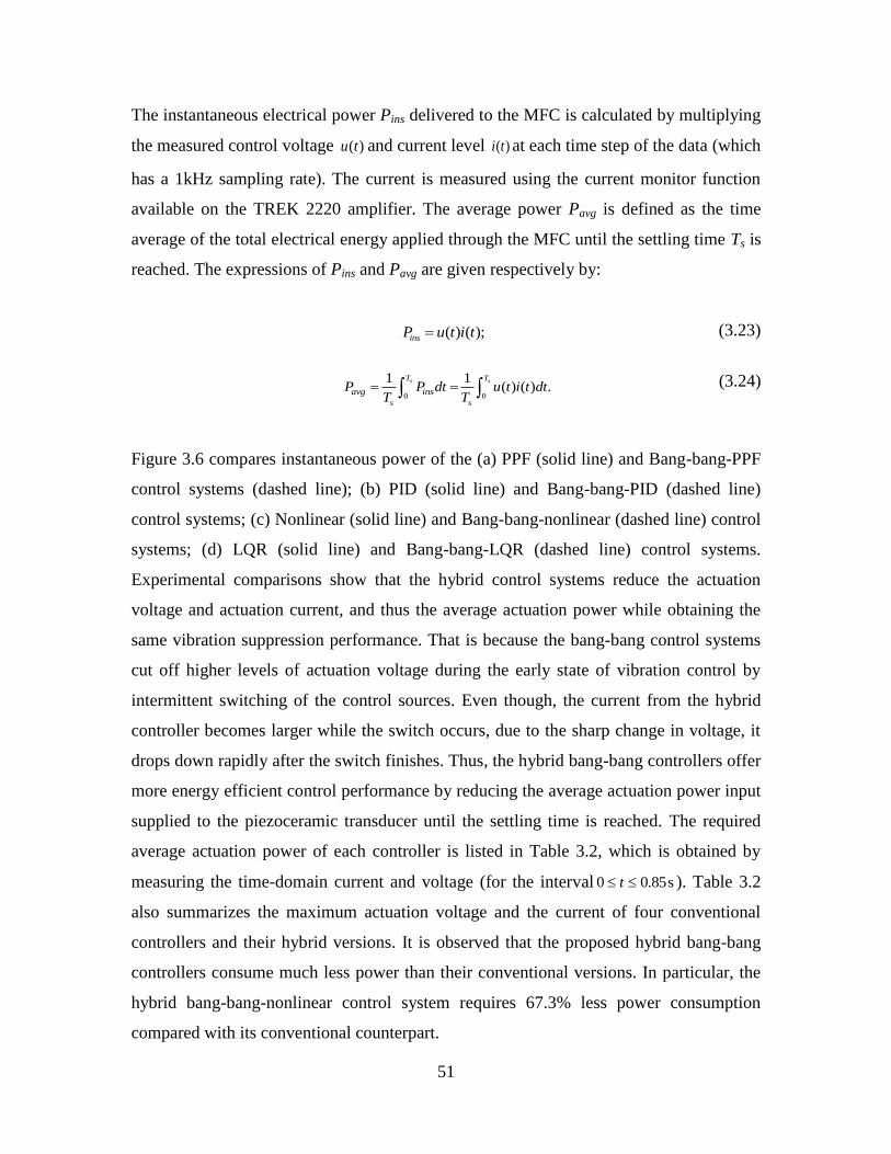
51
The instantaneous electrical power Pins delivered to the MFC is calculated by multiplying
the measured control voltage ( )u t and current level ( )i t at each time step of the data (which
has a 1kHz sampling rate). The current is measured using the current monitor function
available on the TREK 2220 amplifier. The average power Pavg is defined as the time
average of the total electrical energy applied through the MFC until the settling time Ts is
reached. The expressions of Pins and Pavg are given respectively by:
( ) ( );insP u t i t (3.23)
0 0
1 1( ) ( ) .
s sT T
s s
avg insP P dt u t i t dtT T
(3.24)
Figure 3.6 compares instantaneous power of the (a) PPF (solid line) and Bang-bang-PPF
control systems (dashed line); (b) PID (solid line) and Bang-bang-PID (dashed line)
control systems; (c) Nonlinear (solid line) and Bang-bang-nonlinear (dashed line) control
systems; (d) LQR (solid line) and Bang-bang-LQR (dashed line) control systems.
Experimental comparisons show that the hybrid control systems reduce the actuation
voltage and actuation current, and thus the average actuation power while obtaining the
same vibration suppression performance. That is because the bang-bang control systems
cut off higher levels of actuation voltage during the early state of vibration control by
intermittent switching of the control sources. Even though, the current from the hybrid
controller becomes larger while the switch occurs, due to the sharp change in voltage, it
drops down rapidly after the switch finishes. Thus, the hybrid bang-bang controllers offer
more energy efficient control performance by reducing the average actuation power input
supplied to the piezoceramic transducer until the settling time is reached. The required
average actuation power of each controller is listed in Table 3.2, which is obtained by
measuring the time-domain current and voltage (for the interval 0 0.85st ). Table 3.2
also summarizes the maximum actuation voltage and the current of four conventional
controllers and their hybrid versions. It is observed that the proposed hybrid bang-bang
controllers consume much less power than their conventional versions. In particular, the
hybrid bang-bang-nonlinear control system requires 67.3% less power consumption
compared with its conventional counterpart.
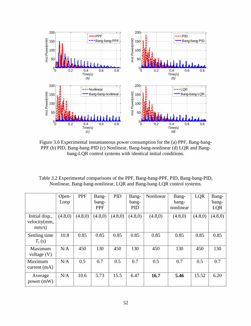
52
Figure 3.6 Experimental instantaneous power consumption for the (a) PPF, Bang-bang-
PPF (b) PID, Bang-bang-PID (c) Nonlinear, Bang-bang-nonlinear (d) LQR and Bang-
bang-LQR control systems with identical initial conditions.
Table 3.2 Experimental comparisons of the PPF, Bang-bang-PPF, PID, Bang-bang-PID,
Nonlinear, Bang-bang-nonlinear, LQR and Bang-bang-LQR control systems.
Open-
Loop
PPF Bang-
bang-
PPF
PID Bang-
bang-
PID
Nonlinear Bang-
bang-
nonlinear
LQR Bang-
bang-
LQR
Initial disp.,
velocity(mm,
mm/s)
(4.8,0) (4.8,0) (4.8,0) (4.8,0) (4.8,0) (4.8,0) (4.8,0) (4.8,0) (4.8,0)
Settling time
Ts (s)
10.8 0.85 0.85 0.85 0.85 0.85 0.85 0.85 0.85
Maximum
voltage (V)
N/A 450 130 450 130 450 130 450 130
Maximum
current (mA)
N/A 0.5 0.7 0.5 0.7 0.5 0.7 0.5 0.7
Average
power (mW)
N/A 10.6 5.73 15.5 6.47 16.7 5.46 15.52 6.20
0 0.2 0.4 0.6 0.80
50
100
150
200
Time(s)(a)
Inst.
Po
we
r(m
W)
0 0.2 0.4 0.6 0.80
50
100
150
200
Time(s)(b)
Inst.
Po
we
r(m
W)
0 0.2 0.4 0.6 0.80
50
100
150
200
Time(s)(c)
Inst.
Po
we
r(m
W)
0 0.2 0.4 0.6 0.80
50
100
150
200
Time(s)(d)
Inst.
Po
we
r(m
W)
PPF
Bang-bang-PPF
PID
Bang-bang-PID
Nonlinear
Bang-bang-nonlinear
LQR
Bang-bang-LQR

53
NUMERICAL SIMULATIONS
Numerical simulations of these eight controllers for the given system parameters are
performed using MATLAB Simulink. During the experiments, it was noted that the
piezoelectric constitutive equations coupling the strain field and the electric field behave
nonlinearly. This has also been reported in literature. Viehland (2006) experimentally
investigates the behavior of longitudinal piezoelectric coefficient d33 of various
ferroelectric ceramics and single crystals and indicates that the d33 performs uniaxial
stress-dependent behavior. The electromechanical coupling coefficient of MFC 8528 P1
is identified as actuation voltage dependent experimentally, which is understood as the
stress dependent behavior of d33 of MFC P1. Bilgen (2010) presents the constitutive
nonlinear effects for MFC 8507 P1 bimorphs (that arise from piezoceramic hysteresis),
and identifies the camber vs. voltage from open-loop responses. Note that MFC 8507 P1
is also d33 effected but is of different size than the 8528 P1 used in this chapter. His
curved shape is as same as our identification. To account for this voltage-dependent
electromechanical coupling coefficient in real time, a corresponding state variable
algorithm is developed correspondingly.
Simulations with Voltage-independent Electromechanical Coupling
The numerical simulations of these eight controllers exhibit a quantitative discrepancy
from the experiments when the system electromechanical coupling coefficient (feedback
constant) b is empirically identified as a constant of 2mm/Vs2 by matching the simulation
settling time of the PPF control system the same as the experimental measurements.
Figure 3.7 compares numerical simulations with experimental measurements (solid line)
of tip displacement responses, control voltage and control current for the (a) PPF and (b)
Bang-bang-PPF control systems. The comparisons demonstrate that discrepancies of the
tip displacement, control voltage and control current of both control systems arise at high
actuation voltage. The discrepancies also exist for the PID, the nonlinear, the LQR
controllers and their hybrid control versions.

54
(a) PPF (b) Bang-bang-PPF
Figure 3.7 Numerical and experimental comparisons of tip displacement, control voltage
and control current of (a) PPF and (b) Bang-bang-PPF control systems.
For simplicity, we display only the tip displacement and control voltage comparisons for
the other controllers, which are shown in Figure 3.8. In these graphs, the solid line
denotes experimental tip displacement and control voltage for (a) the PID (b) the Bang-
bang-PID (c) the Nonlinear (d) the Bang-bang-nonlinear (e) the LQR and (f) the Bang-
bang-LQR control systems. The discrepancy occurs because the longitudinal
piezoelectric coefficient d33 of MFC 8528 P1 from the datasheet (see Table 3.1) is voltage
dependent.
(a) PID (b) Bang-bang-PID (c) Nonlinear
0 0.2 0.4 0.6 0.8-5
0
5
Time(s)Dis
pla
cem
ent (
mm
)
0 0.2 0.4 0.6 0.8
-500
0
500
Time(s)
Voltage
(V)
0 0.2 0.4 0.6 0.8
-0.5
0
0.5
Time(s)
Curr
ent (
mA
)
0 0.2 0.4 0.6 0.8-5
0
5
Time(s)Dis
pla
cem
ent (
mm
)
0 0.2 0.4 0.6 0.8
-200
0
200
Time(s)
Voltage
(V)
0 0.2 0.4 0.6 0.8
-0.5
0
0.5
Time(s)
Curr
ent (
mA
)
Numerical
Experimental
Numerical
Experimental
Numerical
Experimental
Numerical
Experimental
Numerical
Experimental
Numerical
Experimental
0 0.2 0.4 0.6 0.8-5
0
5
Time(s)
Dis
p.(m
m)
0 0.2 0.4 0.6 0.8
-500
0
500
Time(s)
Vol
tage
(V)
0 0.2 0.4 0.6 0.8-5
0
5
Time(s)
Dis
p.(m
m)
0 0.2 0.4 0.6 0.8
-200
-100
0
100
200
Time(s)
Vol
tage
(V)
0 0.2 0.4 0.6 0.8-5
0
5
Time(s)
Dis
p.(m
m)
0 0.2 0.4 0.6 0.8
-500
0
500
Time(s)
Vol
tage
(V)
Numerical
Experimental
Numerical
Experimental
Numerical
Experimental
Numerical
Experimental
Numerical
Experimental
Numerical
Experimental

55
(d) Bang-bang-nonlinear (e) LQR (f) Bang-bang-LQR
Figure 3.8 Numerical and experimental comparisons of tip displacement and control
voltage of (a) PID (b) Bang-bang-PID (c) Nonlinear (d) Bang-bang-nonlinear (e) LQR
and (f) Bang-bang-LQR control systems.
State Variable Simulation with Voltage-dependent Electromechanical Coupling
The analytical and experimental characterization of a MFC 8507 P1 actuated cantilever
unimorph beam is investigated by Bilgen, Erturk and Inman, (2010). In their paper, the
electromechanical coupling coefficient (feedback constant) b of Equation (3.17) is found
as a linear function of longitudinal piezoelectric constant d33. Again, the MFC 8507 P1 is
also d33 effected but is of different size than the 8528 P1 used in this chapter. This linear
equation is cited and re-expressed in the following form:
2 2
33 1
0
[( ) ( ) ]( ) ( ) .
2
t d p c p
p
e
h h h h hb u Y d u
r r
(3.25)
Here, Yp is the Young’s modulus of the MFC, ht and hp are the total width and thickness
of the MFC, hd and hc are the position of the top and bottom of the MFC layer from the
neutral unimorph beam axis, re is the width of each electrode in the longitude beam axis,
r0 is the width of each non-electrode region in the longitude beam axis, α is
experimentally identified as 0.20 in their chapter. The coefficient in the fundamental
0 0.2 0.4 0.6 0.8-5
0
5
Time(s)
Dis
p. (
mm
)
0 0.2 0.4 0.6 0.8
-200
0
200
Time(s)
Volta
ge
(V)
0 0.2 0.4 0.6 0.8-5
0
5
Time(s)
Dis
p. (
mm
)
0 0.2 0.4 0.6 0.8
-200
0
200
Time(s)
Volta
ge
(V)
0 0.2 0.4 0.6 0.8-5
0
5
Time(s)
Dis
p. (
mm
)
0 0.2 0.4 0.6 0.8
-500
0
500
Time(s)V
olta
ge
(V)
Numerical
Experimental
Numerical
Experimental
Numerical
Experimental
Numerical
Experimental
Numerical
Experimental
Numerical
Experimental

56
mode Γ1 is derived from:
1 0 1 1 1 2 1 3 1
1 0 1 3 2
3
0
( ) ( ) ( ) ( ) ( )( ).|
Ne
i i i i
i i i i i
i
i
x
x
x x x x d x
x x x x dx
(3.26)
Where Ne is the number of electrode pairs over the active beam length l, which is
approximate to be l/2(re+r0) and Φ1(x) is the mass normalized eigenfunction of the
cantilevered beam for the first mode in longitude beam coordinate x. For each beam
length period i, xi0, xi1, xi2 and xi3 are divided so that at an arbitrary instant of the motion,
the electric potential is assumed to be linearly decreasing in xi0 ≤ x ≤ xi1, whereas it is
assumed to be linearly increasing in xi2 ≤ x ≤ xi3. Due to this linear relationship, the
voltage-dependent behavior of d33(u) mentioned earlier in literature causes the coupling
coefficient, b(u) to vary nonlinearly. The experimental displacement responses of the PPF
controller are used to empirically identify the b(u) term as a function of actuation voltage
u(t). These empirically estimated values of b(u) for the PPF control system are compared
with the numerical simulation of the free vibration response of the fundamental mode.
This procedure is repeated until the simulation and experimental measurements converge
at this voltage level. The iterative process is performed for the voltage range of interest.
An approximate analytical function (using a curve fitting tool in MATLAB) is acquired
based on empirically identified data:
( ) ,f fb u d u
f fb u a e c e (3.27)
where the curve fit coefficients af, bf, cf and df are real valued constants. The fit function
agrees very well with experimental measurements (see Figure 9). The discrete data
denote experimentally identified values of the coupling coefficient b. The solid line is the
curve fit with a root mean squared error of 0.1431 and the coefficient of multiple
determination of 0.9965 (for the coefficients of af = 2.124, bf = 0.003, cf = 1.354e-15 and
df = 0.0775).

57
Figure 3.9 Variation of the electromechanical coupling coefficient (feedback constant)
with actuation voltage.
A state variable or adaptive control algorithm is then developed in order to account for
the voltage-dependent behavior of b. The general idea of state variable control is to create
a controller with parameters updated in real time to change the system response. In this
work, the parameters are updated based on actuation voltage, using the analytical curve
fit function given by Equation (3.27). As shown in Figure 3.10, the variation in the
coupling coefficient from the control system is adjusted by a state variable or adaptive
control algorithm GA with respect to the change of control voltage as demanded by GP
(the PPF, the PID, the nonlinear, the LQR conventional controller or their hybrid
versions). The state variable algorithm GA is used to determine an appropriate coupling
coefficient at any voltage level, and the voltage dependent variation Adj determined by GA
adjusts value of b by the variation due to the change of actuation voltage. The objective
of this state variable control system is to compensate for the voltage-dependent
electromechanical coupling coefficient in real time for better prediction of the
experimental results.
Figure 3.10 Block diagram of the state variable or adaptive control system.
0 100 200 300 400 5000
5
10
15
20
25
30
Votage(V)
Co
up
ling
Co
eff
icie
nt(
mm
/Vs
2)
Experimental
Curve fit
Hu(t) x(t)
Active/Hybrid
Controller
GP
Beam w/ MFC
GA Adj
Adaptive
Algorithm
Adjustment

58
Figure 3.11 compares the numerical simulations using state variable or adaptive
controllers of the tip displacement, actuation voltage and actuation current with the
experimental measurements (solid line) for (a) PPF and (b) Bang-bang-PPF control
systems. Note that the bang-bang switching algorithm of the hybrid controller is
employed before the state variable or adaptive control.
(a) PPF (b) Bang-bang-PPF
Figure 3.11 State variable numerical and experimental comparisons of tip displacement,
control voltage and control current of the (a) PPF (b) Bang-bang-PPF control systems.
As can be seen in Figure 3.11, after state variable compensation, numerical simulations of
tip displacement response, control voltage and control current histories of both PPF and
hybrid bang-bang-PPF control systems can predict experimental results precisely. Note
that, although the voltage-dependent electromechanical coupling given by Equation
(3.27) is identified from the voltage history of the PPF control system, the function works
successfully for the hybrid bang-bang-PPF control system as well. This is also true for
the PID, the nonlinear, the LQR and their hybrid control versions.
0 0.2 0.4 0.6 0.8-5
0
5
Time(s)Dis
pla
cem
ent (
mm
)
Numerical(adaptive)
Experimental
0 0.2 0.4 0.6 0.8
-500
0
500
Time(s)
Volta
ge
(V)
Numerical(adaptive)
Experimental
0 0.2 0.4 0.6 0.8
-0.5
0
0.5
Time(s)
Curr
ent (
mA
)
Numerical(adaptive)
Experimental
0 0.2 0.4 0.6 0.8-5
0
5
Time(s)Dis
pla
cem
ent (
mm
)
Numerical(adaptive)
Experimental
0 0.2 0.4 0.6 0.8
-200
0
200
Time(s)
Volta
ge
(V)
Numerical(adaptive)
Experimental
0 0.2 0.4 0.6 0.8
-0.5
0
0.5
Time(s)
Curr
ent (
mA
)
Numerical(adaptive)
Experimental

59
(a) PID (b) Bang/bang PID (c) Nonlinear
(d) Bang-bang-nonlinear (e) LQR (f) Bang-bang-LQR
Figure 3.12 State variable numerical and experimental comparisons of tip displacement
response and control voltage of the (a) PID (b) Bang-bang-PID (c) nonlinear (d) Bang-
bang-nonlinear (e) LQR and (f)Bang-bang-LQR control systems.
For simplicity, Figure 3.12 only compares tip displacement response and control voltage
of the state variable numerical simulations and experimental measurements (solid line)
for (a) the PID (b) the bang-bang-PID (c) the nonlinear (d) the bang-bang-nonlinear (e)
the LQR and (f) the bang-bang-LQR control systems. This section therefore shows the
need for considering piezoelectric nonlinearity for reliable simulations since the actuation
voltage levels can be high enough to require it.
0 0.2 0.4 0.6 0.8-5
0
5
Time(s)
Dis
p.(m
m)
0 0.2 0.4 0.6 0.8
-500
0
500
Time(s)
Vol
tage
(V)
0 0.2 0.4 0.6 0.8-5
0
5
Time(s)
Dis
p.(m
m)
0 0.2 0.4 0.6 0.8
-200
0
200
Time(s)V
olta
ge(V
)
0 0.2 0.4 0.6 0.8-5
0
5
Time(s)
Dis
p.(m
m)
0 0.2 0.4 0.6 0.8
-500
0
500
Time(s)
Vol
tage
(V)
Numerical(adaptive)
Experimental
Numerical(adaptive)
Experimental
Numerical(adaptive)
Experimental
Numerical(adaptive)
Experimental
Numerical(adaptive)
Experimental
Numerical(adaptive)
Experimental
0 0.2 0.4 0.6 0.8-5
0
5
Time(s)
Dis
p. (
mm
)
0 0.2 0.4 0.6 0.8
-200
0
200
Time(s)
Volta
ge
(V)
0 0.2 0.4 0.6 0.8-5
0
5
Time(s)
Dis
p. (
mm
)
0 0.2 0.4 0.6 0.8-5
0
5
Time(s)D
isp. (
mm
)
0 0.2 0.4 0.6 0.8
-200
0
200
Time(s)
Volta
ge
(V)
Numerical(adaptive)
Experimental
Numerical(adaptive)
Experimental
Numerical(adaptive)
Experimental
0 0.2 0.4 0.6 0.8
-500
0
500
Time(s)
Volta
ge
(V)
Numerical(adaptive)
Experimental
Numerical(adaptive)
Experimental
Numerical(adaptive)
Experimental

60
CHAPTER SUMMARY
In this chapter, PPF, PID, nonlinear and LQR controllers and their respective hybrid
bang-bang control versions (REC) are used for vibration suppression and compared in
terms of their energy consumption. Experimental results for a thin cantilever with a
piezoceramic patch show that the REC laws require much less power than their
conventional versions. In particular, the hybrid nonlinear control system requires 67.3%
less power than its conventional counterpart (that uses the product of the displacement
and velocity feedback). This reduction is achieved by employing a bang-bang strategy to
control a switch between a fixed external voltage and the control input provided by the
PPF, the PID, the nonlinear or the LQR controllers. The switching strategy cuts down the
overall energy consumption by reducing maximum control voltage and control current.
The comparisons of numerical simulations and experiments indicate that the piezoelectric
constant of the MFC actuator is voltage dependent as a result of the piezoelectric
nonlinearity. A series of discrete values of electromechanical coupling coefficient
(feedback constant) are empirically identified and curve fit as an analytical exponential
function of the instantaneous control voltage. A state variable control algorithm is then
developed to compensate for the voltage-dependent behavior of electromechanical
coupling. The numerical simulation results of the tip displacement, actuation voltage, and
control current of all these eight controllers using state variable control and are then
successfully compared against the experimental results.

61
CHAPTER 4 SIMULTANESOU ENERGY HARVESTING
AND GUST ALLEVIATION FOR A MULTIFUNCTIONAL
WING SPAR
This chapter examines the concept and design of a multifunctional composite for
simultaneous energy harvesting and vibration control. The intention is to design a
composite wing spar for a small UAV which is able to harvest energy itself from ambient
vibrations during normal flight. If the wing experiences any strong wind gust, it will
sense the increased vibration levels and provide vibration control to maintain its stability.
The proposed multifunctional composite wing spar integrates a flexible solar cell array,
piezoelectric wafers, a thin film battery and an electronic module into a composite
structure. The piezoelectric wafers act as sensors, actuators, and harvesters. The basic
design factors are discussed for a beam-like multifunctional wing spar with energy
harvesting, strain sensing and self-controlling functions. The configurations, locations
and operating modes of piezoelectric transducers are discussed in detail for optimal
power generation.
The equivalent electromechanical representations of a multifunctional wing spar is
derived theoretically and simulated numerically. Special attention is given to the self-
contained gust alleviation with the goal of using available energy harvested from ambient
vibrations. A reduced energy control law developed recently in chapter 3 is implemented
to minimize the actuation energy and the dissipated heat. This law integrates saturation
control with a positive strain feedback controller, and is represented by a positive
feedback operation amplifier (op-amp) and a voltage buffer op-amp for each mode. This
work builds off of our previous research and holds promise for improving UAV
performance in wind gusts. Here we also include, but not use, a flexible solar panel in our
modeling. However, our focus is on using vibration based energy harvesting.

62
NOMENCLATURE
excited base acceleration
cross section area of PZT-based transducers
cross section area of beam like wing spar structure
width of specimens for bending tes
b
p
s
a
A
A
b
ts
thickness of specimens for bending tests
piezoelectric elastic stiffness constant for different operating mode
damping matrix in terms of a series of finite compone
kk
c
c
C nts
inherent capacitance of PZT-based transducers
elastic modulus
elastic modulus of specimens for bending tests
internal energy
base excited force
p
t
ie
C
E
E
E
f
2
p
base excited force matrix
acceleration gravity 9.81 m / s
wind gust transfer function
electrical current
second moment of inertia
couplin
v
g
G
i
I
J
f
g term for PZT-based transducers
stiffness for finite element component
stiffness matrix in terms of a series of finite components
wind gust gain
effective leng
g
k
k
l
K
th of specimens for bending tests
vertical scale of atmospheric turbulence
mass for finite element component
mass matrix in terms of a series of finite components
vL
m
P
M
transverse load for bending tests
failure load for bending tests
instantaneous power
structural strain component
time
kinetic energy
f
ins
xx
e
e
P
P
S
t
T
U
0
potential energy
aircraft trim velocityU

63
output gust signal
electrical voltage
absolute transverse displacement
base transverse displacement
relative transverse displacement
g
abs
b
rel
V
V
w
w
w
x
longitude coordinate
transverse coordinate
load impedance
damping ratio of the beam-like structure
generalized damping ratio of the PSF controller
f
y
Z
θ
device coupling coefficient in terms of a series of finite components
RMS vertical gust velocity
mass density
crosshead displacement specimen midpoint deflection
v
modal coordinates for mode
modal coordinates in terms of a series of finite components
admissible trial function of the cantilevered beam for the mode
th
r
th
r
r
r
η
natural frequency of the beam-like structure
generalized natural frequency of the PSF controllerf
INTRODUCTION
Gusts produce vibrations that can easily lead to stability and functional problems of small
UAVs. Gust response can detected directly and alleviated effectively to improve the
flight performance. Gust alleviation has been investigated years for large aircrafts, see
Fazelzadeh et. al (2008) for references. However, the current trend towards the increasing
use of small UAVs has renewed the interest in gust alleviation by virtue of the
differences between the effects of wind gusts on traditional aircraft and small UAVs. For
many of the applications, UAVs are designed relatively smaller and lighter, which
increases their susceptibility to variations in wind conditions. For many of the missions,
UAVs are required to fly at low levels and in urban or mountainous environments, which
expose them mostly in wind conditions. There are numerous active control methods of

64
gust alleviation. However, the energy constrain still remains the major issue for small
UAVs. A wing spar is used for fixed-wing aircraft, which includes some unmanned
designs. The increasing need for high resilience and flexibility lightweight structures in
aircraft wings raises structural vibration control issues induced by flutter mechanisms and
gust perturbations. This chapter focuses on a multifunctional wing spar design for an
Unmanned Aerial Vehicle (UAV), carrying on functions of energy harvesting from
normal vibration or sunlight, sensing ability for wind disturbances, and gust alleviation in
the application of REC laws developed in chapter 2 which uses available energy
harvested from ambient vibration.
Active control laws using external power supplies have been applied to the PZT-based
actuators for flutter suppression and gust alleviation, as reported by Suleman and Costa
(2004), Nam, Kim and Weisshaar (1996) and Fazelzadeh and Jafari (2008). However, the
use of batteries as power sources is a critical issue for sensing and control systems due to
their bulk size and limited lifetime, as discussed by Liao, Wang and Huang (2001).
Recent developments in microelectronics have made low power requirements possible
(on the order of several hundred microwatts) for signal conditioning electronics, as
reported by Chandrakasan et al. (1998). Therefore, current research mostly focuses on
harvesting energy from ambient environments instead of using batteries (Amirtharajah
and Chandrakasan (1998)). In the future, smart devices are expected to operate
autonomously, and facilitate self-sensing, self-evaluation, self-controlling and self-
powering from the ambient environment, such as vibrations and/or sunlight. Most recent
investigations on multifunctional structures have only focused on the design of self-
charging devices, such as Anton, Erturk and Inman (2010), Sodano, Inman and Gyuhae
(2005a), Yabin and Sodano (2008) and Yirong and Sodano (2009). Some others focused
on the sensitivity studies of self-powered sensors, such as Ng and Liao (2005) or the
collocated self-sensing piezoelectric actuators, such as Dosch and Inman (1992), Ji et al.
(2009d) and Ji et al. (2011a).

65
The objective of this chapter is to examine the concept and design of a multifunctional
composite sandwich structure for simultaneous energy harvesting and vibration control.
The motivating application is the multifunctional wing spar design of a UAV (as shown
in Figure 4.1) with the goal of providing self-contained gust alleviation. In particular, the
wing itself is able to harvest energy from normal vibration or sunlight, sense the wind
disturbances, and alleviate wind gust by the application of reduced energy control (REC)
laws developed in Chapter 3, which is supplied by available energy harvested from
ambient vibration.
Figure 4.1 Multifunctional wing spar design showing various functionalities including
self-sensing, self-harvesting, self-storage and self-control.
For weight reduction and strength purposes, the beam-like multifunctional wing spar in
Figure 4.1 is designed to fit on a fiberglass composite substrate (E) of 17.8g, with total
length of 735mm, width of 38mm and thickness of 2.38mm. The harvesting, sensing and
actuating PZT layers are placed at the root of the wing spar since this section will
experience the largest strain during normal wing vibration or wind gust disturbance. The
PZT-based harvester/sensor (B) layered on the top surface of the fiberglass substrate uses
monolithic PZT (QuickPack® QP10n). The Micro-Fiber Composite MFC 8528 P1 is the
PZT actuator (F) layer on the bottom surface of the fiberglass substrate. The MFC was
developed in the NASA Langley Research Center by Wilkie et al. (2000). The use of
interdigitated electrodes and piezofibers improves their actuation authority and
performance of MFCs, and therefore they become commonly used for vibration control,
as reported by Sodano, Park and Inman (2004c) and Bilgen et al. (2011). The thin film
battery (C) allows for power storage from harvesting and provides energy supply for
wind gust alleviation. The electronic module combines conditioning, sensing and control
x
z
A. Flexible Solar Panel B. QP16N (Harvester, Sensor)
C. Thinergy Thin Film Battery D. Printable Circuit Board (PCB)
E. Fiberglass Composite Substrate F. MFC(Actuator)
L1=25mm
L2=94.6mm
L3=110mm L4=735mm
G. Epoxy DP 460, Kapton

66
circuitry, on a single layer of Printable Circuit Board (PCB). These multifunctional
layers, together with the fiberglass composite substrate, form the multi-layer wing spar.
3M ScotchWeldTM
DP460 epoxy, bracketed by Kapton, is used in the individual layer
layup. Both of them are grouped together as layer G. No attempt is made here to study
energy storage, but rather composite beam model is used here to illustrate the concept of
multi-functionality. This multifunctional wing spar builds off an earlier self-charging
prototype and a remote control aircraft test platform developed in Anton et al. (2010), as
shown in Figure 4.2.
Figure 4.2 A composite spar for a small remote control aircraft( Anton et al. (2010)).
The remainder of this chapter is organized as follows: section 2 presents the
electromechanical cantilever beam model of a multifunctional wing spar using assumed
modes; section 3 discusses the design factors of the electromechanical composite
sandwich wing spar to obtain optimal harvested energy; section 4 investigates power
flows of simultaneous gust alleviation and energy harvesting using REC control laws;
section 5 summarizes and discusses the theoretical and numerical results.
ELECTROMECHANICAL CANTILEVER BEAM MODEL OF A
MULTIFUNCTIONAL WING SPAR USING ASSUMED MODES
A major research issue in energy harvesting theories is the accurate modeling of
piezoelectric generators, as discussed by Liang and Liao (2011). Experimental
measurements on an aluminum baseline bimorph cantilever thin beam show that the
distributed parameter model is more accurate than single degree freedom lumped model,
wing spar

67
as reported by Erturk and Inman (2011). Later, this distributed parameter method was
applied by Anton and Inman (2011) to a bimorph self-charging structure layered on an
aluminum beam. However, the electromechanical cantilever beam model with collocated
sensing/harvesting and self-controlling for multiple modes has yet to be investigated.
This chapter employs a modeling method of assumed modes based on Rayleigh-Ritz
formulation for a multifunctional wing spar. The governing equations involve not only
the self-charging but also the self-sensing and the self-actuating functions of PZT
transducers. In addition to the fundamental mode, the second dominant mode of the
multifunctional wing spar is also predicted and controlled using REC laws.
Electromechanical Energy Components Using Distributed-Parameter Method
The motion of the wing spar is electromechanically coupled with the piezoelectric
transducers through strain. A closed-form electromechanical cantilever beam model is
developed based on Euler-Lagrange equations (Appendix D) that captures the basic
piezoelectric constitute equations (Appendix A). The distributed-parameter variable
relative vibration response wrel (x,t) at any longitude point x and time t can be represented as
a finite series of admissible trial functions Φr (x) and unknown modal coordinates ηr(t) for
rth
mode:
1
( , ) ( ) ( ),
N
r
rel r rw x t x t
(4.1)
where N is the number of terms required for convergence. The admissible trial function
Φr (x) has to satisfy the boundary conditions for cantilever beams. A advantageous trial
function (Meirovitch (2001)) to be used here is represented by:
(2 1)1 cos( ),
2r
r x
L
(4.2)
Substituting above assumed mode solutions into the kinetic, potential and internal energy
components introduced in Appendix D, one yields the energy expressions for
piezoelectric transducers. They are given separately as follows:

68
, , , ,
, 1
1[ ( ) ( ) ( ) ( ) ]
2.
N
o a o a o a o a
i l il i i
i l
U t t k t v t
(4.3)
Here U represents the potential energy, and v stands for the voltage across the PZT layer.
The superscript o stands for the output transducer (harvesting or sensing). The superscript
a denotes the actuating transducer. The stiffness component
,o a
ilk is defined as:
,
21 3
,
0 1
'' '' '' ''.
E o a
kk p
L L L
o a
il s s
L
i l i lk E I dx I dxc (4.4)
Here EI stands for the bending stiffness, (elastic modulus E multiply by second moment
of inertia I), which is taken as constant across each of individual longitudinal sections.
The bending stiffness of each longitudinal section is estimated using cross-section
transformation method(Vable (2002)) introduced in Appendix C, which is simple version
of modulus-weighted section method (Allen and Haisler (1985)), limited to rectangular
cross section Euler-Bernoulli beam like structures. The space-dependent bending stiffness
can be represented using Heaviside step functions, described in Appendix D.
The subscripts s and p represent the multifunctional structure and piezoelectric layers,
respectively. A prime denotes ordinary differentiation with respect to the spatial variable
x. Here, ckk is the piezoelectric elastic stiffness constant (k = 1 for 3-1 mode, 3 for 3-
3 mode). The superscript E means the corresponding parameters at constant electric
field. Note that the piezoelectric materials exhibit different piezoelectric constants due to
different poling direction of the material (Appendix A). For example, the monolithic d31
domain piezoelectric harvester and sensor QP10n satisfies the constitute equations given
in Equation (A.1). However, the MFC 8528P1 uses the d33 operating mode, which is
deformed and excited both in the 3-direction shown in Figure A.1 (b), the reduced
constitutive equations satisfy Equation (A.3).
The coupling coefficient ,o a
ie is defined by:

69
2, 3
, ,
1
''.
L L
o a o a
ie p
L
iJ dx (4.5)
Here the definition of coupling term Jp of the piezoelectric transducer over its cross
section area Ap is given in Appendix D.
If wb(x,t) denotes the base displacement of the wing spar in the absolute frame of the
reference at any longitude point x and time t, the total kinetic energy becomes
, , 2
, 1 0 0
1 1( ( ) ( ) 2 ( ) ( ) ) ( )( ) .
2 2
L LN
o a o a b b
i l il i s s
i l
e i
w wT t t m t A x dx A x dx
t t
(4.6)
Here ρ stands for the mass density and A is the cross section area of the beam like
structure in x direction. An over-dot stands for ordinary differentiation with respect to the
time variable t. The mass component, represented by ilm is defined as:
0
,( )
L
il s i lm A x dx (4.7)
If Cp denotes the piezoelectric capacitance, (see Appendix D for definition), the internal
energy Eie becomes
, , , , ,
1
1( ).
2
No a o a o a o a o a
ie i p
i
iE v C v
(4.8)
Solving Electromechanical Euler-Lagrange Equations for Piezoelectric Harvesters
After substituting each energy component back into the electromechanical Euler-
Lagrange Equations given by (B.4) in Appendix B, one can obtain the governing
equations for piezoelectric harvesters:

70
1
1
0,
( ) 0.
No o
il l il l i i i
l
o No o o o
p i ioi
m k v f
vC v
Z
(4.9)
Here Co and Z
o denote the piezoelectric capacitance and output circuit impedance. The
forcing term fi induced by base excitation is given by:
2
2
0
( ) ( ) .
L
b
i s i
wf A x x dx
t
(4.10)
Additionally, the distributed damping parameters are important for accurate model
prediction, as discussed by Erturk and Inman (2008a). Cudney and Inman (1989)
proposed a two parameter damping model which includes viscous and strain-rate
damping terms, and demonstrated that it provided the best fit to measure modal data
compared to other damping methods. However, the two-parameter damping model can
only reproduce the measured damping ratios to within 85%. Here the commonly used
Rayleigh damping is implemented, which assumes that the damping matrix is
proportional to the mass and stiffness matrices, given as follows:
. C M K (4.11)
The damping matrix must satisfy the following properties in order to uncouple the modal
equations:
22 .T
ni i i i ni C (4.12)
Here ɷni and ζi represent the ith
natural frequency and its associated damping ratio. The
damping ratios associated with the 1st and 2
nd modes, were measured as 0.37% and 0.1%
respectively, using quadrature peak picking on the frequency response function (FRF)
plot obtained from Siglab 20-42. Therefore, the coefficients κ and γ are determined as

71
1.34 and 1.89e-7
correspondingly. After introducing the damping components and
rewriting the Euler-Lagrange solutions (4.9) in matrix form, one obtains:
,o
o
Mη Cη Kη f v (4.13)
0.o o
p oC
Z
o
o ovv η (4.14)
Assuming the ambient normal vibration working on the clamped end of the wing spar
wb(t) has a harmonic form, the wing vibration base acceleration ab(t) and the forcing
vector fi(t) will have a harmonic form as well, given by:
( ) , ( ) , ( ) .j t j t j t
b b b b i i bw t w e a t a e f t m a e (4.15)
This harmonic forcing excitation leads to a harmonic solution for the generalized
coordinates and the voltage, as well, of the form:
( ) , ( ) . j t j tVt e t ev η η (4.16)
The steady-state forms of equations (4.13) and (4.14) then become:
2( ) ,Vj
o o oM + C + K η = f +θ
(4.17)
1( ) 0.o
p oVj C j
Z o o o
+ + θ η (4.18)
By solving steady-state equations, one can derive the output voltage, which is given by:
,1o
p o
Tr
Vj
j CZ
o oo θ η
+
(4.19)
The modal coordinate matrix ηo is represented by:

72
12( ) .1o
p o
Trjj
j CZ
o oo θ θη = M+ C+K + f
+
(4.20)
Here the superscript Tr stands for transpose. Substituting equation (4.20) into equation
(4.19), leads to the output voltage-to-base acceleration FRF:
12( )( ) .
1 1
o
o ofp po o
Tr Tr
j t
v j jj
j C j CZ Z
a e
o o oθ θ θ
= M + C + K + M
+ +
(4.21)
Substituting equation (4.20) into the assumed series solution given by equation (4.1),
leads to the relative displacement-to-base acceleration FRF:
12( , )( )( ) .
1Trel
obp o
Tr
j t
w x t jx j
j CZ
a e
o oθ θ
=Φ M+ C+K + M
+
(4.22)
As an alternative approach, a Finite Element Method (FEM) is implemented in Matlab to
capture three-dimensional behavior of the beam-like homogenous wing spar. The
geometry and material properties of each element are first solved for a convenient
coordinate system shown in Figure 4.1. The spar is discretized along the main longitude
axis using thin beam finite elements with a uniform cross-sectional shape but different
mass distribution within each element. These properties are then transformed with respect
to the centroid coordinate using the parallel axis theorem. Figure 4.3 compares the
relative displacement-to-base acceleration FRF using the analytical formulation and the
FEM modeling. The base acceleration is represented in terms of the acceleration of
gravity, g = 9.81 m/s2. The approximate analytical model is within 5% root mean square
(RMS) error of the FEM model.

73
Figure 4.3 Relative tip frequency response function using both analytical and FEM
modeling.
Design Considerations for a Multifunctional Composite Wing Spar
The increasing trend of lighter and stronger structures can be easily achieved by the use
of composite materials. Sandwich composites are one of popular examples which have
been tailored for many specific applications. They are manufactured with the central part
of the sandwich (core) bonded between two facing layers (skins), whose major advantage
is their high flexural stiffness to weigh ratio. The primary demands on facing materials
are high tensile and compressive strength, high stiffness and high flexural rigidity and so
on. Fiber reinforced composites with a low-density core find increasing use in both
civilian and military applications since they potentially provide more durable replacement
for aluminum or steels in primary aerospace, marine or automotive structures, see Gao et
al. (2009) and Hull and Clyne (1996) for examples. In sandwich structure composites, a
wide variety of materials are used as cores, such as honeycombs, low-density foams and
syntactic foams, which are required to possess a low specific weight and an adequate
shear stiffness, see Price and Nelson (1976) for references. In this project, a honeycomb
core fiberglass composite sandwich panel manufactured by Vopsaroiu et al. (2011)
Composite is used as the substrate of the multifunctional wing spar. This honeycomb core
fiberglass panels are sandwiched between two layers of uni-directional fiberglass pre-
101
102
-140
-130
-120
-110
-100
-90
-80
-70
Frequency [ Hz ]
Re
lative T
ip D
ispla
cem
ent F
RF
[ d
B r
ef 1 m
/g ]
Analytical
Finite Element Method

74
preg and an epoxy film adhesive. The fiberglass plies are layered up at 0° and 90° to
produce high strength-to weight and rigidity-to weight ratios. Recently, significant efforts
have been made for energy harvesting optimization, as reviewed in Chapter2. In
particular, Sodano et al. (2005b) have investigated the transduction performance of three
commercial piezoelectric devices: PSI-5H4E, QP, and MFC in order to recharge nickel
metal hydride batteries. Their experimental studies showed that QP and PSI- 5H4E are
more efficient in the random vibration environment. Bilgen (2010) identified harmonic
vibration-based harvesting characteristics of MFC, PZT-5H, PZT-5A and PMN-PZT with
respect to different configurations and material properties of the host structure. He
concluded that monolithic polycrystalline and single crystal piezoelectric offer better
harvesting capabilities than the MFC. But the MFC is more practical for large strain
aerodynamic applications, since it has much higher actuation voltage range.
This section focuses on ambient vibration transduction caused by atmospheric turbulence.
The ambient vibration source is simulated using Dryden’s PSD function (Appendix E).
The first comparison is given to two MFC devices under the 3-1 and the 3-3
operating modes. MFC 8528P1 and MFC 8528P2 are taken as examples for the 3-3
and the 3-1 operational modes, respectively. Their configurations and material
properties are listed in Table 4.1. One can see that the former has higher piezoelectric
constant, coupling coefficient, but much lower capacitance.
Table 4.1Selected properties of compared piezoelectric transducers.
Devices MFC 8528P1 MFC 8528P2 QP10n
active length x width 85mm x 28 mm 85mm x 28 mm 45mm x 25.4mm
thickness 0.18mm 0.18mm 0.38mm
mass 4.06g 4.06g 2.3g
elastic modulus 42Gpa 42GPa 51Gpa
operating mode 3-3 3-1 3-1
capacitance 5.7nF 172nF 117nF
piezoelectric constant d31/d33 400pC/N -170pC/ N -190pC/N
coupling coefficient Jp 8.9e-5 -3.8e-5 -4.4e-4

75
One can tell from equation (4.21) that load impedance also has an effect on optimal
power output. Pederson, Studer and Whinnery (1966) pointed out that a complex
conjugate matching load impedance delivers the maximum power output which has been
widely implemented among energy harvesting community for power optimization. In
order to make fair comparisons of harvesting abilities, the power output of the first two
modes using the above three types of piezoelectric transducers, are simulated along with
different resistive loads. A 1/8 inch thick honeycomb core fiberglass panel is cut using a
Tungsten Carbide saber saw into beam substrates with length of 24.375 inch and width of
1.5 inch. Figure 4.4 compares power output for MFC 8528 P1 and MFC 8528 P2 against
different load resistance for the first two modes. Both types of MFC are placed on the
clamped end. The plots in Figure 4.4 show that a P1 type MFC harvests much more
power at larger optimal load resistance compared to P2 type MFC. Here the acceleration
unit is g = 9.81 m/s2. It is worthy to mention that the P1 type MFC also has higher
actuation voltage range -500V to +1500V compared to the P2 type of -60V to +360V.
Another popular piezoelectric harvesting device is Quick Pack® (QP) group provided by
Midé () Technology, Corp. As shown in Table 4.1, consider a QP10n for example. It
operates in the 3-1 mode, has larger elastic modulus, capacitance, but smaller size,
mass, piezoelectric constant and coupling coefficient, compared to MFC 8528 P1.
Figure 4.4 Output power versus load resistance at mode 1 of 29Hz and mode 2 of 107
Hz.
102
104
106
108
10-8
10-6
10-4
10-2
100
Load Resistance (Ohm)
Ha
rve
ste
d P
ow
er
(mW
/g2)
MFC 8528-P1 - First Mode
MFC 8528-P1 - Second Mode
MFC 8528-P2 - First Mode
MFC 8528-P2 - Second Mode

76
The results presented in Figure 4.4 show that the optimal load resistance for MFC 8528
P1 is 1.98 Mohm for mode 1 and 72Kohm for mode 2. Using the same method, load
resistances of 112Kohm and 21Kohm are found to be the optimal values for QP10n. Plots
for QP10n are not shown here for brevity, but are compared next with MFC 8528P1, with
respect to another important design factor: the location of the piezoelectric transducers.
Figure 4.5 plots power output of MFC 8528 P1 at an optimal load resistance of 1.98
Mohm against the distance from clamped end (0.5 mm ~ 6.5mm) for the first two modes.
Figure 4.5 Output power of MFC 8528 P1versus distance from clamped end at mode 1 of
29 Hz and mode 2 of 107Hz.
Figure 4.6 presents the power output of QP10n at optimal load resistance of 112Kohm
against the distance from clamped end (0.5 mm ~ 6.5mm) for the first two modes. To
make a fair comparison, the normalized maximum power by piezoelectric active area
(length by width) is calculated as 42.1mW/g2/m
2 and 43.8mW/g
2/m
2, for MFC 8528P1
and QP10n, respectively. In order to obtain better power output, QP10n is selected as the
piezoelectric harvesting and sensing layer, and placed right next to the clamped end.
0 2 4 6 855
60
65
70
75
80
85
Distance From Clamped End [cm]
Ha
rve
ste
sd
Po
we
r [m
W/g
2]
MFC - 1st Mode - 1.98Mohm
0 2 4 6 80
2
4
6
8
10
12
14
16
18
Distance From Clamped End [cm]
Ha
rve
ste
sd
Po
we
r [m
W/g
2]
MFC - 2nd Mode - 1.98Mohm
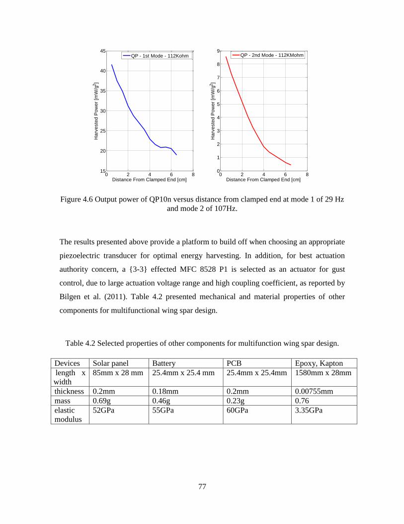
77
Figure 4.6 Output power of QP10n versus distance from clamped end at mode 1 of 29 Hz
and mode 2 of 107Hz.
The results presented above provide a platform to build off when choosing an appropriate
piezoelectric transducer for optimal energy harvesting. In addition, for best actuation
authority concern, a 3-3 effected MFC 8528 P1 is selected as an actuator for gust
control, due to large actuation voltage range and high coupling coefficient, as reported by
Bilgen et al. (2011). Table 4.2 presented mechanical and material properties of other
components for multifunctional wing spar design.
Table 4.2 Selected properties of other components for multifunction wing spar design.
Devices Solar panel Battery PCB Epoxy, Kapton
length x
width
85mm x 28 mm 25.4mm x 25.4 mm 25.4mm x 25.4mm 1580mm x 28mm
thickness 0.2mm 0.18mm 0.2mm 0.00755mm
mass 0.69g 0.46g 0.23g 0.76
elastic
modulus
52GPa 55GPa 60GPa 3.35GPa
0 2 4 6 815
20
25
30
35
40
45
Distance From Clamped End [cm]
Harv
este
d P
ow
er
[mW
/g2]
QP - 1st Mode - 112Kohm
0 2 4 6 80
1
2
3
4
5
6
7
8
9
Distance From Clamped End [cm]
Harv
este
d P
ow
er
[mW
/g2]
QP - 2nd Mode - 112KMohm

78
SIMULTANEOUS ENERGY HARVESTING AND GUST
ALLEVIATION USING REC
This section discusses the possibility of a two mode wind gust control using REC for
small UAVs using the harvested energy from ambient wing vibration based on the
multifunctional composite concept developed in the previous sections. First, an
electromechanical equivalent circuit is described for representing a multifunctional wing
spar. After that, an estimation of harvested power and control power is analyzed.
Equivalent Circuit Representation of a Piezoelectric Generator
The equivalent circuit of piezoelectric generator has been derived by Liang and Liao
(2009) using the single degree freedom mode method. It has also been derived by Elvin
and Elvin (2009b) using the distributed parameter method. This chapter creates an
equivalent circuit in Matlab Simulink using distributed solutions presented by equation
(4.13) and (4.14), and aims to work for multi-mode harvesting. Figure 4.7 shows an
equivalent circuit for the first mode, where the piezoelectric generator is modeled as a
current source. Here, Cps is the piezoelectric capacitance of QP10n. The induced current and
voltage are generated from electromechanical coupled governing equations (4.13) and (4.14).
Figure 4.7 The equivalent circuit for 1st mode piezoelectric generator with resistive
impedance.
A resistance impedance of 112Kohm is implemented to maximize the harvested power
efficiency of the wing spar. The harvested voltage-to-base acceleration FRF for the first
two modes is presented in Figure 4.8 at this optimal load resistance. The assumed modes
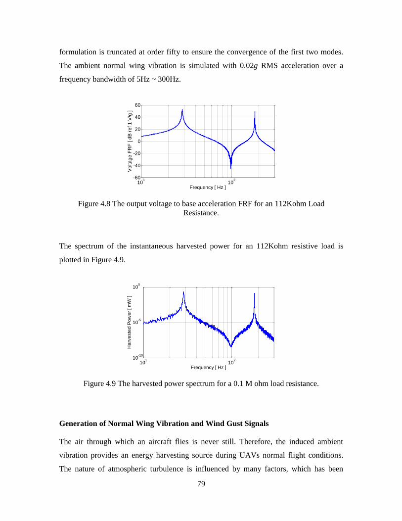
79
formulation is truncated at order fifty to ensure the convergence of the first two modes.
The ambient normal wing vibration is simulated with 0.02g RMS acceleration over a
frequency bandwidth of 5Hz ~ 300Hz.
Figure 4.8 The output voltage to base acceleration FRF for an 112Kohm Load
Resistance.
The spectrum of the instantaneous harvested power for an 112Kohm resistive load is
plotted in Figure 4.9.
Figure 4.9 The harvested power spectrum for a 0.1 M ohm load resistance.
Generation of Normal Wing Vibration and Wind Gust Signals
The air through which an aircraft flies is never still. Therefore, the induced ambient
vibration provides an energy harvesting source during UAVs normal flight conditions.
The nature of atmospheric turbulence is influenced by many factors, which has been
101
102
-60
-40
-20
0
20
40
60
Frequency [ Hz ]
Vo
lta
ge
FR
F [ d
B r
ef 1
V/g
]
101
102
10-10
10-5
100
Frequency [ Hz ]
Ha
rve
ste
d P
ow
er
[ m
W ]

80
studied by Etkin (1972) and many others. The power spectral density (PSD) provides the
designer information of how the mean squared values of the argument is distributed with
frequency ɷ. Two classical representations for the PSD function of atmospheric
turbulence exist: The Von Karman and the Dryden spectrum, see McLean (1969) for
reference. Due to its simple form, the Dryden PSD spectrum in Appendix E is adopted
here for modeling ambience vibration source.
In order to generate the clear sky wing vibration and cumulus cloud gust signals with the
required intensity and scale lengths for a given flight velocity and height, a Gaussian
white noise source n(t) ~ N(0,1) with PSD function of 1, is amplified by a gust gain Kg
and filtered by a wind gust transfer function Gv(s). The schematic representation of the
wind gust generation for open loop and closed loop tip displacement response of the wing
spar is shown in Figure 4.10.
Figure 4.10 Block diagram of wind gust signal generation for open-loop and close-loop
tip displacement responses.
The relationship between the PSD of the output signal vg(t) and the input signal n(t) is
given by:
2 2( ) | ( ) | ( ).
v g v NK G (4.23)
If the power spectrum of the noise source is chosen as a Gaussian White noise, i.e. ΦN (ɷ)
= 1, then the wind gust transfer function becomes:

81
2 2| ( ) | ( ) / .
v v gG K
(4.24)
The solution of equation (4.23) yields:
0
2
0
20
3 3, ( )
( )
.v v
g v
v
v
Us
U LK G s
ULs
L
(4.25)
Here U0 is the aircraft trim velocity, Lv is the vertical scale of turbulence and σv is the
RMS vertical gust velocity. Figure 4.11 shows an example of simulated clear sky wing
vibration (dotted line) and cumulus cloud wind gust (solid line) signals, in acceleration
units g = 9.81 m/s2.
Figure 4.11Ambient wing vibration and wind gust acting on multifunctional wing spar
base, U0=15m/s, Lv =350m.
Gust Alleviation Using REC Control Laws:
Conventional active control laws usually suppress vibration very efficiently, but consume
large amount of external power supply. However, the REC control law developed was
reported to be able to suppress vibration efficiently but reduce the required power
significantly, see Wang and Inman (2011b) for reference. Our previous experimental
results in Wang and Inman (2011a), show a 67% energy reduction when using on-off
switching REC laws for transient vibration control compared to their conventional active
0 0.05 0.1 0.15 0.2 0.25 0.3
-3
-2
-1
0
1
2
3
Time [ s ]
Ba
se
acce
lera
tio
n [ g
]
Cumulus Cloud Wind Gust
Clear Sky Normal Vibration

82
control counterparts. Here, REC laws are implemented for gust alleviation over the
frequency band covering the first two modes, using the energy harvested from ambient
normal wing vibrations. The governing equations of the multifunctional wing spar can be
represented by:
,V V s s a a
Mη Cη Kη f θ θ (4.26)
0.s
p
sVC i
s s sθ η (4.27)
0.a
pVC i
a a a aθ η (4.28)
Here is and i
a denote the current flow through the sensor, and the actuator, respectively.
The circuit representation for gust alleviation using harvested energy is schematically
demonstrated in Figure 4.12. Here, the induced sensing current matrix [B] and sensing
voltage matrix [D] are derived from electromechanical coupled governing equations
(4.26) and (4.27). The induced actuating current matrix [A] and voltage matrix [C] are
derived from electromechanical coupled governing equations (4.26) and (4.28).
Figure 4.12 Schematic representations of gust alleviation using harvested energy.
Upon encountering the cumulus cloud disturbance shown in Figure 4.11, the REC law
yield 28 dB reduction of its 1st mode (29Hz) and 37dB reduction of its 2
nd mode (107Hz),
as seen in Figure 4.13. Here the logarithm relative tip displacement (dB reference 1
meter) is shown in linear coordinate.

83
Figure 4.13The disturbed tip displacement spectrum of multifunctional wing spar before
and after REC control.
In time domain, the wing spar tip displacement RMS value is reduced from 1.6 mm (open
loop in solid line) down to 0.35 mm (closed loop in dot line). The maximum tip
displacement is reduced from ±4.5 mm down to ±1.0 mm, as seen in Figure 4.14.
Figure 4.14Winds disturbed multifunctional wing spar tip response in time domain before
and after REC control.
Power Flow for Simultaneous Energy Harvesting and Gust Alleviation
The REC laws produce a nonlinear switching logic by saturating the actuating voltage
provided by the positive strain feedback (PSF) controller. The PSF control algorithm
101
102
-140
-120
-100
-80
-60
Frequency (Hz)
Re
lative
Tip
Dis
pla
ce
me
nt (d
B r
ef 1
m)
Open Loop - FRF
Reduced Energy Control - FRF
1.5 2 2.5 3
-6
-4
-2
0
2
4
6
Time [ s ]
Re
lative
Tip
Dis
pla
ce
me
nt [ m
m ]
Open Loop
Reduced Energy Control

84
takes the similar transfer function form as the positive position feedback control law, see
Wang and Inman (2011d) for reference. However, the feedback signals act from the PZT
strain sensor instead of a position sensor. This collocate function removes external
sensing sources and/or external power supply. As seen from Figure 4.15, the Laplace
transfer function of PSF for the 1st mode, driven by a PSF op-amp and a voltage buffer
op-amp, is of the following form:
2
22.
2
f
f
o
i f f
kv
v s s
(4.29)
Here the PSF filter parameters: gain k, damping ratio ζf , filter natural frequency ɷf are
achieved by:
1 2 3
1 2 2 3
252
1 4
1, ,
( ).
2(1 )
f
f f
C R R
C C R R
RR
R Rk
(4.30)
Here, C1 and C2 are capacitance components, R1, R2, R3, R4 and R5 are resistive
components.
Figure 4.15 Block Diagram of the 1st Mode PSF Control.

85
In Figure 4.15, the voltage buffer op-amp is interposed to reduce actuation current flow.
Two parallel PSF controllers are designed for gust alleviation for two specific modes.
The PSF feedback signals are periodically saturated to satisfy the REC switching logic
(not discussed here but demonstrated in Chapter 3. The instantaneous power associated
with the actuator is defined as the product of actuation voltage and actuation current:
( ) ( ) .( )ins a aP t v t i t (4.31)
Note that the piezoelectric actuation voltage associates with the REC laws, and the
actuation current depends on the electrical impedance of the control circuits. The real part
and the imaginary part of the cross-spectrum between instantaneous voltage and current
represent the active (real) power and reactive power associated with a given component,
respectively. The active power (thick line) and reactive power (thin line) associated with
each PSF and Buffer op-amp of the 1st mode and the 2
nd mode is presented in Figure
4.16. The unit of active and reactive power is watt (w) and volt-ampere reactive (var),
respectively. It shows that the 1st mode control Op-amps require 90 times more active
power than that of the 2nd
mode.
Figure 4.16 Active and reactive power spectrum of 1st Mode and 2
nd Mode PSF and
buffer Op-amps.
The active power (thick line) and reactive power (thin line) associated with the summing
Op-amp, and the MFC 8528P1 actuator is shown in Figure 4.17. The active and reactive
10 20 30 40
0
0.18
Active [ m
W ]
Frequency [ Hz ]
a. 1st Mode PSF Op-amp
10 20 30 400.08
0
Reactive [ m
VA
r ]Active
Reactive
10 20 30 40
0
1.1
Active [ m
W ]
Frequency [ Hz ]
b. 1st Mode Buffer Op-amp
10 20 30 400.2
0
Reactive [ m
VA
r ]Active
Reactive
170 175 180 185 190
0
3e-3
Active [ m
W ]
Frequency [ Hz ]
c. 2nd Mode PSF Op-amp
170 175 180 185 1902e-3
0
Reactive [ m
VA
r ]Active
Reactive
170 175 180 185 190
0
11e-3
Active [ m
W ]
Frequency [ Hz ]
d. 2nd Mode Buffer Op-amp
170 175 180 185 190
1e-30
Reactive[ m
VA
r ]
Active
Reactive

86
power associated with each PSF and buffer op-amp and each transducer are detailed in
Table 4.3.
Figure 4.17Active and reactive power associated with the summing Op-amp and the
MFC 8528 P1actuator.
Table 4.3Power Associated With Each Electric Component.
Electric Element Active Power
(mW)
Reactive Power
(mVAr)
Apparent Power
(mVA)
Power
Factor
1st PSF Op-Amp 0.15 0.09 0.18 0.83
1st Buffer Op-Amp 3.46 0.00 3.46 1
2nd
PSF Op-Amp 0.10 0.03 0.10 1
2nd
Buffer Op-Amp 0.30 0.00 0.30 1
Summing Op-Amp 3.65 4.94 6.78 0.54
Actuator 6.42 4.94 8.63 0.74
Harvester 0.16 0.00 0.16 1
Known from Table 4.3, the active power required for 28dB reduction of the 1st mode, and
37dB reduction of the 2nd
mode in tip displacement is 6.42mW, which is 40 times higher
than the harvesting power of 0.16mW. That is, in order to control a 1 second time span
cumulus wind gust, 40 seconds of harvesting are needed. Note that practical loads deliver
both active and reactive power and also waste energy into heat. Therefore, the apparent
power, which is the product of the RMS of voltage and current, is also calculated and
presented in Table 4.3, with the unit of Volt-Ampere (VA). The power factor here is
defined as the active power divided by apparent power.
10 20 30 40
0
1
Active [ m
W ]
Frequency [ Hz ]
a. Summing Op-amp
170 175 180 185 190
0
0.35
Active [ m
W ]
Frequency [ Hz ]
10 20 30 40
0
Active [ m
W ]
Frequency [ Hz ]
b. Actuation Power
170 175 180 185 190
0
0.35
Active [ m
W ]
Frequency [ Hz ]
10 20 30 402
0
Reactive [ m
VA
r ]
Active
Reactive
170 175 180 185 1900.2
0
Reactive [ m
VA
r ]
Active
Reactive
10 20 30 402
0
Reactive[ m
VA
r ]
Active
Reactive
170 175 180 185 1900.2
0
Reactive[ m
VA
r ]
Active
Reactive

87
CHAPTER SUMMARY
A novel concept of simultaneous energy harvesting and gust alleviation is presented in
this chapter. The motivating application is a multifunctional wing spar of a UAV with the
goal of providing self-contained gust alleviation. A wing spar is designed to be
compatible with collocated self-harvesting, self-sensing and self-controlling
functionalities using piezoelectric materials. The basic design factors are discussed for a
beam-like multifunctional wing spar with load-bearing energy harvesting, strain sensing
and self-controlling functions. The configurations, locations and operating modes of
piezoelectric transducers are also discussed for optimal power generation. The reduced
energy control law is implemented to reduce control power while preserving control
performance. Theoretical modeling and numerical simulations show that the tip
displacement due to a wind gust disturbance can be reduced by 28dB and 37dB for the 1st
and the 2nd
mode, respectively, using energy harvested from ambient wing vibrations. A
flexible solar panel is also modeled but not used in the analysis. Future work will focus
on solar energy harvesting in order to reduce the recharging time substantially. Another
consideration for future work is finite element modeling for optimized multifunctional
structures.

88
CHAPTER 5 EXPERIMENTAL VALIDATION OF AN
AUTONOMOUS GUST ALLEVIATION SYSTEM
This chapter details experimental characterization and validation of an autonomous gust
alleviation system building upon recent advances in harvester, sensor and actuator
technology that have resulted in thin, ultra-light weight multilayered composite wing
spars. This multifunctional spar is considered an autonomous gust alleviation system for
small UAVs powered by the harvested energy from ambient vibration during their normal
flight conditions. Experimental characterization and validation are performed on
cantilever wing spars with micro-fiber composite transducers controlled by reduced
energy controllers. Normal flight vibration and wind gust signal is simulated using
Simulink and Control desk and then generated for experimental validation analysis for
gust alleviation. Considering the aluminum multifunctional wing spar, a reduction of
11dB and 7dB is obtained respectively for the first and the second mode. Considering the
fiberglass composite multifunctional wing spar, a reduction of 16dB is obtained for the
first vibration mode. Power evaluations associated with various electronic components
are also presented for both cases. Energy harvesting abilities of monolithic and micro
fiber composite transducers are also compared for the fiberglass composite wing spar.
This work demonstrates the use of reduced energy control laws for solving gust
alleviation problems in small UAVs, provides the experimental verification details, and
focuses on applications to autonomous light-weight aerospace systems.
NOMENCLATURE
ζ1 = first mode damping ratio of the controller
ζ2 = second mode damping ratio of the controller
g1 = first mode control gain of the controller
g2 = second mode control gain of the controller
Etot = total required control energy
Etr = transient energy
Pst = required power for steady state vibration control
ts = setting time
tg = wind gust duration

89
INTRODUCTION
The increasing demand for ultra-light weight materials in small UAVs results in
extremely flexible structures with low-frequency vibration modes. Suppression of
undesired vibrations in such flexible structures with limited energy is becoming an
important design problem to develop energy-autonomous controllers powered using the
harvested ambient energy. Reduced energy control laws developed in Chapter 3 address
the trend towards autonomous aerospace structures with limited energy supply. Small
UAVs are usually comprised of large ultra-light weight structures with multilayered
composite components. The multifunctional wing spar designed in Chapter 4, is one
typical example. Within these composite structures, the individual components
themselves may have complex characteristics, for example a micro-fiber composite
(MFC) actuator in the context of gust alleviation. This chapter is dedicated to
experimental characterizations building upon recent advances in harvester, sensor and
actuator technology that have resulted in thin, ultra-light weight multi-layered composite
wing spars. The multifunctional wing spar of small UAVs is considered an autonomous
gust alleviation system powered by harvested energy from ambient vibration during their
normal flight conditions.
Experiments are performed on cantilever wing spars with MFC transducers controlled by
reduced energy controllers. Considering the first two vibration modes, the control energy
requirements are compared and evaluated. This work demonstrates the use of reduced
energy control laws for solving gust alleviation problems in small UAVs, provides the
experimental setup and verification details, and focuses on applications to autonomous
aerospace systems. These successful experiments validate the autonomous gust
alleviation systems on multifunctional wing spars with both aluminum and honeycomb
core fiberglass substrates. The experimental validation will be carried out through the
analysis of these two examples.

90
This chapter is organized as follows. In Section 2, experimental validation of reduced
energy control law is given for a piezoelectric layer bonded aluminum wing spar.
Experimental characterization of this control law under study is fully described. The
experimental results concerning the power flow associated with various electric elements
are also presented. Another experiment given in Section 3 is dedicated for the
autonomous gust alleviation system building on a honeycomb core fiberglass composite
sandwich wing spar, as presented in section 3. The first step characterizes and compares
energy harvesting abilities of monolithic and micro fiber composite transducers. The next
step addresses numerical predictions of Chapter 4, along with experimental data. Closing
remarks and future perspectives are briefly outlined in Section 4.
EXPERIMENTAL VALIDATION OF REDUCED ENERGY
CONTROL ON A PIEZOELECTRIC LAYER BONDED
ALUMINUM WING SPAR
This step of work is dedicated to experimental validation of the feasibility of reduced
energy control for autonomous gust alleviation system. In this part of study, an
autonomous gust alleviation system builds on a piezoelectric layered bonded aluminum
wing spar. This autonomous multifunctional wing spar is designed to evaluate control
performance of reduced energy control (REC) compared to positive strain feedback
control (PSF) developed in Chapter 4.
Experimental Setup for Validation of Reduced Energy Control Law
As stated before, this experimental study is conducted in order to evaluate control
performance of REC compared to PSF with a focus on the first two transverse vibration
modes. The experimental specimen is a flexible cantilevered multifunction wing spar. Its
photographic and schematic representation is given in Figure 5.1 (a) and (b). Both PZT
layers are positioned 54mm away from the root end of the beam, corresponding to the
beam length attached to the fuselage when the wing spar is fully inserted into the wing.
Therefore, both piezoelectric devices are placed at the root of the cantilever wings. The
MFC actuator is controlled by REC and PSF controllers, respectively, for control
performance comparison. The geometry and material properties of this multifunctional

91
wing spar are listed in Table 5.1. In the first step of this experiment, both controllers
build in Matlab Simulink using Control Desk software and a dSPACE real time control
board. Whichever controller that has the best performance is built and tested in a Printed
Circuit Board (PCB) for further experimental study.
(a)
(b)
Figure 5.1 (a) A photographic (b) A schematic representation of front view and back
view of the aluminum baseline multifunctional wing spar.
Table 5.1 Geometry and Material Properties for the Aluminum Baseline Multifunctional
Wing Spar.
Property/Component QP10n MFC8528P1 Aluminum Substrate
Overall Length 50.8mm 112mm 504mm
Overall Width 25.4mm 40mm 28mm
Overall Thickness 0.508mm 0.18mm 3.05mm
Overall Mass 2.835 gram 4.06gram 139.4gram
The overall experimental setup is shown in Figure 5.2, where the representative
multifunctional wing spar is clamped to an APS Dynamics ELECTRO-SEIS long stroke
shaker with frequency range 0.1 Hz ~ 200 Hz. The shaker is driven by an APS DUAL-
MFC8528-P1
QP10N
Shaker
Accelerometer
Charge Amplifier
x
z
B. QP16N (Harvester, Sensor)A. Aluminum Substrate
C. MFC(Actuator)
L1=54mm L2=113.6mm L4=504mm
D. Epoxy DP 460, Kapton
L3=400mm

92
MODE power amplifier. Considering the same nature of wing vibration signals (for
harvesting purpose) and wind gust signals (for control purpose), the Gaussian white noise
and Dryden PSD function in Appendix E are implemented in Simulink to produce input
signals in both cases. A 10 M ohms optimal resistive load is employed to provide
allowable operation voltage (5V for data acquisition system).
Figure 5.2 Gust alleviation experimental setup using REC Laws.
Experimental Results
The absolute tip displacement is measured using an MTI LTC-50-20 laser sensor. The
frequency spectrum of the measured relative tip displacement is calculated in order to
compare control performance for a range of control parameters. The investigated control
gains and corresponding vibration reduction levels are shown in Figure 5.3 and listed in
Table 5.2.
1. Multifunctional Wing Spar
2. Circuit Board3. PCw/Simulink4. dSPACE Board5. Low Pass Filter6. Displacement
Laser Sensor
7. Power Amplifier8. Siglab
1
8
4
65
2
3
7

93
Figure 5.3 Control performance of the PSF controllers for different control gains
(damping ratio of mode 1: ζ1= 0.15 and mode 2: ζ2 = 0.35).
Table 5.2 Control Performance versus PSF Control Gain.
1st Mode Control Gain 0.8 0.6 0.4
2nd
Mode Control Gain 0.8 0.6 0.4
1st Mode Reduction 13dB 11dB 9dB
2nd
Mode Reduction 8dB 7dB 6dB
In addition to above results, the experimental measurement also shows that when the
control gain is fixed (0.1 < g1, g2 < 1.2), changing the controller’s damping ratio (0.10 <
ζ1< 0.55, 0.30 < ζ2< 0.75) does not affect the control performance. Figure 5.4 shows that
the same control performance (11dB reduction for the 1st mode, 7dB reduction for the 2
nd
mode from open circuit control (dashed line)) is reached using the PSF controller (solid
line) with gains g1 = 0.6, g2 =0.6, damping ratios ζ1 = 0.15, ζ2 = 0.35; and using the
REC controller (dot line) with gains g1 = 0.8, g2 = 0.8, damping ratios ζ1 =0.15, ζ2 =
0.35, saturation voltage of 110 Volt. Again, this plots the relative tip displacement read
from laser sensor, not the tip-displacement-to-base-acceleration FRF but has the same
trend.
9 10 11 12 13 14-105
-100
-95
-90
-85
-80
Frequency [ Hz ]
Rela
tive T
ip D
ispla
cem
ent [ dB
ref 1m
]
Open-Circuit
g1 = 0.8 / g2 = 0.8
g1 = 0.6 / g2 = 0.6
g1 = 0.4 / g2 = 0.4
70 72 74 76-140
-135
-130
-125
-120
-115
Frequency [ Hz ]
Rela
tive T
ip D
ispla
cem
ent [ dB
ref 1m
]
Open-Circuit
g1 = 0.8 / g2 = 0.8
g1 = 0.6 / g2 = 0.6
g1 = 0.4 / g2 = 0.4

94
Figure 5.4 Vibration control performance using the PSF and REC Laws.
The time domain steady state responses of PSF and REC are shown in Figure 5.5. Both
the PSF controller (solid line) and the REC controller (dashed line) are designed to
reduce the RMS value of the relative tip displacement from 3.0 mm for the open circuit
case (dotted line) down to 1.2 mm for closed loop control. The two-mode PSF controller
has gains g1 = 0.6 (1st mode), g2 =0.6 (2
nd mode) and damping ratios ζ1= 0.15 (1
st mode),
ζ2 = 0.35 (2nd
mode). The two-mode REC has gains g1 = 0.8(1st mode), g2 = 0.8(2
nd
mode), and damping ratios ζ1 =0.15(1st mode), ζ2 = 0.35(2
nd mode), with saturation
voltage of 110 Volt.
9 10 11 12 13 14-105
-100
-95
-90
-85
-80
-75
Frequency [ Hz ]
Rela
tive T
ip D
ispla
cem
ent [ dB
ref 1m
]
70 72 74 76-140
-135
-130
-125
-120
-115
-110
Frequency [ Hz ]
Rela
tive T
ip D
ispla
cem
ent [ dB
ref 1m
]
Open-Circuit
PSF Control
Reduced Energy Control
Open-Circuit
PSF Control
Reduced Energy Control

95
Figure 5.5 Control performance using PSF and REC laws (time history of relative tip
displacement response).
The actuation voltage is amplified 200 times by a TREK 2220 power amplifier, and then
fed into the MFC actuator. Figure 5.6 presents the actuation voltage required by the PSF
(solid line) and the reduced energy (dotted line) control laws, satisfying identical control
performance.
Figure 5.6 Actuation voltage measurements required by the PSF and REC laws.
2.8 2.9 3 3.1 3.2 3.3 3.4 3.5 3.6 3.7 3.8-6
-4
-2
0
2
4
6
Time [ s ]
Rela
tive T
ip D
ispla
cem
ent [ m
m ]
Open-Circuit
PSF Control
Reduced Energy Control
0.8 0.9 1 1.1 1.2 1.3 1.4 1.5 1.6 1.7 1.8-300
-200
-100
0
100
200
300
Time [ s ]
Actu
ation V
oltage [
V ]
PSF Control g0.6
Reduced Energy Control v120

96
The TREK 2220 power amplifier also has a current monitor function available for
measuring actuation current. Figure 5.7 shows the actuation current required by the PSF
(Solid line) and the reduced energy (dotted line) control laws.
Figure 5.7 Actuation current measurements required by the PSF and REC laws.
The instantaneous power required by the PSF Controller (solid line) and the REC
Controller (dotted line) is shown in Figure 5.8.
Figure 5.8 Instantaneous power required by PSF and REC laws.
0.8 0.9 1 1.1 1.2 1.3 1.4 1.5 1.6 1.7 1.8
-0.15
-0.1
-0.05
0
0.05
0.1
0.15
Time [ s ]
Actu
ation C
urr
ent
[ m
A ]
PSF Control g0.6
Reduced Energy Control v120
0.5 0.6 0.7 0.8 0.9 1 1.1 1.2 1.3 1.4 1.5-10
-5
0
5
10
15
20
Time [ t ]
Insta
nta
neous P
ow
er
[ m
W ]
PSF Control Law
Reduced Engergy Control Law

97
Figure 5.9 compares the active and reactive power from experimental measurements in
the frequency domain. The data is recorded for duration of 60s.
Figure 5.9 Active and reactive power required by PSF and REC laws.
The average harvested power Phav
of the aluminum based multifunctional wing spar is
found to be 0.3 mW. The other power and energy elements associated with the PSF and
REC Laws are detailed in Table 5.3. All values are given to satisfy 11dB reduction of the
1st mode and 7dB reduction of the 2
nd mode, compared to open-circuit. Here Etr is the
energy consumed for transient vibration control and Pst is the power required for steady
state vibration control. The settling time ts is defined as the time needed for the controlled
response to reach 40 % of the amplitude of the open loop response, and is found to be 0.8
s in the present case.
Table 5.3 Power and Energy Elements Associated with PSF and REC Laws.
Element PSF REC Ratio of Reduction
Voltage RMS (V) 100 82.3 18 %
Current RMS (mA) 0.065 0.053 18 %
Required Energy Etr (mJ) 6.6 1.6 76 %
Average Power Pst (mW) 1.2 1.0 17 %
9 10 11 12 13 14
0
2
Active [ m
W ]
Frequency [ Hz ]
a. PSF Control Law
70 72 74 76
0
0.05
Active [m
W]
Frequency [ Hz ]
9 10 11 12 13 14
0
2
Active [m
W]
Frequency [ Hz ]
b. Reduced Energy Control Law
70 72 74 76
0
0.05
Active [m
W]
Frequency [ Hz ]
9 10 11 12 13 143
0
Reactive [ m
VA
r ]
Active
Reactive
70 72 74 760.05
0
Reactive [m
VA
r]
Active
Reactive
9 10 11 12 13 143
0R
eactive [m
VA
r]
Active
Reactive
70 72 74 760.05
0
Reactive [m
VA
r]
Active
Reactive

98
For any wind gust duration tg > ts, the total required control energy Etot can be calculated
by:
*( ).tot tr st g sE E P t t (5.1)
For PSF and REC control systems, the total required energy formula becomes:
6.6 1.2*( 0.8).
1.6 1.0*( 0.8).
PSF
tot g
REC
totg
E t
E t
(5.2)
The harvesting time th required to control a wind gust of duration tg is given by:
.tot
h harv
Et
P (5.3)
EXPERIMENTAL CHARACTERIZATION AND VALIDATION
OF AN AUTONOMOUS GUST ALLEVIATION SYSTEM ON A
HONEYCOMB CORE FIBERGLASS COMPOSITE SANDWICH
WING SPAR
The increasing trend of lighter and stronger aerospace structures can be easily achieved
by the use of composite materials. Sandwich composites are one of popular examples
which have been tailored for many specific applications, whose major advantage is their
high flexural stiffness to weigh ratio. Fiber reinforced composites with a low-density core
find increasing use in aerospace structures. A honeycomb core fiberglass composite
sandwich panel manufactured by ACP composites (ACP) is cut into a beam substrate to
build an autonomous gust alleviation wing spar for small UAVs. This honeycomb core
fiberglass beam substrate is sandwiched between two layers of uni-directional fiberglass
pre-preg and an epoxy film adhesive. The fiberglass plies are layered up at 0º and 90º to
produce high strength-to-weight and rigidity-to-weight ratios. The final experimental test
builds on recent advances on monolithic and micro fiber composite transducers, sandwich
composites, and printed circuit boards. The focus is experimental characterization and
validation of the autonomous gust alleviation system. Figure 5.10 illustrates an
experimental setup and schematic representation of the autonomous gust alleviation
system.

99
(a) (b)
Figure 5.10 (a) A photographic representation (b) a schematic representation of the
autonomous gust alleviation system building on a honeycomb core fiberglass
multifunctional wing spar.
Experimental Setup for Harvesting Ability Characterizations of Monolithic QP10n
and Micro Fiber Composite MFC 85281P1
The motivation of this step is to characterize harvesting abilities, and material properties
of two types of piezoelectric transducers. The considered vibration based cantilever
harvesters builds on two honeycomb core fiberglass composite sandwich wing spars, with
length 593.7mm, width 38mm and thickness 3.175mm. The hanging over length of the
substrate is 34.5mm. This results the effective length of 559.2 mm. The length to
thickness ratio of this design satisfies the required span wise rigidity for use in the small
UAVs. One of these rectangular wing spars is bonded by a monolithic piezoelectric layer
QP10n from QuickPack, as shown in Figure 5.11 (a). The other one is bonded by a micro
fiber composite piezoelectric layer MFC8528P1 from Smart Material Corp, as shown in
Figure 5.11 (b). The geometry and material properties of each piezoelectric transducer
are listed in Table 5.4.
(a) (b)
Figure 5.11 A prototype of (a) the MFC 8528P1 (b) the QP10n.
AccelerometerQP10N Shaker MFC 8528P1
PCB
x
z
A. QP16N (Harvester, Sensor)D. Printable Circuit Board (PCB)
B. Honeycomb Core Fiberglass
C. MFC(Actuator)
L1=25 mm L2=84.6 mm
L3=110 mm
L4=552 mm
E. Epoxy DP 460, Kapton
L4=592 mm

100
Table 5.4 Geometry and Material Properties for Two Unimorph Piezoelectric Harvesters.
Property/Component QP10n MFC8528P1 Composite Substrate
Overall Length 50.8mm 112mm 593.7mm
Overall Width 25.4mm 40mm 38mm
Overall Thickness 0.508mm 0.18mm 3.175mm
Overall Mass 2.835 gram 4.06gram 13.97gram
Both piezoelectric device layers are bonded with Kapton layer and 460 3D epoxy layers
under 0.8 atm vacuum for 6 hours to minimize variations in epoxy thickness and
eliminate air gaps. The processing procedure is 1) clean composite sandwich substrate
and the respective piezoelectric layer from Figure 5.10(a) and (b) using IPA and wipers;
2) prepare the vacuum bag, silk and cotton; 3) tape the silk layer on the bottom side of the
composite sandwich substrate; 4) clean the glue gun, as shown in Figure 5.12 (a); 5) mix
some 3D ScotchWeldTM
DP460 two part epoxy in a small try with the spatula; 6) spread a
thin layer of the mixed epoxy all over the respective device; 7) remove the surplus by
scrapping lines with the spatula; 8) glue together the respective device layer with the
composite sandwich substrate; 9) tape them together; 10) tape the silk layer over the
respective device layer; 11) put the bonded beam in the cotton layer and insert it in the
vacuum bag; 12) tape the vacuum bag tightly; 13) plug the vacuum pump 0523-101 from
Gast Manufacturing Inc, and vacuuming at 20kPa for about 6 hours, as shown in Figure
5.12 (b) and (c); 14) clean everything. After curing, turn off vacuum pump, take off silk
layer and tapes, and remove any excess epoxy from the edges of the device.
(a) (b) (c)
Figure 5.12 A photographic representation of (a) the DP460 glue gun (b) the vacuum
process (c) the pressure meter panel.

101
It is known that maximum power output occurs near the resonant frequency of each
unimorph cantilever harvester. Therefore, the first step focuses on output power
characterization of each harvester connected with a set of resistive load, (as shown in
resistive shunt in Figure 2.5(a)). Table 5.5 lists the nominal resistors used in the
experiment and their effective values due to the manufacturing error and the impedance
of the data acquisition system.
Table 5.5 Nominal Resistors and their Effective Values.
Nominal Resistor (Ω) Effective Load Resistance (Ω)
1k 1.8k
3k 3.3k
5k 4.9k
10k 9.9k
20k 21.7k
30k 32.5k
40k 40.6k
50k 50.3k
60k 62k
70k 71.3k
80k 81k
90k 92.8k
100k 98.8k
112k 112k
139k 139k
200k 199k
250k 250k
300k 300k
370k 377k
494k 494k
609k 609k
697k 697k
830k 839k
970k 977k
2M 1.985M
3M 2.724M
4M 3.76M
5M 4.770M
7M 7.01M
10M 9.44M
20M 22M

102
The purpose of this chapter is to study ambient vibration transduction caused by clear sky
atmospheric turbulence, therefore, the Dryden’s PSD spectrum function (Appendix E) is
used to represent atmospheric turbulence. Equations (4.23) to (4.25) are employed to
address ambient vibration, which is used to excite cantilever wing spar using the
dSPACE 1005 real time control board, Matlab Simulink and Control Desk software. In
consistent with Chapter 4, the small UVA trim velocity is 15m/s, and the vertical scale of
turbulence is 350m. The excitation acceleration is measured by a PCB Piezotronics
Model U352C67 shear accelerometer with sensitivity of 0.99 V/g and bandwidth from
0.5Hz to 10 kHz. A PCB charge amplifier 482A16 is implemented with a 10x gain. The
output voltage recorded using dSPACE 1005 and Control Desk software. The
photographic experimental setup is given in Figure 5.13.
(a) (b)
Figure 5.13 (a) Energy harvesting experimental setup for QP10n piezoelectric harvester
(b) dSPACE data acquisition system.
The objective is to compare the experimental measurement of voltage, current and power
output with analytical modeling and numerical simulation of Chapter 4. The focus is
placed on the first two resonant modes at 10.6Hz and 57.4Hz respectively. In order to
obtain better agreements of numerical simulation with experimental data, a tuning
procedure is required based on analytical solutions derived in Chapter 4. First, the modal
mechanical damping is experimentally identified with high accuracy. This is very
important, since it affects peak power amplitude significantly near resonance frequencies.
The mechanical damping ratio is identified graphically using the quadrature peak picking
on the open-loop FRF plot. In all these case studies, the mechanical damping ratio is kept
QP10n
Printed Circuit Board
Clamp
Shaker

103
at ζ1 = 0.009 for the first mode, and ζ2 = 0.0069 for the second mode. In addition, the
accurate distance from the clamped length to the harvester, the accurate stiffness, internal
capacitance and coupling coefficient of QP10n and MFC are also very important in order
to receive good agreements as shown from Figure 5.14-5.17 and Figure 5.19-5.22.
Details will be presented later with respect to each relevant plot.
Experimental Characterizations of Harvesting Abilities for Monolithic QP10n
Transducer
The experimental and numerical comparison of voltage-per-acceleration for the QP10n
harvester is plotted in Figure 5.14 along with a set of effective load resistance for both
resonant modes. The numerical curves agree very well with the experimental data points
for both cases. The peak voltage amplitude of both modes, as expected from the
theoretical modeling and simulation of Chapter 4, increases monotonically with
increasing load resistance. The peak voltage amplitude of both modes increases by two
orders of magnitude as the load resistance is increased from 1.8 kΩ to 22MΩ.
Figure 5.14 Experimental and numerical simulation comparison of the first two mode
voltage-per-acceleration with a set of effective load resistance excited by clear sky
atmospheric turbulence for the QP10n piezoelectric harvester.
The experimental and numerical comparison of current-per-acceleration for the QP10n
harvester is plotted in Figure 5.15 along with a set of effective load resistance with
respect to the first two resonant modes. The simulation curves exhibit near perfect
agreements with the experimental data points for both modes.
103
104
105
106
107
100
101
102
103
Load Resistance (Ohm)
Ha
rve
ste
d V
olta
ge
(V
/g)
QP10N - 1st Mode - Simulation
QP10N - 1st Mode - Experimental
QP10N - 2nd Mode - Simulation
QP10N - 2nd Mode - Experimental

104
Figure 5.15 Experimental and numerical simulation comparison of the first two mode
current-per-acceleration with a set of effective load resistance excited by clear sky
atmospheric turbulence for the QP10n piezoelectric harvester.
The experimental and numerical comparison of power-per-acceleration for the QP10n
harvester is shown in Figure 5.16 along with a set of effective load resistance, with
respect to the first two resonant modes. Both simulation curves agree very well with the
experimental data points. It is observed from Figure 5.16 that, the first mode peak power
amplitude of 28.2mW/g2 is obtained for the optimum load resistance of 112kΩ, and the
second mode peak power amplitude of 9.8mW/g2 for the optimum load resistance of
20.2kΩ.
Figure 5.16 Experimental and numerical simulation comparison of the first two mode
power-per-acceleration with a set of effective load resistance excited by clear sky
atmospheric turbulence for the QP10n piezoelectric harvester.
103
104
105
106
107
10-3
10-2
10-1
100
101
Load Resistance (Ohm)
Ha
rve
ste
d C
urr
en
t (m
A/g
)
QP10N - 1st Mode - Simulation
QP10N - 1st Mode - Experimental
QP10N - 2nd Mode - Simulation
QP10N - 2nd Mode - Experimental
103
104
105
106
107
10-1
100
101
102
Load Resistance (Ohm)
Ha
rve
ste
d P
ow
er
(mW
/g2)
QP10N - 1st Mode - Simulation
QP10N - 1st Mode - Experimental
QP10N - 2nd Mode - Simulation
QP10N - 2nd Mode - Experimental

105
Figure 5.17 shows numerical simulation of voltage-to-base-acceleration FRFs at optimal
load resistance of 112kΩ, along with experimental data. A few tuning procedures have
been performed to predict the dynamic response with very good accuracy. First, the
effective distance from the clamped root to the harvester is slightly tuned in order to
better match the peak amplitude ratio of the first mode and the second mode. Then, the
mass and stiffness of the substrate and harvester is tuned slightly to better match the
resonant frequency ratio of the first mode and the second mode. The slight tuning of the
composite substrate stiffness helps adjusting the resonant frequency of each mode, but
has no effect on the ratio of the frequencies. In the end, the internal capacitance of the
harvester is adjusted in order to better match the shape of the FRF curve. In addition, the
coupling coefficient term of the harvester is very easy to be identified, since it determines
the overall amplitude of the frequency response. All the characterized material properties
are presented in Table 5.5.
Figure 5.17 Experimental and numerical simulation comparison of the voltage-to-base-
acceleration FRF at optimum load resistance excited by clear sky atmospheric turbulence
for the QP10n piezoelectric harvester.
In order to clearly see the change of peak-wise behavior resulted from variation of load
resistance, Figure 5.18 displays the output voltage-to-base-excitation FRFs for all these
resistive loads from Table 5.4. The trend exhibits consistency with derived analytical
models of Chapter 4.
0 10 20 30 40 50 60 7010
-2
10-1
100
101
102
103
Frequency (Hz)
Vo
lta
ge
to
Ba
se
Acce
lera
tio
n F
RF
(V
/g)
QP10N - Simulation - 139kohm
QP10N - Experimental - 139kohm
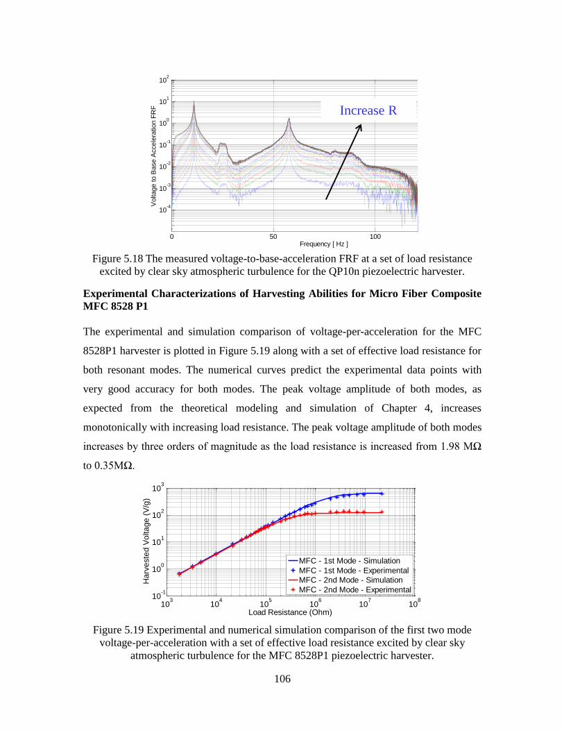
106
Figure 5.18 The measured voltage-to-base-acceleration FRF at a set of load resistance
excited by clear sky atmospheric turbulence for the QP10n piezoelectric harvester.
Experimental Characterizations of Harvesting Abilities for Micro Fiber Composite
MFC 8528 P1
The experimental and simulation comparison of voltage-per-acceleration for the MFC
8528P1 harvester is plotted in Figure 5.19 along with a set of effective load resistance for
both resonant modes. The numerical curves predict the experimental data points with
very good accuracy for both modes. The peak voltage amplitude of both modes, as
expected from the theoretical modeling and simulation of Chapter 4, increases
monotonically with increasing load resistance. The peak voltage amplitude of both modes
increases by three orders of magnitude as the load resistance is increased from 1.98 MΩ
to 0.35MΩ.
Figure 5.19 Experimental and numerical simulation comparison of the first two mode
voltage-per-acceleration with a set of effective load resistance excited by clear sky
atmospheric turbulence for the MFC 8528P1 piezoelectric harvester.
0 50 100 150
10-4
10-3
10-2
10-1
100
101
102
Frequency [ Hz ]
Voltage to B
ase A
ccele
ration F
RF Increase R
103
104
105
106
107
108
10-1
100
101
102
103
Load Resistance (Ohm)
Ha
rve
ste
d V
olta
ge
(V
/g)
MFC - 1st Mode - Simulation
MFC - 1st Mode - Experimental
MFC - 2nd Mode - Simulation
MFC - 2nd Mode - Experimental

107
The experimental and numerical comparison of current-per-acceleration for the MFC
8528P1 harvester is plotted in Figure 5.20 along with a set of effective load resistance
with respect to the first two resonant modes. Both simulation curves exhibit very good
agreements with the experimental data points for both cases.
Figure 5.20 Experimental and numerical simulation comparison of the first two mode
current-per-acceleration with a set of effective load resistance excited by clear sky
atmospheric turbulence for the MFC 8528P1 piezoelectric harvester.
The power-per-acceleration for the MFC 8528P1 harvester is shown in Figure 5.21 along
with a set of effective load resistance, with respect to the first two resonant modes. The
simulation curves agree very well with the experimental data points. It is observed from
Figure 5.21 that, the first mode peak power amplitude of 50.8mW/g2 is obtained for the
optimum load resistance of 1.98 MΩ, and the second mode peak power amplitude of
9.8mW/g2 for the optimum load resistance of 0.35 MΩ.
Figure 5.21 Experimental and numerical simulation comparison of the first two mode
power-per-acceleration with a set of effective load resistance excited by clear sky
atmospheric turbulence for the MFC 8528P1 piezoelectric harvester.
103
104
105
106
107
108
10-3
10-2
10-1
100
Load Resistance (Ohm)
Ha
rve
ste
d C
urr
en
t (m
A/g
)
MFC - 1st Mode - Simulation
MFC - 1st Mode - Experimental
MFC - 2nd Mode - Simulation
MFC - 2nd Mode - Experimental
103
104
105
106
107
108
10-2
10-1
100
101
102
Load Resistance (Ohm)
Ha
rve
ste
d P
ow
er
(mW
/g2)
MFC - 1st Mode - Simulation
MFC - 1st Mode - Experimental
MFC - 2nd Mode - Simulation
MFC - 2nd Mode - Experimental

108
Figure 5.22 displays numerical simulation of voltage-to-base-acceleration FRFs at
optimal load resistance of 1.98MΩ, along with experimental data. It can be observed that
numerical simulation agrees with experimental plots very well.
Figure 5.22 Experimental and numerical simulation comparison of the voltage-to-base-
acceleration FRF at optimum load resistance excited by clear sky atmospheric turbulence
for the QP10n piezoelectric harvester.
As is the case for the QP 10n, a few tuning procedures have been performed to predict
dynamic response with very good accuracy. First, the effective distance from the clamped
root to the harvester is slightly tuned in order to better match the peak amplitude ratio of
the first mode and the second mode. Then, the mass and stiffness of the substrate and
harvester is tuned slightly to better match the resonant frequency ratio of the first mode
and the second mode. The slight tuning of the composite substrate stiffness helps
adjusting the resonant frequency of each mode, but has no effect on the ratio of the
frequencies. In the end, the internal capacitance of the harvester is adjusted in order to
better match the shape of the FRF curve. In addition, the coupling coefficient term of the
harvester is very easy to be identified, since it determines the overall amplitude of the
frequency response. All the experimental characterization of material properties of these
two types of piezoelectric harvesters are presented in Table 5.6.
0 10 20 30 40 50 60 7010
-2
10-1
100
101
102
103
Frequency (Hz)
Vo
lta
ge
to
Ba
se
Acce
lera
tio
n F
RF
(V
/g)
MFC - Simulation - R = 1.98Mohm
MFC - Experimental - R = 1.98Mohm

109
Table 5.6 Experimentally Property Identification of Two Piezoelectric Harvesters.
Property/Component QP10n MFC8528P1 Composite Substrate
Active Length 45mm 85mm 559.2mm
Active Width 20mm 28mm 38mm
Thickness 0.38mm 0.18mm 3.175mm
Mass 2.30gram 4.06gram 13.97gram
Young’s Modulus 51GPa 42GPa 10.29GPa
Internal Capacitance 117nF 7.9nF N/A
Piezoelectric Coefficient d33 -190e-12 400e-9 N/A
Effective Distance3 from Clamp 38.4mm 30.5mm N/A
Experimental Validations of the Autonomous Gust Alleviation System on the
Fiberglass Composite Multifunctional Wing Spar
The main contribution of this experiment on the autonomous gust alleviation system is
battery free and powerless. This experimental validation builds on recent development of
REC laws, PCB design and energy harvesting characterization. The first step of this
experiment is to characterize and validate PCB layout design, manufacturing and testing.
The PCB board is manufactured by PCB Universe using FR-4 (135ºC) Material. The
PCB layout contains a two mode REC law, provides device interface directly with the I/O
ports on the board. The finished PCB prototype is shown in Figure 5.23. This PCB
control performance is experimentally tested and verified by matching the REC controller
built using dSPACE 1005 hardware, Control Desk and MatLab Simulink software. Table
5.7 lists all the components contained in PCB layout and their nominal values. All these
surface mount resistors and ceramic capacitors use 0805 packaging. All the nominal
values are verified using digital meters.
Figure 5.23 A finished PCB prototype of Multimode REC Laws.
3 Distance from clamp to the start of active element of respective piezoelectric transducers.

110
Table 5.7 Component Parameters of PCB Layout for Multimode Vibration Control.
Component Symbol Nominal Values Component Purpose
C1 150pF C1_1st Mode
C2 5600pF C2_1st Mode
C3 150pF C1_2nd
Mode
C4 500pF C2_2nd
Mode
R1 7.5MΩ R1_1st Mode
R2 7.5MΩ R2_1st Mode
R3 10MΩ R3_1st Mode
R4 7.5MΩ R4_1st Mode
R5 22.5MΩ R5_1st Mode
R6 7.5MΩ R1_2nd
Mode
R7 7.5MΩ R2_2nd
Mode
R8 7.5MΩ R3_2nd
Mode
R9 7.5MΩ R4_2nd
Mode
R10 15MΩ R5_2nd
Mode
R11 7.5MΩ Summing Resistor 1
R12 7.5MΩ Summing Resistor 2
R13 7.5MΩ Summing Resistor 3
J1 Inputs
J2 Outputs
U1 LT1179SW
U2 LT1782IS5
The mechanical and material properties of PCB are experimentally identified by slightly
tuning numerical simulation for better agreements with experimental data shown from
Figure 5.14 to 5.17 and Figure 5.19 to Figure 5.22. Their values are shown in Table 5.8.
Table 5.8 Experimentally Identified Properties for the PCB Device.
Property/Component PCB
Length 40 mm
Width 10 mm
Thickness 1.016 mm
Distance from clamp to start of PCB 114 mm
Mass 2.625gram
Young’s Modulus 30 GPa

111
The PCB control circuit requires a ±4V DC voltage supply, which is currently provided
from BK Precision 9130, as shown in Figure 5.24, the experimental setup for the
autonomous gust alleviation system. This ±4V DC voltage supply can be replaced
directly by two Thinergy MEC 101-7 Lithium batteries or other equivalent thin-film
storage batteries. Experimental characterizations of capture and storage abilities of thin-
film batteries have been investigated by Sodano et al. (2005a)and Anton (2011). In
Figure 5.24, the autonomous gust alleviation wing spar is clamped to an APS Dynamics
ELECTRO-SEIS long stroke shaker with frequency range 0.1 Hz ~ 200 Hz. The shaker is
driven by an APS DUAL-MODE power amplifier. Gaussian white noise and Dryden
PSD function in Appendix E are implemented in Simulink to produce input signals in
both cases. The absolute tip displacement is measured using an MTI LTC-50-20 laser
sensor. A Spectral Dynamics SigLab 20-42 data acquisition system is used for recording
the absolute tip displacement-to-base acceleration FRF, where a Piezotronics U352C67
accelerometer is employed for input acceleration measurements.
Figure 5.24 Experimental setup for the autonomous gust alleviation system.
Figure 5.25 displays multi-mode predictions of the relative-tip-displacement-to-
acceleration FRF of the autonomous gust alleviation wing spar. As in the case of Figure
5.4, frequency response plots of relative tip displacement FRF is valid strictly. A 16dB
reduction for the first mode agrees very well with experimental data. An 11dB reduction
of the second mode can be obtained by numerical simulation, but this also requires a 20
times higher voltage supply. In addition, the tip disturbance caused by the second mode is
TREK2220 SigLab 20-42BK9130
MTI LTC-50-20
PCB
Wing Spar

112
30dB less than the first mode. Therefore, no effort is taken in the experiment for second
mode control. However, this method still applies very well for other UVA applications,
whose second mode response is significant enough to be controlled.
Figure 5.25 A comparison of relative tip displacement frequency spectrum response
predicted with numerical simulation for the first two modes, showing both open loop and
closed loop cases.
CHAPTER SUMMARY
The analytical solutions and numerical simulation derived in the previous chapter are
validated for various experimental cases. The first experiment is given for the aluminum
based multifunctional wing spar in order to characterize and validate reduced energy
control law. An 11dB and 7dB reduction for the first and the second vibration mode is
experimentally validated. The second experiment is dedicated to the autonomous gust
alleviation system building on a fiberglass composite sandwich wing spar. The first step
characterizes and compares energy harvesting properties of monolithic and microfiber
composite transducers. These identified properties are then used as input data for the
numerical prediction of the dynamic properties of the multifunctional wing spar. In the
second step, the frequency spectrum responses of the wind spar are measured with a
16dB reduction of the first vibration mode. Finally, predicted and measured results are
compared. Results indicate that the analytical formulation and numerical simulation
presented in previous research paper yields acceptable accuracy within 5%.

113
CHAPTER 6 DISSERTATION SUMMARY
This dissertation has demonstrated the feasibility, realization and implementation of the
concept and design of using harvested energy to directly control the vibration response of
flexible aerospace systems via piezoelectric materials. Smart material technology which
incorporates sensors, actuators, and real time control laws with composite sandwich
substrates have been implemented in such systems to achieve the required characteristics.
This dissertation has developed a scientific basis for characterizing the feasibility of using
harvested ambient energy to suppress vibrations in aerospace structures.
This main contributions of this research are: 1) established ambient vibration levels in
time histories; 2) developed a model for piezoelectric and fiber composite materials
integrated into flexible components for a multifunctional cantilever beam; 3) derived a
predictive model for energy conversion from embedded piezoelectric and fiber composite
materials including the associated electronics; 4) developed and derived the
electromechanical governing equations for vibration and control of a multifunctional
composite structure consisting of embedded piezoelectric and fiber composite materials
in the general aerospace structures; 5) developed a feedback control law based on
minimum energy constraints provided by the harvested ambient energy; 6)
experimentally validated the theory produced in item 4; 7) integrated the actuation,
harvesting and sensing materials into a composite sandwich structural element to form a
multifunctional structure with structural, sensing , harvesting and control functionality; 8)
established ambient vibration levels for a typical small UAV to represent both normal
flight condition and wind gust disturbance; 9) designed frequency domain gust alleviation
systems supplied by local power sources harvested from ambient energy; 10) designed a
proof of concept experiment to validate the results found in the first five tasks; 11)
applied this concept and design for a composite sandwich wing spar with the goal of
providing self-contained gust alleviation.
The research issues have been addressed are: 1) the characterization of appropriate
ambient energy; 2) the electromechanical modeling of vibration control and collocated
piezoelectric harvesting and strain sensing; 3) the development of vibration control laws

114
with limited energy consumption; 4) the analysis of bending strength and beam stiffness
analysis for the composite sandwich substrates; 5) the integration of piezoelectric, fiber
composite harvesting materials into a load bearing composite sandwich structure
members to enable multi-functionality; 6) the experimental determination if the scenario
of using harvesting energy to perform control is feasible or not; 7) the incorporation of
energy harvesting devices and gust load alleviation systems into small UAVs, providing
local power source for low-power sensors and controllers in aircraft.
In summary, this research addressed the question of whether or not harvested ambient
energy can be used to provide enough control efforts to provide a reasonable level of
vibration suppression and to quantify the degree to which such control can be
accomplished. A reduced energy law has been developed to examine vibration control
performances with strong limits on the control input energy. A multifunctional approach
has been applied to integrate the piezoelectric, fiber composite transducer materials along
with the control and harvesting electronics into the structure elements. One of the
promising applications of simultaneous energy harvesting and vibration control in aircraft
is in providing local power source to autonomous gust alleviation systems of a self-
contained small UAV. The research has demonstrated the integration of piezoelectric
energy harvester, smart materials, multifunctional structures and composite sandwich
structures into a UAV platform to perform simultaneously gust alleviation and energy
harvesting.

115
APPENDICES
APPENDIX A PIEZOELECTRIC CONSTITUTIVE EQUATIONS
This appendix summarizes the standard three-dimension (3D) form of constitutive
equations on piezoelectricity. Reduced 1D forms are presented for piezoelectric
transducers working on both 3-1 and 3-3 operating mode.
Standard 3D Form of Constitutive Equations
According to Standards Committee of the IEEE Ultrasonics (1984), linear
piezoelectricity can be represented by four standard sets of constitutive equations, by
taking two of the four field variables as the independent variables. The field variables are
the mechanical strain Sij, the mechanical stress Tij, the dielectric charge displacement Dk,
and the electrical field strength Ek. All of these four sets describe the same piezoelectric
phenomena. For studies of damping effects, the mechanical stress and electric field
strength are more often taken as the independent variables, see Clark (2000a) for
reference. However, For investigations of energy harvesting, the mechanical strain and
electric field strength are more popular independent variables, see Badel et al. (2006b) for
reference. The corresponding constitutive equations become:
E
ij ijkl kl kij k
S
i ikl kl ik k
T c S e E
D e S E
. (A.1)
Here, c represents the elastic stiffness constants, e denotes the piezoelectric constants and
ε indicates the permittivity constants. The superscripts E and S denote the corresponding
parameters at constant electric field or mechanical strain, respectively. The subscripts i, j
and k are tensor notations.
Reduced Equations for 3-1 Actuation Modes
For cantilever configurations with piezoelectric transducers satisfying the Euler-Bernoulli
beam assumptions, the only non-zero stress component T1 is in the axial direction, see
Bent (1994) for reference. If the piezoelectric transducers are under a 3-1 operating
mode, the constitutive equations can be reduced to:

116
1 11 1 31 3
3 31 1 33 3
E
S
T c S e E
D e S E
. (A.2)
As illustrated in Figure A.1 (a), the 3-1 mode PZT-based transducers are excited under
force fp in the 3-direction and deformed by wp in the 1-direction. The monolithic d31
domain PZT-based harvester and sensor QP10N satisfies the constitute equations given in
Equation (A.2).
(a) (b)
Figure A.1Piezoelectric transducers with (a) 3-1 actuation mode (b) 3-3 actuation
mode.
The piezoelectric coefficients in reduced form in Equation A.2 are not equal to those in
standard 3-D form in Equation A.1. These reduced coefficients can be derived from the
elastic modulus and the dielectric permittivity of the piezoelectric material. The following
constitute relations for 3-1 operating mode, are given by duToit et al. (2005):
11
11
11 12
11 31 12 31
31
11 12
2
31 11 12
33 33
11 12
2 2
2 2
2 2
,
2
,( ) ( )
( ) ( )
( ).
( ) ( )
E
E
E E
E E
E E
E E
S T
E E
sc
s s
s d s de
s s
d s s
s s
. (A.3)
Here, s is the elastic compliance constant, which is the reciprocal of elastic/Young’s
modulus, d is the piezoelectric constant. The superscript T denotes the corresponding
parameters at constant mechanical stress.
Reduced Equations for 3-3 Actuation Modes
For the piezoelectric transducers operating in the 3-3 operating mode, such as Micro
Fiber Composites (MFC), their interdigitated electrode configurations are deformed and
+ + +
- - -f p ,wp
1
2
3
f p ,wp
+ - +
- + -
2
1
3

117
excited both in the 3-direction shown in Figure A.1 (b). Assuming that the electrode
region is electrically inactive, whereas the region between the electrodes utilizes the full
3-3 effect, the linear constitutive equations for cantilever configuration under 3-3
operating mode can be reduced to:
3 33 3 33 3
*
3 33 3 33 3
E
S
T c S e E
D e S E
. (A.4)
The piezoelectric coefficients in the 3-3 mode are given by:
11
33
11 33 13
11 33 13 31
33
11 33 13
2 2
* 33 31 13 31 33 11 33
33 33
11 33 13
2
2
2
2
,( )
,( )
( ),
( )
E
E
E E E
E E
E E E
E E E
S T
E E E
sc
s s s
s d s de
s s s
s d s d d s d
s s s
. (A.5)

118
APPENDIX B EULER-LAGRANGE EQUATIONS USING
EXTENDED HAMILTON’S PRINCIPLE
For a given structure, the total kinetic energy Te is a function of the generalized
coordinates and their time derivatives, denoted by:
1 2 1 2( , , , , ).e e n nT T q q q q q q (B.1)
The total potential energy Ue and internal electrical energy Eie are functions of the
generalized coordinates, denoted by:
1 2 1 2
1 2 1 2
,( , , , , )
( , , , , ).
e e n n
ie ie n n
U U
E E
q q q q q q
q q q q q q
(B.2)
If the non-conservative work is denoted by Enc, the extended Hamilton’s principle over a
given time period satisfies the following relation:
2
1
( ) 0.
t
e ie nc
t
T U E E dt (B.3)
The Euler-Lagrange Equations can be derived and represented by:
.e e ie ncT T E Ed U
dt q q q q q
(B.4)

119
APPENDIX C CROSS-SECTION TRANSFORMATION
If a multi-layer beam is made of layers with rectangular cross sections, the cross-section
transformation (CST) method is a simple way to compute an equivalent modulus, see
Vable (2002) for reference. Taking a four-layer beam as an example, shown in Figure
C.1, the dimensions of the cross section in the y direction are transformed using the
equation ( / ) .k k ref k
h E E h Here Eref is the modulus of elasticity of the reference material
(layer D) on the cross section, k
h and k
h are the original width and transformed width of
each layer (k=A, B, C, D).
Figure C.1 Cross section transformation of (a) original beam (b) transformed
homogeneous beam.
The total bending rigidity thus can be written as
( )yy k yy k ref yyEI E I E I (C.1)
The location of neutral axis y in composite beam is determined from the following
equation:
( ) / ( ).c k k k k kE A E A (C.2)
Here k
is the location of the centroid of the kth layer as measured from a common datum
line.
Eref =Ec y
z
EA
EB
EC
ED
y
z
EA
EB
EC
ED
hA
hc
(Ek/EC)hA
hc

120
APPENDIX D ENERGY FORMULATIONS OF
ELECTROMECHANICAL CANTILEVER BEAM USING
DISTRIBUTED PARAMETER METHOD
The multiple layer beam structure provides multifunctional abilities, such as energy
harvesting, strain sensing and vibration control, and also introduces complex static and
dynamic characteristics. The approximate distributed-parameter model was derived
analytically and validated experimentally by Erturk and Inman (2011) for cantilevered
piezoelectric energy harvesters. This appendix summarizes the energy formulations of the
electromechanical cantilever beam using a distributed-parameter approach, which will be
applied for equivalent electromechanical model prediction. This summary is for Euler-
Bernoulli cantilever beams with multiple PZT-based transducer layers in the general case,
as shown in Figure D.1.
Figure D.1 Representation of a Euler-Bernoulli cantilever beam with multiple PZT
layers.
The total potential energy U in the cantilever beam structure can be written as:
1.
2xx xx
V
U S T dV (D.1)
Here Sxx and Txx denote the stress and strain vectors of the host structure and the PZT-
based transducers over the whole structural volume V. If wrel(x,t) stands for the
displacement relative to the clamped end of the beam, at an arbitrary position in the x
direction along the neutral axis, and at a given time t, the non-zero strain component is
given by:
2
2
( , )( , , ) .
rel
xx
w x tS x z t z
x
(D.2)
PZT layer
substrate
tip mass
x1
z
x2 x3 x
EI, A, m, L

121
According to Hooke’s law, if the beam is linearly elastic, the structural stress Txx is the
product of the global elastic modulus Es and the strain vector Sxx. Thus, the structural
strain energy becomes:
2
2
0
( , )1( ) .
2
L
rel
s s sU
w x tE I dx
x
(D.3)
Here, Es Is stands for the bending stiffness of the structure, which is taken as constants
across each of the three individual longitudinal sections in Figure D.1. The bending
stiffness of each longitudinal section is estimated by cross-section transformation method
introduced in Appendix C. The space-dependant bending stiffness can therefore be
represented using Heaviside step functions:
1 1 1 2 2 2 1 3 3 3 2( ) [ ( ) ( )] ( ) ( ) ( ) ( ).
s sE I x E I H L x H x E I H L x H x L E I H L x H x L (D.4)
Again, here x is the longitude coordinate, as shown in Figure D.1. According to the
constitutive equations (A.2) and (A.4), the stress components in PZT transducers under
dji actuation mode are given by:
.E
i ii i ji jT c S e E (D.5)
Here, Si represents the strain vector Sxx in the x direction. Since the voltage v(t) across the
PZT layers is the product of the thickness of each PZT layer with the instantaneous
electric field Ej(t), the total strain energy in each PZT layer becomes:
2 2
2 2
2 2
1 ( )[ ( ) ( ) ] ,
2P
E rel rel
ii ji
V p
p
w wv tU c z ze t dv
x h x
(D.6)
The subscript p denotes the piezoelectric layer. The bending stiffness of each PZT layer
is derived using the parallel axis theorem. If the coupling term Jp of the piezoelectric
transducer over the cross section area Ap is defined as:

122
,
p
ji
p
A p
eJ z dydz
h (D.7)
where hp represents the thickness of the PZT layer, then Equation (D.6) becomes:
1 2 2
2
2 2
0
1[ ( ) ( ) ] ,
2
x
E rel rel
p ii p pU
w wc I J v t dx
x x
(D.8)
If w(x,t) denotes the transverse displacement of the multifunctional beam in the absolute
frame of the reference base, the total kinetic energy of the multi-layer beam structure Te
can be represented by:
2
0
1 ( , )( ) ( )( ) .
2
L
se
w x tT x A x dx
t
(D.9)
Where ρ(x) stands for the density and As(x) for the cross section area of the beam
structure in the x direction. The internal electric energy of the PZT layer can be expressed
by:
1.
2ie j j p
Vp
E E D dV (D.10)
After substituting the expressions for the electric field and the electric displacement from
the constitutive equations (A.2) to (A.4) in Appendix A into equation (D.10), the internal
electric energy becomes:
21
2
0
21 1( ) ( ) .
2 2
x
rel
ie p p
x
wCE J v t dx v t
(D.11)
Here the capacitance term Cp of the PZT transducer is defined as:
.
s
ji p
p
p
CA
h
(D.12)
Here Ap denotes the electrode surface area of the PZT transducer. Since the base
excitation from ambient vibration is accounted for in the kinetic energy, the only non-
conservative work done by the PZT transducer is:
( ) ( ).nc
E Q t v t (D.13)
Here Q denotes the electrical charge across the PZT transducer.

123
APPENDIX E DRYDEN POWER SPECTRAL DENSITY
SPECTRUM
At any particular frequency ɷ, the power spectral density (PSD) of any function x(t) is
the mean squared value of that part of x(t), whose frequency is within an infinitely narrow
band, centered on ɷ. It provides the designer information of how the mean squared
values of the argument are distributed with frequency ɷ. For a given function of x(t), its
PSD function is given by:
2
, 00
1( ) lim ( , , ) .
T
T
x t dtT
(E.1)
Here, Φ(ɷ) is the PSD function of x, T is the duration in seconds of the record of x(t), and
x(t, ɷ, Δ ɷ) is the component of x(t) which lies within the frequency band ɷ ± Δ ɷ/2.
The Dryden PSD spectrum is a popular and accepted way to represent the PSD function
of atmospheric turbulence, since it is simpler and more easily programmed compared to
other approaches. The definition of the Dryden PSD spectrum can be found from McLean
(1969), represented by:
2
2
0
2 20
0
1 3( )
( )
(1 ( ) )
.
v
v v
Dry
v
L
L U
LU
U
(E.2)
Here U0 is the aircraft trim velocity. Lv is the vertical scale of turbulence and σv is the
RMS vertical gust velocity. In arriving at these representations, the following
assumptions are made:
The atmospheric turbulence is a stationary random process.
The vertical gust velocity σv for clear air, cumulus cloud and severe storm are
0.5m/s, 2.0m/s and 4.0m/s, respectively.
The turbulence scale length varies with height, and follows the definition of
reference Chalk et al. (1969).

124
BIBLIOGRAPHY
ACP Composites, http://www.acpsales.com.
Allen, D.H. and Haisler, W.E., (1985), Introduction to Aerospace Structural Analysis.
New York ; Chichester: Wiley.
Amirtharajah, R. and Chandrakasan, A.P., (1998), Self-Powered Signal Processing Using
Vibration-Based Power Generation. IEEE journal of solid-state circuits, 33:
pp.687-695.
Anderson, B.D.O. and Sumeth, V., (1973), Network Analysis and Synthesis: A
Modern Systems Theory Approach. Englewood Cliffs, N.J.,: Prentice-Hall.
Anthony, D.K. and Elliott, S.J., (2000), Comparison of the Effectiveness of Minimizing
Cost Function Parameters for Active Control of Vibrational Energy Transmission
in a Lightly Damped Structure. Journal of Sound and Vibration, 237: pp.223-44.
Anton, S. and Inman, D.J., (2011), "Electromechanical Modeling of a Multifunctional
Energy Harvesting Wing Spar," AIAA/ASME/SAE 52nd Structures, Structural
Dynamics and Materials Conference, 7-11 April 2011, Denver, CO, USA.
Anton, S.R. 2011. Multifunctional Piezoelectric Energy Harvesting Concepts. In Dept. of
Mechanical Engineering, 215. Blacksburg: Virginia Polytechnic Institute and
State University.
Anton, S.R., Erturk, A. and Inman, D.J., (2010), Multifunctional Self-Charging
Structures Using Piezoceramics and Thin-Film Batteries. Smart Materials and
Structures, 19: pp.15.
Anton, S.R., Erturk, A. and Inman, D.J., (2011), Multifunctional Unmanned Aerial
Vehicle Wing Spar for Low-Power Generation and Storage. AIAA Journal of
Aircraft, (in press).
Anton, S.R. and Sodano, H.A., (2007), A Review of Power Harvesting Using
Piezoelectric Materials (2003-2006). Smart Materials and Structures, 16: pp.1-21.
Badel, A., Benayad, A., Lefeuvre, E., Lebrun, L., Richard, C. and Guyomar, D., (2006a),
Single Crystals and Nonlinear Process for Outstanding Vibration-Powered
Electrical Generators. IEEE Transactions on Ultrasonics, Ferroelectrics, and
Frequency Control, 53: pp.673-683.

125
Badel, A., Guyomar, D., Lefeuvre, E. and Richard, R., (2006b), Piezoelectric Energy
Harvesting Using a Synchronized Switch Technique. Journal of Intelligent
Material Systems and Structures, 17: pp.831-9.
Badel, A., Lagache, M., Guyomar, D., Lefeuvre, E. and Richard, C., (2007), Finite
Element and Simple Lumped Modeling for Flexural Nonlinear Semi-Passive
Damping. Journal of Intelligent Material Systems and Structures, 18: pp.727-42.
Badel, A., Sebald, G., Guyomar, D., Lallart, M., Lefeuvre, E., Richard, C. and Qiu, J.,
(2006c), Piezoelectric Vibration Control by Synchronized Switching on Adaptive
Voltage Sources: Towards Wideband Semi-Active Damping. Journal of the
Acoustical Society of America, 119: pp.2815-25.
Bardou, O., Gardonio, P., Elliott, S.J. and Pinnington, R.J., (1997), Active Power
Minimization and Power Absorption in a Plate with Force and Moment
Excitation. Journal of Sound and Vibration, 208: pp.111-151.
Baz, A. and Poh, S., (1988), Performance of an Active Control System with Piezoelectric
Actuators. Journal of Sound and Vibration, 126: pp.327-43.
Beeby, S.P., Tudor, M.J. and White, N.M., (2006), Energy Harvesting Vibration Sources
for Microsystems Applications. Measurement Science & Technology, 17:
pp.175-95.
Bent, A.A. 1994. Active Fiber Composites for Structural Actuation. In Dept. of
Aeronautics and Astronautics, 202. Boston: Massachusetts Institute of
Technology.
Bilgen, O., Wang, Y. and Inman, D.J., (2011), Electromechanical Comparison of
Cantilevered Beams with Multifunctional Piezoceramic Devices. Mechanical
Systems and Signal Processing,27: pp.763-777.
Bilgen, O.D. 2010. Aerodynamic and Electromechanical Design, Modeling and
Implementation of Piezocomposite Airfoils. In Dept. of Mechanical Engineering,
413. Blacksburg: Virginia Polytechnic Institute and State University.
Castelazo, I.A. and Lee, H., (1990), Nonlinear Compensation for Flexible Manipulators.
Journal of Dynamic Systems, Measurement and Control, Transactions of the
ASME, 112: pp.62-68.

126
Chalasani, S. and Conrad, J.M., (2008), "A Survey of Energy Harvesting Sources for
Embedded Systems," IEEE SoutheastConference, Piscataway, NJ, USA.
Chalk, C.R., Neal, T.P., Harris, T.M., Pritchard, F.E. and Woodcock, R.J., (1969),
Background Information and User Guide for Mil-F-8785b (Asg). Military
Specification-Flying Qualities of Piloted Airplanes,: pp.740.
Chandrakasan, A., Amirtharajah, R., Goodman, J. and Rabiner, W., (1998), Trends in
Low Power Digital Signal Processing. IEEE International Symposium on Circuits
and Systems (ISCAS), 4: pp.604-607.
Clark, W.W., (1999), "Semi-Active Vibration Control with Piezoelectric Materials as
Variable Stiffness Actuators," Smart Structures and Materials 1999: Passive
Damping and Isolation, USA.
Clark, W.W., (2000a), "Vibration Control with State-Switched Piezoelectric Materials,"
Fourth U.S. Army Research Office Workshop on Smart Structures, 16-18 Aug.
1999, USA.
Clark, W.W., (2000b), Vibration Control with State-Switched Piezoelectric Materials.
Journal of Intelligent Material Systems and Structures, 11: pp.263-271.
Cook-Chennault, K.A., Thambi, N. and Sastry, A.M., (2008), Powering Mems Portable
Devices-a Review of Non-Regenerative and Regenerative Power Supply Systems
with Special Emphasis on Piezoelectric Energy Harvesting Systems. Smart
Materials and Structures, 17-043001: pp.33pp.
Corr, L.R. and Clark, W.W., (2001a), "Comparison of Low Frequency Piezoceramic
Shunt Techniques for Structural Damping," Smart Structures and Materials 2001:
Damping and Isolation, USA.
Corr, L.R. and Clark, W.W., (2001b), Energy Dissipation Analysis of Piezoceramic
Semi-Active Vibration Control. Journal of Intelligent Material Systems and
Structures, 12: pp.729-736.
Corr, L.R. and Clark, W.W., (2003), A Novel Semi-Active Multi-Modal Vibration
Control Law for a Piezoceramic Actuator. Transactions of the ASME. Journal of
Vibration and Acoustics, 125: pp.214-22.
Crawley, E.F. and de Luis, J., (1987), Use of Piezoelectric Actuators as Elements of
Intelligent Structures. AIAA Journal, 25: pp.1373-85.

127
Cudney, H.H. and Inman, D., (1989), Determining Damping Mechanisms in a Composite
Beam. International Journal of Analytical and Experimental Modal Analysis, 4:
pp.138-143.
Cunefare, K.A., (2002), State-Switched Absorber for Vibration Control of Point-Excited
Beams. Journal of Intelligent Material Systems and Structures, 13: pp.97-105.
Daqaq, M.F., Renno, J.M., Farmer, J.R. and Inman, D.J., (2007), "Effects of System
Parameters and Damping on an Optimal Vibration-Based Energy Harvester," 48th
AIAA/ASME/ASCE/AHS/ASC Structures, Structural Dynamics, and Materials
Conference, April 23, 2007 - April 26, 2007, Waikiki, HI, United states.
Davis, C.L. and Lesieutre, G.A., (2000), An Actively Tuned Solid-State Vibration
Absorber Using Capacitive Shunting of Piezoelectric Stiffness. Journal of Sound
and Vibration, 232: pp.601-17.
De Marqui, C., Jr., Erturk, A. and Inman, D.J., (2009), An Electromechanical Finite
Element Model for Piezoelectric Energy Harvester Plates. Journal of Sound and
Vibration, 327: pp.9-25.
dell'Isola, F., Maurini, C. and Porfiri, M., (2004), Passive Damping of Beam Vibrations
through Distributed Electric Networks and Piezoelectric Transducers: Prototype
Design and Experimental Validation. Smart Materials and Structures, 13: pp.299-
308.
Dorf, R.C. and Bishop, R.H., (2008), Modern Control Systems. Upper Saddle River,
NJ: Pearson Prentice Hall.
Dosch, J.J. and Inman, D.J., (1992), A Self-Sensing Piezoelectric Actuator for Collocated
Control. Journal of Intelligent Material Systems and Structures, 3: pp.166-85.
Ducarne, J., Thomas, O. and Deu, J.-F., (2010), Structural Vibration Reduction by Switch
Shunting of Piezoelectric Elements: Modeling and Optimization. Journal of
Intelligent Material Systems and Structures, 21: pp.401-12.
duToit, N.E., Wardle, B.L. and Kim, S.-G., (2005), Design Considerations for Mems-
Scale Piezoelectric Mechanical Vibration Energy Harvesters. Integrated
ferroelectrics, 71: pp.33.
Edberg, D.L. and Bicos, A.S., (1991), "Design and Development of Passive Damping
Concepts in Advanced Composite Large Space Structures," 36th International

128
SAMPE Symposium and Exhibition, April 15, 1991 - April 18, 1991, San Diego,
CA, USA.
Elvin, N.G. and Elvin, A.A., (2009a), A Coupled Finite Element-Circuit Simulation
Model for Analyzing Piezoelectric Energy Generators. Journal of Intelligent
Material Systems and Structures, 20: pp.587-95.
Elvin, N.G. and Elvin, A.A., (2009b), A General Equivalent Circuit Model for
Piezoelectric Generators. Journal of Intelligent Material Systems and Structures,
20: pp.7.
Erturk, A. and Inman, D.J., (2008a), Issues in Mathematical Modeling of Piezoelectric
Energy Harvesters. Smart Materials and Structures, 17-065016: pp.14pp.
Erturk, A. and Inman, D.J., (2008b), On Mechanical Modeling of Cantilevered
Piezoelectric Vibration Energy Harvesters. Journal of Intelligent Material
Systems and Structures, 19: pp.1311-1325.
Erturk, A. and Inman, D.J., (2011), Piezoelectric Energy Harvesting. Hoboken, N.J.:
John Wiley & Sons.
Etkin, B., (1972), Dynamics of Atmospheric Flight. New York ; [Chichester]: Wiley.
Fanson, J.L. and Caughey, T.K., (1990), Positive Position Feedback Control for Large
Space Structures. AIAA Journal, 28: pp.717-24.
Farmer, J.R. 2007. A Comparison of Power Harvesting Techniques and Related Energy
Storage Issues. In Dept. of Mechanical Engineering, 54 leaves. Blacksburg:
Virginia Polytechnic Institute and State University.
Fazelzadeh, S.A. and Jafari, S.M., (2008), Active Control Law Design for Flutter
Suppression and Gust Alleviation of a Panel with Piezoelectric Actuators. Smart
Materials and Structures, 17: pp.035013.
Fleming, A.J. and Moheimani, S.O.R., (2003), Adaptive Piezoelectric Shunt Damping.
Smart Materials and Structures, 12: pp.36-48.
Flynn, A.M. and Sanders, S.R., (2002), Fundamental Limits on Energy Transfer and
Circuit Considerations for Piezoelectric Transformers. IEEE Transactions on
Power Electronics, 17: pp.8-14.
Frahm, H.(1911). Device for Damping Vibrations of Bodies. US Patent. 989,958.

129
Friswell, M.I., Inman, D.J. and Rietz, R.W., (1997), Active Damping of Thermally
Induced Vibrations. Journal of Intelligent Material Systems and Structures, 8:
pp.678-85.
Gao, X., Shih, W.-H. and Shih, W.Y., (2009), Induced Voltage of Piezoelectric
Unimorph Cantilevers of Different Nonpiezoelectric/Piezoelectric Length Ratios.
Smart Materials and Structures, 18.
Goh, C.J. 1983. Analysis and Control of Quasi Distributed Parameter Systems. In Dept.
of Mechanical Engineering, 54. Pasadena: California Institute of Technology.
Guyomar, D., Badel, A., Lefeuvre, E. and Richard, C., (2005a), Toward Energy
Harvesting Using Active Materials and Conversion Improvement by Nonlinear
Processing. IEEE Transactions on Ultrasonics, Ferroelectrics and Frequency
Control, 52: pp.584-95.
Guyomar, D., Lallart, M. and Monnier, T., (2008), Stiffness Tuning Using a Low-Cost
Semiactive Nonlinear Technique. IEEE/ASME Transactions on Mechatronics, 13:
pp.604-7.
Guyomar, D., Richard, C., Badel, A. and Lefeuvre, E., (2005b), "Vibration Control Based
on a Probabilistic Nonlinear Processing of the Piezoelement Output Voltage,"
DETC2005: ASME International Design Engineering Technical Conferences and
Computers and Information in Engineering Conference, Long Beach, CA, United
states.
Guyomar, D., Richard, C. and Mohammadi, S., (2007), Semi-Passive Random Vibration
Control Based on Statistics. Journal of Sound and Vibration, 307: pp.818-33.
Guyomar, D., Richard, C. and Mohammadi, S., (2008), Damping Behavior of Semi-
Passive Vibration Control Using Shunted Piezoelectric Materials. Journal of
Intelligent Material Systems and Structures, 19: pp.977-985.
Hagood, N.W., Chung, W.H. and Von Flotow, A., (1990), Modelling of Piezoelectric
Actuator Dynamics for Active Structural Control. Journal of Intelligent Material
Systems and Structures, 1: pp.28.
Hagood, N.W. and von Flotow, A., (1991), Damping of Structural Vibrations with
Piezoelectric Materials and Passive Electrical Networks. Journal of Sound and
Vibration, 146: pp.243-268.

130
Hambley, A.R., (2000), Electronics. Upper Saddle River, N.J.: Prentice Hall.
Harari, S., Richard, C. and Gaudiller, L., (2009), New Semi-Active Multi-Modal
Vibration Control Using Piezoceramic Components. Journal of Intelligent
Material Systems and Structures, 20: pp.1603-13.
Hermes, H. and LaSalle, J.P., (1969), Functional Analysis and Time Optimal Control.
New York: Academic Press.
Holdhusen, M.H. and Cunefare, K.A., (2003), Damping Effects on the State-Switched
Absorber Used for Vibration Suppression. Journal of Intelligent Material Systems
and Structures, 14: pp.551-61.
Hollkamp, J.J., (1994), Multimodal Passive Vibration Suppression with Piezoelectric
Materials and Resonant Shunts. Journal of Intelligent Material Systems and
Structures, 5: pp.49-57.
Hollkamp, J.J. and Starchville, T.F., Jr., (1994), A Self-Tuning Piezoelectric Vibration
Absorber. Journal of Intelligent Material Systems and Structures, 5: pp.559-66.
Housner, G.W., Bergman, A.L., Caughey , T.K., Chassiakos, A., G, Claus, R.O. and
Masri, S.F., et al., (1997), Structural Control: Past, Present and Future. Journal of
Engineering Mechanics, 123: pp.897-971.
Hull, D. and Clyne, T.W., (1996), An Introduction to Composite Materials.
Cambridge: Cambridge University Press.
Inman, D.J., (2006), Vibration with Control. Chichester, NJ: Wiley.
Inman, D.J., (2007), Engineering Vibration. Upper Saddle River, N.J.: Prentice Hall.
Ji, H., Qiu, J., Badel, A., Chen, Y. and Zhu, K., (2009a), Semi-Active Vibration Control
of a Composite Beam by Adaptive Synchronized Switching on Voltage Sources
Based on Lms Algorithm. Journal of Intelligent Material Systems and Structures,
20: pp.939-47.
Ji, H., Qiu, J., Badel, A. and Zhu, K., (2009b), Semi-Active Vibration Control of a
Composite Beam Using an Adaptive Ssdv Approach. Journal of Intelligent
Material Systems and Structures, 20: pp.401-12.
Ji, H., Qiu, J., Wu, Y. and et.al., (2011a), Novel Approach of Self-Sensing Actuation for
Active Vibration Control. Journal of Intelligent Material Systems and Structures,
22: pp.10.

131
Ji, H., Qiu, J., Xia, P. and Inman, D.J., (2011b), Analysis of Energy Conversion in
Switched-Voltage Control with Arbitrary Switching Frequency. Sensors
(Accepted):
Ji, H., Qiu, J., Xia, P. and Inman, D.J., (2011c), Coupling Analysis of Energy Conversion
in Multi-Mode Vibration Structural Control Using Synchronized Switch Damping
Method. Smart Materials and Structures, (submitted):
Ji, H., Qiu, J., Zhu, K. and Badel, A., (2010), Two-Mode Vibration Control of a Beam
Using Nonlinear Synchronized Switching Damping Based on the Maximization
of Converted Energy. Journal of Sound and Vibration, 329: pp.2751-67.
Ji, H., Qiu, J., Zhu, K., Chen, Y. and Adrien, B., (2009c), Multi-Modal Vibration Control
Using a Synchronized Switch Based on a Displacement Switching Threshold.
Smart Materials and Structures, 18-035016 pp.(8 pp.).
Ji, H., Qiu, J., Zhu, K. and Matsuta, K., (2009d), An Improved System of Active Noise
Isolation Using an Self-Sensing Actuator and Neural Network. Journal of
Vibration and Control, 15: pp.21.
Johnson, C.D., (1995), Design of Passive Damping Systems. Journal of Mechanical
Design, Transactions of the ASME, 117 B: pp.171-176.
Katz, H.W.e., (1959), Solid State Magnetic and Dielectric Devices. New York: John
Wiley.
Kuo, C.Y. and Wang, S.P.T., (1990), Nonlinear Robust Hybrid Control of Robotic
Manipulators. Transactions of the ASME. Journal of Dynamic Systems,
Measurement and Control, 112: pp.48-54.
Lallart, M., Anton, S.R. and Inman, D.J., (2010), Frequency Self-Tuning Scheme for
Broadband Vibration Energy Harvesting. Journal of Intelligent Material Systems
and Structures, 21: pp.897-906.
Lallart, M., Badel, A. and Guyomar, D., (2008a), Nonlinear Semi-Active Damping Using
Constant or Adaptive Voltage Sources: A Stability Analysis. Journal of
Intelligent Material Systems and Structures, 19: pp.1131-42.
Lallart, M., Garbuio, L., Petit, L., Richard, C. and Guyomar, D., (2008b), Double
Synchronized Switch Harvesting (Dssh): A New Energy Harvesting Scheme for

132
Efficient Energy Extraction. IEEE Transactions on Ultrasonics, Ferroelectrics
and Frequency Control, 55: pp.2119-30.
Lallart, M., Lefeuvre, E., Richard, C. and Guyomar, D., (2008c), Self-Powered Circuit
for Broadband, Multimodal Piezoelectric Vibration Control. Sensors &
Actuators: A. Physical, 143: pp.377-82.
Larson, G.D. 1996. The Analysis and Realization of a State Switched Acoustic
Transducer. In Dept. of Mechanical Engineering, 54 leaves. Atlanta: Georgia
Institute of Technology.
Lee, H. and Castelazo, I.A., (1987), "Nonlinear Feedback Control of a Flexible Robot
Arm," Modeling and Control of Robotic Manipulators and Manufacturing
Processes., Boston, MA, USA.
Lefeuvre, E., Audigier, D., Richard, C. and Guyomar, D., (2007), Buck-Boost Converter
for Sensorless Power Optimization of Piezoelectric Energy Harvester. IEEE
Transactions on Power Electronics, 22: pp.2018-25.
Lefeuvre, E., Badel, A., Petit, L., Richard, C. and Guyomar, D., (2006), Semi-Passive
Piezoelectric Structural Damping by Synchronized Switching on Voltage Sources.
Journal of Intelligent Material Systems and Structures, 17: pp.653-60.
Leo, D.J. and Inman, D.J., (1994), Pointing Control and Vibration Suppression of a
Slewing Flexible Frame. Journal of Guidance, Control, and Dynamics, 17:
pp.529-36.
Lesieutre, G.A., (1998), Vibration Damping and Control Using Shunted Piezoelectric
Materials. Shock and Vibration Digest, 30: pp.187-195.
Lesieutre, G.A., Ottman, G.K. and Hofmann, H.F., (2004), Damping as a Result of
Piezoelectric Energy Harvesting. Journal of Sound and Vibration, 269: pp.991-
1001.
Levine, W.S., (1996), The Control Handbook. Boca Raton, Fl; New York, NY.: CRC
Press; IEEE Press.
Lewis, J.B., (1953), The Use of Nonlinear Feedback to Improve the Transient Response
of a Servomechanism. Transactions of the AIEE, 71: pp.449-453.
Liang, J. and Liao, W.-H., (2011), Energy Flow in Piezoelectric Energy Harvesting
Systems. Smart Materials and Structures, 20.

133
Liang, J.R. and Liao, W.H., (2009), Piezoelectric Energy Harvesting and Dissipation on
Structural Damping. Journal of Intelligent Material Systems and Structures, 20:
pp.27.
Liao, W.H., Wang, D.H. and Huang, S.L., (2001), Wireless Monitoring of Cable Tension
of Cable-Stayed Bridges Using Pvdf Piezoelectric Films. Journal of Intelligent
Material Systems and Structures, 12: pp.331-339.
Makihara, K., Onoda, J. and Minesugi, K., (2005), Low-Energy-Consumption Hybrid
Vibration Suppression Based on an Energy-Recycling Approach. AIAA Journal,
43: pp.1706-15.
McLean, D., (1969), Automatic Flight Control Systems. Prentice Hall.
Meirovitch, L., (2001), Fundamentals of Vibrations. Boston: McGraw-Hill.
Midé.Technology, Corp., http://www.mide.com.
Moheimani, S.O.R., (2003), A Survey of Recent Innovations in Vibration Damping and
Control Using Shunted Piezoelectric Transducers. IEEE Transactions on Control
Systems Technology, 11: pp.482-494.
Morgan, R.A. and Wang, K.W., (1998), An Integrated Active-Parametric Control
Approach for Active-Passive Hybrid Piezoelectric Network with Variable
Resistance. Journal of Intelligent Material Systems and Structures, 9: pp.564-573.
Nam, C., Kim, Y. and Weisshaar, E.A., (1996), Optimal Sizing and Placement of Piezo-
Actuators for Active Flutter Suppression. Smart Materials and Structures, 5:
pp.216-224.
Ng, T.H. and Liao, W.H., (2005), Sensitivity Analysis and Energy Harvesting for a Self-
Powered Piezoelectric Sensor. Journal of Intelligent Material Systems and
Structures, 16: pp.785-797.
O'Dwyer, A., (2009), Handbook of Pi and Pid Controller Tuning Rules. London
Imperial College Press.
Onoda, J., Makihara, K. and Minesugi, K., (2003), Energy-Recycling Semi-Active
Method for Vibration Suppression with Piezoelectric Transducers. AIAA Journal,
41: pp.711-719.

134
Ottman, G.K., Hofmann, H.F., Bhatt, A.C. and Lesieutre, G.A., (2002), Adaptive
Piezoelectric Energy Harvesting Circuit for Wireless Remote Power Supply.
IEEE Transactions on Power Electronics, 17: pp.669-76.
Ottman, G.K., Hofmann, H.F. and Lesieutre, G.A., (2003), Optimized Piezoelectric
Energy Harvesting Circuit Using Step-Down Converter in Discontinuous
Conduction Mode. IEEE Transactions on Power Electronics, 18: pp.696-703.
Pederson, D.O., Studer, J.J. and Whinnery, J.R., (1966), Introduction to Electronic
Systems, Circuits, and Devices. New York,: McGraw-Hill.
Pereyma, M., (2007), "Overview of the Modern State of the Vibration Energy Harvesting
Devices," Perspective Technologies and Methods in MEMS Design, MEMSTECH
2007. III International Conference of Young Scientists, Piscataway, NY, USA.
Petit, L., Lefeuvre, E., Richard, C. and Guyomar, D., (2004), "A Broadband Semi Passive
Piezoelectric Technique for Structural Damping," Smart Structures and Materials
2004, Damping and Isolation, USA.
Phan, V., Goo, N. and Park, H., (2009), Vibration Suppression of a Flexible Robot
Manipulator with a Lightweight Piezo-Composite Actuator. International Journal
of Control Automation and Systems, 7: pp.243-51.
Preumont, A., (2002), Vibration Control of Active Structures : An Introduction.
Dordrecht; Boston: Kluwer Academic Publishers.
Price, H.L. and Nelson, J.B., (1976), Phase Relationship in Three-Phase Composites
Which Include a Void Phase. Journal of Composite Materials, 10: pp.4.
Priya, S., (2007), Advances in Energy Harvesting Using Low Profile Piezoelectric
Transducers. Journal of Electroceramics, 19: pp.165-182.
Qiu, J., Ji, H. and Zhu, K., (2009a), Semi-Active Vibration Control Using Piezoelectric
Actuators in Smart Structures. Front. Mech. Eng. China, 4: pp.242.
Qiu, J., Jiang, H., Ji, H. and Zhu, K., (2009b), Comparison between Four Piezoelectric
Energy Harvesting Circuits. Front. Mech. Eng. China, 4: pp.153.
Richard, C., Guyomar, D. and Audigier, D., (1999a), "An Original Damping Approach
Using a Switched Piezoelectric Device," Proceedings of 10th International
Conference on Adaptive Structures and Technologies (ICAST '99), Lancaster, PA,
USA.

135
Richard, C., Guyomar, D., Audigier, D. and Bassaler, H., (2000), "Enhanced Semi-
Passive Damping Using Continuous Switching of a Piezoelectric Device on an
Inductor," Smart Structures and Materials: Damping and Isolation, USA.
Richard, C., Guyomar, D., Audigier, D. and Ching, G., (1999b), Semi-Passive Damping
Using Continuous Switching of a Piezoelectric Device. Proceedings of SPIE - The
International Society for Optical Engineering, 3672: pp.104-111.
Rietz, R.W. and Inman, D.J., (2000), Comparison of Linear and Nonlinear Control of a
Slewing Beam. Journal of Vibration and Control, 6: pp.309-22.
Roundy, S. and Wright, P.K., (2004), A Piezoelectric Vibration Based Generator for
Wireless Electronics. Smart Materials and Structures, 13: pp.12.
Rupp, C.J., Evgrafov, A., Maute, K. and Dunn, M.L., (2009), Design of Piezoelectric
Energy Harvesting Systems: A Topology Optimization Approach Based on
Multilayer Plates and Shells. Journal of Intelligent Material Systems and
Structures, 20: pp.1923-39.
Shu, Y.C. and Lien, I.C., (2006), Analysis of Power Output for Piezoelectric Energy
Harvesting Systems. Smart Materials and Structures, 15: pp.1499-512.
Shu, Y.C., Lien, I.C. and Wu, W.J., (2007), An Improved Analysis of the Sshi Interface
in Piezoelectric Energy Harvesting. Smart Materials and Structures, 16: pp.2253-
64.
Sodano, H.A., Inman, D.J. and Gyuhae, P., (2005a), Generation and Storage of
Electricity from Power Harvesting Devices. Journal of Intelligent Material
Systems and Structures, 16: pp.9.
Sodano, H.A., Inman, D.J. and Park, G., (2004a), A Review of Power Harvesting from
Vibration Using Piezoelectric Materials. Shock and Vibration Digest, 36: pp.9.
Sodano, H.A., Inman, D.J. and Park, G., (2005b), Comparison of Piezoelectric Energy
Harvesting Devices for Recharging Batteries. Journal of Intelligent Material
Systems and Structures, 16: pp.799-807.
Sodano, H.A., Park, G. and Inman, D.J., (2004b), Estimation of Electric Charge Output
for Piezoelectric Energy Harvesting. Strain, 40: pp.49-58.

136
Sodano, H.A., Park, G. and Inman, D.J., (2004c), An Investigation into the Performance
of Macro-Fiber Composites for Sensing and Structural Vibration Applications.
Mechanical Systems and Signal Processing, 18: pp.15.
Standards Committee of the IEEE Ultrasonics, F., and Frequency Control Society,
(1984), An American National Standard - Ieee Standard on Piezoelectricity.
Suleman, A. and Costa, A.P., (2004), Adaptive Control of an Aeroelastic Flight Vehicle
Using Piezoelectric Actuators. Computers & structures, 82: pp.1303.
Sun, J.Q., Jolly, M.R. and Norris, M.A., (1995), Passive, Adaptive and Active Tuned
Vibration Absorbers-a Survey. Transactions of the ASME. Journal of Vibration
and Acoustics, 117: pp.234-42.
Taylor, G.W., (1985), Piezoelectricity. New York: Gordon and Breach Science
Publishers.
Thomas, O., Deu, J.-F. and Ducarne, J., (2009), Dynamics of an Elastic Structure with
Piezoelectric Patches. International Journal for Numerical Methods in
Engineering, 80: pp.235-268.
Uchino, K. and Ishii, T., (1988), Mechanical Damper Using Piezoelectric Ceramics.
Nippon Seramikkusu Kyokai Gakujutsu Ronbunshi, 96: pp.863-7.
Uchino, K., Negishi, H. and Hirose, T., (1989), "Drive Voltage Dependence of
Electromechanical Resonance in Plzt Piezoelectric Ceramics," 7th Meeting on
Ferroelectric Materials and their Applications (FMA-7), Japan.
Vable, M., (2002), Mechanics of Materials. New York: Oxford University Press.
Vaillon, L. and Philippe, C., (1999), Passive and Active Microvibration Control for Very
High Pointing Accuracy Space Systems. Smart Materials and Structures, 8:
pp.719-728.
Viehland, D., (2006), Effect of Uniaxial Stress Upon the Electromechanical Properties of
Various Piezoelectric Ceramics and Single Crystals. Journal of the American
Ceramic Society, 89: pp.775-85.
Vopsaroiu, M., Cain, M.G., Woolliams, P.D., Weaver, P.M., Stewart, M., Wright, C.D.
and Tran, Y., (2011), Voltage Control of the Magnetic Coercive Field:
Multiferroic Coupling or Artifact? Journal of Applied Physics, 109: pp.066101 (3
pp.).

137
Wagg, D. and Neild, S., (2010), Nonlinear Vibration with Control Springer.
Wang, Y. and Inman, D.J., (2010), A Survey of Control Strategies for Simultaneous
Vibration Suppression and Energy Harvesting. Journal of Intelligent Material
Systems and Structures, (accepted):
Wang, Y. and Inman, D.J., (2011a), Comparison of Control Laws for Vibration
Suppression Based on Energy Consumption. Journal of Intelligent Material
Systems and Structures., 22 pp.15.
Wang, Y. and Inman, D.J. 2011b. Energy-Based Comparison of Various Controllers for
Vibration Suppression Using Piezoceramics. In Proceedings of SPIE, the
International Society for Optical Engineering. 4-7 March 2011, San Diego,
CA,USA.
Wang, Y. and Inman, D.J., (2011c), Simultaneous Energy Harvesting and Gust Alleviatin
for a Multifunctional Wing Spar Using Reduced Energy Control Laws Via
Piezoceramics. Journal of Composite Materials, (Accepted):
Wang, Y. and Inman, D.J., (2011d), "Theoretical and Experimental Comparison of Two
Controllers for Vibration Suppression with Minimum Energy," AIAA/ASME/SAE
52nd Structures, Structural Dynamics and Materials Conference, 7-11 April
2011, Denver, CO, USA.
Wilhelm, J. and Rajamani, R., (2009), Methods for Multimodal Vibration Suppression
and Energy Harvesting Using Piezoelectric Actuators. Journal of Vibration and
Acoustics, 131-011001 pp.(11 pp.).
Wilkie, W.K., Bryant, R.G., High, J.W., Fox, R.L., Hellbaum, R.F., Jalink Jr., A., Little,
B.D. and Mirick, P.H. 2000. Low-Cost Piezocomposite Actuator for Structural
Control Applications. In Proceedings of SPIE, the International Society for
Optical Engineering, Smart Structures and Materials, 323-334. 6-8 March 2011,
Newport Beach, CA,USA.
Wu, W.J., Wickenheiser, A.M., Reissman, T. and Garcia, E., (2009), Modeling and
Experimental Verification of Synchronized Discharging Techniques for Boosting
Power Harvesting from Piezoelectric Transducers. Smart Materials and
Structures, 18-055012 pp.(14 pp.).

138
Yabin, L. and Sodano, H.A., (2008), Model of a Single Mode Energy Harvester and
Properties for Optimal Power Generation. Smart Materials and Structures, 17:
pp.14.
Yang, Y. and Tang, L., (2009), Equivalent Circuit Modeling of Piezoelectric Energy
Harvesters. Journal of Intelligent Material Systems and Structures, 20: pp.2223-
2235.
Yi, F. and Dyke, S.J., (2000), Performance of Smart Structures. Proceedings of SPIE -
The International Society for Optical Engineering, 3988: pp.94-104.
Yi, F., Dyke, S.J., Caicedo, J.M. and Carlson, J.D., (2001), Experimental Verification of
Multiinput Seismic Control Strategies for Smart Dampers. Journal of Engineering
Mechanics, 127: pp.1152-1164.
Yirong, L. and Sodano, H.A., (2009), Characterization of Multifunctional Structural
Capacitors for Embedded Energy Storage. Journal of Applied Physics, 106: pp.5.