simulation/optimization modeling for robust satellite data
TRANSCRIPT
American Institute of Aeronautics and Astronautics
1
Simulation/Optimization Modeling for Robust Satellite Data Unit for Airborne Network
Joe Zambrano*, Omar Yeste† and René Landry, Jr.‡ Laboratory of Space Technologies, Embedded Systems, Navigation and Avionic - LASSENA
École de techologie supérieure (ÉTS), Montreal, Quebec, Canada, H3C 1K3
The Next Generation Air Transportation System (NextGen) and Single European Sky ATM Research (SESAR) are both ambitious and technically complex government programs. Among their objectives, they propose constant transmission of the exact aircraft’s 4D (latitude, longitude, altitude and time) position vector via Automatic Dependent Surveillance-Broadcast (ADS-B), not only to air traffic controllers but also to other aircraft equipped with similar technology. This allows reducing both horizontal and vertical distance between aircraft, as well as securely flying from origin to destiny through more efficient routes without needing to be on the coverage volume of ground stations (GS). As a result, an increase in air traffic density is expected both in transoceanic flights, where Air Traffic Management (ATM) communications are via satellite, and in areas covered by GSs. In addition to the growth of air traffic density, there is the growing demand for communications bandwidth by passengers. Some Satellite Communications (SatCom) service providers such as Inmarsat, Iridium, etc., have already planned their new service offer in Ka-Band in order to support high speed applications and enable airlines to provide better In-Flight Connectivity (IFC). Added to this, different studies conduct researches on a concept called Airborne Network (AN); where aircraft are connected in an ad hoc fashion via wireless links in order to provide broadband access to passengers and crew. Therefore, it becomes a major challenge to define and investigate new communication platforms capable of supporting the increasing demand of high-speed data rate for satellite multimedia and broadcasting services. The importance of overcoming this challenge lies in the diminution of equipment and systems on board; that is, these communication platforms should not mean an increase in weight on board, but rather the opposite. This is possible through the integration of existing equipment and systems in reconfigurable, robust and flexible equipment, able to support and implement new applications as well as new standards without increasing the amount of equipment on aircraft. All of this must be achieved while providing Air-to-Ground (A/G) and Air-to-Air (A/A) communications, large scale coverage and while meeting the recommendations of regulatory agencies. With this objective, LASSENA Labs leads AVIO-505 project to establish new design methods and digital signal processing techniques for robust and efficient universal navigation and communication equipment in the fields of aeronautics and aerospace. The objective of this paper is to present a Simulink model based approach for simulation and optimization of a robust Satellite Data Unit (SDU) able to deliver safety and non-safety Aeronautical Mobile Satellite Services (AMSS) and including capabilities to operate into an Airborne Network. For this purpose, analysis and modeling of the main avionics system signals and data traffic to be treated in a SDU will be performed. Next, the priorities of communication systems based on the phases of flight are analyzed. After the study of signal processing in SDU, we simulate in different scenarios A/G broadband SatCom and A/A communications in order to test, improve and optimize the SDU without compromising flight safety. The main contribution
* Ph.D. Student, Laboratory of Space Technologies, Embedded Systems, Navigation and Avionic (LASSENA), Department of Electrical Engineering, [email protected]. † Institutional Researcher, Laboratory of Space Technologies, Embedded Systems, Navigation and Avionic (LASSENA), Department of Electrical Engineering, [email protected]. ‡ Director, Laboratory of Space Technologies, Embedded Systems, Navigation and Avionic (LASSENA), Department of Electrical Engineering, [email protected].
Dow
nloa
ded
by E
CO
LE
DE
TE
CH
NO
LO
GIE
SU
PER
IEU
RE
on
Oct
ober
20,
201
7 | h
ttp://
arc.
aiaa
.org
| D
OI:
10.
2514
/6.2
015-
3100
AIAA Modeling and Simulation Technologies Conference
22-26 June 2015, Dallas, TX
AIAA 2015-3100
Copyright © 2015 by Joe Zambrano, Omar Yeste, René Landry, Jr.
, École de Technologie Supérieure. Published by the American Institute of Aeronautics and Astronautics, Inc., with permission.
AIAA AVIATION Forum

American Institute of Aeronautics and Astronautics
2
here is the design of the SDU data traffic model, which integrates different simulation models on avionics systems such ADS-B, Aircraft Communications Addressing and Reporting System (ACARS) and IFC for future implementation and optimization; thus allowing the characterization of a device on board about which there is not much information disclosed. Early results have helped us to simulate independently and even real-time transmission and reception of ADS-B messages as well as the transmission and reception of data on L-band using different modulation types to which the routing policies such unicast and multicast for AN are added. To conclude, this paper describes a modeling and analysis tool, aimed at providing the aviation industry with the means to reduce the amount of equipment on board (and thus the weight of aircraft to reduce fuel consumption) and fulfill passengers demand for connectivity. Finally, note that this modeling is a step further to the development of a device that ensures greater operational safety and ease of repair and maintenance.
Nomenclature A/A = Air-to-Air A/C = Aircraft A/G = Air-to-Ground AA = Aircraft Address AAC = Aeronautical Administrative Communications ACARS = Aircraft Communications Addressing and Reporting System ACK = Acknowledge ADS-B = Automatic Dependent Surveillance-Broadcast AES = A/C Earth Station AMSS = Aeronautical Mobile Satellite Services AN = Airborne Network AOC = Aeronautical Operational Control APC = Aeronautical Passenger Communications ATC = Air Traffic Control ATM = Air Traffic Management ATS = Air Traffic Services AWGN = Additive white Gaussian noise BBG = Bernoulli Binary Generator BEL = Bell BLOS = Beyond Line of Sight BS = Backspace BSU = Beam Steering Unit BW = Bandwidth CAN = Cancel CAN = Collaborative Avionic Network CDTI = Cockpit Display of Traffic Information CR = Carriage Return DC = Device Control DEL = Delete DLE = Data Link Space DLNA = Diplexer/Low Noise Amplifier DoD = Department of Defense EM = End of Medium ENQ = Enquiry EOT = End Of Transmission ES = Extended Squitter ESC = Escape ETB = End of Tx Block ETX = End of Text
Dow
nloa
ded
by E
CO
LE
DE
TE
CH
NO
LO
GIE
SU
PER
IEU
RE
on
Oct
ober
20,
201
7 | h
ttp://
arc.
aiaa
.org
| D
OI:
10.
2514
/6.2
015-
3100

American Institute of Aeronautics and Astronautics
3
FAA = Federal Aviation Administration FF = Form Feed FIS-B = Flight Information System - Broadcast FS = File Separator GADSS = Global Aeronautical Distress and Safety System GES = Ground Earth Station GIG = Global Information Grid GPS = Global Positioning System GS = Ground Station HF = High Frequency HPA = High Power Amplifier HT = Horizontal Tabulation ICAO = International Civil Aviation Organization IFC = In-Flight Connectivity IFEC = In-Flight Entertainment and Communications IP = Internet Protocol LASSENA = Laboratory of Specialized Embedded System, Navigation and Avionic LF = Line Feed LOS = Line Of Sight MANET = Mobile Ad-hoc Network MDDU = Multi-purpose Disk Drive Unit MLPP = Multiple simultaneous multilevel precedence and preemption MSK = Minimum-Shift Keying NAES = Neighboring AES NAK = Negative Acknowledgment NextGen = Next Generation Air Transportation System NIPRNET = Nonsecure Internet Protocol Router Network NUL = Null OQPSK = Offset Quadrature Phase Shift Keying PI = Parity Information PPM = Pulse-Position Modulation QoS = Quality of Service RF = Radio Frequency RFU = Radio Frequency Unit RS = Record Separator SatCom = Satellite Communications SDR = Software Defined Radio SDU = Satellite Data Unit SESAR = Single European Sky ATM Research SF = Spreading Factor SI = Shift-In SIPRNET = Secret Internet Protocol Router Network SNR = Signal-to-noise ratio SO = Shift-Out SOH = Start Of Heading SP = Space STX = Start Of Text SUB = Substitute SYN = Synchronous Idle TCAS = Traffic Collision Avoidance System TIS-B = Traffic Information Services - Broadcast US = Unit Separator VHF = Very High Frequency VPN = Virtual Private Network VT = Vertical Tabulation Wi-Fi = Wireless Fidelity
Dow
nloa
ded
by E
CO
LE
DE
TE
CH
NO
LO
GIE
SU
PER
IEU
RE
on
Oct
ober
20,
201
7 | h
ttp://
arc.
aiaa
.org
| D
OI:
10.
2514
/6.2
015-
3100

American Institute of Aeronautics and Astronautics
4
I. Introduction lthough the introduction of Wi-Fi connections using Air-to-Ground (A/G) on commercial flights is something recent, the fact is that airlines carry more than ten years experimenting with the possibility of offering high-
speed Internet for airline passengers safely without compromising the security of the Aircraft (A/C). Today, more than 1500 commercial and 5000 business A/C are equipped with this technology1. However, this technology does not cover transoceanic flights or remote areas because a direct link with Ground Earth Station (GES) is required.
A solution to cover this gap would be the development of a Collaborative Avionic Network (CAN)2 ; which, using
a Mobile ad-Hoc Network (MANET) topology type allows AES/GES or AES/ATM communication using other A/C in an Air-to-Air (A/A) coverage. As shown in Fig. 1, CAN provides, in principle, a high-speed connexion between the service cloud and the furthest AES sending and receiving its data packets by nearby AES. This allows sharing the available resources of the nearby AES, so, in regions with higher air traffic density there will be a greater number of mobile nodes, increasing the alternatives of AES/GES or AES/ATM connection. Additionally, the modernization of ATM by implementing Next Generation Air Transportation System (NextGen) by Federal Aviation Administration (FAA) and Single European Sky ATM Research (SESAR) by EUROCONTROL programs is gradually allowing the reduction of horizontal and vertical distances between aircraft in aerial corridors, thus facilitating communications A/A. Each AES must be capable of establishing connections to relay, translate and/or gateway information, as needed. In fact, they must be able to receive and transmit with the same data formats and on the same frequency, receive and transmit with the same data formats but on different frequencies and receive and transmit with different data formats and on different frequencies or modulations3.
Nowadays, the coverage of passenger communications services in transoceanic flights is performed via Satellite Communications (SatCom) in L, C, Ku and Ka-band. Passenger communications services in the AES are, among others: telephony services (like SMS, email and attachments, mobile internet, access to applications, and voice etc.), Wi-Fi services (internet, access to applications, VPN access, etc.), credit card authentication or telemedicine. They also have access to any other services offered by specific airlines and service providers (like On-Air, AeroMobile, Inmarsat, Panasonic, Thales, ARINC/SITA, etc.).
The ability of communications to A/C via SatCom is becoming increasingly important. Aeronautical SatCom systems in their basic design are capable of voice and data transmissions, including data link communications, allowing the user to communicate throughout the flight, excluding takeoff and landing; this is due to the orientation of the
A
Figure 1. Overall end-to-end system architecture for CAN A/G broadband
A/C Earth Station (AES)
Ground Earth
Station (GES)
Service cloud
GES
AES
Air Traffic Management (ATM)
Wi-Fi GSM
A/G BROADBAND
Terrestrial cellular network with broadband
backhaul links
Service Provider Network
AES
AES
AES
AES
A/A A/A
A/A
A/A
A/A
A/A A/A
GES
Service cloud
ATM
AES
Aeronautical SatCom System
Uplink Downlink
Downlink
Uplink
Service provider network
Figure 2. Overall end-to-end aeronautical SatCom system
Dow
nloa
ded
by E
CO
LE
DE
TE
CH
NO
LO
GIE
SU
PER
IEU
RE
on
Oct
ober
20,
201
7 | h
ttp://
arc.
aiaa
.org
| D
OI:
10.
2514
/6.2
015-
3100
American Institute of Aeronautics and Astronautics
5
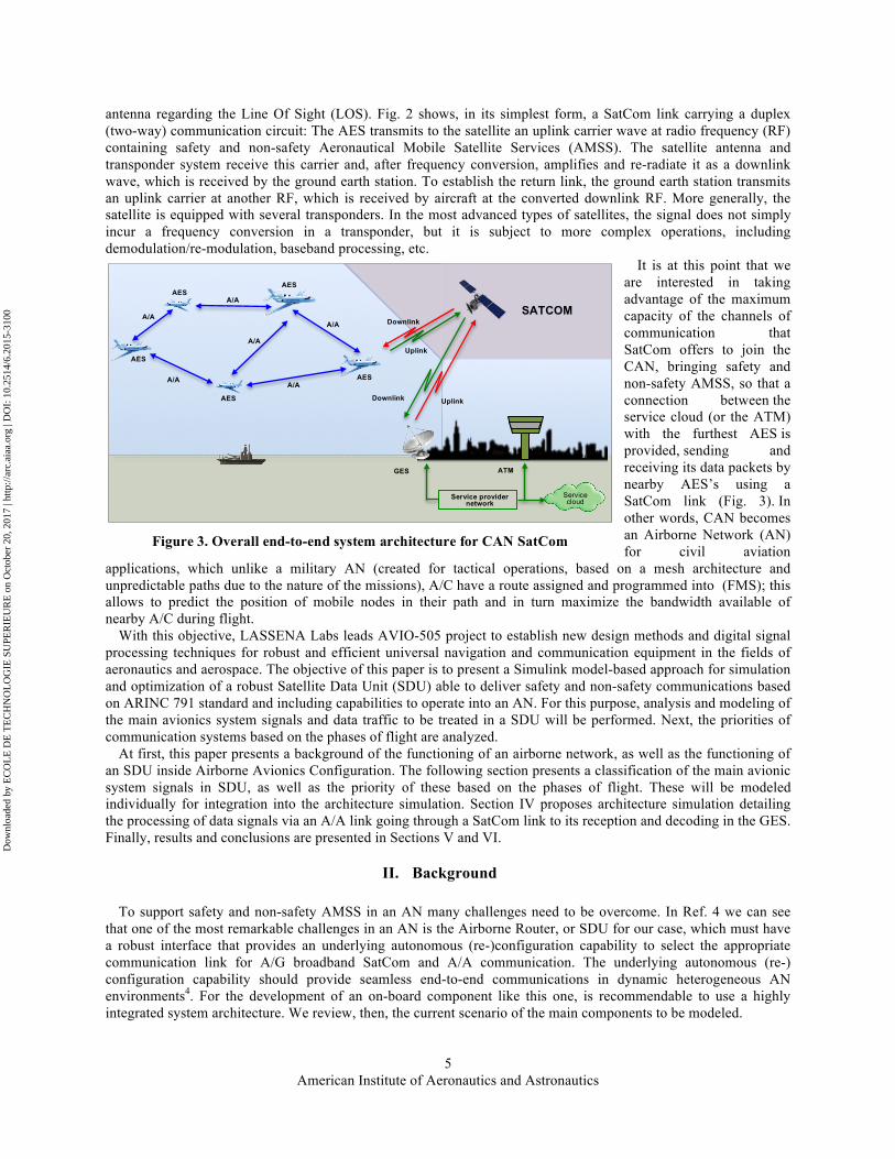
antenna regarding the Line Of Sight (LOS). Fig. 2 shows, in its simplest form, a SatCom link carrying a duplex (two-way) communication circuit: The AES transmits to the satellite an uplink carrier wave at radio frequency (RF) containing safety and non-safety Aeronautical Mobile Satellite Services (AMSS). The satellite antenna and transponder system receive this carrier and, after frequency conversion, amplifies and re-radiate it as a downlink wave, which is received by the ground earth station. To establish the return link, the ground earth station transmits an uplink carrier at another RF, which is received by aircraft at the converted downlink RF. More generally, the satellite is equipped with several transponders. In the most advanced types of satellites, the signal does not simply incur a frequency conversion in a transponder, but it is subject to more complex operations, including demodulation/re-modulation, baseband processing, etc.
It is at this point that we are interested in taking advantage of the maximum capacity of the channels of communication that SatCom offers to join the CAN, bringing safety and non-safety AMSS, so that a connection between the service cloud (or the ATM) with the furthest AES is provided, sending and receiving its data packets by nearby AES’s using a SatCom link (Fig. 3). In other words, CAN becomes an Airborne Network (AN) for civil aviation
applications, which unlike a military AN (created for tactical operations, based on a mesh architecture and unpredictable paths due to the nature of the missions), A/C have a route assigned and programmed into (FMS); this allows to predict the position of mobile nodes in their path and in turn maximize the bandwidth available of nearby A/C during flight.
With this objective, LASSENA Labs leads AVIO-505 project to establish new design methods and digital signal processing techniques for robust and efficient universal navigation and communication equipment in the fields of aeronautics and aerospace. The objective of this paper is to present a Simulink model-based approach for simulation and optimization of a robust Satellite Data Unit (SDU) able to deliver safety and non-safety communications based on ARINC 791 standard and including capabilities to operate into an AN. For this purpose, analysis and modeling of the main avionics system signals and data traffic to be treated in a SDU will be performed. Next, the priorities of communication systems based on the phases of flight are analyzed.
At first, this paper presents a background of the functioning of an airborne network, as well as the functioning of an SDU inside Airborne Avionics Configuration. The following section presents a classification of the main avionic system signals in SDU, as well as the priority of these based on the phases of flight. These will be modeled individually for integration into the architecture simulation. Section IV proposes architecture simulation detailing the processing of data signals via an A/A link going through a SatCom link to its reception and decoding in the GES. Finally, results and conclusions are presented in Sections V and VI.
II. Background
To support safety and non-safety AMSS in an AN many challenges need to be overcome. In Ref. 4 we can see that one of the most remarkable challenges in an AN is the Airborne Router, or SDU for our case, which must have a robust interface that provides an underlying autonomous (re-)configuration capability to select the appropriate communication link for A/G broadband SatCom and A/A communication. The underlying autonomous (re-) configuration capability should provide seamless end-to-end communications in dynamic heterogeneous AN environments4. For the development of an on-board component like this one, is recommendable to use a highly integrated system architecture. We review, then, the current scenario of the main components to be modeled.
AES
AES AES
AES
AES
A/A
A/A
A/A
A/A
A/A A/A
GES
Service cloud
ATM
SATCOM
Uplink Downlink
Downlink
Uplink
Service provider network
Figure 3. Overall end-to-end system architecture for CAN SatCom
Dow
nloa
ded
by E
CO
LE
DE
TE
CH
NO
LO
GIE
SU
PER
IEU
RE
on
Oct
ober
20,
201
7 | h
ttp://
arc.
aiaa
.org
| D
OI:
10.
2514
/6.2
015-
3100

American Institute of Aeronautics and Astronautics
6
A. Airborne Network (AN)
The term Airborne Network is born as part of the project called Global Information Grid (GIG) of the United States Department of Defense (US DoD), which aims to interconnect IP-based communications tactics among space, air and terrestrial segments5. “The GIG is the globally interconnected, end-to-end set of information capabilities for collecting, processing, storing, disseminating, and managing information on demand to warfighters, policy makers, and support personnel. The GIG includes owned and leased communications and computing systems and services, software (including applications), data, security services, other associated services, and National Security Systems6”.
The AN is defined as an infrastructure that provides communication transport services through backbone in-the-sky, i.e. through at least one node that is on a platform capable of flight. In Fig. 4 it is shown the AN composed of three AES, which at the same time interconnects each element of tactical missions and the Airborne Sub-Networks (fighters, helicopters, UAVs, etc.) with the Secret Internet Protocol Router Network (SIPRNET) and the Nonsecure Internet Protocol (IP) Router Network (NIPRNET). This connection can be made using DoD satellite links or commercial satellite links. This is, the AN will connect to both the space and surface networks, making it an integral part of the communications fabric of the GIG.
Table 1 identifies an objective set of communications capabilities in terms of connectivity, services and operations for the AN. All of these capabilities would not necessarily be required for every instantiation of the Airborne Network, but will be necessary to support all missions, operations, and platforms 5.
Table 1. Summary of Airborne Network Objective Capabilities 5
Network Capability & Attributes Airborne Network Objective Capabilities Connectivity Coverage Geographic span of links directly interfacing to a subject node
• Beyond Line of Sight (BLOS) extending Globally (enabling access to anywhere from anywhere)
Diversity of links Total number and types of links that can be used to “connect” to the subject node
• Number of links (system and media) matched to the mission matched to the environment (to enable guaranteed access)
• Type of links extend across the spectrum of radio frequencies including infrared and optical
Throughput Total average throughput of all links directly interfacing to the subject node
• Throughput matched to the mission and automatically adaptable to accommodate unplanned or transient conditions
• Dynamically reconfigurable to optimize performance, cost, and mission effectiveness
Tactical Mission
Commercial Satellite Link through ISP to SIPRNET or
NIPRNET
GES
Terrestrial Segment
NIPRNET Internet (ISP)
SIPRNET
Air Segment
Space Segment
Tactical Mission
NIPRNET
SIPRNET
Airborne Network
GES
DoD Satellite Link to SIPRNET or NIPRNET
Figure 4. Network architecture of Global Information Grid (GIG)
Tactical Mission
Airborne Sub-Network
AES
AES
AES
Dow
nloa
ded
by E
CO
LE
DE
TE
CH
NO
LO
GIE
SU
PER
IEU
RE
on
Oct
ober
20,
201
7 | h
ttp://
arc.
aiaa
.org
| D
OI:
10.
2514
/6.2
015-
3100

American Institute of Aeronautics and Astronautics
7
Network Capability & Attributes Airborne Network Objective Capabilities Type of connection Nature of connections that can be established between the subject nodes and directly connected nodes
• Flexible connections able to forward Globally
Network interface Networks that can be directly interfaced from the subject node (e.g., DISN (NIPRNET, SIPRNET, JWICS), Transformational Communications, TDL Networks, CDL Networks)
• Interface to AN subnet and backbone links, as well as, legacy (i.e., TDL or CDL), coalition and GIG component networks operating any version network protocol (i.e., IPv6 or IPv4), as needed
Services Real-time data Any data flows that must be sent in real time (i.e., low latency) with assured delivery (e.g., AMTI or GMTI tracks, munition terminal stage updates, RPV control, TCT&ISR tipoffs, NBC alert)
• Multiple simultaneous multilevel precedence and preemption (MLPP) real-time data links or nets, as needed
Continuous interactive voice (e.g., Voice over IP telephone and radio nets) • Multiple simultaneous MLPP voice links or nets, as needed
Continuous interactive video (e.g., Video over IP, Video Teleconferencing) • Multiple simultaneous MLPP video links, as needed
Streaming multimedia & multicast (e.g., Video imagery) • Multiple simultaneous MLPP multimedia links, as needed
Block transfer & transactional data Short blocks of interactive data (e.g., Telnet, HTTP, client/server, chat)
• Multiple simultaneous MLPP block & transactional links, as needed
Batch transfer data Long blocks of bulk data (e.g., Email, FTP) • Multiple simultaneous MLPP batch data links, as needed
Operations
Managing All aspects related to managing the links and the network including:
Planning -- frequency allocation, transmission, routing, network services and traffic.
Monitoring -- performance and use, fault, and security aspects of a link, network, or network component.
Analyzing -- performance optimization and diagnostics. Controlling -- add, remove, initialize, and configure links,
networks, or network components
• Simplified network planning to include the allocation and configuration of network resources, including legacy networks, when needed
• Automated analyses of network performance to diagnose faults, determine suboptimal conditions, and identify needed configuration changes
• Monitoring and controlling of AN link and network resources and interfaces with legacy networks
• Maintenance of network situational awareness (SA) and distribution of Network SA to peer networks
• Match use of network resources to commander’s operational objectives
Forming and Adapting To include: • Provisioning -- obtaining the needed link and network
resources. • Initialization and Restoration -- establishing or restoring a
link or network service.
• Automated provisioning, initialization and restoration of all AN link resources
Accessing All aspects related to obtaining or denying access to a link or network, to include: • Protection – communications security as well as
authentication, authorization, accounting • Detection • Reaction
• Link and subnet protection matched to the threat, with automated detection and reaction
• User data and AN management and control data protection matched to the threat
At this point we have defined an AN inside a GIG for defense purposes and previously established missions.
However this research, under the same concept, is oriented to the use of AN with civilian applications in order to maximize the use of available bandwidth in the SatCom channel AES during flight. This requires understanding the architecture and operation of hardware currently used for commercial SatCom links (to access an ISP and an ATM). Similarly, certain features of Table 1 will be used to secure services for passengers and flight safety mainly.
Due to rapid technological progress in satellite communications, private companies (service providers and on-board terminal providers) and control agencies are those who have more information, unfortunately much of this information is not published.
Dow
nloa
ded
by E
CO
LE
DE
TE
CH
NO
LO
GIE
SU
PER
IEU
RE
on
Oct
ober
20,
201
7 | h
ttp://
arc.
aiaa
.org
| D
OI:
10.
2514
/6.2
015-
3100
American Institute of Aeronautics and Astronautics
8
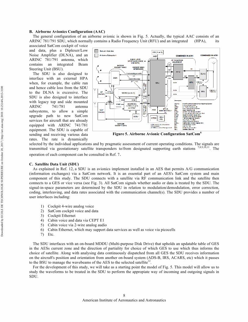
B. Airborne Avionics Configuration (AAC) The general configuration of an airborne avionic is shown in Fig. 5. Actually, the typical AAC consists of an
ARINC 781/791 SDU, which normally contains a Radio Frequency Unit (RFU) and an integrated (HPA), its associated SatCom cockpit of voice and data, plus a Diplexer/Low Noise Amplifier (DLNA), and an ARINC 781/791 antenna, which contains an integrated Beam Steering Unit (BSU).
The SDU is also designed to interface with an external HPA when, for example, the cable run and hence cable loss from the SDU to the DLNA is excessive. The SDU is also designed to interface with legacy top and side mounted ARINC 741/781 antenna subsystems, to allow a simple upgrade path to new SatCom services for aircraft that are already equipped with ARINC 741/781 equipment. The SDU is capable of sending and receiving various data rates. The rate is dynamically selected by the individual applications and by pragmatic assessment of current operating conditions. The signals are transmitted via geostationary satellite transponders to/from designated supporting earth stations 7,8,9,10,11. The operation of each component can be consulted in Ref. 7.
C. Satellite Data Unit (SDU) As explained in Ref. 12, a SDU is an avionics implement installed in an AES that permits A/G communication
(information exchanges) via a SatCom network. It is an essential part of an AES's SatCom system and main component of this study. The SDU connects with a satellite via RF communication link and the satellite then connects to a GES or vice versa (see Fig. 3). All SatCom signals whether audio or data is treated by the SDU. The signal-in-space parameters are determined by the SDU in relation to modulation/demodulation, error correction, coding, interleaving, and data rates associated with the communication channel(s). The SDU provides a number of user interfaces including:
1) Cockpit 4-wire analog voice 2) SatCom cockpit voice and data 3) Cockpit Ethernet 4) Cabin voice and data via CEPT E1 5) Cabin voice via 2-wire analog audio 6) Cabin Ethernet, which may support data services as well as voice via picocells 7) Etc.
The SDU interfaces with an on-board MDDU (Multi-purpose Disk Drive) that upholds an updatable table of GES
in the AESs current zone and the direction of partiality for choice of which GES to use which thus informs the choice of satellite. Along with analysing data continuously dispatched from all GES the SDU receives information on the aircraft's position and orientation from another on-board system (ADS-B, IRS, ACARS, etc) which it passes to the BSU to manage the wavebeams of the AES to the selected satellite12.
For the development of this study, we will take as a starting point the model of Fig. 5. This model will allow us to study the waveforms to be treated in the SDU to perform the appropiate way of incoming and outgoing signals in SDU.
Figure 5. Airborne Avionic Configuration SatCom6
Dow
nloa
ded
by E
CO
LE
DE
TE
CH
NO
LO
GIE
SU
PER
IEU
RE
on
Oct
ober
20,
201
7 | h
ttp://
arc.
aiaa
.org
| D
OI:
10.
2514
/6.2
015-
3100
American Institute of Aeronautics and Astronautics
9
III. Signal generation and priority of communications In order to modeling a robust SDU for AN we need to know what kind of signals will be treated within this unit, as
well as the priority they have. These signals contain information automatically extracted from the data bus (or in other cases is information entered manually by the crew of AES) to be sent via radio or via satellite to Air Traffic Control (ATC) or to GES. Similarly data from IFC service offered to passengers are treated in this device for sending via satellite to the cloud service. That is why at this point we are going to model and analyze the signals to be treated in our SDU model.
A. Main avionic system signals in SDU As seen in Fig. 5, SDU function is to transmit, receive and process signals via SatCom providing AMSS between
AES and GES in Ku or Ka band, however it is important to differentiate these services8,9. 1) Safety AMSS, are communications services that require high integrity and quick reponse, these include:
a. Safety-related communications carried out by the Air Traffic Services (ATS) for ATC, flight information and alerting
b. Communications carried out by aircraft operators, which also affect air transport safety, regularity and efficiency (Aeronautical Operational Control (AOC))
2) Non-Safety AMSS, are communications services that do not compromise flight safety, these include a. Private correspondence of aeronautical operators (Aeronautical Administrative
Communications (AAC)) b. Public correspondence (Aeronautical Passenger Communications (APC) including IFC).
Table 2. Summary of safety and non-safety AMSS8
AMSS APC AAC AOC ATS
Non-Safety ✓ ✓ ✓ Safety ✓ ✓
Table 2 shows the summarized classification of AMSS. Non-safety AMSS may be authorized by administrations
in certain frequency bands allocated, as long as they cease immediately, if necessary, to permit transmission of messages for safety and regularity of flights (i.e. ATS and AOC, according to priority 1 to 6 of Article 51 of ITU Radio Regulations).9,13
For purposes of this publication, we will consider mainly three kinds of communication systems: 1) ACARS, 2) ADS-B and 3) IFC. These will be processed by the SDU. For which ACARS and ADS-B will be classified as safety AMSS and IFC will be classified as non-safety AMSS. Following we will see the description of the generation of safety AMSS signals.
1) Aircraft Communications Addressing and Reporting System (ACARS)
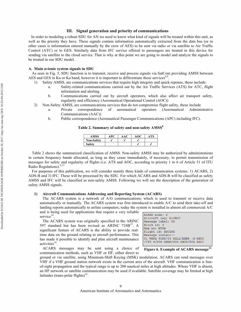
The ACARS system is a network of A/G communications; which is used to transmit or receive data automatically or manually. The ACARS system was first introduced to enable A/C to send their take-off and landing reports automatically to airline computers; today the system is installed in almost all commercial A/C and is being used for applications that require a very reliable service14.
The ACARS system was originally specified in the ARINC 597 standard but has been revised as ARINC 724B15. A significant feature of ACARS is the ability to provide real-time data on the ground relating to aircraft performance. This has made it possible to identify and plan aircraft maintenance activities16.
ACARS messages may be sent using a choice of communication methods, such as VHF or HF, either direct to ground or via satellite, using Minimum-Shift Keying (MSK) modulation. ACARS can send messages over VHF if a VHF ground station network exists in the current area of the aircraft. VHF communication is line-of-sight propagation and the typical range is up to 200 nautical miles at high altitudes. Where VHF is absent, an HF network or satellite communication may be used if available. Satellite coverage may be limited at high latitudes (trans-polar flights)16.
Figure 6. Example of ACARS message16
Dow
nloa
ded
by E
CO
LE
DE
TE
CH
NO
LO
GIE
SU
PER
IEU
RE
on
Oct
ober
20,
201
7 | h
ttp://
arc.
aiaa
.org
| D
OI:
10.
2514
/6.2
015-
3100

American Institute of Aeronautics and Astronautics
10
a) ACARS Message A typical ACARS message (see Fig. 6) consists of:
• mode identifier (e.g. 2) • aircraft identifier (e.g. G-DBCC) • message label (e.g. 5U) • block identifier (e.g. 4) • message number (e.g. M55A) • flight number (e.g. BD01NZ) • message content (see Fig. 6).
The data rate is low and messages comprise plain alphanumeric characters. Frequencies used for the transmission and reception of ACARS messages are in the band extending from 129 MHz to 137 MHz (VHF). Different channels are used in different parts of the world15.
b) ACARS Message Structure
The structure of the ACARS message is detailed in the standard ARINC 61817. In the following tables (Table 3 and 4), the structures of the A/G Downlink and G/A messages are summarized, which will be used later.
Table 3. General format of A/G downlink message
Name SOH Mode Aircraft Registration Number
TAK Label DBI STX MSN Flight ID Application Text Suffix BCS BCS Suffix
Size 1 1 7 1 2 1 1 4 6 0-210 1 2 1 Example <SOH> 2 .N123XX 5Z 2 <STX> M01A XX0000 <ETX> <DLE>
Table 4. General format of G/A uplink message
Name SOH Mode Aircraft Registration or Flight ID
TAK Label UBI STX Application Text Suffix BCS BCS Suffix
Size 1 1 7 1 2 1 1 0-210 1 2 1 Example <SOH> 2 .N123XX 5Z 2 <STX> <ETX> <DLE>
c) Data Coding
The data exchanged between the ACARS MU and the VHF radio (Fig.5) are by 1.2 and 2.4 KHz tones (Fig. 7). A zero-bit is coded: - By a positive half period of 1.2 KHz when it is the first of a string of zero-bits (even if the string only comprises this single bit. - By a 2.4 KHz period starting by the
negative half period when this is not the case
A one-bit is coded: - By a negative half period of 1.2 KHz when it is the first of a string of one-bits (even if the string only comprises this single bit). - By a 2.4 KHz period starting by the positive half period when this is not the case.
The transmission rate of this coding is 2.4 Kbps from aircraft to ground and vice versa. The
transmitted data are characters from the ISO alphabet No.5 except the block check sequence field at the end of transmission (Table 5).
1 2 3 4 5 6 7 8 9 10 11
0 1 0 0 1 1 1 0 0 1 0
Bit order
Message
Waveform
1.2 KHz 2.4 KHz
Figure 7. ACARS Data Coding
Dow
nloa
ded
by E
CO
LE
DE
TE
CH
NO
LO
GIE
SU
PER
IEU
RE
on
Oct
ober
20,
201
7 | h
ttp://
arc.
aiaa
.org
| D
OI:
10.
2514
/6.2
015-
3100

American Institute of Aeronautics and Astronautics
11
Table 5. ACARS – ISO Alphabet No.517
b7 0 0 0 0 1 1 1 1 Bits b6 0 0 1 1 0 0 1 1 b5 0 1 0 1 0 1 0 1
b4 b3 b2 b1 ROW COLUMN Acronyms 0 1 2 3 4 5 6 7
0 0 0 0 0 NUL DLE SP 0 @ P ` p ACK Acknowledge GS Group Separator 0 0 0 1 1 SOH DC1 ! 1 A Q a q BEL Bell HT Horizontal Tabulation 0 0 1 0 2 STX DC2 " 2 B R b r BS Backspace LF Line Feed 0 0 1 1 3 ETX DC3 # 3 C S c s CAN Cancel NAK Negative Acknowledgment 0 1 0 0 4 EOT DC4 $ 4 D T d t CR Carriage Return NUL Null 0 1 0 1 5 ENQ NAK % 5 E U e u DC Device Control RS Record Separator 0 1 1 0 6 ACK SYN & 6 F V f v DEL Delete SI Shift-In 0 1 1 1 7 BEL ETB ‘ 7 G W g w DLE Data Link Space SO Shift-Out 1 0 0 0 8 BS CAN ( 8 H X h x EM End Of Medium SOH Start Of Heading 1 0 0 1 9 HT EM ) 9 I Y i y ENQ Enquiry SP Space 1 0 1 0 10 LF SUB * : J Z j z EOT End Of Transmission STX Start Of Text 1 0 1 1 11 VT ESC + ; K [ k { ESC Escape SUB Substitute 1 1 0 0 12 FF FS , < L \ l | ETB End Of Tx Block SYN Synchronous Idle 1 1 0 1 13 CR GS - = M ] m } ETX End Of Text US Unit Separator 1 1 1 0 14 SO RS . > N ^ n ~ FF Form Feed VT Vertical Tabulation 1 1 1 1 15 SI US / ? O _ o DEL FS File Separator
d) ACARS message generator
To accomplish ACARS messages to be generated, we rely on the ARINC 618, 619, 620 and 724 standards17,18,19. The first step is to make the MSK modulation according to the specifications described above. MSK can be thought of as a special case of OQPSK (Offset Quadrature Phase Shift Keying) with sinusoidal pulse weighting17. Consider the OQPSK signal, with the bit streams offset; the resulting signal is represented by Equation 1.
! ! ! !! ! !"#!"!! !"#! !!!!! ! !! ! !"# !"
!! !"#! !!!!! (1)
Where !! is the carrier frequency and !! ! and !! ! encode the even and odd information respectively with a sequence of square pulses of duration !!. !! ! !has its pulse edges on ! ! !!!!!! !!! !!! ! ! ! and !! ! on ! ! !!! !!! !!! !!! ! ! !. Using the trigonometric identity, this can be rewritten in a form where the phase and frequency modulation are more obvious20.
Where !! ! is !! when !!!!! !! !!!!!!!and !! if they are of opposite signs, and !! is ! if !!!!! is !, and ! otherwise. Therefore, the signal is modulated in
frequency and phase, and the phase changes continuously and linearly. First thing is the implementation of our MSK modulator, always respecting the periods for a
one or zero-bit (ACARS_SignalGenerator function). Thus we obtain as a result the waveforms of Fi. 9.a., which are comparable with the waveform shown in Fig. 7.
Next we develop the ACARS message generator, which will aim to convert into in bits (ACARS_ExtractBits function) the ACARS message structure A/G based in Tables 3 and 4.
Each message frame consists of at least 50, and up to a maximum of 272 characters or bytes. Each character uses a 7-bit ACSII (from ISO alphabet No.5) code with an additional eighth parity bit. Bit 8 is an odd parity bit used for the text field of the ACARS message, and the content may be free text or a mixture of formatted and free text16. For this, the function "ACARS_AddOddParity" which performs this action was implemented.
The sixteen pre-key characters are all binary 1 values, thus resulting in the 0.05 second 2400 Hz beep that can be heard at the start of every message.
! ! ! !"#! !!!!! ! !! !!"!! ! !! (2)
* *
* *
!"#!!!!!!
!"#!!!!!!
!"#!!!!!! ! !!!
!"#!!!!!! ! !!!
!!! !!!! !!!!!!!!
!!!!!!!!! !!!!!!!!
!!!!! !! !!!
! !!!
! !!!
!!!
Figure 8. Signal space diagram for QPSK and OPSK
Dow
nloa
ded
by E
CO
LE
DE
TE
CH
NO
LO
GIE
SU
PER
IEU
RE
on
Oct
ober
20,
201
7 | h
ttp://
arc.
aiaa
.org
| D
OI:
10.
2514
/6.2
015-
3100

American Institute of Aeronautics and Astronautics
12
The Block Check Sequence field contains the value of an error-detection polynomial that can be used to determine if the entire message was received free of errors.
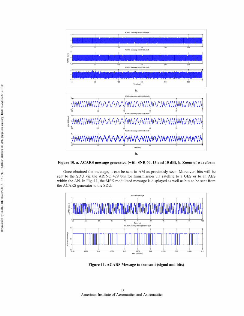
Thus we also use the function "AWGN" to add white Gaussian noise to the ACARS message. The scalar SNR specifies the signal-to-noise ratio per sample, in dB. In this way, we can show the message generated by our ACARS message generator including different SNR values of 10, 30 and 60 dB (Fig. 10). The impact generated by the Gaussian noise on the generated signal can be seen in the figure below which shows the signals in an interval of time (50 to 75 ms).
a.
Figure 9 a. Waveform from MSK modulator, b. Extract of code of ACARS messages generator
0 2 4 6
x 10-4
0
0.2
0.4
0.6
0.8
1Zero-bit 1.2 KHz
Time
0 2 4 6
x 10-4
-1
-0.8
-0.6
-0.4
-0.2
0One-bit 1.2 KHz
Time
0 2 4 6
x 10-4
-1
-0.5
0
0.5
1Zero-bit 2.4 KHz
Time0 2 4 6
x 10-4
-1
-0.5
0
0.5
1One-bit 2.4 KHz
Time
%%%%%%%%%%%%%%%%%%%%%%%%%%%%%%%%%%%%%%%%%%%%%% % ACARS character definition DLE = hex2dec('10'); NAK = hex2dec('15'); SYN = hex2dec('16'); SOH = hex2dec('01'); STX = hex2dec('02'); ETX = hex2dec('03'); ACK = hex2dec('06'); DEL = hex2dec('7F'); % ACARS message components Preamble = 255*ones(1,16); % Preamble BitSync = '+*' -0; CharSync = [SYN SYN]; StartOfHeading = SOH; Mode = '2'-0; Address = '.LKC693'-0; TechAck = NAK; Label = 'Q0'-0; BlockID = '5'-0; STXETX = STX; FlightNo = 'AG1979'-0; Text = 'This is a message from Lassena Laboratory'-0; BlockCheckSequence = '@'-0; BCS_Suffix = DLE; % ACARS message structure MessageWithoutPreamble = [BitSync CharSync StartOfHeading Mode Address ... TechAck Label BlockID STXETX FlightNo Text ETX ... BlockCheckSequence BCS_Suffix]; MessageWithParity = ACARS_AddOddParity(MessageWithoutPreamble); MessageBits = ACARS_ExtractBits([Preamble MessageWithParity]); Fs = 96000; BasebandSignal = ACARS_SignalGenerator(MessageBits,Fs); BasebandSignal = awgn(BasebandSignal,60,'measured'); BasebandSignal = [zeros(1,100) BasebandSignal zeros(1,100)];
b.
Dow
nloa
ded
by E
CO
LE
DE
TE
CH
NO
LO
GIE
SU
PER
IEU
RE
on
Oct
ober
20,
201
7 | h
ttp://
arc.
aiaa
.org
| D
OI:
10.
2514
/6.2
015-
3100
American Institute of Aeronautics and Astronautics
13
a.
b.
Figure 10. a. ACARS message generated (with SNR 60, 15 and 10 dB), b. Zoom of waveform
Once obtained the message, it can be sent in AM as previously seen. Moreover, bits will be sent to the SDU via the ARINC 429 bus for transmission via satellite to a GES or to an AES within the AN. In Fig. 11, the MSK modulated message is displayed as well as bits to be sent from the ACARS generator to the SDU.
Figure 11. ACARS Message to transmit (signal and bits)
0 50 100 150 200 250-2
0
2ACARS Message with SNR=60dB
0 50 100 150 200 250-2
0
2
AC
AR
S S
igna
l
ACARS Message with SNR=30dB
0 50 100 150 200 250-2
0
2
Time (ms)
ACARS Message with SNR=10dB
50 55 60 65 70 75-2
0
2ACARS Message with SNR=60dB
50 55 60 65 70 75-2
0
2
AC
AR
S S
igna
l
ACARS Message with SNR=30dB
50 55 60 65 70 75-2
0
2
Time (ms)
ACARS Message with SNR=10dB
50 55 60 65 70 75 80 85 90 95 100-2
-1
0
1
2ACARS Message
Time(ms)
AC
AR
S s
igna
l
0.05 0.055 0.06 0.065 0.07 0.075 0.08 0.085 0.09 0.095 0.1-0.5
0
0.5
1
1.5
Time (seconds)
AC
AR
S m
essa
ge
Bits from ACARS Message to the SDU
Dow
nloa
ded
by E
CO
LE
DE
TE
CH
NO
LO
GIE
SU
PER
IEU
RE
on
Oct
ober
20,
201
7 | h
ttp://
arc.
aiaa
.org
| D
OI:
10.
2514
/6.2
015-
3100
American Institute of Aeronautics and Astronautics
14
2) Automatic Dependent Surveillance – Broadcast (ADS-B) ADS-B is a surveillance technique in which an AES transmits via a data link a number of parameters
extracted from the navigation and positioning systems on board. The idea is therefore that the AES, equipped with a Global Positioning System (GPS), calculates its own
data (identity, position, speed, intent, altitude, etc.) and sends it regularly by radio (1090 MHz) to GSs and other AES equipped with ADS-B that are present in the flight area. This new system is especially useful to complement surveillance in oceanic areas or where there is virtually no radar coverage, as well as to improve surveillance in areas currently covered by radar.
ADS-B has two fundamental characteristics: it is automatic, that is, does not need the intervention of the pilot for AES data to be sent to the control tower; and is dependent, because the necessary information is generated in the same AES, that is dependent on onboard systems.
a) ADS-B IN and ADS-B OUT
ADS-B IN concerns the reception of ADS-B messages transmitted by other AES. In this case, the AES is also equipped with a Cockpit Display of Traffic Information (CDTI) to display ADS-B OUT messages from other AES and information sent from GSs. The information displayed on the CDTI can be combined with information from other systems, such as aeronautical charts, contour lines, and data from Traffic Information Services - Broadcast (TIS-B) and Flight Information System - Broadcast (FIS-B)21.
ADS-B OUT concerns transmission of ADS-B messages by AES. An ADS-B transmitter can send the position, altitude and identification of an AES to GSs to be analyzed and displayed on the screens of ATC. The ADS-B signal is broadcast from the AES approximately twice per second, and in the event the AES is within the coverage radius of an ADS-B GSs, data is transmitted to ATM facilities21.
b) ADS-B message structure
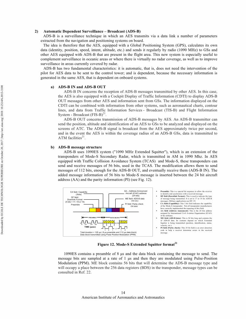
ADS-B uses 1090ES system ("1090 MHz Extended Squitter"), which is an extension of the transponders of Mode-S Secondary Radar, which is transmitted in AM in 1090 Mhz. In AES equipped with Traffic Collision Avoidance System (TCAS) and Mode-S, these transponders can send and receive messages of 56 bits, used in the TCAS. The modification allows them to send messages of 112 bits, enough for the ADS-B OUT, and eventually receive them (ADS-B IN). The added message information of 56 bits to Mode-S message is inserted between the 24 bit aircraft address (AA) and the parity information (PI) (see Fig. 12).
Figure 12. Mode-S Extended Squitter format21
1090ES contains a preamble of 8 µs and the data block containing the message to send. The
message bits are sampled at a rate of 1 µs and then they are modulated using Pulse-Position Modulation (PPM). ME block contains 56 bits that will determine the ADS-B message type and will occupy a place between the 256 data registers (BDS) in the transponder, message types can be consulted in Ref. 22.
! Preamble: This is a special bit sequence to allow the receiver to identify and synchronize with a received message.
! DF field (Downlink Format): This is used to indicate the type of message being transmitted. It is set to 17 or 18 for ADS-B messages. Military applications use DF=19.
! CA field (Capability): This 3 bit field indicates the capability of the Mode-S transponder. Not all transponder manufacturers have correctly implemented the reporting of this field.
! AA field (Address Announced): This is the 24 bits address assigned by International Civil Aviation Organization (ICAO) of the airframe.
! ME field (ADS-B data): This is 56 bits long and contains the of ADS-B data. Its contents depend on which Extended Squitter is being transmitted (position, identification, status, velocity, etc.).
! PI field (Parity check): This 24 bit field is an error detection code to help a receiver determine errors in the received message.
Preamble
DF field: Downlink Format
(5 bits = 17, 18 or 19)
CA field: Capability (3bits)
AA – Address Announced Aircraft (ICAO) address
(24 bits) ME field: ADS-B data
(56 bits) PI field: Parity check
(24 bits)
PREAMBLE DATA BLOCK
1 0 1 0 1 0 1 0 1 0
⁄ ⁄
⁄ ⁄ 0 1.0 3.5 4.5
TIME (µsec) 1 0 1 1 0
Total duration = 120 µs ( 8 µs preamble and 112 µs data block) Data block transmitted using Pulse Position Modulation (PPM). D
ownl
oade
d by
EC
OL
E D
E T
EC
HN
OL
OG
IE S
UPE
RIE
UR
E o
n O
ctob
er 2
0, 2
017
| http
://ar
c.ai
aa.o
rg |
DO
I: 1
0.25
14/6
.201
5-31
00

American Institute of Aeronautics and Astronautics
15
Table 6. Content of some BDS registers21
REGISTER! MESSAGE ADS-B!
BDS 05h! Airborne Position Message!BDS 06h! Surface Position Message !BDS 08h! Aircraft Identification (ID) and Category Message !BDS 09h! Airborne Velocity Message !BDS 61h! Emergency/Priority Status Message!BDS 62h! Target State and Status Message !BDS 65h! Aircraft Operational Status Message!
Table 6 shows registers commonly used for ADS-B. The registers are identified by two
hexadecimal digits, e.g. BDS 05h (or BDS 0.5) is the squitter used for transmitting the AES position21.
c) ADS-B message generator
To create the ADS-B messages we will use the model of Ref. 21 (Fig. 13) based on Ref. 21 the idea is to get the bits of the ADS-B message with a total length of 120 µs, taking into consideration the preamble (8 µs) and message length (112 µs).
The model shows the block "ADS-B signal generator" which is linked to block "ADS-B message". This block allows building any
ADS-B message type by manually entering data in hexadecimal format (4bits) from the ADS-B data entry graphical interface (Fig. 14). This model simulates step by step the treatment of ADS-B message from its creation (simulating the extraction of 4D data manually), generating bits, inserting the preamble at the beginning of the data block previously modulating in PPM. Then this message is sent to AM modulator for transmission in 1090 MHz. The model also allows adding Gaussian noise. The results of oscilloscopes signals are shown in Fig. 15.
Figure 15. Waveform of processing ADS-B message
1.38 1.4 1.42 1.44 1.46 1.48 1.5
x 10-3
0.5
1
ADS-B Message with PPM
1.38 1.4 1.42 1.44 1.46 1.48 1.5
x 10-3
-10
0
10
ADS-B Message with AM (Carrier = 1090 MHz)
1.38 1.4 1.42 1.44 1.46 1.48 1.5
x 10-3
-20
0
20ADS-B Message and noise added
Time (seconds)
Figure 14. ADS-B data entry
Dow
nloa
ded
by E
CO
LE
DE
TE
CH
NO
LO
GIE
SU
PER
IEU
RE
on
Oct
ober
20,
201
7 | h
ttp://
arc.
aiaa
.org
| D
OI:
10.
2514
/6.2
015-
3100

American Institute of Aeronautics and Astronautics
16
Once obtained the ADS-B message, it can be sent in AM as discussed above. Moreover, bits will be sent to the SDU for transmission via satellite to a GES or an AES within the AN. In Fig. 15, PPM modulated message is displayed; as well as bits to be sent from the ADS-B message generator to the SDU.
3) In-Fligth Connectivity (IFC)
In-Flight Connectivity is a term which we derive from In-Flight Entertainment and Communications (IFEC) which comprises a broad gamma of services offered to passengers (audio, video, Wi-Fi, etc.) during the flight. IFC system comprises data service like Wi-Fi and mobile telephony that helps the passengers keep in constant touch with people on ground.
To generate the signal IFC we will use a Bernoulli Binary Generator (BBG) of the Simulink library that generates random binary numbers using a Bernoulli distribution. An important and little known element to consider is the mean data rate that generates an AES2. Table 7 shows minimum and maximum expected mean data rate per A/C type and number of passengers for IFC projected for 2020.
Table 7. Number of passengers, minimum and maximum expected mean data rate per A/C type2
A/C Number of passengers
Minimum expected mean data rate
(Mbps)
Maximum expected mean
data rate (Mbps) A320 150 - 180 52.43 62.91 A330 253 - 440 88.43 153.79 A350 270 - 550 94.37 192.23 A380 555 - 853 193.98 298.14 B737 85 - 215 29.71 75.15 B777 301 – 550 105.20 192.23 B787 210 – 330 73.40 115.34 B747 467 - 605 163.22 211.46
As we can see, in terms of data rate, for IFC, these could be from 29.71 Mbps and up to 300 Mbps
approximately. These values will allow setting the sample time at the BBG to 33.66 ns for a data rate of 29.71 Mbps or 3.33 ns for a data rate of 300 Mbps.
B. Priority of communication system based on the phases of flight The priority of communications during the flight is determined by the degree of commitment to flight safety. For
this purpose ACARS and ADS-B are used during all phases of flight (as AMSS) as these services contain information of the state of AES as well as the 4D information for better control from the ATC, unlike IFC which contains only communications for passengers. In Fig. 16 the activity of these services is appreciated according to the flight phase.
Taxi Take-Off Departure En Route (ENR) Approach Land Taxi ACARS
ADS-B in/Out - - - IFC - - -
Figure 16. ACARS, ADS-B and IFC availability during flight phases
However, the use of these services has failed to prevent the recent events that have afflicted the aviation industry.
That is why government agencies are forced to use more and more satellite channels to register the route.
APT (Airport)
APT (Airport)
TMA (Terminal Maneuvering Area)
TMA (Terminal Maneuvering Area)
ENR/ORP (Oceanic Remote Polar)
Dow
nloa
ded
by E
CO
LE
DE
TE
CH
NO
LO
GIE
SU
PER
IEU
RE
on
Oct
ober
20,
201
7 | h
ttp://
arc.
aiaa
.org
| D
OI:
10.
2514
/6.2
015-
3100

American Institute of Aeronautics and Astronautics
17
IV. Simulation architecture The simulation model of the SDU inside an AES for AN, is based on a one-way communication by sending
Safety and Non-Safety information from AES to GES using a SatCom channel. In Fig. 17 the stage of the simulation as well as the architecture of the Simulink model is shown. This architecture allows us to transmit simulation data from ACARS, ADS-B and IFC message generators, obtained in the previous point, from the SDU of the Neighboring AES (NAES) to the SDU of the AES (Fig. 18). The AES immediately will send the data received by adding their own data; that is, the goal is to ensure not only the sending of the messages of AES in AN but also data from NAES via AMSS. This link is performed considering the random noise which is added in the transmission and controlling the Signal-to-noise Ratio (SNR) for simulation purposes23.
Should be mentioned that both the NAES SDU and the AES SDU have the ability to make an own SatCom link. However the proposed scenario assumes that the AES SDU account not only with greater capacity and better SNR within the AN but also with availability in terms of
traffic, Bandwidth (BW) and QoS. In a real scenario, the SDU must have resource allocation techniques enabling it to verify and assign the size,
availability and QoS communication channel to share. This could be implemented in a Software Defined Radio (SDR). SDRs are advantageous; because with software routines are enough for: switching to other wireless protocols, integrate new standards in aircrafts without substantial cost, develop monitoring tools to guarantee QoS, processing signals for more efficiently use of spectrum, ensuring the scalability and reconfigurability of system.
A. Signal processing inside SDUs Within our SDU, one of the problems is how to
distribute between various systems (ACARS, ADS-B and IFC) using a single channel of communication via AMSS, so they can manage several messages simultaneously. Without an organized approach, there will appear interferences that may well prove troublesome, or directly impede communication. This
concept is called multiplexing or media access control, depending on context as such.
To solve it, we will use a spread spectrum technology and a special coding scheme, whereby each message generator will assign a unique code, chosen so that it is orthogonal to the rest (Fig. 19). It is worth mentioning that in this study we are not going to develop the RF aspect but rather the treatment of signal through the SDU. To do so, inside the SDU each entry is multiplied by Gold codes or Gold sequences (which is useful when multiple devices are broadcasting in the same frequency range). In Fig. 19 we can observe that each input, as well as for NAES (up) and AES (down), there is a Gold sequence generator block. Gold sequences are unique for each SDU input and is emitted with a bandwidth significantly higher than data.
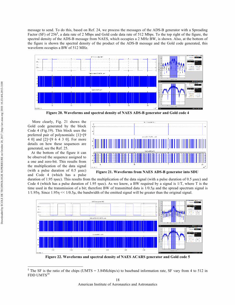
Take, for example, Fig. 20, here the waveforms of the ADS-B message from the NAES (ADSB_AES2 label in Fig.19) are shown, the message after being multiplied by its assigned Gold code (Code 4) is also shown. You can see the preamble of the ADS-B message and part of the
Figure 18. Signals to processing by SDUs in AN
Figure 19. SDU architectures (NAES and AES)
GES
Service cloud
ATM
AES
Aeronautical SatCom System
ACARS ADS-B
IFC
Service provider network
Safety and Non-Safety
AMSS
Neighboring AES
Figure 17. Simulation architecture and scenario
Dow
nloa
ded
by E
CO
LE
DE
TE
CH
NO
LO
GIE
SU
PER
IEU
RE
on
Oct
ober
20,
201
7 | h
ttp://
arc.
aiaa
.org
| D
OI:
10.
2514
/6.2
015-
3100
American Institute of Aeronautics and Astronautics
18
message to send. To do this, based on Ref. 24, we process the messages of the ADS-B generator with a Spreading Factor (SF) of 256§, a data rate of 2 Mbps and Gold code data rate of 512 Mbps. To the top right of the figure, the spectral density of the ADS-B message from NAES, which occupies a 2 MHz BW, is shown. Also, at the bottom of the figure is shown the spectral density of the product of the ADS-B message and the Gold code generated, this waveform occupies a BW of 512 MHz.
Figure 20. Waveforms and spectral density of NAES ADS-B generator and Gold code 4
More clearly, Fig. 21 shows the
Gold code generated by the block Code 4 (Fig.19). This block uses the preferred pair of polynomials: [1]=[9 4 0] and [2]=[9 6 4 3 0]. For more details on how these sequences are generated, see the Ref. 25.
At the bottom of the figure it can be observed the sequence assigned to a one and zero-bit. This results from the multiplication of the data signal (with a pulse duration of 0.5 µsec) and Code 4 (which has a pulse duration of 1.95 !sec). This results from the multiplication of the data signal (with a pulse duration of 0.5 µsec) and Code 4 (which has a pulse duration of 1.95 !sec). As we know, a BW required by a signal is 1/T, where T is the time used in the transmission of a bit; therefore BW of transmitted data is 1/0.5µ and the spread spectrum signal is 1/1.95!. Since 1.95! << 1/0.5µ, the bandwidth of the emitted signal will be greater than the original signal.
Figure 22. Waveforms and spectral density of NAES ACARS generator and Gold code 5
§ The SF is the ratio of the chips (UMTS = 3.84Mchips/s) to baseband information rate, SF vary from 4 to 512 in FDD UMTS24
Figure 21. Waveforms from NAES ADS-B generator into SDU
Dow
nloa
ded
by E
CO
LE
DE
TE
CH
NO
LO
GIE
SU
PER
IEU
RE
on
Oct
ober
20,
201
7 | h
ttp://
arc.
aiaa
.org
| D
OI:
10.
2514
/6.2
015-
3100
American Institute of Aeronautics and Astronautics
19
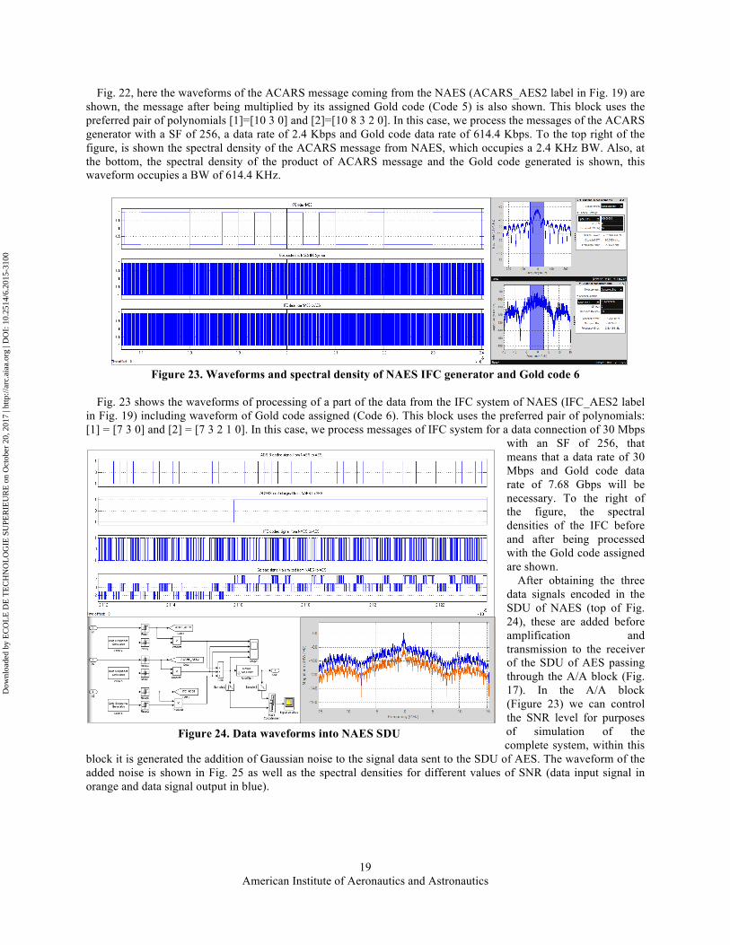
Fig. 22, here the waveforms of the ACARS message coming from the NAES (ACARS_AES2 label in Fig. 19) are shown, the message after being multiplied by its assigned Gold code (Code 5) is also shown. This block uses the preferred pair of polynomials [1]=[10 3 0] and [2]=[10 8 3 2 0]. In this case, we process the messages of the ACARS generator with a SF of 256, a data rate of 2.4 Kbps and Gold code data rate of 614.4 Kbps. To the top right of the figure, is shown the spectral density of the ACARS message from NAES, which occupies a 2.4 KHz BW. Also, at the bottom, the spectral density of the product of ACARS message and the Gold code generated is shown, this waveform occupies a BW of 614.4 KHz.
Figure 23. Waveforms and spectral density of NAES IFC generator and Gold code 6
Fig. 23 shows the waveforms of processing of a part of the data from the IFC system of NAES (IFC_AES2 label
in Fig. 19) including waveform of Gold code assigned (Code 6). This block uses the preferred pair of polynomials: [1] = [7 3 0] and [2] = [7 3 2 1 0]. In this case, we process messages of IFC system for a data connection of 30 Mbps
with an SF of 256, that means that a data rate of 30 Mbps and Gold code data rate of 7.68 Gbps will be necessary. To the right of the figure, the spectral densities of the IFC before and after being processed with the Gold code assigned are shown.
After obtaining the three data signals encoded in the SDU of NAES (top of Fig. 24), these are added before amplification and transmission to the receiver of the SDU of AES passing through the A/A block (Fig. 17). In the A/A block (Figure 23) we can control the SNR level for purposes of simulation of the complete system, within this
block it is generated the addition of Gaussian noise to the signal data sent to the SDU of AES. The waveform of the added noise is shown in Fig. 25 as well as the spectral densities for different values of SNR (data input signal in orange and data signal output in blue).
Figure 24. Data waveforms into NAES SDU
Dow
nloa
ded
by E
CO
LE
DE
TE
CH
NO
LO
GIE
SU
PER
IEU
RE
on
Oct
ober
20,
201
7 | h
ttp://
arc.
aiaa
.org
| D
OI:
10.
2514
/6.2
015-
3100

American Institute of Aeronautics and Astronautics
20
In Fig. 26, the processing of the data signals within the AES SDU is shown. The result of the A/A block, to be received in the receiver AES SDU, will be multiplied with the Code 3 block and this in turn will again be added to the signals resulting from the data signals Safety AMSS (which is multiplied by the Code 1 block) and Non-Safety AMSS (which is multiplied by the Code 2 block) of AES.
The BW of the transmitted signal will be directly proportional to the highest data rate required by systems to transmit, that means in the case of the SDU of NAES the BW will be 7.68 GHz as shown in the spectral density of Fig. 24. As we can see, the IFC is the AMSS that demands largest/highest BW,
in other words it is what determines our SDU BW within an AN. This means also that to comply with the maximum estimated capacity of Table 7, it would require a bigger BW in 2020.
Inside the AES SDU, we find the same internal architecture as the NAES SDU with the difference that this SDU has a channel that allows the reception and forwarding of the received signal. The implementation of AES SDU in a physical platform suggests mainly check availability in terms of traffic, BW and QoS, in order to not compromise its own connection.
B. Reciving and decoding After passing through the SatCom block, which consists of the same architecture as the A/A block (in order to
control the SNR) the data signal of the SDU arrives at GES. In Fig. 27, we can see the spectral densities at the receiver for different values of SNR (10, 20 and 30) and SF (256 and 8).
Figure 25. A/A block for SNR = -20, 0 and 20 dB
SNR = -20 dB SNR = 0 dB
SNR = 20 dB
!"#$%&'()*#+,-%.)/0)'**#*)+/-,#))
Figure 26. Spectral densities into AES SDU
!"#$%&'()*#+,-%.)/0)!'0#%.)12!!)*'%'),-3+'()!"#$%&'()*#+,-%.)/0)!'0#%.)12!!)*'%'),-3+'()4-%5)6/(*)$/*#)7)
!"#$%&'()*#+,-%.)/0)8'%'),-3+'()'9"(-0-#*):;(<#=)%/),#+*)%/)6>!)?-')!'%@/9))))
Dow
nloa
ded
by E
CO
LE
DE
TE
CH
NO
LO
GIE
SU
PER
IEU
RE
on
Oct
ober
20,
201
7 | h
ttp://
arc.
aiaa
.org
| D
OI:
10.
2514
/6.2
015-
3100

American Institute of Aeronautics and Astronautics
21
b.
Figure 27. a. Spectral densities in GES receptor for differents SNR values (10 20 and 30) with SF = 256 b. Spectral densities in GES receptor for differents SNR values (10 20 and 30) with SF = 8
The next step is to recover the signals sent, which is done by cross-correlation of captured signal with the code of
the system of interest, as well as the rejection of the rest of signals and interferences produced in the transmission of the source signal25.
In signal processing, the cross-correlation (or sometimes called "cross-covariance") is a measure of the similarity between two signals, often used to find relevant features in an unknown signal by comparison with other that it is known. It is a function of the relative time between the signals, sometimes is also called scalar product displaced, and has applications in pattern recognition and cryptanalysis.
Figure 28. Decoded signals at GES receiver In our case we implement, we calculate the mean value of the result of multiplying the received signal with the
corresponding Gold code, recovering the original signals. This solution allows us not only to improve the capacity of the communication system in the AN increasing the number of simultaneous AES, but also allows good management of available BW. In Fig. 28 we can view the signals recovered in each channel. It is important to note that, for purposes of simulation time, we will reduce the data rate of the messages; this will allow us to appreciate the waveforms in a better way.
a.
Dow
nloa
ded
by E
CO
LE
DE
TE
CH
NO
LO
GIE
SU
PER
IEU
RE
on
Oct
ober
20,
201
7 | h
ttp://
arc.
aiaa
.org
| D
OI:
10.
2514
/6.2
015-
3100

American Institute of Aeronautics and Astronautics
22
V. Results To evaluate the performance in the SDU is necessary to measure the error rate in all channels. SDU optimization
suggests reducing the error rate in communication channels, to thereby ensure the reliability and robustness of AES and NAES messages (one or more).
To do this, we will use communications of 2Mbps with a BW of 512 MHz. Then we will send 1000 bits per channel varying in each simulation the SNR system values as well as the SF. The main objective is to verify the reliability of the system, mainly by maintaining a low error rate in the sending of their own data signals (Safety and Non-Safety Communications). Table 8 presents the obtained results.
As we can see, in Fig. 26, the SDU is reliable for its own data signals unlike the information channel that acts as a gateway between the GES and NAES via SatCom.
In a real scenario, the implementation of algorithms require a continuous crossing of information within the AN to determine which AES will be the backbone of the AN. Also, the biggest challenge in the implementation of a SDU model under this scheme in an AN is the requirement of the hardware, since although the bit rate is not high, the data rate coding it is, thus requiring high-speed transmitters.
Table 8. Error rate values
SNR(dB) Data Signal SF 4 8 32 64
-20
Safety AMSS 0.000813 0.000291 0.000000 0.000000
Non-Safety AMSS 0.000934 0.000382 0.000000 0.000000
NAES ADS-B 0.005000 0.004769 0.004556 0.004343
NAES ACARS 0.004659 0.004719 0.004940 0.004470
NAES IFC 0.004960 0.004769 0.004950 0.004798
-10
Safety AMSS 0.000000 0.000000 0.000000 0.000000
Non-Safety AMSS 0.000000 0.000000 0.000000 0.000000
NAES ADS-B 0.003795 0.003323 0.003353 0.003889
NAES ACARS 0.003715 0.003283 0.004006 0.004015
NAES IFC 0.004679 0.003474 0.004016 0.004015
0
Safety AMSS 0.000000 0.000000 0.000000 0.000000
Non-Safety AMSS 0.000000 0.000000 0.000000 0.000000
NAES ADS-B 0.001386 0.000582 0.001546 0.002753
NAES ACARS 0.002028 0.000361 0.001968 0.002929
NAES IFC 0.003675 0.000572 0.001677 0.002854
10 Safety AMSS 0.000000 0.000000 0.000000 0.000000
Non-Safety AMSS 0.000000 0.000000 0.000000 0.000000
Figure 29. Data rate error at GES
Dow
nloa
ded
by E
CO
LE
DE
TE
CH
NO
LO
GIE
SU
PER
IEU
RE
on
Oct
ober
20,
201
7 | h
ttp://
arc.
aiaa
.org
| D
OI:
10.
2514
/6.2
015-
3100

American Institute of Aeronautics and Astronautics
23
NAES ADS-B 0.001185 0.000050 0.000994 0.002096
NAES ACARS 0.002048 0.000060 0.001235 0.002399
NAES IFC 0.003675 0.000030 0.000954 0.002424
20
Safety AMSS 0.000000 0.000000 0.000000 0.000000
Non-Safety AMSS 0.000000 0.000000 0.000000 0.000000
NAES ADS-B 0.003745 0.000030 0.000984 0.001995
NAES ACARS 0.002048 0.000030 0.001205 0.002323
NAES IFC 0.003755 0.000030 0.000934 0.002374
30
Safety AMSS 0.000000 0.000000 0.000000 0.000000
Non-Safety AMSS 0.000000 0.000000 0.000000 0.000000
NAES ADS-B 0.001185 0.000021 0.000984 0.001995
NAES ACARS 0.001170 0.000021 0.001205 0.002323
NAES IFC 0.001185 0.000021 0.000934 0.002374
40
Safety AMSS 0.000000 0.000000 0.000000 0.000000
Non-Safety AMSS 0.000000 0.000000 0.000000 0.000000
NAES ADS-B 0.002048 0.000030 0.001015 0.001995
NAES ACARS 0.002048 0.000050 0.001172 0.002323
NAES IFC 0.002047 0.000020 0.000934 0.002374
Figure 30. Error rate values for differents SNR
!"!!!!!!#!"!!!$!!#!"!!%!!!#!"!!%$!!#!"!!&!!!#!"!!&$!!#
'()*+,#-.''#
/012'()*+,#-.
''#
/-3'#-4
'25#
/-3'#-6-7'#
/-3'#896#
!""#"$%
&'($
!""#"$"&'($)#"$*+%$,$-./$01$
:#
;#
<&#
=:#
!"!!!!!!#!"!!$!!!#!"!!%!!!#!"!!&!!!#!"!!'!!!#!"!!(!!!#
)*+,-.#/0))#
1234)*+,-.#/0
))#
1/5)#/6
)47#
1/5)#/8/9)#
1/5)#:;8#
!""#"$%
&'($
!""#"$"&'($)#"$*+%$,$-./$01$
'#
<#
&%#
='#
!"!!!!!!#!"!!!$!!#!"!!%!!!#!"!!%$!!#!"!!&!!!#!"!!&$!!#!"!!'!!!#!"!!'$!!#!"!!(!!!#
)*+,-.#/0))#
1234)*+,-.#/0
))#
1/5)#/6
)47#
1/5)#/8/9)#
1/5)#:;8#
!""#"$%
&'($
!""#"$"&'($)#"$*+%$,$-$./$
(#
<#
'&#
=(#
!"!!!!!!#!"!!!$!!#!"!!%!!!#!"!!%$!!#!"!!&!!!#!"!!&$!!#!"!!'!!!#!"!!'$!!#!"!!(!!!#
)*+,-.#/0))#
1234)*+,-.#/0
))#
1/5)#/6
)47#
1/5)#/8/9)#
1/5)#:;8#
!""#"$%
&'($
!""#"$"&'($)#"$*+%$,$-.$/0$
(#
<#
'&#
=(#
!"!!!!!!#!"!!!$!!#!"!!%!!!#!"!!%$!!#!"!!&!!!#!"!!&$!!#!"!!'!!!#!"!!'$!!#!"!!(!!!#
)*+,-.#/0))#
1234)*+,-.#/0
))#
1/5)#/6
)47#
1/5)#/8/9)#
1/5)#:;8#
!""#"$%
&'($
!""#"$"&'($)#"$*+%$,$-.$/0$
(#
<#
'&#
=(#
!"!!!!!!#!"!!!$!!#!"!!%!!!#!"!!%$!!#!"!!&!!!#!"!!&$!!#
'()*+,#-.''#
/012'()*+,#-.
''#
/-3'#-4
'25#
/-3'#-6-7'#
/-3'#896#
!""#"$%
&'($
!""#"$"&'($)#"$*+%$,$-.$/0$
:#
;#
<&#
=:#
!"!!!!!!#!"!!!$!!#!"!!%!!!#!"!!%$!!#!"!!&!!!#!"!!&$!!#
'()*+,#-.''#
/012'()*+,#-.
''#
/-3'#-4
'25#
/-3'#-6-7'#
/-3'#896#
!""#"$%
&'($
!""#"$"&'($)#"$*+%$,$-.$/0$
:#
;#
<&#
=:#
Dow
nloa
ded
by E
CO
LE
DE
TE
CH
NO
LO
GIE
SU
PER
IEU
RE
on
Oct
ober
20,
201
7 | h
ttp://
arc.
aiaa
.org
| D
OI:
10.
2514
/6.2
015-
3100

American Institute of Aeronautics and Astronautics
24
VI. Conclusion In this paper, we have presented the simulation/optimization modeling for robust satellite data unit for airborne
network integrating different simulation models on avionics systems such ADS-B, Aircraft Communications Addressing and Reporting System (ACARS) and IFC.
We have also provided a review of the main elements in an AN presenting a SDU architecture based on spread spectrum technology. In this way we are intending to contribute the aviation industry with the development of a device that ensures greater operational safety and ease of being implemented in a flexible platform.
The most important factors showed in this paper have been signal processing from the NAES to the GES passing through the SDUs; similarly, the flexibility of the SDU in an AN, which allows the retransmission of the received data signal within their own bandwidth, maintaining an optimal error rate of their own channels of communication (AES data signals) . Also, it is important to emphasize the reliability of SDU as messages within the waveform are difficult to detect or intercept if you do not have the correct code.
Finally, the development of this solution in a physical platform will require high-speed and complex transmitters; however, this could support an aircraft tracking system channel that works anywhere under all conditions. Similarly the development of the SDU can fit a Global Aeronautical Distress and Safety System (GADSS26) because it sends a large amount of data for the same channel, by sending information from a AES not only to a satellite but also to others nearby AES.
Acknowledgments This research project entitled “AVIO-505” (Software radios for highly integrated system architecture), was
supported by the Natural Sciences and Engineering Research Council of Canada (NSERC), the Consortium for Research and Innovation in Aerospace in Quebec (CRIAQ), and with the collaboration of Bombardier Aerospace, MDA, Marinvent Corporation and Nutaq.
References 1European commission, “Spectrum policy Analysis of technology trends, future needs and demand for spectrum in line with
Art.9 of the RSPP”, FINAL REPORT A study prepared for the European Commission DG Communications Networks, Content & Technology, European Union, 2013. [cited 14 December 2014].
2Zambrano, J., Yeste-Ojeda, O. Landry, R., “Requirements for Communication Systems in Future Passenger Air Transportation” in 14th AIAA Aviation Technology, Integration, and Operations Conference, Atlanta, GA, USA, 2014.
3De Sanctis, M., L. Zuliani, G. Codispoti, M. Ruggieri, R. Pezzoli and G. Cunto, “Feasibility Study of an Aeronautical-Satellite Broadband Communications Experiment”, In GLOBECOM Workshops, IEEE, Nov. 30 2008-Dec. 4 2008, p. 1-5.
4 Kwak, K., et al, “Airborne Network, Evaluation: Challenge and High Fidelity Emulation Solution”, Presented at Airborne’12, June 11, 2012, Hilton Head, South California, USA.
5USAF Airborne Network Special Interest Group, “AIRBORNE NETWORK ARCHITECTURE” - System Communications Description & Technical Architecture Profile, Version 1.1, Prepared by HQ ESC/NI17, October 2004
6National Security Agency NSA, “Global Information Grid” - The GIG Vision - Enabled by Information Assurance, NSA web site, URL: https://www.nsa.gov/ia/programs/global_information_grid/ [cited 3 December 2014].
7Aeronautical Radio, Incorporated, ARINC 781-6 “Mark 3 Aviation Satellite Communication Systems”, December, 2012. 8Aeronautical Radio, Incorporated, ARINC 791P1-2 Mark I Aviation Ku-Band and Ka-Band Satellite Communication System,
Part 1, Physical Installation and Aircraft Interfaces, August, 2014 9Aeronautical Radio, Incorporated, ARINC 791P2-1 Mark I Aviation Ku-Band and Ka-Band Satellite Communication System,
Part 2, Electrical Interfaces and Functional Equipment Description, July, 2014. 10Aeronautical Radio, Incorporated, ARINC 741P1-14 Aviation Satellite Communication System, Part 1, Aircraft Installation
Provisions, June, 2012. 11Aeronautical Radio, Incorporated, ARINC 741P2-11 Aviation Satellite Communication System, Part 2, System Design and
Equipment Functional Description, June, 2012. 12A. Sawyer, “Backhaul 131 Success Secrets” - 131 Most Asked Questions On Backhaul - What You Need To Know, Amazon
Digital Services, Inc. October 2014, [cited 20 January 2015]. 13International Civil Aviation Organization, ICAO, “AERONAUTICAL MOBILE SATELLITE (ROUTE). SERVICE”. Part 2-
IRIDIUM. DRAFT v4.0. 21 March 2007. 14SITA, “AIRCOM new generation services from ACARS to ICAO and IP services”, Positioning Paper, 2010 URL:
https://www.sita.aero/file/1569/Aircom_new_generation_services.pdf [cited 7 January 2015]. 15Aeronautical Radio, Incorporated, ARINC 724B-6 Aircraft Communications Addressing and Reporting System (ACARS),
February, 2012. 16D.Wyatt, M.Tooley, “Aircraft Electrical and Electronic Systems” - Principles, operation and maintenance, Great Britain,
December 10, 2008.
Dow
nloa
ded
by E
CO
LE
DE
TE
CH
NO
LO
GIE
SU
PER
IEU
RE
on
Oct
ober
20,
201
7 | h
ttp://
arc.
aiaa
.org
| D
OI:
10.
2514
/6.2
015-
3100

American Institute of Aeronautics and Astronautics
25
17Aeronautical Radio, Incorporated, “Draft 1 of Supplement 8 to ARINC Specification 618: Air-Ground Character-Oriented Protocol Specification”
18Aeronautical Radio, Incorporated, ARINC 619-4 ACARS Protocols for Avionic End Systems, August, 2014 19Aeronautical Radio, Incorporated, ARINC 620-8 Data Link Ground System Standard and Interface Specification (DGSS/IS),
December, 2014. 20Roebuck, K., “Software-defined radio (SDR): High-impact Technology - What You Need to Know: Definitions, Adoptions,
Impact, Benefits, Maturity, Vendors”, 24 de octubre de 2012. 21Zambrano, J., Yeste-Ojeda, O. Landry, R., “Integration of Simulink ADS-B (In/Out) Model in SDR ( Implementation and
operational use of ADS-B”. International Symposium on Enhanced Solutions for Aircraft and Vehicle Surveillance Applications, ESAVS 2013, Berlin, Germany, Mars 20-21, 2013.
22Radio Technical Commission for Aeronautics, RTCA DO-260B. 2009. “Minimum Operational Performance Standards for 1090 MHz Extended Squitter Automatic Dependent Surveillance – Broadcast (ADS-B) and Traffic Information Services – Broadcast (TIS-B)”. Washington, DC 20036: RTCA.
23Carlson, B.,Crilly, P. “Communication Systems: An Introduction to Signals and Noise in Electrical Communication”, McGraw-Hill Science/Engineering/Math; 5th edition, February 25, 2009.
24UMTS World, CDMA Overview - ACCESS SCHEMES, 2013 URL: http://www.umtsworld.com/technology/cdma basics.htm [cited 23 February 2015].
25Proakis, J., Salehi, M., “Digital Communication”, McGraw-Hill Science/Engineering/Math; 5th edition (November 6, 2007). 26International Civil Aviation Organization, ICAO Ad-hoc Working Group on Aircraft Tracking, “Global Aeronautical
Distress & Safety System (GADSS)” – Concept of operations SECOND HIGH-LEVEL SAFETY CONFERENCE 2015 (HLSC 2015) PLANNING FOR GLOBAL AVIATION SAFETY IMPROVEMENT, Montréal from 12 to 13 May 2014.Montréal, 2 to 5 February 2015.
Dow
nloa
ded
by E
CO
LE
DE
TE
CH
NO
LO
GIE
SU
PER
IEU
RE
on
Oct
ober
20,
201
7 | h
ttp://
arc.
aiaa
.org
| D
OI:
10.
2514
/6.2
015-
3100