simulation report template - documents.dinancars.com
TRANSCRIPT
Dinan Corp. 4800 US Hwy 280 West
Opelika, AL 36801 Phone: 800.341.5480
Install Instructions- INS760-0051 Rev. A Page 1
Installation Instructions
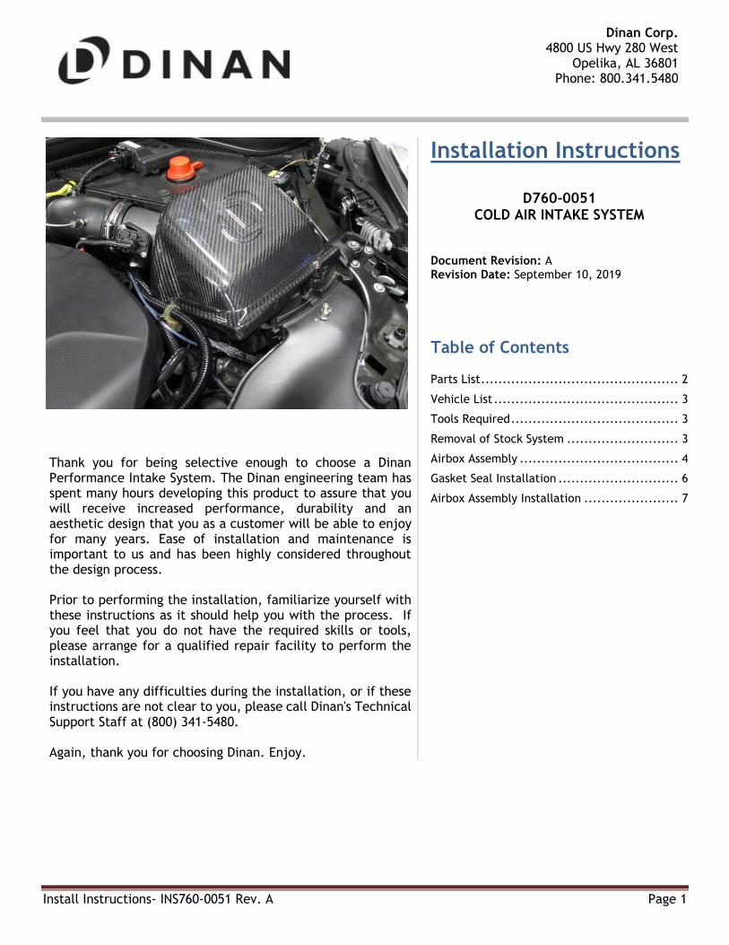
D760-0051 COLD AIR INTAKE SYSTEM
Document Revision: A Revision Date: September 10, 2019
Table of Contents Parts List .............................................. 2
Vehicle List ........................................... 3
Tools Required ....................................... 3
Removal of Stock System .......................... 3
Airbox Assembly ..................................... 4
Gasket Seal Installation ............................ 6
Airbox Assembly Installation ...................... 7
Thank you for being selective enough to choose a Dinan Performance Intake System. The Dinan engineering team has spent many hours developing this product to assure that you will receive increased performance, durability and an aesthetic design that you as a customer will be able to enjoy for many years. Ease of installation and maintenance is important to us and has been highly considered throughout the design process. Prior to performing the installation, familiarize yourself with these instructions as it should help you with the process. If you feel that you do not have the required skills or tools, please arrange for a qualified repair facility to perform the installation. If you have any difficulties during the installation, or if these instructions are not clear to you, please call Dinan's Technical Support Staff at (800) 341-5480. Again, thank you for choosing Dinan. Enjoy.

Install Instructions
Install Instructions: INS760-0051 Rev. A Page 2
Parts List **Model view may not represent actual look of part. For reference only**

Install Instructions
Install Instructions: INS760-0051 Rev. A Page 3
Vehicle List
2' F45 Active Tourer (11/2013 — 02/2018) 2' F45 Active Tourer LCI (05/2017 — 03/2019) 2' F46 Gran Tourer (07/2014 — 03/2018) X1 F48 (11/2014 — 04/2019) X2 F39 (10/2016 — 03/2019) MINI F56 (04/2013 — 03/2019) MINI F55 (09/2013 — 03/2019) MINI Clubman F54 (11/2014 — 03/2019) MINI Cabrio F57 (11/2014 — 03/2019) MINI Countryman F60 (11/2015 — 04/2019)
Tools Required
T20 and T25 Torx bit
2.5mm Allen Key
Flat head screwdriver
Removal of Stock System 1) (A) Loosen hose clamp. 2) (B) Remove grommet tab from upper airbox. This tab will not be re-installed on new airbox. 3) (C) Unplug and unscrew the air mass meter (2 screws) using a T20 Torx. These screws will be reused. 4) (D) Unscrew the mounting screws (3 screws) of the airbox lid using a T25 Torx. These screws will be
reused.

Install Instructions
Install Instructions: INS760-0051 Rev. A Page 4
5) Remove airbox lid and filter from system.
Airbox Assembly

Install Instructions
Install Instructions: INS760-0051 Rev. A Page 5
1) Ensure the air flow meter side opening is in the orientation shown below. Using the 4 washers and 4 screws,
hand tighten the mass air flow collar to the lid using the 2.5mm Allen key.
2) Install filter onto the air flow collar. The filter will fit over the collar and snap into place. The filter has
an opening offset that allows it to be oriented in a specific location. Ensure the filter nests properly inside
the air box.
3) Tighten the clamp.

Install Instructions
Install Instructions: INS760-0051 Rev. A Page 6
Gasket Seal Installation 1) Installation of this gasket will be mated to the inner lip of the lower installed airbox as shown below.
2) Using the supplied U-channel gasket, cut to length for each side of the airbox lid. Press fit on lip.

Install Instructions
Install Instructions: INS760-0051 Rev. A Page 7
Airbox Assembly Installation 1) Slide air meter collar into tube.
2) Seat airbox properly against the lower lid.
3) (A) Hand tighten the 3 screws (T25 Torx bit), attaching the Dinan lid to the lower lid. Do not over tighten.
4) (B) Re-insert air flow meter, plug it back in, and tighten screws (T20 Torx bit). Mounting holes only align
in one orientation.
5) (C) Tighten clamp.
6) INSTALLATION IS NOW COMPLETE. ENJOY!