simulation of thermal stresses in a brake disc - diva portal632213/fulltext01.pdf · ii.sequential...
TRANSCRIPT
Linkoping Studies in Science and Technology.Licentiate Thesis No. 1603
Simulation of Thermal Stresses ina Brake Disc
Asim Rashid
LIU–TEK–LIC–2013:37
Department of Management and Engineering, Division of MechanicsLinkoping University, SE–581 83, Linkoping, Sweden
Linkoping, May 2013
Cover:Temperature distribution on the disc surface after a brake application.
Printed by:LiU-Tryck, Linkoping, SwedenISBN 978-91-7519-575-9ISSN 0280-7971
Distributed by:Linkoping UniversityDepartment of Management and EngineeringSE–581 83, Linkoping, Sweden
c© 2013 Asim RashidThis document was prepared with LATEX, June 3, 2013
No part of this publication may be reproduced, stored in a retrieval system, or betransmitted, in any form or by any means, electronic, mechanical, photocopying,recording, or otherwise, without prior permission of the author.
Preface
First of all I would like to express my profound gratitude to my supervisor, NiclasStromberg, for his support and guidance. I am thankful to all the colleague at JTHfor a nice working environment. A special thanks to my former colleague, MagnusHofwing, for providing the relevant data to the project. I would also like to thankMartin Tapankov for his helpful suggestions for solving Latex related issues andrecommending very useful softwares.
I am very grateful for the funding by Vinnova and Volvo 3P. I would also like toexpress my gratitude to the people at Volvo 3P especially Magnus Levinsson andPer Hasselberg for providing the relevant data and fruitful discussions. Anotherthanks to Erik Holmberg at Linkoping Universtiy for providing the Latex templatefor this thesis.
Finally, I would like to thank my family for their support and patience.
Asim Rashid
Jonkoping, 2013-05-20
iii

Abstract
In this thesis thermal stresses in a brake disc during a braking operation are sim-ulated. The simulations are performed by using a sequential approach where thetemperature history generated during a frictional heat analysis is used as an in-put for the stress analysis. The frictional heat analysis is based on the Eulerianmethod, which requires significantly lower computational time as compared to theLagrangian approach. The stress analysis is performed using a temperature depen-dent material model both with isotropic and kinematic hardening behaviors. Theresults predict the presence of residual tensile stresses in circumferential directionfor both hardening behaviors. These residual stresses may cause initiation of ra-dial cracks on the disc surface after a few braking cycles. For repeated brakingan approximately stable stress-strain loop is obtained already after the first cyclefor the linear kinematic hardening model. So, if the fatigue life data for the discmaterial is known, its fatigue life can be assessed. These results are in agreementwith experimental observations available in the literature.
The simulation results predict one hot band in the middle of the disc for a padwith no wear history. It is also shown that convex bending of the pad is the majorcause of the contact pressure concentration in middle of the pad which results inthe appearance of a hot band on the disc surface. The results also show that dueto wear of the pad, different distributions of temperature on the disc surface areobtained for each new brake cycle and after a few braking cycles, two hot bandsappear on the disc surface.
This sequential approach has proved tremendously cheap in terms of computa-tional time so it gives the freedom to perform multi-objective optimization studies.Preliminary results of such a study are also presented where the mass of the backplate, the brake energy and the maximum temperature generated on the disc sur-face during hard braking are optimized. The results indicate that a brake padwith lowest possible stiffness will result in an optimized solution with regards to allthree objectives. Another interesting result is the trend of decrease in maximumtemperature with an increase in back plate thickness.
Finally an overview of disc brakes and related phenomena is presented as a litera-ture review.
v

List of Papers
This thesis is based on the following five papers:
I. An Efficient Sequential Approach for Simulation of Thermal Stresses in DiscBrakes
II. Sequential Simulation of Thermal Stresses in Disc Brakes for Repeated Brak-ing
III. Thermomechanical Simulation of Wear and Hot Bands in a Disc Brake byadopting an Eulerian approach
IV. Multi-Objective Optimization of a Disc Brake System by using SPEA2 andRBFN
V. Overview of Disc Brakes and Related Phenomena - a literature review
Papers have been reformatted to fit the layout of the thesis.
vii

Contents
Preface iii
Abstract v
List of Papers vii
Contents ix
1 Introduction 11.1 Background . . . . . . . . . . . . . . . . . . . . . . . . . . . . . . . 11.2 Governing equations . . . . . . . . . . . . . . . . . . . . . . . . . . 4
1.2.1 Heat transfer analysis . . . . . . . . . . . . . . . . . . . . . . 41.2.2 Stress analysis . . . . . . . . . . . . . . . . . . . . . . . . . . 5
1.3 Material model . . . . . . . . . . . . . . . . . . . . . . . . . . . . . 81.4 Residual stresses: a simple example . . . . . . . . . . . . . . . . . . 91.5 Results . . . . . . . . . . . . . . . . . . . . . . . . . . . . . . . . . . 11
2 Review of included papers 19
Bibliography 23
Paper I 27
Paper II 49
Paper III 71
Paper IV 89
Paper V 109
ix

Introduction1
1.1 Background
Disc brakes are an important component of a vehicle retardation system. Theyare used to stop or adjust the speed of a vehicle with changing road and trafficconditions. During braking, a set of pads is pressed against a rotating disc and,due to friction, heat is generated at the disc-pad interface, which causes the discsurface temperature to rise in a short period of time. This heat ultimately transfersto the vehicle and the environment, and the disc cools down.
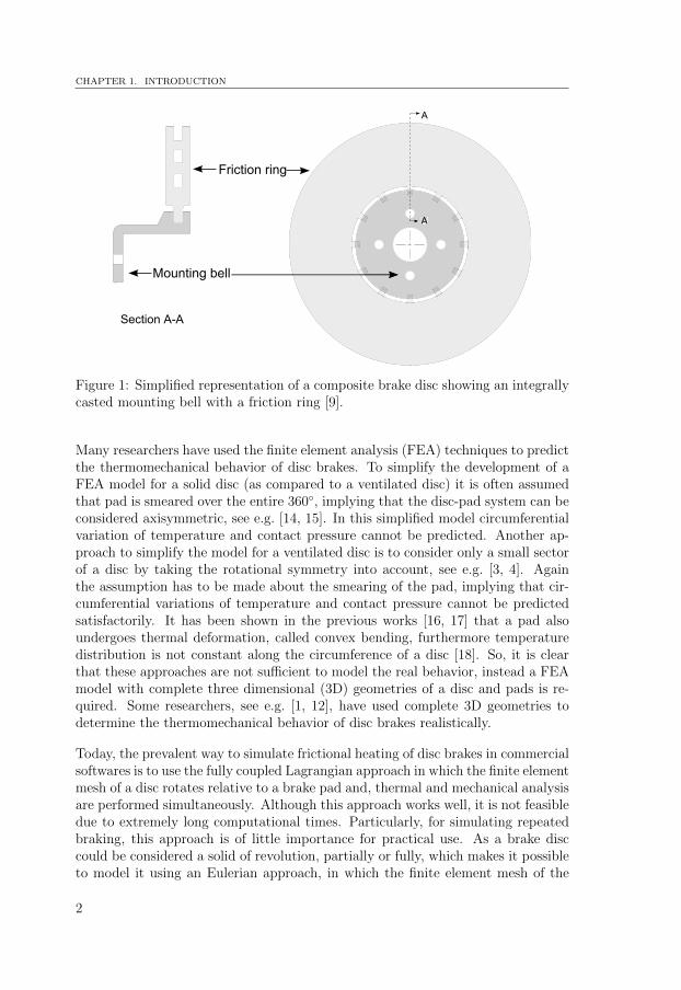
As a result of higher temperatures, in addition to local changes of the contactsurfaces, there are global deformations occurring in the disc and the pad. Due todifferent geometries of discs, each disc has different geometrical constraints to thethermal expansion. So the deformations can appear in different forms in differentdiscs. Some of the most commonly observed thermal deformations are coning andbuckling [1, 2, 3, 4, 5]. Such geometrical deviations could be avoided or reducedif thermal loading and disc geometry are symmetric about the midplane of thedisc [6, 7], and the friction ring is decoupled from the mounting bell so that ithas relatively more freedom of expansion in radial direction [8]. This is usuallyintended to achieve by using a so-called composite brake disc in which mountingbell and friction ring are separated from each other. Such a composite brake discis shown in figure 1.
In addition to these deformations, macrocracks might also appear on a disc surfacein the radial direction after some brake cycles, affecting the performance and life ofa brake disc [10, 11]. It has been shown in many previous works, e.g. [4, 12, 13], thatduring hard braking, high compressive stresses are generated in the circumferentialdirection on the disc surface which cause plastic yielding. But when the disccools down, these compressive stresses transform to tensile stresses. For repeatedbraking when this kind of stress-strain history is repeated, stress cycles with highamplitudes are developed which might generate low cycle fatigue cracks after afew braking cycles. Dufrenoy and Weichert [4], confirmed the existence of residualtensile stresses on the disc surface by measuring with the hole drilling strain gagemethod. In the present work investigation of the stresses which cause these crackson a disc surface, by using finite element simulations, is a major focus.
1
CHAPTER 1. INTRODUCTION
Mounting bell
Friction ring
A
A
Section A-A
A
Figure 1: Simplified representation of a composite brake disc showing an integrallycasted mounting bell with a friction ring [9].
Many researchers have used the finite element analysis (FEA) techniques to predictthe thermomechanical behavior of disc brakes. To simplify the development of aFEA model for a solid disc (as compared to a ventilated disc) it is often assumedthat pad is smeared over the entire 360◦, implying that the disc-pad system can beconsidered axisymmetric, see e.g. [14, 15]. In this simplified model circumferentialvariation of temperature and contact pressure cannot be predicted. Another ap-proach to simplify the model for a ventilated disc is to consider only a small sectorof a disc by taking the rotational symmetry into account, see e.g. [3, 4]. Againthe assumption has to be made about the smearing of the pad, implying that cir-cumferential variations of temperature and contact pressure cannot be predictedsatisfactorily. It has been shown in the previous works [16, 17] that a pad alsoundergoes thermal deformation, called convex bending, furthermore temperaturedistribution is not constant along the circumference of a disc [18]. So, it is clearthat these approaches are not sufficient to model the real behavior, instead a FEAmodel with complete three dimensional (3D) geometries of a disc and pads is re-quired. Some researchers, see e.g. [1, 12], have used complete 3D geometries todetermine the thermomechanical behavior of disc brakes realistically.
Today, the prevalent way to simulate frictional heating of disc brakes in commercialsoftwares is to use the fully coupled Lagrangian approach in which the finite elementmesh of a disc rotates relative to a brake pad and, thermal and mechanical analysisare performed simultaneously. Although this approach works well, it is not feasibledue to extremely long computational times. Particularly, for simulating repeatedbraking, this approach is of little importance for practical use. As a brake disccould be considered a solid of revolution, partially or fully, which makes it possibleto model it using an Eulerian approach, in which the finite element mesh of the
2

1.1. BACKGROUND
x
y
Mesh
Material
Eulerian description
Lagrangian description
Figure 2: Schematic representation of the Eulerian and the Lagrangian approaches.
disc does not rotate relative to the brake pad but the material flows through themesh. This requires significantly lower computational time as compared to theLagrangian approach. Figure 2 shows schematically both the Eulerian and theLagrangian approaches.
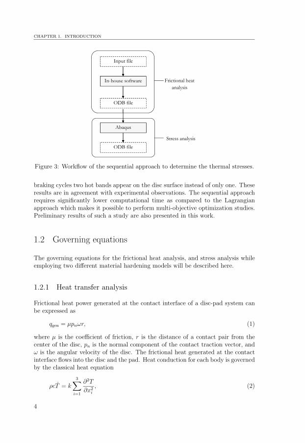
The simulations performed within this work are by using a sequential approachwhere temperature history from the frictional heat analysis is used as an input in acoupled stress analysis. The frictional heat analysis, based on the Eulerian method,is performed in an in-house software developed by Stromberg, which is describedin his earlier works [19, 20]. In this Eulerian approach the contact pressure is notconstant, but varies at each time step taking into account the thermomechanicaldeformations of the disc and the pad. This updated contact pressure informationis used to compute heat generation and flow to the contacting bodies at each timestep. In such manner, the nodal temperatures are updated accurately and theirhistory is recorded at each time step. Later stress analysis is performed in thecommercial software Abaqus, which uses thermal history from the frictional heatanalysis as an input. Figure 3 shows the workflow of this sequential approachschematically. Stresses due to the applied normal brake force, centrifugal forcesand deceleration forces are insignificant in comparison to the thermal stresses [21]so only thermal stresses are considered in this work.
The results show that during hard braking high compressive stresses are generatedon the disc surface in the circumferential direction which cause yielding. But whenthe disc cools down, these compressive stresses transform to tensile residual stresses.For repeated braking an approximately stable stress-strain loop is obtained. So, ifthe fatigue life data for the disc material is known, its fatigue life can be assessed.It is also shown that convex bending of the pad due to thermal deformations isthe major cause of contact pressure concentration and hence appearance of hotbands. The results show that when wear is considered, different distributions oftemperature on the disc surface are obtained for each new brake cycle. After a few
3
CHAPTER 1. INTRODUCTION
Input file
In-house software
ODB file
Abaqus
ODB file
Frictional heat
analysis
Stress analysis
Input file
In-house software
ODB file
Abaqus
ODB file
Figure 3: Workflow of the sequential approach to determine the thermal stresses.
braking cycles two hot bands appear on the disc surface instead of only one. Theseresults are in agreement with experimental observations. The sequential approachrequires significantly lower computational time as compared to the Lagrangianapproach which makes it possible to perform multi-objective optimization studies.Preliminary results of such a study are also presented in this work.
1.2 Governing equations
The governing equations for the frictional heat analysis, and stress analysis whileemploying two different material hardening models will be described here.
1.2.1 Heat transfer analysis
Frictional heat power generated at the contact interface of a disc-pad system canbe expressed as
qgen = µpnωr, (1)
where µ is the coefficient of friction, r is the distance of a contact pair from thecenter of the disc, pn is the normal component of the contact traction vector, andω is the angular velocity of the disc. The frictional heat generated at the contactinterface flows into the disc and the pad. Heat conduction for each body is governedby the classical heat equation
ρcT = k3∑
i=1
∂2T
∂x2i
, (2)
4
1.2. GOVERNING EQUATIONS
where ρ is the density, c is the specific heat capacity and k is the thermal conduc-tivity.
1.2.2 Stress analysis
Stress-strain relations used to describe deformation of a material are different forthe elastic and plastic domain. Consequently, it is important to know if the stressstate is in the elastic or plastic domain. For this purpose a yield criterion is used tosuggest the limit of elasticity and the initiation of yielding in a material under anycombination of stresses. There are several yield criterion used in practice. Someof these are: the maximum shear stress criterion, the maximum principal stresscriterion and the von Mises stress criterion. These criteria could be expressed interms of material constants obtained from different physical tests e.g. a shear ora uniaxial tensile test. In this work these material parameters are obtained byconsidering uniaxial tests at different temperatures.
According to the von Mises stress criterion, yielding depends on the deviatoricstress and not the hydrostatic stress. It is expressed as
√3J2 − σy = 0 for plastic deformation
√3J2 − σy < 0 for elastic deformation
(3)
where σy is the stress at yield in a uniaxial test and J2 is the second invariant ofthe deviatoric stress, i.e.
J2 =1
2s : s, (4)
where s is the deviatoric stress, given by
s = σ − tr(σ)
3I. (5)
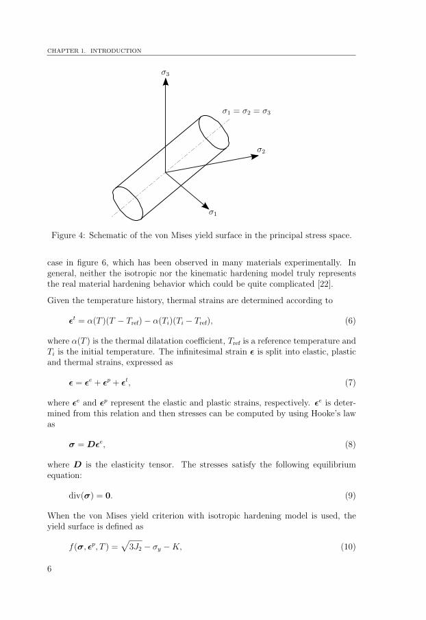
The von Mises yield criterion appears as a cylindrical surface in the principal stressspace as shown in figure 4. A loading case where stresses lie inside this surface issaid to be an elastic loading. The yield surface can be described as a boundarybetween elastic and plastic deformation regions.
During plastic deformations, subsequent yield surface can translate, expand ordistort in the stress space [22]. Two models are frequently used to describe thehardening behavior of a material due to plastic deformations: isotropic harden-ing and kinematic hardening. Isotropic hardening assumes that the yield surfaceexpands uniformly as shown in figure 5a. Kinematic hardening assumes that theyield surface translates in the stress space as shown in figure 5b. Pure isotropichardening cannot predict the Bauschinger effect, as shown for a uniaxial loading
5
CHAPTER 1. INTRODUCTION
σ3
σ1 = σ2 = σ3
σ1
σ2
Figure 4: Schematic of the von Mises yield surface in the principal stress space.
case in figure 6, which has been observed in many materials experimentally. Ingeneral, neither the isotropic nor the kinematic hardening model truly representsthe real material hardening behavior which could be quite complicated [22].
Given the temperature history, thermal strains are determined according to
εt = α(T )(T − Tref)− α(Ti)(Ti − Tref), (6)
where α(T ) is the thermal dilatation coefficient, Tref is a reference temperature andTi is the initial temperature. The infinitesimal strain ε is split into elastic, plasticand thermal strains, expressed as
ε = εe + εp + εt, (7)
where εe and εp represent the elastic and plastic strains, respectively. εe is deter-mined from this relation and then stresses can be computed by using Hooke’s lawas
σ = Dεe, (8)
where D is the elasticity tensor. The stresses satisfy the following equilibriumequation:
div(σ) = 0. (9)
When the von Mises yield criterion with isotropic hardening model is used, theyield surface is defined as
f(σ, εp, T ) =√
3J2 − σy −K, (10)
6

1.2. GOVERNING EQUATIONS
σ3
σ1 σ2
(a) Isotropic hardening
σ3
σ1 σ2
(b) Kinematic hardening
Figure 5: Evolution of the von Mises yield surface with isotropic and kinematichardening. Solid line represents initial yield surface and dashed line representssubsequent yield surface.
σy
σs
2σs
2σy
kinematic
isotropic
σ
ε
Figure 6: Uniaxial stress-strain curves for isotropic and kinematic hardening.
7
CHAPTER 1. INTRODUCTION
where σy = σy(T ) is the uniaxial yield strength and K = K(εpeff, T ) is the hardeningparameter. The effective plastic strain εpeff is expressed as
εpeff =
t∫
0
√2εp : εp
3dt. (11)
The plastic strain εp is governed by the following associative law
εp = λ3s
2√
3J2
, (12)
where λ is the plastic multiplier, which is determined by the Karush-Kuhn-Tuckerconditions:
λ ≥ 0, f ≤ 0, λf = 0. (13)
When the von Mises yield criterion with kinematic hardening model is used, theyield surface is defined as
f(η, T ) =
√3
2η : η − σy, (14)
where
η = s−α (15)
and α is the back-stress tensor. The evolution of the back-stress is governed byZiegler’s rule, which can be written as
α =k
σy(s−α)εpeff, (16)
where k = k(T ) is the kinematic hardening modulus and the plastic strain εp isgoverned by the following associative law:
εp = λ3
2
η√32η : η
. (17)
1.3 Material model
To predict the thermomechanical behavior of a component realistically, it is im-portant to have a material model which represents its characteristics sufficientlyaccurately. During the frictional heat analysis, temperature independent materialdata has been used for all the components. For more realistic results, temperaturedependent material data should be used. During stress analysis only the brakedisc is considered. The brake disc is casted in a grey iron alloy. The material
8
1.4. RESIDUAL STRESSES: A SIMPLE EXAMPLE
model used in the present work was developed in an earlier work [23] in orderto simulate residual stresses in castings from solidification and is now utilized forthermomechanical stress analysis.
Most of the material parameters required to develop this model were obtained frommeasurements. Young’s modulus, the yield strength and hardening behavior wereobtained from tensile tests performed at 20◦C, 200◦C, 400◦C, 600◦C and 800◦C.The data was assumed or collected from literature for temperatures above 800◦C.This material data is used to build a temperature dependent material model withnonlinear hardening which is described in detail in Paper I. The same data isused to build a temperature dependent material model with linear hardening byconnecting the first and last point of the hardening curve with a straight line. Thislinear hardening model is described in detail in Paper II.
The grey iron alloy shows different yield properties in tension and compression [7].In the present work, it is assumed that the material has the same behavior bothin tension and compression. Although this assumption is unrealistic, it is not thepurpose of this work to develop a better material model. Moreover, in this work,the von Mises yield criterion is used both in tension and compression.
In [7] a material model which employs the maximum principal stress yield criterionin tension and von Mises yield criterion in compression was used. Another materialmodel which considers different yield behaviors in tension and compression, andemploys the von Mises yield criterion both in tension and compression, is reportedin [7] and [3]. In the latter model, numerical results were much closer to themeasured experimental data.
1.4 Residual stresses: a simple example
Sometimes, permanent stresses develop in a component even after the externalcause, e.g. heat gradient or force, has been removed. In the case of thermal stresses,if they are sufficiently large to cause yielding in a component, then these stressesmay develop to residual stresses when the component cools down. Residual stressesmay affect the behavior and life of such a component. In order to describe thiskind of phenomenon, finite element analysis of a bar subjected to a temperatureload will be described and presence of residual stresses after the cooling of the barwill be shown.
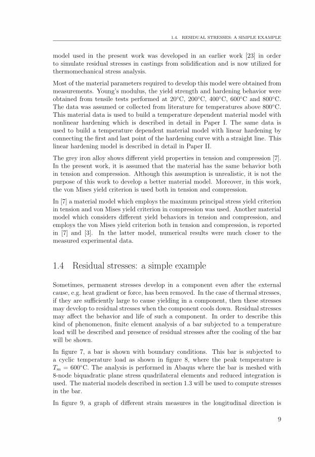
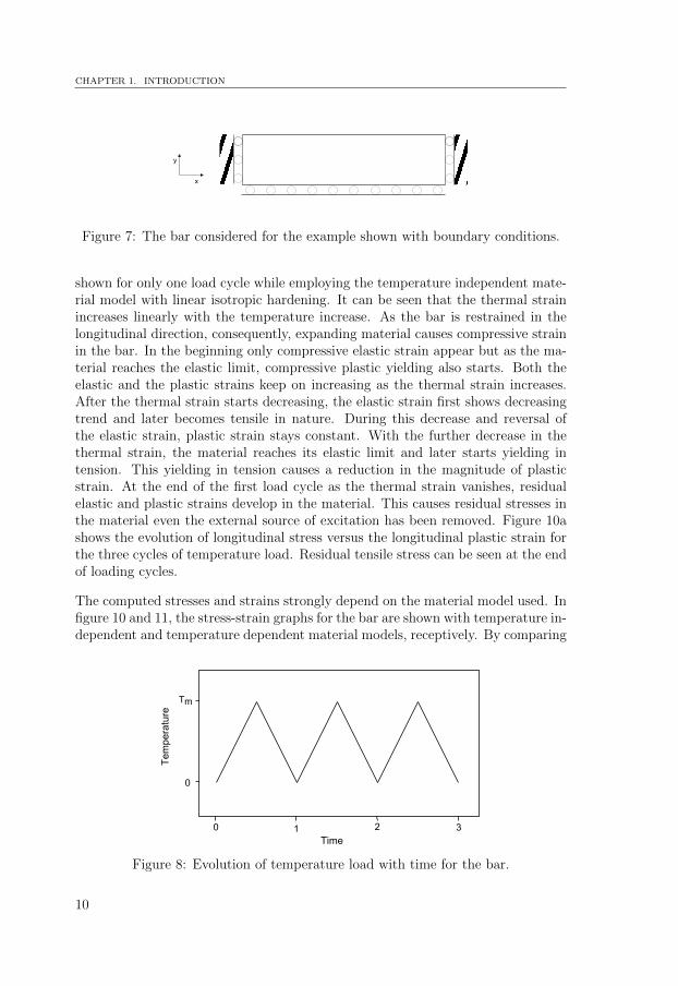
In figure 7, a bar is shown with boundary conditions. This bar is subjected toa cyclic temperature load as shown in figure 8, where the peak temperature isTm = 600◦C. The analysis is performed in Abaqus where the bar is meshed with8-node biquadratic plane stress quadrilateral elements and reduced integration isused. The material models described in section 1.3 will be used to compute stressesin the bar.
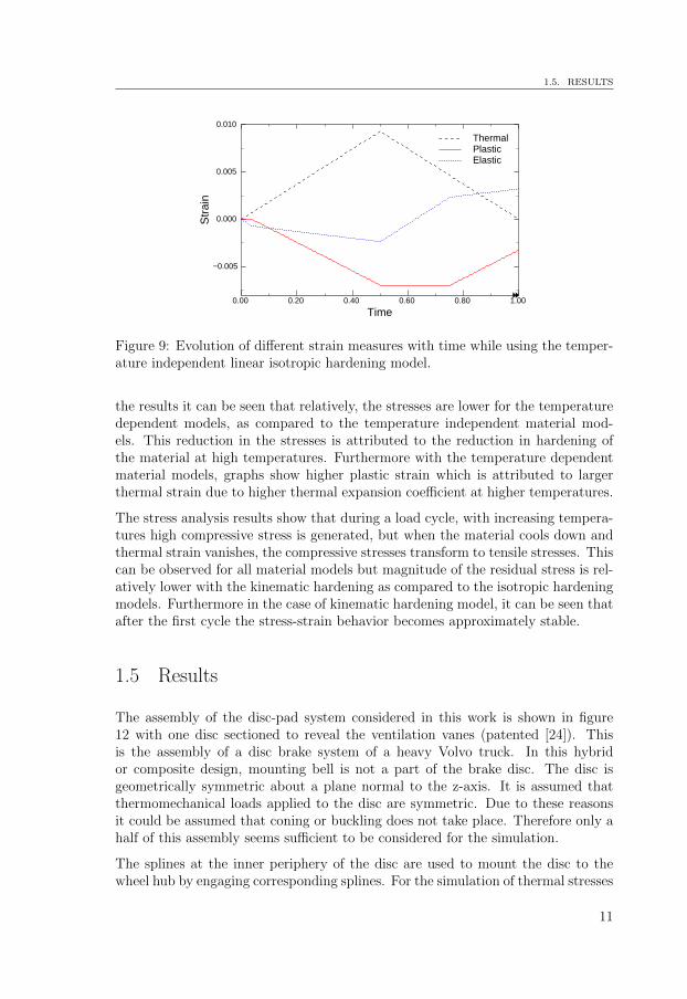
In figure 9, a graph of different strain measures in the longitudinal direction is
9
CHAPTER 1. INTRODUCTION
x
y
Figure 7: The bar considered for the example shown with boundary conditions.
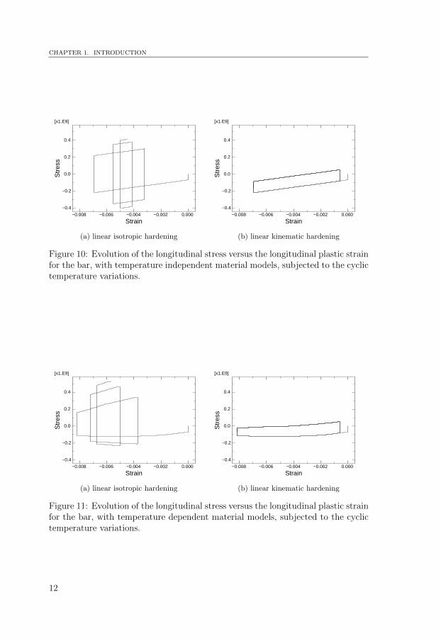
shown for only one load cycle while employing the temperature independent mate-rial model with linear isotropic hardening. It can be seen that the thermal strainincreases linearly with the temperature increase. As the bar is restrained in thelongitudinal direction, consequently, expanding material causes compressive strainin the bar. In the beginning only compressive elastic strain appear but as the ma-terial reaches the elastic limit, compressive plastic yielding also starts. Both theelastic and the plastic strains keep on increasing as the thermal strain increases.After the thermal strain starts decreasing, the elastic strain first shows decreasingtrend and later becomes tensile in nature. During this decrease and reversal ofthe elastic strain, plastic strain stays constant. With the further decrease in thethermal strain, the material reaches its elastic limit and later starts yielding intension. This yielding in tension causes a reduction in the magnitude of plasticstrain. At the end of the first load cycle as the thermal strain vanishes, residualelastic and plastic strains develop in the material. This causes residual stresses inthe material even the external source of excitation has been removed. Figure 10ashows the evolution of longitudinal stress versus the longitudinal plastic strain forthe three cycles of temperature load. Residual tensile stress can be seen at the endof loading cycles.
The computed stresses and strains strongly depend on the material model used. Infigure 10 and 11, the stress-strain graphs for the bar are shown with temperature in-dependent and temperature dependent material models, receptively. By comparing
0 1 2 3
Temperature
Tm
Time
0
Figure 8: Evolution of temperature load with time for the bar.
10
1.5. RESULTS
Time0.00 0.20 0.40 0.60 0.80 1.00
Str
ain
−0.005
0.000
0.005
0.010
ThermalPlasticElastic
Figure 9: Evolution of different strain measures with time while using the temper-ature independent linear isotropic hardening model.
the results it can be seen that relatively, the stresses are lower for the temperaturedependent models, as compared to the temperature independent material mod-els. This reduction in the stresses is attributed to the reduction in hardening ofthe material at high temperatures. Furthermore with the temperature dependentmaterial models, graphs show higher plastic strain which is attributed to largerthermal strain due to higher thermal expansion coefficient at higher temperatures.
The stress analysis results show that during a load cycle, with increasing tempera-tures high compressive stress is generated, but when the material cools down andthermal strain vanishes, the compressive stresses transform to tensile stresses. Thiscan be observed for all material models but magnitude of the residual stress is rel-atively lower with the kinematic hardening as compared to the isotropic hardeningmodels. Furthermore in the case of kinematic hardening model, it can be seen thatafter the first cycle the stress-strain behavior becomes approximately stable.
1.5 Results
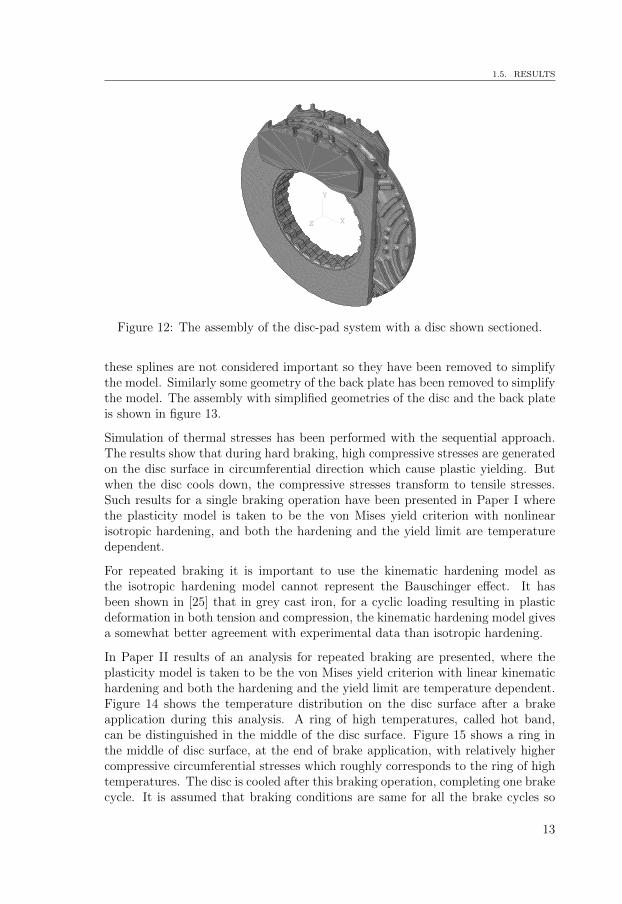
The assembly of the disc-pad system considered in this work is shown in figure12 with one disc sectioned to reveal the ventilation vanes (patented [24]). Thisis the assembly of a disc brake system of a heavy Volvo truck. In this hybridor composite design, mounting bell is not a part of the brake disc. The disc isgeometrically symmetric about a plane normal to the z-axis. It is assumed thatthermomechanical loads applied to the disc are symmetric. Due to these reasonsit could be assumed that coning or buckling does not take place. Therefore only ahalf of this assembly seems sufficient to be considered for the simulation.
The splines at the inner periphery of the disc are used to mount the disc to thewheel hub by engaging corresponding splines. For the simulation of thermal stresses
11
CHAPTER 1. INTRODUCTION
Strain−0.008 −0.006 −0.004 −0.002 0.000
Str
ess
−0.4
−0.2
0.0
0.2
0.4
[x1.E9]
(a) linear isotropic hardening
Strain−0.008 −0.006 −0.004 −0.002 0.000
Str
ess
−0.4
−0.2
0.0
0.2
0.4
[x1.E9]
(b) linear kinematic hardening
Figure 10: Evolution of the longitudinal stress versus the longitudinal plastic strainfor the bar, with temperature independent material models, subjected to the cyclictemperature variations.
Strain−0.008 −0.006 −0.004 −0.002 0.000
Str
ess
−0.4
−0.2
0.0
0.2
0.4
[x1.E9]
(a) linear isotropic hardening
Strain−0.008 −0.006 −0.004 −0.002 0.000
Str
ess
−0.4
−0.2
0.0
0.2
0.4
[x1.E9]
(b) linear kinematic hardening
Figure 11: Evolution of the longitudinal stress versus the longitudinal plastic strainfor the bar, with temperature dependent material models, subjected to the cyclictemperature variations.
12
1.5. RESULTS
Z
Y
X
Figure 12: The assembly of the disc-pad system with a disc shown sectioned.
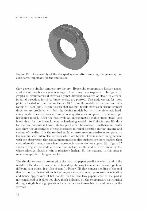
these splines are not considered important so they have been removed to simplifythe model. Similarly some geometry of the back plate has been removed to simplifythe model. The assembly with simplified geometries of the disc and the back plateis shown in figure 13.
Simulation of thermal stresses has been performed with the sequential approach.The results show that during hard braking, high compressive stresses are generatedon the disc surface in circumferential direction which cause plastic yielding. Butwhen the disc cools down, the compressive stresses transform to tensile stresses.Such results for a single braking operation have been presented in Paper I wherethe plasticity model is taken to be the von Mises yield criterion with nonlinearisotropic hardening, and both the hardening and the yield limit are temperaturedependent.
For repeated braking it is important to use the kinematic hardening model asthe isotropic hardening model cannot represent the Bauschinger effect. It hasbeen shown in [25] that in grey cast iron, for a cyclic loading resulting in plasticdeformation in both tension and compression, the kinematic hardening model givesa somewhat better agreement with experimental data than isotropic hardening.
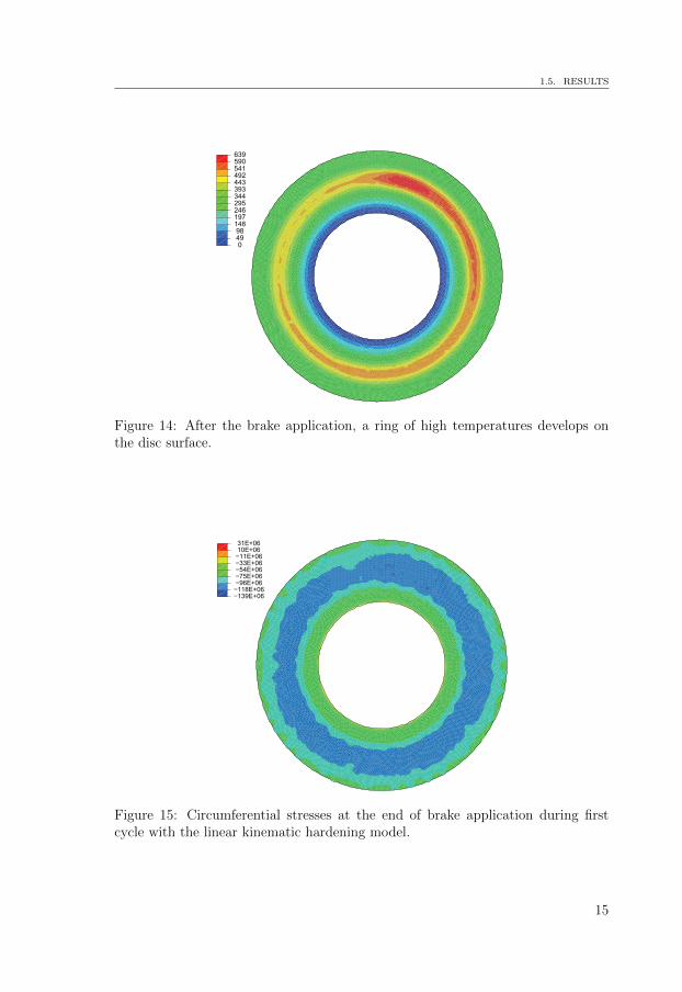
In Paper II results of an analysis for repeated braking are presented, where theplasticity model is taken to be the von Mises yield criterion with linear kinematichardening and both the hardening and the yield limit are temperature dependent.Figure 14 shows the temperature distribution on the disc surface after a brakeapplication during this analysis. A ring of high temperatures, called hot band,can be distinguished in the middle of the disc surface. Figure 15 shows a ring inthe middle of disc surface, at the end of brake application, with relatively highercompressive circumferential stresses which roughly corresponds to the ring of hightemperatures. The disc is cooled after this braking operation, completing one brakecycle. It is assumed that braking conditions are same for all the brake cycles so
13
CHAPTER 1. INTRODUCTION
Z
Y
X
Figure 13: The assembly of the disc-pad system after removing the geometry notconsidered important for the simulation.
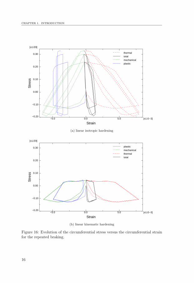
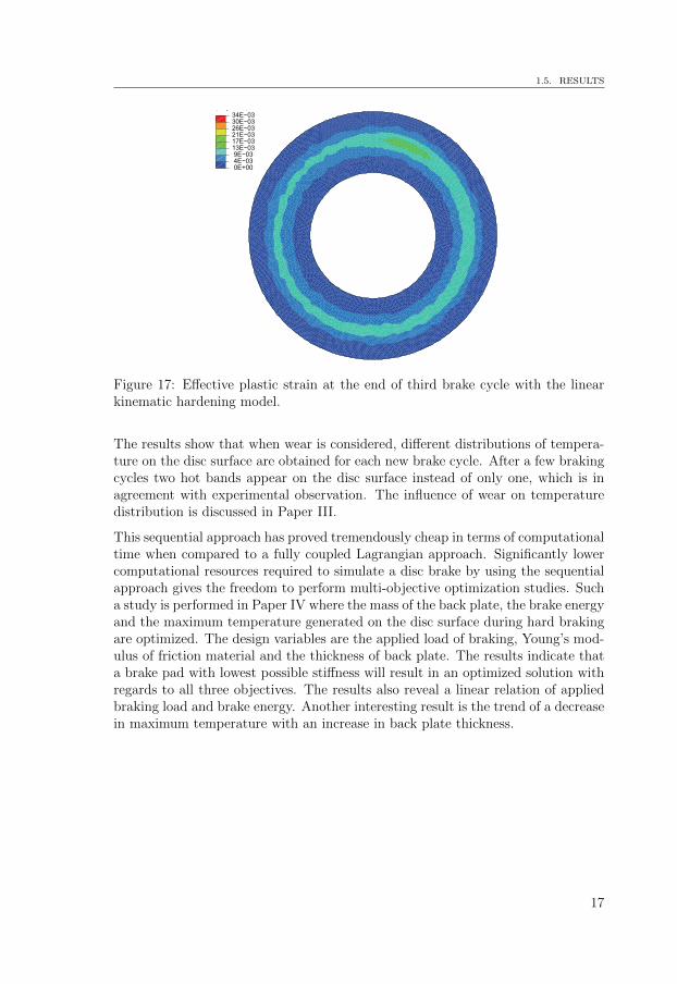
they generate similar temperature history. Hence the temperature history gener-ated during one brake cycle is merged three times in a sequence. In figure 16,graphs of circumferential stresses against different measures of strain in circum-ferential direction, for three brake cycles, are plotted. The node chosen for theseplots is located on the disc surface at 180◦ from the middle of the pad and at aradius of 163.9 [mm]. It can be seen that residual tensile stresses in circumferentialdirection are predicted with both hardening models but with the kinematic hard-ening model these stresses are lower in magnitude as compared to the isotropichardening model. After the first cycle an approximately stable stress-strain loopis obtained for the linear kinematic hardening model. So if the fatigue life datafor the disc material is known, its fatigue life can be assessed. Furthermore resultsalso show the appearance of tensile stresses in radial direction during braking andcooling of the disc. But the residual radial stresses are compressive as compared tothe residual circumferential stresses which are tensile. This is indeed in agreementwith the observation that radial microcracks on disc surfaces are more marked thancircumferential ones, even when macroscopic cracks do not appear [4]. Figure 17shows a ring in the middle of the disc surface, at the end of three brake cycles,where effective plastic strain is relatively higher. So the material in this area ismost susceptible to fatigue cracks.
The simulation results presented in the first two papers predict one hot band in themiddle of the disc. It has been explained by showing the contact pressure plots atdifferent time steps. It is also shown (in Paper III) that convex bending of the paddue to thermal deformations is the major cause of contact pressure concentrationand hence appearance of hot bands. In the first two papers wear of the pad isnot considered as it does not show much influence on the temperature distributionduring a single braking operation for a pad without wear history and hence on thestresses.
14
1.5. RESULTS
NT11
0
49
98
148
197
246
295
344
393
443
492
541
590
639
Figure 14: After the brake application, a ring of high temperatures develops onthe disc surface.
( g )
139E+06118E+06
96E+06 75E+06 54E+06 33E+06 11E+06 10E+06 31E+06
Figure 15: Circumferential stresses at the end of brake application during firstcycle with the linear kinematic hardening model.
15
CHAPTER 1. INTRODUCTION
Strain−5.0 0.0 5.0 [x1.E−3]
Str
ess
−0.20
−0.10
0.00
0.10
0.20
0.30
[x1.E9]
thermaltotalmechanicalplastic
(a) linear isotropic hardening
Strain−5.0 0.0 5.0 [x1.E−3]
Str
ess
−0.20
−0.10
0.00
0.10
0.20
0.30
[x1.E9]
plasticmechanicalthermaltotal
(b) linear kinematic hardening
Figure 16: Evolution of the circumferential stress versus the circumferential strainfor the repeated braking.
16
1.5. RESULTS
( g )
0E+00 4E 03 9E 0313E 0317E 0321E 0326E 0330E 0334E 03
Figure 17: Effective plastic strain at the end of third brake cycle with the linearkinematic hardening model.
The results show that when wear is considered, different distributions of tempera-ture on the disc surface are obtained for each new brake cycle. After a few brakingcycles two hot bands appear on the disc surface instead of only one, which is inagreement with experimental observation. The influence of wear on temperaturedistribution is discussed in Paper III.
This sequential approach has proved tremendously cheap in terms of computationaltime when compared to a fully coupled Lagrangian approach. Significantly lowercomputational resources required to simulate a disc brake by using the sequentialapproach gives the freedom to perform multi-objective optimization studies. Sucha study is performed in Paper IV where the mass of the back plate, the brake energyand the maximum temperature generated on the disc surface during hard brakingare optimized. The design variables are the applied load of braking, Young’s mod-ulus of friction material and the thickness of back plate. The results indicate thata brake pad with lowest possible stiffness will result in an optimized solution withregards to all three objectives. The results also reveal a linear relation of appliedbraking load and brake energy. Another interesting result is the trend of a decreasein maximum temperature with an increase in back plate thickness.
17

Review of included papers2
Paper I
In this paper results of a simulation of stresses in a brake disc for a single brakingoperation are presented. The plasticity model is taken to be the von Mises yieldcriterion with nonlinear isotropic hardening, where both the hardening and theyield limit are temperature dependent.
Paper II
In this paper results of a simulation of thermal stresses in a brake disc for repeatedbraking are presented. The plasticity model is taken to be the von Mises yieldcriterion with linear kinematic hardening, where both the hardening and the yieldlimit are temperature dependent.
Paper III
In this paper the influence of the wear history of a pad on the temperature dis-tribution on a disc surface is presented. It is also shown that convex bending ofa pad assembly as a result of thermal deformations is a significant factor towardsthe concentration of contact pressure in the middle of a pad.
Paper IV
In this paper results for a multi-objective optimization of a disc brake system arepresented. The mass of the back plate of the brake pad, the brake energy and themaximum temperature generated in the disc during hard braking are optimized.The design variables are the applied load of braking, Young’s modulus of frictionmaterial and the thickness of the back plate.
19

CHAPTER 2. REVIEW OF INCLUDED PAPERS
Paper V
In this paper a literature review of disc brakes and related phenomena is presented.A detailed description of different geometries and materials for the components of abrake assembly is given. The evolution of tribological interface of disc-pad system isalso covered in detail here. Different operational problems such as fade, geometricaldeviations and noise are also discussed.
20
Bibliography
[1] T.K. Kao, J.W. Richmond, and A. Douarre. Brake disc hot spotting and ther-mal judder: an experimental and finite element study. International Journalof Vehicle Design, 23(3):276–296, 2000.
[2] D. Eggleston. An investigation into frictional surface interactions and theireffect on brake judder. PhD thesis, Sheffield Hallam University, 2000.
[3] S. Koetniyom, P.C. Brooks, and D.C. Barton. The development of a materialmodel for cast iron that can be used for brake system analysis. Proceedingsof the Institution of Mechanical Engineers, Part D: Journal of AutomobileEngineering, 216(5):349–362, 2002.
[4] P. Dufrenoy and D. Weichert. A thermomechanical model for the analysis ofdisc brake fracture mechanisms. Journal of Thermal Stresses, 26(8):815–828,2003.
[5] S. Panier, P. Dufrenoy, and D. Weichert. An experimental investigation of hotspots in railway disc brakes. Wear, 256(7-8):764–773, 2004.
[6] S. Panier, P. Dufrenoy, J.F. Brunel, and D. Weichert. Progressive wavinessdistortion: A new approach of hot spotting in disc brakes. Journal of ThermalStresses, 28(1):47–62, 2005.
[7] S. Koetniyom. Thermal Stress Analysis of Automotive Disc Brakes. PhDthesis, University of Leeds, 2000.
[8] T. Deichmann and H. Lathwesen. Sheet cast disc-brake disc innovationthrough functional integration. Proceedings of the Eurobrake, 16-18 April,Dresden, Germany, 2012.
[9] A. Giorgetti. Disc for a disc brake for vehicles in general and for high-performance cars in particular, November 28 2000. US Patent 6,152,270.
[10] D.J. Kim, Y.M. Lee, J.S. Park, and C.S. Seok. Thermal stress analysis for adisk brake of railway vehicles with consideration of the pressure distributionon a frictional surface. Materials Science and Engineering A, 483-484(1-2C):456–459, 2008.
[11] F. Bagnoli, F. Dolce, and M. Bernabei. Thermal fatigue cracks of fire fighting
21
BIBLIOGRAPHY
vehicles gray iron brake discs. Engineering Failure Analysis, 16(1):152–163,2009.
[12] C. Gao, J.M. Huang, X.Z. Lin, and X.S.C. Tang. Stress analysis of thermalfatigue fracture of brake disks based on thermomechanical coupling. Journalof Tribology, 129(3):536–543, 2007.
[13] T.J. Mackin, S.C. Noe, K.J. Ball, B.C. Bedell, et al. Thermal cracking in discbrakes. Engineering Failure Analysis, 9(1):63–76, 2002.
[14] P. Dufrenoy and D. Weichert. Prediction of railway disc brake temperaturestaking the bearing surface variations into account. Proceedings of the Insti-tution of Mechanical Engineers, Part F: Journal of Rail and Rapid Transit,209(2):67–76, 1995.
[15] J. Choi and I. Lee. Finite element analysis of transient thermoelastic behaviorsin disk brakes. Wear, 257(1-2):47–58, 2004.
[16] K. Lee and J.R. Barber. An experimental investigation of frictionally-excitedthermoelastic instability in automotive disk brakes under a drag brake appli-cation. Journal of Tribology, 116(3):409–414, 1994.
[17] M. Eriksson, F. Bergman, and S. Jacobson. On the nature of tribologicalcontact in automotive brakes. Wear, 252(1-2):26–36, 2002.
[18] P. Dufrenoy. Two-/three-dimensional hybrid model of the thermomechanicalbehaviour of disc brakes. Proceedings of the Institution of Mechanical Engi-neers, Part F: Journal of Rail and Rapid Transit, 218(1):17–30, 2004.
[19] N. Stromberg. Development and implementation of an Eulerian aproach forefficient simulation of frictional heating in sliding contacts. In IV InternationalConference on Computational methods for Coupled Problems in Science andEngineering (ECCOMAS), Kos, Greece, 20-22 June 2011.
[20] N. Stromberg. An Eulerian approach for simulating frictional heating in disc-pad systems. European Journal of Mechanics - A/Solids, 30(5):673 – 683,2011.
[21] S. Medonos. Study of structural behaviour of ventilated brake disc. SAETechnical Paper 831316, 1983.
[22] A.S. Khan and S. Huang. Continuum Theory of Plasticity. Wiley-Interscience,1995.
[23] E. Gustafsson, M. Hofwing, and N. Stromberg. Residual stresses in a stresslattice–experiments and finite element simulations. Journal of Materials Pro-cessing Technology, 209(9):4320 – 4328, 2009.
[24] J. Hulten and I. Dagh. Brake disc for a vehicle disc brake, August 29 2006.US Patent 7,097,010.
22

BIBLIOGRAPHY
[25] B.L. Josefson, U. Stigh, and H.E. Hjelm. Nonlinear kinematic hardening modelfor elastoplastic deformations in grey cast iron. Journal of Engineering Mate-rials and Technology, Transactions of the ASME, 117(2):145–150, 1995.
23