simulation of the actions in silo and tanks with the ... · silo wall pressures (design values...
TRANSCRIPT

Simulation of the Actions in Silo and Tanks with the Smooth Particles Hydrodynamics Method
presented by
Arcangelo SCHENA - managerCIMES sarl360 rue Marc LefrancqLes Ateliers Numeriques59300 Valenciennes – FranceTel. : 0033 (0)327416271E-mail : [email protected]
http://www.cimesfrance.com
EHTC - 1 October 2008

CIMES has built up its reputation by capitalizing on its experience in handlinginnovative projects and dealing with technologie challenges (channel tunnel, high-speed trains, composites, etc .(...
It provides services for major industrial fields and companies with its know-how in advanced numerical simulation and the skills of specialists experienced in the use ofcutting-edge tools.
�SECTORS of ACTIVITY : Railway (passenger transport and freight), Industry, Aeronautic
�FEA softwares :Implicit analysis : ANSYS, NASTRAN, RADIOSS bulk and OPTISTRUCT
Explicit calculation : RADIOSS block and LS-DYNA
CFD calculation : ANSYS CFX
Pre and post processing : HYPERWORKS PRODUCTS
�FIELDS OF COMPETENCE :Linear and non-linear static analysis (plasticity, creep, ...)
Dynamic analysis : modal, crash, sloshing, ALE, SPH, explosion ...Fatigue analysis: mono and multiaxial loadsRandom vibrations (PSD)
Stationary and transient thermic analysis
� SOFTWARE DISTRIBUTION of the HYPERWORKS products since 2007

TGV3G new seat design by Christian Lacroix
Simulation of the behavior of a double seat in the event of crash – courtesy of COMPIN and SNCF

EXAMPLE 1
Prediction of loads in silos due to the stored material at rest condition

3-Dimensional modelling of granular material in silos and resulting loads at rest conditions
Common design practice vs. SPH method
The structural analysis of a cylindrical steel silo is carried out by firstly using the common practice approach based on the design values of the European standard EC1, and secondly by using the meshless numerical method SPH. The results predicted by both approach such as pressures on silo walls are
compared and discussed.

Objective and scope of the study
According to the most existing standards the silos wall loads are still based on the analytical slice model of Janssen (1895). This simplified model can only be used to estimate the wall pressures at rest conditions and symmetric cross-section.
To overcome these limitations and to allow for pressure variations during filling and discharge, it is a common design practice to multiply the uniform static pressures due to Janssen by empirical overpressure factors derived from experimental data.
But these practical rules are often too conservatives and lead to an uneconomical and not necessarily safe design of silos.
In order to improve the structural analysis of the silos an alternative approach must be used instead of the simplified design rules from standards. The interaction between the silo walls and the bulk solid as well as the nonlinear behaviour of the granular material must be considered.
The main purpose of this study is to analyse the capabilities of the SPH method to simulate the bulk solids behaviour and to predict the silo loads.
� Can the SPH method be a useful engineering tool to design silos ?

Silo geometry and parameters
Tested model :
- Cylindrical steel silo
- Conical hopper
- Centric outlet
- Wall thickness : 2 mm
- E = 210 GPa, ν = 0.3
- Steel grade S235
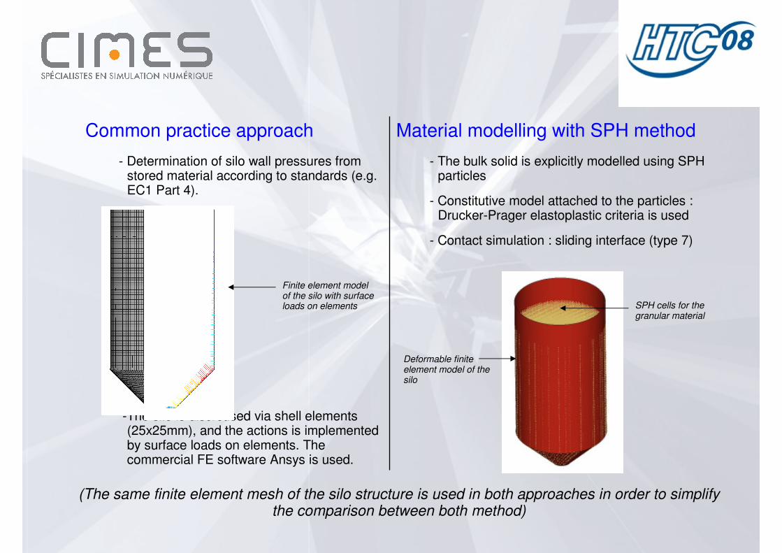
(The same finite element mesh of the silo structure is used in both approaches in order to simplify the comparison between both method)
Material modelling with SPH method
- The bulk solid is explicitly modelled using SPH particles
- Constitutive model attached to the particles : Drucker-Prager elastoplastic criteria is used
- Contact simulation : sliding interface (type 7)
Common practice approach
- Determination of silo wall pressures from stored material according to standards (e.g. EC1 Part 4).
-The silo is discretised via shell elements (25x25mm), and the actions is implemented by surface loads on elements. The commercial FE software Ansys is used.
Finite element model of the silo with surface loads on elements SPH cells for the
granular material
Deformable finite element model of the silo
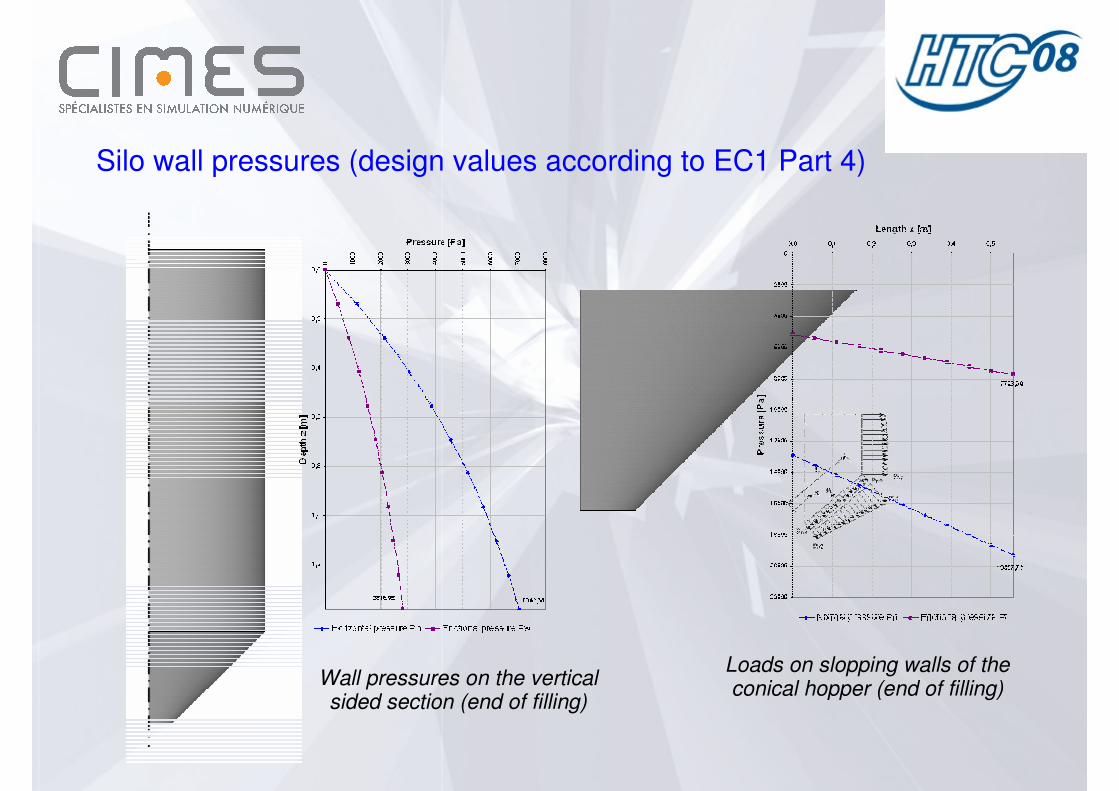
Silo wall pressures (design values according to EC1 Part 4)
Wall pressures on the vertical sided section (end of filling)
Loads on slopping walls of the conical hopper (end of filling)

Results : wall normal pressures comparison at rest condition
Wall normal pressure on the vertical sided section
Wall normal pressure on slopping walls of the hopper

Results : stresses comparison at rest condition
Contour plot of Equivalent Von Mises stresses
calculated by SPH method
Contour plot of Equivalent Von Mises stresses
calculated from design values
σmax=39.1 MPa
at the transition
σmax=37.7 MPa
at the transition

Results : contour plot of displacement within the material at end of filling

Conclusions
As a first stage of evaluation of the SPH method, only the resulting loads from the stored material at rest were studied. Based on the numerical results the following observations can be made :
Significant differences can be noted between the two approaches in the pattern of pressures and especially in the magnitude. For instance, the analytical value of the horizontal pressure given by EC standard is of 7 kPa at the transition, while the mean value obtained from the SPH method reaches approximately 12 kPa at the same location.
Globally, the values calculated using the SPH method are greater than expected. Indeed, the values of the EC standard are very conservative as experimental data and many numerical analyses have highlighted in recent journal publications.
The differences observed can probably be explained by the choice of the parameters of the constitutive law that has a great influence on the results, and in other hand by the deformability of the walls that modifies the pressure distribution.
These latest points must be part of further investigations. The logical progression of these analyses will be to used this method to simulate the complex behaviour of the bulk material during filling and discharge processes.
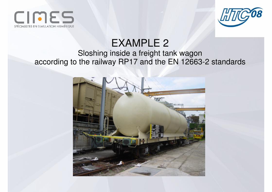
EXAMPLE 2Sloshing inside a freight tank wagon
according to the railway RP17 and the EN 12663-2 standards
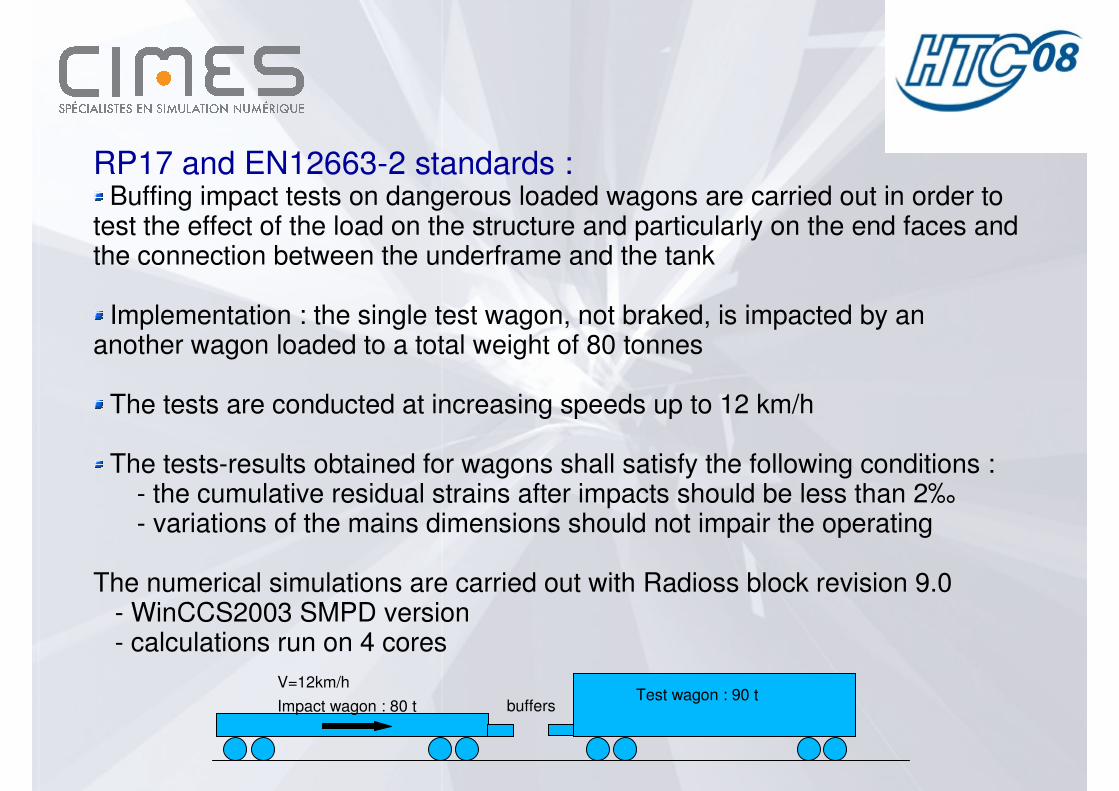
RP17 and EN12663-2 standards :Buffing impact tests on dangerous loaded wagons are carried out in order to
test the effect of the load on the structure and particularly on the end faces andthe connection between the underframe and the tank
Implementation : the single test wagon, not braked, is impacted by an another wagon loaded to a total weight of 80 tonnes
The tests are conducted at increasing speeds up to 12 km/h
The tests-results obtained for wagons shall satisfy the following conditions :- the cumulative residual strains after impacts should be less than 2‰- variations of the mains dimensions should not impair the operating
The numerical simulations are carried out with Radioss block revision 9.0- WinCCS2003 SMPD version- calculations run on 4 cores
V=12km/h
Impact wagon : 80 tTest wagon : 90 t
buffers
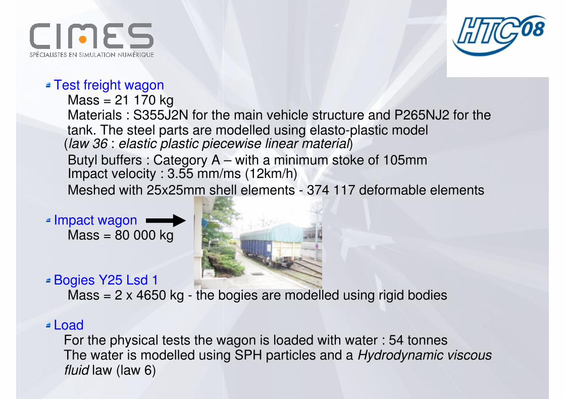
Test freight wagonMass = 21 170 kgMaterials : S355J2N for the main vehicle structure and P265NJ2 for thetank. The steel parts are modelled using elasto-plastic model(law 36 : elastic plastic piecewise linear material)
Butyl buffers : Category A – with a minimum stoke of 105mmImpact velocity : 3.55 mm/ms (12km/h)
Meshed with 25x25mm shell elements - 374 117 deformable elements
Impact wagonMass = 80 000 kg
Bogies Y25 Lsd 1Mass = 2 x 4650 kg - the bogies are modelled using rigid bodies
LoadFor the physical tests the wagon is loaded with water : 54 tonnesThe water is modelled using SPH particles and a Hydrodynamic viscousfluid law (law 6)
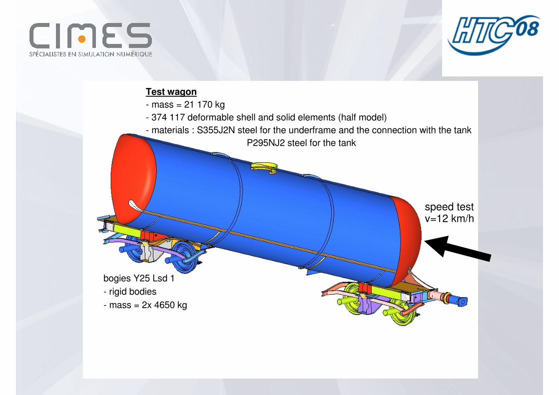
Tank wagon model for sloshing analysis
Test wagon
- mass = 21 170 kg
- 374 117 deformable shell and solid elements (half model)
- materials : S355J2N steel for the underframe and the connection with the tank
P295NJ2 steel for the tank
bogies Y25 Lsd 1
- rigid bodies
- mass = 2x 4650 kg
speed testv=12 km/h
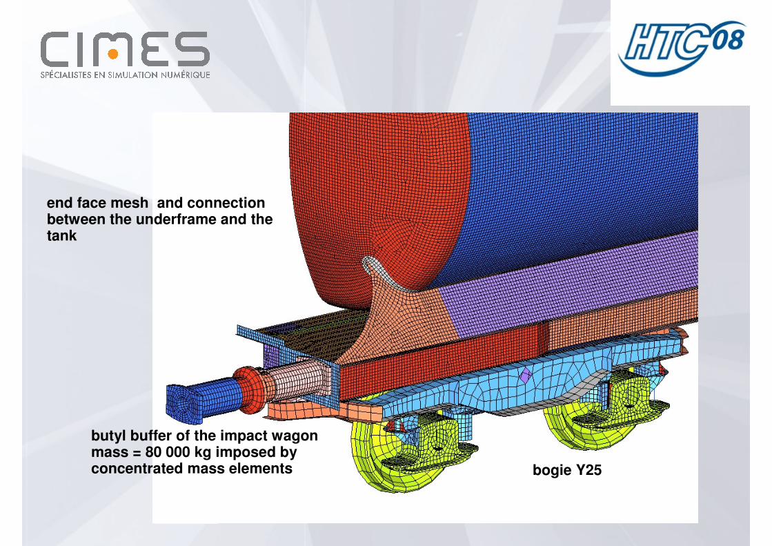
butyl buffer of the impact wagon mass = 80 000 kg imposed by concentrated mass elements bogie Y25
end face mesh and connectionbetween the underframe and thetank

water mesh : - mass = 54 tonnes- 228 495 SPH cells- smoothong lengh "h0" equal to 55 mm- mass of each particle = 120 gr- 50mm between each particle- Reference density = 0.001 gr/mm3
- liquid EOS = 2200 N/mm2 liquid bulk modulus- SPH symmetry condition
contact interface between the tank (shell finite elements) and the water (SPH cells) is modelled using a sliding interface (type 7)
butyl buffer ofthe test wagon

Simulation results
The simulation results are compared to the experimental data with regard to thecompressive force on the buffers, acceleration of the vehicle and stressesouputs on the connection between the underframe and the tank.

Kinematic of the sloshing test
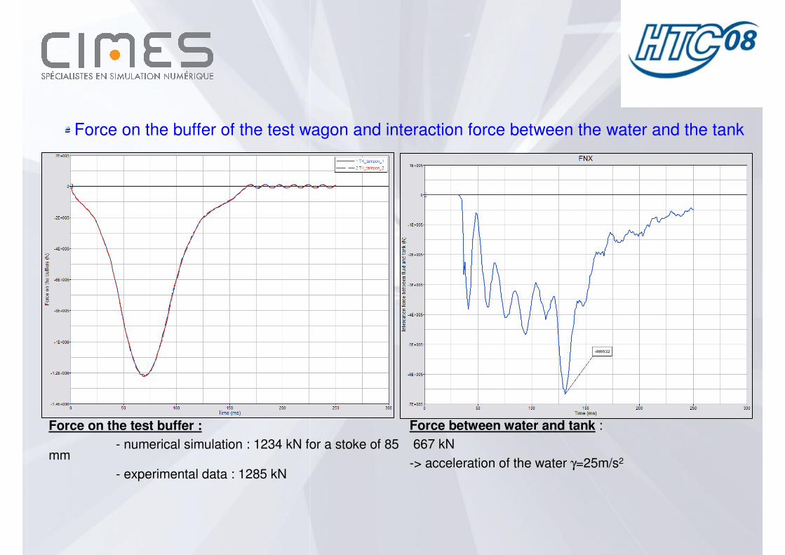
Force on the test buffer :
- numerical simulation : 1234 kN for a stoke of 85 mm
- experimental data : 1285 kN
Force between water and tank :
667 kN
-> acceleration of the water γ=25m/s2
Force on the buffer of the test wagon and interaction force between the water and the tank

Acceleration of the test wagon
acceleration of the test wagon γ=80m/s2
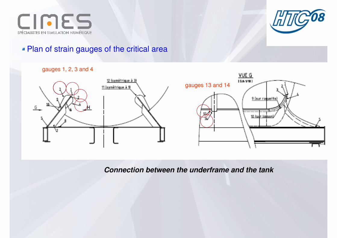
Plan of strain gauges of the critical area
Connection between the underframe and the tank
gauges 1, 2, 3 and 4
gauges 13 and 14
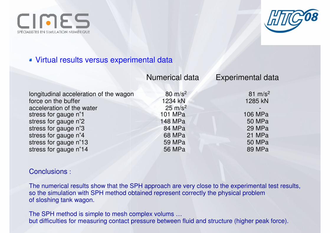
Virtual results versus experimental data
Numerical data Experimental data
longitudinal acceleration of the wagon 80 m/s2 81 m/s2
force on the buffer 1234 kN 1285 kNacceleration of the water 25 m/s2 -stress for gauge n°1 101 MPa 106 MPastress for gauge n°2 148 MPa 50 MPastress for gauge n°3 84 MPa 29 MPastress for gauge n°4 68 MPa 21 MPastress for gauge n°13 59 MPa 50 MPastress for gauge n°14 56 MPa 89 MPa
Conclusions :
The numerical results show that the SPH approach are very close to the experimental test results, so the simulation with SPH method obtained represent correctly the physical problemof sloshing tank wagon.
The SPH method is simple to mesh complex volums …but difficulties for measuring contact pressure between fluid and structure (higher peak force).