simulation of fuzzy logic based upqc by addition of a
TRANSCRIPT

IJRECE VOL. 6 ISSUE 3 ( JULY - SEPTEMBER 2018) ISSN: 2393-9028 (PRINT) | ISSN: 2348-2281 (ONLINE)
INTERNATIONAL JOURNAL OF RESEARCH IN ELECTRONICS AND COMPUTER ENGINEERING
A UNIT OF I2OR 1740 | P a g e
Simulation of Fuzzy Logic Based UPQC by
Addition of a Superconducting Magnetic Energy
Storage System M Sravani
M-tech Student Scholar
Department of Electrical & Electronics Engineering,
St. Peters Engineering College, Maisammaguda,
Hyderabad, Telangana, India.
Dr. Jayanna Kanchikere
Professor
Department of Electrical & Electronics Engineering,
St. Peters Engineering College, Maisammaguda,
Hyderabad, Telangana, India.
Abstract- Modern power grids must be highly reliable and
provide power with a high quality. Power quality issues like
voltage sags or current harmonics must be minimized, in
order to achieve high levels of reliability in the system. One
possible way to overcome such problems is through the
utilization of active power filters like a Unified Power
Quality Conditioner (UPQC).As the demand of electricity is
increasing day by day, it is necessary to supply a good
quality of power to customers. In the future, distribution
system operators could decide to supply their customers with
different PQ levels and at different prices. Due to the
presence of nonlinear loads in the system many problems
like fluctuations, flickers, voltage sag, voltage swell etc.
comes in the system. Series compensator which is meant for
voltage restoring is controlled by a fuzzy logic controller.
Shunt compensator’s operation is controlled by extracting d
and q axis current from load current and DC link voltage is
maintained through a fuzzy logic controller. The
performance of UPQC mainly depends upon how quickly
and accurately compensation signals are derived. Thus, the
combination of weak grids, wind power fluctuation and
system load changes produce disturbances in the PCC
voltage, worsening the Power Quality is stability. In this
paper, a fuzzy logic controller with reference signal
generation method is designed for UPQC. This is used to
compensate current and voltage quality problems of
sensitive loads. The results are analyzed and presented using
Matlab/Simulink software.
Keywords—UPQC; SMES; Power Quality.
I. INTRODUCTION
The limited stretch of time Power Quality (PQ) are most
important facets of any power way of using voice system
today. feeble amount of power quality has an effect on
user and can cause loss of producing, damage of
appliances and necessary things, increase the power loss
and so forward, out, on (in time). In present scenario the
use of necessary things based on power electronics has
produce force of meeting blow on power quality by
harmonics [1-2].
Power Quality is a function of power factor so the use of
non-linear and low power factor load such as adjustable
speed drives, computer power supplies, furnaces, power
converters and traction drives are finding its applications
at domestic and industrial levels. These nonlinear loads
draw non-linear current and degrade electric power
quality. The prime objective of power utility companies is
to provide their consumers an uninterrupted sinusoidal
voltage of constant amplitude [3-4].
These devices can be of series, shunt-shunt or series-shunt
type [5]. The main advantage of multi feeder devices is
that if any power quality problem occurs in one feeder,
other adjacent feeder supplies power for compensating
power quality problem. Therefore the multi-feeder PQ
devices assure superior performance than single feeder
PQ devices [6]. Unified Power Quality Conditioner
(UPQC) consists of two IGBT based Voltage source
converters (VSC), one shunt and one series cascaded by a
common DC bus. The shunt converter is connected in
parallel to the load. It provides VAR support to the load
and supply harmonic currents. Whenever the supply
voltage undergoes sag then series converter injects
suitable voltage with supply [7]. Thus UPQC improves
the power quality by preventing load current harmonics
and by correcting the input power factor. In addition,
when the active rectifier inside UPQC is used as a power
factor corrector, DC bus voltage oscillations appears
which makes the control of the series filter output voltage
more difficult. Before mentioned problems are overcome
by using voltage source inverter (VSI). VSI-based UPQC
has a faster phase voltage control loop and inherent short
circuit protection capability. It also minimizes the cost as
in this case passive filter connection between UPQC and
the load is not necessary [8-9].
The only disadvantage of VSI-based UPQC is that its dc
link inductor is bulky and heavy which leads to high dc
link losses. It uses synchronously rotating frame to derive
reference signals, which has increased time delay in
filtering dc quantities. The concept of FLC is to utilize the

IJRECE VOL. 6 ISSUE 3 ( JULY - SEPTEMBER 2018) ISSN: 2393-9028 (PRINT) | ISSN: 2348-2281 (ONLINE)
INTERNATIONAL JOURNAL OF RESEARCH IN ELECTRONICS AND COMPUTER ENGINEERING
A UNIT OF I2OR 1741 | P a g e
qualitative knowledge of a system to design a practical
controller [10]. For a process control system, a fuzzy
control algorithm embeds the intuition and experience of
an operator, designer and researcher. The control does n‟t
need accurate mathematical model of a plant, and
therefore, it suits well to a process where the model is
unknown or ill-defined and particularly to systems with
uncertain or complex dynamics [11]. In this paper the
application of fuzzy logic in control of shunt and series
active power filters used a hysteresis band comparator for
control of three-phase active power filter. This paper
presents a novel method for derivation of compensation
signals in VSI-based UPQC using Fuzzy logic Controller.
The performance of the system is verified by extensive
simulation [12].
In recent years, FACTS has appeared as solution of many
PQ problems. The FACTS concepts applied in
distribution systems has resulted in a new generation of
compensating devices. A UPQC is the extension of the
UPFC concept at the distribution level. UPQC is the
integration of Series APF and shunt APF, active power
filters, connected back-to-back on the dc side, sharing a
common DC capacitor. The series component of the
UPQC is responsible for mitigation of the supply side
disturbances: voltage sags/swells, flicker, voltage
unbalance and harmonics [13]. It inserts voltages so as to
maintain the load voltages at a desired level; balanced and
distortion free. The shunt component is responsible for
mitigating the current quality problems caused by the
consumer: poor power factor, load harmonic currents,
load unbalance etc. It injects currents in the ac system
such that the source currents become balanced sinusoids
and in phase with the source voltages.
The overall function of UPQC mainly depends on the
series and shunt APF controller.
A. Block Diagram of UPQC
The system configuration of a single-phase UPQC is
shown in figure given below.
Fig.1.Block Diagram of UPQC.
UPQC consists of two IGBT based VSC, one shunt and
one series cascaded by a common DC bus. The main
components of a UPQC are series and shunt power
converters, DC capacitors, low-pass and high-pass passive
filters, and series and shunt transformers. The key
components of this system are as follows.
1) Two inverters —one connected across the load which
acts as a shunt APF and other connected in series with the
line as that of series APF.
2) Shunt coupling inductor L is used to interface the shunt
inverter to the network. It also helps in smoothing the
current wave shape.
3) A common dc link that can be formed by using a
capacitor or an inductor.
4) An LC filter that serves as a passive low-pass filter and
helps to eliminate high-frequency switching ripples on
generated inverter output voltage.
5) Series injection transformer that is used to connect the
series inverter in the network. A suitable turn ratio is
often considered to reduce the voltage and current rating
of series inverter.
6)The integrated controller of the series and shunt APF of
the UPQC to provide the compensating voltage reference
Vc and compensating current reference Ic.
II.SYSTEM OVERVIEW
The designed system is depicted in Fig.2. The
simulated grid contains a power source, which was
simulated using a three phase programmable power
source in Simulink, a pure resistive load and the hybrid
system consisting of the UPQC+SMES. The series active
filter that builds the UPQC is placed close to the power
source and the shunt filter is placed close to the load.
Although it is possible to choose a reverse configuration
(shunt filter close to the source and series filter close to
the load) this arrangement was chosen because it allows a
better controllability of the DC bus voltage. This is a
fundamental characteristic in this hybrid system because
the SMES is connected to this DC bus.
Fig.2.Implemented system.
A.UPQC
The UPQC is the main component of the designed
system. Fig.2 shows a schematic of the implemented
active power filter. The UPQC flexibility allows a full
control of voltage and current. The series power active
filter is responsible for voltage control and the shunt filter

IJRECE VOL. 6 ISSUE 3 ( JULY - SEPTEMBER 2018) ISSN: 2393-9028 (PRINT) | ISSN: 2348-2281 (ONLINE)
INTERNATIONAL JOURNAL OF RESEARCH IN ELECTRONICS AND COMPUTER ENGINEERING
A UNIT OF I2OR 1742 | P a g e
for current control. This control is possible by measuring
the different values of voltages and currents in the grid
and comparing them to reference values. The two filters
are controlled using PWM generators and follow two
different control strategies: the reference signal for the
PWM generator of the series filter follows a
“feedforward” control method, comparing the voltage of
the filter to a well-defined reference value; on the other
hand, the reference signal for the PWM generator of the
shunt filter is obtained following a Synchronous
Reference Frame Method [5]. A major responsibility of
the UPQC controller is to maintain the DC bus voltage
always above a required level. On this particular case, the
chosen value is 700 V, which is higher than the minimum
voltage necessary to have full controllability of both
active filters at all time. The minimum value in this case
is 648V, calculated following the formulation presented.
The capacitor used in the DC bus has a value of 50 µF.
Fig.3. Implemented UPQC
B.SMES
An SMES is a very complex system, composed by
three main components: a superconducting (SC) coil
(placed inside a cryostat) where energy is stored; a Power
Converter System (PCS), which is a power electronics
bidirectional converter, responsible for the exchange of
energy with the grid to which the SMES is connected, and
a Control System (CS) responsible for controlling all
energy exchanges with the grid and also for over viewing
and protecting the conditions of the SC coil. Fig.4 depicts
a typical configuration of the systems
Fig.4.SMES system constitution.
In this particular case, because it is a simulation work and
because the SMES is connected to a DC bus, several
simplifications are possible. The PCS becomes simpler
than the used one when the SMES is connected to an AC
grid. In this case, it is necessary to use only a DC/DC
converter. The typical choice is a chopper converter, due
to its simplicity. The control strategy used in the PCS also
becomes simpler due to this fact, which will also decrease
the complexity of the CS. Other simulations are
performed on the controller of the SMES: all variables
related to the cryogenic system and protection of the SC
coil are not considered. However, since the hybrid system
is supposed to be able to overcome voltage swells, it is
necessary to add a resistor in parallel with the SC coil, so
that the excess energy (in case of a voltage swell) can be
dissipated. This dissipation of energy will only occur if
the SMES is already fully charged. The model used for
simulation of the SMES is represented in Fig.5. To
simulate the chopper two IGBTs (𝑆1 and 𝑆2 ) were used.
Fig.5.SMES model.
IJRECE VOL. 6 ISSUE 3 ( JULY - SEPTEMBER 2018) ISSN: 2393-9028 (PRINT) | ISSN: 2348-2281 (ONLINE)
INTERNATIONAL JOURNAL OF RESEARCH IN ELECTRONICS AND COMPUTER ENGINEERING
A UNIT OF I2OR 1743 | P a g e
The control of these two switches allows the SMES to
work in three different modes:
S1 and S2 closed – Charging Mode: the coil is
charging;
S1 S2 closed – Discharging Mode: the coil is
discharging, due to the occurrence of some fault
in the grid;
S1 open and S2 closed – Persistent Mode: the
coil is already full charged and its nominal
current value is kept using this mode.
When the SMES is operating alone, the charging process
is straightforward. The energy can be extracted from the
DC link without any special care. However, in this
particular case, since the SMES is connected to the DC
bus of an UPQC, its the charging process must take into
account the fact that the DC voltage cannot decrease
below a certain level. Thus, it is only possible to charge
the SMES when the DC voltage is above 700 V (the
chosen value for the DC bus voltage). The controller of
the SMES (which controls the IBGTs S1 and S2) must
consider this aspect.
The main characteristics from the SMES unit
simulated in this work are presented in table I such
characteristics were obtained following the method
presented. The implemented model also considers a
resistor (with 0.1 Ω) in series with the coil, to simulate the
existence of connectors in the superconducting tape and a
capacitor (with 1nF) in parallel, to simulate capacitance
between the single pancake coils. TABLE I
Characteristics Of The Simulated SMES Unit.
In an UPQC operating alone, in the same
conditions as in this case, i.e., the same DC voltage (700
V) and the same capacitor in the DC bus (50 µF), the
stored energy is 12.25 J.This is a small value, which
strongly limits the range of applications of such system,
namely when used for voltage sags compensation. In this
case, with an SMES with these characteristics connected
to the DC link of the UPQC, the stored energy increases
to 698.25 J. This represents an increase of 5700% in
stored energy, which greatly expands the range of
application of the hybrid system, when comparing to the
UPQC alone.
C.FAULT DETECTION
To be able to overcome faults, it is first necessary to
correctly and rapidly identify those events in the grid.
Voltage sags and swells are detected following a method
presented. Briefly, this method detects a voltage sag or
swell by comparing the grid voltage value with a
reference value. This reference value has the same phase
and amplitude as the nominal voltage of the grid, which is
very convenient because this is also used as a reference
for the series active power filter.
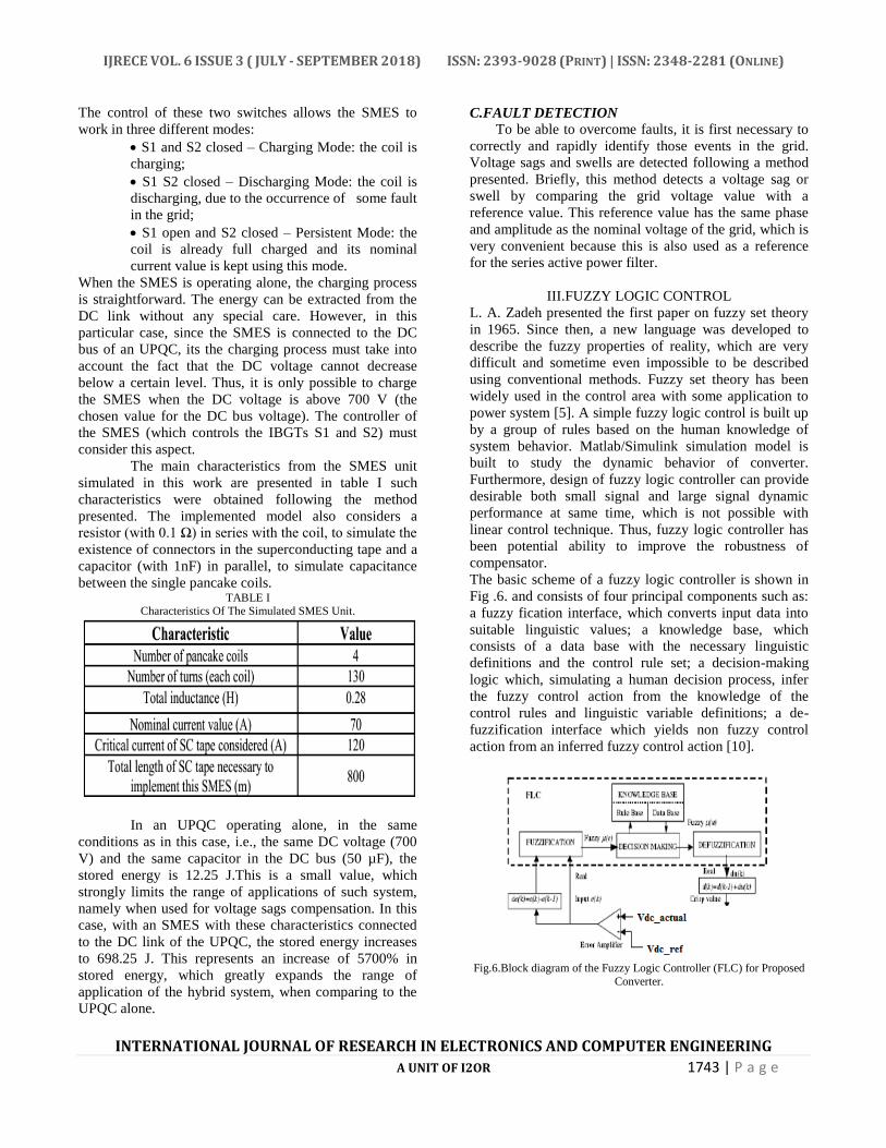
III.FUZZY LOGIC CONTROL
L. A. Zadeh presented the first paper on fuzzy set theory
in 1965. Since then, a new language was developed to
describe the fuzzy properties of reality, which are very
difficult and sometime even impossible to be described
using conventional methods. Fuzzy set theory has been
widely used in the control area with some application to
power system [5]. A simple fuzzy logic control is built up
by a group of rules based on the human knowledge of
system behavior. Matlab/Simulink simulation model is
built to study the dynamic behavior of converter.
Furthermore, design of fuzzy logic controller can provide
desirable both small signal and large signal dynamic
performance at same time, which is not possible with
linear control technique. Thus, fuzzy logic controller has
been potential ability to improve the robustness of
compensator.
The basic scheme of a fuzzy logic controller is shown in
Fig .6. and consists of four principal components such as:
a fuzzy fication interface, which converts input data into
suitable linguistic values; a knowledge base, which
consists of a data base with the necessary linguistic
definitions and the control rule set; a decision-making
logic which, simulating a human decision process, infer
the fuzzy control action from the knowledge of the
control rules and linguistic variable definitions; a de-
fuzzification interface which yields non fuzzy control
action from an inferred fuzzy control action [10].
Fig.6.Block diagram of the Fuzzy Logic Controller (FLC) for Proposed
Converter.

IJRECE VOL. 6 ISSUE 3 ( JULY - SEPTEMBER 2018) ISSN: 2393-9028 (PRINT) | ISSN: 2348-2281 (ONLINE)
INTERNATIONAL JOURNAL OF RESEARCH IN ELECTRONICS AND COMPUTER ENGINEERING
A UNIT OF I2OR 1744 | P a g e
Fig.7. Membership functions for Input, Change in input, Output.
Rule Base: the elements of this rule base table are
determined based on the theory that in the transient state,
large errors need coarse control, which requires coarse in-
put/output variables; in the steady state, small errors need
fine control, which requires fine input/output variables.
Based on this the elements of the rule table are obtained
as shown in Table, with ‘Vdc’ and ‘Vdc-ref’ as inputs
IV.MATLAB/SIMULATION RESULTS
Fig.8.Simulation model of superconducting magnetic energy system of
UPQC.
Fig.9.Harmonic distortion compensation: source (above) and load
(below) voltages.
Fig.10.Voltage sag elimination: source (above) and load (below)
voltages during the fault.
Fig. 11. Current in the SMES during a three phase voltage sag.

IJRECE VOL. 6 ISSUE 3 ( JULY - SEPTEMBER 2018) ISSN: 2393-9028 (PRINT) | ISSN: 2348-2281 (ONLINE)
INTERNATIONAL JOURNAL OF RESEARCH IN ELECTRONICS AND COMPUTER ENGINEERING
A UNIT OF I2OR 1745 | P a g e
Fig.12.Voltage swell elimination: source (above) and load (below)
voltages during the fault
Fig.13.Simulation model of fuzzy logic controller.
Fig.14.Harmonic distortion compensation: source (above) and load
(below) voltages with fuzzy logic controller.
V.CONCLUSION
The UPQC has been simulated using the proposed FC. It
may be noticed that the source current is distorted before
connecting the UPQC and it becomes sinusoidal after
connecting the UPQC. This may not be desirable in
modern power system control. Using conventional
compensator data, a fuzzy logic controller (FLC) is tuned
with large number of data points. Then conventional
compensator was replaced with fuzzy logic controller and
simulated using Matlab/Simulink for RL load using
uncontrolled rectifier. The simulation results have shown
that the UPQC perform better with FLC proposed scheme
eliminates both voltage as well as current harmonics
effectively. It is also observed that the response time for
derivation of compensation signals reduces significantly
with improved accuracy
VI. REFERENCES [1]. EURELECTRIC, Power Quality in European Electricity
Supply Networks, Second Edi. Brussels, 2003, p. 64.
[2]. N. G. Hingorani and L. Gyugyi, Understanding FACTS.
IEEE, 1999.
[3]. H. Akagi, “New trends in active filters for power
conditioning,” IEEE Trans. Ind. Appl., vol. 32, no. 6, pp.
1312–1322, 1996.
[4]. H. Akagi, E. H. Watanabe, and M. Aredes, Instantaneous
Power Theory and Applications to Power Conditioning.
Hoboken, NJ, USA: John Wiley & Sons, Inc., 2007.
[5]. M. H. Rashid, Ed., Power Electronics Handbook. Elsevier,
2011.
[6]. W. V. Hassenzahl, D. W. Hazelton, B. K. Johnson, P.
Komarek, M. Noe, and C. T. Reis, “Electric power
applications of superconductivity,” Proc. IEEE, vol. 92, no.
10, pp. 1655–1674, Oct. 2004.
[7]. A. P. Malozemoff, J. Maguire, B. Gamble, and S. Kalsi,
“Power applications of high-temperature superconductors:
status and perspectives,” IEEE Trans. Appiled Supercond.,
vol. 12, no. 1, pp. 778– 781, Mar. 2002.
[8]. N. Amaro, J. Murta Pina, J. Martins, and J. M. Ceballos,
“SUPERCONDUCTING MAGNETIC ENERGY
STORAGE – A Technological Contribute to Smart Grid
Concept Implementation,” in Proceedings of the 1st
International Conference on Smart Grids and Green IT
Systems, 2012, pp. 113–120.
[9]. K. Shikimachi, H. Moriguchi, N. Hirano, S. Nagaya, T. Ito,
J. Inagaki, S. Hanai, M. Takahashi, and T. Kurusu,
“Development of MVA Class HTS SMES System for
Bridging Instantaneous Voltage Dips,” IEEE Trans. Appl.
Supercond., vol. 15, no. 2, pp. 1931–1934, Jun. 2005.
[10]. A. Friedman, N. Shaked, E. Perel, F. Gartzman, M.
Sinvani, Y. Wolfus, D. Kottick, J. Furman, and Y.
Yeshurun, “HT-SMES operating at liquid nitrogen
temperatures for electric power quality improvement
demonstrating,” IEEE Trans. Appl. Supercond., vol. 13, no.
2, pp. 1875–1878, Jun. 2003.
[11]. A.-R. Kim, S.-Y. Kim, K.-M. Kim, J.-G. Kim, S. Kim, M.
Park, I. Yu, S. Lee, M. Sohn, H. Kim, J. Bae, and K. Seong,
“Performance Analysis of a Toroid-Type HTS SMES
Adopted for Frequency Stabilization,” IEEE Trans. Appl.
Supercond., vol. 21, no. 3, pp. 1367–1370, Jun. 2011.
[12]. Y. Makida, H. Hirabayashi, T. Shintomi, and S. Nomura,
“Design ofSMES System With Liquid Hydrogen for
Emergency Purpose,” IEEETrans. Appl. Supercond., vol.
17, no. 2, pp. 2006–2009, Jun. 2007.
[13]. R. Kreutz, H. Salbert, D. Krischel, A. Hobl, C.
Radermacher, N. Blacha, P. Behrens, and K. Dutsch,
“Design of a 150 kJ high-Tc SMES (HSMES) for a 20 kVa
uninterruptible power supply system,” IEEE
[14]. Trans. Appl. Supercond., vol. 13, no. 2, pp. 1860–1862,
Jun. 2003.