simulation components - defense technical information … · cranfield university uk...
TRANSCRIPT
RTO-EN-MSG-043 6 - 1
Simulation Components
Mr. Jonathan Searle, Mr. John Brennan Simulation and Synthetic Environment Laboratory (SSEL)
Defence Academy of the United Kingdom Cranfield University
UK
[email protected] / [email protected]
INTRODUCTION
The fundamental concept of simulation dates back thousands of years to the ancient Egyptians and the famous Chinese war strategist SunTzu. Notwithstanding these initial attempts at replicating ancient battlefields, current day machine-based modelling and simulation (M&S) found its roots in the early 20th Century. During this dawning era, the majority of M&S efforts were carried out in isolation. One may not find this so surprising when one considers the fundamental definition of a model: a representation of an element of the real world for a specific purpose. Working in isolated domains on specific applications, M&S developers created bespoke solutions to precise problems.
Modelling and simulation has undergone a significant maturation process over the past few decades. Early on, the M&S realm represented only a very small portion of the real world (see Figure 1(a)). Systems such as flight simulators, SimNet1 and operational analysis (OA) models, although based on real world requirements, had no direct physical connection to the real world domains. Technology growth led to an expansion within the M&S realm, allowing practitioners to address a larger subset of real world applications with more comprehensive and complex representations (see Figure 1(b)). Today, the M&S realm has achieved an overlap with the real world wherein simulation information is viewed coincident with the real world2.
Figure 1: Growth in Modelling & Simulation.
1 SimNet (Simulation Networking), considered to be the birth of distributed simulation, was the result of a DARPA project to create a network of real time, man-in-the-loop simulators for the US Army. See http://www.peostri.army.mil/PRODUCTS/ PC_BASED_TECH/ for more information.
2 This concept is referred to as augmented or mixed reality. For more information see http://www.informationinplace.com/ .
Searle, J.; Brennan, J. (2006) Simulation Components. In Integration of Modelling and Simulation (pp. 6-1 – 6-12). Educational Notes RTO-EN-MSG-043, Paper 6. Neuilly-sur-Seine, France: RTO. Available from: http://www.rto.nato.int/abstracts.asp.

Report Documentation Page Form ApprovedOMB No. 0704-0188
Public reporting burden for the collection of information is estimated to average 1 hour per response, including the time for reviewing instructions, searching existing data sources, gathering andmaintaining the data needed, and completing and reviewing the collection of information. Send comments regarding this burden estimate or any other aspect of this collection of information,including suggestions for reducing this burden, to Washington Headquarters Services, Directorate for Information Operations and Reports, 1215 Jefferson Davis Highway, Suite 1204, ArlingtonVA 22202-4302. Respondents should be aware that notwithstanding any other provision of law, no person shall be subject to a penalty for failing to comply with a collection of information if itdoes not display a currently valid OMB control number.
1. REPORT DATE 01 SEP 2006
2. REPORT TYPE N/A
3. DATES COVERED -
4. TITLE AND SUBTITLE Simulation Components
5a. CONTRACT NUMBER
5b. GRANT NUMBER
5c. PROGRAM ELEMENT NUMBER
6. AUTHOR(S) 5d. PROJECT NUMBER
5e. TASK NUMBER
5f. WORK UNIT NUMBER
7. PERFORMING ORGANIZATION NAME(S) AND ADDRESS(ES) Simulation and Synthetic Environment Laboratory (SSEL) DefenceAcademy of the United Kingdom Cranfield University UK
8. PERFORMING ORGANIZATIONREPORT NUMBER
9. SPONSORING/MONITORING AGENCY NAME(S) AND ADDRESS(ES) 10. SPONSOR/MONITOR’S ACRONYM(S)
11. SPONSOR/MONITOR’S REPORT NUMBER(S)
12. DISTRIBUTION/AVAILABILITY STATEMENT Approved for public release, distribution unlimited
13. SUPPLEMENTARY NOTES See also ADM001943., The original document contains color images.
14. ABSTRACT
15. SUBJECT TERMS
16. SECURITY CLASSIFICATION OF: 17. LIMITATION OF ABSTRACT
UU
18. NUMBEROF PAGES
54
19a. NAME OFRESPONSIBLE PERSON
a. REPORT unclassified
b. ABSTRACT unclassified
c. THIS PAGE unclassified
Standard Form 298 (Rev. 8-98) Prescribed by ANSI Std Z39-18

Simulation Components
6 - 2 RTO-EN-MSG-043
The advances and growth referred to above has resulted in a virtual explosion in the elements and components associated with simulation. These components can be divided into two categories: those associated with the science and technology of simulation itself; and those more closely related to the human and cultural aspects of the M&S community. The first section of this paper introduces the concept of synthetic environments as a means of establishing some common ground for further discussion. The remainder of the paper will take a closer look at some of the technical and non-technical components of simulation.
SYNTHETIC ENVIRONMENTS There is a variety of ways in which one can categorise the many models and simulations in use today. One of the most common, top-level taxonomies used by the military is the live, virtual, constructive (LVC) triplet (see Figure 2). This categorisation addresses the method of simulation conduct by specifying the role and representation of people and equipment in the environment. Another way of looking at models and simulations is the application domain for which they were developed. In this instance, one can conceivably classify models into one of the following categories: analytical, engineering, training, and testing. These two methods of categorisation do not preclude underlying fundamental groupings such as mathematical, 3-dimensional and process models. Furthermore, one must remain aware of the potential to use or reuse models (or components thereof) across multiple domains, where applicable3. Regardless of the taxonomy used, one must understand that there is a large array of models and simulations; some models exist to serve a very specific, narrowly focused purpose, while others were designed to be more flexible and address a range of options within their domains. Thus, categorisation can serve as a management and understanding aid, and it must be approached with an open mind.
Figure 2: Live, Virtual and Constructive Simulation Definitions.
The precise understanding of the phrase synthetic environment (SE) can vary from organisation to organisation. The US DoD typically interprets this phrase as meaning the representation of the real world environment (terrain, ocean, atmosphere) in simulation. The UK MoD and the Canadian DND view a SE as a gathering of simulations, people and equipment via a distributed network in a common representation of an element of the real world. The UK MoD definition of a SE is:
“A computer-based representation of the real world, usually a current or future battle space, within which any combination of ‘players’ may interact. The ‘players’ may be computer models, simulations, people or instrumented real equipments.”
http://www.mod.uk/issues/simulation/policy.htm
3 The practice of reusing a model for purposes other than for which it was developed must be approached with caution – detailed research must be undertaken to ensure valid and usable output will be generated for the newer application of the model.

Simulation Components
RTO-EN-MSG-043 6 - 3
The Canadian DND definition of a SE is:
“The linkage of models, simulations, people (real or simulated), equipment (real or simulated) into a common representation of the world.”
http://www.drdc-rddc.gc.ca/seco/library_e.html The key point to keep in mind is that there is no single SE. Synthetic environments, similar to models, are established for specific purposes (e.g. a synthetic environment for allowing C-130 pilots to mission rehearse in tactical air lift would be quite different from a synthetic environment that would be used to conduct developmental test and evaluation on a towed array sonar system).
To assist in generating a more detailed understanding of the simulation components that comprise a synthetic environment, it is helpful to examine the elements that are involved in a real world exercise or operation. Figure 3 lists the typical elements of a military activity on the left. These elements are mapped to simulation components that are applicable to the discussion to follow in this paper (not an exhaustive list). Note that there are technical and non-technical elements components within the simulation realm, much like there are operational and non-operational elements in the real world. The remainder of this paper will examine the technical and non-technical simulation components.
Figure 3: Simulation Component Mapping.
THE TECHNICAL COMPONENTS
When one encounters the term simulation, particularly in a military environment, typically the first image that enters one’s mind is that of a high-tech computer-based simulator primarily used for skills training for a single individual. Advances in technology are increasing the scope of technology application, which in turn is helping to broaden this first impression. Nonetheless, it is normal for one to think of the technical aspects (or components) of simulation in the first instance due to the highly technical nature of the subject.
An aspect of military simulation with which many people are unaware is the existence of countless elements which are out of sight of the typical user or observer. This section will focus on these types of components, addressing each category one at a time, and finish with a brief look at a typical simulator as a means of leading into the next section.

Simulation Components
6 - 4 RTO-EN-MSG-043
Computer Generated Forces Computer Generated Forces (or CGF) is a broadly applied term for the most part. In the literature, it is commonly interchanged with synthetic forces (SF), semi-autonomous forces (SAF), intelligent forces (IFOR), command forces (CFOR), command agents (CA) and many more like terms. One way of looking at it is that all of these alternate terms imply a specialist application (for example command & control for CFOR or CA), while CGF is a more general term.
Essentially, a CGF is a computer-based representation of a participant within a given scenario. The participant being represented can be at one of a selection of different levels (i.e. platform or aggregate4); however, the individual element represented is typically at the lowest level of command & control relevant to the scenario. For example, in a tactical level simulation, a CGF entity might be an individual soldier or aircraft, while in a strategic level simulation, a CGF entity might be a naval task force consisting of six to ten different vessels, clustered together and represented by a single icon.
Regardless of the level of representation generated, CGFs are typically defined and designed from two perspectives: physical and behavioural. The physical representation of a CGF entity is the representation one would normally imagine when considering such a component. It is also, by nature, the easier of the two representations to define. Physical representation consists of elements such as dimensions, manoeuvrability and sensors. The more difficult element of representation is that of behaviour. This is typically accomplished by identifying the knowledge and decision making abilities that the parallel real-world entity would possess, drawing on such things as military doctrine, techniques and procedures. One could also allow for the entity to be assigned tasks and the sense of responsibility for completing mission objectives. Another option would be for command forces to understand their position within the command & control structure and conduct certain activities based on this perceived position.
Finally, CGFs offer a means by which military organisations can ease the burden of the need to provide skilled and trained operators in large numbers to conduct simulation based activities. By leveraging the power in CGFs, one operator can conceivably control a multitude of friendly, enemy or neutral entities given a proper user interface and provided the CGFs possess sufficient behavioural characteristics.
Image Generation (Graphics) Image generation (IG), or computer graphics, is a topic that is receiving considerable attention as of late. Rapid advances in 3-D graphics processing have taken the computer-based gaming world by storm. It is important to note that real-time 3-D graphics is not the only means of computer generated imagery (CGI); however, it is arguably the most difficult to design and the most computationally intense to produce. Therefore 3-D real-time (or near real time) IG will be the focus of this segment.
Most people will be somewhat familiar with Moore’s Law that states the processing power (or transistors in a CPU) will double approximately every two years[i]. Somewhat lesser known is the fact that IG technology is growing at an even faster rate; on average, graphics processing units (or GPUs) double their capability every six months. Figure 4 depicts a comparison between the growth rates of CPUs and GPUs. Furthermore, while the capability of IGs has been improving, their associated costs have been declining.
4 Aggregate being the grouping or combination of individual platforms or participants into a cohesive element or entity
represented by a single icon or symbol within the simulation space.

Simulation Components
RTO-EN-MSG-043 6 - 5
Figure 4: GPU versus CPU Growth Rate (University of North Carolina).
To illustrate this apparent explosion in value for money, one can examine the hardware from the UK Defence Academy Simulation and Synthetic Environment Laboratory (SSEL) over the past 10 years. Table 1 lists the platforms used for 3-D IG and their associated price-performance index. Using 1995 as a baseline, one can see that over a 10 year period the SSEL has seen a 4000 times increase in price-performance.
Table 1: Graphics Processing Price Performance
1995 2001 2004 SGI Onyx RE 256 MB RAM £250,000 Performance X 1 PricePerf : 1
Dual CPU P III – 1 GHz 512 MB RAM £4,500 Performance X 10 PricePerf: 500
Pentium 4 HT 3.2 GHz 1 GB RAM £1,300 Performance X 20 PricePerf: 4000
As has been mentioned, this rather dramatic increase in capability has evolved over the past two decades through multiple generations of IG hardwareii (Figure 5):
• 1st Generation (up to 1980s) – First generation real time IG hardware allowed primarily wireframe models to be built and manipulated (e.g. computer aided design applications.
• 2nd Generation (1980s to 1992) – Second generation hardware saw the implementation of shaded solid objects.
• 3rd Generation (1992 to 2000) – Third generation hardware gave rise to texture mapping, wherein more detail could be applied to 3-D objects by painting them with more complex images rather a single colour.
• 4th Generation (2000 to ?) – Current generation real time IG hardware allows one to program the image generation pipeline.
• 5th Generation (?) – The next generation IG hardware has the potential to implement correct lighting physics, which until now has not been possible in the real time realm.

Simulation Components
6 - 6 RTO-EN-MSG-043
Figure 5: IG Advances.
One can confidently state that image generation has become one of the primary components in the realm of simulation, particularly in the military training and education arena. Continued progress in this area will no doubt greatly influence the manner in which future forces train and educate their personnel.
Synthetic Natural Environment Although relatively new terminology, the concepts represented by the phrase synthetic natural environment (SNE) are not new. In the past, the data that was used to represent some element of the natural environment (i.e. terrain, ocean currents, and atmospheric profiles) was collected, stored and used in isolation. Today, the data is largely still collected and stored separately; however when it comes to processing and applying the data in simulation, a variety of types are typically aggregated for use in a cohesive SNE. Some of the typical items that are of interest to the general simulation realm include:
• Terrain – elevation (with respect to a particular datum); composition (i.e. rock, soil, asphalt, forest, etc); features (rivers, trees, roads, buildings, etc).
• Water – temperature; pressure; currents; salinity; depth.
• Atmosphere – temperature; pressure; wind velocity; moisture content; altitude.
The environment that has greatest applicability to most military situations is terrain representation, especially regarding visualisation of the environment. As mentioned before, the primary elements that comprise a typical 3-D terrain database (3DTDB) are the terrain skin (or surface) and the features that rest upon it (such as railways, power lines, fields and lakes). In addition to defining the presence of terrain and any applicable features, one might have the need to define and specify other descriptive properties such as material composition and emissivity characteristics. These additional properties become important if the interacting simulations are attempting to represent such things as radar systems or thermal imaging sensors.
Within the context of interoperability and integrating M&S, a critical issue with SNE’s is correlation. One must ensure that all participants within a distributed simulation activity have not necessarily identical, but correlated databases. To illustrate this concept, consider the situation depicted in Figure 6. Platform B’s simulator has the data and the ability to display multiple, individual trees; Platform A’s simulator does not. As such, Platform B is under the impression that it is well concealed in an ideal firing position. However, Platform A, unable to display the trees, perceives Platform B as being exposed. This results in what is commonly termed an unfair fight. The key point regarding SNE’s, particularly for distributed, networked simulation events, is to ensure that the environmental data and the method of portraying that data within the various simulations/simulators results in a common view and interpretation of the simulation space. Without this, the potential for generating undesirable results becomes much greater.

Simulation Components
RTO-EN-MSG-043 6 - 7
Figure 6: Terrain Miscorrelation.
Simulators The final element in this section addresses a component which, in reality, is a combination of the previous components and some extra items not addressed directly in this paper. A simulator is generally accepted to be a “device that imitates the dynamic behaviour of a real system.”[iii] Underneath the near to real human interface of most high fidelity simulators is a collection of multiple networked components, each of which might address one or more of the issues already examined in this paper, or some other function such as dynamics modelling.
Today, simulators can be found that represent air, land and ocean going platforms, as well as exoatmospheric vehicles such as the space shuttle. The remainder of this element will focus on flight simulators because they are considered to be the most mature and tightly governed subset of simulators today. The spectrum of available flight simulation devices is rather broad, encompassing 12 different categories according to regulations adopted by the Federal Aviation Authority (FAA), Transport Canada and the UK Civil Aviation Authority (CAA). It is within these categories where one can begin to see how the many components (both human interface and computational) can vary in fidelity. For instance, the FAA category of full flight simulators (FFS) (within which there are four subcategories) is differentiated from the category of flight training devices (FTD) (within which there are seven subcategories) in that FFS systems must possess visual systems and motion platforms; FTD systems are not required to incorporate a visual system or motion platform for certification. A third category is labelled PC aviation training devices (PC ATD), wherein the simulator consists of a desktop style PC that incorporates one (or more) monitors, an instrument panel and flight controls. A final component that bears mentioning is the instructor or monitor station that almost invariably accompanies FFS and FTD systems. This component facilitates the instruction and education for which the simulator was designed; the instructor station will also likely possess specialist capability to allow it to fulfil its role. In the end, a simulator, whether viewed as a single component or as a collection of many components, consists of several elements, each of which can vary in fidelity. It is this variance that must be assessed and managed, and which lead us into the next section that addresses non-technical components of simulation.
THE NON-TECHNICAL COMPONENTS
Most often, and quite understandably so, when addressing the topic of simulation, one immediately thinks of the technical aspects. Nonetheless, in addition to the hardware and software, there are a number of other issues, which, when examined, can be grouped into what one might term non-technical components. Quite

Simulation Components
6 - 8 RTO-EN-MSG-043
often the non-technical issues are not given enough attention; one could argue that if they were, many M&S efforts would be better off. Most simulation specialists are familiar with the non-technical components, and in their defence, there are dedicated working groups whose objectives are to progress and educate in these issues. That said, the typical user or observer may not be aware of the significant effort that goes on behind the scenes to enable smooth operation of the technical components. This section will look at three general groupings: standards, processes and management.
Standards There are many standards that govern the information technology realm. Likewise, a number of simulation specific standards have emerged over the past decade. Standards provide significant benefit towards achieving interoperability among disparate simulation systems and integration of simulation into many defence related processes. Given the context of this paper, this element will primarily address the relatively mature simulation interoperability standards. The interested reader is encouraged to visit the Simulation Interoperability and Standards Organization (SISO) website for more detailed information5.
The two primary current day standards concerned with interoperability and integration of networked, distributed simulation systems began as US DoD developed and supported standards. Over time, the US DoD developed and implemented an acquisition policy that calls for and favours commercial standards.[iv] As such, the Institute of Electrical and Electronic Engineers (IEEE) currently manages these two standards: Distributed Interactive Simulation (DIS) as IEEE 1278 and the high level Architecture (HLA) as IEEE 1516.
The DIS standard is a communications protocol that facilitates information exchange between simulation applications. It defines data transfer formats as well as coordinate systems and units of measure amongst many other items. As such, one might say it provides an ad-hoc interoperability process. Data exchange occurs via fixed format protocol data units (PDU), which are broadcast using a best-effort network protocol6 between simulators. DIS was designed for real-time platform level simulations and simulators, focused on technical level interoperability. The standard has a heavy dependence on man-in-the-loop simulations as it originated in the training domain.
The HLA standard specifies a formal process to design, develop, document and execute federations7 of simulations. The process (covered in the next element) is auditable and is supported by tools to assist, enhance and enforce conformance with the standard. Each federation requires object models both at the federation level and at the simulation (or federate) level. The simulation object model (SOM) for each federate specifies (among other things) the data it requires from other participants and the data other participants have requested of it; this is known as the publish and subscribe process. For more information, the interested reader should visit the Defence Modeling and Simulation Office (DMSO) website at https://www.dmso.mil/public/transition/hla/.
Regardless of the type of simulation or the application domain within which the simulation is applied, standards aim to increase the chance of successful integration. Like many other engineering or science disciplines, standards provide proven, widely accepted frameworks within which designers and developers can achieve a higher level of interoperability than if they were to create simulation applications without any guidance whatsoever.
5 SISO can be found at www.sisostds.org. 6 This is the User Datagram Protocol (UDP) – see http://en.wikipedia.org/wiki/User_Datagram_Protocol for more detail. 7 Here the HLA-specific term federation refers to a single execution/instantiation of a collection of simulations in a common,
cooperatively designed and developed synthetic environment.

Simulation Components
RTO-EN-MSG-043 6 - 9
Processes Much like standards, there are many processes within the IT realm. The software engineering world has adopted many of the elements of sound engineering principles and processes. Within the military domain of distributed simulation, the primary process that dominates the field today is the process associated with the HLA (mentioned above).
The Federation Development and Execution Process (FEDEP) is essentially a systems engineering process model tailored for HLA federation design and development. Graphically the FEDEP resembles a classic software engineering waterfall model (see Figure 7); however, as one looks closer, one discovers greater detail wherein multiple feedback loops and detailed checklists exist to help ensure a high quality output is achieved as quickly as possible. Nonetheless, experience has demonstrated that the FEDEP process can take many months (perhaps as long as a couple of years) to unfold, particularly for activities large in scope.
As a follow on to the HLA FEDEP, the European Cooperation for Long-term In Defence (EUCLID) spent three years (November 2000 to November 2003) modifying and expanding the FEDEP into the Synthetic Environment Development and Exploitation Process (SEDEP).[v] The objective of this pan-European effort was to provide a process and associated tools to mitigate the obstacles to the effective use of SEs within Europe. One element of the SEDEP is the use of generalised wording and definitions so as to not be solely dedicated to HLA technology. The SEDEP currently has no governing body; some have suggested that NATO or SISO should assume responsibility for the SEDEP. This concept of governance leads us into the final element of this section.
Figure 7: The HLA FEDEP (www.dmso.mil/public/transition/hla/).

Simulation Components
6 - 10 RTO-EN-MSG-043
Management The overall management of simulation is, in itself, a critical component to the successful integration and application of M&S. Management of simulation projects, systems or components can flow logically from some of the standards and processes already established. Unfortunately, even more so than some of the standards or processes, simulation management can often be forgotten in the frantic efforts to get the technical bits working. Nevertheless, management of simulation activities and material is a cradle to grave requirement if one aims to successfully leverage every last bit of power that simulation has to offer.
This brings forth a concept that has received considerable attention in defence organisations around the world as of late: the idea of through life simulation support or simulation/synthetic environment based acquisition. As was alluded to in the beginning of this paper, initial use of simulation was essentially stove-piped – that is, the various stages of systems acquisition and maturation may have employed simulation, but they did so in relative isolation. Within the acquisition world, cross-discipline collaboration was introduced, and thus was born the concept of integrated project teams (IPTs). Recent success within IPTs is owed largely to sound management of the information and resources associated with a project.
Modelling and simulation should essentially be treated as another tool in the toolbox; it requires careful planning, use and management. If leveraged appropriately and managed properly, the application of M&S to acquisition has the potential to enhance the early optimisation of a system or capability8. As such, some defence organisations are beginning to examine and implement what the Canadian DND has termed Simulation Support Plans (SSPs).[vi] Essentially, the requirement to produce a SSP for major acquisition projects ensures that the project team has examined and assessed the potential of employing simulation tools to enhance their processes – they will be required to manage M&S!
DATA HANDLING
One final element worth mentioning as a component of simulation falls partially in the technical realm and partially in the non-technical realm. Data handling, which in this case encompasses data collection and data analysis, is critically important to most applications of M&S. Without data handling of some sort, any M&S activity would really serve no purpose. Therefore, it is important that planning for data identification, collection and analysis begin early in the process; it must be planned as an integral element of any application of synthetic environment from the outset.
SUMMARY
This paper has emphasised the fact that there are many individual components that comprise the synthetic environment realm. The components have grown in number and complexity over time as the M&S world expanded, pushing closer to and eventually merging with the real world. The technologically focussed components no doubt form a significant part of the M&S discipline. Nonetheless, it is vital that we do not ignore the complementary components on the non-technological side – those of standards, processes and management. Without these, the use of M&S as an enabler and enhancer has the potential of losing its focus.
REFERENCES
[i] See http://www.intel.com/technology/silicon/mooreslaw/ for details.
8 History has shown that 80% - 90% of total ownership cost is determined early in the life cycle (i.e. prior to actual acquisition
beginning).

Simulation Components
RTO-EN-MSG-043 6 - 11
[ii] From Akeley & Hanrahan, http://www.graphics.stanford.edu/courses/cs448a-01-fall/
[iii] From DND SECO Lexicon http://www.drdc-rddc.gc.ca/seco/documents/MS_Lexicon_Apr02_e.html
[iv] Transition of the DoD High Level Architecture to IEEE Standard 1516, DMSO, 21 October 2005.
[v] See http://www.euclid1113.com/Euclid_Menu.htm
[vi] See Elliot & Gauvin, June 2004 http://admmatapp.dnd.ca/cosmat/dmasp/downloads/Modelling Simulation/Presentations/Elliot.ppt

Simulation Components
6 - 12 RTO-EN-MSG-043

ESD / SSEL
© Cranfield University 2005
NATO RTO Lecture SeriesNATO RTO Lecture Series MSGMSG--043043
Integration of Modelling & SimulationIntegration of Modelling & Simulation
Simulation ComponentsSimulation Components
Jonathan Searle & John BrennanDefence Academy – Cranfield University
Simulation and Synthetic Environment LaboratoryEngineering Systems Department

ESD / SSEL
© Cranfield University 2005
IntroductionIntroduction
Integration Theme
Exercises Mission Rehearsal
Scenario DesignProcess
MSG 043 LECTURE SERIESMSG 043 LECTURE SERIES

ESD / SSEL
© Cranfield University 2005
IntroductionIntroduction
Integration Theme
SimulationComponents
MSG 043 LECTURE SERIESMSG 043 LECTURE SERIES
RealWorld
SimulationRealm
ESD / SSEL
© Cranfield University 2005
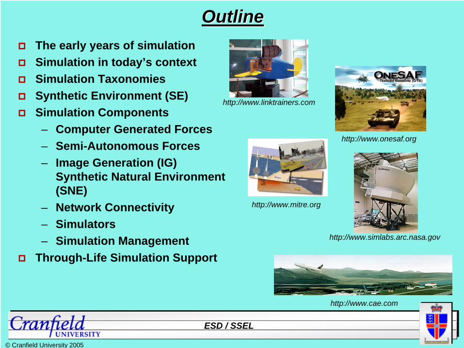
OutlineOutlineThe early years of simulationSimulation in today’s contextSimulation TaxonomiesSynthetic Environment (SE)Simulation Components– Computer Generated Forces– Semi-Autonomous Forces– Image Generation (IG)
Synthetic Natural Environment (SNE)
– Network Connectivity– Simulators– Simulation Management
Through-Life Simulation Support
http://www.linktrainers.com
http://www.onesaf.org
http://www.mitre.org
http://www.cae.com
http://www.simlabs.arc.nasa.gov

ESD / SSEL
© Cranfield University 2005
The Early YearsThe Early YearsEarly M&S was very focused– Isolated domains– Specific applications– Bespoke products
No direct connection toreal world
RealWorldM&S
OperatorTraining
OperationsAnalysis
Research

ESD / SSEL
© Cranfield University 2005
The Early YearsThe Early Years
RealWorld
OperatorTraining
OperationsAnalysis
Research
M&S
Experimentation
Testing
Technology growth leads to M&S expansionMore domainsSome linkages

ESD / SSEL
© Cranfield University 2005
TodayTodayFurther growth enables interconnectivity both between simulations and between real world elements and simulation elements.
M&SReal
World
http://www.informationinplace.com
Connectivity and interoperability leads to Synthetic Environment concept…..

ESD / SSEL
© Cranfield University 2005
Simulation TaxonomiesSimulation Taxonomies
Live Virtual Constructive
Analytic Engineering Testing
http://www.jrtc-polk.army.mil
http://icetact.tchpc.tcd.ie https://www.navo.navy.mil http://www.atec.army.mil
SSEL Crew StationSSEL TacMap
Training
http://www.cae.com

ESD / SSEL
© Cranfield University 2005
Synthetic EnvironmentSynthetic Environment
Models
Equipment People
Simulations
Consistent

ESD / SSEL
© Cranfield University 2005
Simulation ComponentsSimulation ComponentsReal World Exercise / Operation
People
Equipment
Environment
Communications
Command & Control
Tactics
Synthetic Environment
Computer Generated Forces
Semi-Autonomous Forces
Simulators
Synthetic Natural Environment
Image Generation
Network Connectivity
Simulation Management

ESD / SSEL
© Cranfield University 2005
Computer Generated Forces ?Computer Generated Forces ?
Aka:
Synthetic Forces (SF)
Semi-Automated Forces (SAF)
Intelligent Forces (IFOR)
Command Forces (CFOR)
Command Agents (CA)
Computer Generated Entities (CGE)
Computer Generated Actors (CGA)
Synthetic Entities (SE) ...
[UK MoD DSTL]

ESD / SSEL
© Cranfield University 2005
CGF BasicsCGF BasicsCGF Entity– a representation of a participant within a tactical scenario. – it can be an individual, a platform, or an aggregation. – typically it represents the lowest level of command & control
element relevant to the requirement. – usually consists of a representation of the :
– physical capabilities (e.g. mobility, firepower, sensing, logistics, etc.)
– knowledge & decision capabilities (e.g. planning, tactics, etc.)
– mission objectives & responsibilities– position in the C2 structure
[UK MoD DSTL]

ESD / SSEL
© Cranfield University 2005
Physical RepresentationPhysical Representation
Sensors
Dimensions
Manoeuvrability
Rate of Fire
Vulnerability
Signatures (aural, visual, thermal, etc.)
[UK MoD DSTL]

ESD / SSEL
© Cranfield University 2005
Behavioural RepresentationBehavioural Representation
Patrol
Reconnaissance
Ground Attack
Attack
Snipe
[UK MoD DSTL]

ESD / SSEL
© Cranfield University 2005
CGF BehaviourCGF Behaviour
– sensing and perception;
– motor skills;
– standard tactics and doctrine;
– specific mission objectives;
– situational awareness (mental models);
– physiological and psychological factors;
– decision making processes;
– short, medium and long term planning;
– enemy tactics and doctrine;
– position in the military hierarchy;
– co-operative and team working skills;
– etc …..
What types of ‘behaviour’ might be included in a CGF ?
[UK MoD DSTL]

ESD / SSEL
© Cranfield University 2005
Example types of CGFExample types of CGFSAF (Semi-Automated Forces) -– CGF that include fundamental representations of behaviour (can be
tasked and will automatically react) but which require periodic operator intervention (e.g. ModSAF Task Frames);
– They do not “learn” nor do they reason
IFOR (Intelligent Forces) – ‘Smart’ CGF that represent highly skilled individuals, or small groups,
and which are expected to operate autonomously for extended periods, while portraying credible human behaviour (e.g. Tac-Air-Soar);
CFOR (Command Forces) – CGF that represent human C2 decision making processes in a highly
complex tactical environment (e.g. Command Agents);– often used to replace human operators for monitoring SAF;
[UK MoD DSTL]

ESD / SSEL
© Cranfield University 2005
Classes of CGFClasses of CGF
‘Passive’– simple platform models, limited behavioural functionality– designed to fill-in a scenario or to provide non-combative entities
‘Reactive’– full equipment fit, with own mission objectives and reactive behaviours – may require some operator intervention– designed for flanking own forces and most enemy
‘Interactive’– designed for close interaction with manned simulators– very high fidelity modelling (e.g. similar to or same as a manned
simulator), including autonomous behaviours– good for own formation entities, immediate superiors
or subordinates, directly engaged enemy, etc.
[UK MoD DSTL]

ESD / SSEL
© Cranfield University 2005
COTS & GOTS COTS & GOTS CGFsCGFsMany “CGF” systems exist:
DoD’s ModSAF, JSAF, OTB, OOSITEMS & STRIVE-CGF - CAE’s primary productsVR-Forces - MäK Technologies’ “MäKSAF”STAGE – eNGENUITY’s simulation frameworkFLAMES – Ternion’s OA-oriented frameworkGESI – a land CGF system from CAEExportCGF – LM COTS version of ModSAFSETHI – Thales’ land warfare CGFJIMM – JSF’s SE/CGFEADSIM – Extended Air Defence SIMulation+ many more ... ‘Conventional’ constructive simulations???– eg Janus, JCATS, ABACUS, etc ???
[UK MoD DSTL]

ESD / SSEL
© Cranfield University 2005
SSEL : 1995 SSEL : 1995 vsvs 20042004
19951995SGI Onyx RESGI Onyx RE256 MB RAM256 MB RAM££250,000250,000Performance x 1Performance x 1PricePerfPricePerf : 1: 1
20012001Dual CPU PIIIDual CPU PIII--1GHz1GHz512 MB RAM512 MB RAM££4,5004,500Performance x 10Performance x 10PricePerfPricePerf : 500: 500
20042004Pentium 4 HT 3.2 GHzPentium 4 HT 3.2 GHz1 GB RAM1 GB RAM££1,3001,300Performance x 20Performance x 20PricePerfPricePerf : 4000: 4000

ESD / SSEL
© Cranfield University 2005
RT IG Hardware DevelopmentRT IG Hardware Development
1st Generation up to 198x Wireframe
2nd Generation 198x - 1992 Shaded Solids
3rd Generation 1992 - 2000 Texture Mapped
4th Generation 2000 - ???? Programmable Pipeline
5th Generation ???? Correct lighting physics?
[From Akely & Hanrahan, Stanford, 2001]
(NB Date bands only very approximate!)
1968
1981
2006

ESD / SSEL
© Cranfield University 2005
Synthetic Natural EnvironmentSynthetic Natural Environment
Terrain
Atmosphere
Bodies of Water
Above MSL
Below MSL
Composition
Temperature
Pressure
Wind Velocity
Moisture Content
Datum
Altitude
Temperature
Pressure
Currents
Salinity
Depth
Interactionsacross theboundaries
FeaturesNatural & Man-Made

ESD / SSEL
© Cranfield University 2005
Purposes for Terrain DatabasesPurposes for Terrain DatabasesVisual database (optical, electro-optical, sensor, TI, IR, etc)Radar modelling (VERY different: radar returns, etc)CGF & Constructive modelling (dynamics, reasoning, etc)Map/hardcopy & Plan View Display - HCI / GUI Comprising:– Terrain skin or surface
– Elevation– Slope– Surface detail / texture
– Culture & features– Points
– Buildings, trees– Linear
– Roads, railways, power lines– Areal
– Fields, lakes, woodsAll versions need to be correlated across an SE

ESD / SSEL
© Cranfield University 2005
Miscorrelation Example 1Miscorrelation Example 1
A B
B’s Simulator Can Display Trees
A
Simulator A Couldn’t “Afford” Trees (visually)
B
Platform BPlatform B’’s s ‘‘ViewView’’ of of BattlespaceBattlespace::
Platform APlatform A’’s s ‘‘ViewView’’ of of BattlespaceBattlespace::
A B
Different features in 2 terrain databasesDifferent features in 2 terrain databases
All simulators in DIS have local terrain databasesAll simulators in DIS have local terrain databases

ESD / SSEL
© Cranfield University 2005
Miscorrelation Example 2Miscorrelation Example 2
A
Simulator B has highly detailed terrain
A
Simulator A has low detail terrain
B
B
Different detail of 2 terrain databasesDifferent detail of 2 terrain databases
Platform BPlatform B’’s s ‘‘ViewView’’ of of BattlespaceBattlespace::
Platform APlatform A’’s s ‘‘ViewView’’ of of BattlespaceBattlespace::
All simulators in DIS have local terrain databasesAll simulators in DIS have local terrain databases

ESD / SSEL
© Cranfield University 2005
UK CATT - Combined Arms Tactical Trainer UK CATT UK CATT -- Combined Combined Arms Tactical TrainerArms Tactical Trainer

ESD / SSEL
© Cranfield University 2005
Terrain databases in UK CATTTerrain databases in UK CATT
Visual (for LM ‘SE-View’ software)– ‘out-of-the-window’ view for manned modules– polygons (triangles) & textures (e.g., grass, road)
Semi-Automated Force (CATTSAF MRTDB)– more abstract representation for terrain following, line-of-
sight calculation, route planning, etc.– also used by simulators for physics/dynamics internal
calculationsRadio database – Simple coarse elevation surface for comms degradation
Plan View Display– map-like, used by SAF controllers
Paper map– Generated from above data

ESD / SSEL
© Cranfield University 2005
CATT Terrain Miscorrelation Example CATT Terrain Miscorrelation Example -- 11
‘Time of Observation: 1450hrs. A fire fight on the wood-line in the vicinity of FOX GLOVE (GR SQ 0315) revealed a potential fair fight issue. The OPFOR in the wood-line were able to stop a more capable BLUEFOR enemy. The OPFOR engaged through the woods (both from static and moving positions) in a manner which could not be matched by the Manned Modules.’
Observation from user trial (1)Observation from user trial (1)

ESD / SSEL
© Cranfield University 2005
Tree size analysis resultsTree size analysis results
40% of the OPFOR (SAF) trees are a tenth of the size of their BLUFOR (visual) counterpart!Difference was in their foliage radii
SAF tree
Visual tree
ESD / SSEL
© Cranfield University 2005
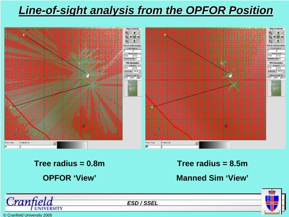
LineLine--ofof--sight analysis from the OPFOR Positionsight analysis from the OPFOR Position
Tree radius = 0.8m
OPFOR ‘View’
Tree radius = 8.5m
Manned Sim ‘View’
ESD / SSEL
© Cranfield University 2005
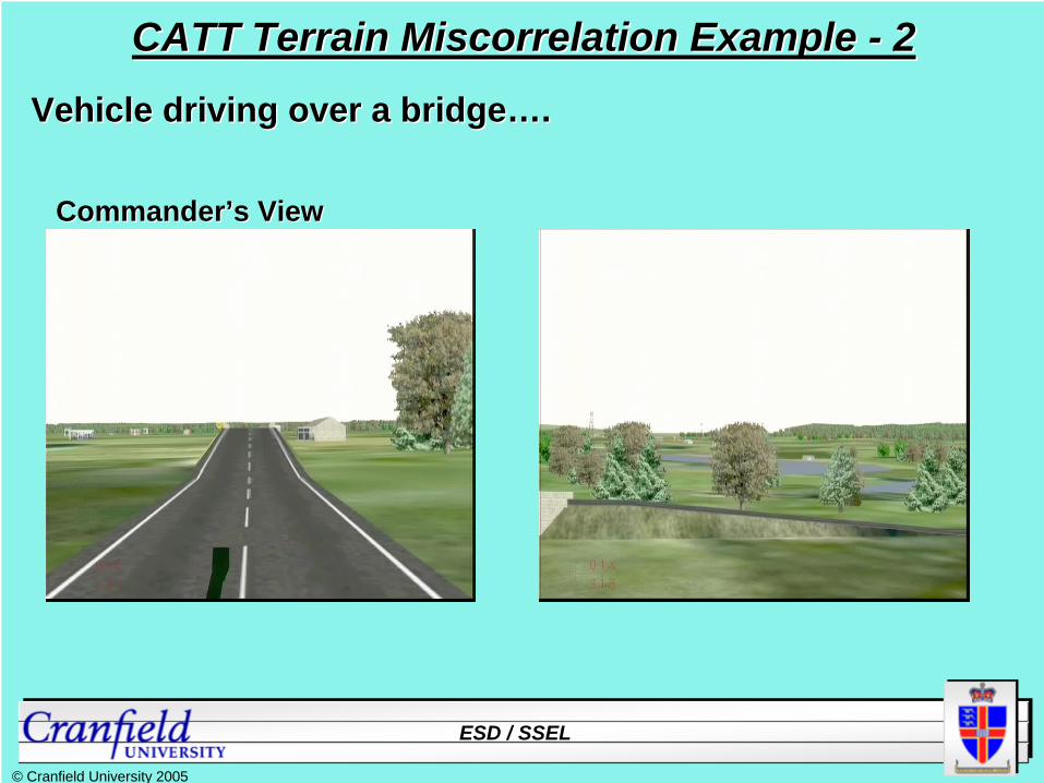
CATT Terrain Miscorrelation Example CATT Terrain Miscorrelation Example -- 22
Vehicle driving over a bridgeVehicle driving over a bridge……..
Drivers ViewDrivers View
CommanderCommander’’s Views View

ESD / SSEL
© Cranfield University 2005
Feature Difference in CATT Visual and Dynamics DataFeature Difference in CATT Visual and Dynamics Data
Vertical gap in road
Each CATT Simulator uses 3 separate terrain databases:Each CATT Simulator uses 3 separate terrain databases:Visual database (optical & thermal, etc)Visual database (optical & thermal, etc)Dynamics databaseDynamics databaseRadio propagation databaseRadio propagation database

ESD / SSEL
© Cranfield University 2005
TTSL / LM Database Study for MoD 1998TTSL / LM Database Study for MoD 1998[1998] Over £1billion will be spent by MoD on training systems over the next 5 yearsOver £30 million of this will be on simulation databasesHigh level of duplicated content
Geographic areas 79% duplicationAirfields 41% duplicationHigh detail areas 18% duplication
Databases are procured as part of the simulation system
Cost hidden in system costCommonality of requirements across systems is not addressed
Impact of re-use standards (eg SEDRIS)
ESD / SSEL
© Cranfield University 2005
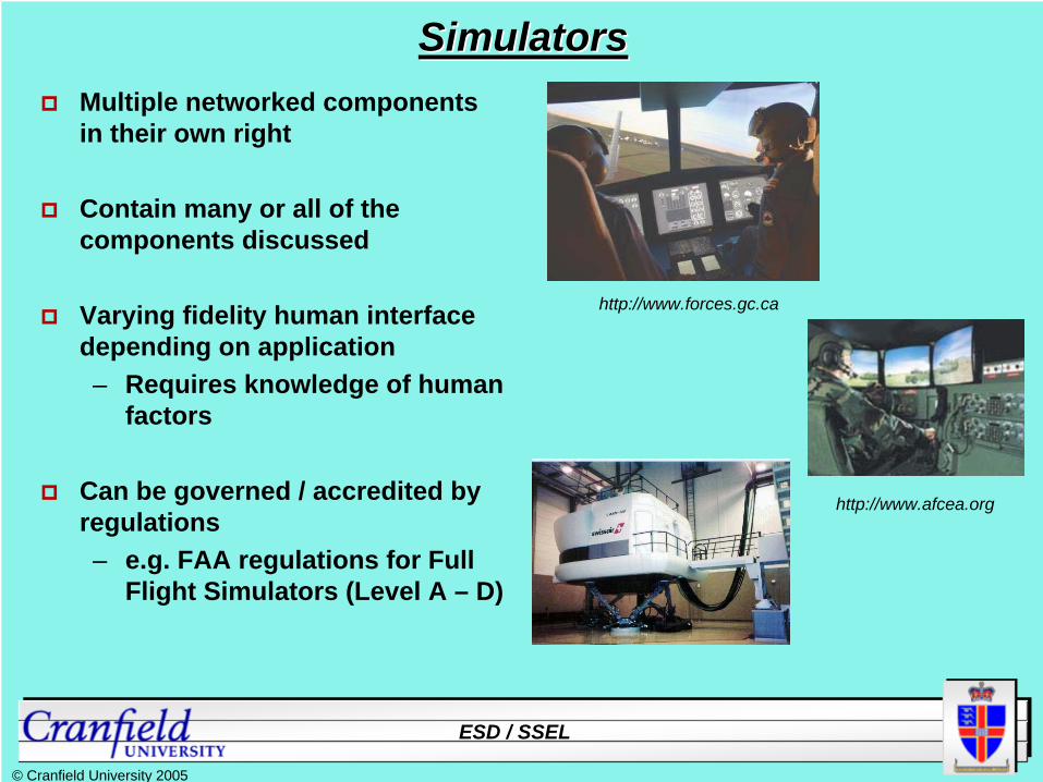
SimulatorsSimulatorsMultiple networked components in their own right
Contain many or all of the components discussed
Varying fidelity human interface depending on application– Requires knowledge of human
factors
Can be governed / accredited by regulations– e.g. FAA regulations for Full
Flight Simulators (Level A – D)
http://www.forces.gc.ca
http://www.afcea.org

ESD / SSEL
© Cranfield University 2005
Standards Standards -- DIS DIS vsvs HLAHLADIS: (IEEE Standard 1278)•
A communications protocol for information exchange between simulation applications.
•
DIS standard defines data transfer formats plus coord.systems, units, etc.
•
Ad-hoc interoperability process.
•
Data exchange is by fixed format, whole PDUs, broadcast best-effort between simulators.
•
Designed for real-time, platform level simulations and simulators. The aim is to create technical interoperability.
•
Originated in the training domain, with a heavy dependence on man-in the-loop systems. Exact accuracy (causality) is less important than general plausibility.
HLA: (IEEE Standard 1516)•
Formal process to design, develop, document and execute federations.
•
User-defined units, meaning, etc per- federation (FOMs & SOMs)
•
Auditable interoperability process, with supplied tools to assist (and thus also enhance/enforce) conformance.
•
Not reliant on fixed PDUs, individual data attributes sent by RTI between federates.
•
Allows for both time-synchronised & unsynchronised data transfer, real-time or faster or slower or mixture.
•
Support a broad range of federation types and create opportunities for component re- use (composability) across best-effort training federations (like DIS) and causally correct, engineering federations.

ESD / SSEL
© Cranfield University 2005
FEDEP FEDEP -- Federation Development and Execution ProcessFederation Development and Execution Process
[IEEE 1516.3]

ESD / SSEL
© Cranfield University 2005
Rep
osito
ryAnalyse User’s Needs
Define Fed. User Requirements
Define Fed. System Requirements
Design Federation
Implement Federation
Integrate & Test Federation
Operate Federation
Perform Evaluation
Analysis Documents
User Requirements Documents
System Requirements Documents
Design Documents
Federation Components
Federation ready for Execution
Federation Execution Outputs
Evaluation Results
EUCLID 11.13 EUCLID 11.13 –– SEDEP Concept DefinitionSEDEP Concept Definition
SEDEP : Synthetic Environment Development and Exploitation Process

ESD / SSEL
© Cranfield University 2005
Simulation ManagementSimulation ManagementConcept
Design
Development
Testing
Execution
Integration
Simulation management elements have parallels with systems engineering processes thus there is a logical interconnection between simulation realm and the real world.Thus the concepts of SeBA and Through Life Simulation Support were generated.
Software engineering processes have matured, aligning with some of the more common systems engineering processes.
Simulation management within this realm is more focused and specialized, dealing directly with integration and interoperability issues.

ESD / SSEL
© Cranfield University 2005
ThroughThrough--Life Simulation SupportLife Simulation SupportInitially use of simulation was “stove-piped”Cross-discipline collaboration introduced– Concept of Integrated Project Teams
Current technology and processes enable this– In M&S realm– Between M&S realm and real world
CD&E SeBA M&S in T&EDMTDMOMR
AnalysisAAR

ESD / SSEL
© Cranfield University 2005
Simulation Enhanced/Supported CapabilitySimulation Enhanced/Supported CapabilityIn the past defence organizations were threat focused
Today most defence organizations are capability focused
Much like efforts to use and reuse models and simulations in thedevelopment, acquisition and employment of equipment, M&S can be applied to the life cycle of a capability
One vehicle that can assist in this effort is the concept of a simulation support plan– Living documents that assess, identify and describe the use
and management of M&S in capability generation
ESD / SSEL
© Cranfield University 2005
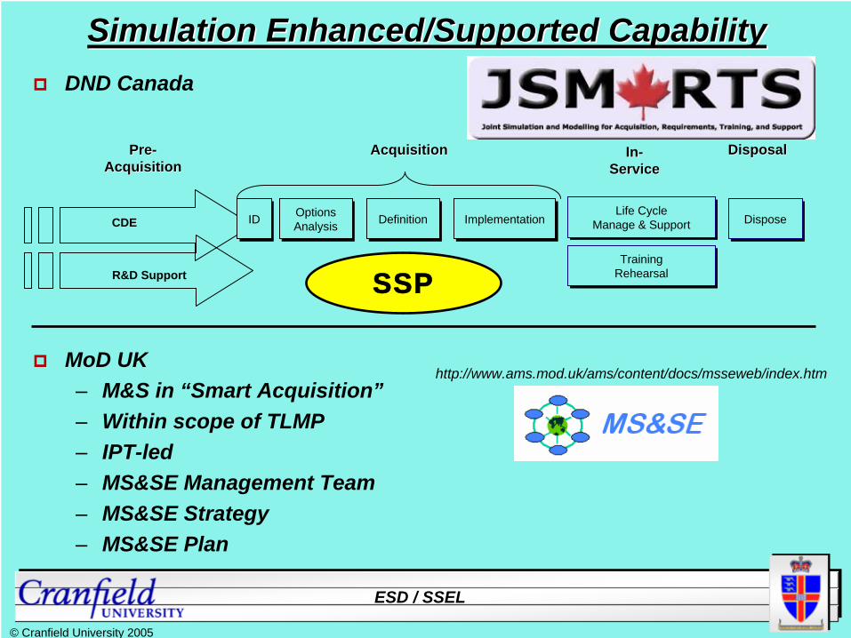
Simulation Enhanced/Supported CapabilitySimulation Enhanced/Supported CapabilityDND Canada
MoD UK– M&S in “Smart Acquisition”– Within scope of TLMP– IPT-led– MS&SE Management Team– MS&SE Strategy– MS&SE Plan
CDE
R&D Support
IDID Options Analysis Options Analysis DefinitionDefinition ImplementationImplementation Life Cycle
Manage & Support Life Cycle
Manage & Support
PrePre-- AcquisitionAcquisition
AcquisitionAcquisition InIn-- ServiceService
DisposalDisposal
TrainingRehearsalTraining
Rehearsal
DisposeDispose
http://www.ams.mod.uk/ams/content/docs/msseweb/index.htm
SSP

ESD / SSEL
© Cranfield University 2005
SummarySummaryThe use of simulation has grown significantly over the past few decades
Components in any given simulation activity can be numerous
Technology growth has enabled connectivity
Maturing processes have enable collaboration
Simulation and real world activities have become complementary
This requires dedicated and deliberate focus on interoperabilityand integration
Simulation activities must be managed in parallel throughout thelife cycle of a capability or system

ESD / SSEL
© Cranfield University 2005
Questions / DiscussionQuestions / DiscussionMr. Jonathan Searle
Manager, SSELDefence Academy
Cranfield University+44 (0)1793 785852
Mr. John BrennanLecturer, Defence Simulation
Defence AcademyCranfield University+44 (0)1793 785464
http://www.rmcs.cranfield.ac.uk/ssel