simposium nasional iatmi 2009 · simposium nasional iatmi 2009 ... makalah professional iatmi...
TRANSCRIPT

IATMI 09 032 1
IKATAN AHLI TEKNIK PERMINYAKAN INDONESIA
Ikatan Ahli Teknik Perminyakan Indonesia
Simposium Nasional IATMI 2009
Bandung 2-5 Desember 2009
Makalah Professional
IATMI 09-032
Improving ESP Run Life thru Application of Recycle System:
A Shared Story from the Second Installation of Recycle System
On Umainah D-05, South East Sumatra Block
By Andromeda, Wimbuh Nugroho, Andi Rangga
CNOOC SES Ltd.
Abstract
Most oil well located in South East Sumatra block is ESP artificially lifted. Within ESP, there is a recommended operating capacity range to be operated efficiently. Production interruption is occurred whenever the well is producing outside this recommended range. The problem may get worse; if there is no appropriate ESP available, making ESP operated below its recommended range, and eventually gets pump-off. Not all ESP can be restarted smoothly after having tripped, especially for the well whose sand / scale problem. The basic idea is how to make ESP runs within / close to its recommended operating capacity range; one of method to achieve this objective is application of recycle system.
To achieve the objective, ESP must be operated within recommended operating capacity of range. If the fluid from formation flowing to ESP is insufficient meaning there must be another fluid as an additional source to make ESP is operated within recommended range. The basic mechanism of the recycle system is utilizing some of surface producing fluid to be diverted back in to the well thru a flexible hose connected from tubing hanger to the production packer. This diverted back fluid goes to ESP and mixed with the formation fluid and produced together to surface and get diverted back again.
Observation will focus on ESP amp-chart and production data, which indicate the effectiveness of this recycle system
After the recycle system was applied, ESP run life increased from 70 days to 620 days prior getting DHP on December 2008. After completing the second installation, currently ESP still run smoothly and gives continuous oil production. Based on the amp-chart trend and production data, it may be concluded that the recycle system makes a contribution in minimizing production interruption due to ESP running below recommended operating capacity range ESP, thus prolong ESP run life.
Introduction
CNOOC has been operating more than 400 wells on the South East Sumatra block since 2002, mostly equipped with Electrical Submersible Pumps (ESP). ESP has an optimum efficiency when it is being operated between its recommended operating capacities range indicating by the continuous presence of sufficient fluid level inside wellbore; otherwise ESP potentially has a shorter run life compared to its target run life. This continuous presence of sufficient fluid level inside wellbore relates to reservoir ability to

IATMI 09 032 2
supply fluid for the ESP and is also influenced by the near wellbore condition, including perforation tunnel. Each ESP installed is determined by the expected fluid rate.
Reservoir ability will decline when the pore pressure is decreased during the life of the well, mostly named reservoir pressure decline. Pore pressure is decreased when the fluid stays inside the pore is produced out. If the reservoir mechanism is water drive / strong water drive the decline will be slower compared to other reservoir driving mechanism. Reservoir ability will decline also when there is a near wellbore damage so that the fluid supply flowing to ESP is reduced than it s supposed to be. Further, both of them affect ESP performance.
In ESP point of view, although reservoir ability is still sufficient enough to feed ESP by flowing sufficient fluid, ESP performance could be below expectation or outside its recommended capacity range when there is a flow restriction on ESP vicinity. The flow restriction may cause ESP running, both on under load or over load mode. The mostly causes for the first cases occurred when intake gets plugged and for the second cases occurred when sand flow thru the pump and scale build up inside the pump.
Umainah field is produced from Talang Akar Formation (TAF) sandstone at an average depth of 7000 TVD, and production ranges from 200-2000BFPD. Umainah field has six platforms consists of Umainah A, B, C, D, E, and F. The subjected well is located on Umainah D platform, which has oil well and gas well. Umainah D-05 itself is an oil well. This is a second installation of recycle system. Based on the history, scale is the major problem that causes ESP run below its performance thus ESP failure. The combination of a low production rate, which increases ESP operating temperature, and high reservoir temperatures contribute to increased scale buildup tendencies of the water produced. Scale is present at the perforation tunnel and intake & pump section of ESP. Scale from this well is of a Calcium Carbonate type (Lemigas, 1991). In oil wells, calcium carbonate precipitation is usually caused by a pressure drop, releasing CO2 from bicarbonate ions. When CO2 is released, the pH increases, the solubility of dissolved carbonates decreases, and the more soluble bicarbonate is converted to less soluble carbonates (Allen & Roberts, 2004)
Scale Combat for Perforation Tunnel Before Recycle system applied, several scale
combat methods applied to handle the scale build up. Some of them worked properly with some limitations and some of them gave unexpected result. Scale combat into the perforation tunnel is executed by utilizing a stimulation packer. This packer is needed as a separation for one interval perforation to another. It is
expected that by separating the exist interval, the injected scale inhibitor can go through and react inside in each interval. If a stimulation packer is not utilized, there will be the possibility that the scale inhibitor pumped will go into perforations with higher permeability; thus not all perforations get treated. If this happens, the scale formed inside untreated perforation tunnels will prevent fluid flow, thus reducing the fluid rate and affecting ESP performance. Scale combat, by pumping scale inhibitor into the perforation tunnel, yields various results. Several wells show an improvement of ESP run life and others reveal opposite results. For scale combat results that failed to meet expectations, it is suspected that scale did not enter perforation tunnel
signifying successful treatment
but rather ended up in the ESP environment.
Scale combat into perforations is also executed by pumping scale inhibitor down through a Sliding Sleeve Door (SSD) of the tubing. This method is much cheaper than scale combat using a stimulation packer, but since there is the possibility that the pumped scale inhibitor only goes through to perforations with higher permeability, this method is only implemented at wells with a single perforation. This method is relatively cheaper since we do not need to pull and run strings, but the penetration of the scale inhibitor won t be as deep as scale combat, using a stimulation packer.
Scale Combat for ESP Vicinity Other scale combat applied includes a
continuous injection scale inhibitor using ¼ stainless tube to the bottom of ESP. All installations of this system failed due to precipitation of the scale inhibitor, in both the injection tube and the pump (Kusumamulya, 1998). One explanation for this failure was the absence of any water analysis prior to injecting the scale inhibitor and because of this, there is the possibility that the scale inhibitor injected did not matched the water property formation, and indeed contributed to a scale build-up tendency.
Pre & Post Recycle System Application ESP run life, prior installing recycle system on
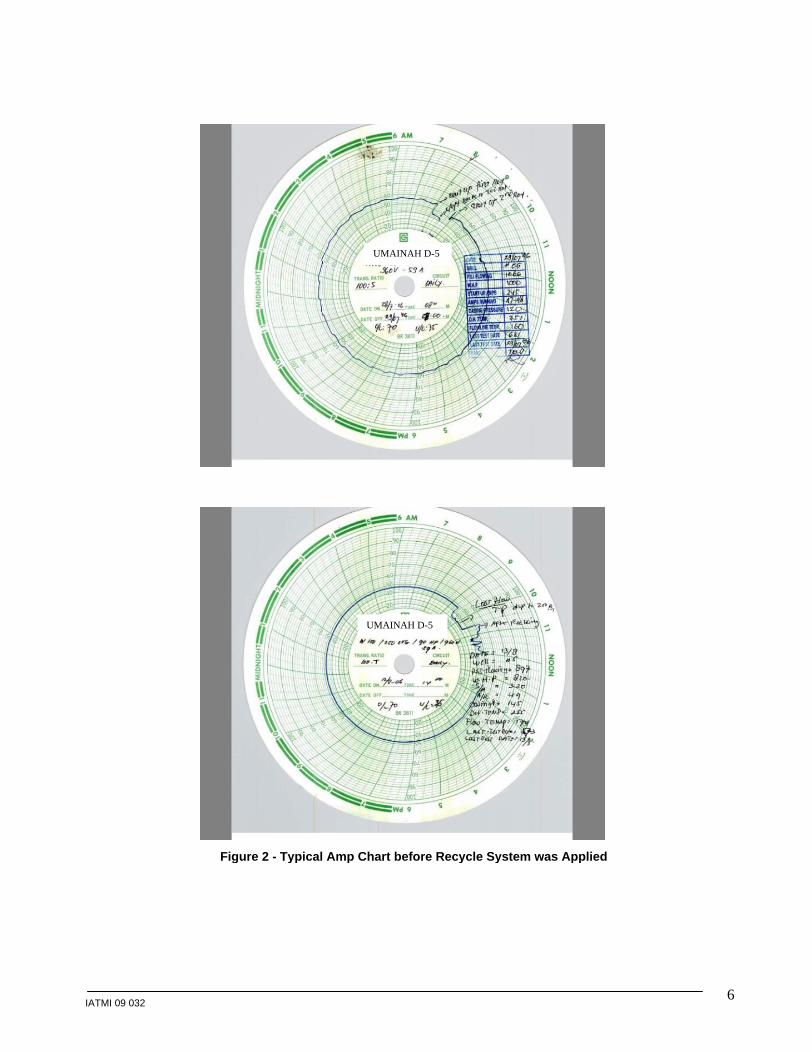
this well was 70 days. 70 days run live was achieved after scale combat only focused into perforation only. Based on findings on amp chart, it is suspected that scale already built up across pump section and made ESP rotation became rough. In other words, this rough rotation leads to insufficient fluid that could be drained by ESP. Therefore, ESP ran below its recommended capacity range. Further, this condition made motor worked heavier that its proper load, thus ESP got DHP
The latest scale combat utilized on this well is a recycle system. The first recycle system installation at Umainah D-05 was in Dec 2006. After installation the ESP ran smoothly, as can be viewed from its

IATMI 09 032 3
typical amp-chart before (Figure 2) and after the recycled system was applied (Figure 3). After first installation of recycle system, ESP run life increased to 620 days. It shows that scale combat could work as well as expected. This was also supported by the Phosponate Residual Content data (please refer to method section for detail), which showed concentration above 1ppm (Figure 4). Since during Aug 2008, there were no records taken for PRC, so that the scale inhibitor performance was not observed and there was possibility of slow scale buildup at ESP (Andromeda, 2009)
This paper discusses second installation of recycle system at Umainah D-05. Refer to previous installation; scale combat was exposed not only to the perforation tunnel but also to ESP. ESP can run smoothly, as observed from the amperage chart. The corrective action to the first installation is a punctual PRC monitoring to prevent no record taken in particular period of time on previous installation. PRC is monitored weekly to gather information how effective the scale inhibitor works.
Method Objective of recycle system is to add several
amounts of fluid injected back into the well. It is expected this injected fluid is able to add and/ maintain the fluid level above the intake. With this additional support, ESP operating under a recommended rate range could be assisted to encourage smoother running. Beside that, recycle system is also able to be utilized to inject scale inhibitor down the well thru annulus. The basic practice of the recycle system is mixing the scale inhibitor with several produced fluids prior to injecting them into a well. With this system, the pressure of fluid coming out of the well is used as a driver to inject through annulus. A tee connection with a choke is installed in the production line between the wellhead and the test separator. The choke is adjusted such that a portion of the produced fluid is diverted through the recycle loop and back into the well. As the fluid passes through the recycle loop, a scale inhibitor is added; the produced fluid is then injected down the annulus through 1 flexible hose. Almost all wells at CNOOC are equipped with packers. 1 flexible hose is run from the tubing hanger to the packer. Below the packer, the mix fluid-inhibitor will flow down and enter the ESP through the intake, then the pump section (Figure 1).
Samples of produced fluid mixed with scale inhibitor are taken and Phosphonate Residual content (PRC) is measured. Based on PRC concentration, we can determine scale inhibitor performance in preventing scale build-up. Based on Lab tests held by the scale inhibitor provider, it is known that the minimum PRC is 1ppm. Scale inhibitor does not react with formation fluid. It only covers and wets the fluid particles. Through this cover, the tendency for scale
build-up from water produced is minimized. PRC shows smaller than 1ppm indicates that the presence of scale inhibitor injected downhole is no longer sufficient to cover the fluid particle thus, an increased injection rate is needed at the surface
Result and Discussion The second installation of recycle system on
Umainah D-05 was completed at October 11, 2008. Prior ESP installed, scale combat was conducted by pumping scale removal into perforation. Since ESP start up, amp chart showed a smooth trend like similar trend on previous installation (Figure 5).
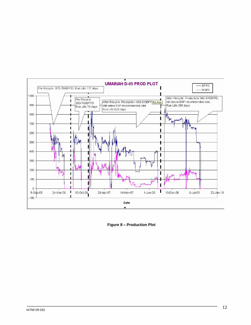
To put ESP running closes to optimum efficiency, ESP has to drain fluid within recommended capacity range. On first and second recycle system installation, the ESP was DN 1750. As per reference, this ESP recommended capacity range is 1200-200BFPD. Referring to production plot, we may observe that the fluid rate is still below the lowest capacity recommendation, the fluid rate played around 400-870BFPD (Figure 8). There is a slightly increased rate between generated by ESP between first and second installation of recycle system.
As a corrective action for first installation, on second installation PRC data is monitored regularly to achieve brief description as an indicator of scale inhibitor performance. During monitoring, it is know that PRC always above 1ppm, meaning the amount of scale inhibitor covering and wetting the liquid particle from scale build up is still sufficient (Figure 6).
ESP still ran smoothly as represented by the amp chart. Both first and second installation showed a significant increased rate generated by ESP compared to pre recycle system installation. Almost for one year ESP run smoothly showing that recycle system and all of its components worked properly in line with expectation.
Recycle system directly correlates with ESP operation under its recommended capacity range. This recommended capacity belongs to liquid rate, instead oil rate. We know that ESP design is generated based on total liquid rate which is consisted of water and fluid rate. It is by assumption that ESP gas handling is achievable by flowing gas to surface altogether with liquid without any restriction to production.
On August 29, 2009 ESP got tripped Over Load with good cable reading (P-P: 2.6ohm and P-G: 5Mohm). Referring to cable reading which is still good, it is suspected that problem comes from mechanical or well; shaft rotation seems to be rough. As a troubleshooting, ESP was tried to be restarted by VSD with various frequency and mode but it was still failed to put the well back on line. Other effort is by flushing ESP by formation fluid from its adjacent well, after

IATMI 09 032 4
check valve retrieved, but there was no backspin found. Both troubleshooting gave similar result. Based on both, min suspect tends to scale build up, instead electrical. Since PRC is monitored regularly, a question raised why scale built up inside pump.
Further review, on August 20, 2009 there was a sub sea pipe line leaking connecting Umainah A
Umainah E Platform and nine days after that Umainah D-05 tripped OL. The consequence of this leaking pipe line is Umainah D-05 has to be SI for a whole days. There is possibility scale built up during SI. After this leaking handled, Umainah D-05 could be restarted again but from the amp chart we might observed erratic / spike trend began appeared during ESP ran (Figure 7). Total SI was 3 days including waiting for sub sea pipe line leaking repair and waiting for VSD & SL unit arrived on platform.
At the system, which runs on normal circumstance, scale build up may be prevented because scale inhibitor wets and covers the liquid particle during flowing from ESP to surface. But at the system interrupted, at this case well SI and ESP off, concentration of PRC thru recycle system cannot be exactly determined to prevent scale build up since there could be scale formed. Even after SI, ESP could be restarted back but the remaining scale inhibitor injection only seems only cured the potential scale build up instead scale that already deposited inside pump. At this condition, we assume scale built up that deposited inside pump section during well SI, could not be removed by the scale inhibitor Thus, making ESP running is shorter than first installation.
Although fluid rate is still below recommended capacity range ESP ran smoothly DN 1750 may be utilized again because this ESP is a mixed flow type and the distance between impeller and diffuser is wider than other ESP available for this typical fluid rate. By these advantages, in case there is a soft material flow thru pump, it will deliver the material to surface as long as the continuous flow condition is achieved.
For next installation to improve ESP run life, study for the type of chemical utilized as scale combat might be taken into consideration. For instance, when there is a continuous flow scale inhibitor will be injected thru recycle system. But, if the well must be SI or SO (pipe line leaking, power outage, tripped OL/UL), scale removal will be injected thru recycle system for several period of time to remove the deposited scale inside pump. After ESP rotation get smoother, observing form the amp chart, scale inhibitor will be injected again.
Conclusion Based on experience gathered during from the
second installation of recycle system:
1. The typical amp-chart revealed smooth ESP operation after second installation of recycle system. It is similar with the first installation
2. PRC monitoring is conducted regularly punctual to prevent similar problem happened on first installation
3. Run life decline contributed by factor outside recycle system. On this shared story, run life decline contributed by well SI due to pipe leaking
4. If the well has to be SI, amount of scale inhibitor injected is different with continuous flow. The similar treatment could not make the well running like previous
Recommendation 1. For next installation, similar size and type ESP
might be utilized again since it has advantages compared to other types available
2. Keep PRC data monitoring regularly and punctual to avoid lack of scale inhibitor covering the liquid particle
3. Conduct study for other option for scale combat utilized in case well has to be SI
4. Improved pipe line durability connecting platform whose well with scale problem
Acknowledgment I wish to thank IATMI professional paper committee for allowing me to publish this paper. I would like to my appreciation for Central District engineers who already inspire me to write this paper and. Also, I send grateful thanks to the Central District Manager and Central District offshore staff that support and provide supporting data to complete this paper.
References
1. Allen, Thomas & Roberts, Alan. 2004. Production Operation 2. OGCI and PetroSkills Publication
2. Andromeda. 2009. Application of recycle system to inhibit scale deposition and plugging inside ESP. IPA 09036
3. Central District. 2006-2009. Amp Chart of Umainah D-05. CNOOC SES Ltd.
4. Central District. 2009. Chemical Status Report CBU. CNOOC SES Ltd.
5. Central District. 2009. ESP POH Report CBU. CNOOC SES Ltd.
6. Central District. 2009. Well Diagram CBU. CNOOC SES Ltd.
7. Kusumamulya, Kurnia. 1998. Recycle System to extend ESP Run Life (Short Story). Maxus SES Inc.
8. LEMIGAS. 1991. XRD, SEM, and EDAX. Maxus SES Inc

IATMI 09 032 5
Figure 1 - Typical Recycle System Configuration
IATMI 09 032 6
UMAINAH D-5
UMAINAH D-5
Figure 2 - Typical Amp Chart before Recycle System was Applied

IATMI 09 032 7
UMAINAH D-5
UMAINAH D-5
UMAINAH D-5
Figure 3
-
Typical Amp Chart on First Recycle System Installation

IATMI 09 032 8
Month : November-08
PRC CONTENT (PPM)
Well PARAMETER
3-Nov-
08
10-Nov-
08
17-Nov-
08
24-Nov-
08
1-Dec-08
8-Dec-08
UMAINAH D-5
PRC min 1ppm
2.4 2.2 4.3 3.8
Figure 4
Phosponate Residual Content on First Installation

IATMI 09 032 9
Figure 5
-
Typical Amp Chart on Second Recycle System Installation

IATMI 09 032 10
Month : August-09
PRC CONTENT (PPM)
Well PARAMETER
3-Aug-
09
10-Aug-
09
17-Aug-
09
24-Nov-
09
01-Sep-09
08-Sep-09
UMAINAH D-5
PRC min 1ppm
2.4 3.2 3.4 3.0 - -
Figure 6
Phosponate Residual Content on Second Installation

IATMI 09 032 11
Figure 7
Amp Chart ESP restarted after SI after SS Pipeline Leaking
IATMI 09 032 12
Figure 8
Production Plot

This document was created with Win2PDF available at http://www.daneprairie.com.The unregistered version of Win2PDF is for evaluation or non-commercial use only.