simplorer getting started guide - url.t gsg r182.pdf · tableofcontents tableofcontents contents-1...
TRANSCRIPT

Simplorer Getting Started Guide
ANSYS, Inc.Southpointe2600 ANSYS DriveCanonsburg, PA [email protected]://www.ansys.com(T) 724-746-3304(F) 724-514-9494
Release 18.2 July 2017
ANSYS, Inc. andANSYS Europe,Ltd. are ULregistered ISO9001:2008 com-panies.

Simplorer Getting Started Guide
Copyright and Trademark Information
© 2017 ANSYS, Inc. Unauthorized use, distribution or duplication is prohibited.
ANSYS, ANSYSWorkbench, Ansoft, AUTODYN, EKM, Engineering KnowledgeManager, CFX,FLUENT, HFSS and any and all ANSYS, Inc. brand, product, service and feature names, logosand slogans are registered trademarks or trademarks of ANSYS, Inc. or its subsidiaries in theUnited States or other countries. ICEMCFD is a trademark used by ANSYS, Inc. under license.CFX is a trademark of SonyCorporation in Japan. All other brand, product, service and featurenames or trademarks are the property of their respective owners.
Disclaimer Notice
THIS ANSYS SOFTWARE PRODUCT AND PROGRAMDOCUMENTATION INCLUDETRADE SECRETS AND ARE CONFIDENTIAL AND PROPRIETARY PRODUCTS OFANSYS, INC., ITS SUBSIDIARIES, OR LICENSORS. The software products and doc-umentation are furnished by ANSYS, Inc., its subsidiaries, or affiliates under a software licenseagreement that contains provisions concerning non-disclosure, copying, length and nature of use,compliance with exporting laws, warranties, disclaimers, limitations of liability, and remedies, andother provisions. The software products and documentationmay be used, disclosed, transferred,or copied only in accordance with the terms and conditions of that software license agreement.
ANSYS, Inc. is certified to ISO9001:2008.
U.S. Government Rights
For U.S. Government users, except as specifically granted by the ANSYS, Inc. software licenseagreement, the use, duplication, or disclosure by the United StatesGovernment is subject to restric-tions stated in the ANSYS, Inc. software license agreement and FAR 12.212 (for non-DODlicenses).
Third-Party Software
See the legal information in the product help files for the complete Legal Notice for ANSYS pro-prietary software and third-party software. If you are unable to access the Legal Notice, please con-tact ANSYS, Inc.
2
Simplorer 18.2 - © ANSYS, Inc. All rights reserved. - Contains proprietary and confidential
information of ANSYS, Inc. and its subsidiaries and affiliates.

Table of ContentsTable of Contents Contents-1
1 - Introduction 1-1
Overview of the Simplorer Interface 1-1
2 - Creating a New Project 2-1
About the Three-Phase Rectifier 2-1
Expected Results 2-2
Using Simplorer to Create and Improve the Design 2-3
Creating the New Project 2-4
Add the New Project 2-4
Rename the Design 2-5
Add Design Notes (Optional) 2-6
Save the New Project 2-6
3 - Create the Rectifier Model 3-1
Create the Three-Phase Rectifier Schematic 3-1
Choosing, Placing, and Arranging Components on the Schematic Sheet 3-2
Connecting the Components 3-8
Defining Component Properties 3-8
Property Displays for Components 3-11
Specifying Simulation Outputs 3-15
Defining Solution Options and Analysis Parameters 3-17
Starting an Analysis 3-18
Plotting Rectifier Model Simulation Results 3-19
4 - Hysteresis Current-Controlled DC-Motor Start-Up 4-1
Modify the Rectifier Model Design 4-1
Deleting the Resistive/Inductive Load 4-2
Saving the Sheet with a New Name 4-2
Simplorer Getting Started Guide
Contents-1
Simplorer 18.2 - © ANSYS, Inc. All rights reserved. - Contains proprietary and confidential
information of ANSYS, Inc. and its subsidiaries and affiliates.

Simplorer Getting Started Guide
Defining DC Machine Values 4-3
DefiningMechanical Load 4-4
Freewheeling Diode 4-5
Chopper Transistor 4-5
Controller Modeling Using Block Elements 4-7
Modifying Report Elements 4-9
Display Diode Characteristic 4-9
Defining Simulation Parameters 4-11
Starting Simulation (BlockComponents) 4-11
Simulation Results (BlockComponents) 4-11
Controller Modeling Using State Graph Components 4-12
Connecting the State Graph Components 4-13
Defining the Properties of State Graph Components 4-13
Using NameReferences 4-16
Deactivating Components on the Sheet 4-16
Starting Simulation (State Graph) 4-18
5 - Current and Speed Controlled DC Motor 5-1
Modify the State Graph Design 5-1
Deleting the State Graph 5-2
Saving the Sheet with a New Name 5-3
DefiningMechanical Load (Block) 5-4
Defining the PI Controller 5-6
Starting Simulation 5-9
Adding a Rectangular Plot (PI Controller) 5-9
Adjusting Plot Properties 5-11
Checking the Block Sequence 5-12
Using Automatic Block Sorting 5-13
UsingManual Block Sorting 5-13
Contents-2
Simplorer 18.2 - © ANSYS, Inc. All rights reserved. - Contains proprietary and confidential
information of ANSYS, Inc. and its subsidiaries and affiliates.

Simplorer Getting Started Guide
Rerun the Simulation (PI Controller) 5-14
Simulation Results (PI Controller) 5-14
6 - Using VHDL-AMS Components for Modeling 6-1
VHDL-AMS Components 6-1
Modify the PI Controller Design 6-1
Save the Project with a New Name 6-2
Delete the DC Machine Component 6-3
Placing and Arranging the New VHDL-AMS Components on the Sheet 6-3
Connecting the New VHDL-AMS Components 6-3
Defining VHDL-AMS DC Machine Values 6-3
Defining Connections for Machine Current 6-4
Defining Simulation Parameters 6-5
Analyze and Display Simulation Results (VHDL-AMS) 6-5
7 - Variants of PWM Modeling 7-1
PWMModeling Overview 7-1
Create a New Project for the PWMModels 7-2
Setting Initial Conditions 7-2
PWMModeling Using Equations 7-3
Defining Simulation Parameters 7-3
Displaying Simulation Results with Reports 7-4
Simulation Results 7-4
PWMModeling with Equations and Time Function 7-5
PWMModeling with State Graph Components 7-6
Place and Arrange the Components on the Sheet 7-7
Define Component Properties 7-7
PWMModeling with BlockDiagramComponents 7-9
Placing and Arranging the Components on the Sheet 7-9
8 - Using Legacy Schematics 8-1
Contents-3
Simplorer 18.2 - © ANSYS, Inc. All rights reserved. - Contains proprietary and confidential
information of ANSYS, Inc. and its subsidiaries and affiliates.

Simplorer Getting Started Guide
Translating a Legacy Schematic using Release 16.2 or Earlier 8-2
Importing the Legacy Schematic into Simplorer Release 16 or earlier 8-2
Opening the Translated Schematic in Simplorer 2017.1 or Later 8-7
Starting an Analysis 8-8
Plotting Simulation Results 8-9
Index Index-1
Contents-4
Simplorer 18.2 - © ANSYS, Inc. All rights reserved. - Contains proprietary and confidential
information of ANSYS, Inc. and its subsidiaries and affiliates.

1 - IntroductionThisGetting Started guide is written for Simplorer beginners aswell as experienced users who areusing Simplorer for the first time.
Simplorer is a simulation package for multi-domain designs that are commonly found in automotive,aerospace, power electronics, and electric drive systems.
Simplorer provides an approach for the virtual prototyping of large-scale systems by letting you todevelop a design that combines predefined basic and industry-specific components with user-definedmodels. You can createmodels in common programming languages or standardmodelinglanguages such as VHDL-AMS. The basic and industry-specificmodel libraries available for Sim-plorer provide ready-to-use parameterized components, making Simplorer accurate, and flexible.
l Chapter 2 of this guide shows you how to create and save a new Simplorer project.l Chapter 3 leads you step-by-step through creating, solving, and analyzing the results of aThree-Phase Rectifier.
l Chapter 4modifies the example of Chapter 3 by replacing the resistive/inductive load witha real machinemodel. The example is then expanded to include a control circuit modeledfirst using discrete components, then using state graph components.
l In Chapter 5 the state graph controller is replaced with a PI (proportional-integral) con-troller implemented using block components.
l Chapter 6 substitutes the use of VHDL-AMS opponents for modeling the DC motor.l Chapter 7 explores several different methods for modeling a PWMController to demon-strate Simplorer’s versatile modeling capabilities.
l Chapter 8 leads you through the process of importing a legacy Simplorer 7 Three-PhaseRectifier schematic into Simplorer Release 16.2, saving it, migrating it into Simplorer2017.2, and then solving and analyzing the translatedmodel.
Overview of the Simplorer InterfaceBelow is an overview of themajor components of the Simplorer interface.
Simplorer Getting Started Guide
Introduction 1-1
Simplorer 18.2 - © ANSYS, Inc. All rights reserved. - Contains proprietary and confidential
information of ANSYS, Inc. and its subsidiaries and affiliates.

Simplorer Getting Started Guide
Project Man-ager win-dow andProject Tree
The Project Manager window shows all the components, models, and other ele-ments of each design in the project. Each project has its own expandableProjectTree. Many operations on the design elements can be performed directly from theProject Manager window.
MessageManagerwindow
Displays error, informational, and warningmessages for the active project.
Progresswindow
Displays solution progress information.
Introduction 1-2
Simplorer 18.2 - © ANSYS, Inc. All rights reserved. - Contains proprietary and confidential
information of ANSYS, Inc. and its subsidiaries and affiliates.

Simplorer Getting Started Guide
Propertieswindow
Displays the attributes of a selected object in the activemodel, such as the object’sname, electrical or other associated physical quantities, orientation, and color.
Also displays information about a selected command that has been carried out.For example, if a circle was drawn, its command information would include thecommand’s name, the circle’s center position coordinates, and the size of itsradius.
Design areawindow
Displays one or more editor windows such as the Schematic Editor, model editors,and symbol editor. It also displays various report windows.
ComponentLibrarieswindow
Displays, on the Components tab, the component categories, including Favorites,Most Recently Used, Simplorer Elements, and Project Components. You can pinthe window tomake it remain visible or make it visible only when it is being used.
The following elements are defined as favorites by default:
l R (resistor)l L (inductor)l C (capacitor)l D (diode)l E (voltage source)l AM (ammeter)l VM (voltmeter)
The Project Components section lists the elements that are active in your projects.
If you have created any personal libraries, a Personal Libraries section displaysthem.
The Component Manager window also provides a search feature on the Searchtab.
Menu bar Provides variousmenus that enable you to performSimplorer tasks, such asman-aging project files, designs, and libraries; customizing desktop components; draw-ing objects; and setting andmodifying project parameters and options.
Toolbars Provides buttons that act as shortcuts for executing various commands.
Status bar Shows current actions and provides instructions.
Introduction 1-3
Simplorer 18.2 - © ANSYS, Inc. All rights reserved. - Contains proprietary and confidential
information of ANSYS, Inc. and its subsidiaries and affiliates.

PDF layout 1-4
Simplorer 18.2 - © ANSYS, Inc. All rights reserved. - Contains proprietary and confidential
information of ANSYS, Inc. and its subsidiaries and affiliates.
Simplorer Getting Started Guide

2 - Creating a New ProjectThis guide assumes that you have installed Simplorer.
In this chapter you will complete the following tasks:
l Create and save a new project.l Add and rename a Simplorer design in the project.
About the Three-Phase RectifierThe following example describes a three-phase power supply and a rectifier bridge with res-istive/inductive load. For the input signals, time-controlled voltage sourceswill be used. The diodes,the capacitor, and the resistor are ideal components; the diodes are determined by an exponentialfunction (their characteristic).
Simplorer Getting Started Guide
Creating a New Project 2-1
Simplorer 18.2 - © ANSYS, Inc. All rights reserved. - Contains proprietary and confidential
information of ANSYS, Inc. and its subsidiaries and affiliates.

Simplorer Getting Started Guide
Expected Results
After the simulation is run, the results are displayed in Report windows. For example, the first sim-ulation variation demonstrates these results:
l Voltages of the sources ET1.V, ET2.V, and ET3.Vl Voltage of the smoothing capacitor CD.Vl Current of the load resistor R_LOAD.I
Creating a New Project 2-2
Simplorer 18.2 - © ANSYS, Inc. All rights reserved. - Contains proprietary and confidential
information of ANSYS, Inc. and its subsidiaries and affiliates.

Simplorer Getting Started Guide
Using Simplorer to Create and Improve the DesignAs you step through thisGetting Started guide, you will be introduced to several key concepts:
l There are numerousways to performmost tasks.
For example, several methods are presented for selecting and for assigning design para-meter values.
Creating a New Project 2-3
Simplorer 18.2 - © ANSYS, Inc. All rights reserved. - Contains proprietary and confidential
information of ANSYS, Inc. and its subsidiaries and affiliates.

Simplorer Getting Started Guide
l There is no required sequence of events when creating a design.— A convenient methodfor creating the three-phase rectifier will be demonstrated, but the design setup steps can becompleted in any logical order.
l You can quicklymodify design properties at any time.
For example, you can draw a box freehand, then specify its exact dimensions in theProp-ertieswindow.
l You can easilymanage your design in the project tree.
The branches of the project tree in theProject Manager window provide access to setupdialogs, where you canmodify design properties.
l You canmodify themodel view at any time.
Youwill learn shortcut keys likeCtrl+D, which fits themodel in the view window.
l You can save time by parameterizing design properties.
This enables you to quicklymodify design properties and generate new results.
l You can use Simplorer’s extensive post-processing features to evaluate solution results.
Creating the New ProjectThe first step in using Simplorer to solve a problem is to create a project in which to save all of thedata associated with the problem. A project is a collection of one or more designs saved in a single*.aedt file. By default, opening Simplorer creates a new project named Projectn and inserts a newdesign named Simplorern, where n is the order in which each was added to the current session.
Add the New ProjectTo add a new Simplorer project:
l ClickFile>New.
Creating a New Project 2-4
Simplorer 18.2 - © ANSYS, Inc. All rights reserved. - Contains proprietary and confidential
information of ANSYS, Inc. and its subsidiaries and affiliates.

Simplorer Getting Started Guide
A new project named Projectn containing a new design named Simplorern is added in theproject tree in theProject Manager window.
Hint l If the Project Manager does not appear, clickView>Project Manager.l If a new design does not appear automatically, clickTools>Options> GeneralOptions. Under Project Options, select Insert a design of type.
l To automatically expand the project tree when an item is added to the project, clickTools>Options> General Options. Under Project Options, selectExpand Pro-ject Tree on Insert.
The new project contains a file structure that organizes design elements such as: Ports, Ana-lysis, Optimetrics, and Results. Project Definitions such asComponents, Symbols, Models,Packages, Materials, and Scripts are also listed.
Rename the DesignYou can rename the default Simplorer design name as follows:
1. Right-click Simplorern in the project tree, and chooseRename on the shortcut menu. Youcan also click the name to select it, then pressF2.
This enables the text cursor for the design name.
2. TypeRectifier (or some other name of your choosing), and then pressEnter to completethe change.
Creating a New Project 2-5
Simplorer 18.2 - © ANSYS, Inc. All rights reserved. - Contains proprietary and confidential
information of ANSYS, Inc. and its subsidiaries and affiliates.

Simplorer Getting Started Guide
Add Design Notes (Optional)You can optionally include notes about your design, such as a description of the design beingmodeled, with the project. These notes can be a useful tool for keeping a running log of yourdesigns.
To add notes to your design:
1. ClickSimplorer Circuit>Edit Notes.
TheDesign Noteswindow appears.
2. Click in the window and type your notes.3. ClickOK to save the notes in the project tree under the current design.
Note To edit existing design notes, double-clickNotes in the project tree to open theDesign Noteswindow in which you can edit the notes.
Save the New ProjectTo save the new project:
1. ClickFile>Save.
TheSave As dialog box appears.
2. Use the file browser to find the directory where you want to save the file.3. Type the desired file name in the File name text box.4. In theSave as type list, ensure that Simplorer Project Files (*.aedt) is chosen. Simplorer
project files are given an .aedt extension by default.5. ClickSave to save the project to the specified location.
Note For further information on any Simplorer topic, schematic editor commands or win-dows, you can view Simplorer‘s context-sensitive online help in one of the followingways:
Creating a New Project 2-6
Simplorer 18.2 - © ANSYS, Inc. All rights reserved. - Contains proprietary and confidential
information of ANSYS, Inc. and its subsidiaries and affiliates.

Simplorer Getting Started Guide
l Click theHelp button in a pop-up window.l PressShift+F1. The cursor changes to ?. Click on the item for which youneed help.
l PressF1 to open theHelpwindow. If you have a dialog box open, theHelpwindow opens to a page that describes that dialog box.
l Use the commands in theHelpmenu.
Now you are ready to create the Rectifier model.
Creating a New Project 2-7
Simplorer 18.2 - © ANSYS, Inc. All rights reserved. - Contains proprietary and confidential
information of ANSYS, Inc. and its subsidiaries and affiliates.

PDF layout 2-8
Simplorer 18.2 - © ANSYS, Inc. All rights reserved. - Contains proprietary and confidential
information of ANSYS, Inc. and its subsidiaries and affiliates.
Simplorer Getting Started Guide

3 - Create the Rectifier ModelIn this chapter you will complete the following tasks:
l Basic Simplorer functionsl Choosing Simplorer components from a libraryl Placing and arranging componentsl Connecting components on the sheetl Controlling the display of component propertiesl Modeling with electric circuit componentsl Modeling time controlled sourcesl Setting up and running an analysis (simulation)l Using Reports for displaying simulation results
Create the Three-Phase Rectifier SchematicThe following example contains a three-phase power supply and a rectifier bridge with res-istive/inductive load. For the input signals, time controlled voltage sourceswill be used. The diodes,the capacitor, and the resistor are ideal components; the output characteristics of the diodes aredetermined by an exponential function.
Simplorer Getting Started Guide
Create the Rectifier Model 3-1
Simplorer 18.2 - © ANSYS, Inc. All rights reserved. - Contains proprietary and confidential
information of ANSYS, Inc. and its subsidiaries and affiliates.

Simplorer Getting Started Guide
Note If youmake amistake, click Rectifier in the project tree, and then clickUndo on theEditmenu to undo design operations. Simplorer lets you undo every command performed sincethe last save.
Choosing, Placing, and Arranging Components on the Schematic Sheet
First, you need to locate and choose the components you want to use in the simulationmodel, andthen place and arrange the components on the schematic sheet.
1. In theComponent Libraries window, select theR: Resistor element. TheR: Resistorelement is listed under Favorites by default.
Create the Rectifier Model 3-2
Simplorer 18.2 - © ANSYS, Inc. All rights reserved. - Contains proprietary and confidential
information of ANSYS, Inc. and its subsidiaries and affiliates.

Simplorer Getting Started Guide
Note An alternative path is to click the “+” symbol to expand theSimplorer Elements tree, andthen continue to click the “+” symbols next to theBasic Elements folder, theCircuitfolder, and thePassive Elements.TheR: Resistor element is listed under Passive Ele-ments.
Create the Rectifier Model 3-3
Simplorer 18.2 - © ANSYS, Inc. All rights reserved. - Contains proprietary and confidential
information of ANSYS, Inc. and its subsidiaries and affiliates.

Simplorer Getting Started Guide
Note You can also click the toggle triangle at the upper right of the Component Libraries windowto undock the window andmove it to another location.You can also expand the size of theComponent Libraries window.
2. To place the resistor onto the sheet, selectR: Resistor, hold themouse button down, anddrag the selection onto the sheet.
As you drag a library component over theSchematic Editor window, the symbol for thatcomponent is displayed. At this point, you can press theR key to rotate the componentbefore placing it on the sheet. The component rotates 90 degrees counter-clockwise eachtime you press theR key.
3. Release themouse button to place the component on the sheet.
Create the Rectifier Model 3-4
Simplorer 18.2 - © ANSYS, Inc. All rights reserved. - Contains proprietary and confidential
information of ANSYS, Inc. and its subsidiaries and affiliates.

Simplorer Getting Started Guide
After placing one resistor, notice that the cursor retains a selected resistor symbol.
This feature permits you to place several instances of a component by clicking without hav-ing to reselect the component from the library.
4. Right-click to display the short-cut menu for a selected component.
The Finish command exits the “place” mode without placing a component and frees thecursor for selecting additional library components or other actions.
Create the Rectifier Model 3-5
Simplorer 18.2 - © ANSYS, Inc. All rights reserved. - Contains proprietary and confidential
information of ANSYS, Inc. and its subsidiaries and affiliates.

Simplorer Getting Started Guide
ThePlace and Finish command places an additional component before exiting “place”mode.
Note You can also press theEsc key to exit “place” mode without placing a component.
5. To continue the design, repeat the process outlined above and place the following com-ponents from theBasic Elements library onto theSchematic Editor sheet.
Module Group Component QuantityCircuit Passive Elements R: Resistor 4
L: Inductor 4
C: Capacitor 1
Sources E: Voltage Source 3
Semiconductors System Level D: Diode 6
6. When you have placed the elements, use the Three-Phase Rectifier schematic at the start ofthis chapter as a guide to arrange the components.
Note Please note the “counting” direction when arranging components. This direction ismarked by the red “dot” or the plus sign on the symbol of electrical components.
Once components are placed, you can select, move, copy, delete, rotate, or flip them. Youcan select elements:
l By clicking on them individually.l By holding themouse button down to draw a selection rectangle aroundmultipleinstances.
l By holding down theCtrl key and clicking onmultiple instances.
Selected instances are highlighted.
Commands for flipping and rotating selected elements appear in the toolbar icons and also inthe schematic editor shortcut menu.
Create the Rectifier Model 3-6
Simplorer 18.2 - © ANSYS, Inc. All rights reserved. - Contains proprietary and confidential
information of ANSYS, Inc. and its subsidiaries and affiliates.

Simplorer Getting Started Guide
Hint Save your project frequently: ClickFile>Save.
7. To align specific components, click and hold themouse button, and drag the cursor to specifya selection area. Selected elements are highlighted.
UseDraw>Align Horizontal to horizontally align the components, andDraw>Align Ver-tical to vertically align components.
8. A ground node is necessary for each separate circuit on a sheet. To place a ground node,clickDraw>Ground (or click the ground symbol on the toolbar).
Hint l You can zoom in and out by using theViewmenu commands, the Zoom iconfunctions in the toolbar, orCtrl+E (Zoom In) andCtrl+F (ZoomOut).Ctrl+D(Fit Drawing) scales the drawing to include all of its components in the currentwindow.
l Tomove the sheet and its contents around within the window, while pressingShift, click and hold themouse button (the cursor changes to a “hand” icon)and drag the sheet to the desired position.
The ground symbol will “stick to” themouse pointer.
9. Position the terminal of the ground node over the terminal of the device you are groundingand click to place the ground node and connect it to the device. Youmay rotate the groundnode to the desired position if necessary.
Create the Rectifier Model 3-7
Simplorer 18.2 - © ANSYS, Inc. All rights reserved. - Contains proprietary and confidential
information of ANSYS, Inc. and its subsidiaries and affiliates.

Simplorer Getting Started Guide
All of the components required for the Three-Phase Rectifier simulationmodel should now be onthe sheet and placed in the appropriate positions. In the next section, you will connect the com-ponents.
Connecting the Components
When you have arranged all of the components, you are now ready to connect them as required forthis example.
1. To connect components, activate wire drawingmode by choosingDraw>Wire. The cursorchanges to crossed wires.
Note You can also activate wire drawingmode by pressingCtrl+W or simply by placingyour cursor over an element pin (the cursor automatically changes to crosswires)and clicking on the pin.
2. Connect the components as required for the example circuit.a. Place the cursor on the element pins and set the beginning, the corners, and the end of a
wire by clicking and dragging.b. PressEsc to exit wire drawingmode. The cursor changes back to a pointer.
.
Defining Component Properties
The components that you have placed and connected still have their default parameter values, asdefined in theBasic Elementsmodel library. You will now assign values to these components tomatch the schematic at the beginning of this chapter by performing the following steps:
1. First, define the parameters of the three voltage sources. All sources are time-controlled sinefunction generators with a phase shift of 120 degreeswith respect to each other.a. Double-click the first Voltage Source symbol to open the component’sParameters dia-
log box.b. Change theName parameter toET1.c. Select the Time Controlled radio button and ensure that Sine is selected in the drop-
down list. Keep thePhase value as-is at 0 (zero) degrees. Keep all other values at theirdefault values.
d. ClickOK to apply the changes.
Create the Rectifier Model 3-8
Simplorer 18.2 - © ANSYS, Inc. All rights reserved. - Contains proprietary and confidential
information of ANSYS, Inc. and its subsidiaries and affiliates.

Simplorer Getting Started Guide
2. Double-click the second voltage source symbol to open itsParameters dialog box.a. Change theName parameter toET2.b. Select the Time Controlled radio button.c. Set thePhase value to 120 degrees. Keep all other values at their default values.d. ClickOK to apply the changes.
3. Double-click the third voltage source symbol to open itsParameters dialog box.a. Change theName parameter toET3.b. Select the Time Controlled radio button.c. Set the Phase value to 240 degrees. Keep all other values at their default values.d. ClickOK to apply the changes.
Note l Properties of the currently selected element are also displayed in theProp-ertieswindow similar to the one shown below.
l Many component properties can bemodified in this window. Refer to theSimplorer help for details.
l Clicking the Info button opens detailed online help for the current com-ponent.
4. Next, define the parameters of the phase resistors.a. Double-click the top-most phase resistor symbol to open the resistor’sParameters dia-
log box.b. Change theName toR_A.c. Change theResistance from 1000 ohm to 10 mOhm.d. ClickOK to apply the changes.e. Repeat steps a through d for the other two phase resistors, naming themR_B andR_C,
respectively.5. Define the parameters for the phase inductors.
Create the Rectifier Model 3-9
Simplorer 18.2 - © ANSYS, Inc. All rights reserved. - Contains proprietary and confidential
information of ANSYS, Inc. and its subsidiaries and affiliates.

Simplorer Getting Started Guide
a. Double-click the top-most phase inductor symbol to open itsParameters dialog box.b. Change theName to L_A.c. Change the Inductance from 0.001 H to 0.3 mH.d. Check Initial Value and set the value to 0 (zero).e. ClickOK to apply the changes.f. Repeat steps a through d for inductorsL_B and L_C.
6. Define the parameters of the diodes. In this example, all diodes are staticmodels using anexponential function as their characteristic.
Note For most applications static semiconductor models supply sufficient simulation data.If switching, losses, thermal analysis, and other properties are targets of your sim-ulation, you need dynamic elements. However, usingmany dynamic elements in asimulationmodel can increase the simulation time.
a. Double-click the upper left diode symbol to open itsParameters dialog box.b. Change theName toD1.c. Change the Type by clicking the Type radio button, then choosingExponential Func-
tion from the drop-downmenu.d. Keep all other values as they are and clickOK to apply the changes.e. Repeat steps a through d for the remaining diodesD2 throughD6.
7. Define the parameters of the smoothing capacitor.a. Double-click the capacitor symbol to open itsParameters dialog box.b. Change theName toCD and change theCapacitance from 1e-006 F to 1 mF.c. ClickOK to apply the changes.
8. Define the parameters of the load resistor.a. Double-click the resistor symbol to open itsParameters dialog box.b. Change the Name toR_LOAD.c. change theResistance from 1000 ohm to 1.2 ohm.d. ClickOK to apply the changes.
9. Define the parameters of the load inductor.a. Double-click the inductor symbol to open theParameters dialog box.b. Change theName to L_LOAD.c. Change the Inductance from 0.001 H to 9.5 mH.d. Check Initial Value and set the value to 0 (zero).e. ClickOK to apply the changes.
All components of the simulationmodel should now have their correct values. The table below liststhe components of the simulationmodel and their parameter values.
Create the Rectifier Model 3-10
Simplorer 18.2 - © ANSYS, Inc. All rights reserved. - Contains proprietary and confidential
information of ANSYS, Inc. and its subsidiaries and affiliates.

Simplorer Getting Started Guide
Name Type QuantitiesET1 Sine
(Time-controlled)
Amplitude [V]=326; Frequency [Hz]=50; Initial Delay [s]=0; Phase[deg]=0;
Offset [V]=0ET2 Sine
(Time-controlled)
Amplitude [V]=326; Frequency [Hz]=50; Initial Delay [s]=0; Phase[deg]=120;
Offset [V]=0ET3 Sine
(Time-controlled)
Amplitude [V]=326; Frequency [Hz]=50; Initial Delay [s =0; Phase[deg]=240;
Offset [V]=0R_A
R_B
R_C
R
(Linear)
Resistance [mOhm]=10
L_AL_BL_C
L
(Linear)
Inductance [mH]=0.3;
Initial Current [A]=0
D1…D6 DEXP
(Exponential Func-tion)
Saturation Current [pA]=1;
Thermal Voltage[mV]=35;
Reverse Resistance[kOhm]=100CD C
(Linear)
Capacitance [mF]=1;
Initial Voltage [V]=0R_LOAD
R
(Linear)
Resistance [Ohm]=1.2
L_LOAD
L
(Linear)
Inductance [mH]=9.5;
Initial Current [A]=0
Next you will define the component properties that will be displayed on the schematic sheet.
Property Displays for Components
While most component properties are accessible in the dockablePropertieswindow, you controlthe display of component properties via theProperty Displays tab in thePropertiesdialogboxes.
Create the Rectifier Model 3-11
Simplorer 18.2 - © ANSYS, Inc. All rights reserved. - Contains proprietary and confidential
information of ANSYS, Inc. and its subsidiaries and affiliates.
Simplorer Getting Started Guide
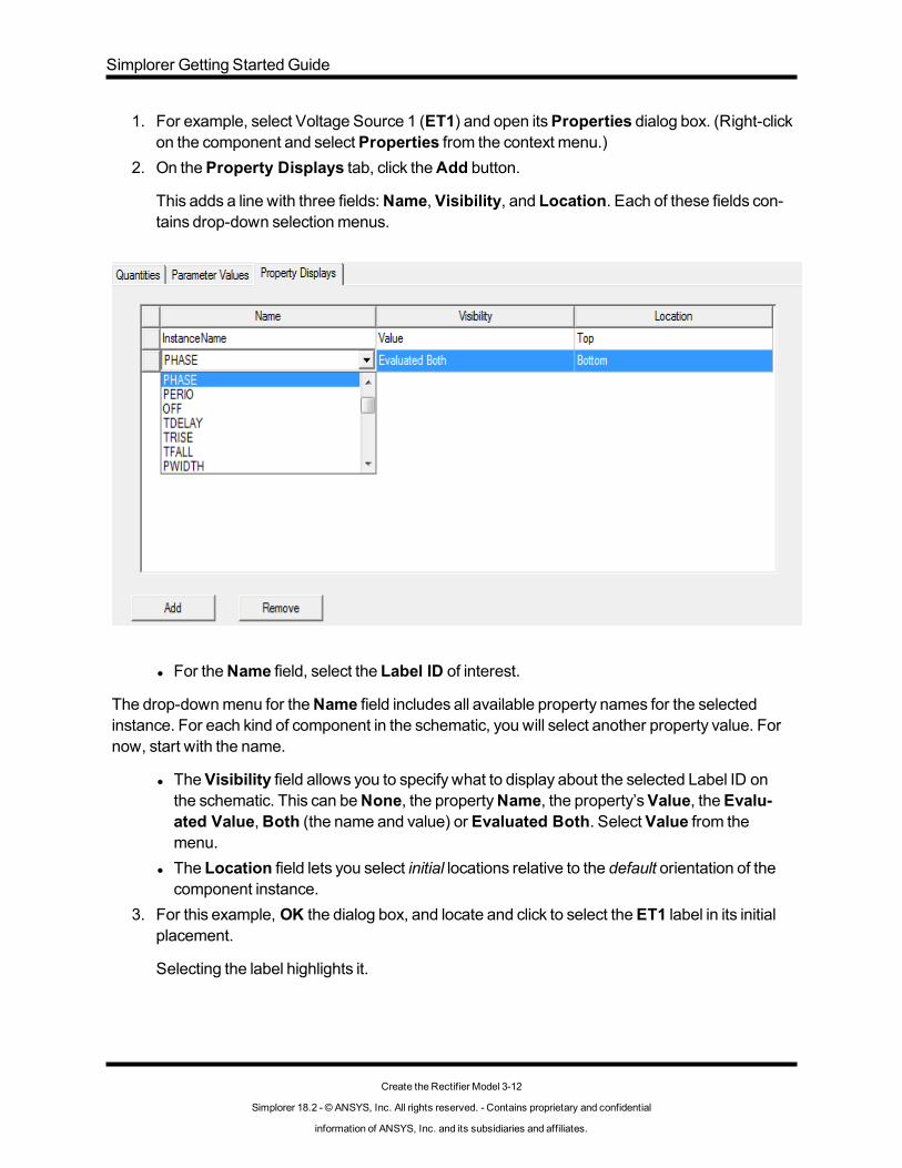
1. For example, select Voltage Source 1 (ET1) and open itsProperties dialog box. (Right-clickon the component and selectProperties from the context menu.)
2. On theProperty Displays tab, click theAdd button.
This adds a line with three fields:Name, Visibility, and Location. Each of these fields con-tains drop-down selectionmenus.
l For theName field, select the Label ID of interest.
The drop-downmenu for theName field includes all available property names for the selectedinstance. For each kind of component in the schematic, you will select another property value. Fornow, start with the name.
l TheVisibility field allows you to specify what to display about the selected Label ID onthe schematic. This can beNone, the propertyName, the property’sValue, theEvalu-ated Value,Both (the name and value) or Evaluated Both. SelectValue from themenu.
l The Location field lets you select initial locations relative to the default orientation of thecomponent instance.
3. For this example, OK the dialog box, and locate and click to select theET1 label in its initialplacement.
Selecting the label highlights it.
Create the Rectifier Model 3-12
Simplorer 18.2 - © ANSYS, Inc. All rights reserved. - Contains proprietary and confidential
information of ANSYS, Inc. and its subsidiaries and affiliates.

Simplorer Getting Started Guide
4. Drag the label to a position above the component instance.5. With the label highlighted, you can click theRotate icon on the toolbar, or useDraw>Rotate
to rotate the label as needed.6. Open theProperties dialog again, and select theProperty Displays tab again.
Note that the Location field for theName property now showsCustom.
7. Now click theAdd button again.8. This time, use the drop-downmenu in theName field to locate and selectPHASE.9. For Visibility, selectEvaluated Both andOK the dialog.
The labelPHASE=0 should now be visible on the schematic.
10. Drag thePHASE=0 label to a position to the left of the component as shown in the figure.11. Use the foregoing techniques to activate labels for the rest of the components tomatch the
schematic figure.
Create the Rectifier Model 3-13
Simplorer 18.2 - © ANSYS, Inc. All rights reserved. - Contains proprietary and confidential
information of ANSYS, Inc. and its subsidiaries and affiliates.

Simplorer Getting Started Guide
l For the Resistors, add “Name” and “R” name.l For the Inductors, add “Name” and the “L” name.l For the Diodes, add only “Name” to the display.l For the Capacitor, add “Name” and “C”.
12. Save your work before continuing to the next step.
Note You can also set the visibility and initial location for properties you wish to display by double-clicking on a component to open its Parameters dialog box. TheOutput/Display tab hasdrop-downmenus for setting theVisibility and Location for each property.
Create the Rectifier Model 3-14
Simplorer 18.2 - © ANSYS, Inc. All rights reserved. - Contains proprietary and confidential
information of ANSYS, Inc. and its subsidiaries and affiliates.

Simplorer Getting Started Guide
Specifying Simulation Outputs
During a simulationmany types of data are generated based on outputs that you specify. Thesecan include quantities such as voltage, current, frequency, phase angle, torque, and displacement.
Using the outputs you define, you can also create reports of simulation results, or plot output quant-ities specified by probes that you place in the schematic.
To define simulation outputs for the examplemodel:
1. ClickSimplorer Circuit>Output Dialog. This displays theOutput dialog. TheAdd/Re-move list shows all of the schematic elements. Checkboxes control which quantities are vis-ible in the selection window.
2. TypeET in the Find field.
Thismoves the displayed list to theET elements, and opens a list of check boxes that showthe kinds of outputs you can select.
3. For ET1, check theV box.
ET1.V is now listed as aDefined Output.
Similarly, check theV boxes for ET2 andET3 to addET2.V andET3.V to theDefined Out-put list.
Create the Rectifier Model 3-15
Simplorer 18.2 - © ANSYS, Inc. All rights reserved. - Contains proprietary and confidential
information of ANSYS, Inc. and its subsidiaries and affiliates.

Simplorer Getting Started Guide
4. Use the Find field to locate theR_LOAD item and check the I box.5. Use the Find field to locate theCD element, and check theV box.
When you have finished, theDefined Output field will list the items you selected.
6. ClickOK to close the dialog box.
Next, you will define the Solution Options and Analysis Parameters to be used when analyzing thecircuit.
Create the Rectifier Model 3-16
Simplorer 18.2 - © ANSYS, Inc. All rights reserved. - Contains proprietary and confidential
information of ANSYS, Inc. and its subsidiaries and affiliates.

Simplorer Getting Started Guide
Defining Solution Options and Analysis Parameters
Simulation parameters control the simulation process. The choice of simulation parameters isimportant for a successful simulation. There are general and circuit simulator parameters. The val-ues obtained during a simulation provide valuable information about the quality of a simulation res-ult.
To set up solution options:
1. Right-click onAnalysis in theProject Manager window, and selectAdd SolutionOptions from the short-cut menu.
This displays theSolution Options dialog box.
2. On the TR tab, change the Integration formula toEuler, theMaximum number of iter-ations from 40 to 20 and the Local truncation error from 1 to 0.1. Change theName toThreePhaseOptions. Leave all other settings unchanged.
3. ClickOK to apply the changes.
An icon for the new options named ThreePhaseOptions appears underAnalysis in theProject Manager window.
4. Right-click onAnalysis in the Project Manager window, and selectSolution Setup>AddTransient from the shortcut menu.
This opens a Transient Analysis Setup dialog box.
Create the Rectifier Model 3-17
Simplorer 18.2 - © ANSYS, Inc. All rights reserved. - Contains proprietary and confidential
information of ANSYS, Inc. and its subsidiaries and affiliates.

Simplorer Getting Started Guide
5. Change simulationEnd Time from 40ms to 0.1s;Min Time Step from 10us to 1us, andMax Time Step from 1ms to 0.5ms.
6. Click theAnalysis Options button and select ThreePhaseOptions from theSelect Solu-tion Options dialog box.
7. ClickOK to close theSelect Solution Options dialog box. ClickOK again to close the Tran-sient Analysis Setup dialog box.
Now that you have set up the necessary conditions for finding solutions for the example circuit, thenext step is to start an analysis.
Starting an Analysis
To start an analysis:
1. Start the analysis (simulation) by selecting theSimplorer Circuit>Analyzemenu com-mand.
You can also right-click onAnalysis in theProject Manager window and clickAnalyze onthe short-cut menu, click theAnalyze icon on theSimplorer Simulation toolbar, or pressF12 on your keyboard to start the analysis.
Create the Rectifier Model 3-18
Simplorer 18.2 - © ANSYS, Inc. All rights reserved. - Contains proprietary and confidential
information of ANSYS, Inc. and its subsidiaries and affiliates.

Simplorer Getting Started Guide
The simulationmodel is compiled and outputs are calculated. During the simulation run, thename of themodel is visible in the simulation toolbar in theProgresswindow, and a buttonto stop the simulation is available.
2. After the simulation, the output quantities are displayed in the plots on the sheet or in thereport windows. Output data are also saved in an .sdb file (Simplorer Database).
Plotting Rectifier Model Simulation Results
In this section, you will create reports that graph the following outputs:
l Voltages of the sources ET1.V, ET2.V, and ET3.Vl Voltage of the smoothing capacitor CD.Vl Current of the load resistor R_LOAD.I
The resulting plots should resemble those shown below.
Create the Rectifier Model 3-19
Simplorer 18.2 - © ANSYS, Inc. All rights reserved. - Contains proprietary and confidential
information of ANSYS, Inc. and its subsidiaries and affiliates.

Simplorer Getting Started Guide
Begin by creating a 2D rectangular report that plots the three-phase voltage source outputs.
1. Right-click onResults in the Project tree and selectCreate Standard Report>Rect-angular Plot from the context menu.
A new Reportwindow appears.
Create the Rectifier Model 3-20
Simplorer 18.2 - © ANSYS, Inc. All rights reserved. - Contains proprietary and confidential
information of ANSYS, Inc. and its subsidiaries and affiliates.

Simplorer Getting Started Guide
2. Under Category, selectVoltage. While pressing theCtrl key, select ET1.V, ET2.V, andET3.V in theQuantity list. Keep all other settings unchanged.
Create the Rectifier Model 3-21
Simplorer 18.2 - © ANSYS, Inc. All rights reserved. - Contains proprietary and confidential
information of ANSYS, Inc. and its subsidiaries and affiliates.

Simplorer Getting Started Guide
3. Click theNew Report button to create a report similar to the following:
A Result namedXY Plot 1 appears in theProject Manager tree.
4. Without closing theNew Report dialog, select CD.V in the Quantity list.5. ClickNew Report to create a report showing the smoothing capacitor voltage similar to the
Create the Rectifier Model 3-22
Simplorer 18.2 - © ANSYS, Inc. All rights reserved. - Contains proprietary and confidential
information of ANSYS, Inc. and its subsidiaries and affiliates.

Simplorer Getting Started Guide
following:
A Result namedXY Plot 2 appears in theProject Manager tree.
6. Without closing theNew Report dialog, select Current in the Category list; then select R_LOAD.I in the Quantity list.
7. ClickNew Report to create a report showing the load resistor current similar to the fol-
Create the Rectifier Model 3-23
Simplorer 18.2 - © ANSYS, Inc. All rights reserved. - Contains proprietary and confidential
information of ANSYS, Inc. and its subsidiaries and affiliates.

Simplorer Getting Started Guide
lowing:
A Result namedXY Plot 3 appears in theProject Manager tree.
8. ClickClose to close theNew Report dialog box.
Simplorer allows you to customize reports such as the one you created in this example in manyways. For example, you can rename plots by right-clicking on a plot name in theProject Managertree, and selectingRename from the context menu. You can also adjust the background color; gridscale and color; text font, size, and color; trace color, line style, and thickness; legend text; add vari-ous datamarkers, etc.
You can also use the tools in Simplorer’sDrawmenu to add your own custom elements and text toyour reports. Detailed information onGenerating andModifying Reports is available in the onlinehelp.
Create the Rectifier Model 3-24
Simplorer 18.2 - © ANSYS, Inc. All rights reserved. - Contains proprietary and confidential
information of ANSYS, Inc. and its subsidiaries and affiliates.

4 - Hysteresis Current-Controlled DC-MotorStart-Up
In this chapter, the example from chapter 3 ismodified as follows:
l The resistive/inductive load is replaced with a real machinemodel (DC motor with per-manent excitation).
l The example is then expanded to create a simple, current-controlledmachinemodel byadding a two-point hysteresis element, a chopper transistor, and a freewheeling diode.The other parts of the circuit — the three-phase power supply with rectifier bridge— remainunchanged.
l In the second example, the controller ismodeled with state graph components.
Modify the Rectifier Model DesignThe figure below shows a Schematic sheet of the simulationmodel you will design in this section.Themodel consists of a three phase power supply, a rectifier bridge with static diodes and theircharacteristics, a smoothing capacitor, a DC machinemodel, Chopper transistor, and freewheelingdiode.
Simplorer Getting Started Guide
Hysteresis Current-Controlled DC-Motor Start-Up 4-1
Simplorer 18.2 - © ANSYS, Inc. All rights reserved. - Contains proprietary and confidential
information of ANSYS, Inc. and its subsidiaries and affiliates.

Simplorer Getting Started Guide
Deleting the Resistive/Inductive Load
First, you need to delete the components which are not used in themodified simulationmodel. Inplace of the resistive/inductive load, you will add a DC machinemodel, a freewheeling diode, and achopper transistor.
1. Select and delete resistorR_LOAD and inductor L_LOAD.
You can select them one at a time (selected elements turn red); or drag themouse aroundthem to select both elements.
To delete the selected components you can:
l ChooseEdit>Delete.l Right-click and chooseDelete from the short-cut menu.l PressCTRL+X.
2. Select and delete the remains of the interconnecting wires.
Saving the Sheet with a New Name1. Choose File>Save As.2. Enter a new file name.3. ClickOK.
Placing and Arranging the New Block Components on the Sheet
First, place and arrange the new components needed for the PI Controller in the extended sim-ulationmodel. TheComponent Libraries provides access to the library containing the Simplorerbasic components, which are used for this example.
Hysteresis Current-Controlled DC-Motor Start-Up 4-2
Simplorer 18.2 - © ANSYS, Inc. All rights reserved. - Contains proprietary and confidential
information of ANSYS, Inc. and its subsidiaries and affiliates.

Simplorer Getting Started Guide
Module Group Component QuantityBlocks Continuous Blocks GAIN: Gain
INTG: Integrator
2
1
Sources Blocks CONST: Constant Value 1
Signal Processing Blocks LIMIT: Limiter
SUM: Summation
1
3
Tools Time Functions DATAPAIRS: 2D Look-up Table 1
1. Open the SimplorerBasic Elementsmodel library folder by clicking the + symbol next to thefolder. You can also double-click theBasic Elements folder icon or name to open it.
2. Place the component onto the sheet. Select the folder Blocks and then the folderContinuous Blocks. Select the componentGain and drag the component onto the sheet.
3. Arrange the component on the sheet. To connect the components, youmust placethem in appropriate positions. See the simulationmodel figure on "Current and Speed Con-trolled DC Motor" on page 5-1. Orient each component as needed so that it can be easily con-nected with the other components.
4. Repeat steps 2 and 3 until all new components used in this example are placed on the sheet.
Connecting the New Components
When all the components are arranged, you can connect them as required for this example.
Connect the components as required for the controller.Using the simulationmodel shownon "Current and Speed Controlled DC Motor" on page 5-1 as a guide, place the cursor on the ele-ment pins and set the beginning, the corners, and the end of a wire with themouse. PressEsc toexit the wiremode.
Note Connections to themotor’sLOAD (load torque), IA (armature current), andN (rotorspeed) parameters are not visible on the schematic. These connectionswill be added later.
Defining DC Machine Values1. Define component properties. Double-click the DCMPmachine symbol to open itsPara-
meters dialog box.2. On theParameters tab, change theName fromDCMP… toDCM., and define the following
machine parameters:l RA: Armature Resistance:1.2 ohml LA: Armature Inductance:9.5mH
Hysteresis Current-Controlled DC-Motor Start-Up 4-3
Simplorer 18.2 - © ANSYS, Inc. All rights reserved. - Contains proprietary and confidential
information of ANSYS, Inc. and its subsidiaries and affiliates.

Simplorer Getting Started Guide
l KE: Back EMF Constant: 0.544Wbl J: Rotor Moment of Inertia:0.004 kgm2
3. In theDefault Outputs section of theParameters tab, checkN and IA to enable them asoutputs. You will use these later when creating reports.
4. Make the names of themechanical load and armature current properties visible on thesheet. (These two properties will be used later.)a. Click the Output/Display tab. In theName column, select LOAD (Load Torque). Under
Visibility, selectName. Leave Location as-is.b. Similarly set visibility and location for IA (Armature Current).c. ClickOK to apply the changes.
5. Move the property names to appropriate positions.
You can rotate property names displayed on the sheet by clicking the name to highlight it,then pressingCtrl+R repeatedly until the name is oriented as desired. Activate themovemode bymoving themouse pointer over the name you want to move until themouse-pointerchanges into a pointer with a four-headed arrow. Click and drag the name to the new pos-ition.
Defining Mechanical Load
Themechanical load of themachinemodel can be set in many different ways. The variant used inthis example is based on an initial value (ICA) component. This component is useful when initial val-ues are used for different models on the sheet. In this example, the equation defined within the ICAcomponent is used to “connect” an initial value, 0, to the load torque parameter of themachine com-ponent. Values in the ICA component are set only once at the simulation start.
1. Define a new entry within the initial value list.a. Double-click the ICA symbol to open itsParameters dialog box.b. On theState tab, change theName to FML_INIT and checkShow Name.c. Create a new Equation entry with theAdd (yellow lightning-bolt) button.d. Click in theEquation field and type LOAD:=0. This creates a new ICA parameter
named LOAD and assigns it a value of 0 (zero).
Hysteresis Current-Controlled DC-Motor Start-Up 4-4
Simplorer 18.2 - © ANSYS, Inc. All rights reserved. - Contains proprietary and confidential
information of ANSYS, Inc. and its subsidiaries and affiliates.

Simplorer Getting Started Guide
e. To display the LOAD parameter name and value, check the LOAD parameter’sShowcheck box.
f. ClickOK to apply the changes. The new parameter is now defined and is available forconnecting with a quantity.
2. Connect the ICA initial value to the LOAD property of the DC machine.a. Double-click the DC machine symbol to open itsParameters dialog box.b. On the Parameters tab, type LOAD in the Value cell for the LOAD property, and click
OK. This “connects” the DC machine LOAD property to the LOAD value specified in theICA component.
Freewheeling DiodeDefine the parameters of the diode.
1. Double-click the diode symbol to open itsParameters dialog box and set parameters.2. Change theName fromDn toD7.3. Select Type and chooseExponential Function from the list.4. Leave all other values as they are. ClickOK to apply the changes.
Chopper TransistorThe transistor turns on and off depending on themachine current, IA. Initially, the transistor is set“on” to start the process.
Define the parameters of the transistor.
Hysteresis Current-Controlled DC-Motor Start-Up 4-5
Simplorer 18.2 - © ANSYS, Inc. All rights reserved. - Contains proprietary and confidential
information of ANSYS, Inc. and its subsidiaries and affiliates.

Simplorer Getting Started Guide
1. Double-click the transistor symbol to open itsParameters dialog box.2. Change theName fromBJTn to TR1.3. Select Type and chooseExponential Function from the list.4. Leave all other values as they are. ClickOK to apply the changes.
Hysteresis Current-Controlled DC-Motor Start-Up 4-6
Simplorer 18.2 - © ANSYS, Inc. All rights reserved. - Contains proprietary and confidential
information of ANSYS, Inc. and its subsidiaries and affiliates.

Simplorer Getting Started Guide
Controller Modeling Using Block Elements
Initially, the current-controller is designed using a two-point element with hysteresis. The block ele-ment input signal is the DC machine current, IA. The output signal controls the chopper transistor,TR1.
1. Define component properties of the Two-point element.Double-click the symbol toopen itsParameters dialog box. On theParameters tab, change theName from TPHn toCONTR_OUT, then define the following parameters:l THRES1 (Threshold T1): 17.5l THRES2 (Threshold T2):22.5l VAL1 (Value A1):1l VAL2 (Value A2):0l Y0 (Initial Value):1
2. Define the Block sample time, TS. The smaller the block sample time, themore precisethe current control of themachine. In this example, the system sample time is used, i.e., theblock is calculated using the same sample time that the circuit models use. To ensure thatthe system sample time is used, set the TS (Sample Time) parameter to 0 (zero).
3. “Connect” the IA parameter of the DC machine (DCM) to the input of the hys-teresis block.a. First, on theOutput/Display tab, uncheckShow Pin for the INPUT parameter. For Vis-
ibility, selectBoth to display the parameter and its value.b. Next, on theParameters tab, typeDCM.IA in the INPUT parameter Value field.c. ClickOK to apply the changes. Position the text as needed.
4. Connect the output pin of the block with the input pin of the control signal of thebipolar junction transistor. The cursor changes to crosswires. Connect both pins by click-ing them. PressESC to finish the wiremode.
All parameters of themodified simulationmodel should now have the correct values. The tablebelow lists all new components of the simulationmodel and their parameter values.
Name Type ParametersDCM RA (Armature Resistance)=1.2 ohm
LA (Armature Inductance)=9.5 mH
KE (Back EMF Constant)=0.544 Wb
J (Rotor Moment of Inertia)=0.004 kgm2FML_INIT1 LOAD:=0
D7 Exponential Function ISAT (Saturation Current)=1e-012 A
VT (Thermal Voltage)=0.035 V
Hysteresis Current-Controlled DC-Motor Start-Up 4-7
Simplorer 18.2 - © ANSYS, Inc. All rights reserved. - Contains proprietary and confidential
information of ANSYS, Inc. and its subsidiaries and affiliates.

Simplorer Getting Started Guide
Name Type ParametersRR (Reverse Resistance)=100k ohm
TR1 Exponential Function ISAT (Saturation Current)=1e-012 A
VT (Thermal Voltage)=0.035 V
RR (Reverse Resistance)=100k ohm
CTRL (Control Signal)=CONTR_OUT.VAL (pin)CONTR_OUT THRES1 (Threshold T1)=17.5
THRES2 (Threshold T2)= 22.5
VAL1 (Value A1)=1
VAL2 (Value A2)=0
Y0 (Initial Value)=1
TS (Sample Time)=0 (System time)
INPUT (Input Signal)=DCM.IA
Hysteresis Current-Controlled DC-Motor Start-Up 4-8
Simplorer 18.2 - © ANSYS, Inc. All rights reserved. - Contains proprietary and confidential
information of ANSYS, Inc. and its subsidiaries and affiliates.

Simplorer Getting Started Guide
Modifying Report Elements
1. Define the model output DCM.N.a. In the Project Manager window, under Results on the Project tab, double-click theXY
Plot 1 report icon to open the report window.b. Ctrl+click each of the traces to select them all, then pressDelete to remove the traces.
You can also right-click and selectEdit>Delete from the context menu.c. Right-click theXY Plot 1 report icon and selectModify Report to open the report dialog
box.d. In theCategory list, clickAll, then selectDCM.N in theQuantity list.e. Click theAdd Trace button to display the output.f. ClickClose to close the dialog box.g. In theProject Manager window, right-clickXY Plot 1 and selectRename from the con-
text menu. Change the title of the plot toSpeed. PressEnter to apply the change.2. Define the model output DCM.IA.
a. Double-click theXY Plot 2 symbol to open the report window.b. Select theCD.V trace and use theDelete button to delete it.c. Create a new output forDCM.IA.d. Change the title of the plot toCurrent. See also Plotting Rectifier Model Simulation Res-
ults.
Display Diode CharacteristicPlots can also be used to display component characteristics. For such cases, the X-axis is definedin some quantity other than simulation time.
1. Define the axes quantities.a. In the Project Manager window, under Results on the Project tab, double-click theXY
Plot 3 symbol to open the report dialog box.b. Select theR_LOAD.I trace andDelete it.c. Create a new Y-axis output forD1.I. Remember to useSimplorer Circuit>Output Dia-
log to define output quantities as needed.d. Select a new X-axis quantity by uncheckingDefault. Then click [...] and selectD1.V on
the Select X Component dialog box.
Hysteresis Current-Controlled DC-Motor Start-Up 4-9
Simplorer 18.2 - © ANSYS, Inc. All rights reserved. - Contains proprietary and confidential
information of ANSYS, Inc. and its subsidiaries and affiliates.

Simplorer Getting Started Guide
e. ClickOK to close the Select X Component dialog box.f. In the report dialog box, clickApply Trace to apply the changes; then clickClose to
close the dialog box.g. By default, the trace type is a continuous (solid) line. To edit the trace properties so that
you can see the individual simulation points on the curve, click the trace to select it (Thecursor changes color when hovering over a selectable display element). In the dock-ableProperties window, change the Trace Type toDiscrete.
To view the area of interest on the characteristic curve, you need tomanually edit the X- and Y-axisproperties.
a. Double-click the X-axis to select it and open itsProperties dialog box.b. On theScaling tab, uncheckAuto Units and selectV as theUnits value. CheckSpe-
cify Min, then enter 0.55 in theMin Value field. Similarly, checkSpecify Max and enter0.9 for theMax value. Next checkSpecify Spacing and enter 0.05 in theSpacing fieldto set the interval betweenmajor tickmarks on the X-axis. Leave the rest of the settingsas they are and clickOK to apply the changes and close the dialog box.
c. Double-click the Y-axis to select it and open itsProperties dialog box.d. On theScaling tab, uncheckAuto Units and selectA as theUnits value. CheckSpe-
cify Min and enter 0 in theMin Value field. CheckSpecify Max and enter 0.1 for theMax value. CheckSpecify Spacing and enter 0.025 in theSpacing field to set the inter-val betweenmajor tickmarks on the Y-axis. Leave the rest of the settings as they are andclickOK to apply the changes and close the dialog box.
e. Change the title of the plot toCharacteristic.
Hysteresis Current-Controlled DC-Motor Start-Up 4-10
Simplorer 18.2 - © ANSYS, Inc. All rights reserved. - Contains proprietary and confidential
information of ANSYS, Inc. and its subsidiaries and affiliates.

Simplorer Getting Started Guide
Defining Simulation ParametersSimulation parameters control the simulation process. The values chosen for a simulation determ-ine the success, and affect the quality, of a simulation result.
1. ChooseSimplorer Circuit>Add Solution Setup>Transient to define the simulation para-meters.
2. Change the default values for simulationEnd Time from 40ms to 0.5ms, forMin Time Stepfrom 10us to 1ns, and forMax Time Step from 1ms to 1us. ClickOK to apply the changes.
Starting Simulation (Block Components)Start the simulation with theSimplorer Circuit>Analyzemenu command or right-click on theAnalysis icon in theProject Manager window and selectAnalyze from the short-cut menu. Thesimulationmodel is compiled and calculated.
Simulation Results (Block Components)
The Speed and Current plots display the simulation results for themachine armature current(DCM.IA) and speed (DCM.N). Depending on the armature current, the two-point element withhysteresis controls the switching behavior of the chopper transistor. The speed for the DC motorno-load starting torque approaches 2613 rpm.
The Characteristic plot displays diode D1’s current as a function of its voltage and should look sim-ilar to the image below.
Hysteresis Current-Controlled DC-Motor Start-Up 4-11
Simplorer 18.2 - © ANSYS, Inc. All rights reserved. - Contains proprietary and confidential
information of ANSYS, Inc. and its subsidiaries and affiliates.

Simplorer Getting Started Guide
Controller Modeling Using State Graph ComponentsSimplorer’s state graphmodule, which is based on thePetri Net theory, allows you tomodel event-driven, discontinuous processes. The theoretical basis of themodeling divides a system into sig-nificant states and events, and transitions from one state to the other. The following procedureexplains themodeling of the two-point hysteresis controller with state graph components.
First, place and arrange the state graph components used in themodified simulationmodel. Anyunused area of the sheet may be used.
1. Choose the Simplorer model library Basic Elements.2. Place the component onto the sheet. Select the folder States.Select the componentState
11and drag it onto the sheet.3. Arrange the component on the sheet. Orient the component so that it can be connected with
the other components in themanner show in figure below.4. Repeat steps 2 and 3 until all new components used in the state graph are placed on the
sheet
Module Group ComponentStates State 11 2x
Transition 2x
Tools Equations Initial Values 1x
Hysteresis Current-Controlled DC-Motor Start-Up 4-12
Simplorer 18.2 - © ANSYS, Inc. All rights reserved. - Contains proprietary and confidential
information of ANSYS, Inc. and its subsidiaries and affiliates.

Simplorer Getting Started Guide
5. All of the required components for the state graph are now on the sheet. To connect the com-ponents, youmust place them in appropriate positions as shown in the figure below. Note inparticular the directions of the arrows on the Transition components and rotate or flip com-ponents as needed.
Connecting the State Graph Components
When all of the state graph components are arranged, you can connect them as required for thisexample. Make certain to consider the direction of the transition components.
1. Activate the wire mode.ChooseDraw>Wire or use theCtrl+W keyboard shortcut. Thecursor changes to crosswires.
2. Connect the components as required for the circuit.Place the cursor on the elementpins and set the beginning, the corners, and the end of a wire with themouse. PressEsc tofinish and exit the wiremode.
Defining the Properties of State Graph Components
A process sequence can be considered as a sequence of states. The current state is called active.Switching the activity from a given state to its successor state is called an event. An event occursonly if: all previous states are active, all following states are inactive, and the transfer condition— inthe form of a logical expression— is true. At the beginning of the simulation, one statemust bedefined as active.
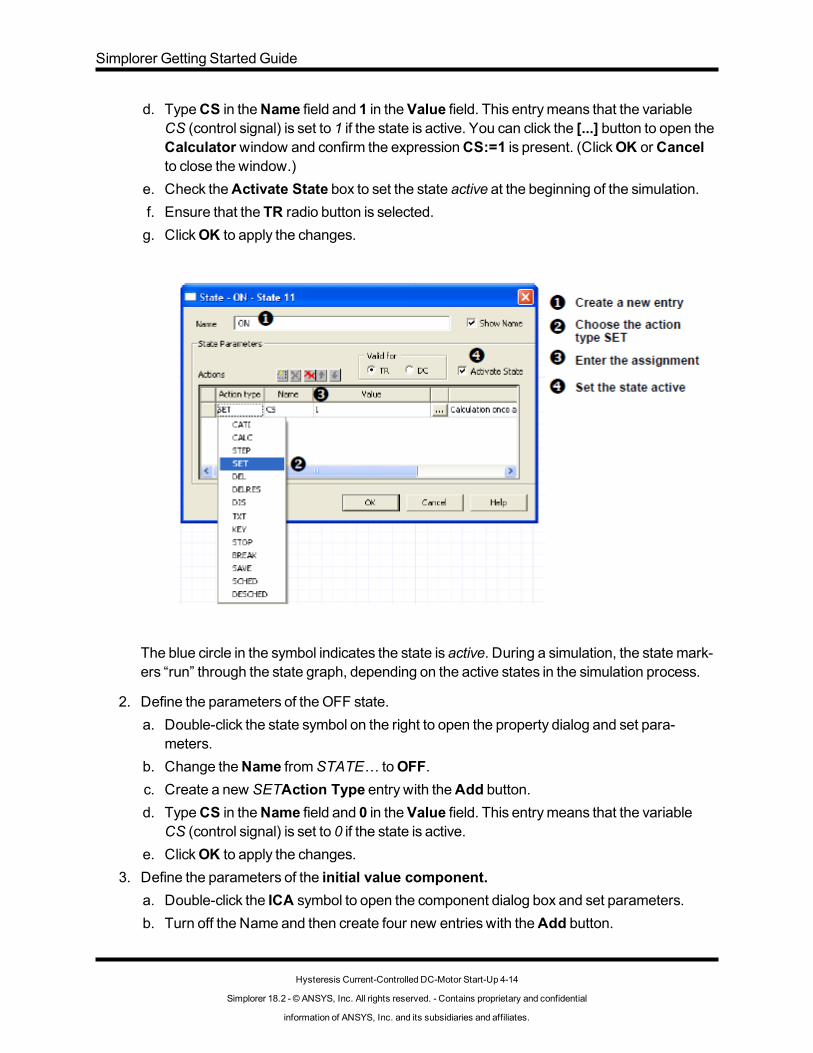
1. Define the parameters of the state ON.a. Double-click theSTATE11 symbol on the left to open its Parameters dialog box.b. Change theName fromSTATE… toON.c. Create a new SETAction Type entry with theAdd button.
Hysteresis Current-Controlled DC-Motor Start-Up 4-13
Simplorer 18.2 - © ANSYS, Inc. All rights reserved. - Contains proprietary and confidential
information of ANSYS, Inc. and its subsidiaries and affiliates.
Simplorer Getting Started Guide
d. TypeCS in theName field and 1 in theValue field. This entrymeans that the variableCS (control signal) is set to 1 if the state is active. You can click the [...] button to open theCalculator window and confirm the expressionCS:=1 is present. (ClickOK orCancelto close the window.)
e. Check theActivate State box to set the state active at the beginning of the simulation.f. Ensure that the TR radio button is selected.g. ClickOK to apply the changes.
The blue circle in the symbol indicates the state is active. During a simulation, the statemark-ers “run” through the state graph, depending on the active states in the simulation process.
2. Define the parameters of the OFF state.a. Double-click the state symbol on the right to open the property dialog and set para-
meters.b. Change theName fromSTATE… toOFF.c. Create a new SETAction Type entry with theAdd button.d. TypeCS in theName field and 0 in theValue field. This entrymeans that the variable
CS (control signal) is set to 0 if the state is active.e. ClickOK to apply the changes.
3. Define the parameters of the initial value component.a. Double-click the ICA symbol to open the component dialog box and set parameters.b. Turn off the Name and then create four new entries with theAdd button.
Hysteresis Current-Controlled DC-Motor Start-Up 4-14
Simplorer 18.2 - © ANSYS, Inc. All rights reserved. - Contains proprietary and confidential
information of ANSYS, Inc. and its subsidiaries and affiliates.

Simplorer Getting Started Guide
c. Click in theEquation field and type the name:=value corresponding to the picture.
You can also enter a description of each equation in the Information field and display the descrip-tions on the schematic by enablingShow.
d. ClickOK to apply the changes.4. Define the parameters of the first transition.
a. Double-click the top Transition symbol to open the parameter dialog box.b. TypeDCM.IA>=IUPR in theCondition for transition field. This entrymeans that the
condition becomes true if themachine armature current (DCM.IA) is greater-than orequal-to the variable IUPR. The variable IUPR is defined in the initial value component.
c. Clear Show Name.d. CheckShow Condition to display the condition on the schematic.e. ClickOK to apply the changes.
5. Define the parameters of the second transition.a. Double-click the lower Transition symbol to open the parameter dialog box to define the
transfer condition.b. TypeDCM.IA<=ILWR in theCondition for transition field. This entrymeans that the
condition becomes true if themachine armature current is less-than or equal-to the vari-able ILWR. This variable is also defined in the initial value component.
c. Turn off the name, and checkShow Condition to display the parameter value.d. ClickOK to apply the changes.
Note Using the “=” operator type forces the simulator to synchronize on the conditionwith theminimum time step. Because of this, the state graph worksmore pre-cisely than the two-point hysteresis component, but the processing time of thesimulation is longer.
Hysteresis Current-Controlled DC-Motor Start-Up 4-15
Simplorer 18.2 - © ANSYS, Inc. All rights reserved. - Contains proprietary and confidential
information of ANSYS, Inc. and its subsidiaries and affiliates.

Simplorer Getting Started Guide
Using Name References
To control the switching behavior of the transistor, TR1, you need to enter the control variableCSin the transistor dialog.
1. Double-click the transistor symbol to open the Parameters dialog to define the control para-meter.
2. Clear theControl SignalUse Pin box, and enter the control variableCS in theControl Sig-nal field.
3. ClickOK to apply the changes.
Deactivating Components on the Sheet
You can deactivate separate components or parts of amodel sheet for a simulation run. The com-ponents and all of their properties remain on the sheet, but the simulator ignores the deactivatedcomponents. The connection between the terminals is considered open. This feature is especiallyhelpful when you want to test simulationmodels with several different elements and parameters.Components can be deactivated with theEdit>Deactivate (Open)menu command or the samecommand in the shortcut menu for the selected element. A deactivated (Open) component willhave a large redX over it.
Select the hysteresis blockCONTR_OUT and chooseEdit>Deactivate (Open). The wires, con-nected with themachinemodel and transistor, remain on the sheet.
Hysteresis Current-Controlled DC-Motor Start-Up 4-16
Simplorer 18.2 - © ANSYS, Inc. All rights reserved. - Contains proprietary and confidential
information of ANSYS, Inc. and its subsidiaries and affiliates.

Simplorer Getting Started Guide
All parameters in themodified simulationmodel now have the correct values. The table below listsall new components of the simulationmodel and their parameter values.
Name Type ParametersTR1 Exponential Function Saturation Current [A]=1e-12
Thermal Voltage[V]=0.035
Reverse Resistance[Ω]=100k
Control Signal=CSCONTR_OUT Deactivated Threshold T1=17.5
Threshold T2= 22.5
Value A1=1
Value A2=0
Initial Value=1
Sample Time=0 (System)
Input=DCM.IATRANS1 DCM.IA>=IUPRTRANS2 DCM.IA<=ILWRON SET:CS:=1OFF SET:CS:=0FML_INIT2 IREF:=20
Hysteresis Current-Controlled DC-Motor Start-Up 4-17
Simplorer 18.2 - © ANSYS, Inc. All rights reserved. - Contains proprietary and confidential
information of ANSYS, Inc. and its subsidiaries and affiliates.

Simplorer Getting Started Guide
Name Type ParametersDELTA:=2.5
IUPR:=IREF+DELTA
ILWR:=IREF-DELTA
Starting Simulation (State Graph)
Start the simulation with theSimplorer Circuit>Analyzemenu command or the right click on theAnalysis icon on the Project window and selectAnalyze from the short-cut men. The simulationmodel is compiled and calculated.
Simulation Results (State Graph)
TheSpeed andCurrent plots display the simulation results for themachine armature current(DCM.IA) and speed (DCM.N). Depending on the armature current,DCM.IA, the state graph con-trols the switching behavior of the chopper transistor. The speed for the DC motor no-load startingcondition approaches 2550 rpm.
The tolerance band of the state graph controller ismore precise than for the hysteresis controller,because the “=” operator type in the state graph forces the simulator to synchronize on the con-dition with theminimum time step. To force any of the blockmodels to calculatemore precisely, youcan define a special sample time in themodel’s property dialog.
Hysteresis Current-Controlled DC-Motor Start-Up 4-18
Simplorer 18.2 - © ANSYS, Inc. All rights reserved. - Contains proprietary and confidential
information of ANSYS, Inc. and its subsidiaries and affiliates.

5 - Current and Speed Controlled DC MotorIn this chapter the example fromChapters 3 and 4 is extended further:
l The state graph/hysteresis controller is replaced with a PI (proportional-integral) controllerimplemented using block components.The other parts of the circuit, such as the three-phase power supply with rectifier bridge,remain unchanged.
In addition to basic functions (selecting, placing, arranging, and connecting components), thischapter introduces the following Simplorer features:
l Modeling with block componentsl Examining Block Sequencel Using Pins for parameter transferl Using Characteristic components
Modify the State Graph DesignThe figure below shows the Schematic sheet of the simulationmodel with the corresponding val-ues of components: three phase power supply, the rectifier bridge, smoothing capacitor, motor,and the PI controller.
Simplorer Getting Started Guide
Current and Speed Controlled DC Motor 5-1
Simplorer 18.2 - © ANSYS, Inc. All rights reserved. - Contains proprietary and confidential
information of ANSYS, Inc. and its subsidiaries and affiliates.

Simplorer Getting Started Guide
Deleting the State Graph
First, you need to delete the components that are not used in themodified simulationmodel.Instead of the state graph or simple hysteresis controller, you will use a PI controller consisting ofblock diagram components.
1. Select the components to delete. Hold down theCtrl key and select the state graph com-ponents: FML_INIT1, and FML_INIT2, STATE_11 (both ON andOFF), and the two Trans-ition components by clicking them to highlight the components.
2. Delete the components. ChooseEdit>Cut. The components are removed from the sheet.You can also pressCtrl and theX key at the same time; or you can use theDelete key onyour keyboard.
Current and Speed Controlled DC Motor 5-2
Simplorer 18.2 - © ANSYS, Inc. All rights reserved. - Contains proprietary and confidential
information of ANSYS, Inc. and its subsidiaries and affiliates.

Simplorer Getting Started Guide
3. Delete the remaining wires. Select any remaining unused wires by holding down theCtrlkey and clicking to select them. PressCtrl+X to remove the wires.
Saving the Sheet with a New Name1. Choose File>Save As.2. Enter a new file name.3. ClickOK.
Placing and Arranging the New Block Components on the Sheet
First, place and arrange the new components needed for the PI Controller in the extended sim-ulationmodel. TheComponent Libraries provides access to the library containing the Simplorerbasic components, which are used for this example.
Module Group Component QuantityBlocks Continuous Blocks GAIN: Gain
INTG: Integrator
2
1
Sources Blocks CONST: Constant Value 1
Signal Processing Blocks LIMIT: Limiter
SUM: Summation
1
3
Tools Time Functions DATAPAIRS: 2D Look-up Table 1
1. Open the SimplorerBasic Elementsmodel library folder by clicking the + symbol next to thefolder. You can also double-click theBasic Elements folder icon or name to open it.
2. Place the component onto the sheet. Select the folder Blocks and then the folderContinuous Blocks. Select the componentGain and drag the component onto the sheet.
3. Arrange the component on the sheet. To connect the components, youmust placethem in appropriate positions. See the simulationmodel figure on "Current and Speed Con-trolled DC Motor" on page 5-1. Orient each component as needed so that it can be easily con-nected with the other components.
4. Repeat steps 2 and 3 until all new components used in this example are placed on the sheet.
Connecting the New Components
When all the components are arranged, you can connect them as required for this example.
Connect the components as required for the controller.Using the simulationmodel shownon "Current and Speed Controlled DC Motor" on page 5-1 as a guide, place the cursor on the ele-ment pins and set the beginning, the corners, and the end of a wire with themouse. PressEsc toexit the wiremode.
Current and Speed Controlled DC Motor 5-3
Simplorer 18.2 - © ANSYS, Inc. All rights reserved. - Contains proprietary and confidential
information of ANSYS, Inc. and its subsidiaries and affiliates.

Simplorer Getting Started Guide
Note Connections to themotor’sLOAD (load torque), IA (armature current), andN (rotorspeed) parameters are not visible on the schematic. These connectionswill be added later.
Defining Mechanical Load (Block)
TheDATAPAIRS: 2D Look-up Table (already placed on the sheet) allows the definition ofwave-forms from a set of fixed data points either with linear interpolation between them (straightlines from point-to-point), or rectangular lines between them (two orthogonal lines— parallel to thecoordinate axes— from point-to-point). The X-values of the data-pairsmust bemonotonouslyincreasing. The last slope is effective for all values outside the X range. If you want to have a con-stant value outside the X-range, you need to define two data-pairs with the same Y-value at theend. In this example, the 2D Lookup Table is used to define themechanical load of the DCmachine.
1. Define the load characteristic.a. Double-click the 2D Look-up Table symbol to open theParameters dialog box and set
parameters.b. Change theName to LOAD.c. ChooseWithout from the Interpolation list.d. ClickCharacteristic to open theCharacteristic dialog box.e. Choose the Internal Reference radio button, then clickDatasets to open theDatasets
dialog box.f. ClickAdd to open anAdd Dataset dialog box. Enter the values as shown in the figure
below.g. A default unique name is assigned to each dataset. Change theName to something
more descriptive such as Load_Torque.
Current and Speed Controlled DC Motor 5-4
Simplorer 18.2 - © ANSYS, Inc. All rights reserved. - Contains proprietary and confidential
information of ANSYS, Inc. and its subsidiaries and affiliates.

Simplorer Getting Started Guide
h. ClickOK to save the dataset. TheAdd Dataset dialog box closes - returning you to themainDatasets dialog box.
i. ClickDone to close theDatasets dialog box. TheCharacteristic dialog box should nowshow the name of the dataset you created in itsDataset field.
j. ClickOK to close this dialog box.k. On the 2D Look-up TableParameters tab, checkValue in theOutputs section.l. ClickOK to close the 2D Look-up TableParameters dialog box.
2. Connect the output parameter value of the LOAD characteristic with the load ofthe DC machine.a. Open the LOAD characteristicParameters dialog box.b. On theOutput/Display tab, uncheckShow Pin for theVAL parameter, and clickOK to
close the dialog box.c. On theParameters tab of the DC machineParameters dialog box, type LOAD.VAL in
theValue field for the LOAD parameter. This connects the LOAD element characteristicoutput to themachine’s LOAD input parameter.
d. In theDefault Outputs section, ensure thatN and IA are checked to enable them to beused later when creating reports.
e. ClickOK to close the dialog box.
Current and Speed Controlled DC Motor 5-5
Simplorer 18.2 - © ANSYS, Inc. All rights reserved. - Contains proprietary and confidential
information of ANSYS, Inc. and its subsidiaries and affiliates.

Simplorer Getting Started Guide
Defining the PI ControllerThe components that have been placed and connected still have their default parameter values.You will now assign proper values for the components that comprise the PI Controller. Use the sim-ulationmodel figure "Current and Speed Controlled DC Motor" on page 5-1 as a guide.
1. Define the parameters of the first gain block.a. Double-click theGain block symbol to open itsParameters dialog box.b. On theParameters tab, change theName toN.c. Type -16.6667 for theKP (Proportional Gain) parameter Value and selectm for its
Units.d. Change the parameter Value toDCM.N*1. This “connects” the gain block input to the
DC machine’s rotor speed output parameter with a scaling factor of 1. On theOut-put/Display tab, uncheckShow Pin for the INPUT parameter.
e. ClickOK to close the dialog box.2. Define the parameters of the constant value block.
a. Double-click theCONST block symbol to open itsParameters dialog box.b. Change theName toN_REF and theValue to 16.6667. Ensure thatUse System
Sample Time is checked and thatBlock Output Signal is unchecked.c. ClickOK to apply the changes.
3. Define the parameters of the summation of the N gain block and the N_REF constant block.a. Double-click the summation symbol to the right of theN gain block to open itsPara-
meters dialog box.b. Ensure thatUse System Sample Time is checked and thatBlock Output Signal is
not checked.c. ClickOK to apply the changes.
4. Define the parameters of the second gain block.a. Double-click theGAIN block symbol to open itsParameters dialog box.b. Change theName toP_GAIN and the Proportional Gain (KP) to 50.c. ClickOK to apply the changes.
5. Define the parameters of the integrator block.a. Double-click the I block symbol to open itsParameters dialog box.b. Change theName to I_GAIN and the Integral Gain (KI) to 20. The specification of “0” for
upper limit (UL) and lower limit (LL) means that there is no limitation.c. ClickOK to apply the changes.
6. Define the parameters of the summation of P_GAIN and I_GAIN.a. Double-click the summation symbol to the right of theP_GAIN block to open itsPara-
meters dialog box.
Current and Speed Controlled DC Motor 5-6
Simplorer 18.2 - © ANSYS, Inc. All rights reserved. - Contains proprietary and confidential
information of ANSYS, Inc. and its subsidiaries and affiliates.

Simplorer Getting Started Guide
b. Ensure thatUse System Sample Time is checked and thatBlock Output Signal isnot checked.
c. ClickOK to apply the changes.7. Define the parameters of thelimiter block.
a. Double-click the limiter symbol to open itsParameters dialog box.b. Change theName to LIMITER and the Upper Limit of Output Signal (UL) to 20.c. ClickOK to apply the changes.
8. Define the parameters of thesummation of machine current and limiter value.a. Double-click the summation symbol to the right of the LIMITER block to open itsPara-
meters dialog box.b. For INPUT[1], un-checkUse Pin.c. EnterDCM.IA in the Input Signal field to link the DC machine armature current to
INPUT[1].d. Click in theSign column and select “–” from the list. The sign is applied to theDCM.IA
input signal.e. Ensure thatUse System Sample Time is checked and thatBlock Output Signal is
not checked.f. ClickOK to apply the changes.
9. Modify the parameters of thehysteresis block.a. Right-click the hysteresis block symbol and choose Activate on the context menu.b. Double-click the hysteresis block symbol to open itsParameters dialog box.c. Define the parameters as follows:
l THRES1 (Threshold T1):-2.5l THRES2 (Threshold T2):2.5l VAL1 (Value A1):0l VAL2 (Value A2): 1l Y0 (Initial Value):1l TS (Sample Time):5with unitsus
Current and Speed Controlled DC Motor 5-7
Simplorer 18.2 - © ANSYS, Inc. All rights reserved. - Contains proprietary and confidential
information of ANSYS, Inc. and its subsidiaries and affiliates.

Simplorer Getting Started Guide
d. ClickOK to apply the changes.10. Modify the parameters of transistor TR1.
a. Right-click the TR1 symbol to open itsParameters dialog box.b. On theParameters tab, clear theControl Signal field, then checkUse Pin to recon-
nect the transistor's control pin to the output of the hysteresis block.c. ClickOK to close the dialog box.
All parameters of the PI controller should now have the correct values. The table below lists all com-ponents of the PI controller and their parameter values.
Name Output To ParametersN SUM1 KP (Proportional Gain)=-16.6667m
TS (Sample Time)=System (0)
INPUT (Input Signal)=DCM.NN_REF SUM1 Value=16.6667
Sample Time=System
SUM1 P_GAIN
I_GAIN
Sample Time=System
Input[0]=N.VAL
INPUT[1]=N_REF.VALP_GAIN SUM2 KP (Proportional Gain)=50
TS (Sample Time)=System (0)
INPUT (Input Signal)=SUM1.VALI_GAIN SUM2 KI (Integral Gain)=20
Y0 (Initial Value)=0
UL (Upper Limit)=0
LL (Lower Limit)=0
TS (Sample Time)=System (0)
INPUT (Input Signal)=SUM1.VALSUM2 LIMITER Sample Time=System
Input[0]=P_GAIN.VAL
INPUT[1]=I_GAIN.VALLIMITER SUM3 UL (Upper Limit)=20
LL (Lower Limit)=0
Current and Speed Controlled DC Motor 5-8
Simplorer 18.2 - © ANSYS, Inc. All rights reserved. - Contains proprietary and confidential
information of ANSYS, Inc. and its subsidiaries and affiliates.

Simplorer Getting Started Guide
Name Output To ParametersTS (Sample Time)=System (0)
INPUT (Input Signal)=SUM2.VALSUM3 CONTR_OUT Sample Time=System
Input[0]=LIMITER.VAL
INPUT[1]=-DCM.IACONTR_OUT TR1.CTRL THRES1 (Threshold T1)=-2.5
THRES2 (Threshold T2)= 2.5
VAL1 (Value A1)=0
VAL2 (Value A2)=1
Y0 (Initial Value)=1
TS (Sample Time)=5us
INPUT (Input Signal)=SUM3.VALLOAD DCM.LOAD Interpolation=Without
TPERIO (Period)= 0.1
PHASE (Phase)= 0
PERIO (Periodical)= Yes
TDELAY (Initial Delay)= 0
CHARACTERISTIC DATASET= $Load_Torquex=0 y=0x=0.075 y=10x=0.1 y=10
Starting Simulation
Start the simulation with theSimplorer Circuit>Analyzemenu command or the right click on theAnalysis icon on theProject Manager window and selectAnalyze from the short-cut men. Thesimulationmodel is compiled and calculated.
Adding a Rectangular Plot (PI Controller)1. Add a Rectangular Plot.
a. In the Project Manager tree, right-click the Results icon and selectCreate StandardReport>Rectangular Plot.
Current and Speed Controlled DC Motor 5-9
Simplorer 18.2 - © ANSYS, Inc. All rights reserved. - Contains proprietary and confidential
information of ANSYS, Inc. and its subsidiaries and affiliates.

Simplorer Getting Started Guide
b. A Report dialog box opens.2. Define the model outputs DCM.IA, DCM.N, LOAD.VAL.
a. UnderCategory, selectAll.b. In the Quantity list, selectDCM.N and clickNew Report to create the report.c. Without closing theNew Report dialog, selectDCM.IA in theQuantity list.DCM.IA
appears in theY trace field. Its blue color signifies that it is a valid expression.d. Simplorer allows you to apply various functions such as a scale factor to the selected
quantity. Place the cursor at the beginning ofDCM.IA in theY field and type 10* to mul-tiplyDCM.IA by a factor of ten. As you are entering the factor, the color of the expressionmay change to red at times indicating that the expression as shown at that point isinvalid. The finished expression should be: 10*DCM.IA and be blue indicating that it isvalid.
e. ClickAdd Trace to add the new scaled trace to the report.f. Next select LOAD.VAL and apply a scale factor of 0.1k to it. The finished Y expression
should be 0.1k*LOAD.VAL.g. ClickAdd Trace to add the trace to the report.
Current and Speed Controlled DC Motor 5-10
Simplorer 18.2 - © ANSYS, Inc. All rights reserved. - Contains proprietary and confidential
information of ANSYS, Inc. and its subsidiaries and affiliates.

Simplorer Getting Started Guide
h. ClickClose to close the report dialog box. The plot should look similar to the following:
Adjusting Plot Properties
Many of a plot’s properties can be adjusted. In the following procedure you will make changes tovarious properties of the X- and Y- axes.
1. Change the Y-axis Properties.a. Position the cursor over any part of the Y-axis labeled 0.1k*LOAD.VAL on the plot. The
arrow will turn green when hovering over a selectable area of the axis. Click the axis toselect it for editing. The axis scale will become bold when selected. The axis name andscale numbers will also be underlined.
b. In the Properties window, select the Scaling tab.c. Check theSpecify Min check box and type -0.5k in theMin Value field below it.d. Check theSpecify Max check box and type 1.5k for theMax Value.e. Check theSpecify Spacing box and change theSpacing value to 500. This setting con-
trols the interval betweenmajor “tick” divisions on the axis scale.f. ChangeMinor Tick Divs to 1. This setting controls the number of divisions between
major divisions.g. Repeat steps a through f for the Y- axis labeledDCM.N.
Current and Speed Controlled DC Motor 5-11
Simplorer 18.2 - © ANSYS, Inc. All rights reserved. - Contains proprietary and confidential
information of ANSYS, Inc. and its subsidiaries and affiliates.

Simplorer Getting Started Guide
h. For 10*DCM.IA Y-axis, first clear theAuto Units check box and setUnits toA, thenrepeat steps a through f.
2. Change the X-axis Properties.a. Select the X-axis for editing.b. On the Scaling tab, uncheckAuto Units and select aUnits setting of s (seconds).c. SetMin value to 0,Max value to 0.1, Spacing to 0.01, andMinor Tick Divs to 1.
The finished plot should look similar to the following:
Refer to the online help for additional information on adjusting plot properties.
Checking the Block SequenceThe sequence of block computation can significantly influence the simulation result. You canchange the block sequence with theSchematic>Sort Componentsmenu command.
Current and Speed Controlled DC Motor 5-12
Simplorer 18.2 - © ANSYS, Inc. All rights reserved. - Contains proprietary and confidential
information of ANSYS, Inc. and its subsidiaries and affiliates.

Simplorer Getting Started Guide
Using Automatic Block SortingWhenBlock Sequence sorting is determinedAutomatically, the blocks are sorted according totheir signal direction after simulation begins. Automatic block sequence sorting is the default modeused for simulation.
Using Manual Block SortingTo sort blocksmanually, you can select block items in theDetermine Block Sequence dialog boxlist and use the up and down arrow buttons to change the sort order.
You can also click the Interactive button which closes the dialog box and displays the currentsequence in digits next to the blocks. You can then change the sequence by clicking the blocks inthe desired sequence on the sheet or by arranging the block list in a new sequence in the dialog.
Current and Speed Controlled DC Motor 5-13
Simplorer 18.2 - © ANSYS, Inc. All rights reserved. - Contains proprietary and confidential
information of ANSYS, Inc. and its subsidiaries and affiliates.

Simplorer Getting Started Guide
Rerun the Simulation (PI Controller)After changing the Block Sequence, rerun the simulation with theSimplorer Circuit>Analyzemenu command. The simulationmodel is recompiled and recalculated.
Simulation Results (PI Controller)The plot displays the simulation results for themachine armature current (DCM.IA), speed(DCM.N), and the LOAD. Depending on the armature current, the PI controller adjusts the switch-ing behavior of the chopper transistor. The no-load starting speed for the DC motor approaches1000 rpm.
Current and Speed Controlled DC Motor 5-14
Simplorer 18.2 - © ANSYS, Inc. All rights reserved. - Contains proprietary and confidential
information of ANSYS, Inc. and its subsidiaries and affiliates.

6 - Using VHDL-AMS Components forModeling
This example describes themodeling of a PI controlled DC motor system using a VHDL-AMS com-ponent for the DC machine Simplorer functions you will use in this example:
l Basic functions (selecting, placing, arranging, and connecting components)l Modeling with VHDL-AMS componentsl Using plots for displaying simulation results
VHDL-AMS ComponentsTheBasic Elements VHDLAMS library provides the user with themost common basic func-tionality, circuit components and block elements as VHDL-AMSmodels developed according toIEEE 1076.1 (VHDL Analog andMixed Signal Extensions Standard).
The functionality of the VHDL-AMSmodels is a subset of that available in the equivalent SimplorerSML (Simplorer Modeling Language) models provided in theBasic Elements library. VHDL-AMSmodels can be used in parallel with SMLmodels. VHDL-AMS block and circuit models are sim-ulated by the analog solver; while SML block elements are solved by a separate block diagram sim-ulator. Consequently, unlike SMLmodels. VHDL-AMSmodels will not display step delays alongthe simulator backplane. Numerical values of the VHDL-AMS data type generic are defined at t = 0and remain unchanged for the remainder of the simulation.
You can view the inputs and outputs of a VHDL-AMSmodel using the appropriate analog or digitalreport. You can also view internal values used within the architecture of amodel on reports and usethem as variables betweenmodels. However, if the VHDL-AMS design needs to be exported toother simulators then internal values of themodel should not be used outside themodel.
Modify the PI Controller DesignThe figure below shows the Schematic sheet of the simulationmodel and corresponding values ofthe three-phase power supply, the rectifier bridge with static diodes and their characteristics, thesmoothing capacitor, and the VHDL-AMSmachine component,DCM.
Simplorer Getting Started Guide
Using VHDL-AMSComponents for Modeling 6-1
Simplorer 18.2 - © ANSYS, Inc. All rights reserved. - Contains proprietary and confidential
information of ANSYS, Inc. and its subsidiaries and affiliates.

Simplorer Getting Started Guide
Save the Project with a New Name1. Choose File>Save As.2. Enter a new file name, and clickOK.
Using VHDL-AMSComponents for Modeling 6-2
Simplorer 18.2 - © ANSYS, Inc. All rights reserved. - Contains proprietary and confidential
information of ANSYS, Inc. and its subsidiaries and affiliates.

Simplorer Getting Started Guide
Delete the DC Machine ComponentDelete the DC machine component that will be replaced with a VHDL-AMSmachine component.
1. Select the DC machine component by clicking it.2. Press theDelete key to delete the component.
Placing and Arranging the New VHDL-AMS Componentson the Sheet
1. In theComponent Libraries window, select the componentAM: Ammeter from the Favor-ites folder and drag it onto the sheet.
2. Open theBasic Elements VHDLAMS>Circuit>Electrical Machines folder. Select the com-ponent dcmp: DC Permanent Magnet Excitation and drag it onto the sheet.
3. Arrange the components in appropriate positions. See the simulationmodel figure in"Modifythe PI Controller Design" on page 6-1.
Connecting the New VHDL-AMS Components1. Connect the VHDL-AMS DC machine and ammeter component pins as indicated on
"Modify the PI Controller Design" on page 6-1.
Some pins are not available yet. Leave these connections out in this step. The connections are cre-ated later.
Defining VHDL-AMS DC Machine Values1. Open the VHDL-AMS DC machineProperties dialog box.2. On theParameter Values tab, change InstanceName toDCM, la (Armature Inductance)
to 9.5 mH, ke (Back EMF Constant) to 0.544 Wb, and j (Moment of Inertia) to 0.004 kgm2.3. On theQuantities tab, change ra (Armature Resistance) to 1.2 ohm. For the load (Load
Torque) property, type LOAD.VAL in itsValue field to “connect” it to the LOAD char-acteristic component.
Using VHDL-AMSComponents for Modeling 6-3
Simplorer 18.2 - © ANSYS, Inc. All rights reserved. - Contains proprietary and confidential
information of ANSYS, Inc. and its subsidiaries and affiliates.

Simplorer Getting Started Guide
4. On theProperty Displays tab add the following property and visibility settings:
5. ClickOK to apply the changes.6. Open theProperties dialog box ofGain blockN. Override the default INPUTValue by enter-
ingDCM.n to connect it to the VHDL-AMSmotor speed property.
Defining Connections for Machine Current1. Make the ammeter Current parameter pin available for connecting with the SUM3 com-
ponent input pin.a. Double-click the ammeter symbol to open itsParameters dialog box.b. On theParameters tab, change itsName toAM1.c. On theOutput/Display tab, checkShow Pin for the I (Current) property.d. ClickOK to apply the changes.
2. Make theSUM3 summation input pin available for connecting with the ammeterCurrentpin.a. Double-click theSUM3 component to open itsParameters dialog box. If a message dia-
log displays informing you thatDCM.IA is not a defined variable, just clickOK to con-tinue.
b. On theParameters tab, for INPUT[1], deleteDCM.IA in the Input Signal field and checkUse Pin.
c. Ensure thatUse System Sample Time is checked and thatBlock Output Signal isunchecked.
d. On theOutput/Display tab, change theVisibility of the INPUT[1] entry toNone.e. ClickOK to apply the changes.
Using VHDL-AMSComponents for Modeling 6-4
Simplorer 18.2 - © ANSYS, Inc. All rights reserved. - Contains proprietary and confidential
information of ANSYS, Inc. and its subsidiaries and affiliates.

Simplorer Getting Started Guide
3. Connect the input pin of theSUM3with the current pin of the ammeter.
Defining Simulation ParametersSimulation parameters control the simulation process. The values chosen for a simulation determ-ine the success, and affect the quality, of a simulation result.
1. ChooseSimplorer Circuit>Add Solution Setup>Transient to define the simulation para-meters.
2. Change the default values for simulationEnd Time from 40ms to 0.5ms, forMin Time Stepfrom 10us to 1ns, and forMax Time Step from 1ms to 1us. ClickOK to apply the changes.
Analyze and Display Simulation Results (VHDL-AMS)1. SelectSimplorer Circuit>Output Dialog and checkDCM.n andAM1.I to add them to the
Defined Outputs. ClickOK to close theOutput dialog box2. Start the simulation with theSimplorer Circuit>Analyzemenu command.3. In theProject Manager tree, expand the existing XY Plot and note that theDCM.N and
10*DCM.IA icons show that these traces are no longer valid because the variable names towhich theywere linked have been removed.
4. Right-clickDCM.N, selectModify Report, and set theY trace toDCM.n.5. Similarlymodify 10*DCM.IA to 10*AM1.I. ClickOK to apply the changes.
Using VHDL-AMSComponents for Modeling 6-5
Simplorer 18.2 - © ANSYS, Inc. All rights reserved. - Contains proprietary and confidential
information of ANSYS, Inc. and its subsidiaries and affiliates.

Simplorer Getting Started Guide
6. Double-click the XY Plot icon to display the plot which should look similar to the one below.
Using VHDL-AMSComponents for Modeling 6-6
Simplorer 18.2 - © ANSYS, Inc. All rights reserved. - Contains proprietary and confidential
information of ANSYS, Inc. and its subsidiaries and affiliates.

7 - Variants of PWM ModelingA frequently used component in power electronic applications is a Pulse-WidthModulation con-troller. This device works using a constant frequency, variable impulse width, and a pulse dutyfactor.
Simplorer offers several ways to generate amodel of this kind of device. In addition to the imple-mentation of the internal circuit structure, behavioral models are increasingly important becausethey provide high simulation speed combined with sufficient accuracy.
The following example contains PWMcontrollers designed using several distinct Simplorer mod-elingmethods. All methods are included in one sheet so that you can easily compare the dif-ferences between them.
Simplorer functions you will use in this example:
l Basic functions (selecting, placing, arranging, and connecting components)l Modeling with block componentsl Using Display Elements for displaying simulation resultsl Using equationsl Defining block Sequence
PWM Modeling OverviewThe figure below shows the Schematic sheet of the PWMcontrollers with the corresponding valuesof components. The sheet contains the followingmodeling variants:
l Equationl Equation and Time Functionl State Graphl BlockDiagram
Simplorer Getting Started Guide
Variants of PWMModeling 7-1
Simplorer 18.2 - © ANSYS, Inc. All rights reserved. - Contains proprietary and confidential
information of ANSYS, Inc. and its subsidiaries and affiliates.

Simplorer Getting Started Guide
Create a New Project for the PWM Models
Create a new Project and Schematic sheet for the Pulse-WidthModulationmodels that you will bedesigning. Refer to Creating a New Project for details.
Setting Initial ConditionsThe initial values defined in this section are used by all modeling examples in this chapter. Thesevalues are set only once at the start of simulation.
1. In the Simplorer model library Basic Elements > Tools > Equations in the ComponentLibraries window, select the component Initial Values and drag it onto the sheet.
2. Double-click the ICA symbol to open the FML_INIT parameters dialog box. Create a newentry using the Add button . Click in theEquation field and enter FREQU:=10k.
3. Repeat step 2 to define the remaining initial values:l HI:=5l LO:=0
Variants of PWMModeling 7-2
Simplorer 18.2 - © ANSYS, Inc. All rights reserved. - Contains proprietary and confidential
information of ANSYS, Inc. and its subsidiaries and affiliates.

Simplorer Getting Started Guide
l DUTY:=0.84. ClickOK to apply the changes.
PWM Modeling Using EquationsThis first example describes themodeling of a PWMcontroller with the use of equations only. Youcan separate the description into the following steps:
l Triangle functionl Real value outputl Normalized value output
As you build thismodel, note that Time andPI are used in the expressions describing the sim-ulationmodel.
l The Simplorer simulator uses intrinsic variables for internal computation. One of theseintrinsic variables is the simulation time: Time. You can use this read-only variable in expres-sions.
l The simulator also provides some natural andmathematical constants which can be used inmathematical expressionswithin component dialogs. One such constant isPI.
l In addition, some standardmathematical functions, such as cos, are used in the expres-sions.Refer to the online help for information on Simplorer’s standard functions.
1. Choose the SimplorerBasic Elements>Tools>Equations library in the Component Librar-ies window. Select the FML:Equation component and drag it onto the sheet.
2. Double-click theEQU symbol to open the FML dialog box. Create a new Equation entrywith the Add button. Click in theEquation field and enter:TRIANG1:=1/PI*acos(cos(2*PI*FREQU*Time))
3. Repeat step 2 and enter the following equations:l EPWM1:=HI*(TRIANG1<DUTY)+LO*(TRIANG1>DUTY)l EPWM1_NORM:=TRIANG1<DUTY
4. Ensure that theCalculation Sequence for all equations remains at the defaultBefore Ana-log Solver setting. ClickOK to apply the changes.
Defining Simulation Parameters
Simulation parameters control the simulation process. The values chosen for a simulation determ-ine the success, and affect the quality, of a simulation result.
1. ChooseSimplorer Circuit>Add Solution Setup>Transient to define the simulation para-meters.
2. Change the default values for simulationEnd Time from 40ms to 0.5ms, forMin Time Stepfrom 10us to 1ns, and forMax Time Step from 1ms to 1us. ClickOK to apply the changes.
Variants of PWMModeling 7-3
Simplorer 18.2 - © ANSYS, Inc. All rights reserved. - Contains proprietary and confidential
information of ANSYS, Inc. and its subsidiaries and affiliates.

Simplorer Getting Started Guide
Displaying Simulation Results with Reports
During a simulation several types of data are generated. These data can be displayed and printedbymeans of Simplorer reports, or can be saved in files. Simplorer reports can be either stand-alone, or can be placed directly on the sheet like components.
1. To add an on-sheet plot, chooseDraw>Report>Rectangular Plot. A hollow rectangularbox appears with the cursor at its center. Move the rectangle and click in the schematic win-dow to place the plot center. The cursor moves to the lower right corner of the rectangle.Drag the cursor to resize the rectangle as needed, then click again to finish placing the plot.
2. ChooseSimplorer Circuit>Output Dialog to open theOutput dialog box. Define outputsfor TRIANG1, EPWM1, andEPWM1_NORM by checking the output boxes of these quant-ities. ClickOK to apply the changes.
3. Double-click the on-sheet report to open theReport dialog box. Ensure that theSolution isTR, theDomain andPrimary Sweep are Time, and that theX channel is set toDefault viathe checkbox.
4. ClickAll in theCategory list. In theQuantity listCtrl+clickTRIANG1, EPWM1, andEPWM1_NORM. ClickAdd Trace to add the traces to the plot, thenClose to exit the dialogbox.
5. Name the plot Equation Models by right-clicking its current name under Results in the Pro-ject Manager and selectingRename. PressEnter to apply the change.
6. Save the project by choosing File>Save As and entering a name.7. Start the simulation with theSimplorer Circuit>Analyzemenu command. The simulation
model is compiled and calculated.
Simulation Results
The plot displays the simulation results for the triangle function (TRIANG1), actual PWMsignal(EPWM1) and normalized PWMsignal (PWM1_NORM). The value ofDUTY determines the pulsewidth.
Variants of PWMModeling 7-4
Simplorer 18.2 - © ANSYS, Inc. All rights reserved. - Contains proprietary and confidential
information of ANSYS, Inc. and its subsidiaries and affiliates.

Simplorer Getting Started Guide
PWM Modeling with Equations and Time FunctionThe second examplemodels a PWMcontroller using both equations and a time function. Thesame initial value assignments set in the first example are also used in this example. It is unne-cessary to connect the components directly because referenceswill be created using componentand parameter names.
1. In theBasic Elements>Tools>Time Functions library folder, select the TRIANG:Tri-angular Wave component and drag it onto the sheet. Select the folder Equations and dragan FML:Equation component onto the sheet.
2. Right-click the TRIANG symbol to open theParameters dialog box. On theParameterstab, change theName to TRIANG2. Set the Amplitude (AMPL) to 0.5, Frequency (FREQ)to FREQU, andOffset (OFF) to 0.5.
3. Select Value (VAL) and clear theShow Pin box. ClickOK to apply the changes.
Note You can leave the Value (VAL) output pin visible; however the pin is not used in thisexample.
Variants of PWMModeling 7-5
Simplorer 18.2 - © ANSYS, Inc. All rights reserved. - Contains proprietary and confidential
information of ANSYS, Inc. and its subsidiaries and affiliates.

Simplorer Getting Started Guide
4. Double-click the EQU symbol to open the FMLParameters dialog box. Create a new Equa-tion entry with the Add button. In theEquation field enter:EPWM2:=HI*(TRIANG2<DUTY)+LO*(TRIANG2>DUTY).
5. Repeat the above step to add the following equation:EPWM2_NORM:=TRIANG2<DUTY
ClickOK to apply the changes.
6. Add an on-sheet Rectangular Plot as in the first example. However, for this plot, define out-puts and add traces for the TRIANG2.VAL, EPWM2, andEPWM2_NORM signals.
7. Name the plot Equation and Time Function Model; and save the project using File>SaveAs.
8. Start the simulation with theSimplorer Circuit>Analyzemenu command. The simulationmodel is compiled and calculated.
The resulting plot should be identical to the one plotted in the first example.
PWM Modeling with State Graph ComponentsThis examplemodels the PWMcontroller using state graph components. The same initial valueassignments set in the first two examples are also used in this example. Simplorer’s state graphsimulator, which is based on the Petri Net theory, allows you tomodel event-driven, discontinuousprocesses. Thismodelingmethod divides a system into significant states and events, then trans-itions from one state to another.
Variants of PWMModeling 7-6
Simplorer 18.2 - © ANSYS, Inc. All rights reserved. - Contains proprietary and confidential
information of ANSYS, Inc. and its subsidiaries and affiliates.

Simplorer Getting Started Guide
Place and Arrange the Components on the Sheet1. In theBasic Elements library, open theStates folder and drag aState_11 component onto
the sheet. Change its name toOFF and rotate it to match the figure above. Drag a secondState_11 instance onto the sheet and label itON. Next, drag two TRANS components ontothe sheet and name them TRANS1 and TRANS2. Make sure to rotate them so that theirarrowsmatch the figure.
2. Drag a TRIANG component from theBasic Elements>Tools>Time Functions folderonto the sheet. Change the component name to TRIANG3.
3. Connect the components as shown in the figure.
Define Component Properties
A process sequence can be considered as a sequence of states. The current state is called active.Switching an activity from the current state to its successor state is called an event. An event occursonly if:
Variants of PWMModeling 7-7
Simplorer 18.2 - © ANSYS, Inc. All rights reserved. - Contains proprietary and confidential
information of ANSYS, Inc. and its subsidiaries and affiliates.

Simplorer Getting Started Guide
l All previous states are active.l All following states are inactive.l The transfer condition— in the form of a logical expression— is true.
At the beginning of the simulation, one statemust be defined as active.
1. Double-click theOFF state symbol to open itsParameters dialog box. Create a new SETAction type entry with theAdd button. Enter EPWM3 in theName field and LO in theValuefield. This entrymeans that the variableEPWM3 is set to the value LO if the state is active.Create another SET entry and enter EPWM3_NORM in theName field and 0 in theValuefield. Check theActivate State box to set the state active at the beginning of simulation.ClickOK to apply the changes. A blue circle in the symbol indicates the state is active.
2. Similarly define the parameters of the stateON component in itsParameters dialog box.Create a new SET entry and enter EPWM3 in theName field andHI in theValue field.Create another SET entry and enter EPWM3_NORM in theName field and 1 in theValuefield. Do not checkActivate State. ClickOK to apply the changes.
3. Double-click the TRANS1 symbol and enter TRIANG3<DUTY in theCondition for trans-ition field. This entrymeans that the condition becomes true if the value of the triangular func-tion, TRIANG3, is lower than theDUTY value as defined in the initial value condition. ClickOK to apply the changes. Similarly, for TRANS2, enter TRIANG3>DUTY in theConditionfor transition field. In this case, the condition becomes true if the value of the triangular func-tion is lower than theDUTY value. ClickOK to apply the changes.
4. Double-click the TRIANG3 symbol to open itsParameters dialog box. On theParameterstab, set the Amplitude (AMPL) to 0.5, Frequency (FREQ) to FREQU, andOffset (OFF) to0.5. On theOutput/Display tab uncheckShow Pin for Value (VAL) as the pin is not used inthismodel. ClickOK to apply the changes.
5. Add an on-sheet Rectangular Plot as in the previous examples. However, for this plot, defineoutputs and add traces for the TRIANG3.VAL, EPWM3, andEPWM3_NORM signals.
Variants of PWMModeling 7-8
Simplorer 18.2 - © ANSYS, Inc. All rights reserved. - Contains proprietary and confidential
information of ANSYS, Inc. and its subsidiaries and affiliates.

Simplorer Getting Started Guide
6. Name the plot State Graph Model; and save the project using File>Save As.7. Start the simulation with theSimplorer Circuit>Analyzemenu command.
The resulting plot should be identical to the one plotted in the first example.
PWM Modeling with Block Diagram Components
This examplemodels the PWMcontroller using block diagram components. The PWM is a com-parator with two input signals: One input is the triangular wave and the other is themodulation sig-nal. The comparator compares the signals and provides an output signal proportional to themodulation signal.
Placing and Arranging the Components on the Sheet1. In theBasic Elements>Blocks>Sources Blocks folder, select theCONST (Constant
Value) component and drag the component onto the sheet.2. In theBasic Elements>Blocks>Signal Processing Blocks folder, locate and place one
SUM (Summation) and twoCOMP (Comparator) components onto the sheet.3. In theBasic Elements>Tools>Time Functions folder, locate and drag a TRIANG (Tri-
angular Wave) component onto the sheet.4. Arrange and connect the components as shown in the figure above.5. Double-click the TRIANGsymbol to open itsParameters dialog box and change theName
to TRIANG4. On theParameters tab, set the Amplitude to 0.5, Frequency to FREQU, andOffset to 0.5. ClickOK to apply the changes.
Variants of PWMModeling 7-9
Simplorer 18.2 - © ANSYS, Inc. All rights reserved. - Contains proprietary and confidential
information of ANSYS, Inc. and its subsidiaries and affiliates.

Simplorer Getting Started Guide
6. Double-click theCONST block symbol to open theParameters dialog box. Change theName toDUTY_CYCLE andValue toDUTY. ClickOK to apply the changes.
7. Double-click theSUM symbol to open itsParameters dialog box. Click in theSign columnof the triangular wave Input SignalTRIANG4.VAL and select theminus sign (–) from thelist. ClickOK to apply the changes.
8. Double-click the uppermost comparator symbol to open itsParameters dialog box. ChangeitsName toEPWM4. On theParameters tab, set Val1 to LO. and Val2 toHI. On theOut-put/Display tab, clear theShow Pin box for the outputVAL. ClickOK to apply the changes.
9. For the remaining comparator, change its Name toEPWM4_NORM, Val1 to 0. and Val2 to1. Clear theShow Pin box for the outputVAL. ClickOK to apply the changes.
10. Add an on-sheet Rectangular Plot as in the previous examples. However, for this plot, defineoutputs and add traces for the TRIANG4.VAL, EPWM4.VAL, andEPWM4_NORM.VALsignals.
11. Name the plotBlock Diagram Model; and save the project using File>Save As.12. Start the simulation with theSimplorer Circuit>Analyzemenu command.
The resulting plot should be identical to the one plotted in the first three examples.
Variants of PWMModeling 7-10
Simplorer 18.2 - © ANSYS, Inc. All rights reserved. - Contains proprietary and confidential
information of ANSYS, Inc. and its subsidiaries and affiliates.

8 - Using Legacy SchematicsTo use a legacy Simplorer project, youmust first translate it using Simplorer Release 16.2 or earlierand thenmigrate it into Simplorer R17.
In this chapter you will complete the following tasks:
l Translate a legacy Simplorer 7 schematic file using Release 16.2 or earlier.l Migrate the translated *.asmp file into Simplorer (ANSYS Electronics Desktop 2017.2) as an*.aedt file.
l Set up and run an analysis on the translatedmodel.l Create reports.
Simplorer Getting Started Guide
Using Legacy Schematics 8-1
Simplorer 18.2 - © ANSYS, Inc. All rights reserved. - Contains proprietary and confidential
information of ANSYS, Inc. and its subsidiaries and affiliates.

Simplorer Getting Started Guide
Translating a Legacy Schematic using Release 16.2 orEarlier
If you want to use your legacy version 7 schematics in Release 18.0 or later projects, youmust firstuse Simplorer Release 16.2 or earlier to translate and save the project to make it compatible.
In the following example, you will import a Three-Phase Rectifier .ssh file created in Simplorer ver-sion 7. The legacy file’s component parameters, simulation setup parameters, and outputs are alltranslated into a Simplorer Release 16.2 project, which you can then bring into Simplorer Release18 for analysis and reports.
Importing the Legacy Schematic into Simplorer Release 16or earlierTo import a legacy .ssh file:
1. ClickFile>Open.
A standardWindowsOpen dialog box appears.
2. Select Legacy Simplorer Schematic (*.ssh) in the Files of type drop-down list to filterthe window contents.
3. Locate the desired .ssh file (LegacyRectifier.ssh for this example) and clickOK to beginthe import process.
Hint You can also drag the file directly onto the open Simplorer window.
A Legacy Translation Options dialog box appears.
Using Legacy Schematics 8-2
Simplorer 18.2 - © ANSYS, Inc. All rights reserved. - Contains proprietary and confidential
information of ANSYS, Inc. and its subsidiaries and affiliates.

Simplorer Getting Started Guide
l The Text Language panel allows you to choose the Target language into which the pro-ject’s text stringswill be translated. If the target language has no equivalent text for a givenelement, you can tell the translation tool either to Ignore elements for which there are notarget language strings; or to useSubstitute strings.
l TheSymbol panel allows you to select whether the symbols in the translated schematicwill beNormal size or five times (5x) normal size. You can also select the symbol Typeand associatedSymbol Language available for display on the translated schematic.
4. For this example, we will use the default values, so leave the settings unchanged and clickOK to begin translation.
TheMessage Manager window informs you of the progress of the translation.
Using Legacy Schematics 8-3
Simplorer 18.2 - © ANSYS, Inc. All rights reserved. - Contains proprietary and confidential
information of ANSYS, Inc. and its subsidiaries and affiliates.

Simplorer Getting Started Guide
Note l Virtually all of the project’s pre-processing data is translated.l Optimetrics setup information, including design variables, is not translated.However, the nominal model is translated.
l Solution data is not translated. Therefore, youmust solve legacy Simplorer projectsagain after translation. Existing solution data can be imported either by right-clickingAnalysis in the project tree and selecting Import SDB File from the context menu,or by selectingSimplorer Circuit> Import SDB File on themainmenu bar.
5. When translation is complete, choose File>Save As and save the translated project with aname of your choosing before proceeding.
6. In the Project Manager, browse the project tree.
7. Double-click theOptions and TR icons to open theSolution Options and Transient Ana-lysis Setup dialog boxes, and confirm that the legacy settings have been transferred cor-
Using Legacy Schematics 8-4
Simplorer 18.2 - © ANSYS, Inc. All rights reserved. - Contains proprietary and confidential
information of ANSYS, Inc. and its subsidiaries and affiliates.

Simplorer Getting Started Guide
rectly.
Using Legacy Schematics 8-5
Simplorer 18.2 - © ANSYS, Inc. All rights reserved. - Contains proprietary and confidential
information of ANSYS, Inc. and its subsidiaries and affiliates.

Simplorer Getting Started Guide
8. SelectSimplorer Circuit>Output Dialog to open theOutputs dialog box and observethat the defined outputs have been translated.
Using Legacy Schematics 8-6
Simplorer 18.2 - © ANSYS, Inc. All rights reserved. - Contains proprietary and confidential
information of ANSYS, Inc. and its subsidiaries and affiliates.

Simplorer Getting Started Guide
Now that you have confirmed that the necessary conditions for finding solutions for the translatedcircuit have been correctly set up, the next step is to open the translated schematic in Simplorer.
Opening the Translated Schematic in Simplorer 2017.1 orLaterTo open the translated schematic:
1. Click File>Open.2. Navigate to the location of the *.asmp project file, and open the file. The File Migration
Required dialog is displayed:
Using Legacy Schematics 8-7
Simplorer 18.2 - © ANSYS, Inc. All rights reserved. - Contains proprietary and confidential
information of ANSYS, Inc. and its subsidiaries and affiliates.

Simplorer Getting Started Guide
Select eitherCopy orConvert.
l SelectCopy if you want to create the new *.aedt file and save the original *.asmp file.l Select Convert if you want to create the new *.aedt file without saving the original *.asmpfile.
3. ClickOK.
The next step is to start an analysis
Starting an AnalysisTo start an analysis:
1. Start the analysis (simulation) by selecting theSimplorer Circuit>Analyzemenu com-mand.
You can also right-click onAnalysis in theProject Manager window and clickAnalyze onthe short-cut menu, or pressF12 on your keyboard to start the analysis.
The simulationmodel is compiled and outputs are calculated. During the simulation run, thename of themodel is visible in the simulation toolbar in theProgresswindow, and a buttonto stop the simulation is available.
Using Legacy Schematics 8-8
Simplorer 18.2 - © ANSYS, Inc. All rights reserved. - Contains proprietary and confidential
information of ANSYS, Inc. and its subsidiaries and affiliates.

Simplorer Getting Started Guide
At the end of the simulation, the simulator program remains open so that the simulation canbe run again if any of themodel parameters are changed.
2. After the simulation, the output quantities can be displayed in plots on the sheet or in reportwindows. Output data are also saved in a .sdb file (Simplorer Database).
Plotting Simulation ResultsRefer to Plotting Rectifier Model Simulation Results for information on plotting simulation results.Detailed information onGenerating andModifying Reports is also available in the online help.
Using Legacy Schematics 8-9
Simplorer 18.2 - © ANSYS, Inc. All rights reserved. - Contains proprietary and confidential
information of ANSYS, Inc. and its subsidiaries and affiliates.

PDF layout 8-10
Simplorer 18.2 - © ANSYS, Inc. All rights reserved. - Contains proprietary and confidential
information of ANSYS, Inc. and its subsidiaries and affiliates.
Simplorer Getting Started Guide

Simplorer Getting Started Guide
Index
.
.aedt file 2-4, 8-1
.asmp file 8-7
.ssh file 8-7
A
Adding a Rectangular Plot 5-9
Adjusting Plot Properties 5-11
Automatic block sorting 5-13
B
Block sample time 4-7
Block sequence 5-12
C
Capacitor 3-1
Chopper transistor 4-5
Component Libraries 1-3
Components
Connecting 3-1, 4-3, 4-3, 4-13, 5-3, 5-3, 6-3
Deactivating 4-16
Deleting 4-2, 5-2
Placing 4-2, 4-2, 5-3, 5-3, 6-3, 7-9
Connecting components 3-1
Constant block 5-6
Controller
Modeling using state graph 4-12
PI controller 5-6
D
Deactivating components on thesheet 4-16
Deleting, Components 4-1, 5-1
design
adding a solution setup 4-1
Diode 3-1, 4-5
Characteristic 4-9
Displaying
Diode characteristic 4-9
Property Names 4-4
Simulation results 3-1, 6-5, 7-4
F
File Migration Required dialog 8-7
Freewheeling diode 4-5
Index-1
Simplorer 18.2 - © ANSYS, Inc. All rights reserved. - Contains proprietary and confidential
information of ANSYS, Inc. and its subsidiaries and affiliates.

Simplorer Getting Started Guide
G
Gain block 5-6
Ground node 3-8
H
Hysteresis block 4-7, 5-7
I
Inductor 3-8
Initial value component 4-14
Integrator block 5-6
Intrinsic Variables 7-3
L
Limiter block 5-7
M
Manual block sorting 5-13
Mechanical load
Characteristic 5-4
Initial value 4-4
Modeling
Hysteresis controller 4-12
PWMcontroller 7-1
With block diagram 7-9
With state graph components 4-12, 7-6
N
NameReference 4-16
P
PI controller 5-6
project
creating 8-1
saving 8-1
Project Manager 2-4, 8-1
project tree
introduction 8-1
Properties
Circuit components 3-1
DC machine 4-3
State graph components 4-13
Time functions 7-5
Property Names
Moving 4-4
PWMModeling
Modeling with block diagram 7-9
With equations and time function 7-5
With state graph 7-6
R
Resistor 3-1
Index-2
Simplorer 18.2 - © ANSYS, Inc. All rights reserved. - Contains proprietary and confidential
information of ANSYS, Inc. and its subsidiaries and affiliates.

Simplorer Getting Started Guide
S
Setting initial conditions 7-2
Simulation parameters 3-17, 4-11, 4-11, 6-5, 6-5, 7-3, 7-3
Simulation results 3-1, 6-5, 7-4
3-phase rectifier with res-istive/inductive load 3-1
solution setup, adding 4-1
Starting, Simulation 3-1
Summation 5-6
T
Three-Phase Rectifier
About 2-1
creating the schematic 3-1
Time function 7-5
Transistor 4-5, 4-16
Two-point Element 4-7
U
Using name references 4-16
V
Variants of PWMmodeling 7-1
VHDL-AMS components 6-1
Voltage source 3-1
Index-3
Simplorer 18.2 - © ANSYS, Inc. All rights reserved. - Contains proprietary and confidential
information of ANSYS, Inc. and its subsidiaries and affiliates.