simplified live load distribution formula nchrp 12-62ctgttp.edu.free.fr/trungweb/tc tk cau 22 tcn...
TRANSCRIPT

BridgeTech, Inc.
Simplified Live Load DistributionFormula
NCHRP 12-62
Research TeamJay A. Puckett, Ph.D., P.E.Dennis Mertz, Ph.D., P.E.X. Sharon Huo, Ph.D., P.E.
Mark Jablin, P.E.Michael Patrick, Graduate Student
Matthew Peavy, P.E.
NCHRP Manager: David Beal, P.E.

BridgeTech, Inc.
Objective The objective of this project is to develop new
recommended LRFD live-load distribution-factordesign equations for shear and moment that are
simpler to apply and have a wider range ofapplicability than those in the current LRFD.The need for refined methods of analysis shouldbe minimized.
BridgeTech, Inc.
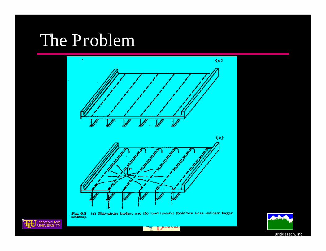
The Problem

BridgeTech, Inc.
Basics Behavior
Stiff Deckrelativeto Girders –betterdistribution,moreuniform
All analysis and numericalapproaches attempt to quantify this
behavior
Somewhere between Equal (Rigidbody)and
Lever Rule

BridgeTech, Inc.
AccuracySimplicity

BridgeTech, Inc.
AccuracySimplicity
BridgeTech, Inc.
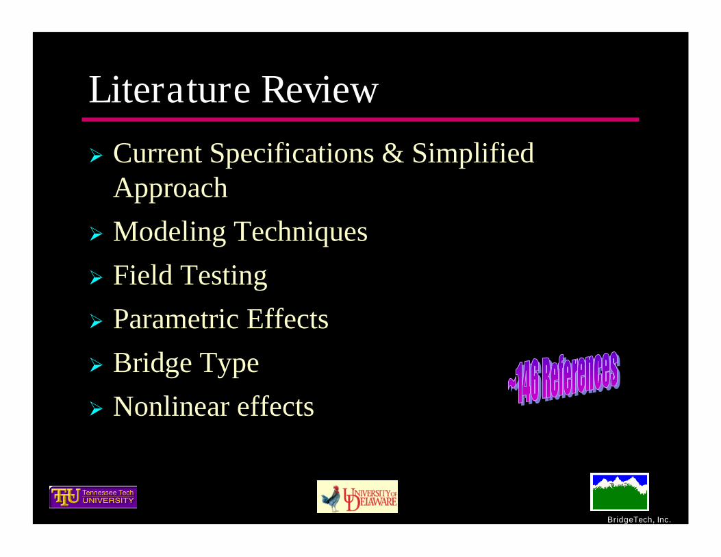
Literature ReviewCurrent Specifications & Simplified
ApproachModeling TechniquesField TestingParametric EffectsBridge TypeNonlinear effects

BridgeTech, Inc.
PI Bias for a Simple Method
• Analytically based approach
• Canadian SpecificationOrthotropic Plate Theoryspace

BridgeTech, Inc.
NBI 1990 - mostrecent
NBI TotalInventory Number Skewed
14275 6626330.0% 43.8%
1464 30753.1% 63.4%
1811 3546
3.8% 62.0%360 3677
0.8% 65.3%629 11340
1.3% 40.3%5329 9514
11.2% 53.6%
933 1396
2.0% 49.0%
40 82
0.1% 9.2%
208 300
0.4% 35.3%
208 300
0.4% 35.3%
14168 2669129.8% 50.1%
1571 42133.3% 15.8%
6799 20728
14.3% 37.1%47587 353845 150825
100.0% 42.6%
Precast Solid, Voided, orCellular Concrete Boxes withShear Keys and with orwithout TransversePosttensioning
Open Steel or PrecastConcrete Boxes
Cast-in-Place ConcreteMulticell BoxesCast-in-Place Concrete TeeBeamPrecast Solid, Voided, orCellular Concrete Boxes withShear Keys
Steel Beam Cast in place concreteslab, precast concrete
Closed Steel or PrecastConcrete Boxes
Cast in place concreteslab
Cast-in-place concrete orplank, glued/spiked panelsor stressed wood
Precast Concrete ChannelSections with Shear Keys
Precast Concrete DoubleTee Section with Shear Keysand with or withoutTransverse Posttensioning
Precast Concrete I or Bulb-Tee Sections
Precast Concrete TeeSection with Shear Keys andwith or without TransverseReinforcement
Integral Concrete
Integral Concrete
Cast-in-place concreteoverlay
Integral Concrete
Cast-in-place concrete,precast concrete
Cast-in-place concreteslab, precast concrete slab
Monolithic Concrete
Monolithic Concrete
Cast-in-place concreteoverlay
j
slab on girders
slab on girders
slab on girders
monolithic slab and girders
monolithic slab and girders
slab on girders
i
h
g
slab on girders
slab on girders
slab on girders
slab on girders
Supporting Components Type of DeckAASHTO Letter
(see Table4.6.2.2.1-1)
2848
a
d
c
b
f
e
Number of BridgesAnalytical Group Type
28106
17766
5718
5633
151398
Q
4847
slab on girders
53285
Slabs Not Applicable Not Applicable Slabs
26629
l
k
slab on girdersWood Beams
Total:
55869
895
851
851 NB
IDat
abas
e

BridgeTech, Inc.
Summary Table (NBI Data)
Type 1990-present Total Inventory
Steel Beam 30.0% 42.8%
Concrete I 29.8% 15.1%Precast ConcreteBoxes with Shear Keys 11.2% 5.0%
Slabs 14.3% 15.8%85.3% 78.7%
Bridge Percentages by Type

BridgeTech, Inc.
min. max min max min max min max min maxConc. T-Beam 71 n/a 12 93 2.42 16 5 11 0 52.98 0.32 3.26Steel I-Beam 163 n/a 12 205 2 15.5 4.42 12 0 66.1 0.4 4.53Prestressed I-Beam 94 n/a 18.75 136.2 3.21 10.5 5 9 0 47.7 0.31 3.12Prestressed Conc. Box 112 n/a 43.3 243 6 20.75 n/a n/a n/a n/a 0.52 8.13R/C Box 121 n/a 35.2 147 6.58 10.67 n/a n/a n/a n/a 0.53 5.5Slab 127 n/a 14.2 68 n/a n/a 9.8 36 0 70 0.21 2.56Multi-Box 66 n/a 21 112.7 n/a n/a 0 11 0 55.8 0.22 5.96Conc. Spread Box 35 n/a 29.3 136.5 6.42 11.75 6 8.5 0 52.8 0.54 3.11Steel Spread Box 20 n/a 58 281.7 8.67 24 5 9.5 0 60.5 0.75 8.02Precast Conc. Spread Box 4 1 - 6 44.38 81.49 5.67 13.75 7.75 8.75 0.00 48.49 1.68 2.03Precast Conc. Bulb-Tee 4 2 - 6 115.49 159.00 8.33 10.29 8.25 8.27 0.00 26.70 1.43 4.97Precast Conc. I-Beam 3 3 - 5 67.42 74.33 9.00 10.58 8.25 8.75 0.00 33.50 1.45 1.53CIP Conc. T-Beam 3 4 - 5 66.00 88.50 8.17 12.58 7.00 9.00 0.00 31.56 1.91 2.74CIP Conc. Multicell 4 2 - 3 98.75 140.00 9.00 10.33 8.00 9.25 0.00 26.23 2.24 3.05Steel I-Beam 4 2 - 4 140.00 182.00 9.33 11.50 8.00 9.00 0.00 50.16 1.60 5.11Steel Open Box 2 1 - 3 170.67 252.00 9.00 9.38 8.50 8.50 4.50 31.95 3.28 7.00
LRFR 3 653Slab on RC, Prest., andSteel Girders 653 1 - 7 18.00 243.00 2.33 18.00 0.00 8.00 N/A N/A 0.38 5.22
Spread Box Beams 27 1 100.00 190.00 5.00 20.00 6.00 12.00 N/A N/A 1.40 8.00
Adjacent Box Beams 23 1 100.00 210.00 3.00 5.83 5.00 6.00 N/A N/A 1.13 9.60
Slab on Steel I-Beam 24 1 160.00 300.00 12.00 20.00 9.00 12.00 N/A N/A 2.76 6.82
Summary: 1560 1 - 7 12.00 300.00 2.00 24.00 0.00 36.00 0.00 70.00 0.21 9.60
Span Length (ft)
ParametricBridges
N/A 74
Number ofSpans
Parameter RangesReference
Numberof
BridgesBridge TypesTotal No.
Bridges Aspect Ratio (L/W)Skew Angle (deg)Slab Thickness (in)Girder Spacing (ft)
24
809
Dat
aS
ou
rce
NCHRP 12-26
TN TechSet 1
1
2

BridgeTech, Inc.
CommonDatabaseFormatNCHRP 12-50
1. NCHRP 12-26 BridgeDatabase800 + Bridges can be used in anautomated process to generatesimplified and rigorous analyses.
3. Virtis/Opis DatabaseBridges650+ bridges may be exported fromVirtis/Opis to supply real bridges toboth simplified and rigorous methods.
2. Tenn. Tech. DatabaseDetailed descriptions and rigorousanalysis are available from a recentTT study for TN DOT. Results,structural models, etc., are readilyavailable.
Data Sources
Condense to aCommon Database
A
4. ParametricallyGenerated Bridges74 Bridges were developed totest the limits of applicability ofthe proposed method.

BridgeTech, Inc.
Rigorous Analysis (Basis)SAPAASHTO FE EngineAnsys
CommonDatabaseFormatNCHRP 12-50
Common DatabaseFormatNCHRP 12-50
A
B
BRASS-Girder (LRFD)TM
Simplified Analysis Methods: Standard Specifications (S over D) LRFD Specifications Rigid Method Lever Rule Adjusted Equal Distribution Method Canadian Highway Bridge Design Code Sanders

BridgeTech, Inc.
Simplified Moment and Shear Distribution Factor Equations Specification and Commentary Language Design Examples Final ReportIterative Process Involving Tasks 7,8, and 9 through 12.
Common DatabaseFormatNCHRP 12-50
Studies Directed Toward: Skew Lane Position Diaphragms
B
Comparisons and Regression Testing (NCHRP 12- 50 Process)Tasks 6 & 9Regression testing on “real” bridges (Virtis/Opis database, NCHRP 12-26 database)(compare proposed method to current LRFD method)Comparisons from parametric bridges and rigorous analysis

BridgeTech, Inc.
Grillage Method (structural model)

BridgeTech, Inc.
Influence Surfaces (structural model)

BridgeTech, Inc.
Automated Live Load Positioning
• Critical live load placement• Actions (shear, moment,reaction, translation)• Single and multiple lanesloaded• Critical longitudinalposition• Accounts for barrier, etc.• 4-ft truck transverse truckspacing• POI at least tenth points

BridgeTech, Inc.
Computation of Distribution Factor
/
rigorous
beam
Rigorous Action Number LanesDistribution Factor g
Action from Beamlinefor same Longitudinal Position
Mg
M

BridgeTech, Inc.
Using Distribution Factors
( )design rigorousestimate beamM M g

BridgeTech, Inc.
Example of Standard SpecificationResults
Moment at 1.4One-lane Loaded Exterior I-Girder
Std. S/D vs. Rigorous
y = 0.9914x + 0.2962R2 = 0.3834
0
0.2
0.4
0.6
0.8
1
1.2
1.4
0 0.2 0.4 0.6 0.8 1 1.2 1.4
Rigorous Distribution Factor
Std
.Spe
c.(S
/D)D
istr
ibu
tion
Fac
tor
1
1
Unit slope = good
R2 = poor
Poor R2 = littlehope

BridgeTech, Inc.
Lever Rule ResultsMoment at 1.4
One-lane Loaded Exterior I-GirderLever Rule vs. Rigorous
y = 1.63x - 0.2644R2 = 0.8889
0
0.2
0.4
0.6
0.8
1
1.2
1.4
0 0.2 0.4 0.6 0.8 1 1.2 1.4
Rigorous Distribution Factor
Lev
er
Ru
leD
istr
ibu
tion
Fac
tor 1
1
R2 = good
slope = poor
Apply affinetransformation

BridgeTech, Inc.
Moment at 1.4One-lane Loaded Exterior I-GirderCalibrated Lever Rule vs. Rigorous
y = 0.978x + 0.0413R2 = 0.8889
0
0.2
0.4
0.6
0.8
1
1.2
1.4
0 0.2 0.4 0.6 0.8 1 1.2 1.4
Rigorous Distribution Factor
Cal
ibra
ted
Lev
erR
ule
Dis
trib
utio
nFa
cto
r
1
1
Calibrated Lever Rule Results
R2 = good and is thesame
slope = good
BridgeTech, Inc.
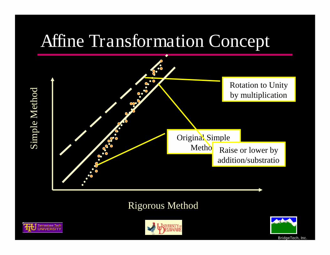
Affine Transformation ConceptSi
mpl
eM
etho
d
Rigorous Method
Original SimpleMethod
Rotation to Unityby multiplication
Raise or lower byaddition/substratio
n

BridgeTech, Inc.
Affine Transformation (example)
1 1.63 0.2644y x 12
1.63 0.26440.1622
1.63 1.63 1.63y x
y x
13 2 0.1622 0.1622 0.1622 0.1622
1.63y
y y x x
( )
( )
( )
where1
0.61 and 0.16221.63
andis thecalibrated distribution factor, and
is the lever ruledistribution factor computed with the typical man
Calibrated lever rule m Lever rule m
m m
Calibrated lever rule
Lever rule
g a g b
a b
g
g
ualapproach.
Unitslope
Unitslope

BridgeTech, Inc.
Affine Transformation ConceptSi
mpl
eM
etho
d
Rigorous Method

BridgeTech, Inc.
Number ofLoadedLanes
Girder Distribution Factor Multiple Presence Factor
Use integer part of
m shall be greater than or equal to 0.85.
to determine number of loaded lanes formultiple presence.
Interior andExterior
Two ormore
LoadedLanes
m = 1.2Interior andExterior
One
10c st L
m ag g
W F Nmg m m
N N
12cW
Lm m lever rule m
g
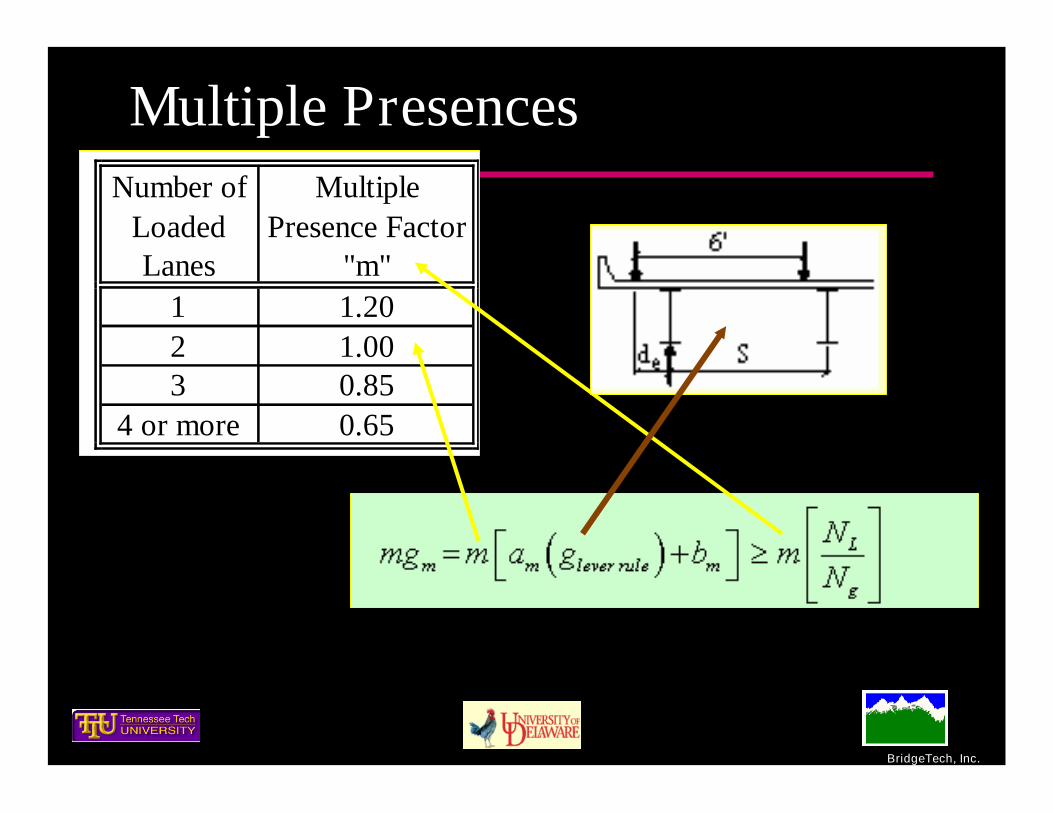
Nmg m a g b m
N
Moment Distribution Factor Computation
BridgeTech, Inc.
Multiple Presences
1 1.202 1.003 0.85
4 or more 0.65
Number ofLoadedLanes
MultiplePresence Factor
"m"

BridgeTech, Inc.
Lever Rule Equations (aids)Girder
Location
Numberof Loaded
Lanes Distribution Factor Range of Application Loading Diagram
Numberof Wheelsto Beam
2
2
3
4
1
1
2 or more
Exterior
12 2
edS
6e
e
d S ft
d S
31 ed
S S 6ed S ft
31 ed
S S 10ed S ft
33 82 2
edS S
10 16ed S ft
16 20ed S ft ed S
6'6' 4'
ed S
6' 6'4'
ed S
6'6' 4'
S
ed S
6'
Sde
6'
2 162 ed
S S

BridgeTech, Inc.
Calibration Coefficients (Moment)
a m b m a m b mSteel I-Beam aPrecast Concrete I-Beam kPrecast Concrete Bulb-Tee Beam kPrecast Concrete Double Tee withShear Keys with or without Post-Tensioning
i
Precast Concrete Tee Section withShear Keys and with or withoutTransverse Post-Tensioning
j
Precast Concrete Channel with ShearKeys h
Cast-in-Place Concrete Tee Beam e 0.65 0.15 1.40 -0.41Cast-in-Place Concrete Multicell BoxBeam
d
Adjacent Box Beam with Cast-in-Place Concrete Overlay
f
Adjacent Box Beam with IntegralConcrete g
Precast Concrete Spread Box Beam b, c 0.50 0.06 0.77 -0.17Open Steel Box Beam c Use Article 4.6.2.2.3
Moment
1.51 -0.690.41 -0.03
1.20 -0.370.61 0.16
Structure Type
AASHTOLRFD CrossSection Type
One Loaded LaneExterior Interior
BridgeTech, Inc.
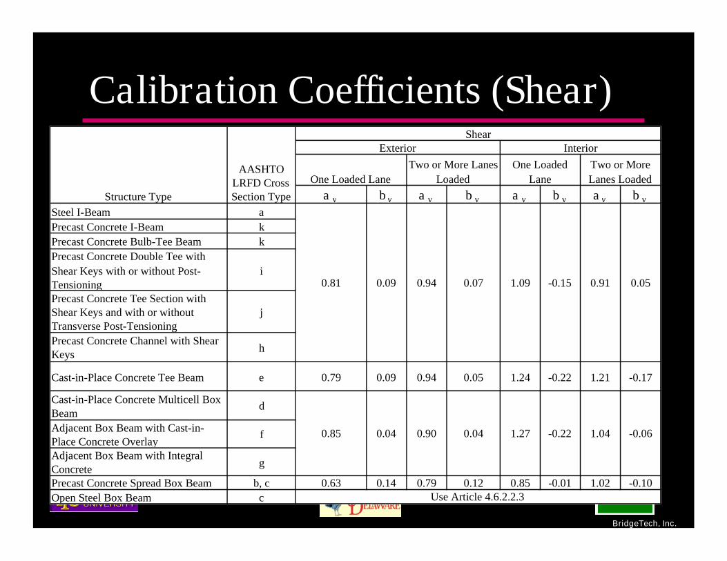
Calibration Coefficients (Shear)
a v b v a v b v a v b v a v b v
Steel I-Beam aPrecast Concrete I-Beam kPrecast Concrete Bulb-Tee Beam kPrecast Concrete Double Tee withShear Keys with or without Post-Tensioning
i
Precast Concrete Tee Section withShear Keys and with or withoutTransverse Post-Tensioning
j
Precast Concrete Channel with ShearKeys h
Cast-in-Place Concrete Tee Beam e 0.79 0.09 0.94 0.05 1.24 -0.22 1.21 -0.17
Cast-in-Place Concrete Multicell BoxBeam
d
Adjacent Box Beam with Cast-in-Place Concrete Overlay
f
Adjacent Box Beam with IntegralConcrete g
Precast Concrete Spread Box Beam b, c 0.63 0.14 0.79 0.12 0.85 -0.01 1.02 -0.10Open Steel Box Beam c Use Article 4.6.2.2.3
Structure Type
AASHTOLRFD CrossSection Type
ShearExterior Interior
One Loaded LaneTwo or More Lanes
LoadedOne Loaded
LaneTwo or MoreLanes Loaded
0.81 0.09 0.94 0.07
0.85 0.04 0.90 0.04 -0.06
1.09 -0.15 0.91
1.27 -0.22 1.04
0.05

BridgeTech, Inc.
Structural Factor (Moment) MultipleLanes Loaded
Steel I-Beam aPrecast Concrete I-Beam kPrecast Concrete Bulb-Tee Beam kPrecast Concrete Double Tee withShear Keys with or without Post-Tensioning
i
Precast Concrete Tee Section withShear Keys and with or withoutTransverse Post-Tensioning
j
Precast Concrete Channel with ShearKeys h
Cast-in-Place Concrete Tee Beam e 1.10Cast-in-Place Concrete Multicell BoxBeam d
Adjacent Box Beam with Cast-in-Place Concrete Overlay f
Adjacent Box Beam with IntegralConcrete g
Precast Concrete Spread Box Beam b, c 1.00
Open Steel Box Beam cUse ExistingSpecification
Structure Type
AASHTOLRFD CrossSection Type
Two or moreloaded lanes
1.15
1.10
F st
UniformDistribution
Nlane / Ngirder

BridgeTech, Inc.
Example
10’4’
2’ 6’
6 120.9
2 10 2 100.9
0.61 0.9 0.16
0.71
exterior
Lever Rule
Calibrated m Lever Rule m
Calibrated
P PR P
g
g a g b
g
P/2 P/2

BridgeTech, Inc.
Calibration ResultsSlab-on-Girder Bridges
Type of Bridge
Slope Intercept R 2Figures a b a or F st b
RegressionPlot R 2
1 Lane 1.2386 -0.1112 0.9661 13a, N-125 0.8074 0.0898 0.81 0.09 13b, K-16 0.9656
2 or More Lanes 1.0657 -0.0713 0.9674 14a, N-117 0.9384 0.0669 0.94 0.07 14b, K-15 0.9485
1 Lane 0.9209 0.1355 0.9198 15a, N-93 1.0859 -0.1471 1.09 -0.15 15b, K-12 0.9198
2 or More Lanes 1.1041 -0.0553 0.9343 16a, N-85 0.9057 0.0501 0.91 0.05 16b, K-11 0.9343
CalibratedLever 1 Lane 1.6396 -0.2679 0.8894 17a, N-61 0.6099 0.1634 0.61 0.16 17b, K-8 0.8894
Henry'sMethod 2 or More Lanes 1.0440 0.1098 0.8757 18a, N-51 n/a n/a 1.15 n/a 18b, K-7 0.8757
CalibratedLever 1 Lane 0.8346 0.3076 0.4497 19a, N-29 1.1982 -0.3686 1.20 -0.37 19b, K-4 0.4508
Henry'sMethod 2 or More Lanes 1.0112 0.0658 0.9216 20a, N-19 n/a n/a 1.15 n/a 20b, K-3 0.9216
I-G
irder
s(a
,h,i
,j,k
)
Shea
r
CalibratedLever
Exterior
Interior
Mom
ent
Exterior
Interior
GirderLocationAction
BasicMethod
Calibration Constants
Lanes LoadedInitial Trend Line - Lever Rule and Henry'sMethod (Henry's Method already calibrated)
Computed CalibrationFactors (for LeverRule Calibration)
Recommended Calibration Factors
QuiteGood
(typical)

BridgeTech, Inc.
Statistical Comparison Conceptual
1.00
Standarddeviation
simplified
rigorous
g
g
Num
ber
ofSa
mpl
es
Mean

BridgeTech, Inc.
Shift Simple Upward by a factor
Simple / Rigorous1.00
Increase by a factor that isrelated to the COV
a

BridgeTech, Inc.
Analysis FactorsType of Bridge
No. ofStd. Dev.
Offset
ComputedAnalysisFactor
RoundedAnalysis Factor
( b = 1)
No. of Std.Dev. Offset
ComputedAnalysis Factor
RoundedAnalysis Factor
(b = 0.5)
No. of Std. Dev.Offset
ComputedAnalysisFactor
RoundedAnalysis
Factor (b =S/R (S/R) -1 V S/R β ga ga (rounded) β ga ga (rounded) β ga ga (rounded)
1 Lane 13c 1.010 0.991 0.058 1.0 1.049 1.05 0.5 1.020 1.05 0.0 0.991 1.002 or More Lanes 14c 1.014 0.986 0.067 1.0 1.053 1.05 0.5 1.019 1.05 0.0 0.986 1.001 Lane 15c 0.999 1.001 0.069 1.0 1.069 1.10 0.5 1.035 1.05 0.0 1.001 1.002 or More Lanes 16c 1.000 1.000 0.102 1.0 1.102 1.10 0.5 1.051 1.05 0.0 1.000 1.00
CalibratedLever
1 Lane 17c 0.993 1.007 0.0921.0 1.099 1.10 0.5 1.053 1.05 0.0 1.007 1.00
Henry'sMethod 2 or More Lanes 18c 1.285 0.778 0.110 1.0 0.888 1.00 0.5 0.833 0.85 0.0 0.778 0.80
CalibratedLever
1 Lane 19c 0.996 1.004 0.244 1.0 1.248 1.25 0.5 1.126 1.15 0.0 1.004 1.00Henry'sMethod
2 or More Lanes 20c 1.139 0.878 0.068 1.0 0.945 1.00 0.5 0.912 0.95 0.0 0.878 0.90
FiguresAction
Interior
Exterior
Girder LocationBasic
Method
Interior
Exterior
CalibratedLeverS
hear
No. of Std. Dev. Offset b = 1 No. of Std. Dev. Offset b = 0.5 No. of Std. Dev. Offset b = 0.0
I-G
irde
rs(a
,h,
i,j,
k)
COVInverseRatio ofMeansLanes Loaded
Analysis Factor Computations
Mo
men
t
High dueto highCOV

BridgeTech, Inc.
Example Continued
6 120.9
2 10 2 100.9
0.61 0.9 0.16
0.71
exterior
Lever Rule
Calibrated m Lever Rule m
Calibrated
P PR P
g
g a g b
g
0.71
1.05 1.2 0.71
0.89
Calibrated
a
a
g g
mg
mg
PreviousExample

BridgeTech, Inc.
All effects are now separated anunderstandable
1.05 1.2 0.71
0.89a
a
mg
mg
Variability in
analysis
Effect of MultiplePresence
Analysis

BridgeTech, Inc.
SkewAdjustments for shearNo iterationCommentary M&M 20-07 StudyNeglect decrease for moment

BridgeTech, Inc.
CurvatureNo change

BridgeTech, Inc.
Type of SuperstructureApplicable Cross-Section
from Table 4.6.2.2.1-1 Correction Factor
Range of
Applicability
Concrete Deck, Filled Grid,Partially Filled Grid, or UnfilledGrid Deck Composite withReinforced Concrete Slab on Steelor Concrete Beams; Concrete T-Beams, T- and Double T-Section
a, e and also h, i, j
if sufficiently connected toact as a unit
1.0 0.20 tan 0 603.5 16.020 240
4b
SL
N
Precast concrete I and bulb teebeams
K 1.0 0.09 tan 0 603.5 16.020 240
4b
SL
N
Cast-in-Place Concrete MulticellBox
D 12.01.0 0.25 tan
70L
d
0 60
6.0 13.020 240
35 1103c
SL
dN
Concrete Deck on Spread ConcreteBox Beams
B, c
12.01.0 tan6
Ld
S
0 60
6.0 11.520 140
18 653b
SL
dN
Concrete Box Beams Used inMultibeam Decks
f, g 12.01.0 tan
90L
d
0 6020 120
17 6035 60
5 20b
L
db
N

BridgeTech, Inc.
Push-the-limits bridgesW
SSOverhang
1'-9"
OverhangS
st
1'-9"
BridgeNo.
GirderSpacing,
S(ft)
Recommendedminimum slab
thickness(AASHTO STD
Table 8.9.2)
SlabThickness,
ts
(in)
SpanLength, L
(ft)
TotalBridge
Width, W(ft)
No.ofgirders
Overhang(ft)
1 12 8.80 9.00 240 44 4 42 12 8.80 9.00 260 44 4 43 12 8.80 9.00 280 44 4 44 12 8.80 9.00 300 44 4 45 12 8.80 9.00 200 44 4 46 14 9.60 9.75 200 48 4 37 16 10.40 10.50 200 54 4 38 18 11.20 11.25 200 60 4 39 20 12.00 12.00 200 68 4 410 12 8.80 9.00 160 58 5 511 12 8.80 9.00 160 53 4 8.5

BridgeTech, Inc.
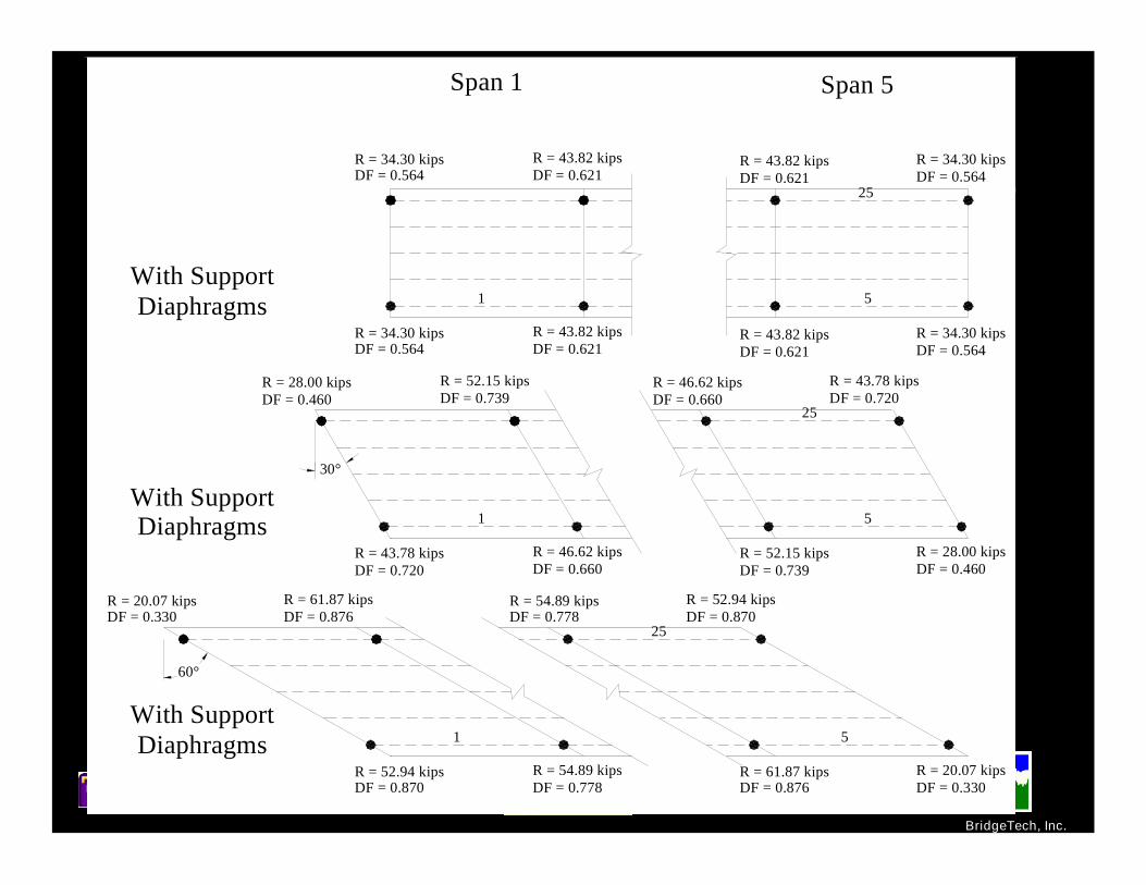
Many Parameter StudiesSkew
Diaphragm Cross-frame Stiffness End Cross-frames Intermediate Cross-frames
Typical Example
BridgeTech, Inc.
With SupportDiaphragms
With SupportDiaphragms
With SupportDiaphragms
R = 61.87 kipsDF = 0.876
R = 52.94 kipsDF = 0.870
R = 54.89 kipsDF = 0.778
R = 20.07 kipsDF = 0.330
R = 52.94 kipsDF = 0.870
R = 43.82 kipsDF = 0.621
R = 52.15 kipsDF = 0.739
R = 43.78 kipsDF = 0.720
1
1
1
R = 54.89 kipsDF = 0.778
R = 46.62 kipsDF = 0.660
25
R = 46.62 kipsDF = 0.660
Span 1
5
5
R = 28.00 kipsDF = 0.460
R = 43.78 kipsDF = 0.720
25
5
Span 5
25
R = 34.30 kipsDF = 0.564
60°
30°
R = 34.30 kipsDF = 0.564
R = 43.82 kipsDF = 0.621
R = 34.30 kipsDF = 0.564
R = 34.30 kipsDF = 0.564
R = 43.82 kipsDF = 0.621
R = 43.82 kipsDF = 0.621
R = 28.00 kipsDF = 0.460
R = 52.15 kipsDF = 0.739
R = 20.07 kipsDF = 0.330
R = 61.87 kipsDF = 0.876

BridgeTech, Inc.
Regression TestingComplete database used to compare:
LRFD S/D Rigorous Again, used 12-50

BridgeTech, Inc.
Is this simpler?
Consistent approach for most bridgetypes
Based upon lever rule (shear and one-lane moment) – and adjusted
Based uniform distribution (multiple-lanes loaded – and adjusted
Independently accounts for multiplepresence

BridgeTech, Inc.
Is this simpler?Independently accounts for variability of
simple analysis wrt rigorousLever rule aids are provided in appendixNo iterative approach, i.e., independent of
cross section and span lengthsSame for positive and negative moment
areasSkew corrections are based upon S/L
(readily known)

BridgeTech, Inc.
Is it simpler?
Many pages shorterMany variables eliminated from
notation and sectionOnce affine transformations are
understood the adjustments fromlever are readily seen

BridgeTech, Inc.
Go to report
BridgeTech, Inc.
Additional work
Recalibrate uniform method parallel thecalibrated lever
Improve one-lane loaded for momentReview/revise tub girder systems
Develop presentation materials to helpexplain this in a more understandable manner
Suggestions welcome!

BridgeTech, Inc.
Questions, Discussion

BridgeTech, Inc.
End of AASHTO Talk

BridgeTech, Inc.
Extra slides

BridgeTech, Inc.
Modeling Appendix
hh1
h2
le1
le2
li/2
li/2
li
il
tw
t1
2t
hs
twCentroid Axisof Box-Girder
ExteriorLongitudinal
Girder
InteriorLongitudinal
Girder
h
l e1
e2l
il
l e* Interior
LongitudinalGirder
ExteriorLongitudinal
Girder
Closed Section ForTorsional Rigidity

BridgeTech, Inc.
Shear Distribution Factors for CIP Concrete Multicell
Box Beam Bridges -- Validation
Ext Int Exterior Interior Exterior Interior Exterior Interior1 L 0.620 0.344 0.618 0.338 0.29% 1.84%2 L 0.644 0.876 0.644 0.889 0.06% 1.45%3 L 0.654 0.900 0.653 0.915 0.25% 1.69%1 L 0.618 0.346 0.620 0.336 0.34% 3.03%2 L 0.637 0.885 0.640 0.891 0.51% 0.68%3 L 0.645 0.904 0.649 0.913 0.57% 0.93%1 L 0.643 0.317 0.639 0.310 0.63% 2.08%2 L 0.669 0.861 0.664 0.815 0.80% 5.36%3 L 0.679 0.885 0.672 0.877 1.00% 0.95%1 L 0.635 0.318 0.547 0.289 13.84% 9.10%2 L 0.667 0.854 0.606 0.759 9.06% 11.18%3 L 0.679 0.883 0.629 0.817 7.37% 7.50%1 L 0.722 0.264 0.718 0.257 0.43% 2.52%2 L 0.774 0.955 0.780 0.948 0.70% 0.65%3 L 0.779 1.022 0.784 1.033 0.67% 1.02%1 L 0.706 0.267 0.698 0.261 1.17% 2.26%2 L 0.767 0.941 0.769 0.930 0.15% 1.18%3 L 0.776 1.016 0.778 1.022 0.24% 0.63%1 L 0.652 0.317 0.658 0.314 0.88% 0.95%2 L 0.675 0.914 0.681 0.936 0.83% 2.40%1 L 0.642 0.319 0.645 0.335 0.43% 5.12%2 L 0.671 0.908 0.675 0.983 0.62% 8.30%
SAP2000 BTLiveLoader DifferenceBridgeType
TTUBridge No.
BridgeID No. Span LanesLoaded
BeamEnd
1
210141013
2
1
14 1011 1012
2
13
15
Mul
ticel
lBox
Bea
m
1
2
12 1007 1008
10101009
1

BridgeTech, Inc.
excellent ≥0.9 bad < 0.5
Lever Rule Henry'sMethod
LRFD CHBDC STD Sanders BestMethod
1 excellent good good bad bad bad Lever2 or more excellent acceptable good bad bad bad Lever
1 excellent poor good good good good Lever2 or more excellent excellent excellent good good good Lever
1 good good good bad bad bad Lever2 or more good good good poor acceptable bad Lever
1 bad bad bad bad bad bad CHBDC2 or more acceptable excellent acceptable acceptable acceptable poor Henry's
1 excellent good good poor poor poor Lever2 or more excellent excellent excellent poor poor poor Lever
1 excellent poor excellent excellent good good Lever2 or more good excellent good excellent good excellent Henry's
1 excellent excellent good poor poor poor Henry's2 or more excellent excellent excellent poor poor poor Henry's
1 poor bad excellent acceptable poor poor LRFD2 or more poor excellent excellent good good good Henry's
1 excellent acceptable excellent poor acceptable bad Lever2 or more excellent excellent excellent acceptable acceptable poor Lever
1 excellent acceptable excellent acceptable good poor Lever2 or more good excellent excellent good excellent poor Henry's
1 poor poor poor poor poor poor CHBDC2 or more good excellent good poor acceptable poor Henry's
1 acceptable bad poor bad poor bad Lever2 or more poor excellent poor bad poor bad Henry's
1 excellent poor excellent acceptable acceptable poor Lever2 or more excellent excellent excellent good good acceptable Lever
1 excellent poor acceptable good excellent acceptable STD2 or more excellent excellent excellent good excellent acceptable Henry's
1 poor bad bad poor bad bad CHBDC2 or more acceptable good poor poor poor bad Henry's
1 bad excellent bad poor bad bad Henry's2 or more poor good poor poor poor bad Henry's
Method Rating Based on the Value of the Correlation Coefficient (R2) between Each SimplifiedMethod and Rigorous Analysis
LanesLoaded
GirderLocations
ActionBridgeSet
Method0.90 > good ≥0.80 0.80 > acceptable ≥0.70 0.70 > poor≥0.50
4
3
2
1
Moment
Moment
Shear
Moment
Shear
Moment
Shear
Shear
Exterior
Interior
Exterior
Interior
Exterior
Interior
Exterior
Interior
Exterior
Interior
Exterior
Interior
Exterior
Interior
Exterior
Interior
Slab On I
CIP Tees
SpreadBoxes
AdjacentBoxes
vvcc
vvcccvc
vvcc

BridgeTech, Inc.
Basics Continued Deflection is the easiest state
variable to predictanalytically/numerically
Interior girder load effects areeasier to predict than exterior
Loads near midspan distributemore uniformly than loadapplied near supports.
Relative stiffness is primaryand flexure is more importantthan is torsion
Most important parameter isthe girder spacing (orcantilever span)
2
2
3
3
( )
( )
d wEI M x
dxd w
EI V xdx

BridgeTech, Inc.
Prerequisites We are not proposing to take any one simplified
method “as is”. (unless it really works well). Analytically-based approaches can be
implemented at different levels (i.e., computestiffness parameters) – empirical methods cannot.
Analytically-based approaches can be more easilyextended (in case of limits of application), thanempirically-based methods.
Analytically-based approaches can be as simple asempirical approaches

BridgeTech, Inc.
Task 1 -- Literature Review
Michael PatritchGraduate StudentTN Tech

BridgeTech, Inc.
Task 1 -- Literature Critical Findings
Simplified methods Sanders and Elleby “Equal Distribution Method” – name is a
misnomer Canadian Standards Juxtaposition of stiffness extremes
Stiffness effectsTestingAnalysis and modeling

BridgeTech, Inc.
Sanders and Elleby NCHRP study Limitations
Span to 120-ft Slab on Beam (Orthotropic Plate Theory) Multi beam (Articulated Orthotropic Plate) CIP Boxes (Folded Plate)
Considered Aspect ratio Relative long/trans flexural stiffness Relative torsonal stiffness
Field tests for some validation

BridgeTech, Inc.
AASHTO LRFD NCHRP 12-26 Empirically based Includes stiffness parameters in equations “Ugly” equations Embedded multiple presence factors No rational analytical basis Resort to lever rule when empiricism fails Works reasonably well for interior girders Limitations are of concern

BridgeTech, Inc.
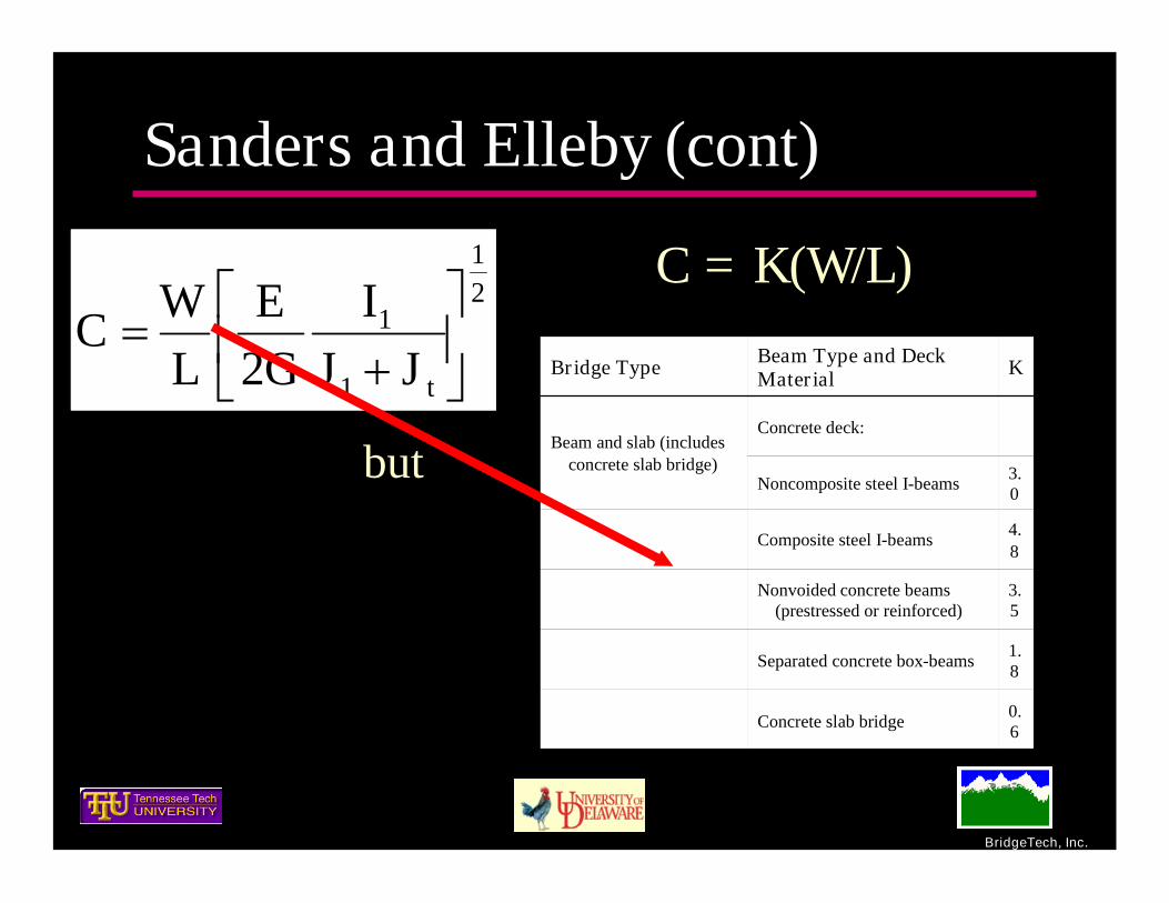
Sanders and Elleby (cont)
3For10
5
3For3
17
23
105
/2
CN
D
CCNN
D
DSg
L
LL
DSwheelg /)( Double for
LFRDDesign Lane

BridgeTech, Inc.
Equal Distribution Method (TN DOT)
All beams carry equal live load(interior/exterior)
g = NL/Ng
Interpolate number of lanesAdjust g by empirical factors from researchResearch is on interior beamsSimple but purely empiricalLimited sample for rigorous comparison

BridgeTech, Inc.
TN DOT Equal Distribution Method
BridgeTech, Inc.
Sanders and Elleby (cont)
21
1
1
2
tJJ
IGE
LW
C
0.6Concrete slab bridge
1.8Separated concrete box-beams
3.5
Nonvoided concrete beams(prestressed or reinforced)
4.8
Composite steel I-beams
3.0Noncomposite steel I-beams
Concrete deck:Beam and slab (includes
concrete slab bridge)
KBeam Type and DeckMaterialBridge Type
C = K(W/L)
but

BridgeTech, Inc.
Canadian SpecificationAnalytically based upon orthotropic plate
theoryVery similar to Sanders and EllebyUse either stiffness parameter approach or
good estimation tables (easy)Few limitationsMore rational limits for skew and curvature

BridgeTech, Inc.
Canadian Specification (cont) Slab Voided slab, including multi-cell box girders with sufficient
diaphragms, Slab-on-girders Steel grid deck-on-girders Shear-connected beam bridges in which the interconnection of
adjacent beams is such as to provide continuity of transverse flexuralrigidity across the cross-section
Box girder bridges in which the boxes are connected by only the deckslab and transverse diaphragms, if present
Shear-connected beam bridges in which the interconnection ofadjacent beams is such as not to provide continuity of transverseflexural rigidity across the cross-section
Numerous wood systems ….

BridgeTech, Inc.
Canadian Specification (cont)
gNmMn
M Laneavgg
avggmg MFM
1001001 ef
mCC
F
NSF

BridgeTech, Inc.
Canadian Specification (cont)
1001001 ef
mCC
F
NSF
LengthSpanKCF
Lane width effect
Lane position effect

BridgeTech, Inc.
Canadian Specification (cont)Similar procedures for shear – different values

BridgeTech, Inc.
Canadian Specification (cont)Skew limit
Plan View
BeamsonSlab
Slabs
LengthSpanangleskewWidthBridge
181
61
)tan(

BridgeTech, Inc.
Canadian Specification (cont)
0.12
CurvatureofRadiusb
LengthSpan

BridgeTech, Inc.
Kennedy and SennahSteel BoxesPossibly concrete with modificationsSimilar to LRFD approach (authors claim
better accuracy)Empirical “Ugly” equations

BridgeTech, Inc.
European Practice
BridgeTech, Inc.
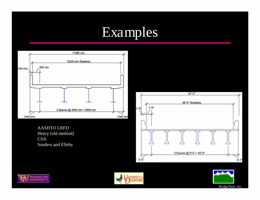
Examples
AASHTO LRFDHenry (old method)CSASanders and Elleby

BridgeTech, Inc.
Summary
Moment Shear Moment Shear Moment Shear Moment Shear
AASHTO LRFD 0.694 0.955 0.840 0.840 0.732 0.884 0.733 0.733Canadian Bridge Design Code 0.895 0.895 1.034 1.034 0.783 0.783 0.930 0.930Sanders and Elleby 0.710 0.710 0.710 0.710 0.946 0.946 0.946 0.946Equal Distribution Factor Method 0.774 0.774 0.774 0.774 0.655 0.655 0.655 0.655
Interior ExteriorPCI Example 4
Interior ExteriorMethodAISI Example 2

BridgeTech, Inc.
Task 2 – Range of structural forms, materialsand range of application
Range of application There is no reason at this point to limit range of
application (we can include range outside ofconventional practice and geometries)
“All” parameters will be included in thedatabase
A large amount of data is available fromseveral sources (see Task 6 tables)
Additional data can be added
BridgeTech, Inc.
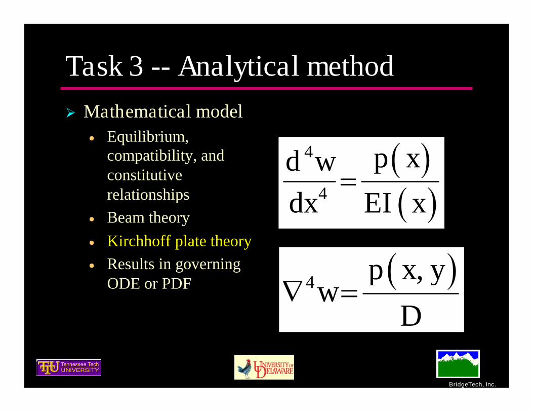
Task 3 -- Analytical method Mathematical model
Equilibrium,compatibility, andconstitutiverelationships
Beam theory Kirchhoff plate theory Results in governing
ODE or PDF
4
4
p xd wdx EI x
4 ,p x yw
D

BridgeTech, Inc.
Task 3 -- Analytical methodNumerical methods
Finite difference Finite element method (plate or shell elements) Grillage Finite Strip Method Harmonic analysis (Sanders and Elleby)

BridgeTech, Inc.
Theorem Requirements
Calculated internal actions and appliedforces are in equilibrium
Materials and section/member behaviormust be ductile
Independent of themodeling assumptions!
No instability or fracture

BridgeTech, Inc.
The lower bound theorem isone of the most importanttheorems/concepts instructural engineering.

BridgeTech, Inc.
The lower bound theorem isone of the most importanttheorems/concepts instructural engineering.
Offers wonderful assurance as the modelsare often simple approximations to thereal world.
BridgeTech, Inc.
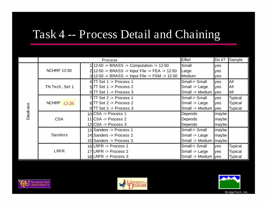
Task 4 -- Process Detail and Chaining
Effort Do it? Sample1 12-50 -> BRASS -> Computation -> 12-50 Small yes2 12-50 -> BRASS -> Input File -> FEA -> 12-50 Large yes3 12-50 -> BRASS -> Input File -> FSM -> 12-50 Medium yes4 TT Set 1 -> Process 1 Small-> Small yes All5 TT Set 1 -> Process 2 Small -> Large yes All6 TT Set 1 -> Process 3 Small -> Medium yes All7 TT Set 2 -> Process 1 Small-> Small yes Typical8 TT Set 2 -> Process 2 Small -> Large yes Typical9 TT Set 2 -> Process 3 Small -> Medium yes Typical
10 CSA -> Process 1 Depends maybe11 CSA -> Process 2 Depends maybe12 CSA -> Process 3 Depends maybe13 Sanders -> Process 1 Small-> Small maybe14 Sanders -> Process 2 Small -> Large maybe15 Sanders -> Process 3 Small -> Medium maybe16 LRFR -> Process 1 Small-> Small yes Typical17 LRFR -> Process 2 Small -> Large yes Typical18 LRFR -> Process 3 Small -> Medium yes Typical
Process
NCHRP 12-50
Dat
abas
e
LRFR
Sanders
CSA
NCHRP 12-62
TN Tech, Set 1
12-26
BridgeTech, Inc.
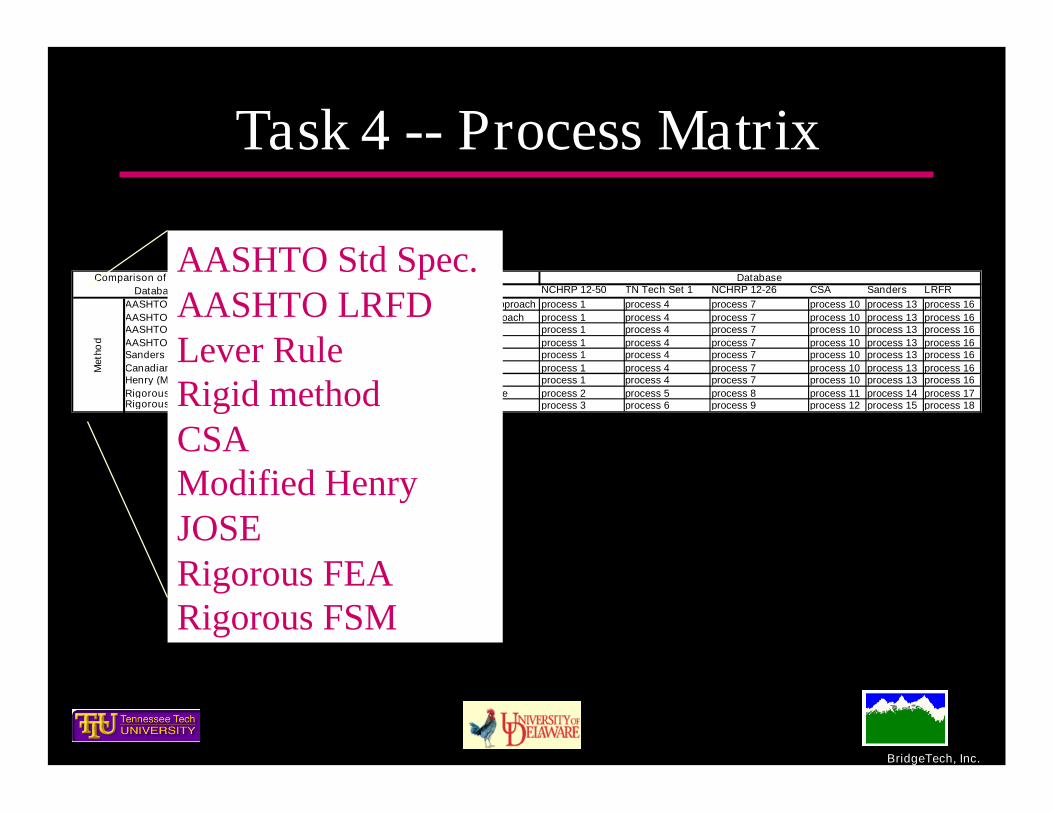
Task 4 -- Process Matrix
Notes NCHRP 12-50 TN Tech Set 1 NCHRP 12-26 CSA Sanders LRFRAASHTO Std S/D equation, program into an automated approach process 1 process 4 process 7 process 10 process 13 process 16AASHTO LRFD LRFD Eqs, program into an automated approach process 1 process 4 process 7 process 10 process 13 process 16AASHTO LRFD Lever Rule Program into an automated approach process 1 process 4 process 7 process 10 process 13 process 16AASHTO LRFD Rigid Method Program into an automated approach process 1 process 4 process 7 process 10 process 13 process 16Sanders Program into an automated approach process 1 process 4 process 7 process 10 process 13 process 16Canadian Specification (CSA) Program into an automated approach process 1 process 4 process 7 process 10 process 13 process 16Henry (Modified) Program into an automated approach process 1 process 4 process 7 process 10 process 13 process 16Rigorous FEA FEA engine and/or a commercial FEA engine process 2 process 5 process 8 process 11 process 14 process 17Rigorous FSM Available FSM program process 3 process 6 process 9 process 12 process 15 process 18
Met
hod
Comparison of Methods and AvailableDatabases of Bridges
DatabaseAASHTO Std Spec.AASHTO LRFDLever RuleRigid methodCSAModified HenryJOSERigorous FEARigorous FSM

BridgeTech, Inc.
Task 6 – Parametric StudySlab on Steel Girders
321 Total Data Sets AASHTO Type A

BridgeTech, Inc.
Task 6 – Parametric StudySlab on Precast I and Bulb Tee Girders
176 Total Data Sets AASHTO Type K

BridgeTech, Inc.
Task 6 – Parametric StudySlab on Concrete Tees
74 Total Data Sets AASHTO Types E and J

BridgeTech, Inc.
Task 6 – Parametric StudySlab Bridges – 127 Slab Data Sets

BridgeTech, Inc.
Task 6 – Parametric Study Spread Concrete Boxes
94 Total Data Sets AASHTO Types B and C

BridgeTech, Inc.
Task 6 – Parametric StudyAdjacent Concrete Boxes
307 Total Data Sets AASHTO Types D, F, and G

BridgeTech, Inc.
Task 6 -- Wood BridgesWood bridges will not be addressed

BridgeTech, Inc.
Additional Load Distribution Issues
Parameters Skew Barriers Diaphragms LocationSkew Yes Maybe Yes MaybeBarriers Maybe Yes Maybe YesDiaphragms Yes Maybe Yes MaybeLocation (e.g. Fatigue) Maybe Yes Maybe Yes
Additional Parameters
Perform separate parametric studies to focusexclusively on these effects

BridgeTech, Inc.
Three primary questions for thepanel
Lane width to determine the number oflanes
Live load positionMultiple presence factors

BridgeTech, Inc.
Number of Lanes Loaded
•Issue for ourstudy – not totaldesign load forgirder systems
•Integer numberor decimal value
•Should not beoverly sensitive tothe distributionfactor

BridgeTech, Inc.
Live Load Position – Interior Girder
6-4-6-6 (critical)
6-4-6-4-6 (critical)
6-6-6-6-6 (critical)
BridgeTech, Inc.
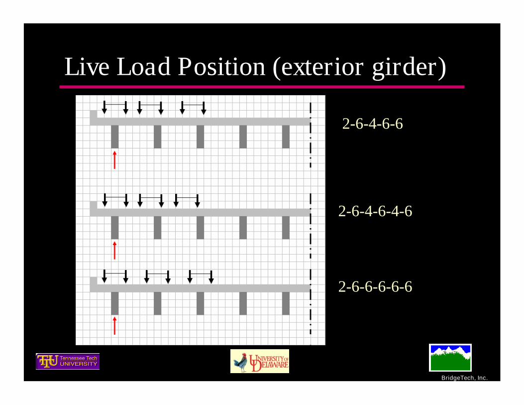
Live Load Position (exterior girder)
2-6-4-6-6
2-6-4-6-4-6
2-6-6-6-6-6

BridgeTech, Inc.
Multiple Presence – separate fromlive load distribution
Task 6 distribution factors will be computed forone-, two-, three-, etc-lanes loaded. This could becombined, if necessary, later.
Research simplified methods will not include m. Rearch simplified methods will permit one-, two-,
three-, etc-lanes loaded to be computed andindependently applied.
The specification can clearly indicate (apriori)how the number of controlling lanes, i.e., it can beexplicit and simple.

BridgeTech, Inc.
Example
0.65
0.85
1.0
1.2
MultiplePresenceFactor
z.Z3
w.W4 or more
y.Y2
x.X1
FactorRequired byMethod
Number oflanes loaded
Controls for Strength I