simplified ip addressing technical note - opto...
TRANSCRIPT

OPTO 22 • 800-321-6786 • 1-951-695-3000 • www.opto22.com • [email protected]
© 2004-2019 Opto 22. All rights reserved. Dimensions and specifications are subject to change. Brand or product names used herein are trademarks or registered trademarks of their respective companies or organizations.
PAGE 1
Form 1362-190823Simplified IP Addressing
By Gene E. Hector (Used by permission)
Some years back when I was teaching Novell courses I noted that too many students in my TCP/IP course were
having problems understanding IP addressing. Other instructors were having the same results. Although I
walked the students through the material very carefully, I found that many of them had difficulty grasping the
concepts. Furthermore, the problem was exacerbated by them having to take the CNE tests which were
closed book and timed. Hence, they needed a quick and effective way of working with IP addresses.
So I fine-tuned an approach that would minimize the chances for test errors and help them memorize and
apply the principles at almost any time, even years later.
I used to give this 1 to 2 hour IP presentation towards the end of the course and it worked great. Almost none
of my students failed the test.
In the last couple of years I have been teaching at DeVRY and found the need to “dust off” my IP presentation.
It has worked equally well at DeVRY. This article summarizes that presentation.
BASICS
The first question is what constitutes a Class A, or a Class B, etc. network. Novices have trouble remembering
where each class begins and ends. Table 3 shows a schema which helps with this. But first, let’s treat some
basics of binary numbers.
(If you know all about binary numbers, just skip this section.)
A byte is a grouping of 8 binary bits. Since a binary bit is either a 0 or a 1, a byte consists of 8 0’s and/or 1’s. No
mystery here. So 10010101 is a byte and 11100000 is another. How can we convert these to decimal numbers?
It turns out that the right-hand most bit has a weight of 1 (20). The next bit to it’s left has a weight of 2 (21), the
next has a weight of 4 (22), i.e., two raised to the second power, and so on. This is illustrated below.
27 26 25 24 23 22 21 20
Or equivalently,
128 64 32 16 8 4 2 1 :decimal weights
So
1 0 1 0 1 0 0 1 :binary number
has a decimal equivalent of,
1x128 + 1x32 + 1x8 + 1x1 = 169 decimal.
If you assign contiguous 1’s starting from the right, I can assert that the above diagram can be a kind of
calculator. Let me illustrate. Let’s say you have 00001111 binary bits. To get the decimal equivalent, you could
do the calculations the hard way, viz.,
1x8 + 1x4 + 1x2 + 1x1 = 15,
or you could note the following (taking our number),
if you have all ones starting at the right side, you can simply take the weight of the first 0 bit, 16 in this case,
subtract 1 and you have 15, the decimal equivalent without having to use a calculator. So if all the bits on the
right are 1’s, you can determine the decimal value by using the above diagram as a kind of calculator.
Note that the bits go up in powers of 2, so the 9th bit has a decimal weight of 256. So if you have a byte with
all ones, i.e. 11111111, then it has a decimal value of 255 (256 -1). 255 appears a lot in IP addressing.
128 64 32 16 8 4 2 1 :decimal weights
0 0 0 0 1 1 1 1 :binary number
PAGE 2
OPTO 22 • 800-321-6786 • 1-951-695-3000 • www.opto22.com • [email protected]
© 2004-2019 Opto 22. All rights reserved. Dimensions and specifications are subject to change. Brand or product names used herein are trademarks or registered trademarks of their respective companies or organizations.
Form 1362-190823Simplified IP Addressing
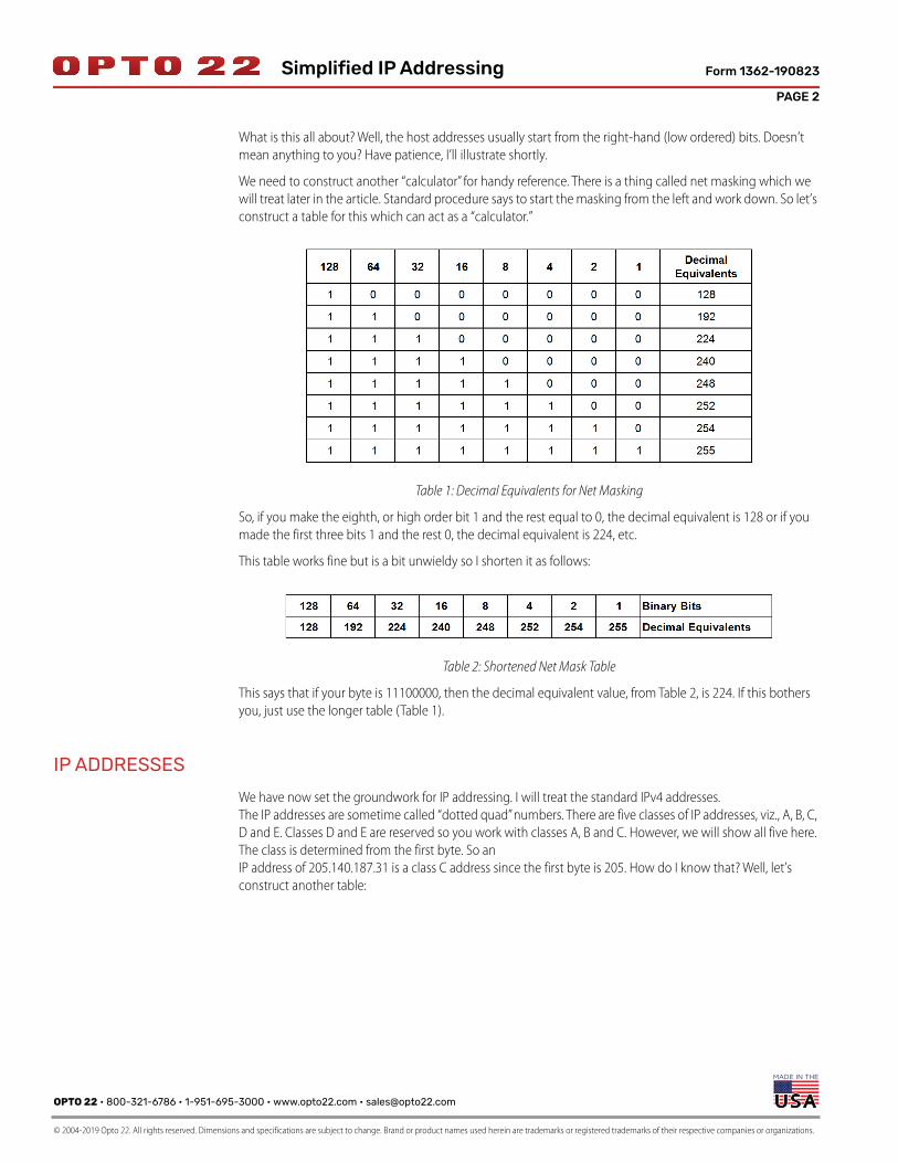
What is this all about? Well, the host addresses usually start from the right-hand (low ordered) bits. Doesn’t
mean anything to you? Have patience, I’ll illustrate shortly.
We need to construct another “calculator” for handy reference. There is a thing called net masking which we
will treat later in the article. Standard procedure says to start the masking from the left and work down. So let’s
construct a table for this which can act as a “calculator.”
Table 1: Decimal Equivalents for Net Masking
So, if you make the eighth, or high order bit 1 and the rest equal to 0, the decimal equivalent is 128 or if you
made the first three bits 1 and the rest 0, the decimal equivalent is 224, etc.
This table works fine but is a bit unwieldy so I shorten it as follows:
Table 2: Shortened Net Mask Table
This says that if your byte is 11100000, then the decimal equivalent value, from Table 2, is 224. If this bothers
you, just use the longer table (Table 1).
IP ADDRESSES
We have now set the groundwork for IP addressing. I will treat the standard IPv4 addresses.
The IP addresses are sometime called “dotted quad” numbers. There are five classes of IP addresses, viz., A, B, C,
D and E. Classes D and E are reserved so you work with classes A, B and C. However, we will show all five here.
The class is determined from the first byte. So an
IP address of 205.140.187.31 is a class C address since the first byte is 205. How do I know that? Well, let’s
construct another table:

OPTO 22 • 800-321-6786 • 1-951-695-3000 • www.opto22.com • [email protected]
© 2004-2019 Opto 22. All rights reserved. Dimensions and specifications are subject to change. Brand or product names used herein are trademarks or registered trademarks of their respective companies or organizations.
PAGE 3
Form 1362-190823Simplified IP Addressing
High Ordered Byte
Table 3: Classes of IP Addresses
How did I get table 3? I didn’t have to remember the whole thing, only a couple of pieces of information. Then
I constructed the rest. Let’s show how I did it. I knew that there are five classes of IP addresses and that the first
byte of the IP address tells you what class it is in. I also knew the schema for the binary starting value of the
first byte, i.e., 0, 10, 110, etc. Because of the way it follows a schema, the second column is easy to construct.
Now, using Table 2, it was easy to construct the third column.
Next, note that the fourth column (ending point) follows naturally by simply subtracting one from the
beginning of the next class. Let’s illustrate. A class C begins at 192 while a class D begins at 224. Hence a class
C must end at 223. Now you have no excuses about forgetting the beginning and ending points of each class;
merely remember the binary schema and take a minute to construct the table. On a side note, you don’t have
to worry about Classes D and E except the beginning of Class D tells you where Class C ends (subtract 1).
BITWISE AND
We need to discuss net-masking but, before doing it, let’s digress a moment and be sure everyone is up with
us. A Boolean AND is just like it is in English. You tell Johnny that you will buy him an ice cream cone if he puts
out the trash AND makes his bed. If he does neither or only one of them, he doesn’t get an ice cream cone (I
hope). But, if he does both, he gets the cone.
Bitwise AND’s work bit by bit. So, if you AND a 1 with a 1, you get a 1.
If you AND two 0’s, a 1 and a 0, a 0 and a 1, however, you get a 0.
Table 4 illustrates the operation.
Table 4: Bit-Wise Logical AND Truth Table

PAGE 4
OPTO 22 • 800-321-6786 • 1-951-695-3000 • www.opto22.com • [email protected]
© 2004-2019 Opto 22. All rights reserved. Dimensions and specifications are subject to change. Brand or product names used herein are trademarks or registered trademarks of their respective companies or organizations.
Form 1362-190823Simplified IP Addressing
Now let’s take a whole byte and do a Logical AND with another byte. Suppose the first byte is 10110010 and
the second byte is 01100111. Working from the right, note that the first byte has a decimal value of,
1*128 + 0*64 + 1*32 + 1*16 + 0*8 + 0*4 + 1*2 + 0*1 = 178,
while the second byte has a decimal value of,
0*128 + 1*64 + 1*32 + 0*16 + 0*8 + 1*4 + 1*2 +1*1 = 103.
Okay, we’re ready to do the AND’ing.
Table 5: Bit-Wise AND’ing
Let’s do one more. Let’s AND the 178 with 255.
Table 6: Bit-Wise AND’ing with 255 decimal
Not very interesting you say? But we need this fact for other work. We know, then, that when you bit-wise
AND any byte(number) with 255 you get the number dropping through,i.e., the result is merely the number
again. Now we are ready to start the net-masking, so here goes.
NET-MASKING
The default net-masks for the various classes are shown in Table 6 with some sample host IP addresses. Simply
put, a host is anything that has an IP address. This includes servers, workstations, routers, etc.
Table 7: Default Net-Masks, etc.
So, what does this mean and what do we do with it? Let’s work through the table. If we take the sample Class
A address, 10.0.1.23 and bitwise AND it with it’s default net-mask we obtain 10.0.0.0 Remember that AND’ing
a number (byte) with 255 merely gives the number again so the 255 AND’ed with 10 gives 10. Also 0 AND’ed
with anything, gives 0. So AND’ing 10.0.1.23 with 255.0.0.0 gives 10.0.0.0. What is 10.0.0.0? Why it’s the
network address. Look at the last column. Notice that the first byte gives the network address when AND’ing a
Class A network with it’s default net-mask. While the first two bytes give the network address when AND’ing a
Class B IP address with the default Class B net-mask.

OPTO 22 • 800-321-6786 • 1-951-695-3000 • www.opto22.com • [email protected]
© 2004-2019 Opto 22. All rights reserved. Dimensions and specifications are subject to change. Brand or product names used herein are trademarks or registered trademarks of their respective companies or organizations.
PAGE 5
Form 1362-190823Simplified IP Addressing
Hence we say that the first byte of a Class A IP address gives the network address and the three remaining
bytes give the host addresses, i.e., a Class A address has the form N.H.H.H, where N stands for Network and H
stands for Host. Likewise, the first two bytes of a Class B IP address pertain to the network and the last two
bytes pertain to the host address, viz., N.N.H.H. Finally, the first three bytes of a Class C IP address pertain to the
network while the last byte pertains to the host, viz., N.N.N.H.
That was a bit tedious so let’s re-cap. We have now covered Classes of networks, default net-masking, IP
addresses of networks and what those odd dotted-quad numbers mean. That done, it’s now time to move on
to sub-netting.
SUB-NETTING
Let’s illustrate with a Class B IP address such as 142.168.25.100.
From Table 6 we know that the default net-mask for a Class B network is 255.255.0.0. Hence AND’ing the
default mask with the IP address yields the address of the network that particular host is on, i.e., 142.168.0.0.
So a host with an IP address of 142.168.25.100 finds itself on a network with an IP address of 142.168.0.0 if a
default Class B net-mask is used. Easy enough.
Now, if you are granted a full Class B suite of addresses with a network address of 142.168.0.0, what do you do
with them? Remember a Class B network has the form of N.N.H.H, i.e., the last two bytes can be used for
assigning host IP addresses. This yields a network with 216 - 2 host addresses. The -2 comes from the fact that
142.168.0.0 is the network address so it can’t be assigned to a host and the last address on the network,
142.168.255.255 is used for broadcasts so it, likewise, can’t be assigned to a host.
This would be a very big network (65534 host addresses), far too big to be practical. A very simple approach is
to “borrow” one byte’s worth of host addresses and assign them as network addresses. That would yield 28 =
256 networks with 254 hosts on each. Even here these are large networks. This process, borrowing host
addresses and using them for networks, is called sub-netting. We accomplish this by using a sub-net mask
(SNM). In this case we would use a sub-net mask of 255.255.255.0 (the default Class C net-mask). Hence we
have taken one Class B network and turned it into 256 Class C networks.
Remember that AND’ing 255 with a number just gives the number again. So if we AND 142.168.25.100 with
255.255.255.0 we get a network address of 142.168.25.0 with the first available host address of 142.168.25.1
and the last of 142.168.25.254 (remember that the last address, i.e., 142.168.25.255 is reserved for broadcasts).
Another way of doing this is to start with the network address, 142.168.25.0 in this case, turn all host bits into
1’s and you have the broadcast address. Here the last byte is used for host addresses so turning them to ones
gives 142.168.25.255. This type of broadcast is called a directed broadcast, meaning that it jumps routers while
a local broadcast (doesn’t jump routers) has the form 255.255.255.255 no matter what class of network is
involved.
Whew! That was a lot. If you’re not too stunned at this point, you may wonder if you can only sub-net on byte
boundaries or you may ask, “can I sub-net a Class C network?” The answers are “no” and “yes”, respectively, i.e.,
you can work in the middle of a byte. This, then, brings us to the next topic.
SUB-NETTING ON NON-BYTE BOUNDARIES
Let’s say you are granted a full Class C suite of addresses, e.g., 210.168.94.0 as your network address. You are
allowed to assign the host addresses (the last byte) as you please. If you use the default Class C net-mask of
255.255.255.0, c.f. Table 6, then you can assign host addresses of 210.168.94.1 through 210.168.94.254 on a
single network. That’s feasible of course but you may want break this up into multiple networks of, say 25
hosts each.

PAGE 6
OPTO 22 • 800-321-6786 • 1-951-695-3000 • www.opto22.com • [email protected]
© 2004-2019 Opto 22. All rights reserved. Dimensions and specifications are subject to change. Brand or product names used herein are trademarks or registered trademarks of their respective companies or organizations.
Form 1362-190823Simplified IP Addressing
Let’s do some mathematics. If we have 4 bits for hosts, will it be enough? 24-2 = 14; not enough. Okay, let’s use
5 bits for hosts: 25-2=30. Ah, 5 bits for hosts will work. But we have 8 bits in the last byte for hosts. So let’s
borrow three bits for sub-networks and we still have the requisite 5 bits for hosts. Great, but how many
sub-nets do we have? How about 23=8.
We have, then, 8 sub-networks with 30 host addresses on each. If you are doing the math you are probably
saying, “but 8x30 is only 240 addresses, what happened to the others?” Valid question! Oops, don’t get sore
but it’s time to construct another table. Note that each address will have the form of 210.168.94.<last byte>.
And the SNM (Sub-Net Mask) will have the form 255.255.255.<last byte>. Hence let’s just work with the last
byte.
From Table 2 (or Table 1) we see that the SNM will be 255.255.255.224. The 224 comes from the last byte
being 11100000. So what are the sub-nets? Table 8 shows them (last byte only).
Table 8: Sub-Networks For The Above Class C Network
(Shows the Last Byte)
So let’s detail several of these. Let’s take the smallest. The full sub-network address of the smallest is
210.168.94.0. The next one up is 210.168.94.32, and so on. Remember that with
3 bits to work with, we get 23=8 sub-nets and looking at table 8 you see them.
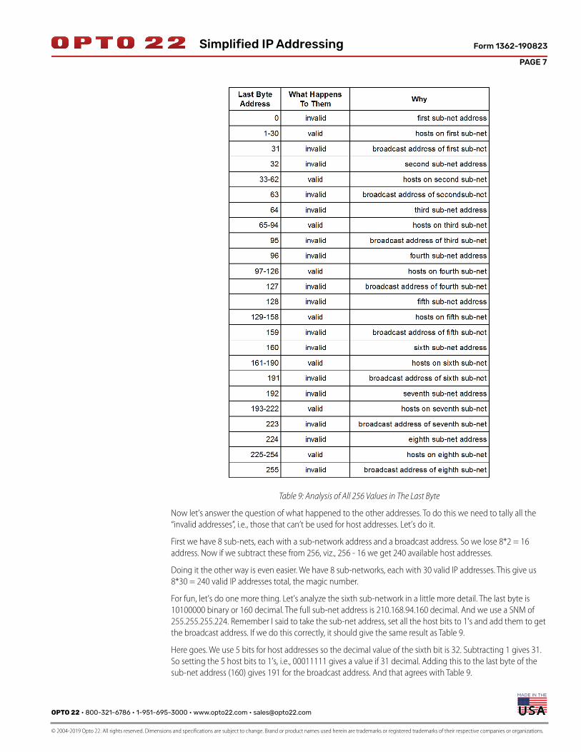
Back to the question of why we only get 240 host addresses. Gasp, you say, “not another table!” Sorry, but yes.
Looking at the last byte, we get:
OPTO 22 • 800-321-6786 • 1-951-695-3000 • www.opto22.com • [email protected]
© 2004-2019 Opto 22. All rights reserved. Dimensions and specifications are subject to change. Brand or product names used herein are trademarks or registered trademarks of their respective companies or organizations.
PAGE 7
Form 1362-190823Simplified IP Addressing
Table 9: Analysis of All 256 Values in The Last Byte
Now let’s answer the question of what happened to the other addresses. To do this we need to tally all the
“invalid addresses”, i.e., those that can’t be used for host addresses. Let’s do it.
First we have 8 sub-nets, each with a sub-network address and a broadcast address. So we lose 8*2 = 16
address. Now if we subtract these from 256, viz., 256 - 16 we get 240 available host addresses.
Doing it the other way is even easier. We have 8 sub-networks, each with 30 valid IP addresses. This give us
8*30 = 240 valid IP addresses total, the magic number.
For fun, let’s do one more thing. Let’s analyze the sixth sub-network in a little more detail. The last byte is
10100000 binary or 160 decimal. The full sub-net address is 210.168.94.160 decimal. And we use a SNM of
255.255.255.224. Remember I said to take the sub-net address, set all the host bits to 1’s and add them to get
the broadcast address. If we do this correctly, it should give the same result as Table 9.
Here goes. We use 5 bits for host addresses so the decimal value of the sixth bit is 32. Subtracting 1 gives 31.
So setting the 5 host bits to 1’s, i.e., 00011111 gives a value if 31 decimal. Adding this to the last byte of the
sub-net address (160) gives 191 for the broadcast address. And that agrees with Table 9.

PAGE 8
OPTO 22 • 800-321-6786 • 1-951-695-3000 • www.opto22.com • [email protected]
© 2004-2019 Opto 22. All rights reserved. Dimensions and specifications are subject to change. Brand or product names used herein are trademarks or registered trademarks of their respective companies or organizations.
Form 1362-190823Simplified IP Addressing
Table 10, below (sorry, another table) shows the “whole Magilla”:
Table 10: Analysis of The Sixth Sub-Network
One final point. Some authors use the term “sub-net mask” even when referring to the default net-masks.
They are just a tad loose with their terms. That ends my presentation. Happy IP addressing. And remember,
Linux is inevitable.
This article also appeared in Linux Journal, January 2000.
Prof Gene Hector, M.S., P.E. | Systems Integration
[email protected] | Caldera Business Partner

OPTO 22 • www.opto22.com SALES • [email protected] SUPPORT • [email protected] Business Park Dr. Temecula, CA 92590-3614 800-321-6786 • 1-951-695-3000 800-835-6786 • 1-951-695-3080
© 2001–2018 Opto 22. All rights reserved. Dimensions and specifications are subject to change. Brand or product names used herein are trademarks or registered trademarks of their respective companies or organizations.
More about Opto 22
Form 1335-181003
PRODUCTSOpto 22 develops and manufactures reliable, easy-to-use, open
standards-based hardware and software products.
Industrial automation, process control, building automation, industrial
refrigeration, remote monitoring, data acquisition, and industrial
internet of things (IIoT) applications worldwide all rely on Opto 22.
groov EPIC® System
Opto 22’s groov Edge Programmable Industrial Controller (EPIC)
system is the culmination of over 40 years of experience in designing
products for the automation industry.
groov EPIC gives you an industrially hardened system with
guaranteed-for-life I/O, a flexible Linux®-based controller with
gateway functions, and software for your IIoT application or any
application.
groov EPIC I/O
I/O provides the local connection to
sensors and equipment. groov I/O
offers up to 24 channels on each I/O
module, with a spring-clamp terminal
strip, integrated wireway, and swing-
away cover.
Opto 22 I/O is so reliable, we can afford
to guarantee it for life. groov I/O is hot
swappable, UL Hazardous Locations
approved, and ATEX compliant.
groov EPIC Controller
The heart of the system is the groov
EPIC controller. It handles a wide range of digital, analog, and serial
functions for data collection, remote monitoring, process control, and
discrete and hybrid manufacturing.
In addition, the EPIC provides secure data communications among
physical assets, control systems, software applications, online services,
and more, both on premises and in the cloud.
Configuring and troubleshooting I/O and networking is easier with
the EPIC’s integrated high-resolution touchscreen. Authorized users
can see your groov View HMI locally on the touchscreen or on a
monitor connected via the HDMI or USB ports.
groov EPIC Software
Software includes:
• Flowchart-based PAC Control for control programming, or build
your own custom application with optional secure shell access
• groov View for building and viewing your own device-
independent HMI
• Node-RED for creating simple logic flows from pre-built nodes
• Ignition Edge® from Inductive Automation®, with OPC-UA drivers
to Allen-Bradley®, Siemens®, and other control systems, and
MQTT/Sparkplug communications for efficient IIoT data transfer
groov Edge Appliance
Visualization, data handling, and connectivity in a
compact, industrial box: that’s the groov Edge
Appliance. Included are:
• groov View for building and viewing operator
interfaces on PCs and mobile
• Node-RED for building simple logic flows
• Ignition Edge from Inductive Automation, for
OPC-UA drivers and MQTT/Sparkplug IIoT communications
Older products
From solid state relays (our first products) to world-famous G4 and
SNAP I/O, to SNAP PAC controllers, Opto 22 products last a long time.
You can count on us to give you the reliability and service you expect.
QUALITYFounded in 1974, Opto 22 has established
a worldwide reputation for high-quality
products. All are made in the U.S.A. at our
manufacturing facility in Temecula,
California.
Because we test each product twice
before it leaves our factory rather than
testing a sample of each batch, we can
guarantee most solid-state relays and
optically isolated I/O modules for life.
FREE PRODUCT SUPPORTOpto 22’s California-based Product Support Group offers free,
comprehensive technical support for Opto 22 products from
engineers with decades of training and experience. Support is
available in English and Spanish by phone or email, Monday–Friday,
7 a.m. to 5 p.m. PST.
Support is always available on our website, including how-to videos,
user’s guides, the Opto 22 KnowledgeBase, troubleshooting tips, and
OptoForums. In addition, free hands-on training is available at our
Temecula, California headquarters, and you can register online.
PURCHASING OPTO 22 PRODUCTSOpto 22 products are sold directly and through a worldwide network
of distributors, partners, and system integrators. For more information,
contact Opto 22 headquarters at 800-321-6786 (toll-free in the U.S.
and Canada) or +1-951-695-3000, or visit our website at
www.opto22.com.