simplified design method of frame wall beam of composite …
TRANSCRIPT

11 th INTERNA TIONAL BRICKlBLOCK MASONRY CONFERENCE TONGJI UNIVERSITY, SHANGHAi, CHINA, 14 - 16 OCTOBER 1997
SIMPLIFIED DESIGN METHOD OF FRAME WALL BEAM OF COMPOSITE WALL BUILDINGS SUPPORTED ON FRAME
Zbang Qianguol Li Qioggangl Xue Hongweil Cbeo Degao2
Wu RuiduoJ Xi Xiaofeng3 Jie MingyuJ
I. ABSTRACT
The frame wall beam is a important bearing member. The quality of design is relate<! to safety and
economy of the buildings. Based on experimental study and theoretical analysis of the stress state of
frame wall beam, A simple, applicable, safe and economic design method is developed in this paper.
2. INTRODUCTION
The structure of composite wall supported on frame is the new structure system studied and
developed in 1990s, suitable for the commercial resident buildings wilh big space in lhe lower part
and small bay in lhe upper parto During eighth five years plan, The composite wall buildings of
million square meters were built in Shenyang only. It takes important ruIes in promoting economic
prosperity, convenience for lhe people, The great economic effect was obtained. The frame wall
beam is lhe beam of frame at lhe top of frame supported story in composite wall wilh framed ftrSt
story, il is a important member. 11 is used to be designed as flexural member or wall beam. The
methods determining lhe value of loads in the previous design melhods were lack of experimentai
and theoretical basis. The simplified calculation method in Chinese Code for Design of Masonry
S/rue/tires is not suitable for continuous waIl beam, still for wall without confined columns and
seismic region.
Keyword: Simplified Metbod; Frame Wan Beam; Composite Wan Supported 00 Frame.
1 Senior Engineer, Liaoning Institute of Architectural Design and Researcb
2Senior Engineer, Sbenyang Urban and Rtmll Construction Committee
3Senior Engineer, Department ofEngineering Mechanics, Dalian University Science and Engineering
523

Based on research on stress state of frame walI beam, a simple, applicable, economic and safe
design method is proposed in this paper.
3. MECHANICAL PROPERTIES
The frame wall beam is the beam of frame at the top of frame supported story in composite wall
with framed frrst story, being the joining part of two different structures, the position of the frame
walI beam is shown in Fig. l . The frame wall beam is different from nor the beam of frame or
common wall beam, The properties of the frame wall beam are as follows :
confined beam
Fig. l the position of frame walI beam
( 1 ) The reinforced concrete frame-shear wall structure is at the lower part of the frame wall
beam, the upper part is the reinforced concrete-brick composite wall structure;
(2) There are confined columns in wall above the frame walI beam, the confmed columns bear
forces together with masonry;
( 3 ) A part of vertical 10ad above the frame supportOO story is directIy passed to the columns of
the frame through confmed columns, the other·through interior arch effect of masonry,
reducing vertical forces on the frame waIl beam;
( 4) Under the vertical 10ad or both the vertical and horizontal load, the frame walI beam bears
bending, shear and axial forces.
524

4. EXPERIMENTS
Six 1/2 s, .tle frame supported composite wall panel models were tested, i,e., two transverse
composite wall models with frame supported fiest story ( with and without opening, as shoWII in
Fig.2 ) , two transverse composite wall models with frame supported flTst two story (with and
without opening, as shown in Fig,3 ) ,one longitudinal composite wall model with frame supported
flTSt story ( four bays with opening, as shoWII in Fig.4 ) , one longitudinal composite wall model
with frame supported flTSt two story ( four bays with opening, as shoWII in Fig.5 ) . On1y four
stories of the bottom of eight-story composite waIl with frame supported were selected for the above
wall panel models. But the models were used to simulate the behavior of the eight-story composite
wall with frame supported.
confined ..... ai top
Fig, 2 Transverse composite wall model
with frame supported first story
c:oofined ...... ai top
Fig. 3 Transverse composite wall model with
frame supported fiest two story
Fig. 4 Longitudinal composite wall model with frame supported flTSt story
525

. . .m _ ~75" _ ~ ~75 - ~ m- .'115. confined beam .1 Ih. lop t t _,. fi'-~ co!
:lIUecon U~ umn
11
Fig.5 Longitudinal composite wall model with frame supported flTSt two story
The experimental results showed:
( I ) The stress states of the transverse frame wall and longitudinal frame wall beam with no
opening or small-sized opening are similar to that of wall beam. The stress state of midspan
of the beam is eccentric compression, the stress state near the support is' eccentric tension,
mainly flexure. The arch effect of upper composite wall above the exterior longitudinal
frame wall beam with bigger opening is not significant. Its stress state is similar to tha! of
multi-span continuous beam.
(2) The load applied on the frame wall beam is distributed in shape of saddle. The load in the
support is great, the load in the midspan is small. There are loads varying along the axial of
the beam in the transverse frame wall beam, the stress in the midspan is tensile, the stress in
the support is compressive.
(3 ) Total loads passed from upper composite wall are mainly passed to the colmnn of fram.: by
confined colmnns and through the arch effect of composite wall above the beam of frame
wall, only a little part is passed to the colmnn of frame through the frame wall beam. As lhe
result, the frame wall beam does not bear great vertical load. Even if the beam is under
action ofhorizontal foroe, the beam bears less than 45% totalload, see Table I.
( 4 ) The beam of transverse frame wall out of the confmed colmnn, local vertical load in the
edge of opening increases a little.
T bl • e 1 t e proPOl o ve ca 081 me ramewa b rtion f rti " d bo b f llbea m
composite wall with frame composite wall with frame
Type ofwall panel suworted frrst story supported frrst two story
V V+ (1' ) V+ ( 80 ) V V+ (1' ) V+ ( 80 )
transverse with no openinll 23 .9 28 39 32.3 34.3 37.3
with opening 32.6 :3.5 37 30 35.7 41.5
ongitudinal Window opening 24.5 23.9 21.4 19.9
526
where
V - only vertical load
v+f - verticalload and horizontal force corresponding to earthquake of intensity Vil V +SO - verticalload and horizontal force corresponding to earthquake of intensity VI
5. NONLINEAR FINITE ELEMENT ANALYSIS
The composite wall with frame supported first (two) story of eight-slory building was ana\yzed by
plane nonlinear finite element method. The parameters used w the analysis are as follows:
• concrete strength grade:
C30 for columns of frame, C30 for beams of frame, e20 for confined column~ .
• opening in transverse composite wall:
no opening, opening in one side of middle column;
openings in two sides of middle column, openings in exterior side of mid-column in the side.
• opening in longitudinal composite wall
1500 X 1500, ISOO X 1500,
900 X 2000+1200 X 1500 ( door and window )
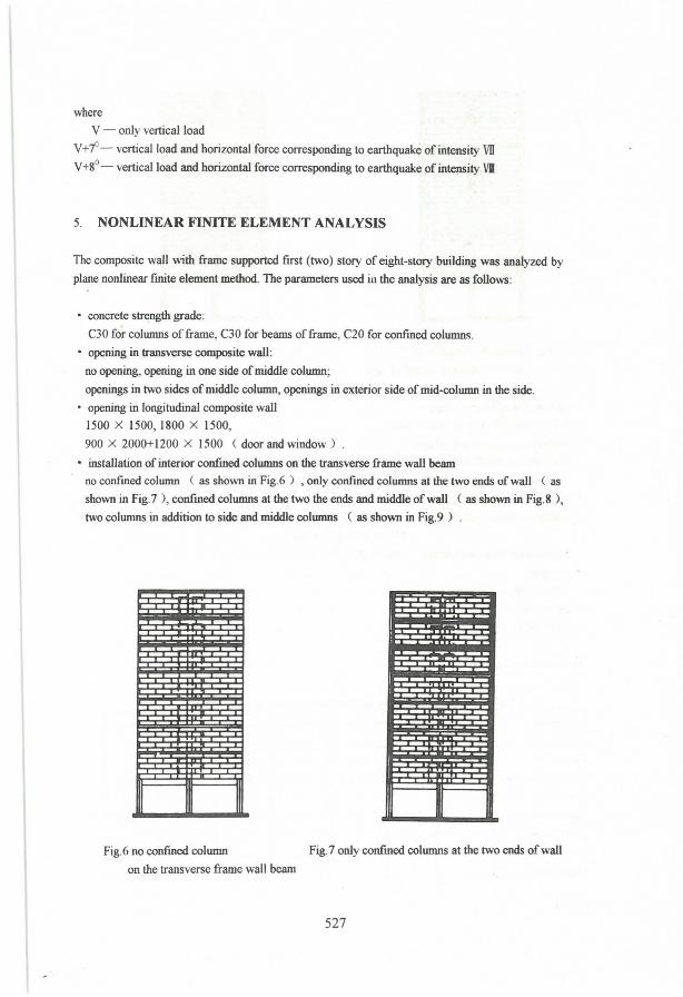
• installation of interior confmed columns on the transverse frame wall beam
no confmed column ( as shown in Fig.6 ) , only confmed columns aI the two ends ofwall ( as
shown in Fig.7 ), confined columns at the two the ends and middle ofwall (as sho\Vn in Fig.S ),
two columns in addition to side and middle columns (as shown in Fig.9 ) .
Fig.6 no confined column Fig.7 only confined columns at the two ends of wall
on the transverse frame wall beam
527
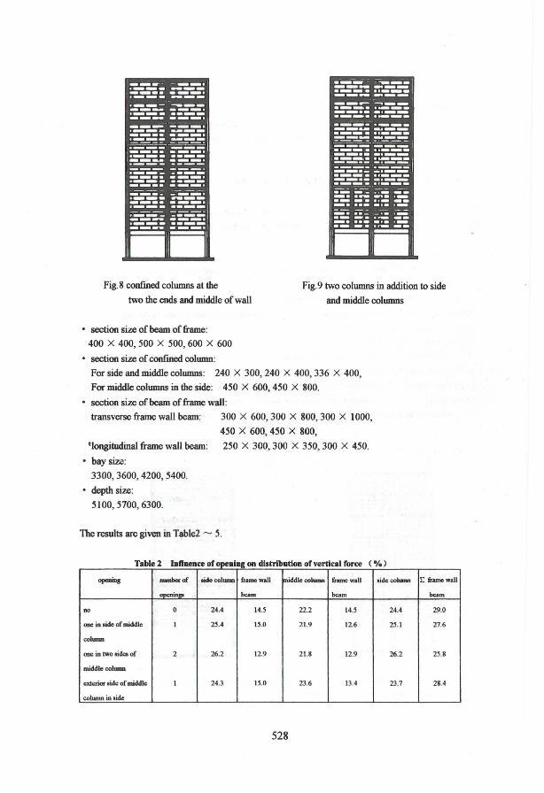
Fig.8 confined columns at the
two the ends and midd1e of wa11
Fig.9 two columns in addition to side
and middle columns
• section size of beam of frame:
400 X 400,500 X 500,600 X 600
• sectioo size of confmed column:
For side and midd1e columns: 240 X 300, 240 X 400, 336 X 400,
For midd1e columns in the side: 450 X 600, 450 X 800.
• section size ofbeam offrame wa1l:
transverse frame wall beam: 300 X 600,300 X 800,300 X 1000,
450 X 600,450 X 800,
tlongitudina1 frame wa11 beam: 250 X 300, 300 X 350, 300 X 450.
• baysiu: 3300,3600,4200,5400.
• depth size:
5100,5700,6300.
The results are given in Table2 - 5.
Table2 IIIn_ce of opeDIng on distrlbutíoD ofvertícal force (e/e)
opcnins numberof .idccolumn fmnc,.." middle column framcwaU .idccolumn
openinga bam beam
no O 24.4 14.5 22.2 14.5 24.4
ODe in .ide of middlc 1 25.4 15.0 21.9 12.6 25.1
column
one in MO .ides of 2 26.2 12.9 21.8 12.9 26.2
middle colunm
exterior .ide of middlc 1 24.3 15.0 23.6 13.4 23.7
column in .ide
528
E fmncwan
bam
29.0
27.6
25.8
28.4

T bl 3 D' 'b . f a e Istn ullon o vertic8 lfi orce when instaIIiDl! different confined column under vertical load
nwnber af scction size strength of sidecolwnn &ame waU middle frame waU sidccolwnn E frame
columns ofcolmnn masonry beam COIWM beam wall beam
3 400 X 240 MIO 25.0 13.3 23.4 13.3 25.0 26.6
5 300 X 240 MIO 24.6 17.3 16.2 17.3 24.6 34.6
5 400 X 240 MIO 24.4 14.5 22.2 14.5 24.4 29.0
5 400 X 240 M7.5 24.6 14.0 22.8 14.0 24.6 28.0
T able4 Influence of chall2e in size on distribution of vertical force
section size aide column + middle cohmm middle colunm in the side muomy
beam of frame stifIiIess ( % ) vcrt. force ( ~~ ) stilIn ... ( % ) vcrt. force ( % ) sti1Iitcoo ( % ) vcrt. force ( % )
400 X 400 49.7 67.9 23.6 10.1 26.7 22.0
500 x 500 49.7 67.1 23.6 10.5 26.7 22.4
600 x 600 49.7 66.5 23.6 10.7 26.7 22.8
T bl 5 8 e Influence o f chaDl!e in section of beam of frameand confined column on vertical force
Spec. No. section size of side colwnn+ mid. column beam in the side masonry verto Force
beam section size vert.fon:e(%l section sizc vert.forcei%\ vert.forcc(%) onbeam ( 0J0 )
SC I 0.45 X 0.6 0.336 X 0.4 71.69 0.24 X 0.4 7.27 21.04 28.3
SC2 0.45 X 0.8 0.336 X 0.4 67.1 0.24 X 0.4 10.45 22.45 32.9
SC4 0 .. 45 X 0.6 0.336 X 0.4 72.18 0.24 X 0.3 5.93 2l.S9 27.8
SC5 0.45 X 0.8 0.336 X 0.4 67.84 0.24 X 0.3 8.54 23.62 32.2
SC7 0.45 X 0.6 0.24 X 0.4 65.42 0.24 X 0.4 8.81 25.77 34.6
SC8 0.45 X 0.8 0.24 X 0.4 60.52 0.24 X 0.4 12.46 27.02 39.5
SC IO 0.45 X 0.6 0.24 X 0.4 65.93 0.24 X 0.3 7.21 26.86 34.1
SC U 0.45 X 0.8 0.24 X 0.4 61.28 0.24 X 0.3 10.22 28.50 38.7
The results of calculation and analysis showed:
( I ) The oumber of confined columns in upper wall has relatively great influeoce 00 the stress
state of the frame wall beam. The vertical load passed to the frame wall beam through the
wall without confmed colunm, is 69"10 total vertical load. Wheo the confmed columns are
installed at two eods of wall, the vertical load on the frame wall beam is 36% total load.
When confined colunms are instaIled at two ends and middle of wall, the vertical load on
the frame wall beam decreases to 36% totalload. When confined colunms are installed not
only at the two ends and middle of wall but a1so at the mid-span, the vertical load 00 the
frame wall beam is slightly higher than one for three confined columns.
( 2 ) The proportion of vertical load borne by the frame wall beam increases with stiffness of the
frame wall beam, decr~ases with increasing of openings in upper wall.
( 3 ) The change in section size of colunm of frame has little influence on the proportion of
vertical load borne by the frame wall beam.
( 4) The proportion of vertical load borne by the frame wall beam under earthquake of intensity
VII, vm is the same as that under only the vertical load.
529

6. SIMPLIFICA TION OF INTER:"lAL FORCE CALCULA TION FOR THE FRAME WALL BEAM
Under the action of verticalload or vertical anct horizontal 10acI, there are moments, shear and axial
forces in section of beam of frame wall (see Fig.6 and Fig.lO ) . where the moments and shear
forces are produced by vertical load applied on the frame wall oeaJtl. Though the vertical load is
distributed in shape of saddle the internai fvrce is the same as that in common beam with positive
moment at midspan and relatively small shear force, with negative moment at support and relatively
big sbear force. The axial force is produced by arch effect of wall, being tensile a! midspan and
compressive at support. Obviously, the beam is under eccentric compression in support, eccentric
tension at midspan. Wben designing project, the internal force computation and lhe verification of
section bearing capacity are rather complex and difficult if fmite element method is no! USf"d. For
sake of requirements, simplification is as follows:
2550 2550
Fig.lO Intemal,force in frame wall beam under the load
( I ) The results of fmite element analysis indicated that moments and axial forces produce
normal stress on the section of frame wall beam. The stress produced by axial forces is
about 15% that by moments. The moment is control internai force of section capacity of the
frame wall beiim. The reinforcement can be determined by appropriately increasin;
maximum design value of moment to meet requirements for the simultaneous action of
additional axial force. So it is necessary to calculate neither axial force nor reinforcement
byeccentric tensile or compressive member.
TabJe 6 Tbe internaI force in section of the beam of frame 1\'all under different Joads
~ bc:r I 2 3 4 5 6 7
internai foo:c ~ ~crtical, shear force -\84.5 -32.2 51.7 92.2 76.4 32.2 -61.0
~ action of shear fo rcc -185.3 -32.5 51.8 92.6 77.2 33.2 -59.5
Ivertica~ shear fon:e -1~1.8 -41.2 54.3 107.4 84.4 26.7 -60.7
Momenl WcniDR -188.9 -4\.9 6\.2 99.0 78.6 32.4 -62.2
530

M ( kN' M ) Ivertical f"",e Dlw I I_li -242.1 ~0.6 36.8 82.7 85.4 79.0 50.6
1z00KN horiz. f"",e I rioht -115.6 -2.29 61.1 88.1 60.9 -14.6 -168.2
~O% total vertical f= -311.1 ~9. 5 88.8 163. 8 155 .4 63.7 -111.3
~O% totalload plw I I_li -281.1 -91.0 44.2 123.9 147.9 116.5 29.4
1200KN horiz. f= I rioht -135.5 -3.5 73.1 94.0 59.4 -30.7 -176.4
tvertical. shcar force 221.1 122.4 74.8 6.5 -32.4 ~5.5 -121.3
~o action of shear fo rce 221.4 122.9 75.3 6.7 -31.9 ~5 . 1 -121.1
Iv ert.ica~ shcar f= 216.5 129.2 92.3 18.4 -46.7 -80.6 -57.0
Shear force IoPening 225.9 162.6 90.8 5.9 -36.9 ~8.8 -124.3
Q ( KN ) Ivertical f"",e plus I left -267.8 -145.6 -90.8 2.4 0.7 16.6 44.1
I:iOOKN horiz. f=e I rioht 176.5 91.8 50.8 14.8 -59.5 -110.2 -195.9
0% total vertical force 334.5 235.3 137.2 39.2 -58.9 -156.9 -254(~_
~O% totalload plus I left -257.0 -191.6 -126.3 ~O.9 4.41 69.8 135.2
tzOOKN horiz. f"",_ I rioht 188.0 122.6 57.3 -81.0 -73.5 -138.8 -204.2
Ncrtical. shear force -5.6 33 .2 63.8 \36.6 80.4 53.3 ~.3
o action of shC3f fo ece -29.1 -29.1 -29.1 -29.1 -29.1 -29.1 -29.1
tvertical, shear force -39.2 39.5 57.0 127.6 67.6 49.9 ~.23
A:u.lf=e bDCnin. -14.6 47.2 75.1 143.7 84.9 56.4 ~.O
N ( K'J ) Ivertical f"",o plw I 1011 -46.6 ~.2 35.5 129.4 110.5 101.5 85 .1
Izoo~ horiz. force I rioht 34.4 66.1 87.3 145.1 48.5 3.3 -45.3
160% total vertical f= -42.6 -42.6 -42.6 -42.6 -42.6 -42.6 -42.6
~O% totalload pios I left -33.6 -33.6 -33.6 -33.6 -33.6 -33.6 -33.6
bOOKN horiz. f"",e I rioht -22.6 -22.6 -22.6 -22.6 -22.6 -22.6 :~
Note: I , The example is an actual project, which has a frame shear wall in fust story and are reinforced
concrete composite wall in upper seven stories.
2, The bay ofthe project is 3.3Om, the depth is 5. 10m.
( 2 ) The loads distributed in shape of saddle on the frarne wall beam are converted into
uniform.Iy distributed load by tlu: principie of maximum moment equivalenl. It is easy to
calculate the internai forces ( moment, shear force) by unifonnly distributed load.
( 3 ) Under only vertical force, the shear force applied at the top of the frarne wall beam can be
equilibrium itself. The shear force which has little influence on the moment can be ignored.
( 4 ) The constructional requirements was mel.
7. THE APPROXIMA TE CALCULA TING METHOD
As discussed in part 6, the ·internal force and bearing capacity of the section can be calculated by
uniform.Iy distributed 'oad applied on the frame wall beam. It is the key to determine the wliformly
distributed load reasonably. Based on the nonJinear fmite element analysis and comparison analysis,
the appr'Jximate caIculating method was proposed.
( I ) According to following Eq. ( 7.1.1 ) , the uniformly distributed verticalload applied on the
transverse frame wall beam is approximately computed !IS
531

where
qf - uniformly distributed verticalload applied on the transverse frame wall beam,
EIAI - the sum ofaxial compressive stiffness of side and middle columns,
L EiAi - total axial compressive stiffness of composite wall,
EJc- the bending stiffness ofthe frame wall beam (Ec in Mpa, Jc in m4) ,
QH - the sum of verticalloads above the beam of transverse frame wall,
L: - the net span of the beam of transverse frame wall,
( 7.1.1 )
The above formula is also suitable for the interior and exterior longitudinal frame wall beam with
openings less than 1000mm.
(2) According to following Eq. ( 7.2.1 ) , the uniformly distributed verticalload applied on the
longitudinal frame wall beam is approximately computed as:
Z ( EcAc QZ qL = 1.2 0.5 - 0.387 "" ). / Lo L."EA
where
qZ - uniformly distributed load applied the longitudinal frame wall beam,
EcAc - the sum of compressive stiffness of confmed columns,
L EiAi - the sum of compressive stiffness of masonry and confmed columns,
QZ - the sum ofverticalloads above the longitudinal frame wall bearn,
L~ - the net span of longitudinal frame wall beam.
8. SIMPLIFIED CALCULATION OF THE FRAME WALL BEAM
( I ) to calculate the sum of verticalloads above the frame wall beam;
( 7.2.1 )
(2) to calculate uniformly vertical load borne by the transverse and longitudinal frame wall beam by Eq. ( 7.1.1) and ( 7.2.1), respectively.
(3 ) to calculate the internai forces (M, V) of the transverse and longitudinal frame wall
beam by the method used for continuous beam;
( 4) to check bearing capacity of cross section as flexural member;
( 5 ) the frame wall beam shall comply with the following constructional requirements:
• The longitudinal tension or compression reinforcement of the beam should not have joints. If any,
Weldedjoint should be used, and the area ofreinforcement injoint should be not less than 25%
the area of total reinforcements in the same section;
• Not less than 50% the upper negative moment reinforcements should be extended over the full
length of the beam. The lower positive moment reinforcements should be extended to the column
and anchored with the column;
• Thc waist reinforcement should be installed along the height of the beam. The waist
reinforcements in the longitudinal frame wall beam should not be less than 2 <I> 12, ones in the
transverse frame wall beam should not be less than 2 <I> 14, the spacing not more than 25Omm;
532

• The main and waist reinforcements should be;; anehored as tension reinforcements;
• The diameter of stirrups in the frame wall beam should be less than 8mm, the spaeing not more
than200mm;
• The spaeing of the stirrups in the region of 1.5 times beam height at the cnd of the beam and in
the region of the door openings of the transverse frame wall beam and 500mm far from the edge
of opening should be less than 10Omm;
• Not less than 2 <I> 16 ceiling reinforcements should be installed in the mid-column at the side of
transverse frame wall beam.
9. CONCLUSIONS
( I ) The frame wall beam is the beam of frame at the top of frame supported story in composite
wall with framed flrSt story, being the joining part of two different structures, it is a key
bearing member in sueh struetures. Based on the experimental study and theoretieal
analysis, the approximate calculation formula for design of the frame wall beam, simplified
ealeulation method and seismie construetional measures are proposed.
(2 ) It is not oniy safe and reliable to use the methods presented in this paper for design of the
frame wall beam, but also eapable of saving the main materiais, in designing a same beam
of frame wall, about 28.6% conerete ean be saved, longitudinal reinforcements 23 .8%,
stirrup 48.9%.
(3 ) Design methods proposed in this paper ean still be extended to design of the beam
analogous to the frame wall beam.
REFERENCES
I, R. H. Wood, Studies in composite construetion, Part I , The composite aetion of briek panel
walls supported on reinforced conerete beam, HMSO, London, 1952, National Building Studies,
Researeh Paper 13.
2, British Standards lnstitution, Struetural Recommendation for Load-bearing Walls, BSI, London,
1970, CPllI (Replaced by BS5628 Part 1 and 2).
3, Stress State of Frame Wall Beam of Composite Wall Supported on Frame at First Story,
Ruifang Wu, etc., Published in this Proceedings.
533