simplified analysis of an automatic transmission torque ... · simplified analysis of an automatic...
TRANSCRIPT
Fluid Mechanics 24-231
April 27th, 2012, Pittsburgh, PA 1
Simplified Analysis of an Automatic Transmission Torque Converter
Christy St-John, Emerson Silva, Eleanora Allen, Si Hoon Kwon, and Nikhil Roy
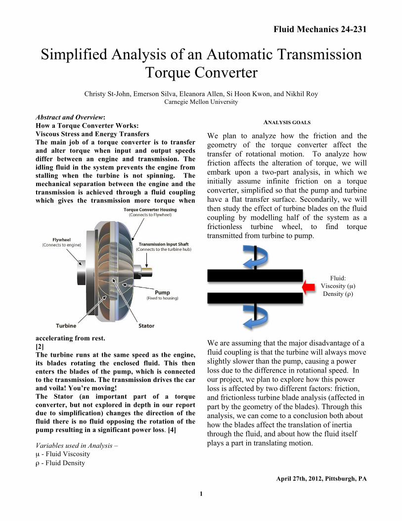
Carnegie Mellon University Abstract and Overview: How a Torque Converter Works: Viscous Stress and Energy Transfers The main job of a torque converter is to transfer and alter torque when input and output speeds differ between an engine and transmission. The idling fluid in the system prevents the engine from stalling when the turbine is not spinning. The mechanical separation between the engine and the transmission is achieved through a fluid coupling which gives the transmission more torque when
accelerating from rest. [2] The turbine runs at the same speed as the engine, its blades rotating the enclosed fluid. This then enters the blades of the pump, which is connected to the transmission. The transmission drives the car and voila! You’re moving! The Stator (an important part of a torque converter, but not explored in depth in our report due to simplification) changes the direction of the fluid there is no fluid opposing the rotation of the pump resulting in a significant power loss. [4] Variables used in Analysis – µ - Fluid Viscosity ρ - Fluid Density
ANALYSIS GOALS
We plan to analyze how the friction and the geometry of the torque converter affect the transfer of rotational motion. To analyze how friction affects the alteration of torque, we will embark upon a two-part analysis, in which we initially assume infinite friction on a torque converter, simplified so that the pump and turbine have a flat transfer surface. Secondarily, we will then study the effect of turbine blades on the fluid coupling by modelling half of the system as a frictionless turbine wheel, to find torque transmitted from turbine to pump.
We are assuming that the major disadvantage of a fluid coupling is that the turbine will always move slightly slower than the pump, causing a power loss due to the difference in rotational speed. In our project, we plan to explore how this power loss is affected by two different factors: friction, and frictionless turbine blade analysis (affected in part by the geometry of the blades). Through this analysis, we can come to a conclusion both about how the blades affect the translation of inertia through the fluid, and about how the fluid itself plays a part in translating motion.
Fluid: Viscosity (µ) Density (ρ)

Fluid Mechanics 24-231
April 27th, 2012, Pittsburgh, PA 2
FLUID MECHANICS ANALYSIS
Part 1: Torque Converter with Infinite Friction and No Blades
Velocity Profile:
€
δuδz
=(ω in −ω out )r
h
€
τ = µδuδz
= µ(ω in −ω out )r
h
€
M = rτδA = rµ (ω in −ω out )rh
2πrδr0
R
∫∫
€
M =πD4µ(ω in −ω out )
32h
Then, solving for Wout:
€
ω out =ω in −32MhπD4µ
Summary: By varying µ, one easily altered variable in our resulting relation, we can see simple relationships emerging between µ and Wout, as shown in Graph 1 to the right. This viscosity relationship helps show how the effects of the friction forces in this analysis work in tandem with blades to transfer additional energy to the torque converter’s pump. The graph (relating viscosity and output rotational speed) assumed a 12-inch diameter torque converter with input speed 100 radians per second. We estimated a real-world distance between the pump and the turbine as being 1 inch and determined the torque as 3.6745*103 lb*in (which we got by estimating 50% efficiency).
Through this analysis we realize that the viscosity greatly increases the transfer of torque through the system. Were we concerned solely with rotational transfer, the optimal viscosity would be as high as possible. However, in a real torque converter, we also need to consider that the pump and turbine must sometimes spin at different speeds when a car is stopped so as not to damage the engine. Thus, the ideal fluid would have a viscosity high enough to transfer a significant torque, but not so high as to retain excessive amounts of heat if the driving shaft were to stall.
Fluid Mechanics 24-231
April 27th, 2012, Pittsburgh, PA 3
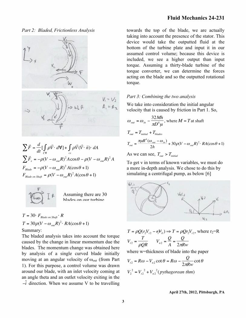
Part 2: Bladed, Frictionless Analysis
€
F = d
dt[ ρ
V
C∀∫∑ ⋅ d∀]+ ρ
V (
V ⋅ n )⋅ dAcs∫
€
F x = −ρ(V −ω outR)
2∑ Acosθ − ρ(V −ω outR)2A
€
FBlade = −ρ(V −ω outR)2A(cosθ +1)
€
FBlade on Shaft = ρ(V −ω outR)2A(cosθ +1)
€
T = 30⋅ FBlade on Shaft ⋅ R
€
T = 30ρ(V −ω outR)2 ⋅ RA(cosθ +1)
Summary: The bladed analysis takes into account the torque caused by the change in linear momentum due the blades. The momentum change was obtained here by analysis of a single curved blade initially moving at an angular velocity of ωout (from Part 1). For this purpose, a control volume was drawn around our blade, with an inlet velocity coming at an angle theta and an outlet velocity exiting in the
€
−ˆ i direction. When we assume V to be travelling
towards the top of the blade, we are actually taking into account the presence of the stator. This device would take the outputted fluid at the bottom of the turbine plate and input it in our assumed control volume; because this device is included, we see a higher output than input torque. Assuming a thirty-blade turbine of the torque converter, we can determine the forces acting on the blade and so the outputted rotational torque.
Part 3: Combining the two analysis We take into consideration the initial angular velocity that is caused by friction in Part 1. So,
€
ω out =ω in −32MhπD4µ
, where
€
M = T at shaft
€
Tout = Tinitial +Tblades
€
Tout =πµR4 (ω out −ω in )
2h+ 30ρ(V −ω outR)
2 ⋅ RA(cosθ +1)
As we can see,
€
Tout > Tinitial
To get v in terms of known variables, we must do a more in-depth analysis. We chose to do this by simulating a centrifugal pump, as below [6]
€
T = ρQ(r2Vt 2 − r 1V t1)⇒ T = ρQr2Vt 2 , where r2=R
€
Vt2 =T
ρQR
€
Vn2 =QA
=Q
2πRw
where w=thickness of blade into the paper
€
Vt2 = Rω −Vn2 cotθ = Rω −Q
2πRwcotθ
€
V22 =Vt2
2 +Vn22(pythagorean thm)
Assuming there are 30 blades on our turbine

Fluid Mechanics 24-231
April 27th, 2012, Pittsburgh, PA 4
€
V = ( Q2πRw
)2 + (Rω −Q
2πRwcotθ )2
€
V =Q2
(2πRw)2+ R2ω 2 −
QcotθπRw
+Q2 cot2θ(2πRw)2
€
V =Q2
(2πRw)2(1+ cot2θ ) + R2ω 2 −
QcotθπRw
In this analysis, take Q to be the amount of liquid flowing into one side of the torque converter from the other. This is not a completely accurate representation, because we assume Q to be flowing strictly axially between plates, and varying only with how much liquid is initially inputted into the converter. Final Tout equation:
€
Tout =πµR4 (ω out −ω in )
2h+
30ρ( Q2
(2πRw)2(1+ cot 2θ) + R2ω 2 −
QcotθπRw
−ω outR)2
⋅RA(cosθ +1)
Part 4: Analysis Conclusion The intuitive expectations going into this analysis were cracked wide open as we came out of it. Initially, we planned to gain insight into the efficiency of a torque converter in comparison to its mechanical counterparts: say, a clutch or VFD. This supposed efficiency would be in terms of the output versus input angular velocity or output versus input torque, and would hopefully show a meaningful discrepancy in which aspect of a torque converter contributed the most to its function. What we instead discovered was an output torque multiplication factor through the whole system, which, though it goes against the simpler model we had initially considered (with no stator), follows with the expectation of real-world data, where fluid gear reduction such as we see in torque converter acts on a scale from a 1.8:1 to a 5.0:1 gear reduction. [5]
Some small side notes: -With the simplifications we made, we can only intuit how surface friction plays a role when our fluid is moving along the blades of the turbine, perpendicular to radial movement. However, even assuming that they detract from outputted fluid velocity and so output torque, the torque outputted to the wheels is higher than the input torque. -Retrospectively, if we had a better understanding of the details of this system in the beginning, we could have better analyzed where the loss in energy goes; from friction, overheating, and slip.
GLOBAL, ENVIRONMENTAL, AND SOCIO-ECONOMIC IMPACTS
Automatic transmissions first came on to the scene in the late 1930s, the torque converter replacing the mechanical clutch. [5] While both devices separated the engine and transmission with the purposes of transferring different configurations of geared torque to the drivetrain of the car, the fluid coupling of the torque converter acts as a low maintenance surrogate for the more easily worn out parts of a clutch. Although a torque converter is not 100% efficient due to loss in energy from heat, it has numerous beneficial aspects that make it globally and environmentally friendlier than a clutch.
1. When exposed to the wear and tear in an average work environment, the flexible casing and fluid’s ability to absorb impact allow for little to no wear in the system over prolonged use. The lack of fatigue leads to fewer replacement parts, and a very long life for any torque converter.
2. Torque converters are used in a wide variety of machines, ranging from conveyor belts to commercial automobiles. With a more widespread usage of fluid couplings, part replacement necessity could be reduced by a factor of three or more! (In the automobile industry, converters should only need to be replaced

Fluid Mechanics 24-231
April 27th, 2012, Pittsburgh, PA 5
after 18-20 years of use. The common clutch needs replacement after about five.)
The difficulty of analysis that goes into considering the various aspects that affect real-world fluid couplings can be understood in this simpler analysis. Even though vast simplifications were made on all fronts, the analysis was still complex. While fluid couplings are very useful low-wear, low-replacement rate devices, their technical obscurity and difficulty of analysis make more commonplace and environmentally unfriendly surrogates the more popular choice. For the sake of reducing environmental waste, it would be optimal for systems reliant on fluidic energy transmission to become more prominent in the future.
REFERENCES
[1] “Fluid Coupling.” Wikipedia. Retrieved 23 April 2012. <http://en.wikipedia.org/wiki/Fluid_coupling>
[2] Google PDF <http://www.google.com/url?sa=t&rct=j&q=&esrc=s&source=web&cd=2&ved=0CDsQFjAB&url=http%3A%2F%2Fwww.autoshop101.com%2Fforms%2FAT02.pdf&ei=KqaYT5TaKKLa0QHx4silCg&usg=AFQjCNFVcI_xezqezIehsE2oEC4H3jX8gA>
[3] Kano, Shinya et al. “Prediction of Torque Converter Characteristics by Fluid Flow Simulation”. Komatsu Technical Papers 50 (2004): 1-6. Print.
[4] Nice, Karim. “How Torque Converters Work.” How Stuff Works. Retrieved 23 April 2012. <http://auto.howstuffworks.com/auto-parts/towing/towing-capacity/information/torque-converter.htm>
[5] “Torque Converters.” Wikipedia. Retrieved 21 April 2012. <http://en.wikipedia.org/wiki/Torque_converter#Efficiency_and_torque_multiplication>
[6] White, Frank M. Fluid Mechanics. 4th ed. Boston: McGraw Hill, ND. Print.