simple machines. investigation 1 simple machines
TRANSCRIPT

SIMPL
E MACHIN
ES

INVESTI
GATIO
N 1
SI M
PL E
MA
CH
I NE
S

SIMPLE MACHINES
There are 6 different types of simple machines Pulley Lever Inclined Plain Screw Wedge Wheel and Axle

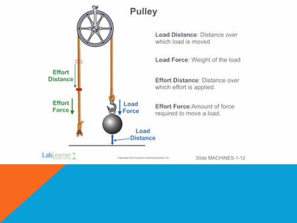
THE PULLEY
A pulley consists of a small wheel with a groove that a rope or string can slide over.
It is used to lift heavy objects

THE PULLEY
The load force is essentially the weight of the object to be lifted.
It is measured in newtons (N) the following simple formula to calculate load force:

WORK
Work takes into account the properties of force and distance.

MECHANICAL ADVANTAGE
Work may seem easier with simple machines, but they do not decrease the amount of work

PULLEY MECHANICAL ADVANTAGE

MECHANICAL ADVANTAGE
Mechanical Advantage describes the relationship between effort force and force of gravity on the load (load force)
Mechanical Advantage = Load Force Effort Force
It may seem easier if the MA is greater than 1, but a MA greater than 1 occurs if the machine allows the user to exert less force to move the same amount of load than if a machine was not used

HOW CAN SIMPLE MACHINES CHANGE THE FORCE NEEDED TO LIFT A LOAD?
Simple machines can change the force needed to lift a load by offering a mechanical advantage. In a one pulley system, the effort force required to lift the load is identical to the load force. Thus, there is no mechanical advantage in a one-pulley system.
However, in a two pulley system, the effort force is less than the load force. It takes roughly half the amount of force to lift the load. Thus, a two pulley system has a mechanical advantage of 2.
This is offset by the fact that in a two-pulley system the distance over which the effort is applied is greater than the distance over which the effort is applied in a single pulley system.

HOW DOES MECHANICAL ADVANTAGE RELATE TO EFFORT AND LOAD FORCES?
Mechanical advantage is the ratio of load force to effort force. If the load force is much greater than the effort force, then there will be a mechanical advantage.

INVESTI
GATIO
N 2 A
ND 3
SI M
PL E
MA
CH
I NE
S


LEVERS
There are 3 classes of levers all consist of three parts: Load Effort Fulcrum
The placement of these three parts changes the force needed to lift a load.


HOW CAN SIMPLE MACHINES CHANGE THE FORCE NEEDED TO LIFT A LOAD?
In a first and second class lever, as the length of the effort arm or load arm is changed, the distance over which the effort must be applied or the load must be lifted changes. Because the distance over which these forces are applied changes, the effort force also changes.
In a third class lever, as the length of the effort arm is changed, the distance over which the effort must be applied also changes. Because the distance over which this force is applied changes, the effort force also changes.

HOW DOES THE RELATIONSHIP BETWEEN THE FULCRUM, EFFORT AND LOAD AFFECT THE FORCE NEEDED TO LIFT A LOAD?
Changing the position of the fulcrum, effort, and load in relation to one another changes the distance over which a load is lifted and effort is applied.
The result is a change in the effort force depending upon the lengths of the effort and load arms and position of the fulcrum, load and effort.
When the fulcrum is between the load and effort, the effort force may equal the load force if the load and effort arms are equal. The effort force may be greater than the load force if the effort arm is shorter than the load arm. The effort force may be less than the load force if the effort arm is longer than the load arm.
As the fulcrum moves closer to the load, the effort arm becomes longer and the load arm shorter, and the effort force decreases below that of the load force. At some point, the fulcrum may move past the load, and the “first class lever” is now classified as a “second class lever.”

HOW DOES MECHANICAL ADVANTAGE RELATE TO EFFORT AND LOAD FORCES AND THE LENGTHS OF EFFORT AND LOAD ARMS?
Mechanical advantage is equal to 1 when the load and effort force are equal and the length of the load arm and effort arm are equal. As the effort force decreases below that of the load force, mechanical advantage becomes greater than 1.
As the effort force increases above that of the load force, mechanical advantage becomes less than 1. As the effort arm becomes longer than then the load arm, mechanical advantage becomes greater than 1. As the effort arm becomes shorter than the load arm, mechanical advantage becomes less than 1.

OTHER S
IMPL
E MACHIN
ES
SI M
PL E
MA
CH
I NE
S

• An inclined plain essentially creates a slope from one level to the next.

r is radius of shaft
l is the “lead” = the axial distance (parallel to shaft) the screw travels with one complete turn. In most types of screws, this is the distance between two consecutive threads.

• The mechanical advantage (MA) of a wheel and axle is simply the wheel diameter (Wd) divided by the axle diameter (Ad):
• Multiple levers working together around on fulcrum (axel)
• Distance that any point on the edge of the wheel (its circumference) travels can be much further than a point on the edge of the axle (it circumference).
• This is what provides the mechanical advantage when effort is applied to the wheel.

• Similar to an inclined plane in shape
• The important dimensions in terms of mechanical advantage with a wedge are its side length and its thickness.
• The side length is measured from the point of the wedge to the point where the tapering to the point begins.
• The longer a wedge’s side length compared to its thickness increases the mechanical advantage of a wedge.
• Thus, a long, sharp wedge will have more mechanical advantage that a short stubby wedge.
• A good way to appreciate the relationship between side length and width of a wedge is to imagine what happens as side length is shorted to a point where there is almost no point on the wedge at all.