simple evse wallbox - ev-power · simple evse wallbox can tell the vehicle to follow the actual pv...
TRANSCRIPT

Simple EVSE Wallboxdatasheet
Table of ContentsIntroduction.............................................................................................................................2
Read me first.................................................................................................................2Theory of operation.......................................................................................................2Compatibility..................................................................................................................2
Board description...................................................................................................................3Features.................................................................................................................................4
Current limitation – using PROG pin 5..........................................................................4Current boost – using PROG pin 4................................................................................4Precise current setting with Analog Input......................................................................5Current limitation based on external hall sensor (experimental)...................................5External LED..................................................................................................................5
Application examples.............................................................................................................6Minimal connection........................................................................................................632A EVSE with connector J1772...................................................................................7Customer solutions........................................................................................................8
New firmware flashing............................................................................................................9
Last document update: 26th May 2015
1

IntroductionEVSE stands for electric vehicle supply equipment. It is an element that supplies electric energy for the recharging of electric or plug-in vehicles.
Read me first
The EVSE board is supplied with default 32A settings. Please check the chapter Application examples for more information about further possibilities of changing maximumcharging current. 220 Ohm RPP is included with the kit (pre-hard-wired).
Theory of operation
Pilot signal duty cycle provided by EVSE defines maximum charging capacity. The car can define several states by pulling the pilot signal down to certain voltage levels (3V, 6V, 9V). Based on this feedback EVSE will trigger the relay for the vehicle to charge or evaluate thestate as an error (electricity will not be provided to the output socket/connector).
For more information please check:
• http://en.wikipedia.org/wiki/IEC_62196• http://en.wikipedia.org/wiki/SAE_J1772• https://github.com/kortas87/simple-evse/wiki (https://code.google.com/p/simple-evse/)
Resistance PP-PE (max cable throughput)Resistance [ohm] Current limit [A] Wire cross-section [mm2]
> 1500 * 6 --
1500 13 1.5
680 20 2.5
220 32 6
100 63 16
<100 ** 80 –* no resistor connected** recommended ~50 Ohm
Compatibility
• Tesla Model S• Nissan Leaf• Mitsubishi iMiev (Peugeon iOn, Citroen cZero)• Opel Ampera• eGolf• Mitsubishi Outlander PHEV• Citroen Berlingo Electrique• and others
2

Board descriptionSimple EVSE board has 2 connectors. 4-pin X1 for high voltage side and 6-pin for signaling wires and control. There is also PROG connector used for new firmware flashing (ICSP) and can be further used for adjusting EVSE current (see Features chapter).
X1 connectorpin name description
L phase 230V power supply for EVSE board and external contactorN neutral
PE protection-earth Ground reference
rel relay output This output drives coil of an external contactor. Maximum allowed current is 3A.
X2 connectorpin name description
AN analog input Used for button or current sensor input
LED external LED Includes 1k resistor onboard, connects to LED anode against ground
GND ground Ground reference
5V 5V power output Used as a power supply for external current sensor(max 40mA)
PP proximity pilot To vehicle connector
CP control pilot To vehicle connector
3
X1, X2 and PROG connector
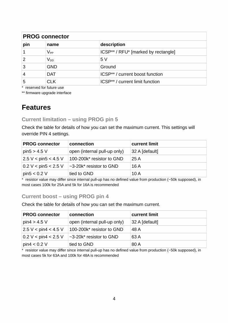
PROG connectorpin name description
1 VPP ICSP** / RFU* [marked by rectangle]
2 VDD 5 V
3 GND Ground
4 DAT ICSP** / current boost function
5 CLK ICSP** / current limit function* reserved for future use** firmware upgrade interface
Features
Current limitation – using PROG pin 5
Check the table for details of how you can set the maximum current. This settings will override PIN 4 settings.
PROG connector connection current limit
pin5 > 4.5 V open (internal pull-up only) 32 A [default]
2.5 V < pin5 < 4.5 V 100-200k* resistor to GND 25 A
0.2 V < pin5 < 2.5 V ~3-20k* resistor to GND 16 A
pin5 < 0.2 V tied to GND 10 A* resistor value may differ since internal pull-up has no defined value from production (~50k supposed), in most cases 100k for 25A and 5k for 16A is recommended
Current boost – using PROG pin 4
Check the table for details of how you can set the maximum current.
PROG connector connection current limit
pin4 > 4.5 V open (internal pull-up only) 32 A [default]
2.5 V < pin4 < 4.5 V 100-200k* resistor to GND 48 A
0.2 V < pin4 < 2.5 V ~3-20k* resistor to GND 63 A
pin4 < 0.2 V tied to GND 80 A* resistor value may differ since internal pull-up has no defined value from production (~50k supposed), in most cases 5k for 63A and 100k for 48A is recommended
4

Precise current setting with Analog Input
Press and hold button connected to Analog input AN of X2 for a few seconds until LED starts to blink rapidly. Then count LED blinks which correspond to number of ampers. Please note that this limit will be set until you reboot the EVSE (make a power cycle). Button is connected the way that pulls the signal down to ground (level <1V).
Current limitation based on external hall sensor (experimental)
Simple EVSE Wallbox can tell the vehicle to follow the actual PV power plant production. Only hall sensor (Amploc 25) output must be connected to the analog input of the board (AN). Sensor is powered from 5V. Current will be gradually increased when overflow to a public network is detected. When PV production decreases then duty cycle will be reduceddown to a minimum of 6A charging current.
External LED
Using the pin LED you can directly connect LED to indicate EVSE status. The output includes 1k resistor. External LED has the same indication function as LED onboard.
5

Application examplesIn these application examples we suppose that customer uses appropriate contactor with 230V coil.
Minimal connection
1 phase EVSE using DSIEC-2E cable. PWM duty will be limited by the size of RPP (refer to the Theory of operation chapter). If you do not connect any RPP current will be limited to only 6A. If your EVSE includes cable which cannot be exchanged for weaker one then youcan hard-wire RPP resistor for cable's nominal value.
6
DSIEC-2E Type2 connector - signal and power wires

32A EVSE with connector J1772
With EVSE Wallbox board you can quickly build acharging station for your Nissan Leaf 6.6kW or any othervehicle equipped with J1772 plug.
Optional Analog Input connection:The internal J1772 connection allows to use S1proximity button as an auxiliary button for EVSE. Withthe help of this button you can easily change chargingcurrent with the smallest step of 1A (see Features -Precise current setting).
7
J1772 connector - signal and power wires
J1772 proximity buttonconnection detail

Customer solutions
8
J1772 EVSE with 32A CEE 5pin plug (sent by 1gachren)
Schuko 16A Tesla charging plug (sent by sefik)

New firmware flashingBy flashing new firmware you could possibly upgrade the EVSE to support some future improvements which are currently not known. Microchip IPE utility + PICKit 3 hardware is required for this purpose. (https://microchip.wikidot.com/ipe:what-is-ipe)
1. install MPLAB X software (http://www.microchip.com/mplabx/)
2. enable advanced mode in settings and check “Power Target Circuit from Tool” in “Power” tab on the left
3. put device id “PIC16F1825” and connect to your PICKit
4. select HEX file and click “Program” the device
9
Using PICKit3 to flash new software