simotion - lc automation · pdf filethis handbook is a supplement to the equipment manual of...
TRANSCRIPT

Application manual 06/2003 Edition
simotionSIMOTION Safety Integrated Safety Unit TM 121C


Preface, Table of Contents
General information on
parameterization software
1
Operating modes 2
Safety components 3
Operating elements 4
Procedural functions of
mechanical presses
5
Procedural functions of hydraulic
presses
6
Procedural functions of press
brakes
7
General functions 8
Operating and fault messages 9
Documentation 10
6AU1900-0DM20-0XA0
SIMOTION
Safety Unit TM 121C
Application manual for presses
06.2003 Edition

Safety instructions This manual contains instructions that should be observed to ensure your personal safety and to protect the equipment from damage. The instructions are highlighted in the manual by a warning triangle and are marked as follows according to the level of danger:
! Danger This warning indicates an imminently hazardous situation which, if appropriate precautions are not taken, will result in death, serious injury or considerable property damage.
! Warning This warning indicates an imminently hazardous situation which, if appropriate precautions are not taken, may result in death, serious injury or considerable property damage.
! Caution indicates an imminently hazardous situation which, if appropriate precautions are not taken, may result in minor injury or property damage.
Caution
indicates an imminently hazardous situation which, if appropriate precautions are not taken, may result in property damage.
Attention
highlights an important item of information about the product or its use, or indicates a section of the instructions that deserves careful attention.
Qualified personnel
The equipment may be commissioned and operated by qualified personnel only. For the purposes of the safety instructions in this instruction manual, a Qualified Person is one who is authorized to commission, ground and label devices, systems and circuits in accordance with accepted safety standards.
Intended use Please observe the following information:
! Warning The device may only be used in applications as provided for in the catalog and in the technical description, and only in connection with power supply units that have either been recommended or approved by Siemens. Successful and safe operation of this equipment is dependent on proper transport, storage, erection and installation, as well as careful operation and maintenance.
Trademarks
SIMATIC®, SIMOTION®, SINUMERIK® and SITOP® are registered trademarks of Siemens AG. Other designations in this document may be trademarks whose use by third parties for their own purposes may infringe on the rights of the trademark holder.
Copyright Siemens AG 2003 All Rights Reserved Passing this document on to third parties, reproducing this document or using or relating its contents is not permitted without express authority. Offenders will be liable for damages. All rights, including rights created by patent grant or registration of a utility model or design, are reserved. Siemens AG Automation & Drives Motion Control Systems P.O. Box 3180, D-91050 Erlangen Germany
Liability exclusion We have checked the contents of this Manual to ensure that they match the hardware and software described herein. However, because deviations cannot be completely ruled out, we cannot guarantee complete conformance. The information contained in this document is checked regularly and any necessary corrections are included in subsequent editions. We are thankful for any recommendations or suggestions. © Siemens AG 2003 We reserve the right to make technical changes.
Siemens AG Safety Unit TM 121C

© Siemens AG 2003 All Rights Reserved SIMOTION Safety Unit (AP) - Edition 06.2003 v
Preface
General information In the interest of clarity, the information in this Manual does not purport to cover all details or variations in equipment, nor to provide for every possible contingency to be met in connection with installation, operation or maintenance. The contents of this Manual shall neither become a part of nor modify any prior or existing agreement, commitment or legal relationship. The sales contract contains the entire obligation entered into by Siemens. The warranty contained in the contract between the parties is the sole warranty of Siemens. Any statements contained herein do not create new warranties nor modify the existing warranty.
Purpose of this manual This handbook is a supplement to the equipment manual of the SIMOTION Safety Unit TM 121C with the order number 6AU1900-0CM20-0XA0. This handbook provides: • explanatory functional descriptions of mechanical presses, hydraulic presses
and press brakes. • assistance in the use of the parameterization masks.
For whom is this manual intended? • Project planners • Electricians and fitters • Service and operating personnel
Contact persons If you should encounter problems or questions when working with the manual, please consult the service center listed on the feedback form at the end of the manual.
Assistance in finding information To help you get oriented, please turn to the table of contents.

© Siemens AG 2003 All Rights Reserved vi SIMOTION Safety Unit (AP) - Edition 06.2003
Notes

© Siemens AG 2003 All Rights Reserved SIMOTION Safety Unit (AP) - Ausgabe 06.2003 vii
Content
1 General information on parameterization software .................... 1-9
2 Operating modes ............................................................................ 2-11 2.1 Selecting the operating mode....................................................... 2-11 2.2 Operating modes and press cycles .............................................. 2-12 2.2.1 Setup (operating mode 1).......................................................... 2-13 2.2.2 Single stroke (operating mode 2) .............................................. 2-14 2.2.3 Continuous stroke (operating mode 3) ...................................... 2-15 2.2.4 Changeover (operating mode 4) ............................................... 2-16 2.2.5 Automatic continuous stroke (operating mode 5)...................... 2-17 2.2.6 Single-stroke ESPE (operating mode 6) ................................... 2-19
3 Safety components......................................................................... 3-21 3.1 Parameterization of safety components ....................................... 3-22 3.2 Example of safety component wiring............................................ 3-24
4 Control elements............................................................................. 4-27 4.1 Two-hand control .......................................................................... 4-27 4.1.1 Determining the safety distance ................................................ 4-29 4.2 Foot switch.................................................................................... 4-30 4.3 Acknowledge button for group acknowledgement........................ 4-31 4.4 Electro-sensitive protective equipment (ESPE)............................ 4-32 4.4.1 Determining the safety distance with ESPE.............................. 4-33 4.5 Control function with light curtain.................................................. 4-34 4.5.1 Mode selector ............................................................................ 4-34 4.5.2 Modes for clock operation ......................................................... 4-34 4.5.3 Starting the press in clock mode ............................................... 4-34 4.5.4 Restart inhibit of light curtain in clock mode .............................. 4-35 4.5.5 Restart inhibit of light curtain in safety mode............................. 4-36 4.6 EMERGENCY OFF output signal ................................................. 4-37
5 Procedural functions of mechanical presses .............................. 5-39 5.1 Cam evaluation............................................................................. 5-39 5.2 Speed monitor............................................................................... 5-42 5.3 Control of press safety valves....................................................... 5-43 5.4 Valve monitoring ........................................................................... 5-45
6 Procedural functions of hydraulic presses.................................. 6-47 6.1 Control of valves for hydraulic presses......................................... 6-47 6.2 Valve monitoring ........................................................................... 6-48

Inhalt
© Siemens AG 2003 All Rights Reserved viii SIMOTION Safety Unit (AP) - Ausgabe 06.2003
7 Procedural functions of press brakes .......................................... 7-51 7.1 Selecting the operating mode....................................................... 7-51 7.2 Protective features........................................................................ 7-51 7.3 Control elements........................................................................... 7-51 7.4 Generating enables ...................................................................... 7-52 7.4.1 Information on control signals.................................................... 7-52 7.5 Folding function............................................................................. 7-54 7.5.1 Access protection ...................................................................... 7-54 7.5.2 Watchdog timer ......................................................................... 7-55 7.5.3 Dynamic valve monitoring ......................................................... 7-56 7.5.4 Valve control .............................................................................. 7-57 7.6 Information on functionality ........................................................ 7-59 7.6.1 Conditions for fast downward movements ................................ 7-59 7.6.2 Tilt monitor ................................................................................. 7-59 7.6.3 "Moving" and "distance" access protection ............................... 7-60 7.7 Application examples and procedural functions ........................... 7-61 7.7.1 Single operator control with foot switch..................................... 7-61 7.7.2 Multiple operator control with foot switch .................................. 7-62
8 General functions ........................................................................... 8-63 8.1 Single operator/multi-operator control .......................................... 8-63 8.2 Single operator control via 2 foot switches and operating error monitor .............................................................. 8-64 8.3 Output assignment (0.5 A)............................................................ 8-65
9 Operating and fault messages ...................................................... 9-67
10 Documentation.............................................................................. 10-71 10.1 Documentation of inputs (notes)................................................. 10-71 10.2 Documentation of outputs (notes)............................................... 10-72 10.3 Documentation of system data ................................................... 10-72

© Siemens AG 2003 All Rights Reserved SIMOTION Safety Unit (AP) - Edition 06.2003 1-9
1 General information on parameterization software
The parameterization masks are arranged in such a way that it is immediately apparent to the user whether one-channel or two-channel signals are required to achieve the necessary safety level. • For one-channel signals, the left side of the mask contains a terminal block
field in which block X3 or X4 can be selected. The required pin assignment can also be entered.
• For two-channel signals, terminals X3/X4 are automatically preassigned. The
only data that can be entered is the pin assignment. The pin assignment is identical for blocks X3 and X4!
The entered value is saved by pressing the Accept button. A green dot appears to the left if the entry has been saved properly and completely.
1

General information on parameterization software
© Siemens AG 2003 All Rights Reserved 1-10 SIMOTION Safety Unit (AP) - Edition 06.2003
Notes

© Siemens AG 2003 All Rights Reserved SIMOTION Safety Unit (AP) - Edition 06.2003 2-11
2 Operating modes
2.1 Selecting the operating mode
Definition Up to 6 operating modes can be parameterized. A "1 of 6" selection indicates the presence of a short circuit and a faulty multiple selection of operating modes. The use of test voltages, i.e. the selection of clocking via the internal sensor supply, is therefore not required for the mode selector.
Parameterization The assignment of the connection terminals to the operating mode is shown in Figure 2-1, left section.
Figure 2-1 Operating modes
2
Operating modes
© Siemens AG 2003 All Rights Reserved 2-12 SIMOTION Safety Unit (AP) - Edition 06.2003
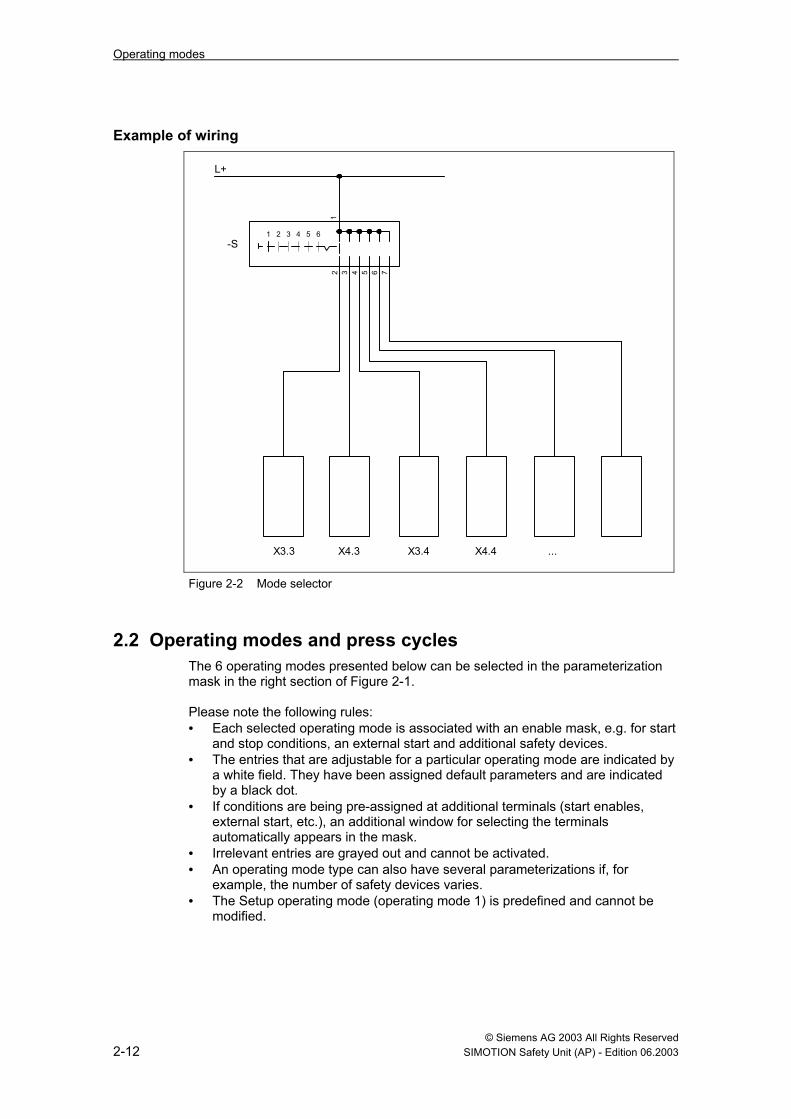
Example of wiring
L+
12 3 4 5 6 7
1 2 3 4 5 6-S
X4.3X3.3 X3.4 X4.4 ...
Figure 2-2 Mode selector
2.2 Operating modes and press cycles The 6 operating modes presented below can be selected in the parameterization mask in the right section of Figure 2-1. Please note the following rules: • Each selected operating mode is associated with an enable mask, e.g. for start
and stop conditions, an external start and additional safety devices. • The entries that are adjustable for a particular operating mode are indicated by
a white field. They have been assigned default parameters and are indicated by a black dot.
• If conditions are being pre-assigned at additional terminals (start enables, external start, etc.), an additional window for selecting the terminals automatically appears in the mask.
• Irrelevant entries are grayed out and cannot be activated. • An operating mode type can also have several parameterizations if, for
example, the number of safety devices varies. • The Setup operating mode (operating mode 1) is predefined and cannot be
modified.

Operating modes
© Siemens AG 2003 All Rights Reserved SIMOTION Safety Unit (AP) - Edition 06.2003 2-13
2.2.1 Setup (operating mode 1)
Definition The press will only move while the two-hand buttons are being pressed. This is also the case when the ram is moving upward. The press automatically comes to a standstill at the end of each stroke (TDC). The operating elements must be deactivated before a new start can be initiated. A triple-action stop during a single stroke is not required with this control unit since the Setup operating mode reaches the same level of safety as, for example, the single stroke mode.
Parameterization
Figure 2-3 Enabling of operating mode 1
Note on "Safe motion" parameterization When parameterizing "Selected safety device can be disabled via terminal", other suitable safety measures must be effective for the specific machine when this parameter is activated.

Operating modes
© Siemens AG 2003 All Rights Reserved 2-14 SIMOTION Safety Unit (AP) - Edition 06.2003
2.2.2 Single stroke (operating mode 2)
Definition Pressure must be maintained on the two-hand buttons for activating the ram until the hazardous closing movement is completed (just prior to the BDC). The press then automatically moves back to the TDC and comes to a standstill. The press can also be activated using a foot switch. In this case, however, suitable safety measures (safety gate, light curtain) must be implemented that either make it impossible to reach into the hazardous area with the hands during a closing movement or that cause the machine to come to a standstill in the event of such an action. The same applies if the "Transfer through input terminal" parameter is selected for the "Transfer of START command".
Parameterization
Figure 2-4 Enabling of operating mode 2

Operating modes
© Siemens AG 2003 All Rights Reserved SIMOTION Safety Unit (AP) - Edition 06.2003 2-15
2.2.3 Continuous stroke (operating mode 3)
Definition This operating mode requires the implementation of suitable safety measures and an automated feed and removal of parts. After a start pulse, the press continues running until it is brought to a standstill by a stop signal. Depending on the selections made in the enable mask, the press either stops in the TDC or comes to an immediate standstill.
Parameterization
Figure 2-5 Enabling of operating mode 3
Operating modes
© Siemens AG 2003 All Rights Reserved 2-16 SIMOTION Safety Unit (AP) - Edition 06.2003
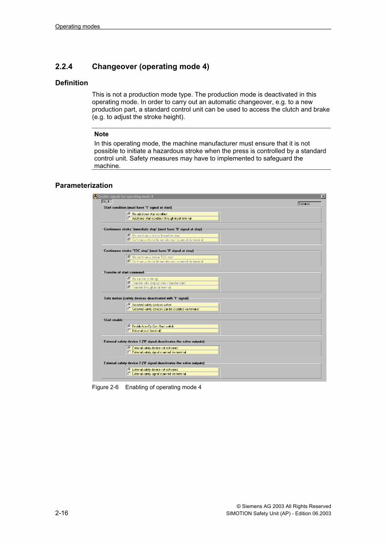
2.2.4 Changeover (operating mode 4)
Definition This is not a production mode type. The production mode is deactivated in this operating mode. In order to carry out an automatic changeover, e.g. to a new production part, a standard control unit can be used to access the clutch and brake (e.g. to adjust the stroke height).
Note In this operating mode, the machine manufacturer must ensure that it is not possible to initiate a hazardous stroke when the press is controlled by a standard control unit. Safety measures may have to implemented to safeguard the machine.
Parameterization
Figure 2-6 Enabling of operating mode 4
Operating modes
© Siemens AG 2003 All Rights Reserved SIMOTION Safety Unit (AP) - Edition 06.2003 2-17
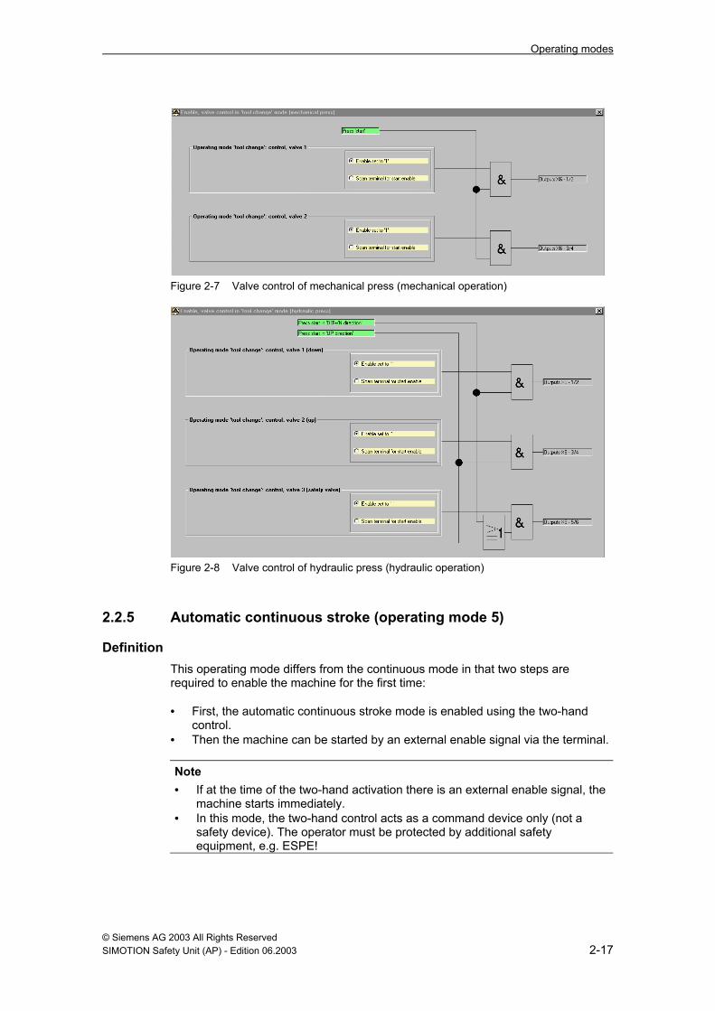
Figure 2-7 Valve control of mechanical press (mechanical operation)
Figure 2-8 Valve control of hydraulic press (hydraulic operation)
2.2.5 Automatic continuous stroke (operating mode 5)
Definition This operating mode differs from the continuous mode in that two steps are required to enable the machine for the first time: • First, the automatic continuous stroke mode is enabled using the two-hand
control. • Then the machine can be started by an external enable signal via the terminal.
Note • If at the time of the two-hand activation there is an external enable signal, the
machine starts immediately. • In this mode, the two-hand control acts as a command device only (not a
safety device). The operator must be protected by additional safety equipment, e.g. ESPE!

Operating modes
© Siemens AG 2003 All Rights Reserved 2-18 SIMOTION Safety Unit (AP) - Edition 06.2003
Operating instructions • The machine stops at the next BDC when the external enable signal ceases. It
can be restarted with this signal alone within the next 30 s. • Two switching steps (see "Definition") are always required when a restart does
not take place within the next 30 s or when a safety device or a continuous stroke stop (BDC or immediate stop) was activated.
Parameterization
Figure 2-9 Enabling of operating mode 5

Operating modes
© Siemens AG 2003 All Rights Reserved SIMOTION Safety Unit (AP) - Edition 06.2003 2-19
2.2.6 Single-stroke ESPE (operating mode 6) Using a light curtain to control the press is described in the Control Elements chapter.
Parameterization
Figure 2-10 Enabling of operating mode 6

Operating modes
© Siemens AG 2003 All Rights Reserved 2-20 SIMOTION Safety Unit (AP) - Edition 06.2003
Notes

© Siemens AG 2003 All Rights Reserved SIMOTION Safety Unit (AP) - Edition 06.2003 3-21
3 Safety components
The contacts can be wired directly in the control unit. Additional contactors or relays are not required. The following cyclical monitoring procedures are performed in the program: • Short circuit monitor between the two mutually isolated signal circuits. • Discrepancy check of whether both switch-off circuits carry out a signal
change when the button is activated. The change between the two signals is also monitored over time. The only elements that do not adhere to the preset discrepancy time are the safety gate components.
The following components are available and can be combined as required: • EMERGENCY OFF with restart inhibit (4x) • EMERGENCY OFF without acknowledge (4x) • Engaging lock (without acknowledge) (2x) • Safety guard with restart inhibit (4x) • Safety guard without acknowledge (4x) • Safety gate with manual acknowledge (3x) • Safety gate without manual acknowledge (3x) Light curtains that are only used in the safety mode can be connected to the existing safety guard components. For a description of their mode of operation, see the Operating Elements chapter. The parameterization of light curtains that are switched in safety and clock mode is presented in the Operating Elements chapter.
Comments • The EMERGENCY OFF that is activated in the parameterization is always
active for the entire control unit. It can, however, be deactivated for individual operating modes (e.g. useful when creating different EMERGENCY OFF circuits).
• The same applies to the engaging lock and the safety gate and safety guard components. In this case, the safety devices can be specifically deselected in the operating modes in which they are to be inactive.
Note
Without the implementation of additional safety measures, safety gates and safety guards without a restart inhibit are not suitable for hazardous areas that can be walked through.
3

Safety components
© Siemens AG 2003 All Rights Reserved 3-22 SIMOTION Safety Unit (AP) - Edition 06.2003
3.1 Parameterization of safety components
Figure 3-1 EMERGENCY OFF safety functions
Figure 3-2 Safety guard safety functions

Safety components
© Siemens AG 2003 All Rights Reserved SIMOTION Safety Unit (AP) - Edition 06.2003 3-23
Comment If the EMERGENCY OFF or the "Safety guard with restart inhibit" is selected, a flashing fault lamp or, optionally, a separate alarm lamp (parameterizable) indicates that the system is ready for acknowledgement.
Figure 3-3 Safety gate safety functions
Note on safety gate with manual acknowledgement Both contacts must be activated to open the safety gate. If only one contact is activated and reclosed, an alarm is output with a continuous light. In this case, both contacts will then have to be opened and reclosed. The continuous light goes out after both contacts have been properly opened. When the contacts are closed, a flashing signal indicates that the safety gate is ready for acknowledgement. After the acknowledge button has been activated, the machine is again ready to be started. For safety gates without acknowledgement, there is no display if only one contact is opened and reclosed due to an operation error. The problem is eliminated by completely opening and reclosing the gate.
Figure 3-4 Engaging lock safety functions

Safety components
© Siemens AG 2003 All Rights Reserved 3-24 SIMOTION Safety Unit (AP) - Edition 06.2003
3.2 Example of safety component wiring
L+
L+
Clock voltage
X2.5X2.1
X3.5 X4.5 Figure 3-5 Example of EMERGENCY OFF wiring

Safety components
© Siemens AG 2003 All Rights Reserved SIMOTION Safety Unit (AP) - Edition 06.2003 3-25
L+
L+
Clock voltage
X2.6X2.2
X3.6 X4.6 Figure 3-6 Example of safety guard wiring

Safety components
© Siemens AG 2003 All Rights Reserved 3-26 SIMOTION Safety Unit (AP) - Edition 06.2003
Notes

© Siemens AG 2003 All Rights Reserved SIMOTION Safety Unit (AP) - Edition 06.2003 4-27
4 Control elements
4.1 Two-hand control
Definition It must be ensured that the operator is not located within the hazardous area during the press cycle. To guarantee this, the operator must press both engagement buttons within 500 ms of each other to initiate a press stroke. These engagement commands are edge controlled so that even if only one engagement button is released briefly, the engagement command is disabled. The period of 500 ms during which the system is ready to switch on begins as soon as the button is activated and is reset when both buttons are in the neutral position and one button is reactivated. The two-hand engagement command is only generated if the two-hand activation has been simultaneous and if both engagement buttons are activated.
Operating instructions • A maximum of 3 two-hand consoles can be connected. • Each console has its own two-hand function. • It is possible to use consoles that can be plugged in. Plug-in monitoring takes
place via the NC and NO contacts of the two-hand buttons. This eliminates the need for an additional contact for plug-in monitoring.
• A keyswitch is needed to activate and deactivate a console. The console that is plugged in must match the preselected console.
• If you wish to switch off the two-hand console, the input must be parameterized for a console switch-off and you must also specify whether the switch-off takes place via an NC or NO contact. Console deactivation is implemented via a high level at the activation and deactivation input (fail safe).
• The operating modes in which the two-hand buttons are to be disabled are selected on the right side of the parameterization mask.
4

Control elements
© Siemens AG 2003 All Rights Reserved 4-28 SIMOTION Safety Unit (AP) - Edition 06.2003
Parameterization
Figure 4-1 Two-hand control
Example of wiring
Clock voltage
X3.1 X3.2 X4.1 X4.2
L+
L+
L+
L+X2.5X2.6X2.1X2.2
Figure 4-2 Two-hand control

Control elements
© Siemens AG 2003 All Rights Reserved SIMOTION Safety Unit (AP) - Edition 06.2003 4-29
4.1.1 Determining the safety distance The reaction times of the control unit and the machine must be considered when determining the safety distance. The reaction time and the resulting safety distance can be calculated using the following equation: S = (T2 + T3) * vg S: Safety distance T2: Reaction time of control unit T3: Reaction time of machine vg: Activation time (1.6 m/s according to EN 999) Example: T2 according to Safety Unit data sheet connection of the lag meter for determining the reaction time of the machine (empirical T3 measurement) use the poorest of 10 measurement values!
Control unit
Machine

Control elements
© Siemens AG 2003 All Rights Reserved 4-30 SIMOTION Safety Unit (AP) - Edition 06.2003
4.2 Foot switch This has the same function as the two-hand control with the exception that it has only one NC and one NO contact. A maximum of 3 foot switches can be connected.
Parameterization
Figure 4-3 Operation of the foot switch
Control elements
© Siemens AG 2003 All Rights Reserved SIMOTION Safety Unit (AP) - Edition 06.2003 4-31
Example of wiring
L+
Clock voltageX2.5X2.1 L+
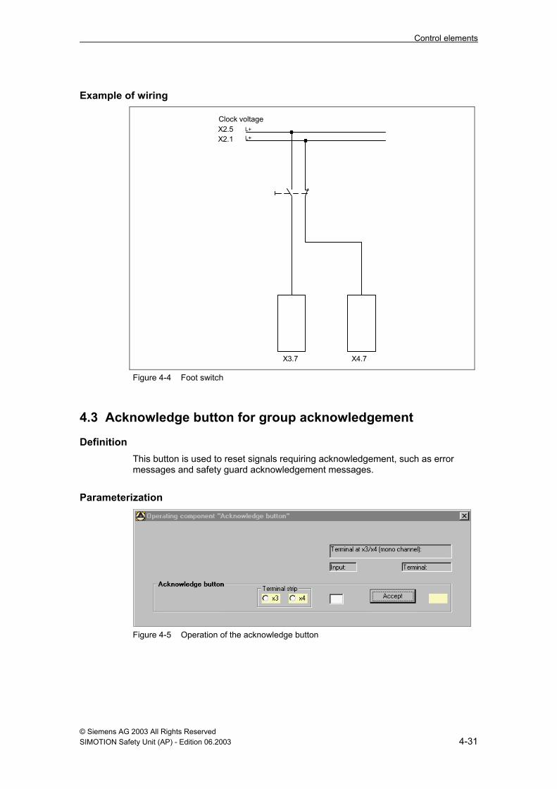
X3.7 X4.7 Figure 4-4 Foot switch
4.3 Acknowledge button for group acknowledgement
Definition This button is used to reset signals requiring acknowledgement, such as error messages and safety guard acknowledgement messages.
Parameterization
Figure 4-5 Operation of the acknowledge button

Control elements
© Siemens AG 2003 All Rights Reserved 4-32 SIMOTION Safety Unit (AP) - Edition 06.2003
4.4 Electro-sensitive protective equipment (ESPE)
Definition These primarily include safety light curtains or light barriers that monitor access to the hazardous areas of the press. These light curtains are intrinsically safe, i.e. in the event of a malfunction they go into a safe state and they have certified their suitability for presses by means of type examinations (confirmed by test certificates).
Operating instructions The light curtain provides two "light path unobstructed“ channels.
• In some light curtains with semiconductor outputs, the short circuit test for both channels is already integrated. In this case, the short circuit monitor of the control unit should be switched off!
• When using light curtains with relay outputs, the short circuit monitor of the control unit must be active!
It is the task of the press safety control unit to correctly interpret the output signal of the light curtain and to generate from it the subsequent operation and control of the press safety valve. Light curtains can be operated in: • safety mode, as a substitute for a permanently-closed safety gate (see the
Safety Components chapter) • control mode. In this mode, the operator can reach into the protective zone
when the press is at a standstill in the TDC position in order to remove parts or add material. After the operator leaves the protected area, the press automatically resumes operation. Reaching into the machine while the ram is descending causes the press to come to an immediate standstill. In the control mode, there is both a single-stroke mode and a two-stroke mode. Which mode is selected depends on whether a separate step is required when material is fed to the machine during which the operator leaves the protective zone.
The following light curtains have been tested with the control unit: - Type 3RG78..., by Siemens in safety or clock mode (clock mode as of July 03) - TypeC4000 advanced, by Sick in safety or clock mode Others upon request

Control elements
© Siemens AG 2003 All Rights Reserved SIMOTION Safety Unit (AP) - Edition 06.2003 4-33
4.4.1 Determining the safety distance with ESPE The reaction times of the ESPE, the control unit and the machine must be considered when determining the safety distance. The reaction time and the resulting safety distance can be calculated using the following equation: S = (T1 + T2 + T3) * vg + k S: Safety distance T1: Reaction time of the ESPE T2: Reaction time of control unit T3: Reaction time of machine vg: Activation time (1.6 m/s or 2.0 m/s according to EN 999) k : Addition for resolving power of the ESPE k = 8 * (p-14); p: Resolving power of the ESPE Example: T1 according to manufacturer data sheet T2 according to Safety Unit data sheet connection of lag meter for determining the reaction time of the machine (empirical T3 measurement)
use the poorest of 10 measurement values!
Control unit
Machine
ESPE

Control elements
© Siemens AG 2003 All Rights Reserved 4-34 SIMOTION Safety Unit (AP) - Edition 06.2003
4.5 Control function with light curtain
4.5.1 Mode selector The mode selector (single stroke and two-stroke) is connected to simple digital inputs. A short circuit between these signals is identified by means of the "1 of 2" selection. An intermediate position is not required.
Comment The light curtain receives its voltage supply from the Safety Unit through output X2.x. Therefore, the light curtain is without voltage when the mode selector is set to "Off".
Note
If the light curtain is not active, the power supply for the light curtain must be switched off so that the unlit LED will indicate to the operator that the light curtain is not operational.
4.5.2 Modes for clock operation
Definition There are two modes for clock operation – the standard mode and the Sweden mode. The only difference between the two modes is in the manner in which they start after a restart inhibit.
Standard mode In the standard mode, an interruption of the light field is initially required before starting the machine or before starting it after a restart inhibit. After that, the first start of the press must be initiated by the command device. The two-hand switch is provided for this purpose.
Sweden mode In the Sweden mode, a command device acknowledgement is required before starting the machine or before starting it after a restart inhibit. The press is then started by interrupting the light field (interrupting it twice in the case of the two-stroke mode).
4.5.3 Starting the press in clock mode In clock mode, the press is started after one or two interruptions of the light field. The following conditions apply for these interruptions: • The prerequisites for the first start must be met. • The interruption must last longer than 100 ms. • The interruption must take place at the top dead center. • The previous interruption may not lie farther back than 30 s.

Control elements
© Siemens AG 2003 All Rights Reserved SIMOTION Safety Unit (AP) - Edition 06.2003 4-35
4.5.4 Restart inhibit of light curtain in clock mode The restart inhibit is indicated by a flashing fault lamp and is activated in the following cases: • Start of the Safety Unit after a power off or stop (keyswitch position). • In the event that the operating mode is changed on the selection switch of the
light curtain. In the clock mode, if there is an interruption during a hazardous movement.
• In the clock mode, in the event that there is no intervention for more than 30 s. The restart inhibit is acknowledged by the command device. Either a separate button or a two-hand control can be used as a command device.
Parameterization
Figure 4-6 Operating the light curtain
Control elements
© Siemens AG 2003 All Rights Reserved 4-36 SIMOTION Safety Unit (AP) - Edition 06.2003
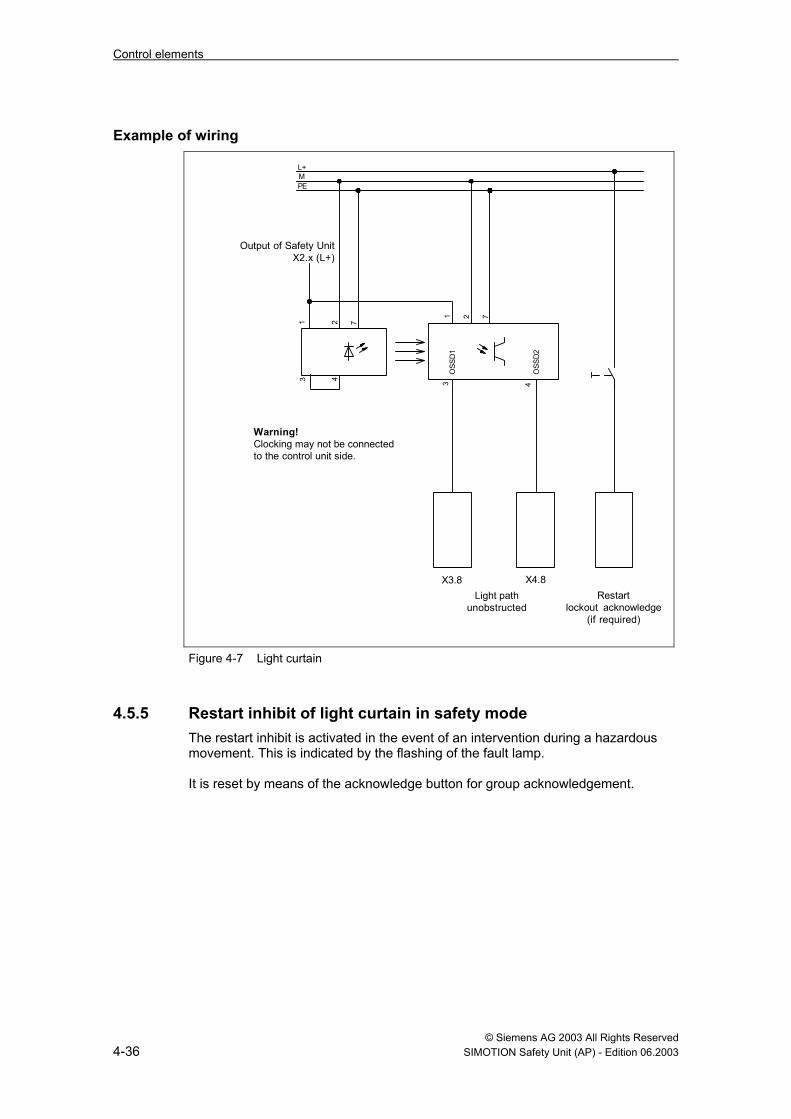
Example of wiring
Restartlockout acknowledge
(if required)
L+MPE
Light pathunobstructed
X3.8 X4.8
Warning!Clocking may not be connectedto the control unit side.
1 2 7
1 2 7
3 4
43O
SSD
1
OSS
D2
Output of Safety Unit X2.x (L+)
Figure 4-7 Light curtain
4.5.5 Restart inhibit of light curtain in safety mode The restart inhibit is activated in the event of an intervention during a hazardous movement. This is indicated by the flashing of the fault lamp. It is reset by means of the acknowledge button for group acknowledgement.

Control elements
© Siemens AG 2003 All Rights Reserved SIMOTION Safety Unit (AP) - Edition 06.2003 4-37
4.6 EMERGENCY OFF output signal This function is used for the external processing of the control unit EMERGENCY OFF signal. The control command to a contactor combination must correspond to the feedback within a certain adjustable time period.
Attention This function is not activated until after the feedback input has been parameterized.
Parameterization
Figure 4-8 Mechanical operation – EMERGENCY OFF output signal See also Figure 5-6.
Note • The discrepancy time between the activation of the outputs and the signaling
of the feedback input depends on the response times of the contactors in use. Typical values lie between 50 ms and 200 ms. Therefore, this maximum value should not be exceed in the parameterization.
• The Safety Unit ensures there will be an output signal in Category 4. Systems connected downstream must be designed in the category they require.
• After the Safety Unit restarts, the output signal for output activation must be acknowledged if the output signal has been parameterized for that mode.
• If the output signal has not been parameterized in a certain mode, it is reset when that mode is activated. If the output signal is activated using a mode selector, it is not activated until after acknowledgement.
• The acknowledgement request is output via the corresponding message.

Control elements
© Siemens AG 2003 All Rights Reserved 4-38 SIMOTION Safety Unit (AP) - Edition 06.2003
Example of wiring
L+
(P)
-K10
A
61 62
-K10
B
61 62
(M)
-K10
A
13 14
-K10
B
13 14
23 24 23 24
33 34 33 34
EMER
GEN
CY
OFF
cont
acts
,e.
g. fo
r loa
d vo
ltage
-S
X6.
7X6
.8
Con
tact
or r
elay
feed
back
EMER
GEN
CY O
FFac
know
ledg
e
X3.
11
-K10
A
A2 A1
-K10
B
A1 A2
Figure 4-9 EMERGENCY OFF output signal
© Siemens AG 2003 All Rights Reserved SIMOTION Safety Unit (AP) - Edition 06.2003 5-39
5 Procedural functions of mechanical presses
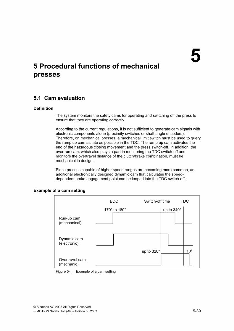
5.1 Cam evaluation
Definition The system monitors the safety cams for operating and switching off the press to ensure that they are operating correctly. According to the current regulations, it is not sufficient to generate cam signals with electronic components alone (proximity switches or shaft angle encoders). Therefore, on mechanical presses, a mechanical limit switch must be used to query the ramp up cam as late as possible in the TDC. The ramp up cam activates the end of the hazardous closing movement and the press switch-off. In addition, the over run cam, which also plays a part in monitoring the TDC switch-off and monitors the overtravel distance of the clutch/brake combination, must be mechanical in design. Since presses capable of higher speed ranges are becoming more common, an additional electronically designed dynamic cam that calculates the speed-dependent brake engagement point can be looped into the TDC switch-off.
Example of a cam setting
up to 320° 10°
Overtravel cam (mechanic)
Dynamic cam (electronic)
up to 340° 170° to 180°
Run-up cam (mechanical)
BDC TDC Switch-off time
Figure 5-1 Example of a cam setting
5

Procedural functions of mechanical presses
© Siemens AG 2003 All Rights Reserved 5-40 SIMOTION Safety Unit (AP) - Edition 06.2003
In the case of fixed stroke speeds without dynamic cams, the TDC switch-off occurs on the leading edge of the over run cam. For the TDC stop at variable stroke speeds, a separate electronic cam switchgear is provided that calculates the brake engagement point from the stroke speed. This dynamic cam switches in the range of 320° to 340°, for example, and takes over the TDC switch-off on a falling edge.
Parameterization
Figure 5-2 Mechanical operation – Cam monitoring system

Procedural functions of mechanical presses
© Siemens AG 2003 All Rights Reserved SIMOTION Safety Unit (AP) - Edition 06.2003 5-41
Example of wiring
L+L+
Clock voltage
Run-up cam
X3.9
Dynamic TDCswitch-off
Electronic cam switchgear,PLC or initiator
Overtravel cam
X3.10
Figure 5-3 Cam evaluation
Procedural functions of mechanical presses
© Siemens AG 2003 All Rights Reserved 5-42 SIMOTION Safety Unit (AP) - Edition 06.2003
5.2 Speed monitor
Definition The safety cams are mounted on a shaft in the mechanical cam switchgear. During rotation, the speed monitor at the end of this shaft generates pulses that are monitored. Should the pulses cease, e.g. in the case of a shaft break or faulty timing belt, the press comes to an immediate standstill. The "Speed monitor“ function can only be deselected if the safety cams are mounted directly on the main drive shaft.
Operating principle of the monitor A proximity switch at the cam controller (30 pulses per stroke) is used to monitor a shaft break using an adjustable time interval. If the monitor does not detect at least one pulse during this interval, the press is brought to a standstill.
Functional description of the monitor An encoder that outputs 30 pulses per rotation is integrated in each cam switchgear. These pulses are used to check whether the shaft or the cam switchgear is defective. The encoder must be connected to the hardware counter of the Safety Unit, terminal X9. The cam switchgear expects to receive pulses when the press ram is moved. The monitor checks whether at least one pulse is counted during the adjustable time periods. If not, an error is output that causes the machine to be brought to an immediate standstill. The time intervals must be set to the working speed of the machine and must be kept as small as possible for the slowest machine speed. The overtravel angle may not exceed 90°.
Parameterization
Figure 5-4 Mechanical operation – Speed monitor
Procedural functions of mechanical presses
© Siemens AG 2003 All Rights Reserved SIMOTION Safety Unit (AP) - Edition 06.2003 5-43
Example of wiring
L+M
-B+-1
X9.2 X9.7
Figure 5-5 Speed monitor
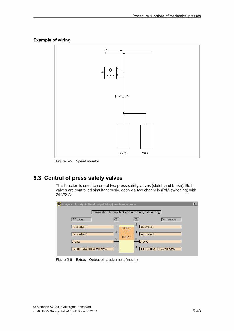
5.3 Control of press safety valves This function is used to control two press safety valves (clutch and brake). Both valves are controlled simultaneously, each via two channels (P/M-switching) with 24 V/2 A.
Figure 5-6 Extras - Output pin assignment (mech.)

Procedural functions of mechanical presses
© Siemens AG 2003 All Rights Reserved 5-44 SIMOTION Safety Unit (AP) - Edition 06.2003
Example of wiring
-Y01
1 2 PSV1
-Y02
1 2 PSV2
L+ M
-BY0
1+ - 1
-BY0
2+ - 1
Posi
tion
feed
back
of
pres
s sa
fety
val
ve (
if pr
esen
t)
X6.
1X
6.2
X6.
3X
6.4
X4.
10X
4.11
Figure 5-7 Press safety valves

Procedural functions of mechanical presses
© Siemens AG 2003 All Rights Reserved SIMOTION Safety Unit (AP) - Edition 06.2003 5-45
5.4 Valve monitoring If, for mechanical safety reasons, the clutch/brake-combination is equipped with limit switches that display the switching position of the valves, these are read in via the feedback inputs in the control unit and compared to the activation of the outputs (watchdog timer).
Note If an electrical valve monitor is not in use, monitoring must be accomplished by means of other measures with a comparable degree of safety (hydraulic or electric).
Parameterization
Figure 5-8 Mechanical operation – Watchdog timer

Procedural functions of mechanical presses
© Siemens AG 2003 All Rights Reserved 5-46 SIMOTION Safety Unit (AP) - Edition 06.2003
Notes

© Siemens AG 2003 All Rights Reserved SIMOTION Safety Unit (AP) - Edition 06.2003 6-47
6 Procedural functions of hydraulic presses
6.1 Control of valves for hydraulic presses
Definition This function controls the following elements: • Directional valves for both the upward and downward movement • Safety valves
Operating instructions • This function can be used to activate 3 different valves (or double valves). • Each valve is controlled via two channels (P/M-switching) with 24 V/2 A. • Single channel inputs are the reversing point in the TDC and BDC. • In the case of an automatic takeover, the "Safety point" and "Pressure value"
signals must be queried on the input side. • In "Setup" mode, activation of the two-hand switch or the foot switch causes
the press to move to BDC (inching). An upward movement is brought about by activating the "UP button".
Note on the wiring of the "Takeover point"
The "Safety point" and "Pressure value" signals are evaluated at the takeover point. To detect a short circuit between these two signals, one of them must be supplied via the encoder clock (e. g. by using a mechanical switch).
Parameterization
Figure 6-1 Extras - Output pin assignment (hydr.)
6

Procedural functions of hydraulic presses
© Siemens AG 2003 All Rights Reserved 6-48 SIMOTION Safety Unit (AP) - Edition 06.2003
Figure 6-2 Hydraulic operation – End-of-stroke signals
6.2 Valve monitoring
Parameterization
Figure 6-3 Hydraulic operation – Watchdog timer
Note If an electrical valve monitor is not in use, monitoring must be accomplished by means of other measures with a comparable degree of safety (hydraulic or electric).

Procedural functions of hydraulic presses
© Siemens AG 2003 All Rights Reserved SIMOTION Safety Unit (AP) - Edition 06.2003 6-49
Example of wiring
-Y01
1 2 PSV1
L+ M
-BY0
1+ - 1
Pos
ition
feed
back
of p
ress
safe
ty v
alve
(if
pres
ent)
X6.
1
X4.
10
X6.2
-Y02
1 2 PSV2
X6.
3X
6.4
-Y02
1 2 PSV3
X6.
5X
6.6
-BY0
2+ - 1 X
4.11
-BY0
3+ - 1 X
4.12
Figure 6-4 Valve monitoring

Procedural functions of hydraulic presses
© Siemens AG 2003 All Rights Reserved 6-50 SIMOTION Safety Unit (AP) - Edition 06.2003
Notes

© Siemens AG 2003 All Rights Reserved SIMOTION Safety Unit (AP) - Edition 06.2003 7-51
7 Procedural functions of press brakes
7.1 Selecting the operating mode • Up to 6 operating modes can be parameterized. • For press brakes, operating modes 1-6 are equivalent and have no special
functions. • The only exception is operating mode 1, which is intended for fault
acknowledgement.
7.2 Protective features The protective features (EMERGENCY OFF, EMERGENCY OFF output signal, safety guard, safety gate, engaging lock) do not require special handling for the folding functionality.
7.3 Control elements The control elements (two-hand control, foot switch, acknowledge button for group acknowledgement) do not require special handling for the folding functionality.
7

Procedural functions of press brakes
© Siemens AG 2003 All Rights Reserved 7-52 SIMOTION Safety Unit (AP) - Edition 06.2003
7.4 Generating enables An "Enable signals for operating mode (1-6)" mask is assigned to each operating mode. The operating modes are handled identically.
Parameterization
Figure 7-1 Enabling for operating modes
7.4.1 Information on control signals • Start condition
The "Start condition" signal is an enable signal for the downward movement. It must be available prior to every start of a downward movement (HIGH level), but can change its state during the movement. This function can be disabled when no additional start condition is required (default).

Procedural functions of press brakes
© Siemens AG 2003 All Rights Reserved SIMOTION Safety Unit (AP) - Edition 06.2003 7-53
• Request "DOWN" The "DOWN" request signal is the start command from the higher level control to the Safety Unit for initiating the downward movement. There must be an enable signal from the Safety Unit for the downward movement. The "DOWN" request signal must be active for the duration of the downward movement. The press is stopped on a falling edge (operational stop). If the request for the downward movement will not be read in by a higher level control, this function can be disabled (default).
• Request "UP"
The "UP" request signal is the start command from the higher level control to the Safety Unit for initiating the upward movement (see Figure 7-7 Valve control, Part 3). The signal must be active for the duration of the upward movement. The press is stopped on a falling edge.If valves will not be controlled by the Safety Unit during the upward movement, this function can be disabled (default). The upward movement is not a safety-oriented function and can be implemented by a higher level control. In Chapter 7.5.4, the valve (valve pair) that is to be controlled during the upward movement can be assigned.
• Request "fast downwards speed"
The "Fast downwards speed" request signal is the command from the higher lever control to the Safety Unit for activation of the fast downward movement. The signal must be active for the duration of the fast downward movement. In the case of a LOW level, the downward movement is always slow. If the enable for the fast downward movement is to be generated internally, this function can be disabled (default).
Note
Information on enabling the fast downward movement are found in Chapter 7.6.1 "Conditions for fast downward movements".
• "MUTE point"
The "MUTE point" initiates the press movement. The MUTE point signal is LOW active. It must provide a HIGH level for the duration of the fast downward movement. In the case of a LOW level, the downward movement is always slow. If the MUTE point is approached with a fast downward movement, the system changes to a slow movement. If the "Two-hand foot-operation" function (see Chapter "Conditions for fast downward movement") is to be implemented, the MUTE point must be parameterized. The rapid downward movement with 2-hand operation is interrupted at the MUTE point. The "MUTE point" function can be deactivated (default).
• Jog mode – for "multi-operator control"
In jog mode, a control element (hand or foot) can remain activated with multi-operator control. A jog function can be implemented with the second control element. This function is primarily used during press motion. If the job mode is activated during the fast downward movement, the system automatically

Procedural functions of press brakes
© Siemens AG 2003 All Rights Reserved 7-54 SIMOTION Safety Unit (AP) - Edition 06.2003
changes to the slow downward movement. This function can be deactivated (default).
• External safety device 1 (2)
This signal can be used to query 2 one-channel safety devices. A LOW level at one of the inputs de-energizes the valves. This can be used, for example, to implement a "Tilt monitor" (Chapter 7.6.2).
7.5 Folding function Functions specific to die bending presses are parameterized in the "Folding function" menu. These functions include: • Access protection (moving safety devices, distance protection) • Valve monitor (watchdog or dynamic) • Emergency off output signal • Valve control
7.5.1 Access protection
Figure 7-2 Access protection Two safety devices can be parameterized for access protection (light curtain or laser safety device). Each access protection can be activated as required for the mode. If the access protection is deactivated in a specific operating mode, it must be switched off. Preferably this will be implemented via the ESPE supply (0.5 A output). One dual-channel input is used per access protection. The fast downward movement for foot operation is only possible when the access protection is active (for exceptions, see Chapter 7.6.1). If access protection 1 and access protection 2 are active in a particular operating mode, they are ANDed. A falling edge on an active access protection de-energizes the valves. The access protection is not evaluated beyond the mute point (function required for light curtain).

Procedural functions of press brakes
© Siemens AG 2003 All Rights Reserved SIMOTION Safety Unit (AP) - Edition 06.2003 7-55
7.5.2 Watchdog timer
Figure 7-3 Watchdog timer The run time of three valves can be monitored. The valve run time can be variably parameterized from 20 to 2000 ms. The feedback input can be defined as an NO or NC contact.

Procedural functions of press brakes
© Siemens AG 2003 All Rights Reserved 7-56 SIMOTION Safety Unit (AP) - Edition 06.2003
7.5.3 Dynamic valve monitoring
Figure 7-4 Dynamic valve monitoring Three valves can be monitored dynamically. Switching is monitored every time the corresponding valve is activated. The feedback input can be defined as an NO or NC contact. To be able to control the valve, the read back input must be at LOW level before the valve is activated. During switching, at least one leading edge must be received at the read back input (for NO contact.
Note
The valve can be activated on short start pulses from the command devices, but it does not switch through due to valve run times. Since in this case there would also be no feedback at the read back input, this would result in a valve switching fault. For this reason, a response delay can be parameterized for the valve. The response delay for the valve monitor can be variably set to between 20 and 2000 ms.

Procedural functions of press brakes
© Siemens AG 2003 All Rights Reserved SIMOTION Safety Unit (AP) - Edition 06.2003 7-57
7.5.4 Valve control
Figure 7-5 Valve control, part 1 The valve control can be implemented in accordance with performance requirements. A maximum of 3 valve pairs can be controlled. For the switching variant on the left, the maximum possible output current is doubled (with equal loading of both the P and M switches).
Figure 7-6 Valve control, part 2 One of two valve control variants can be selected: • Variant 1
Here the press safety valve and valve 1 (or valve pair 1) are controlled for the slow downward movement. All 3 valves (or valve pairs) are controlled for the fast downward movement.
• Variant 2
Here the press safety valve and valve 1 (or valve pair 1) are controlled for the slow downward movement. The press safety valve and valve 2 (or valve pair 2) are controlled for the fast downward movement. For this variant, it can optionally be specified whether valve 1 (slow movement) is to remain controlled after activation. The control is reset as soon as a safety device "responds", the "fast" request is set, the upward movement is initiated or the operating mode is changed.
Procedural functions of press brakes
© Siemens AG 2003 All Rights Reserved 7-58 SIMOTION Safety Unit (AP) - Edition 06.2003
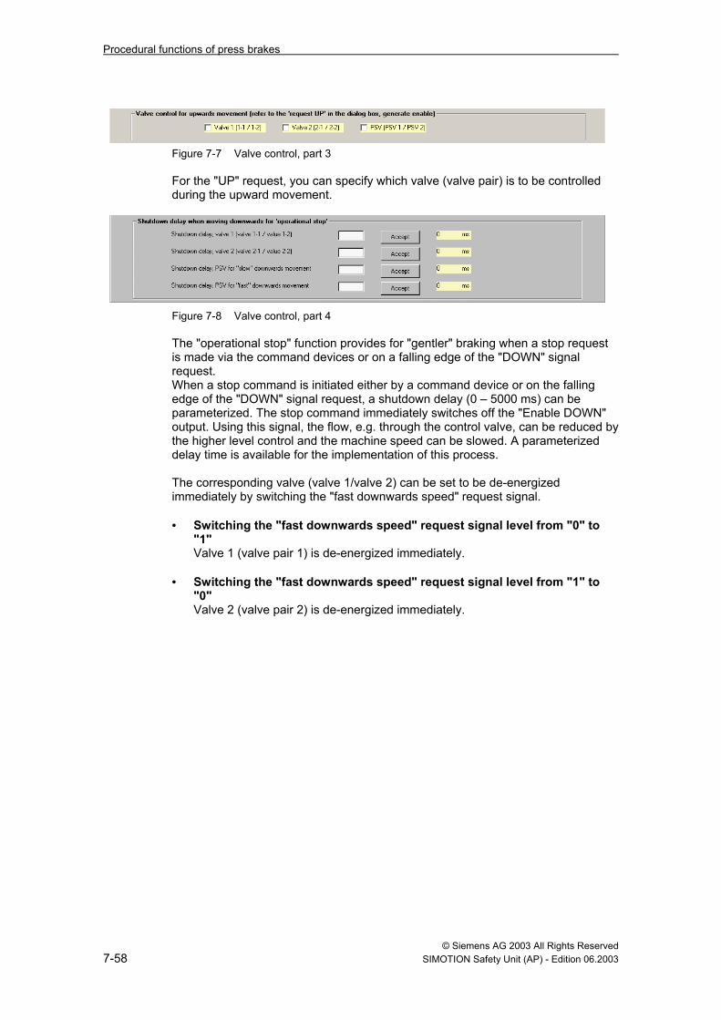
Figure 7-7 Valve control, part 3 For the "UP" request, you can specify which valve (valve pair) is to be controlled during the upward movement.
Figure 7-8 Valve control, part 4 The "operational stop" function provides for "gentler" braking when a stop request is made via the command devices or on a falling edge of the "DOWN" signal request. When a stop command is initiated either by a command device or on the falling edge of the "DOWN" signal request, a shutdown delay (0 – 5000 ms) can be parameterized. The stop command immediately switches off the "Enable DOWN" output. Using this signal, the flow, e.g. through the control valve, can be reduced by the higher level control and the machine speed can be slowed. A parameterized delay time is available for the implementation of this process. The corresponding valve (valve 1/valve 2) can be set to be de-energized immediately by switching the "fast downwards speed" request signal.
• Switching the "fast downwards speed" request signal level from "0" to
"1" Valve 1 (valve pair 1) is de-energized immediately.
• Switching the "fast downwards speed" request signal level from "1" to
"0" Valve 2 (valve pair 2) is de-energized immediately.

Procedural functions of press brakes
© Siemens AG 2003 All Rights Reserved SIMOTION Safety Unit (AP) - Edition 06.2003 7-59
7.6 Information on functionality
7.6.1 Conditions for fast downward movements • Foot control
To be able to initiate a rapid downward movement by foot control, the access protection that is activated in the respective operating mode must supply the enable (HIGH level). If access protection has not been parameterized in the respective operating mode, a fast downward movement cannot be initiated by foot control.
• Two-hand control (two-hand/foot control) According to the EN 12622 standard, two-hand control is only permissible in the Setup mode. If the fast downward movement is to be initiated by two-hand control up to the MUTE point during operation, access protection is not required. A MUTE point must be parameterized for this function. Switching of the valve is initiated at the MUTE point (slow speed). A stop can now be initiated via the "DOWN" request signal and control can be switched to foot control (foot mode ).
7.6.2 Tilt monitor
Figure 7-9 Tilt monitor Two one-channel proximity switches can be connected under the "Generate enable" menu item using the two external safety devices. This function is fail-safe (HIGH level for enable). The proximity switches must be installed on the machine according to the desired maximum tilt.

Procedural functions of press brakes
© Siemens AG 2003 All Rights Reserved 7-60 SIMOTION Safety Unit (AP) - Edition 06.2003
7.6.3 "Moving" and "distance" access protection In the following figure, two safety devices can be parameterized for access protection for an operating mode. If both are parameterized in the same operating mode, the enable is ANDed. A falling edge at one of the safety devices always brings about a stop. To enable the fast downward movement, the safety devices parameterized in the respective operating mode must provide a HIGH level signal. Application example: Activation of distance protection (zone protection) from the MUTE point onward.
Figure 7-10 Distance protection In this example, the downward movement was started in mode 2 (e. g. foot). The "DOWN" request signal of the higher level control is reset at the MUTE point (or any point). This brings about a machine stop. The system can then switch to operating mode 3. Access protection 2 is now active. In this case, a MUTE point cannot be parameterized in operating mode 3 since access protection would otherwise be deactivated beginning with the MUTE point.

Procedural functions of press brakes
© Siemens AG 2003 All Rights Reserved SIMOTION Safety Unit (AP) - Edition 06.2003 7-61
7.7 Application examples and procedural functions The application examples apply to a handshake with a higher level process control.
7.7.1 Single operator control with foot switch
Inputs: UPPER POINT MUTE POINT END STROKE
EMERGENCY OFF switch
Access protection E1
Access protection E2
Operating mode 2
Foot NO (1) Foot NC (1) 'DOWN' request 'Fast downwards movement' request
Outputs: 'DOWN' enable Valve 1 (slow) Press safety valve Valve 2 (fast) Emergency off output signal
Figure 7-11 Example for foot switch For this example, it is assumed that a foot switch and an access protection (dual-channel E1/E2) have been parameterized for mode 2. The valves are controlled via variant 2.

Procedural functions of press brakes
© Siemens AG 2003 All Rights Reserved 7-62 SIMOTION Safety Unit (AP) - Edition 06.2003
7.7.2 Multiple operator control with foot switch Inputs: UPPER POINT MUTE POINT END
STROKE EMERGENCY OFF switch
Access protection E1
Access protection E2
Operating mode 4
Foot NO (1)
Foot NC (1)
Foot NO (2)
Foot NC (2)
'DOWN' request
'Fast downwards movement' request
Outputs:
'DOWN' enable
Valve 1 (slow)
Press safety valve
Valve 2 (fast)
Emergency off output signal
Figure 7-12 Example for multiple operators with foot switch For this example, it is assumed that two foot switches and an access protection (dual-channel E1/E2) have been parameterized for mode 4. The valves are controlled via variant 2.

© Siemens AG 2003 All Rights Reserved SIMOTION Safety Unit (AP) - Edition 06.2003 8-63
8 General functions
8.1 Single operator/multi-operator control
Figure 8-1 Implementation of single operator/multi-operator control In the above configuration, operating mode 2 is set for single operator/multi-operator control. Foot switch 2 can be selected using an NO contact (it can be deactivated). The deactivation input should be switched by the selector switch for single operator/multi-operator control.
8

General functions
© Siemens AG 2003 All Rights Reserved 8-64 SIMOTION Safety Unit (AP) - Edition 06.2003
• Multi-operator control Multi-operator control (2-foot) is activated when operating mode 2 is selected and foot switch 2 is not deactivated. In this case, if foot switch 2 is not connected, a corresponding message is output and the valves cannot be controlled (contact monitor).
• Single operator control
Single operator control (foot) is activated when operating mode 2 is selected and control element 2 is deactivated. In this case, if foot switch 2 is not connected, a corresponding message is output and the valves cannot be controlled (connection monitor).
Note
• The connection monitor checks whether, for single operator control, all other control elements (deactivated control elements) have been removed.
• For multi-operator control, all activated control elements must be connected (contact monitor).
• If the monitoring function responds, messages are output to notify the user.
8.2 Single operator control via 2 foot switches and operating error monitor To implement single operator control via 2 separate foot switches, each foot switch must be parameterized in a separate operating mode (e.g. foot switch 1 in operating mode 2 and foot switch 2 in operating mode 3). A complete stroke can be performed in operating mode 2 (foot switch 1). Subsequently, the operating mode can be changed and a complete stroke can be performed in operating mode 3 (foot switch 2). If operating mode 2 is active and foot switch 2 was activated, a suitable message is output and the machine is prevented from starting. The system stops if a control element that was not selected is activated during a press movement.
General functions
© Siemens AG 2003 All Rights Reserved SIMOTION Safety Unit (AP) - Edition 06.2003 8-65
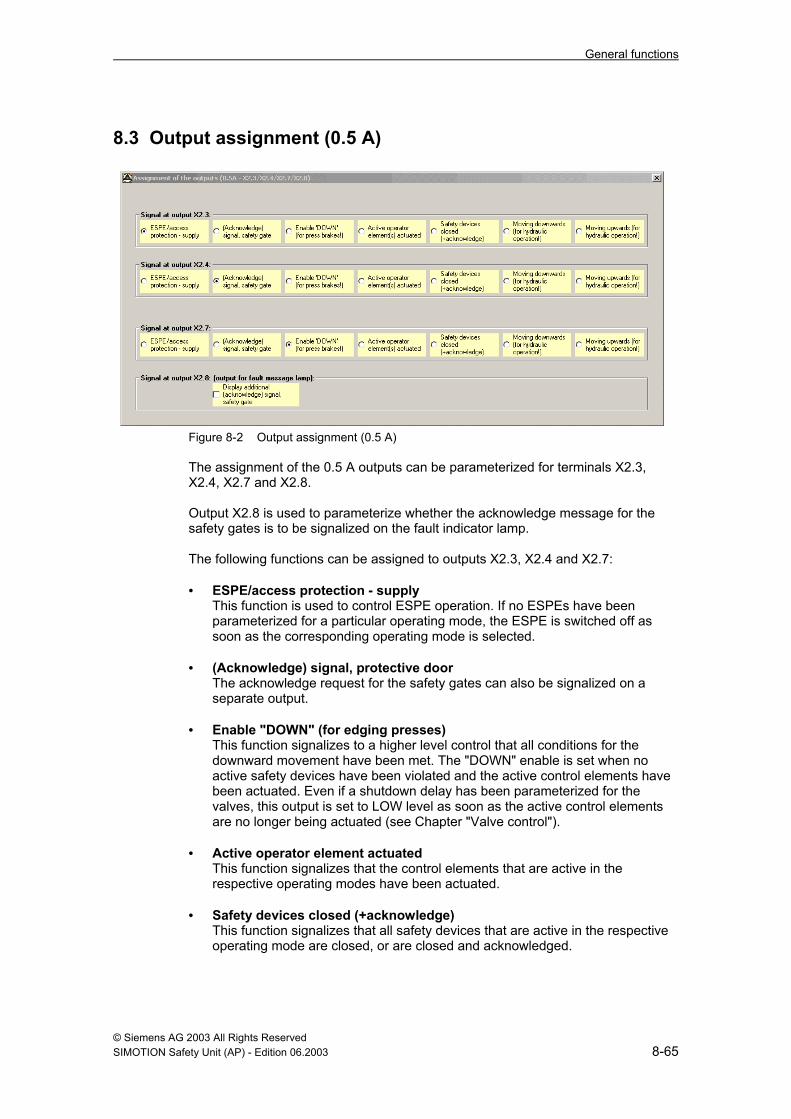
8.3 Output assignment (0.5 A)
Figure 8-2 Output assignment (0.5 A) The assignment of the 0.5 A outputs can be parameterized for terminals X2.3, X2.4, X2.7 and X2.8. Output X2.8 is used to parameterize whether the acknowledge message for the safety gates is to be signalized on the fault indicator lamp. The following functions can be assigned to outputs X2.3, X2.4 and X2.7: • ESPE/access protection - supply
This function is used to control ESPE operation. If no ESPEs have been parameterized for a particular operating mode, the ESPE is switched off as soon as the corresponding operating mode is selected.
• (Acknowledge) signal, protective door
The acknowledge request for the safety gates can also be signalized on a separate output.
• Enable "DOWN" (for edging presses)
This function signalizes to a higher level control that all conditions for the downward movement have been met. The "DOWN" enable is set when no active safety devices have been violated and the active control elements have been actuated. Even if a shutdown delay has been parameterized for the valves, this output is set to LOW level as soon as the active control elements are no longer being actuated (see Chapter "Valve control").
• Active operator element actuated
This function signalizes that the control elements that are active in the respective operating modes have been actuated.
• Safety devices closed (+acknowledge)
This function signalizes that all safety devices that are active in the respective operating mode are closed, or are closed and acknowledged.
General functions
© Siemens AG 2003 All Rights Reserved 8-66 SIMOTION Safety Unit (AP) - Edition 06.2003
• "Moving downwards" (for hydraulic operation!) This function signalizes that the downward movement of the hydraulic press is being performed. This means that the press safety valves and the valves for the downward movement are being controlled.
• "Moving upwards" (for hydraulic operation!)
This function signalizes that the upward movement of the hydraulic press is being performed. This means that the press safety valves and the valves for the upward movement are being controlled.

© Siemens AG 2003 All Rights Reserved SIMOTION Safety Unit (AP) - Edition 06.2003 9-67
9 Operating and fault messages
Table 9-1 System errors
Display Error description Corrective measure
F001 Error in internal CPU RAM See 1) F002 RAM error See 1) F003 EPROM error See 1) F004 Data error in dual port RAM See 1) F005 Data error in memory card or memory card empty See 1) F006 Dissimilar FW versions See 1) F007 Internal synchronization error See 1) F008 Watchdog has responded See 1) F009 Undervoltage error in 5V supply See 1) F010 ODIS signal error See 1) F011 PLD error See 1) F012 Subsystem ID error See 1) F013 Error from plug-in monitor for memory card See 1) F014 Keyswitch error See 1) F015 CPU error See 1) F016 System data error See 1) F017 Program execution error See 1) F018 Application error See 1) F019 Serial interface error See 1) F020 Error, input X4.1 See 2) F021 Error, input X4.2 See 2) F022 Error, input X4.3 See 2) F023 Error, input X4.4 See 2) F024 Error, input X4.5 See 2) F025 Error, input X4.6 See 2) F026 Error, input X4.7 See 2) F027 Error, input X4.8 See 2) F028 Error, input X4.9 See 2) F029 Error, input X4.10 See 2) F030 Error, input X4.11 See 2) F031 Error, input X4.12 See 2) F032 Error, input X4.13 See 2) F033 Error, input X4.14 See 2) F034 Error, input X4.15 See 2) F035 Error, input X4.16 See 2) F036 – F039 Not assigned - F040 Error, input X3.1 See 2) F041 Error, input X3.2 See 2)
9
Operating and fault messages
© Siemens AG 2003 All Rights Reserved 9-68 SIMOTION Safety Unit (AP) - Edition 06.2003
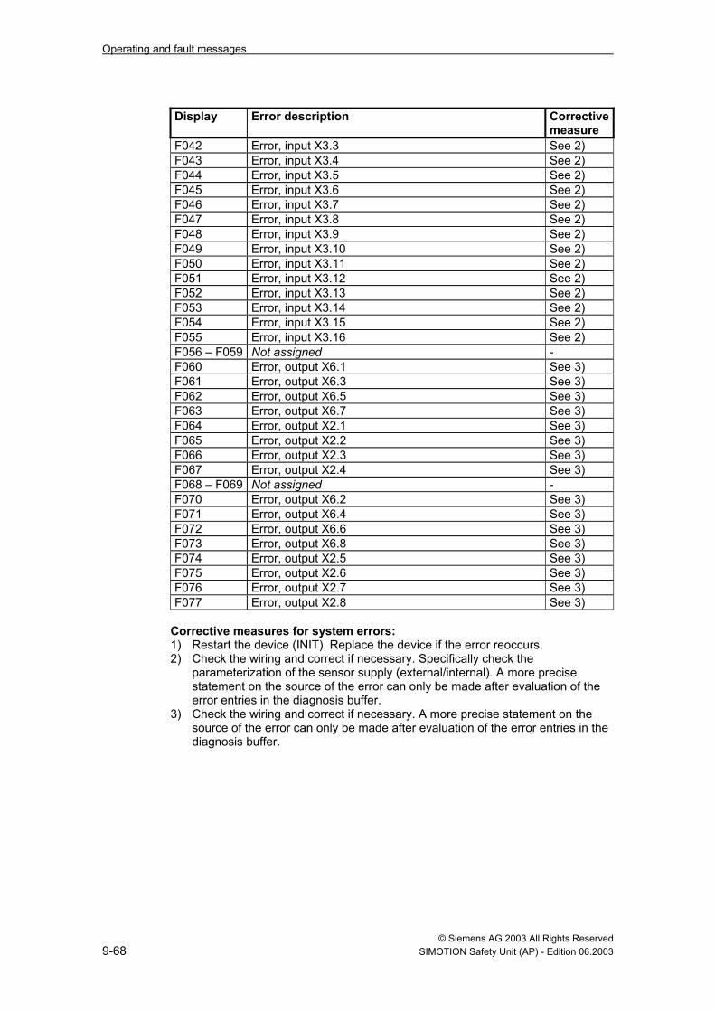
Display Error description Corrective measure
F042 Error, input X3.3 See 2) F043 Error, input X3.4 See 2) F044 Error, input X3.5 See 2) F045 Error, input X3.6 See 2) F046 Error, input X3.7 See 2) F047 Error, input X3.8 See 2) F048 Error, input X3.9 See 2) F049 Error, input X3.10 See 2) F050 Error, input X3.11 See 2) F051 Error, input X3.12 See 2) F052 Error, input X3.13 See 2) F053 Error, input X3.14 See 2) F054 Error, input X3.15 See 2) F055 Error, input X3.16 See 2) F056 – F059 Not assigned - F060 Error, output X6.1 See 3) F061 Error, output X6.3 See 3) F062 Error, output X6.5 See 3) F063 Error, output X6.7 See 3) F064 Error, output X2.1 See 3) F065 Error, output X2.2 See 3) F066 Error, output X2.3 See 3) F067 Error, output X2.4 See 3) F068 – F069 Not assigned - F070 Error, output X6.2 See 3) F071 Error, output X6.4 See 3) F072 Error, output X6.6 See 3) F073 Error, output X6.8 See 3) F074 Error, output X2.5 See 3) F075 Error, output X2.6 See 3) F076 Error, output X2.7 See 3) F077 Error, output X2.8 See 3)
Corrective measures for system errors: 1) Restart the device (INIT). Replace the device if the error reoccurs. 2) Check the wiring and correct if necessary. Specifically check the
parameterization of the sensor supply (external/internal). A more precise statement on the source of the error can only be made after evaluation of the error entries in the diagnosis buffer.
3) Check the wiring and correct if necessary. A more precise statement on the source of the error can only be made after evaluation of the error entries in the diagnosis buffer.

Operating and fault messages
© Siemens AG 2003 All Rights Reserved SIMOTION Safety Unit (AP) - Edition 06.2003 9-69
Table 9-2 Error messages requiring acknowledgement
Display Error description F101 Over run cam static "1" F102 Over run cam failed F103 Over run cam static "0" F104 Overtravel distance to long F105 Ramp up cam failed F106 Operating mode change not in TDC F107 Short circuit at mode selector switch F108 Speed monitor F109 Runtime error, channel 1 (valve 1) F110 Runtime error, channel 2 (valve 2) F111 Runtime error, channel 3 (valve 3) F112 Runtime error, channel 4 (EMERGENCY OFF output signal) F113 Light curtain mode selection (1 cycle/2 cycle) F114 Short circuit or "0" at light curtain mode selector switch F115 Setting - dynamic cam F122 Discrepancy error, transfer point F123 Error in dynamic valve control, channel 1 F124 Error in dynamic valve control, channel 2 F125 Error in dynamic valve control, channel 3 F316 Restart inhibit, EMERGENCY OFF is set F317 Restart inhibit, safety guard is set F318 Restart inhibit, light curtain is set F319 Restart inhibit, EMERGENCY OFF output signal F320 *) Safety gate closed – not ready for acknowledge (blocked) F321 *) Safety gate closed – ready for acknowledge
This error can only be acknowledged in the Setup operating mode *) If the safety gate display is parameterized for the fault lamp.

Operating and fault messages
© Siemens AG 2003 All Rights Reserved 9-70 SIMOTION Safety Unit (AP) - Edition 06.2003
Table 9-3 Self-acknowledging error messages
Display Error description F201 Discrepancy error, EMERGENCY_OFF 1 F202 Discrepancy error, EMERGENCY_OFF 2 F203 Discrepancy error, EMERGENCY_OFF 3 F204 Discrepancy error, EMERGENCY_OFF 4 F205 Discrepancy error, EMERGENCY_OFF 5 F206 Discrepancy error, EMERGENCY_OFF 6 F207 Discrepancy error, EMERGENCY_OFF 7 F208 Discrepancy error, EMERGENCY_OFF 8 F209 Discrepancy error, safety guard 1 F210 Discrepancy error, safety guard 2 F211 Discrepancy error, safety guard 3 F212 Discrepancy error, safety guard 4 F213 Discrepancy error, safety guard 5 F214 Discrepancy error, safety guard 6 F215 Discrepancy error, safety guard 7 F216 Discrepancy error, safety guard 8 F217 Contact error, two-hand 1 F218 Contact error, two-hand 2 F219 Contact error, two-hand 3 F220-F222 Not assigned F223 Discrepancy error, restart inhibit 1 F224 Discrepancy error, restart inhibit 2 F225 Discrepancy error, light curtain F226 Contact error, foot switch 1 F227 Contact error, foot switch 2 F228 Contact error, foot switch 3 F229 Discrepancy error, access protection 1 F230 Discrepancy error, access protection 2 F231 Plug-in control, two-hand 1 F232 Plug-in control, two-hand 2 F233 Plug-in control, two-hand 3 F234 Plug-in control, foot 1 F235 Plug-in control, foot 2 F236 Plug-in control, foot 3 F237 Operating error (two-hand 1 was actuated but is not active) F238 Operating error (two-hand 2 was actuated but is not active) F239 Operating error (two-hand 3 was actuated but is not active) F240 Operating error (foot switch 1 was actuated but is not active) F241 Operating error (foot switch 2 was actuated but is not active) F242 Operating error (foot switch 3 was actuated but is not active)

© Siemens AG 2003 All Rights Reserved SIMOTION Safety Unit (AP) - Edition 06.2003 10-71
10 Documentation
10.1 Documentation of inputs (notes) X3 Pin Description Cable Notes 1 2 3 4 5 6 7 8 9
10 11 12 13 14 15 16 X4 1 2 3 4 5 6 7 8 9
10 11 12 13 14 15 16
10

Documentation
© Siemens AG 2003 All Rights Reserved 10-72 SIMOTION Safety Unit (AP) - Edition 06.2003
10.2 Documentation of outputs (notes) • Outputs 2 A
X6 Pin Description Cable Notes 1 2 3 4 5 6 7 Emergency stop P 8 Emergency stop N
• Outputs 0.5 A X2 Pin Description Cable Notes 1 Output P Cycle 12 Output P Cycle 23 4 5 Output P Cycle 36 Output P Cycle 47 8 Error message
10.3 Documentation of system data The CRC checksum should be entered on the label on the back of the memory card and on the label located on the housing next to the memory card. A complete function text must be performed after changes are made to the parameterization, whether after the equipment is exchanged or after the memory card is replaced (see Chapter 2.2 Device manual).

© Siemens AG 2003 All Rights Reserved SIMOTION Safety Unit (AP) - Edtion 06.2003 73
To SIEMENS AG A&D MC BMS P.O. Box 3180 D-91050 Erlangen Tel. +49 (180) 50 50 222 Fax +49 (9131) 98 2176 E-Mail: [email protected] Return address: Your name: _ _ _ _ _ _ _ _ _ _ _ _ _ _ _ _ _ _ _ _ _ _ _ _ _ _ _ _ _ _ _ _ _ _ _ Your position: _ _ _ _ _ _ _ _ _ _ _ _ _ _ _ _ _ _ _ _ _ _ _ _ _ _ _ _ _ _ _ _ _ _ _ Your company: _ _ _ _ _ _ _ _ _ _ _ _ _ _ _ _ _ _ _ _ _ _ _ _ _ _ _ _ _ _ _ _ _ _ _ Street: _ _ _ _ _ _ _ _ _ _ _ _ _ _ _ _ _ _ _ _ _ _ _ _ _ _ _ _ _ _ _ _ _ _ _ City: _ _ _ _ _ _ _ _ _ _ _ _ _ _ _ _ _ _ _ _ _ _ _ _ _ _ _ _ _ _ _ _ _ _ _ Telephone: _ _ _ _ _ _ _ _ _ _ _ _ _ _ _ _ _ _ _ _ _ _ _ _ _ _ _ _ _ _ _ _ _ _ _ Please put a cross next to your industry sector: ❐ Automotive industry ❐ Pharmaceutical industry ❐ Chemical industry ❐ Plastics processing ❐ Electrical industry ❐ Paper industry ❐ Food industry ❐ Textile industry ❐ Control technology ❐ Transportation ❐ Mechanical engineering ❐ Other _ _ _ _ _ _ _ _ _ _ _ _ _ ❐ Petrochemical industry ❐
© Siemens AG 2003 All Rights Reserved 74 SIMOTION Safety Unit (AP) - Edition 06.2003
Comments/suggestions
Your comments and suggestions assist us in improving the quality and usability of our documentation. Please fill in this questionnaire at the next opportunity and send it back to Siemens. Title of manual: Safety Unit TM 121C Application manual for presses Order no. of manual: 6AU1900-0DM20-0XA0 Please enter your personal assessment on a scale from 1 = good to 5 = poor. 1. Does the contents meet your requirements? □2. Is the required information easy to locate? □3. Are the texts easy to understand? □4. Does the degree of technical detail meet your requirements? □5. How do you rate the quality of the figures and tables? □ If you have encountered any specific problems, please describe them below: _ _ _ _ _ _ _ _ _ _ _ _ _ _ _ _ _ _ _ _ _ _ _ _ _ _ _ _ _ _ _ _ _ _ _ _ _ _ _ _ _ _ _ _ _ _ _ _ _ _ _ _ _ _ _ _ _ _ _ _ _ _ _ _ _ _ _ _ _ _ _ _ _ _ _ _ _ _ _ _ _ _ _ _ _ _ _ _ _ _ _ _ _ _ _ _ _ _ _ _ _ _ _ _ _ _ _ _ _ _ _ _ _ _ _ _ _ _ _ _ _ _ _ _ _ _ _ _ _ _ _ _ _ _ _ _ _ _ _ _ _ _ _ _ _ _ _ _ _ _ _ _ _ _ _ _ _ _ _ _ _ _ _ _ _ _ _ _ _ _ _ _ _ _ _ _ _ _ _ _ _ _ _ _ _ _ _ _ _ _ _ _ _ _ _ _ _ _ _ _ _ _ _ _ _ _ _ _ _ _ _ _ _ _ _ _ _ _ _ _ _ _ _ _ _ _ _ _ _ _ _ _ _ _ _ _ _ _ _ _ _ _ _ _ _ _ _ _ _ _ _ _ _ _ _ _ _ _ _ _ _ _ _ _ _ _ _ _ _ _ _ _ _ _ _ _ _ _ _ _ _ _ _ _ _ _ _ _ _ _ _ _ _ _ _ _ _ _ _ _ _ _ _ _ _ _ _ _ _ _ _ _ _ _ _ _ _ _ _ _ _ _ _ _ _ _ _ _ _ _ _ _ _ _ _ _ _ _ _ _ _ _ _ _ _ _ _ _ _ _ _ _ _ _ _ _ _ _ _ _ _ _ _ _ _ _ _ _ _ _ _ _ _ _ _ _ _ _ _ _ _ _ _ _ _ _ _ _ _ _ _ _ _ _ _ _ _ _ _ _ _ _ _ _ _ _ _ _ _ _ _ _ _ _ _ _ _ _ _ _ _ _ _ _ _ _ _ _ _ _ _ _ _ _ _ _ _ _ _ _ _ _ _ _ _ _ _ _ _ _ _ _ _ _ _ _ _ _ _ _ _ _ _ _ _ _ _ _ _ _ _ _ _ _ _ _ _ _ _ _ _ _ _ _ _ _ _ _ _ _ _ _ _ _ _ _ _ _ _ _ _ _ _ _ _ _ _ _ _ _ _ _ _ _ _ _ _ _ _ _ _ _ _ _ _ _ _ _ _ _ _ _ _ _ _ _ _ _ _ _ _ _ _ _ _ _ _ _ _ _ _ _ _ _ _ _ _ _ _ _ _ _ _ _ _ _ _ _ _ _ _ _ _ _ _ _ _ _ _ _ _ _ _ _ _ _ _ _ _ _ _ _ _ _ _ _ _ _ _ _ _ _ _ _ _ _ _ _ _ _ _ _ _ _ _ _ _ _ _ _ _ _ _ _ _ _ _ _ _ _ _ _ _ _ _ _ _ _ _ _ _ _ _ _ _ _ _ _ _ _ _ _ _ _ _ _ _ _ _ _ _ _ _ _ _ _ _ _ _ _ _ _ _ _ _ _ _ _ _ _ _ _ _ _ _ _ _ _ _ _ _ _ _ _ _ _ _ _ _ _ _ _ _ _ _ _ _ _ _ _ _ _ _ _ _ _ _ _ _ _ _ _ _ _ _ _ _ _ _ _ _ _ _ _ _ _ _ _ _ _ _ _ _ _ _ _ _ _ _ _ _ _ _ _ _ _ _ _ _ _ _ _ _ _ _


Siemens AG Automation and Drives Motion Control Systems P.O. Box 3180, D – 91050 Erlangen Federal Republic of Germany www.ad.siemens.de
© Siemens AG 2003Subject to change without prior notice.
Order no.: 6AU1900-0DM20-0XA0
Printed in the Federal Republic of Germany