simatic pcs 7 application description y july 2013 · existing projects. the “fermenter” unit...
TRANSCRIPT

Applications & Tools
Answers for industry.
Cover
PCS 7 Unit Template “Fermenter” using the example of the Chemical Industry
SIMATIC PCS 7
Application Description July 2013
2 Fermenter
V1.0, Entry ID: 68098270
Cop
yrig
ht
Sie
men
s A
G 2
013
All
right
s re
serv
ed
Siemens Industry Online Support This entry is taken from the Siemens Industry Online Support. The following link takes you directly to the download page of this document: http://support.automation.siemens.com/WW/view/en/68098270 Caution: The functions and solutions described in this article confine themselves to the realization of the automation task predominantly. Please also take into account that corresponding protective measures have to be taken in the context of Industrial Security when connecting your equipment to other parts of the plant, the enterprise network or the Internet. For more information, please refer to Entry ID 50203404. http://support.automation.siemens.com/WW/view/en/50203404

Fermenter V1.0, Entry ID: 68098270 3
Cop
yrig
ht
Sie
men
s A
G 2
013
All
right
s re
serv
ed
s
SIMATIC PCS 7 Fermenter Application Example
Task Description and Solution
1 Fundamentals – Process Engineering
2 Structure and Function Principle
3 Integrating the Unit Template
4 Starting the Unit Template
5
Operating the Application 6
Related Literature 7
History 8

Warranty and Liability
4 Fermenter
V1.0, Entry ID: 68098270
Cop
yrig
ht
Sie
men
s A
G 2
013
All
right
s re
serv
ed
Warranty and Liability
Note The Application Examples are not binding and do not claim to be complete regarding the circuits shown, equipping and any eventuality. The application examples do not represent customer-specific solutions. You are responsible for ensuring that the described products are used correctly. These application examples do not relieve you of your responsibility to use safe practices in application, installation, operation and maintenance. When using these application examples, you recognize that we cannot be made liable for any damage/claims beyond the liability clause described. We reserve the right to make changes to these application examples at any time without prior notice. If there are any deviations between the recommendations provided in this application example and other Siemens publications – e.g. catalogs – the contents of the other documents have priority.
We do not accept any liability for the information contained in this document. Any claims against us – based on whatever legal reason – resulting from the use of the examples, information, programs, engineering and performance data etc., described in this application example will be excluded. Such an exclusion will not apply in the case of mandatory liability, e.g. under the German Product Liability Act (“Produkthaftungsgesetz”), in case of intent, gross negligence, or injury of life, body or health, guarantee for the quality of a product, fraudulent concealment of a deficiency or breach of a condition which goes to the root of the contract (“wesentliche Vertragspflichten”). The damages for a breach of a substantial contractual obligation are, however, limited to the foreseeable damage, typical for the type of contract, except in the event of intent or gross negligence or injury to life, body or health. The above provisions do not imply a change of the burden of proof to your detriment. Any form of duplication or distribution of these application examples or excerpts hereof is prohibited without the expressed consent of Siemens Industry Sector.

Preface
Fermenter V1.0, Entry ID: 68098270 5
Cop
yrig
ht
Sie
men
s A
G 2
013
All
right
s re
serv
ed
Preface Objective of this application
The objective of this application is to supply you with a prefabricated and unified example project for a process engineering plant. It offers a quick introduction and know-how acquisition, based on the appropriate equipment modules. This example project can be adjusted flexibly to your own requirements and be integrated into your own multi-projects.
Main contents The following core points are discussed in this application: Structure of a fermenter Description of the individual functions and configurations Handling the application example
Validity As of SIMATIC PCS 7 V8.0 SP1

Table of Contents
6 Fermenter
V1.0, Entry ID: 68098270
Cop
yrig
ht
Sie
men
s A
G 2
013
All
right
s re
serv
ed
Table of Contents Warranty and Liability .............................................................................................. 4 Preface ...................................................................................................................... 5 Table of Contents ..................................................................................................... 6 1 Task Description and Solution ...................................................................... 8
1.1 Task .................................................................................................. 8 1.2 Solution ............................................................................................. 8 1.2.1 Fermenter unit ................................................................................... 8 1.2.2 Overview of the overall solution ......................................................... 9 1.2.3 Core functionality ............................................................................. 11 1.2.1 Description of the individual functions .............................................. 12 1.2.2 Control concept ............................................................................... 14 1.2.3 P&I flow diagram ............................................................................. 15 1.3 Hardware and software components ................................................ 16
2 Fundamentals – Process Engineering......................................................... 17
2.1 Fermenter ........................................................................................ 17 2.2 Temperature control ........................................................................ 17
3 Structure and Function Principle ................................................................. 18
3.1 Project structure .............................................................................. 18 3.1.1 Naming conventions for CFC charts ................................................. 18 3.1.2 Plant view ........................................................................................ 19 3.2 Equipment modules and process tags.............................................. 20 3.3 Cleaning (CIP) ................................................................................. 21 3.3.1 Structure.......................................................................................... 21 3.3.2 Configuration ................................................................................... 22 3.4 pH value control (pH) ....................................................................... 24 3.4.1 Structure.......................................................................................... 24 3.4.2 Configuration ................................................................................... 25 3.5 Filling level (Level) ........................................................................... 27 3.5.1 Structure.......................................................................................... 27 3.5.2 Configuration ................................................................................... 28 3.5.3 Extension possibilities ...................................................................... 30 3.6 Pressure control (Pressure) ............................................................. 31 3.6.1 Structure.......................................................................................... 31 3.6.2 Configuration ................................................................................... 32 3.6.3 Extension possibilities ...................................................................... 32 3.7 Jacket temperature control (JacketTemp) ........................................ 33 3.7.1 Structure.......................................................................................... 33 3.7.2 Configuration ................................................................................... 34 3.8 Product temperature control (ProductTemp) .................................... 35 3.8.1 Configuration ................................................................................... 36 3.9 Sequential function charts (SFC) ..................................................... 39 3.10 Process simulation (ProcSimulation) ................................................ 44 3.11 Process characteristics (KPI) ........................................................... 45
4 Integrating the Unit Template ...................................................................... 46
4.1 Preparation ...................................................................................... 46 4.2 Implementation ................................................................................ 46
5 Starting the Unit Template ........................................................................... 48
5.1 Preparation ...................................................................................... 48 5.2 Commissioning ................................................................................ 49

Table of Contents
Fermenter V1.0, Entry ID: 68098270 7
Cop
yrig
ht
Sie
men
s A
G 2
013
All
right
s re
serv
ed
6 Operating the Application ............................................................................ 50
6.1 Overview ......................................................................................... 50 6.2 Scenario A ....................................................................................... 50 6.3 Scenario B ....................................................................................... 51
7 Related Literature ......................................................................................... 53
7.1 Bibliography..................................................................................... 53 7.2 Internet links .................................................................................... 53
8 History .......................................................................................................... 54

1 Task Description and Solution 1.1 Task
8 Fermenter
V1.0, Entry ID: 68098270
Cop
yrig
ht
Sie
men
s A
G 2
013
All
right
s re
serv
ed
1 Task Description and Solution 1.1 Task
The standardization of automation technologies in process engineering plants, as in the field of chemical industry, for example, constitutes a major challenge. Various processes and process steps, different accessories, and flexibility in production make this task even more complicated. One approach to solve this problem is a structured plant layout on the basis of a physical model according to DIN EN 61512. In this standard, the lower four levels of the model, i.e. plant, unit, technical facility and individual control unit, are specified in detail. A plant is always made up of units. These units may again include further standardized technical facilities, also referred to as equipment modules.
1.2 Solution
1.2.1 Fermenter unit
This application example refers to the unit of a universal fermenter (bioreactor) for white biotechnology plants which can be integrated in various types of industrial plants. Such fermenters with jacket temperature control and a cleaning option (CIP = Cleaninig In Place) are frequently used in chemical industry. In contrast, fermenters for red biotechnology (production of pharmaceuticals) typically have much smaller volumes and other, specific automation functions. The “Fermenter” unit template offers a model which includes all typical components, ranging from regulation and control over the necessary logistics and interlocking functions up to visualization. Its modular structure is based on standardized equipment modules. The use of this unit template offers the following advantages: requires less know-how about application design and development reduces the time and effort required for configuration offers flexible integration and adaptation through the use of equipment
modules provides uniform structures

1 Task Description and Solution 1.2 Solution
Fermenter V1.0, Entry ID: 68098270 9
Cop
yrig
ht
Sie
men
s A
G 2
013
All
right
s re
serv
ed
1.2.2 Overview of the overall solution
Display The figure below shows a possible specification of a chemical plant for the production of bio-ethanol based on a fermenter.
Figure 1-1: Process layout of a typical chemical plant with a fermenter as a part of the bio-ethanol process
Delivery Storage Mill-ing
Liquefaction Saccharifaction Fermentation Distillation Storage
Drying
Water Enzymes Yeast CO2
Level Flow Pressure Temperature Valve positioning Weighing
Distillation
Dehydration
Separation
Methylation
Bioethanol
Superheated steam
Thin slop
Syrup
DGS
Cooling tower / cooling plant
Fracti-onation
DDGS
Bioethanol
Bioethanol
LoadingDrying
Description The “fermenter” unit template includes several preconfigured, standardized and readily interconnected equipment modules. Based on this sample solution, numerous instances with different parameter settings can be generated and adapted for integration into a variety of automation solutions. The hardware-independent configuration of the PCS 7 project enables flexible integration into existing projects. The “Fermenter” unit template has been realized in the form of a PCS 7 multiproject as follows: The Component View contains one project for the automation system (AS) and
one project for the operator station (OS). The Plant View contains a hierarchy folder for each equipment module of the
fermenter. All control functions are realized in the AS project in the form of CFCs (continuous function charts). Furthermore, the AS project includes a hierarchy folder with simulation charts for simulating processes, for example, a change in filling levels within an equipment module.

1 Task Description and Solution 1.2 Solution
10 Fermenter
V1.0, Entry ID: 68098270
Cop
yrig
ht
Sie
men
s A
G 2
013
All
right
s re
serv
ed
All equipment modules are available in the master data library of the project in the form of process tag types and include function blocks of the PCS 7 Advanced Process Library (APL). The OS project comprises the visualization of the fermenter with all equipment modules and shows: a schematic layout of the fermenter the relevant indicators (KPI: Key Performance Indicators) controlling a cleaning process (CIP) controlling a discontinuous production process
Delimitation The automation solution on hand has been developed for a fermenter in discontinuous operation in the white biotechnology environment. "White biotechnology" refers to industrial manufacturing of products with biotechnological methods. Microorganisms or cells are used here to produce the desired product naturally. Typical target branches are fine chemical industry and food technology. The sample solution is based on fermentation processes for bio-ethanol. Other alcohols (incl. beer) as well as biogas are manufactured in fermenters; however, the plant instrumentation can deviate strongly from the fermenters for bio-ethanol. The aim of "red biotechnology", on the other hand, is to access the genome of microorganisms to produce certain pharmaceuticals or extract DNA sequences and proteins for diagnosis. These are products which the cell would not naturally produce and which are therefore allocated to the pharmaceutical sector. Fermenters in red biotechnology pose special requirements on the automation which are not covered by the sample solutions on hand. A respective so-called “Bioreactor Control Toolbox” is currently developed (see /2/ in related literature in chapter 7). The engineering process within the fermenter is not simulated. With an enhanced simulation, the unit template could also be used in an operator training system.
Required knowledge Basic knowledge of the following subject areas is required: Configuration with PCS 7 and APL Knowledge in the field of control engineering Basic process engineering knowledge

1 Task Description and Solution 1.2 Solution
Fermenter V1.0, Entry ID: 68098270 11
Cop
yrig
ht
Sie
men
s A
G 2
013
All
right
s re
serv
ed
1.2.3 Core functionality
The following chapter describes the individual components of a fermenter. Access takes place via the process image of the visualization user interface. Figure 1-2: R&I scheme of the fermenter in the PCS 7 OS display
Process image The process image of a fermenter comprises the following elements: Schematic illustration of the unit with feed components (arranged on the left of
the reactor) and discharge components (arranged on the right of the fermenter) Faceplates to control the individual components (aggregates) SFC for the production and cleaning process Overview of all relevant indicators (Key Performance Indicators) and operating
duration displays The process image provides an overview of the entire unit and allows the operator to intervene as required.

1 Task Description and Solution 1.2 Solution
12 Fermenter
V1.0, Entry ID: 68098270
Cop
yrig
ht
Sie
men
s A
G 2
013
All
right
s re
serv
ed
1.2.1 Description of the individual functions
Figure 1-3
1
34
5
87
1
2
6
The process image of the fermenter comprises the following main components: 1. Cleaning in place (CIP) without dismantling 2. Inflow of an ingredient 3. pH value control 4. Stirrer 5. Pressure control 6. Temperature control (product and jacket temperature) 7. Reactor 8. Product discharge
(1) Cleaning in place (CIP) The cleaning in place process uses a detergent to perform the cleaning of surfaces in contact with the product (e.g. brine and/or base). Cleaning steps and duration are defined in the SFC and started by the operator on demand (no part of the solution).
(2) Inflow of an ingredient An ingredient (biomass) is added to the tank via the feed until a defined filling level is reached. The flow rate can be adjusted by the operator to the required production volume or vary depending on a preceding process step (mixing of various ingredients). The valve is controlled on demand via SFC.
(3) pH value control Based on the fed ingredient, a pH value specified for the product is regulated by means of a neutralizer, either brine/base or acid. For the pH value control, deviations between setpoint and actual value are controlled by increasing or reducing the inflow of the neutralizer.

1 Task Description and Solution 1.2 Solution
Fermenter V1.0, Entry ID: 68098270 13
Cop
yrig
ht
Sie
men
s A
G 2
013
All
right
s re
serv
ed
(4) Stirrer The motor-driven stirrer is used for mixing the added ingredient with the neutralizer in order to obtain a homogeneous distribution of the material concentration and temperature within the reactor. The stirrer is controlled on demand via SFC.
(5) Pressure control The fermentation process produces a gas mixture (amongst others CO2) which causes a pressure increase within the tank. The pressure can be reduced by opening an outlet valve (continuously adjustable valve), so that the gas mixture can escape from the tank.
(6) Temperature control Temperature control consists of two sections. 1. Temperature control via the tank jacket provides an optimal environment for
the fermentation process. The specified temperature inside jacket of the reactor is obtained by feeding either heating steam/water or cooling water into the tank jacket via supply pipes. The tank jacket influences the temperature within the reactor with a slight time lag.
2. The fermentation process and the neutralization reaction heat the product in the tank. In order to oppose this temperature increase, the product is continuously pumped through a heat exchanger.
(7) Reactor The fermentation takes place inside the reactor. The reactor is designed and selected with consideration of process-specific relationships which may be quite complex in some parts. These include, among others, the following: ingredients (for alternating products) and neutralizers which require a specific
design or tank property feed and discharge quantities and the production volume to determine the
reactor size fermentation and neutralization in the appropriate ambient conditions required
(pH value, temperature and pressure)
(8) Product discharge The product discharge can be controlled in different ways. Either, a ball valve with a given flow rate value is used, or an open/close valve is used which permits the maximum flow rate (depending on the cross-section of the pipe). The valve is controlled on demand via SFC.
Further functions After starting the control, a production process is performed with a cleaning process at the end. After cleaning, all controllers and actuators are enabled for the operator. The operator can start the production on demand or control the individual components of the fermenter.
1 Task Description and Solution 1.2 Solution
14 Fermenter
V1.0, Entry ID: 68098270
Cop
yrig
ht
Sie
men
s A
G 2
013
All
right
s re
serv
ed
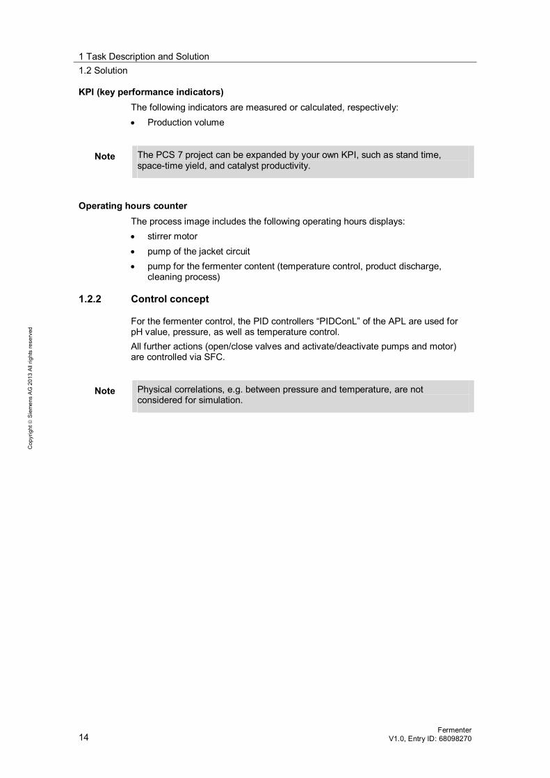
KPI (key performance indicators) The following indicators are measured or calculated, respectively: Production volume
Note The PCS 7 project can be expanded by your own KPI, such as stand time, space-time yield, and catalyst productivity.
Operating hours counter The process image includes the following operating hours displays: stirrer motor pump of the jacket circuit pump for the fermenter content (temperature control, product discharge,
cleaning process)
1.2.2 Control concept
For the fermenter control, the PID controllers “PIDConL” of the APL are used for pH value, pressure, as well as temperature control. All further actions (open/close valves and activate/deactivate pumps and motor) are controlled via SFC.
Note Physical correlations, e.g. between pressure and temperature, are not considered for simulation.

1 Task Description and Solution 1.2 Solution
Fermenter V1.0, Entry ID: 68098270 15
Cop
yrig
ht
Sie
men
s A
G 2
013
All
right
s re
serv
ed
1.2.3 P&I flow diagram
The figure below shows the individual elements of a fermenter in the form of a piping and instrumentation flow diagram.
Figure 1-4
YCJacket_C
TICReactor
YCJacket_H
TICJacket
Hot steam
Cooling water M
NSPumpJacket
Product
LILevel
YCProduct
YCFeed
CIP
Neutralizer
YCClP_In
Feed
PICPressure
Venting
NSMotor
YCOut
YCNeutrSubst
QICpH
CIP
YCCIP_Out
NSPumpReactor
Outflow
Coolant
M
YCCool
YCCooling

1 Task Description and Solution 1.3 Hardware and software components
16 Fermenter
V1.0, Entry ID: 68098270
Cop
yrig
ht
Sie
men
s A
G 2
013
All
right
s re
serv
ed
1.3 Hardware and software components
This application was generated with the following components:
Hardware components Table 1-1
Component Note SIMATIC PCS 7 ES/OS IPC547D W7 For the PCS 7 V8.0 SP1 example project
Note When using different hardware, please observe the minimum requirements for installing the software components. The minimum requirements are available in the PCS 7 readme file.
Standard software components Table 1-2
Component Note SIMATIC PCS 7 V8.0 SP1 Part of SIMATIC PCS 7 ES/OS IPC547D W7 S7-PLCSIM License not part of SIMATIC PCS 7 APL Library V8.0 SP1 Part of in SIMATIC PCS 7 V8.0 SP1
Sample files and projects The following list includes all files and projects that are used in this example. Table 1-3
Component Note 68098270_Fermenter_PCS7V801.zip PCS 7 V8.0 sample project 68098270_Fermenter_en.pdf This document

2 Fundamentals – Process Engineering 2.1 Fermenter
Fermenter V1.0, Entry ID: 68098270 17
Cop
yrig
ht
Sie
men
s A
G 2
013
All
right
s re
serv
ed
2 Fundamentals – Process Engineering 2.1 Fermenter
The term “fermentation” is derived from Latin and refers to the conversion of biological matter aided by bacteria, fungi or cell cultures (animal or plant cells), or enzymes. In the fermentation process, a specific mixing ratio of different raw materials (reactants), or a product from a preceding process, are fed into a fermenter. The actual fermentation process occurs in the fermenter. A defined pH value is set by means of an added neutralizer (acid or base). A heat exchanger and a temperature controlled fermenter jacket are used for regulating the temperature.
2.2 Temperature control
In the fermenter, an optimal environment for producing the fermentation product is required. For this reason, the temperature in the fermenter jacket is adjusted to the temperature required for the manufacturing process. In the course of temperature control, the jacket of the fermenter (double jacket) is either heated up or cooled down for a constant jacket temperature. The transition of heat and the associated time lags depend on the thickness and thermal conductivity of the jacket as well as the inner fermenter wall. In the course of plant operation, the heat transition properties may change due to the formation of deposit layers (“fouling”). Adding a neutralizer causes an exothermal chemical reaction in the fermenter which causes a temperature increase in the mixture. The fermentation process itself also causes release of reaction heat. To balance these changes and for setting a given temperature, the mixture is pumped through a cooling heat exchanger.

3 Structure and Function Principle 3.1 Project structure
18 Fermenter
V1.0, Entry ID: 68098270
Cop
yrig
ht
Sie
men
s A
G 2
013
All
right
s re
serv
ed
3 Structure and Function Principle 3.1 Project structure
3.1.1 Naming conventions for CFC charts
The designation of process tags follows a uniform naming convention, whereby the function is named in compliance with the European standard EN 62424. The figure below shows how a process tag name is composed: Figure 3-1
TIC_Jacket
FunctionT = Temperature (first letter)I = Display (following letter)C = Control (following letter)
Designation
The following table contains all letters used in this application and their meaning: Table 3-1
First letter Meaning
F Flow L Level N Motor P Pressure Q Quantity T Temperature Y Control valve
Table 3-2
Next letter Meaning
C Control I Indication F Fraction S Binary control function or switching function (not
safety-relevant) (Switching)
3 Structure and Function Principle 3.1 Project structure
Fermenter V1.0, Entry ID: 68098270 19
Cop
yrig
ht
Sie
men
s A
G 2
013
All
right
s re
serv
ed
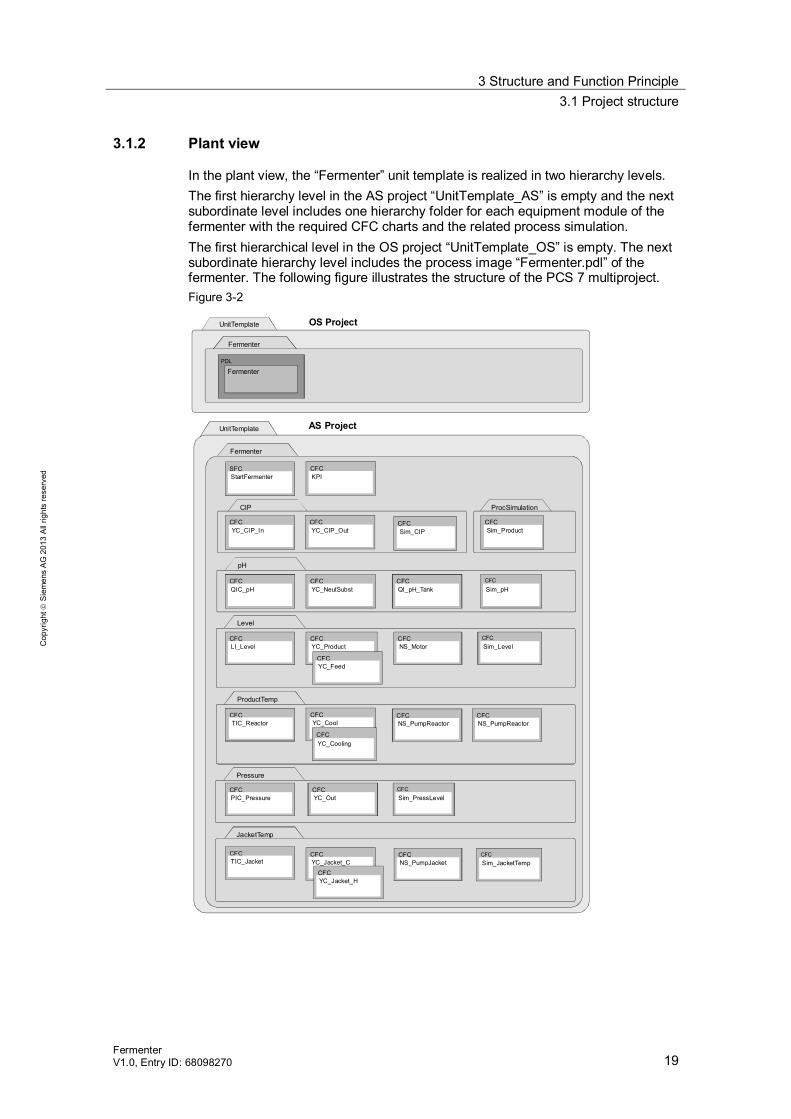
3.1.2 Plant view
In the plant view, the “Fermenter” unit template is realized in two hierarchy levels. The first hierarchy level in the AS project “UnitTemplate_AS” is empty and the next subordinate level includes one hierarchy folder for each equipment module of the fermenter with the required CFC charts and the related process simulation. The first hierarchical level in the OS project “UnitTemplate_OS” is empty. The next subordinate hierarchy level includes the process image “Fermenter.pdl” of the fermenter. The following figure illustrates the structure of the PCS 7 multiproject. Figure 3-2
UnitTemplate
UnitTemplate
Fermenter
Fermenter
FermenterPDL
AS Project
OS Project
Level
CFCLI_Level
CFCYC_Product
CFCSim_Level
Pressure
CFCPIC_Pressure
CFCSim_PressLevel
CFCYC_Out
JacketTemp
CFCSim_JacketTemp
CFCYC_Jacket_C
CFCTIC_Jacket
CFCNS_PumpJacket
SFCStartFermenter
ProductTemp
CFCNS_Motor
pH
CFCQIC_pH
CFCYC_NeutSubst
CFCSim_pH
CFCTIC_Reactor
CFCYC_Cool
CIP
CFCYC_CIP_In
CFCYC_CIP_Out
CFCYC_Cooling
CFCNS_PumpReactor
CFCYC_Jacket_H
CFCQI_pH_Tank
CFCNS_PumpReactor
ProcSimulation
CFCSim_Product
CFCYC_Feed
CFCKPI
CFCSim_CIP

3 Structure and Function Principle 3.2 Equipment modules and process tags
20 Fermenter
V1.0, Entry ID: 68098270
Cop
yrig
ht
Sie
men
s A
G 2
013
All
right
s re
serv
ed
3.2 Equipment modules and process tags
The “Fermenter” unit template is composed of preconfigured equipment modules and additional process tags, for example, for process simulation. In the PCS 7 project, all process tags, as well as the process tags of the equipment modules are based on process tag types from the master data library. The application description “Equipment Modules Using the Example of the Chemical Industry” and the sample projects including the individual equipment modules and process tag types are available under the entry ID: 53843373. The fermenter application example includes the following components: Cleaning in place (CIP): detergent inflow and outflow pH value control (pH): controlling the acid content of the product Filling level (Level): ingredient inflow and drainage of the product after the
fermentation process and stirring the product Pressure control (Pressure): regulation of the tank pressure Jacket temperature control (JacketTemp): regulation of the jacket temperature Product temperature control (ProductTemp): regulation of the product
temperature Sequencer (SFC) for a production Comprehensive process simulation (ProcSimulation) Key performance indicators (KPI)
The following subchapters explain the structure of the individual equipment modules, as well as the expansions of and changes to the equipment modules and process tag types used. Furthermore, the SFC for reactor start-up is described.
Note All necessary descriptions, configurations and procedures for the reference versions are available in the documentation with the entry ID: 53843373. For further information on individual equipment modules, please refer to chapter 5 “Equipment Modules” and the process tag types in chapter 4 “Process Tag Types”.

3 Structure and Function Principle 3.3 Cleaning (CIP)
Fermenter V1.0, Entry ID: 68098270 21
Cop
yrig
ht
Sie
men
s A
G 2
013
All
right
s re
serv
ed
3.3 Cleaning (CIP)
Tank cleaning is realized by adding a detergent. Process tag type “Val_An_Afb1” of the master data library is used for detergent inflow and drainage and controlled via SFC.
3.3.1 Structure
Opening and closing the valves is performed via the SFC “CLEANING”. The table below provides an overview of the individual elements and the process tag types used.
Table 3-3
Designation Process tag type Description
YC_CIP_In “Val_An_Afb1” Control valve for detergent inflow YC_CIP_Out “Val_An_Afb1” Control valve for detergent outflow
The following figure shows a simplified illustration of the structure of the feed inflow, including any interconnections or SFC access across different CFC charts.
Figure 3-3
Sim_CIP
IN_CIPIn1
SFCYC_CIP_In
VMV
V
CIP_Flow_SumOut
YC_CIP_Out
VMV
V
OpenAutCloseAutModLiOp
AutModLiManModLi
OpenAut
CloseAutModLiOp
AutModLiManModLi
OUT_CIPIn1
3 Structure and Function Principle 3.3 Cleaning (CIP)
22 Fermenter
V1.0, Entry ID: 68098270
Cop
yrig
ht
Sie
men
s A
G 2
013
All
right
s re
serv
ed
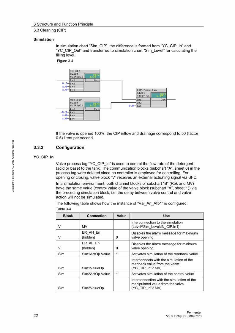
Simulation In simulation chart “Sim_CIP”, the difference is formed from “YC_CIP_In” and “YC_CIP_Out” and transferred to simulation chart “Sim_Level” for calculating the filling level. Figure 3-4
If the valve is opened 100%, the CIP inflow and drainage correspond to 50 (factor 0.5) liters per second.
3.3.2 Configuration
YC_CIP_In Valve process tag “YC_CIP_In” is used to control the flow rate of the detergent (acid or base) to the tank. The communication blocks (subchart “A”, sheet 6) in the process tag were deleted since no controller is employed for controlling. For opening or closing, valve block “V” receives an external actuating signal via SFC. In a simulation environment, both channel blocks of subchart “B” (Rbk and MV) have the same value (control value of the valve block (subchart “A”, sheet 1)) via the preceding simulation block; i.e. the delay between valve control and valve action will not be simulated. The following table shows how the instance of “Val_An_Afb1” is configured. Table 3-4
Block Connection Value Use
V MV Interconnection to the simulation (Level\\Sim_Level\IN_CIP.In1)
V ER_AH_En (hidden) 0
Disables the alarm message for maximum valve opening
V ER_AL_En (hidden) 0
Disables the alarm message for minimum valve opening
Sim Sim1ActOp.Value 1 Activates simulation of the readback value
Sim Sim1ValueOp
Interconnects with the simulation of the readback value from the valve (YC_CIP_In\V.MV)
Sim Sim2ActOp.Value 1 Activates simulation of the control value
Sim Sim2ValueOp
Interconnection with the simulation of the manipulated value from the valve (YC_CIP_In\V.MV)

3 Structure and Function Principle 3.3 Cleaning (CIP)
Fermenter V1.0, Entry ID: 68098270 23
Cop
yrig
ht
Sie
men
s A
G 2
013
All
right
s re
serv
ed
YC_CIP_Out The valve process tag “YC_CIP_Out” is used to control the detergent drainage from the tank. The communication blocks (subchart “A”, sheet 6) in the process tag are not required since no controller is employed for controlling. For opening or closing, valve block “V” receives an external actuating signal via SFC. In a simulation environment, both channel blocks of subchart “B” (Rbk and MV) have the same value (control value of the valve block (subchart “A”, sheet 1)) via the preceding simulation block; i.e. the delay between valve control and valve action will not be simulated. The following table shows how the instance of “Val_An_Afb1” is configured. Table 3-5
Block Connection Value Use
V MV Interconnection to the simulation (Level\\Sim_Level\IOUT_CIP.In1)
V ER_AH_En (hidden) 0
Disables the alarm message for maximum valve opening
V ER_AL_En (hidden) 0
Disables the alarm message for minimum valve opening
Sim Sim1ActOp.Value 1 Activates simulation of the readback value
Sim Sim1ValueOp
Interconnects with the simulation of the readback value from the valve (YC_CIP_Out\V.MV)
Sim Sim2ActOp.Value 1 Activates simulation of the control value
Sim Sim2ValueOp
Interconnection with the simulation of the manipulated value from the valve (YC_CIP_Out\V.MV)

3 Structure and Function Principle 3.4 pH value control (pH)
24 Fermenter
V1.0, Entry ID: 68098270
Cop
yrig
ht
Sie
men
s A
G 2
013
All
right
s re
serv
ed
3.4 pH value control (pH)
pH level control is realized by means of equipment module “pH-Control-Std”. This equipment module realizes a non-linear pH value control taking into consideration the titration profile. Most of the fermenters are operated at constant pH value (beneficial to the microorganisms used) and not subjected to sudden disturbances of the pH value. For most of the fermenters, a linear control of the pH value is sufficient without knowing the titration profile. Instead of the equipment module “pH-Control-Std”, the more simple equipment module “Level-Control” can then be used for pH value control.
Note The flow rate control with equipment module “Level-Control” contains an integrated behavior. Change the simulation before applying for pH value control.
In the simulation chart, all influencing variables (inflow, drainage) are acquired across all process tags and taken into account for forming the pH value.
3.4.1 Structure
The PID controller captures the pH value from the simulation chart and controls by adding neutralizer depending on the specified pH value. The table below provides an overview of the individual elements.
Table 3-6
Designation Equipment module / process tag type
Description
QIC_pH “pH-Control-Std” pH value control via the concentration difference YC_NeutrSubst “pH-Control-Std” Control valve for the inflow of the neutralizer QI_pH_Tank “pH-Control-Std” Display process tag of the pH value
Note A description and further information on the configuration and principle of the equipment module “pH-Control-Std” is available in chapter 5 “Equipment Modules” of the documentation which is available at entry ID: 53843373.
Simulation CFC chart “Sim_pH” (part of the equipment module “pH” of the Fermenter unit template) calculates the pH value in the reactor based on the inflow (ingredient and neutralizer).

3 Structure and Function Principle 3.4 pH value control (pH)
Fermenter V1.0, Entry ID: 68098270 25
Cop
yrig
ht
Sie
men
s A
G 2
013
All
right
s re
serv
ed
Figure 3-5
1
24
3
(1) + (2) The simulation is based on the “SimpHTitr” simulation block of
equipment module “pH-Control-Std” and was expanded by integrators for discontinuous operation.
(3) + (4) additional blocks for resetting the simulation values Figure 3-6
5
6
Creating (5) a slight noise and adding (6) it to the process value
3.4.2 Configuration
QIC_pH The configuration of this process tag deviates from pH value control “pH-Control-Std” as follows: Table 3-7
Block Connection Value Use
C Gain 190 Controller gain C TI 720 Controller delay
pH_SP
Interconnection deleted, block renamed and moved to sheet 6. Additionally, a conversion block (pH -> Mol/L) was added and interconnected with the display block

3 Structure and Function Principle 3.4 pH value control (pH)
26 Fermenter
V1.0, Entry ID: 68098270
Cop
yrig
ht
Sie
men
s A
G 2
013
All
right
s re
serv
ed
Note Controller optimization for the “pH-Control-Level” process tag has already been performed with the PID tuner. The controller is optimized for a fast neutralization process. For a slow (homogenous) neutralization process you change the controller parameter (Gain = 41, TI = 300) accordingly. A description for performing the controller optimization is available in chapter 6 “Equipment Modules” of the documentation which is available under the entry ID: 53843373 and in the article “How do you do a controller optimization with the PCS 7 PID Tuner?” under the entry ID: 8031495.
Note To specify the value (internal setpoint value) in non-production mode of operation, you can use the converted pH value from the “pH_Mol_per_Liter” faceplate in the OS. Alternatively you can insert an additional OpAnL block in CFC “QIC_pH” chart and interconnect it with the Connector.SP_Ext input. The specified setpoint occurs in the “operator control and monitoring” block of the OS. In this case, the controller for the automatic mode must be set with the external setpoint value.
YC_NeutrSubst The configuration of this process tag deviates from pH value control “pH-Control-Std” as follows: Table 3-8
Block Connection Value Use
V MV
Interconnection to the simulation (Sim_ProductTemp\Temp_Incr_Neutr.In1) (Sim_Level\Neutr_Scale.In1)
QI_pH_Tank The configuration of this process tag does not deviate from pH value control “pH-Control-Std”.

3 Structure and Function Principle 3.5 Filling level (Level)
Fermenter V1.0, Entry ID: 68098270 27
Cop
yrig
ht
Sie
men
s A
G 2
013
All
right
s re
serv
ed
3.5 Filling level (Level)
Filling level control in batch operation (“dosing control”) is not performed with an equipment module with continuous control, but with a process tag type from the master data library. The control commands are handled via SFC sequence chains which control the ingredient inflow, mixing, and the product outflow. Preparation and mixing of the ingredient (various musts, yeast) is performed in a preceding unit. Therefore, the inflow in this example consists of one ingredient (preliminary product). The filling level is calculated in the simulation chart.
3.5.1 Structure
The filling level in the product is controlled via SFC. The respective valves and the stirrer motor are opened/closed and started/stopped via the respective valves. In the simulation chart, any inflow is recorded and the filling level is output in the display process tag as a percentage. The table below provides an overview of the individual elements.
Table 3-9
Designation Equipment module / process tag type
Description
LI_Level “AMON__Std” Display of the measured filling level as a percentage
YC_Product “Val_An_Afb1” Control valve for product discharge (drainage) YC_Feed “Val_An_Afb1” Control valve for the preliminary product (inflow) NS_Motor “MOT_1sp_1fb_1cm__Std” Stirrer motor for homogenous mixing
Note Detailed information on the individual SFC sequence chains is available in chapter 3.9 “Sequential function charts (SFC)”.
Figure 3-7
Sim_Level
Feed_ScaleIn1
SFC YC_Feed
VMV
V
Level_Max_PercenOut
LI_Level
I
OpenAut
CloseAut
ModLiOp
AutModLi
ManModLi
Sim1ActOp
YC_Product
VMV
VOpenAut
CloseAut
ModLiOp
AutModLi
ManModLi
Outflow_ScaleIn1
NS_Motor
UFbkRunOut
UStartAut
StopAut
ModLiOpAutModLi
ManModLi

3 Structure and Function Principle 3.5 Filling level (Level)
28 Fermenter
V1.0, Entry ID: 68098270
Cop
yrig
ht
Sie
men
s A
G 2
013
All
right
s re
serv
ed
Simulation “Sim_Level” In the simulation chart, the filling level is calculated from the total of any inflow and the drainage converted as a percentage.
Figure 3-8
1
2 4
5
6 73
1. Inflow of the ingredient (100 % valve opening correspond to 20 l/s) with a delay of 1 second (PT1 behavior)
2. Inflow of the neutralizer (100 % valve opening correspond to 1 l/s) with a delay of 1 second (PT1 behavior)
3. Drainage of the product (100 % valve opening correspond to 20 l/s) 4. Summarizing any inflow and drainage including CIP and forming an integral
value 5. Creating a noise signal as of a filling level of 30% 6. Adding the noise signal to the filling level 7. Converting the filling level from liters into percent (100% filling level correspond
to 4000 liters)
3.5.2 Configuration
LI_Level The “LI_Level” display process tag uses the filling level percentage of the “Sim_Level” simulation for the process value display. The following table shows the configuration of the instance from “AMON__Std”. Table 3-10
Block Connection Value Use
Sim Sim1ActOp.Value 1 Activates simulation
Sim Sim1ValueOp
Interconnection to the simulated process value (Sim_Level\Level_Max_Percen.Out)
PV Scale 100 Maximum value of the process value
PV PV_InUnit 1342 Unit of the process value as a percentage

3 Structure and Function Principle 3.5 Filling level (Level)
Fermenter V1.0, Entry ID: 68098270 29
Cop
yrig
ht
Sie
men
s A
G 2
013
All
right
s re
serv
ed
YC_Product The “YC_Product” valve process tag controls the product flow rate (opening drain valve) from the tank. The communication blocks (subchart “A”, sheet 6) in the process tag were deleted since no controller is employed for controlling. For opening or closing, valve block “V” receives an external actuating signal via SFC. In a simulation environment, both channel blocks of subchart “B” (Rbk and MV) have the same value (control value of the valve block (subchart “A”, sheet 1)) via the preceding simulation block; i.e. the delay between valve control and valve action will not be simulated. The following table shows how the instance of “Val_An_Afb1” is configured. Table 3-11
Block Connection Value Use
V MV Interconnection to the simulation (Sim_Level\Outflow_Scale.In1)
V ER_AH_En (hidden) 0
Disables the alarm message for maximum valve opening
V ER_AL_En (hidden) 0
Disables the alarm message for minimum valve opening
from_CTRL Block deleted to_CTRL Block deleted
Sim Sim1ActOp.Value 1 Activates simulation of the readback value
Sim Sim1ValueOp
Interconnects with the simulation of the readback value from the valve (YC_Product\V.MV)
Sim Sim2ActOp.Value 1 Activates simulation of the control value
Sim Sim2ValueOp
Interconnection with the simulation of the manipulated value from the valve (YC_Product\V.MV)
YC_Feed The valve process tag “YC_Feed” is used to control the ingredient flow rate (by opening the feed valve) to the tank. The communication blocks (subchart “A”, sheet 6) in the process tag were deleted since no controller is employed for controlling. For opening or closing, valve block “V” receives an external actuating signal via SFC. In a simulation environment, both channel blocks of subchart “B” (Rbk and MV) have the same value (control value of the valve block (subchart “A”, sheet 1)) via the preceding simulation block; i.e. the delay between valve control and valve action will not be simulated. The following table shows how the instance of “Val_An_Afb1” is configured. Table 3-12
Block Connection Value Use
V MV Interconnection to the simulation (Sim_Level\Feed_Scale.In1)
V ER_AH_En (hidden) 0
Disables the alarm message for maximum valve opening

3 Structure and Function Principle 3.5 Filling level (Level)
30 Fermenter
V1.0, Entry ID: 68098270
Cop
yrig
ht
Sie
men
s A
G 2
013
All
right
s re
serv
ed
Block Connection Value Use
V ER_AL_En (hidden) 0
Disables the alarm message for minimum valve opening
V MV_HiLim 60.0 Limiting the manipulated variable (max. inflow)
from_CTRL Block deleted to_CTRL Block deleted
Sim Sim1ActOp.Value 1 Activates simulation of the readback value
Sim Sim1ValueOp
Interconnects with the simulation of the readback value from the valve (YC_Feed\V.MV)
Sim Sim2ActOp.Value 1 Activates simulation of the control value
Sim Sim2ValueOp
Interconnecting with the simulation of the manipulated value from the valve (YC_Feed\V.MV)
NS_Motor The stirrer mixes the ingredient with the neutralizer in the reactor. Stirrer control is performed via SFC and based on process tag type “MOT_1sp_1fb_1cm__Std”. This process tag type is included in the master data library and it is used for motors driven at constant speed. Configuring the instance from “MOT_1sp_1fb_1cm__Std” was not necessary.
Note A description and further information on the configuration and principle of the process tag type “MOT_1sp_1fb_1cm__Std” can be found in chapter 4 “Control Modules” of the documentation which is available under the entry ID: 53843373.
Note The “Limit” block of the APL can be used for interlocking the motor, e.g. when falling short of the filling level, and be connected to the interlock block of the motor process tag. In this case, the stirrer interlock becomes active when falling short of a defined filling level of the reactor and the motor cannot be started.
3.5.3 Extension possibilities
Filling level acquisition For tanks, additional measures for protecting the plant can be taken irrespective of the control concept. This includes, for example, a filling level switch which opens a drain valve upon contact with the medium, and subsequently drains the tank contents. Some filling level switches (Pointek CSL200) can forward their signals to the automating system where a message is displayed in the OS on demand.

3 Structure and Function Principle 3.6 Pressure control (Pressure)
Fermenter V1.0, Entry ID: 68098270 31
Cop
yrig
ht
Sie
men
s A
G 2
013
All
right
s re
serv
ed
3.6 Pressure control (Pressure)
Pressure control is realized by means of the “Level-Control” equipment module. Using the pressure control, surplus pressure ( 8 mbar) is released from the tank during the neutralization (fermentation) process. Pressure calculation is effected in the simulation chart.
3.6.1 Structure
The PID controller detects the tank pressure from the simulation chart and reduces the pressure (venting). The table below provides an overview of the individual elements.
Table 3-13
Designation Equipment module / process tag type
Description
PIC_Pressure “Level Control” Pressure control of a tank YC_Out “Level Control” Control valve for venting
Note The description, configuration, and procedure for equipment module “Level-Control” is available in chapter 5 “Equipment Modules” of the documentation at entry ID: 53843373.
Simulation Sim_PressLevel CFC chart “Sim_PressLevel” (which is part of the “Split-Range-Pressure” equipment module) receives the manipulated variable of the venting valve (negative value). The control valve for the inert gas was substituted by adding two disturbance values. The figure below shows the structure and process of simulation. Figure 3-9
1
In the Diff “block” (1), the fermentation volume (pressure change due to the fermentation process) and the filling level-related inflow (pressure change due to different filling levels) is recorded in addition to the manipulated venting variable.
3 Structure and Function Principle 3.6 Pressure control (Pressure)
32 Fermenter
V1.0, Entry ID: 68098270
Cop
yrig
ht
Sie
men
s A
G 2
013
All
right
s re
serv
ed
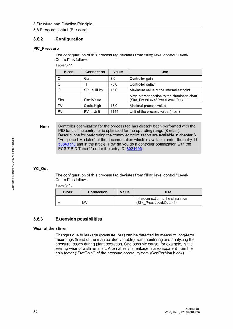
3.6.2 Configuration
PIC_Pressure The configuration of this process tag deviates from filling level control “Level-Control” as follows: Table 3-14
Block Connection Value Use
C Gain 8.0 Controller gain C TI 75.0 Controller delay C SP_InHiLim 15.0 Maximum value of the internal setpoint
Sim Sim1Value New interconnection to the simulation chart (Sim_PressLevel\PressLevel.Out)
PV Scale.High 15.0 Maximal process value PV PV_InUnit 1138 Unit of the process value (mbar)
Note Controller optimization for the process tag has already been performed with the PID tuner. The controller is optimized for the operating range (8 mbar). Descriptions for performing the controller optimization are available in chapter 6 “Equipment Modules” of the documentation which is available under the entry ID: 53843373 and in the article “How do you do a controller optimization with the PCS 7 PID Tuner?” under the entry ID: 8031495.
YC_Out The configuration of this process tag deviates from filling level control “Level-Control” as follows: Table 3-15
Block Connection Value Use
V MV Interconnection to the simulation (Sim_PressLevel\Out.In1)
3.6.3 Extension possibilities
Wear at the stirrer Changes due to leakage (pressure loss) can be detected by means of long-term recordings (trend of the manipulated variable) from monitoring and analyzing the pressure losses during plant operation. One possible cause, for example, is the sealing wear of a stirrer shaft. Alternatively, a leakage is also apparent from the gain factor (“StatGain”) of the pressure control system (ConPerMon block).

3 Structure and Function Principle 3.7 Jacket temperature control (JacketTemp)
Fermenter V1.0, Entry ID: 68098270 33
Cop
yrig
ht
Sie
men
s A
G 2
013
All
right
s re
serv
ed
3.7 Jacket temperature control (JacketTemp)
Temperature control of the fermenter jacket is realized by means of the “Split-Range-Temperature” equipment module. In addition, the process tag type “MOT_1sp_1fb_1cm__Std” is used to pump over the jacket liquid. The temperature calculation is effected in the simulation chart.
3.7.1 Structure
The PID controller records the temperature of the fermenter jacket and increases or reduces the jacket temperature by means of hot steam or cooling water according to the specified temperature. The table below provides an overview of all components.
Table 3-16
Designation Equipment module / process tag type
Description
TIC_Jacket “Split-Range-Temperature” Slave controller for split-range control with one manipulated variable and two actuators
YC_Heat “Split-Range-Temperature” Control valve for heating steam YC_Cool “Split-Range-Temperature” Control valve for cooling water NS_PumpJacket “MOT_1sp_1fb_1cm__Std” Pump (e.g. stream pump) for continuous
circulation of the jacket liquid
Note The display process tags and the process tag for master controller “TIC_Reactor” of the “Split-Range-Temperature” equipment module are not required and are therefore not part of this solution. Therefore, the communication blocks “to_Master” and “from_Master” are deleted in the “TIC_Jacket” controller process tag. The missing process tags and interconnections will not affect the proper function and are not described separately.
Simulation Sim_JacketTemp CFC chart “Sim_JacketTemp” (which is part of equipment module “Split-Range-Temperature”) was reduced by the simulation part of the heat exchanger (“TempLevel” block) and contains an additional disturbance signal. The figure below shows the structure and process of simulation.

3 Structure and Function Principle 3.7 Jacket temperature control (JacketTemp)
34 Fermenter
V1.0, Entry ID: 68098270
Cop
yrig
ht
Sie
men
s A
G 2
013
All
right
s re
serv
ed
Figure 3-10
1
2
1. Creating a noise signal (process behavior) 2. Adding the noise signal to the temperature value of the reactor jacket and
environment-related temperature drop (0.001 degrees Celsius)
NS_PumpJacket The pump is controlled in the CFC “NS_PumpJacket” on the basis of the process tag type “MOT_1sp_1fb_1cm__Std”. This process tag type is part of the master data library.
Note A description and further information on the configuration and principle of the process tag type “MOT_1sp_1fb_1cm__Std” can be found in chapter 4 “Control Modules” of the documentation which is available under the entry ID: 53843373.
Note For the following cases, a pump interlock can be performed (configured):
for switched off controller
detecting a leakage in the jacket
3.7.2 Configuration
Temperature control via the reactor jacket is configured for independent operation. Since, in this example, the system is not influenced by other plant units and the controllers react very quickly, no further modifications are required.

3 Structure and Function Principle 3.8 Product temperature control (ProductTemp)
Fermenter V1.0, Entry ID: 68098270 35
Cop
yrig
ht
Sie
men
s A
G 2
013
All
right
s re
serv
ed
3.8 Product temperature control (ProductTemp)
Temperature control is used for cooling the product temperature. During the fermentation and neutralization process, the product heats by means of exothermal reaction energy. In order to oppose this temperature change, the product is pumped through a heat exchanger and cooled. For realizing the temperature control, the process tag types of the master data library were used. The temperature calculation is effected in the simulation chart. The setpoint value for the inflow rate is given to the PID controller and controlled via the control valve. The table below provides an overview of the individual elements and the process tag types used.
Table 3-17
Designation Process tag type Description
TIC_Reactor “CTRL_ Std4Valve” Controller for the product temperature YC_Cool “Val_An_Afb1” Control valve for the cooling water/agent for heat exchange YC_Cooling “Val_An_Afb1” Control valve for inflow to the heat exchanger NS_PumpReactor “MOT_1sp_1fb_1cm
__Std” Pump (e.g. stream pump) for pumping the reactor content through the heat exchanger and to the product outlet (“YC_Product” valve)
In the following figure the entire structure of the product temperature control, including all interconnections across all CFC charts, are represented in a simplified format.
Figure 3-11
Sim_ProductTemp
Temp_HeatExchangIn1
TIC_Reactor
SimSim1ValueOp
to_ValveOut
from_ValveIn
YC_Cool
VMV
from_CTRLIn
to_CTRLOut
Temp_OutOut
SFCYC_Cooling
VOpenAut
CloseAutModLiOpAutModLi
ManModLi
NS_PumpReactor
UStartAutStopAut
ModLiOpAutModLiManModLi
The controller process tag “TIC_ Reactor” captures the product temperature (simulation chart “Sim_ProductTemp”) and controls it with the help of the control valve “YC_Cool”.

3 Structure and Function Principle 3.8 Product temperature control (ProductTemp)
36 Fermenter
V1.0, Entry ID: 68098270
Cop
yrig
ht
Sie
men
s A
G 2
013
All
right
s re
serv
ed
Simulation In the simulation chart, the product temperature is calculated based on the flow rate of the neutralizer, the flow rate of cooling water to the heat exchanger, and the influence from jacket temperature control.
Figure 3-12
1
2
4
56
3
1. Temperature rise by adding the neutralizer (100 % valve opening corresponds to 0.02°C/s positive temperature change) with a delay of 3 seconds (PT1 behavior)
2. Temperature drop of the product due to inflow of the cooling water into the heat exchanger (100 % valve opening corresponds to 0.1°C/s negative temperature change) with a delay of 3 seconds (PT1 behavior)
3. Adding up all influences on the temperature (neutralization process, heat exchanger, influence from jacket temperature, and resetting the temperature change)
4. Integrating all influences on the temperature 5. Adding the temperature change to the ingredient temperature of 20°C 6. For under 20°C, resetting the temperature change (activated by SFC)
3.8.1 Configuration
TIC_Reactor The following table shows the configuration of the instance from the “CTRL_ Std4Valve” process tag type. Table 3-18
Block Connection Value Use
C NegGain.Value 1 Negative controller gain C Gain.Value 8.5 Controller gain C TI.Value 4 Controller delay C SP_InHiLim 100.0 Maximum value of the internal setpoint C PropFacSP 0.8 Applying the P-action to the feedback
Intlock InvIn02 1 Inverts the hardware error signal from the valve process tag
Intlock InvIn03 1 Inverts the “out of service” signal from the valve process tag
to_Valve Out Interconnection to the valve (control) (YC_Cool\from_CTRL.In)

3 Structure and Function Principle 3.8 Product temperature control (ProductTemp)
Fermenter V1.0, Entry ID: 68098270 37
Cop
yrig
ht
Sie
men
s A
G 2
013
All
right
s re
serv
ed
Block Connection Value Use
from_Valve In
Interconnection to the valve (status and readback) (YC_Cool\to_CTRL.Out)
Sim Sim1ActOp.Value 1 Activating the simulation value
Sim Sim1ValueOp
Interconnection to the simulated process value (Sim_ProductTemp\Temp_Out.Out)
PV Scale 100.0 Maximum value of the process value
PV PV_InUnit 1001 Unit of the process value (degree Centigrade)
Note Controller optimization for the process tag “TIC_Reactor” already performed with the PID tuner. Descriptions for performing the controller optimization are available in chapter 6 “Equipment Modules” of the documentation which is available under the entry ID: 53843373 and in the article “How do you do a controller optimization with the PCS 7 PID Tuner?” under the entry ID: 8031495.
YC_Cool The valve process tag “YC_Cool” controls the flow rate (opening feed valve) of the cooling water to the heat exchanger. The process tag includes communication blocks for data exchange (control signals and control commands) with the controller process tag. The valve block “V” includes an external control value (via a communication block) from the controller process tag. In a simulation environment, both channel blocks of subchart “B” (Rbk and MV) have the same value (control value of the valve block (subchart “A”, sheet 1)) via the preceding simulation block; i.e. the delay between valve control and valve action will not be simulated. The following table shows how the instance of “Val_An_Afb1” is configured. Table 3-19
Block Connection Value Use
V MV Interconnecting to the simulation (Sim_ProductTemp\Temp_HeadExchang.In1)
V ER_AH_En (hidden) 0
Disables the alarm message for maximum valve opening
V ER_AL_En (hidden) 0
Disables the alarm message for minimum valve opening
from_CTRL In Interconnection to the controller (TIC_Reactor\to_Valve.Out)
to_CTRL Out Interconnection to the controller (TIC_Reactor\from_Valve.In)
Sim Sim1ActOp.Value 1 Activates simulation of the readback value
Sim Sim1ValueOp
Interconnecting with the simulation of the readback value from the valve (YC_Cool\V.MV)
Sim Sim2ActOp.Value 1 Activates simulation of the control value

3 Structure and Function Principle 3.8 Product temperature control (ProductTemp)
38 Fermenter
V1.0, Entry ID: 68098270
Cop
yrig
ht
Sie
men
s A
G 2
013
All
right
s re
serv
ed
Block Connection Value Use
Sim Sim2ValueOp
Interconnecting with the simulation of the manipulated value from the valve (YC_Cool\V.MV)
YC_Cooling The valve process tag “YC_Cooling” controls the flow rate (opening feed valve) of the product through the heat exchanger.
Note An alternative is using an on/off valve. In this case, a new process tag must be configured for an on/off valve
The communication blocks (subchart “A”, sheet 6) in the process tag were deleted since no controller is employed for controlling. For opening or closing, valve block “V” receives an external actuating signal via SFC. In a simulation environment, both channel blocks of subchart “B” (Rbk and MV) have the same value (control value of the valve block (subchart “A”, sheet 1)) via the preceding simulation block; i.e. the delay between valve control and valve action will not be simulated. The following table shows how the instance of “Val_An_Afb1” is configured. Table 3-20
Block Connection Value Use
V ER_AH_En (hidden) 0
Disables the alarm message for max. valve opening
V ER_AL_En (hidden) 0
Disables the alarm message for min. valve opening
from_CTRL Block deleted to_CTRL Block deleted Sim Sim1ActOp.Value 1 Activates simulation of the readback value
Sim Sim1ValueOp
Interconnects with the simulation of the readback value from the valve (YC_Feed\V.MV)
Sim Sim2ActOp.Value 1 Activates simulation of the control value
Sim Sim2ValueOp
Interconnecting with the simulation of the manipulated value from the valve (YC_Feed\V.MV)
NS_PumpReactor The pump is used for pumping the product through the heat exchanger, as well as for pumping the product out. The pump is controlled via SFC and based on process tag type “MOT_1sp_1fb_1cm__Std”. This process tag type is included in the master data library and it is used for motors/pumps driven at constant speed. Configuring the instance from “MOT_1sp_1fb_1cm__Std” was not necessary.
Note A description and further information on the configuration and principle of the process tag type “MOT_1sp_1fb_1cm__Std” can be found in chapter 4 “Control Modules” of the documentation which is available under the entry ID: 53843373.

3 Structure and Function Principle 3.9 Sequential function charts (SFC)
Fermenter V1.0, Entry ID: 68098270 39
Cop
yrig
ht
Sie
men
s A
G 2
013
All
right
s re
serv
ed
3.9 Sequential function charts (SFC)
The fermenter was designed for discontinuous operation. The sequencers perform plant startup and shutdown automatically for the plant operator including the production of the fermentation product and the cleaning process. After processing, the plant is in an empty and cleaned state. With the help of SFCs, different behaviors and control strategies can be realized. In the example project, an SFC with four sequence chains has been configured. The SFC “StartFermenter” is configured for automatic production and subsequent cleaning without user interaction. If the SFC is stopped or aborted, the unit will be brought into non-production mode. The SFC includes the following sequences which are described in a simplified form below: ABORTINGSTOPPING PREPARING PRODUCTION CLEANING
The SFCs can be considered as reference points and are adapted to the simulation behavior. For application in real plants, the sequence chains must be modified, if necessary.
Note The parameter assignment for the selection of setpoints and operating modes, including the schematic illustrations, are taken from the function manual “SIMATIC Process Control System PCS 7 PCS 7 Advanced Process Library V8.0”. This function manual is available under the entry ID 57265842 and includes information on operating modes and setpoint selection, as well as further detailed information about all parameters of the APL blocks.
Create and use SFC types, SFC instances for recurring sequences. Continuing information on SFC configuration and on creating SFC types is available in the programming and operating manual “SIMATIC Process Control System PCS 7 SFC for SIMATIC S7” at entry ID: 57265603 and in operating manual “SIMATIC Process Control System SIMATIC PCS 7 Compendium Part C – Equipment Modules with SFC Types” at entry ID: 63187297.
PREPARING When starting the fermenter, the “PREPARING” sequence will be executed to bring the unit into a non-production mode of operation. For this reason, all valves and controllers are prepared for automatic mode with specified SFC value. Then, any inflow is stopped and the fermenter is drained via the CIP outflow. Additionally, the process simulation is reset. The flowchart below shows a simplified scheme of all sequential steps and transitions of the SFC operations. Selection of the operating mode and the type of default setpoint are not considered.

3 Structure and Function Principle 3.9 Sequential function charts (SFC)
40 Fermenter
V1.0, Entry ID: 68098270
Cop
yrig
ht
Sie
men
s A
G 2
013
All
right
s re
serv
ed
Figure 3-13
Product outlet closedFeeds closed
Start
Filling level 0.0
no
yes
EndO
pera
ting
mod
e sw
itch
for a
ll va
lves
,m
otor
s/pu
mps
and
cotn
rolle
rs
CIP outlet open
CIP outlet closed
Dra
inag
e
PRODUCTION The “PRODUCTION” sequence is followed by the “PREPARING” sequence and comprises the discontinuous fermentation process. For the production (batch), the unit is filled with an ingredient at plant shutdown (no production). The valve of the ingredient is opened until a defined filling level has been reached. Neutralizing is performed after filling and during the fermentation process. The pH value controller controls the addition of the neutralizer using the pH value in the tank. Drainage is performed after neutralization has been completed. All controllers obtain the setpoint values relevant for the production process, such as temperature (reactor jacket and product temperature), tank pressure and pH value, from the sequencer. The sequence of steps includes some further queries so the devices (pump and stirrer) for the production process will only start after a filling level of, for example, 20 % has been reached and the pressure controllers have been activated. After the production has been completed (drainage), the process simulation is reset. The flowchart below shows a simplified scheme of all sequential steps and transitions of the SFC operations.

3 Structure and Function Principle 3.9 Sequential function charts (SFC)
Fermenter V1.0, Entry ID: 68098270 41
Cop
yrig
ht
Sie
men
s A
G 2
013
All
right
s re
serv
ed
Figure 3-14
Start
Ingredient inlet openpH setpoint = 7.0
Jacket temperature = 21.0
Temperature 20.0Filling level 20.0
no
yes
Stirrer (motor) active Pump for jacket temp. control active
Jacket pressure = 8.0Product temperature = 21.0
Pump for jacket temp. control active
Stirrer activepH 6.9* 7.1
Temperature 20.0* 22.0Press. 10.0
no
yes
End
Inle
t ope
n,
tem
pera
ture
cont
rol
Mot
or, p
umps
act
ive,
pre
ssur
e,
tem
pera
ture
and
pH
valu
e co
ntro
l act
ive
Filling level 49.0
no
Ingredient inlet closedpH value control
Product outlet open and pump activeController for product temperature locked
Filling level 20.0
no
Stirrer (motor) inactiveController for pH value and pressure locked
Filling level = 0.0
no
Product outlet closed, pump inactive and simulation reset
Mot
or, p
umps
inac
tive
pres
sure
, tem
pera
ture
and
pH
valu
e co
ntro
l ina
ctiv
e
Filli
ngFe
rmen
tatio
nDr
aina
ge

3 Structure and Function Principle 3.9 Sequential function charts (SFC)
42 Fermenter
V1.0, Entry ID: 68098270
Cop
yrig
ht
Sie
men
s A
G 2
013
All
right
s re
serv
ed
CLEANING In the “CLEANING” sequence chain the cleaning of the tank interior is performed by rinsing with a detergent. A lower jacket temperature is set, the “YC_CIP_Out” drain valve is closed and the feed valve “YC_CIP_In” is opened until a defined reactor filling level has been reached. The detergent liquid is stirred in the tank for a given period of time and pumped through the heat exchanger. Afterwards, the liquid is pumped out via the “YC_CIP_Out” valve. All controllers, valves and pumps are enabled for the operator and the simulation is reset.
Note The cleaning process was shortened for this example so none of the multiple rinsing (detergent and water) typical for the process, possibly with a specific resting time, is performed.
The flowchart below shows a simplified scheme of all sequential steps and transitions of the SFC operations. Figure 3-15
Jacket temperature = 9.0
Start
yes
End
Tem
pera
ture
cont
rol,
CIP
valv
es,
CIP outlet closed and simulation reset
Prep
arat
ion
and
fillin
gno
CIP intlet closedRührer und Pumpe aktiv
valve for heat exchanger open cleaning duration = 1 min
Temperature 9.5
CIP intlet open
no
Filling level 70.0
yes
yes
Stirrer and pump inactiveWait time (resting time) = 10 s
CIP outlet open
Tem
pera
ture
con
trol
, CIP
val
ves,
pum
ps a
nd m
otor
s
Clea
ning
and
dra
inag
e
no
Filling level = 0.0

3 Structure and Function Principle 3.9 Sequential function charts (SFC)
Fermenter V1.0, Entry ID: 68098270 43
Cop
yrig
ht
Sie
men
s A
G 2
013
All
right
s re
serv
ed
ABORTINGSTOPPING In the “ABORTINGSTOPPING” sequence chain, all controllers, valves and motors/pumps of the fermenter are stopped and enabled for the operator. Additionally, the process simulation is reset. In the same way as after the cleaning process, the operator has the option to operate all plant units as follows: controlling all of the valves controlling the motor and both pumps changing the setpoint specification (internal setpoint) of the controllers and
monitoring the process performing controller optimization (changing individual controller parameters or
using the PID tuners)
Note The simulation values for the pH value are based on the respective totals of ingredient and neutralizer. After emptying the tank, these values are not reset automatically but only after a renewed SFC run.

3 Structure and Function Principle 3.10 Process simulation (ProcSimulation)
44 Fermenter
V1.0, Entry ID: 68098270
Cop
yrig
ht
Sie
men
s A
G 2
013
All
right
s re
serv
ed
3.10 Process simulation (ProcSimulation)
CFC chart “Sim_Product” contains simulation influences across the individual equipment modules of the fermenter. The simulation influences are described below.
Temperature influence of the jacket temperature on the product temperature Figure 3-16
12
3
1. Comparison of jacket temperature and product temperature 2. Jacket temperature larger than product temperature The product
temperature is increased by 0.001 degree Celsius. 3. Jacket temperature smaller than product temperature The product
temperature is reduced by 0.001 degree Celsius.
Filling level dependent pressure change Figure 3-17
1 2
1. Pressure change (disturbance variable) resulting from a changed filling level.
Depending on the filling level of the fermenter, the pressure is increased (IncrValue) or decreased (DecrValue) in 10 steps over a defined period of time (IncrHold and DecrHold).
2. Standard pressure change of 0.01 mbar, with positive or negative gain due to filling level change (1).
Pressure change due to fermentation process Figure 3-18
Delayed transfer of the ingredient inflow (corresponds to 0.12 mbar at 60% valve opening) to simulation chart “Sim_PressLevel” of the pressure control.
3 Structure and Function Principle 3.11 Process characteristics (KPI)
Fermenter V1.0, Entry ID: 68098270 45
Cop
yrig
ht
Sie
men
s A
G 2
013
All
right
s re
serv
ed
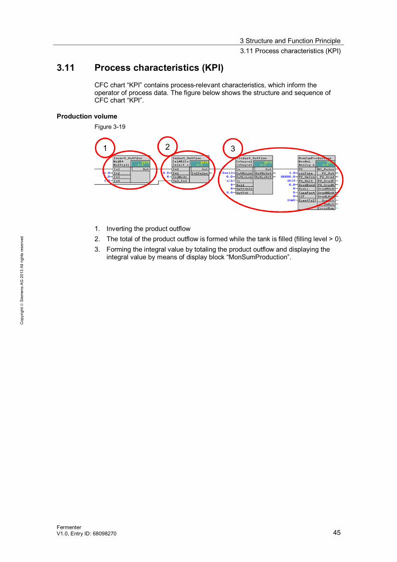
3.11 Process characteristics (KPI)
CFC chart “KPI” contains process-relevant characteristics, which inform the operator of process data. The figure below shows the structure and sequence of CFC chart “KPI”.
Production volume Figure 3-19
1 2 3
1. Inverting the product outflow 2. The total of the product outflow is formed while the tank is filled (filling level > 0). 3. Forming the integral value by totaling the product outflow and displaying the
integral value by means of display block “MonSumProduction”.

4 Integrating the Unit Template 4.1 Preparation
46 Fermenter
V1.0, Entry ID: 68098270
Cop
yrig
ht
Sie
men
s A
G 2
013
All
right
s re
serv
ed
4 Integrating the Unit Template 4.1 Preparation
The following instructions describe how the unit template can be integrated in a PCS 7 project by completing the following steps: Adjustment of HW-Config Configuration of the communication between AS and OS (NetPro) Adaptation of the hierarchy folders Use of a consistent master data library
Note In order to use the example project in your own project, the function blocks “Titr_pH”, “TitrDeltaC” and “TitrLimDeltaC” must be copied for pH value conversion. Additionally, an update of the attributes must be performed when copying the functions and function blocks.
Table 4-1
No. Action
1. Copy the file “68098270_Fermenter_PCS7V801.zip” to the configuration computer and then open the SIMATIC Manager.
2. Select “File > Retrieve” in the menu bar and select the file “68098270_Fermenter_PCS7V801.zip”. Then click “Open” to confirm your selection.
3. Select the folder where the project is saved and confirm with OK. The project will be extracted.
4. In the “Retrieve” dialog, click the “OK” button and then “Yes” to open the project. 5. Change over to “Plant View” 6. Simultaneously, open the project where the fermenter shall be integrated.
4.2 Implementation
The following instructions describe how you can integrate the unit template into your project. Not described are the interconnection of each individual signal and the settings for each individual parameter. The unit template and the target project must be open in the plant view.
Table 4-2
No. Action
1. Open the plant view of the fermenter, select the hierarchy folder “Fermenter” in the AS project and click “Edit > Copy”.
2. Change over to the target project. In the AS project, select the hierarchy folder where the fermenter shall be added, then select “Edit > Paste” from the menu bar. Note All charts including interconnections and simulations will be copied.
3. In the target project, select the AS project and select “Options > Plant View > Update in the Multiproject” from the menu bar. A dialog for the export of the Plant hierarchy opens.

4 Integrating the Unit Template 4.2 Implementation
Fermenter V1.0, Entry ID: 68098270 47
Cop
yrig
ht
Sie
men
s A
G 2
013
All
right
s re
serv
ed
No. Action
4. Click “OK” in this dialog and also confirm the next dialog with “OK”. The Plant hierarchy in the OS project of the target project will be matched accordingly.
5. Compile and download the AS project and then compile the OS project.
Note You may use the process image of the reactor from the sample project. This project is available at < ProjectPath>\UT_Ferm\Ferm_OS\wincproj\OS\GraCS\Fermenter.Pdl>.
In chapter 6 of the application description “Equipment Modules for PC7 Using the Example of the Chemical Industry” under the entry ID 53843373 you will find detailed instructions and notes on the following subjects: Integration of equipment modules
– Adjusting the parameters of an equipment module – Interconnecting an equipment module – Integrating a color palette into the OS
Note Please take note of the modified project path when integrating the color palette in the OS. The project path valid for the “stirred tank reactor” unit template is <ProjectPath>\UT_Ferm\Ferm_OS\wincproj\OS\GraCS\UnitTemplates.xml>.
Process connection Configuration of the PID controllers

5 Starting the Unit Template 5.1 Preparation
48 Fermenter
V1.0, Entry ID: 68098270
Cop
yrig
ht
Sie
men
s A
G 2
013
All
right
s re
serv
ed
5 Starting the Unit Template 5.1 Preparation
The following instructions describe how the unit template can be started by simulating the controller with the “S7-PLCSIM” program. If a real controller is used, the relevant hardware components must be configured in HW-Config.
Table 5-1
No. Action
1. Copy the “68098270_Fermenter_PCS7V801.zip” file to any folder on the configuration computer and then open the SIMATIC Manager.
2. Select “File > Retrieve” in the menu bar and select the file “68098270_Fermenter_PCS7V801.zip”. Then click “Open” to confirm your selection.
3. Select a folder where the project shall be saved and confirm with OK. The project will be retrieved.
4. In the “Retrieve” dialog, click the “OK” button and then “Yes” to open the project. 5. Click the “UnitTemplate_OS > SVE20E > WinCC Appl. > OS” with your right mouse button
and then select the menu command “Open object”. 6. Confirm the dialog “The configured server is not available” with “OK”. 7. Use the WinCC Explorer and open the properties window for your computer; click on the “Use
local computer name” button in the Computer properties dialog. Confirm the “Change computer name” prompt with “OK”.
8. Click “File > Exit” to close the WinCC Explorer and select “Close project and exit WinCC
Explorer” in the next dialog. Then click “OK” to confirm.
9. Open the WinCC Explorer again as described in step 5. 10. Double-click to open the “Tag Management”. In the WinCC Configuration Studio, right-click on
“Tag Management > SIMATIC S7 Protocol Suite > Industrial Ethernet” and select the menu command “System parameters”.
11. Use the “Unit” tab to check the defined “Logical device name”. When using the “S7-PLCSIM” program, the device name PLCSIM(ISO) will be selected. If the device name has been changed, the program must be restarted. Open the WinCC Explorer again as described in step 5. Note If the OS cannot create a connection with the AS (grayed faceplates), select the logic device name “CP_H1_1:” and restart the OS.

5 Starting the Unit Template 5.2 Commissioning
Fermenter V1.0, Entry ID: 68098270 49
Cop
yrig
ht
Sie
men
s A
G 2
013
All
right
s re
serv
ed
5.2 Commissioning
The following instructions describe how the unit template “fermenter” can be set to initialization mode. Initialization requires that the SIMATIC Manager has been opened and the project has been selected in the components view.
Starting simulation (S7-PLCSIM) To start the simulation, proceed as follows:
Table 5-2
No. Action
1. Select “Options > Simulate Modules” from the menu. The dialog window of “S7-PLCSIM” opens.
2. Open the “Open project” dialog and select the option “Open project from file”. 3. Select the file “Fermenter.plc” from the path
<ProjectPath>\UT_Ferm\Ferm_AS\Fermenter.plc >. 4. Select “Execute > Key switch position > RUN-P” from the menu. 5. Change over to the components view of the SIMATIC Manager and select “UnitTemplate_AS
> AS01”. 6. Click “PLC” >”Download” in the menu bar and confirm the “Download” dialog with “Yes”.
Confirm the “Stop Target Module” dialog with “OK” and then the “Download” dialog with “Yes”.
Activating the OS (WinCC Runtime) To activate the OS, proceed as follows:
Table 5-3
No. Action
1. Click the “UnitTemplate_OS > SVE20E > WinCC Appl. > OS” with your right mouse button and then select the menu command “Open object”.
2. Select “File > Activate from the WinCC Explorer menu to activate the OS (WinCC Runtime). 3. In the “System Login” dialog, enter “Unit” as user name and “Template” as password and then
confirm with “OK”. 4. In the picture section, select the unit template “Fermenter”.
Note The fermenter is already in the production/cleaning process, since the AS program processing (PLCSIM) has already been started.

6 Operating the Application 6.1 Overview
50 Fermenter
V1.0, Entry ID: 68098270
Cop
yrig
ht
Sie
men
s A
G 2
013
All
right
s re
serv
ed
6 Operating the Application 6.1 Overview
All components of the fermenter can be operated and monitored via the process image, as well as a production and cleaning process (CIP) be started. The following two scenarios relate to the mode of operation with the “Fermenter” unit template. Scenario A: SFC start with changed parameters Scenario B: working in non-production mode
6.2 Scenario A
Description After activating the OS, the fermenter is either in the production/cleaning process or has already completed this process. The operator can decide between the following options:
Operating the motor, the actuators, pumps and controllers (cleaning completed)
Interrupting/stopping the production or cleaning process in the “Manual” mode of the SFC, and pressing the “Stop” or “Cancel” buttons
Restarting the production with cleaning at the end by pressing the “Start” button
The following scenario explains how to handle the SFC and change the production volume (filling level) from 49 to 39 ( 49% corresponds to approx. 2000 liters, 39 correspond to approx. 1600 liters).
Table 6-1
No. Action
1. Go to “Plant View” and click on the hierarchy folder “Fermenter_MP > UnitTemplate_AS > Fermenter”. The contents of the folder are displayed in the right window pane.
2. Double-click to open the SFC “StartFermenter”.
3. The SFC description in chapter 3.9 tells us that the filling level is polled in sequence chain
“PRODUCTION” (Transition).

6 Operating the Application 6.3 Scenario B
Fermenter V1.0, Entry ID: 68098270 51
Cop
yrig
ht
Sie
men
s A
G 2
013
All
right
s re
serv
ed
No. Action
4. In the SFC you select the “PRODUCTION” sequence chain and enter the new filling level “39” in the “Condition” tab of the object properties of the “Filling_Complete” (Transition) query. Click on the “Accept” button and close the Properties window of the condition.
5. Compile and load the AS user program via menu item “PLC > Download …”.
Note Perform a delta download without parameter readback.
6. Go to the OS and monitor the renewed production process. Notice In the OS, the production is performed with the new filling level. In the SFC, the original filling level is still displayed. To update the SFC display, the OS must be recompiled.
Note The scope of the necessary SFC adjustments increases depending on the change request. If you wish to change the pressure, for example, you need to enter the new setpoint value in the step of the setpoint specification and adjust the step enabling condition in the subsequent (polling) transition.
6.3 Scenario B
This scenario discusses running the plant in non-production mode. In this mode you have the option to operate the individual components of the fermenter and perform a controller optimization, for example. In the following scenario, a production ( 30%) is performed without specific temperature and pressure control with a pH value of 5 pH. All required changes (valves and controller) are made by the operator.

6 Operating the Application 6.3 Scenario B
52 Fermenter
V1.0, Entry ID: 68098270
Cop
yrig
ht
Sie
men
s A
G 2
013
All
right
s re
serv
ed
Table 6-2
No. Action
1. Go to the OS and wait until the production and cleaning process has been terminated or terminate SFC processing by pressing the “Stop” or “Abort” button in “MANUAL” mode.
2. Click on the block icon of the valve of the ingredient, “YC_Feed”, and change the command in the
faceplate to “Open”. 3. Watch the filling level of the tank and close the valve for the ingredient, “YC_Feed”, after reaching
the filling level of approximately 30 %. 4. Use the conversion block to calculate the concentration difference of 5 pH. 5. Click on the block icon of the “QIC_pH” and change the operating mode of the controller to
“Automatic” in the faceplate. 6. Click on the “Setpoint” input field and enter the calculated concentration difference “-208.0” into
the input field of the expansion and click on the “OK” button.
Note The controller of the pH value control is active and reacts to a pH value smaller than 5 pH.
7. After controlling the pH value, the controller reacts to the process changes, e.g: by reopening the valve for the ingredient, “YC_Feed”.
Note In order to obtain a precise pH value, the simulation must be reset prior to a renewed filling. In the SFC you press the “Stop” or “Abort” button or restart a production and cleaning process.

7 Related Literature
Fermenter V1.0, Entry ID: 68098270 53
Cop
yrig
ht
Sie
men
s A
G 2
013
All
right
s re
serv
ed
7 Related Literature 7.1 Bibliography
This list is not complete and only represents a selection of relevant literature. Table 7-1
Topic Title /1/ Practice book for SIMATIC S7 and
SIMATIC PCS7 control systems Controlling with SIMATC Müller, Jürgen / Pfeiffer, Bernd-Markus / Wieser, Roland Publicis Kommunikationsag ISBN 978-3895783401
/2/ Fermenter in red biotechnology Pfeiffer, B-M., Grieb, H., Rougoor, J.: PLS-Toolbox zur Automatisierung von Bioreaktoren. (PLS Toolbox for automation of bioreactors) VDI-Kongress Automation 2011, Baden-Baden. VDI-Berichte 2143, S. 217-221, VDI-Verlag, Düsseldorf.
7.2 Internet links
The following list is not complete and only represents a selection of relevant information. Table 7-2
Topic Title \1\ Link to this document http://support.automation.siemens.com/WW/view/en/
68098270
\2\ Siemens Industry Online Support
http://support.automation.siemens.com
\3\ Controller Optimization with the PID Tuner
http://support.automation.siemens.com/WW/view/en/8031495
\4\ SIMATIC PCS 7 Overview (link collection on FAQ, manuals, compendium, forum, application examples and multimedia)
http://support.automation.siemens.com/WW/view/en/63481413
\5\ Equipment Modules for PCS7 using the example of the Chemical Industry
http://support.automation.siemens.com/WW/view/en/53843373
\6\ PCS 7 Unit Template “Stirred Tank Reactor” using the example of the Chemical Industry
http://support.automation.siemens.com/WW/view/en/60546560
\7\ PCS 7 Unit Template “Distillation Column” using the example of the Chemical Industry
http://support.automation.siemens.com/WW/view/en/48418663
\8\ PCS 7 V8.0 SP1 Manual Collection
http://support.automation.siemens.com/WW/view/en/71178283

8 History
54 Fermenter
V1.0, Entry ID: 68098270
Cop
yrig
ht
Sie
men
s A
G 2
013
All
right
s re
serv
ed
8 History Table 8-1
Version Date Modifications
V1.0 07/2013 First version