signature of band inversion in the antiferromagnetic phase
TRANSCRIPT

PHYSICAL REVIEW RESEARCH 2, 033342 (2020)
Signature of band inversion in the antiferromagnetic phase of axion insulator candidate EuIn2As2
Takafumi Sato ,1,2,3,* Zhiwei Wang,4,* Daichi Takane,1 Seigo Souma ,2,3 Chaoxi Cui,4 Yongkai Li,4 Kosuke Nakayama ,1,5
Tappei Kawakami,1 Yuya Kubota,1 Cephise Cacho,6 Timur K. Kim ,6 Arian Arab,7 Vladimir N. Strocov,7
Yugui Yao,4,† and Takashi Takahashi1,2,3,‡
1Department of Physics, Tohoku University, Sendai 980-8578, Japan2Center for Spintronics Research Network, Tohoku University, Sendai 980-8577, Japan
3WPI Research Center, Advanced Institute for Materials Research, Tohoku University, Sendai 980-8577, Japan4Key Lab of Advanced Optoelectronic Quantum Architecture and Measurement (Ministry of Education), Beijing Key Lab of Nanophotonics,
and Ultrafine Optoelectronic Systems, and School of Physics, Beijing Institute of Technology, 100081 Beijing, China5Precursory Research for Embryonic Science and Technology (PRESTO), Japan Science and Technology Agency (JST),
Tokyo 102-0076, Japan6Diamond Light Source, Harwell Science and Innovation Campus, Didcot, Oxfordshire OX11 0QX, United Kingdom
7Swiss Light Source, Paul Scherrer Institut, CH-5232 Villigen, Switzerland
(Received 22 February 2020; accepted 2 July 2020; published 1 September 2020)
We have performed angle-resolved photoemission spectroscopy on EuIn2As2 which is predicted to be an axioninsulator in the antiferromagnetic state. By utilizing soft-x-ray and vacuum-ultraviolet photons, we revealeda three-dimensional hole pocket centered at the � point of the bulk Brillouin zone together with a heavilyhole-doped surface state in the paramagnetic phase. Upon entering the antiferromagnetic phase, the bandstructure exhibits a marked reconstruction characterized by the emergence of an “M”-shaped bulk band near theFermi level. The qualitative agreement with first-principles band-structure calculations suggests the occurrenceof bulk-band inversion at the � point in the antiferromagnetic phase. We suggest that EuIn2As2 provides a goodopportunity to study the exotic quantum phases associated with a possible axion-insulator phase.
DOI: 10.1103/PhysRevResearch.2.033342
I. INTRODUCTION
The interplay between magnetism and topology is nowbecoming an exciting topic in condensed-matter physics.Magnetic order that spontaneously breaks the time-reversalsymmetry induces various exotic quantum phenomena whichare originally absent in time-reversal-invariant Z2 topologicalinsulators (TIs), as represented by the quantum anomalousHall effect in magnetically doped TIs [1–6], the unusualelectron dynamics in axion TIs [7,8], and the chiral Majoranafermions in superconductor hybrids [9,10]. A well-knownstrategy to realize such fascinating topological phases is theintroduction of magnetic impurities into TI crystals or fab-rication of heterostructures. However, the former inevitablyintroduces disorder in the crystal and the latter requires com-plex steps to achieve desired quantum properties. Thus, therealization of intrinsic magnetic TIs where the magnetic orderis inherently incorporated into the crystal is highly desired,because it would be a more promising platform to realize“cleaner” topological quantum effects.
*These authors contributed equally to this work.†Corresponding author: [email protected]‡Corresponding author: [email protected]
Published by the American Physical Society under the terms of theCreative Commons Attribution 4.0 International license. Furtherdistribution of this work must maintain attribution to the author(s)and the published article’s title, journal citation, and DOI.
Among various magnetic topological materials, the ax-ion insulator is currently attracting particular attention sinceit is predicted to host a topological magnetoelectric ef-fect associated with a hypothetical quasiparticle called anaxion. While the axion insulator was proposed to be re-alized in various systems such as heterostructures involv-ing quantum anomalous Hall insulators [11,12] and mag-netically doped TIs [8,13], the experimental investigationof axion insulators with stoichiometric intrinsic magneticTIs is still limited to a few classes of materials [14–22].The axion-insulator phase with inherent antiferromagnetic(AFM) order was recently proposed in the MnBi2Te4 family[14,16–20,23–26]; however, its axion-insulator nature, e.g.,whether or not the surface state (SS) hosts an energy gapassociated with the time-reversal-symmetry breaking, is stillcontroversial [14,16–20].
Recently, it was proposed from first-principles band-structure calculations that EuIn2As2 may be a platform ofaxion insulator exhibiting coexistence with higher-order topo-logical phases [27]. EuIn2As2 has a layered centrosymmetriccrystal structure with space group P63/mmc (No. 194), andundergoes a paramagnetic (PM)-to-AFM transition at the Néeltemperature of TN = 16 K [28,29]; see Figs. 1(a) and 1(b)for the crystal structure and the Brillouin zone (BZ). TheAFM state of EuIn2As2 is associated with the Eu2+ ions withthe magnetic moment of 7.0μB, and is characterized by theA-type AFM long-range order where the intra- and interlayerexchange couplings are ferromagnetic (FM) and AFM, re-spectively. The AFM state is characterized by the inverted
2643-1564/2020/2(3)/033342(8) 033342-1 Published by the American Physical Society

TAKAFUMI SATO et al. PHYSICAL REVIEW RESEARCH 2, 033342 (2020)
FIG. 1. (a) Crystal structure of EuIn2As2. (b) Bulk hexagonal BZ and corresponding surface BZ. (c) Energy distribution curve (EDC)in a wide EB region measured with hν = 90 eV in the PM phase (T = 30 K). Inset shows the near-EF EDC measured with hν = 427 eV.(d) ARPES-intensity mapping at EF as a function of in-plane wave vectors (kx and ky) at kz ∼ 0 (hν = 427 eV) measured at T = 30 K. (e)ARPES-intensity mapping at EF as a function of k‖ and kz measured with hν = 360–480 eV at T = 30 K, highlighting the bulk holelike Fermisurface centered at � (dashed rectangle). (f)–(h) ARPES intensity as a function of k‖ and EB measured along cuts A–C in (e), respectively.
bulk-band structure at the bulk BZ center. As a result ofnontrivial topology associated with the parity-based invariantZ4 = 2 [27], an axion-insulator phase would emerge in theAFM phase. There are two metastable magnetic structures inEuIn2As2; i.e., the magnetic moment aligns parallel to the a/baxis (in plane) or the c axis (out of plane), called here AFM‖bor AFM‖c states, respectively. Intriguingly, the AFM‖b stateis predicted to host an axion-insulator phase which coexistswith a topological-crystalline-insulator (TCI) phase whosehigh-index crystal surfaces can host hinge states. Moreover,the AFM‖c state also hosts an axion-insulator phase, butit coexists with a higher-order TI state with chiral hingemode [27]. Despite such intriguing theoretical predictions, theelectronic state of EuIn2As2 has been scarcely investigated byexperiments [21,22]. It is thus highly desired to clarify theband structure of EuIn2As2.
In this article, we report an angle-resolved photoemissionspectroscopy (ARPES) study of EuIn2As2 bulk single crys-tal. By complementary use of soft-x-ray (SX) and vacuum-ultraviolet (VUV) photons, we have separately identifiedthree-dimensional (3D) bulk and two-dimensional (2D) sur-face bands. Temperature-dependent ARPES measurements
further revealed an intriguing reconstruction of bulk-bandstructure associated with the AFM transition. The observedband structure in the AFM phase is consistent with the band-structure calculations, pointing to a possibility that EuIn2As2
in the AFM state hosts the axion-insulator phase.
II. EXPERIMENT
High-quality EuIn2As2 single crystals were synthesizedby the flux method. ARPES measurements were performedwith synchrotron light at the SX-ARPES end station of theADRESS beam line at the Swiss Light Source, Paul ScherrerInstitute, Switzerland [30], and the HR-ARPES end stationof the I05 beam line at the DIAMOND light source, UnitedKingdom [31]. The first-principles calculations were carriedout by a projector-augmented wave method implemented inthe Vienna Ab initio Simulation Package with generalizedgradient approximation [32–36]. We have also calculated thetopological SS by means of the Green’s function method byusing the WANNIER90 and WANNIERTOOLS packages [37,38].For details, see the Appendixes.
033342-2

SIGNATURE OF BAND INVERSION IN THE … PHYSICAL REVIEW RESEARCH 2, 033342 (2020)
III. RESULTS AND DISCUSSION
We at first discuss the band structure of EuIn2As2 in thePM phase. Figure 1(c) displays the energy distribution curve(EDC) in a wide energy range measured at a photon energy(hν) of 90 eV at T = 30 K. One can recognize core-levelpeaks which are assigned to the As 3d , In 4d , and Eu 4 forbitals. The sharp spectral feature and the absence of core-level peaks from other elements confirm the clean samplesurface. As shown in the EDC near EF measured at hν =427 eV with enhanced photoionization cross section of theEu 4 f orbital [39], the Eu 4 f states are located at a bindingenergy (EB) of ∼1.7 eV, consistent with the previous band-structure calculations of EuIn2As2 [27] and photoemissiondata of other Eu-based compounds [14,15]. To elucidate thebulk Fermi-surface (FS) topology, we have mapped out theARPES intensity as a function of in-plane wave vector withhν = 427 eV in the kz ∼ 0 (�KM) plane of bulk BZ, asshown in Fig. 1(d). The increase of the photoelectron meanfree path compared to the VUV energy range reduces, bythe Heisenberg relation, the intrinsic uncertainty of the out-of-plane wave vector kz and thus allows accurate 3D bandmapping [40]. One can recognize a circular intensity spotcentered at � which follows the periodicity of the hexagonalBZ. This is attributed to the hole pocket, as seen from theARPES intensity in Fig. 1(f) measured along a k cut crossingthe � point [cut A in Fig. 1(d)], which signifies a holelike bandcrossing EF. This hole pocket has a 3D character, as visiblefrom the ARPES-intensity mapping as a function of k‖ and kz
in Fig. 1(e) [k‖ is between the �M and �K cuts of surface BZ;see solid line in Fig. 1(d)], which reveals a strong intensityaround � but not around A. Such an intensity variation as afunction of kz is associated with the 3D nature of the FS, and isfurther corroborated with the absence of EF crossing of bandsalong a k cut passing the A point [cut C in Fig. 1(h)]. We haveestimated the size of the hole pocket to be 1% of the bulk BZcorresponding to 7 × 1019 cm−3 hole carriers, by assuming a3D cylindrical shape. This indicates the hole-doped nature ofthe bulk EuIn2As2 single crystal as well as a small numberof bulk hole carriers, in agreement with the measured positiveHall coefficient and hole concentration of 6.5 × 1019 cm−3
estimated from our Hall measurement (see Appendix B fordetails).
To clarify the existence of the SS, we performed ARPESmeasurements with surface-sensitive VUV photons. Fig-ure 2(a) displays the ARPES-intensity mapping at EF as afunction of in-plane wave vector in the PM phase (T = 35 K)measured at hν = 90 eV. One finds a circular pocket centeredat �̄, similar to the case of SX photons [Fig. 1(d)]. However,taking a careful look one can find that this FS is much biggerthan that of the bulk FS at kz ∼ 0 (dashed circle), suggestiveof its surface origin. In fact, the ARPES intensity shown inFig. 2(b) as a function of k‖ and kz displays a fairly straight FSsegment unlike the case of the 3D bulk FS (dashed curves),supportive of its 2D nature. As shown in Fig. 2(c), this SSforms an outermost linearly dispersive holelike band with theFermi vector (kF) robust against hν variation. On the otherhand, one can recognize a much weaker intensity inside thisholelike SS. This feature exhibits a finite hν variation and itskF point (white arrows in cut C) is consistent with that of bulk
FIG. 2. (a) ARPES-intensity mapping at EF as a function of in-plane wave vectors measured with VUV photons (hν = 90 eV) atT = 35 K. The dashed circle shows the bulk FS at the kz = 0 planedetermined with SX photons [see Fig. 1(d)]. (b) ARPES-intensitymapping at EF as a function of k‖ and kz measured with hν = 20–40 eV at T = 35 K. The dashed curve shows the bulk FS determinedwith SX photons [see Fig. 1(e)]. (c) ARPES intensity as a functionof k‖ and EB measured along cuts A–D in (b).
observed with SX photons. The observed large difference inthe kF points between the bulk and surface states suggestsextra hole doping to the surface, likely caused by the abrupttermination of crystal at the surface [14,15].
Next, we address a key question regarding how the ob-served band structure is influenced by the AFM transition.Figures 3(a) and 3(b) show the ARPES intensity at T = 35 K(in the PM phase) measured along k cuts crossing the � pointat kz ∼ 0 and the A point at kz ∼ π , respectively, which againconfirms an intense holelike SS (called here the S1 band) anda broad bulk band inside the SS. When the crystal was cooleddown to 6 K, well below the AFM transition temperature(TN = 16 K), we observed a marked change in the electronicstates. As shown by a comparison of ARPES intensity atkz ∼ 0 between the PM and AFM phases in Figs. 3(a) and3(c), a weak broad feature near EF around � transforms intoa more intense “M”-shaped band (called B1) within 0.1 eV ofEF, whereas the S1 band shows no discernible change acrossTN . Moreover, the M-shaped band does not cross EF and afinite energy gap opens at EF [note that such a gap openingcan be also visible from a peak shift of EDC at point B;see Fig. 3(i)]. One can also observe another drastic changein the second and third holelike bands called B2 and B3,which degenerate at � in the PM phase, but apparently splitin the AFM phase. At kz = π , a similar M-shaped band isresolved in the AFM phase [Fig. 3(d)]. This band becomesa broad holelike feature crossing EF in the PM phase while itsintensity is weak [Fig. 3(b)]. Such a temperature-dependent
033342-3
TAKAFUMI SATO et al. PHYSICAL REVIEW RESEARCH 2, 033342 (2020)
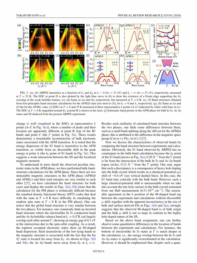
FIG. 3. (a), (b) ARPES intensities as a function of k‖ and EB at kz ∼ 0 (hν = 31 eV) and kz ∼ π (hν = 27 eV), respectively, measuredat T = 35 K. The EDC at point D is also plotted by the light blue curve in (b) to show the existence of a Fermi edge supporting the EF
crossing of the weak holelike feature. (c), (d) Same as (a) and (b), respectively, but measured at T = 6 K. (e), (f) Band structures obtainedfrom first-principles band-structure calculations for the AFM‖b state [see inset to (f)], for kz = 0 and π , respectively. (g), (h) Same as (e) and(f) but for the AFM‖c state. (i) EDCs at T = 6 and 35 K measured at three representative k points (A–C) indicated by white solid lines in (c).The EDC at T = 6 K magnified around EF at point B is shown in the inset. (j) Schematic band picture in the AFM phase for bulk In 5s, As 4pstates and SS deduced from the present ARPES experiment.
change is well visualized in the EDCs at representative kpoints [A–C in Fig. 3(c)], where a number of peaks and theirlocation are apparently different at point B (top of the B1band) and point C (the � point) in Fig. 3(i). These resultsdemonstrate a remarkable reconstruction of bulk electronicstates associated with the AFM transition. It is noted that theenergy dispersion of the S1 band is insensitive to the AFMtransition, as visible from no discernible shift in the peakenergy at point A (the kF point of S1 band) in Fig. 3(i). Thissuggests a weak interaction between the SS and the localizedmagnetic moment.
To understand in more detail the observed peculiar elec-tronic states in the AFM phase, we have performed bulk-band-structure calculations for the AFM phase. Since there are twometastable magnetic structures in the AFM phase (AFM‖band AFM‖c) and their total energies are very similar to eachother [27], we have calculated the band structure for bothcases and display the results in Figs. 3(e)–3(h) [note that thecalculation for the PM phase is technically difficult becausethe standard density functional theory (DFT) codes that dealwith the state at T = 0 K have difficulty in simulating therandom spin state at T > 0 K in the PM phase]. One cannotice that the global band structure is very similar betweenthe two phases. For instance, one commonly finds an invertedband structure where the electronlike In 5s conduction bandand the As 4p holelike valence band at kz = 0 (�K cut) largelyoverlap each other around �, showing an energy gap of 0.1 eVat the intersection due to the spin-orbit coupling. As a result,the topmost occupied electronic states show an M-shapedband dispersion. Such insensitivity of the low-lying bands tothe magnetic structure is associated with the fact that the Eu4 f state is located far away from EF. As shown in Figs. 3(f)and 3(h), the As 4p bands move away from EF at kz = π .
Besides such similarity of calculated band structure betweenthe two phases, one finds some differences between them,such as a small band splitting along the AH cut for the AFM‖bphase; this is attributed to the difference in the magnetic spacegroup (Cmcm vs P63′/m′m′c) [27].
Now we discuss the characteristics of observed bands bycomparing the band structure between experiments and calcu-lations. Obviously, the S1 band observed by ARPES has nocounterpart in the bulk-band calculation because the kF pointof the S1 band [arrows in Fig. 3(e); 0.20 Å−1 from the � point]is far from the intersection of the bulk In 5s and As 5p bands[open circles; 0.12 Å−1 from the � point]. One may arguethat such a discrepancy is a consequence of heavy hole dopinginto the bulk crystal which results in a chemical-potential (μ)shift of ∼0.4 eV (see vertical dashed lines). In this case, theS1 band may coincide with the bulk band. However, such alarge chemical-potential shift is unreasonable when we takeinto account the tiny hole carriers in the bulk crystal estimatedfrom our Hall measurement (6.5×1019 cm−3). The reason-able agreement in the k position of the M-shaped band topbetween the experiment and calculations without discernibleμ shift, together with the apparent inconsistency in the size ofbulk and surface-derived FSs in Figs. 1(d) and 2(a), stronglysuggests that the observed M-shaped band is of bulk originand the bulk μ shift is not so large in contrast to the highlyhole-doped nature of the SS.
Based on the above band assignment, one can furtherobserve some quantitative differences in the location of bandsbetween the experiment and calculations. For instance, thebottom of electronlike In 5s states at � is much deeper inthe calculation; i.e., the energy overlap between the In 5s andAs 4p states is significantly overestimated in the calculation.However, it should be emphasized that, despite such a quan-
033342-4

SIGNATURE OF BAND INVERSION IN THE … PHYSICAL REVIEW RESEARCH 2, 033342 (2020)
titative difference, the experimental band structure still main-tains the inverted character (i.e., M-shaped feature), which is aprerequisite for the realization of predicted topological phasesin the AFM state [27]. One can see from a direct comparisonof Fig. 3(c) and Figs. 3(e) and 3(g) that the experimental B2band is pushed upward by ∼0.4 eV compared to the calculatedcounterpart topped at EB ∼ 0.8 eV. Such a shift would becorrelated with the shallower In 5s electronlike feature in theexperiment.
As shown by a comparison of the electronic states atkz = π in Fig. 3(d) and Figs. 3(f) and 3(h), the ARPES resultand the calculated band structure share a common feature,i.e., a characteristic nonparabolic band dispersion called hereB4 [see dashed curve in Figs. 3(b) and 3(d)]. Since such anonparabolic band is absent in the experiment at kz ∼ 0 asseen in Fig. 3(c), it is inferred that the VUV-ARPES datacertainly reflect the intrinsic kz variation in the bulk-bandstructure. On the other hand, one can commonly recognize theM-shaped band near EF in both Figs. 3(c) and 3(d). A weaksignature of the holelike band that resembles the dispersionof the B2 band can be also seen in Fig. 3(d) (thin dashedcurve). This is unexpected from the calculated band structureat kz = π that shows a large gap of ∼0.6 eV below EF,suggesting that the ARPES intensity is influenced by both thekz-broadened and kz-selective spectral weights. Such a largekz-broadening effect is likely due to the short escape depthof photoelectrons excited by VUV photons together with thesmall BZ size along kz (0.35 Å−1), as also corroborated byobservation of an M-shaped band in a wide VUV-photon-energy range (hν = 20–40 eV). It is also inferred that theARPES intensity suffers from a strong matrix-element effect,judging from the observation that the holelike band which isobvious in the SX data in Fig. 1(f) is not clearly visible inthe VUV data in Fig. 3(a). The appearance of the M-shapedband in the AF phase despite the strong intensity suppressionin the PM phase suggests an interesting possibility that thematrix-element effect is different between the PM and AFMphases in the region where the strong band reconstructiontakes place. It is also remarked here that the linewidth of theARPES spectrum is not sharp enough to distinguish a possibledifference in the band structure expected from the calculationsfor AFM‖b and AFM‖c phases. It is necessary to pin downthe actual magnetic structure from other experiments such asneutron diffraction.
Now we discuss implications of the present results inrelation to the predicted topological phases. As illustrated inthe band diagram in Fig. 3(j), the ARPES data combined withthe band calculations suggest the occurrence of bulk-bandinversion at � in the AFM phase. The Fermi level is locatedclose to, but slightly above, the valence-band maximum due tothe hole doping. While the observed S1 band may merge intothe bulk conduction or valence bands, their actual connectivityis unclear due to the hole-doped nature. Nevertheless, it isinferred that the S1 band is a trivial SS originating from theAs-terminated surface and would likely be connected to thevalence band [see Fig. 3(j)], since a similar SS was predictedfor the P-terminated surface of a sister compound EuSn2P2
and confirmed by ARPES [15]. We speculate that, besides theS1 band, another topological Dirac-cone SS that is connectedto the B1 band may emerge in mainly the above-EF region
in EuIn2As2 (schematically shown by gray curves) [27] sincethe band inversion must be accompanied by the Dirac-cone SSwithin the spin-orbit gap. The existence of such a topologicalSS is also supported by our first-principles band calculationsby means of the Green’s function method (see Appendix Cfor details). A careful look at the EDC at T = 6 K at point Bshown in the inset to Fig. 3(j) suggests that there exists a Fermiedge cutoff besides a hump slightly away from EF originatingfrom the M-shaped band. This suggests that the observed gapat point B is not a full gap but an imperfect gap. This maybe consistent with the appearance of a weak topological SScrossing EF although this conjecture should be verified byvisualizing the full energy dispersion by experiments such astwo-photon ARPES.
According to the theory [27], the predicted axion-insulatorphase coexisting with the exotic TCI (for AFM‖b) or higher-order TI (for AFM‖c) requires an inverted band structure at �
as well as a gapped Dirac-cone band on some surfaces. Thus,from the present ARPES result, it can be said that EuIn2As2 inthe AFM phase is either a TI or an axion insulator, dependingupon whether or not a finite magnetic gap opens at the Diracpoint in the AFM phase. Clarification of the actual magneticstructure and observation of the Dirac-cone SS modulated bythe antiferromagnetism are the next important steps to furtherinvestigate the exotic physical properties associated with thetopological characteristics of EuIn2As2.
IV. SUMMARY
In conclusion, the present ARPES study of EuIn2As2 hasrevealed a band reconstruction associated with the AFM tran-sition together with a signature of bulk-band inversion in theAFM phase, consistent with the band calculation that supportsthe axion-insulator phase in EuIn2As2. The present study laysa foundation for understanding the interplay between AFMorder and nontrivial topology.
ACKNOWLEDGMENTS
We thank T. Saito, K. Horiba, M. Kitamura, andH. Kumigashira for their assistance in the ARPES ex-periments. This work was supported by Grant-in-Aid forScientific Research on Innovative Areas “Topological Mate-rials Science” (JSPS KAKENHI Grants No. JP15H05853 andNo. JP15K21717), JST-CREST (Grant No. JPMJCR18T1),JST-PRESTO (Grant No. JPMJPR18L7), and Grant-in-Aid for Scientific Research (JSPS KAKENHI Grants No.JP17H01139, No. JP18H04472, No. JP18H01160, No.JP18J20058, and No. JP17H04847), KEK-PF (Proposal No.2018S2-001), SLS (Proposal No. 20190829), and DIAMONDlight source (Proposal No. SI23799). The work at Beijing wassupported by the Natural Science Foundation of China (NSFCGrant No. 11734003), the National Key R&D Program ofChina (Grant No. 2016YFA0300600), and the Strategic Prior-ity Research Program of Chinese Academy of Sciences (GrantNo. XDB30000000). Z.W. acknowledges the support fromthe Beijing Institute of Technology Research Fund Programfor Young Scholars. A.A. acknowledges the Swiss NationalScience Foundation (Grant No. 200020B_188709).
033342-5
TAKAFUMI SATO et al. PHYSICAL REVIEW RESEARCH 2, 033342 (2020)
APPENDIX A: SAMPLE FABRICATION, ARPESEXPERIMENTS, AND BAND CALCULATIONS
High-quality EuIn2As2 single crystals were synthesized bythe flux method. High-purity Eu (lump), In (shot), and As(lump) were loaded into an Al2O3 crucible with the atomicratio of Eu:In:As = 1:12:3, and sealed into a quartz tube in avacuum of 2 × 10⁻⁶ Torr. The tube was heated up to 1373 Kin 20 h and held for 10 h at this temperature, then slowlycooled down to 973 K at a rate of 2 K/h, at which the fluxwas removed by centrifuge. Shiny crystals with typical size of2 × 2 × 0.2 mm3 were obtained.
SX and VUV ARPES measurements were performed withenergy-tunable synchrotron light at the SX-ARPES end sta-tion of the ADRESS beam line at the Swiss Light Source(SLS), Paul Scherrer Institute, Switzerland [30], and theHR-ARPES end station of the I05 beam line in the DI-AMOND light source, United Kingdom [31], respectively.SX- and VUV-ARPES measurements were performed with320–480 and 20–120 eV photons with p/circular and p-polarizations, respectively. The energy resolutions for SX-and VUV-ARPES measurements were 40–60 and 6–25 meV,respectively. Samples were cleaved in situ along the (001)crystal plane in an ultrahigh vacuum of 1 × 10⁻¹⁰ Torr. Thefirst-principles calculations were carried out by a projector-augmented wave method implemented in the Vienna Ab initioSimulation Package (VASP) [32] with generalized gradientapproximation (GGA) [33] and the Perdew-Burke-Ernzerhof(PBE) [34] type exchange-correlation potential. Fully opti-mized lattice constants of a = b = 4.2951 Å, and c =17.9583 Å, were used for the further calculations. The spin-orbit coupling was included self-consistently. A uniform gridof 13 × 13 × 5 was used for sampling the BZ [35]. Theenergy cutoff was set as 400 eV. To better process the on-siteCoulomb interactions, the Hubbard U parameter was set as5 eV for Eu 4 f electrons in the GGA+U calculations [36].
APPENDIX B: HALL MEASUREMENT
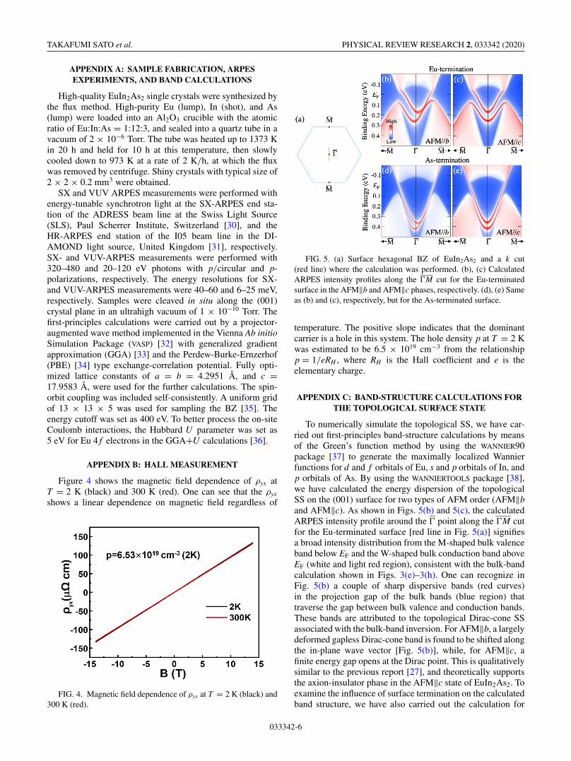
Figure 4 shows the magnetic field dependence of ρyx atT = 2 K (black) and 300 K (red). One can see that the ρyx
shows a linear dependence on magnetic field regardless of
FIG. 4. Magnetic field dependence of ρyx at T = 2 K (black) and300 K (red).
FIG. 5. (a) Surface hexagonal BZ of EuIn2As2 and a k cut(red line) where the calculation was performed. (b), (c) CalculatedARPES intensity profiles along the �M cut for the Eu-terminatedsurface in the AFM‖b and AFM‖c phases, respectively. (d), (e) Sameas (b) and (c), respectively, but for the As-terminated surface.
temperature. The positive slope indicates that the dominantcarrier is a hole in this system. The hole density p at T = 2 Kwas estimated to be 6.5 × 1019 cm−3 from the relationshipp = 1/eRH , where RH is the Hall coefficient and e is theelementary charge.
APPENDIX C: BAND-STRUCTURE CALCULATIONS FORTHE TOPOLOGICAL SURFACE STATE
To numerically simulate the topological SS, we have car-ried out first-principles band-structure calculations by meansof the Green’s function method by using the WANNIER90package [37] to generate the maximally localized Wannierfunctions for d and f orbitals of Eu, s and p orbitals of In, andp orbitals of As. By using the WANNIERTOOLS package [38],we have calculated the energy dispersion of the topologicalSS on the (001) surface for two types of AFM order (AFM‖band AFM‖c). As shown in Figs. 5(b) and 5(c), the calculatedARPES intensity profile around the � point along the �M cutfor the Eu-terminated surface [red line in Fig. 5(a)] signifiesa broad intensity distribution from the M-shaped bulk valenceband below EF and the W-shaped bulk conduction band aboveEF (white and light red region), consistent with the bulk-bandcalculation shown in Figs. 3(e)–3(h). One can recognize inFig. 5(b) a couple of sharp dispersive bands (red curves)in the projection gap of the bulk bands (blue region) thattraverse the gap between bulk valence and conduction bands.These bands are attributed to the topological Dirac-cone SSassociated with the bulk-band inversion. For AFM‖b, a largelydeformed gapless Dirac-cone band is found to be shifted alongthe in-plane wave vector [Fig. 5(b)], while, for AFM‖c, afinite energy gap opens at the Dirac point. This is qualitativelysimilar to the previous report [27], and theoretically supportsthe axion-insulator phase in the AFM‖c state of EuIn2As2. Toexamine the influence of surface termination on the calculatedband structure, we have also carried out the calculation for
033342-6

SIGNATURE OF BAND INVERSION IN THE … PHYSICAL REVIEW RESEARCH 2, 033342 (2020)
the As-terminated surface, and show the result in Figs. 5(d)and 5(e). One can recognize that the shifted and gapped Diraccones for the AFM‖b and AFM‖c phases, respectively, arealso seen in this calculation, whereas the Dirac point for both
AFM‖b and AFM‖c phases sinks well below EF relative tothat of the Eu-terminated surface [Figs. 5(b) and 5(c)]. Thissuggests that the energy position of topological SS relative tothat of the bulk band is highly surface-condition dependent.
[1] R. Yu, W. Zhang, H.-J. Zhang, S.-C. Zhang, X. Dai, andZ. Fang, Science 329, 61 (2010).
[2] C.-Z. Chang, J. Zhang, X. Feng, J. Shen, Z. Zhang, M. Guo, K.Li, Y. Ou, P. Wei, L. Wang, Z.-Q. Ji, Y. Feng, S. Ji, X. Chen, J.Jia, X. Dai, Z. Fang, S.-C. Zhang, K. He, Y. Wang, L. Lu, X.-C.Ma, and Q.-K. Xue, Science 340, 167 (2013).
[3] J. G. Checkelsky, R. Yoshimi, A. Tsukazaki, K. S. Takahashi,Y. Kozuka, J. Falson, M. Kawasaki, and Y. Tokura, Nat. Phys.10, 731 (2014).
[4] X. Kou, S.-T. Guo, Y. Fan, L. Pan, M. Lang, Y. Jiang, Q. Shao,T. Nie, K. Murata, J. Tang, Y. Wang, L. He, T.-K. Lee, W.-L.Lee, and K. L. Wang, Phys. Rev. Lett. 113, 137201 (2014).
[5] C.-Z. Chang, W. Zhao, D. Y. Kim, H. Zhang, B. A. Assaf,D. Heiman, S.-C. Zhang, C. Liu, M. H. W. Chan, and J. S.Moodera, Nat. Mater. 14, 473 (2015).
[6] Z. Qiao, S. A. Yang, W. Feng, W.-K. Tse, J. Ding, Y. Yao,J. Wang, and Q. Niu, Phys. Rev. B 82, 161414(R) (2010).
[7] X.-L. Qi, T. L. Hughes, and S.-C. Zhang, Phys. Rev. B 78,195424 (2008).
[8] R. Li, J. Wang, X.-L. Qi, and S.-C. Zhang, Nat. Phys. 6, 284(2010).
[9] X.-L. Qi, T. L. Hughes, and S.-C. Zhang, Phys. Rev. B 82,184516 (2010).
[10] Q. L. He, L. Pan, A. L. Stern, E. C. Burks, X. Che, G. Yin,J. Wang, B. Lian, Q. Zhou, E. S. Choi, K. Murata, X. Kou, Z.Chen, T. Nie, Q. Shao, Y. Fan, S.-C. Zhang, K. Liu, J. Xia, andK. L. Wang, Science 357, 294 (2017).
[11] M. Mogi, M. Kawamura, R. Yoshimi, A. Tsukazaki, Y. Kozuka,N. Shirakawa, K. S. Takahashi, M. Kawasaki, and Y. Tokura,Nat. Mater. 16, 516 (2017).
[12] D. Xiao, J. Jiang, J.-H. Shin, W. Wang, F. Wang, Y.-F. Zhao,C. Liu, W. Wu, M. H. W. Chan, N. Samarth, and C.-Z. Chang,Phys. Rev. Lett. 120, 056801 (2018).
[13] C. Yue, Y. Xu, Z. Song, H. Weng, Y.-M. Lu, C. Fang, andX. Dai, Nat. Phys. 15, 577 (2019).
[14] H. Li, S.-Y. Gao, S.-F. Duan, Y.-F. Xu, K.-J. Zhu, S.-J. Tian,J.-C. Gao, W.-H. Fan, Z.-C. Rao, J.-R. Huang, J.-J. Li, D.-Y.Yan, Z.-T. Liu, W. L. Liu, Y.-B. Huang, Y.-L. Li, Y. Liu, G.-B.Zhang, P. Zhang, T. Kondo, S. Shin, H.-C. Lei, Y.-G. Shi, W.-T.Zhang, H.-M. Weng, T. Qian, and H. Ding, Phys. Rev. X 9,041039 (2019).
[15] X. Gui, I. Pletikosic, H. Cao, H.-J. Tien, X. Xu, R. Zhong, G.Wang, T.-R. Chang, S. Jia, T. Valla, W. Xie, and R. J. Cava, ACSCent. Sci. 5, 900 (2019).
[16] B. Chen, F. Fei, D. Zhang, B. Zhang, W. Liu, S. Zhang, P.Wang, B. Wei, Y. Zhang, Z. Zuo, J. Guo, Q. Liu, Z. Wang, X.Wu, J. Zong, X. Xie, W. Chen, Z. Sun, S. Wang, Y. Zhang, M.Zhang, X. Wang, F. Song, H. Zhang, D. Shen, and B. Wang,Nat. Commun. 10, 4469 (2019).
[17] Y. Gong, J. Guo, J. Li, K. Zhu, M. Liao, X. Liu, Q. Zhang, L.Gu, L. Tang, X. Feng, D. Zhang, W. Li, C. Song, L. Wang, P.Yu, X. Chen, Y. Wang, H. Yao, W. Duan, Y. Xu, S.-C. Zhang,
X. Ma, Q.-K. Xue, and K. He, Chin. Phys. Lett. 36, 076801(2019).
[18] M. M. Otrokov, I. I. Klimovskikh, H. Bentmann, D. Estyunin,A. Zeugner, Z. S. Aliev, S. Gaß, A. U. B. Wolter, A. V.Koroleva, A. M. Shikin, M. Blanco-Rey, M. Hoffmann,I. P. Rusinov, A. Yu. Vyazovskaya, S. V. Eremeev, Yu. M.Koroteev, V. M. Kuznetsov, F. Freyse, J. Sánchez-Barriga,I. R. Amiraslanov, M. B. Babanly, N. T. Mamedov, N. A.Abdullayev, V. N. Zverev, A. Alfonsov, V. Kataev, B. Büchner,E. F. Schwier, S. Kumar, A. Kimura, L. Petaccia, G. Di Santo,R. C. Vidal, S. Schatz, K. Kißner, M. Ünzelmann, C. H. Min,Simon Moser, T. R. F. Peixoto, F. Reinert, A. Ernst, P. M.Echenique, A. Isaeva, and E. V. Chulkov, Nature (London) 576,416 (2019).
[19] Y.-J. Hao, P. Liu, Y. Feng, X.-M. Ma, E. F. Schwier, M. Arita,S. Kumar, C. Hu, R. Lu, M. Zeng, Y. Wang, Z. Hao, H.-Y. Sun,K. Zhang, J. Mei, N. Ni, L. Wu, K. Shimada, C. Chen, Q. Liu,and C. Liu, Phys. Rev. X 9, 041038 (2019).
[20] Y. J. Chen, L. X. Xu, J. H. Li, Y. W. Li, C. F. Zhang, H. Li,Y. Wu, A. J. Liang, C. Chen, S. W. Jung, C. Cacho, H. Y.Wang, Y. H. Mao, S. Liu, M. X. Wang, Y. F. Guo, Y. Xu,Z. K. Liu, L. X. Yang, and Y. L. Chen, Phys. Rev. X 9, 041040(2019).
[21] Y. Zhang, K. Deng, X. Zhang, M. Wang, Y. Wang, C. Liu, J.-W.Mei, S. Kumar, E. F. Schwier, K. Shimada, C. Chen, and B.Shen, Phys. Rev. B 101, 205126 (2020).
[22] S. Regmi, M. M. Hosen, B. Ghosh, B. Singh, G. Dhakal, C.Sims, B. Wang, F. Kabir, K. Dimitri, Y. Liu, A. Agarwal,H. Lin, D. Kaczorowski, A. Bansil, and M. Neupane,arXiv:1911.03703.
[23] S. Chowdhury, K. F. Garrity, and F. Tavazza, npj Comput.Mater. 5, 33 (2019).
[24] J. Li, Y. Li, S. Du, Z. Wang, B.-L. Gu, S.-C. Zhang, K. He,W. Duan, and Y. Xu, Sci. Adv. 5, eaaw5685 (2019).
[25] D. Zhang, M. Shi, T. Zhu, D. Xing, H. Zhang, and J. Wang,Phys. Rev. Lett. 122, 206401 (2019).
[26] J. Li, C. Wang, Z. Zhang, B.-L. Gu, W. Duan, and Y. Xu, Phys.Rev. B 100, 121103(R) (2019).
[27] Y. Xu, Z. Song, Z. Wang, H. Weng, and X. Dai, Phys. Rev. Lett.122, 256402 (2019).
[28] A. M. Goforth, P. Klavins, J. C. Fettinger, and S. M. Kauzlarich,Inorg. Chem. 47, 11048 (2008).
[29] N. Singh and U. Schwingenschlögl, Appl. Phys. Lett. 100,151906 (2012).
[30] V. N. Strocov, X. Wang, M. Shi, M. Kobayashi, J. Krempasky,C. Hess, T. Schmitt, and L. Patthey, J. Synchrotron Rad. 21, 32(2014).
[31] M. Hoesch, T. K. Kim, P. Dudin, H. Wang, S. Scott, P. Harris,S. Patel, M. Matthews, D. Hawkins, S. G. Alcock, T. Richter,J. J. Mudd, M. Basham, L. Pratt, P. Leicester, E. C. Longhi,A. Tamai, and F. Baumberger, Rev. Sci. Instrum 88, 013106(2017).
033342-7

TAKAFUMI SATO et al. PHYSICAL REVIEW RESEARCH 2, 033342 (2020)
[32] G. Kresse and J. Hafner, Phys. Rev. B 47, 558 (1993).[33] J. P. Perdew, J. A. Chevary, S. H. Vosko, K. A. Jackson, M. R.
Pederson, D. J. Singh, and C. Fiolhais, Phys. Rev. B 46, 6671(1992).
[34] J. P. Perdew, K. Burke, and M. Ernzerhof, Phys. Rev. Lett. 78,1396 (1997).
[35] H. J. Monkhorst and J. D. Pack, Phys. Rev. B 13, 5188 (1976)[36] S. L. Dudarev, G. A. Botton, S. Y. Savrasov, C. J. Humphreys,
and A. P. Sutton, Phys. Rev. B 57, 1505 (1998).
[37] A. A. Mostofi, J. R. Yates, Y.-S. Lee, I. Souza, D. Vanderbilt,and N. Marzari, Comput. Phys. Commun. 178, 685 (2008).
[38] Q.-S. Wu, S.-N. Zhang, H.-F. Song, M. Troyer, and A. A.Soluyanov, Comput. Phys. Commun. 224, 405 (2018).
[39] J. J. Yeh and I. Lindau:, At. Data Nucl. Data Tables 32, 1(1985).
[40] V. N. Strocov, M. Shi, M. Kobayashi, C. Monney, X. Wang,J. Krempasky, T. Schmitt, L. Patthey, H. Berger, and P. Blaha,Phys. Rev. Lett. 109, 086401 (2012).
033342-8