signals sampling & reconstruction (introduction)
TRANSCRIPT

Signals Sampling & Reconstruction (Introduction)
XMUT220 Signals and Systems

Topics
• Sampling of signals.
• Nyquist theorem.
• Aliasing.
• Reconstruction of signals.
• Discrete time processing of continuous-time signals.
• Analogue-to-digital converter and digital-to-analogue converter (ADC and DAC).
• Digital signal processing (DSP).
• Sampling of discrete-time signals.

Sampling of Signals
• Sampling of signals is the capture of a continuous-
time signal into a discrete-time signal.
• A common example is the conversion of a sound wave (
continuous signal) to a sequence of samples (a discrete-
time signal).

Sampling of Signals
• A sample is value or set of values at a point in time and/
or space.
• The number of samples taken during one second is called
the sample rate.
Requirements for Signal Sampling
Components required for performing signal sampling:
• Sampled signals – signals to be undergo sampling process.
• Sampling signal – a signal used as a reference for sampling of a given signal.
• Multiplier system – a system that enables sampling of the signals to be sampled with sampling signal.
• Algorithm for conversion – a type of process for converting from a given signal to its sample(s).

Requirements for Signal Sampling

Nyquist Theorem
• The highest frequency component in an analogue signal determines the bandwidth of that signal.
• According to the Nyquist Theorem, the sampling rate must be at least 2fmax, or twice the highest analogue frequency component.
Sampling rate = 2fmax
• If the sampling rate is less than 2fmax, some of the highest frequency components in the analogue input signal will not be correctly represented in the digitized output.
• When such a digital signal is converted back to analogue form by a digital-to-analogue converter, false frequency components appear that were not in the original analogue signal.

Nyquist Theorem
Sampling of Signals
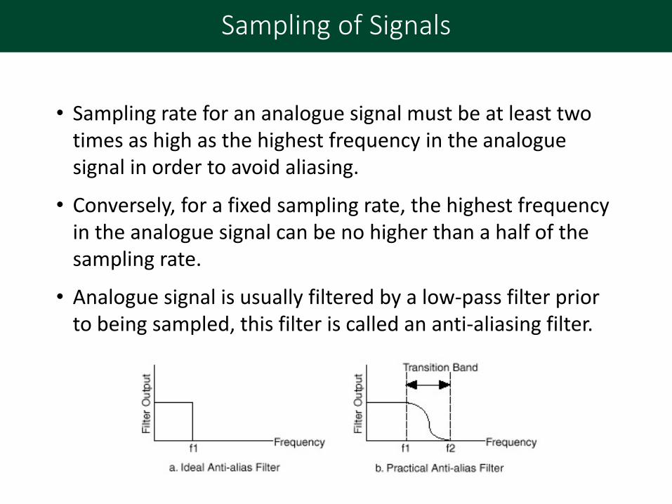
• Sampling rate for an analogue signal must be at least two times as high as the highest frequency in the analogue signal in order to avoid aliasing.
• Conversely, for a fixed sampling rate, the highest frequency in the analogue signal can be no higher than a half of the sampling rate.
• Analogue signal is usually filtered by a low-pass filter prior to being sampled, this filter is called an anti-aliasing filter.

Sampling Bandwidth & Frequency
Application Bandwidth Sampling Frequency
Biomedical < 500 Hz 1 kHz
Telephone speech < 4 kHz 8 kHz
Music < 20 kHz 44.1 kHz
Ultrasonic < 100 kHz 250 kHz
Radar < 100 MHz 200 MHz

Aliasing (Effect of Under Sampling)
• Aliasing is an effect that causes different signals to become indistinguishable (or aliases of one another) when sampled.
• It also refers to the distortion when the signal reconstructed from samples is different from the original continuous signal.

Aliasing (Effect of Under Sampling)
• For signals sampled in time, for instance digital audio, it is referred to as temporal aliasing.
• Sampled audio signal when it is reconstructed appears as a different audio signal e.g. original audio signal is higher frequency, but the reconstructed signal is lower frequency.
Sampling signal
Yellow – signal to be sampled
Blue – reconstructed signal

Moire Effect Raster Image/Jaggies/Pixelated
Aliasing (Effect of Under Sampling)
Aliasing can also occur in spatially sampled signals, for instance digital images, and is called spatial aliasing.
• Moiré effect is a visual perception that occurs when viewing a set of lines or dots that is superimposed on another set of lines or dots, where the sets differ in relative size, angle, or spacing.
• Raster images (or jaggies/pixelated) are stair-like lines that appear where there should be "smooth" straight lines or curves.
Reconstruction Methods
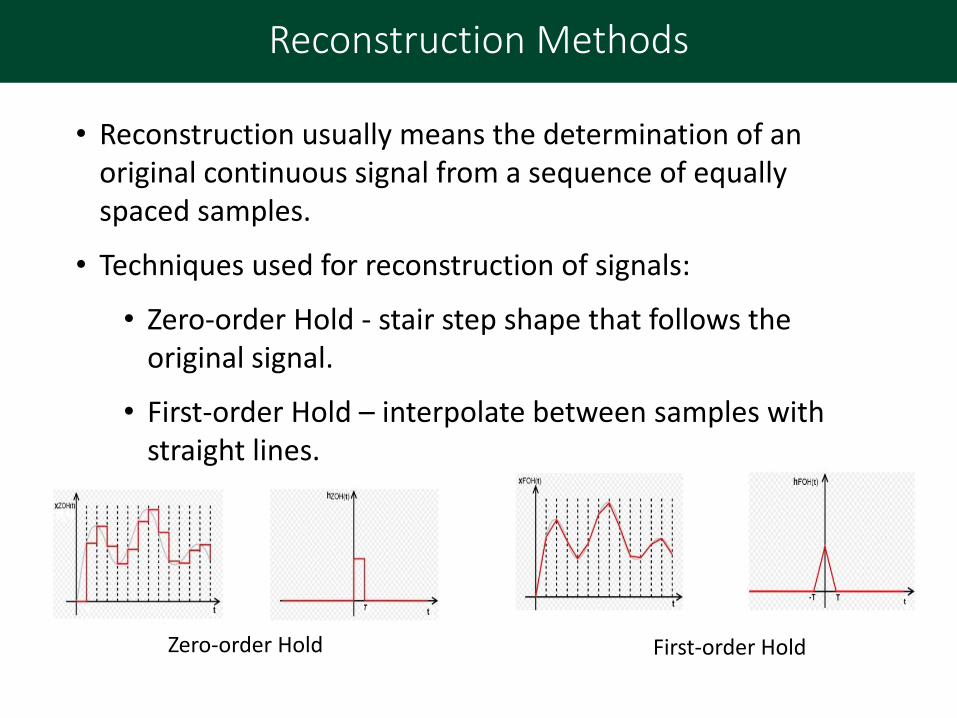
• Reconstruction usually means the determination of an original continuous signal from a sequence of equally spaced samples.
• Techniques used for reconstruction of signals:
• Zero-order Hold - stair step shape that follows the original signal.
• First-order Hold – interpolate between samples with straight lines.
Zero-order Hold First-order Hold

Reconstruction of Signals
Zero-Order Hold:
• It converts a discrete-time signal to a continuous-time signal by holding each sample value for one sample interval.
• It is realised with a conventional digital-to-analog converter (DAC).
Reconstruction of Signals
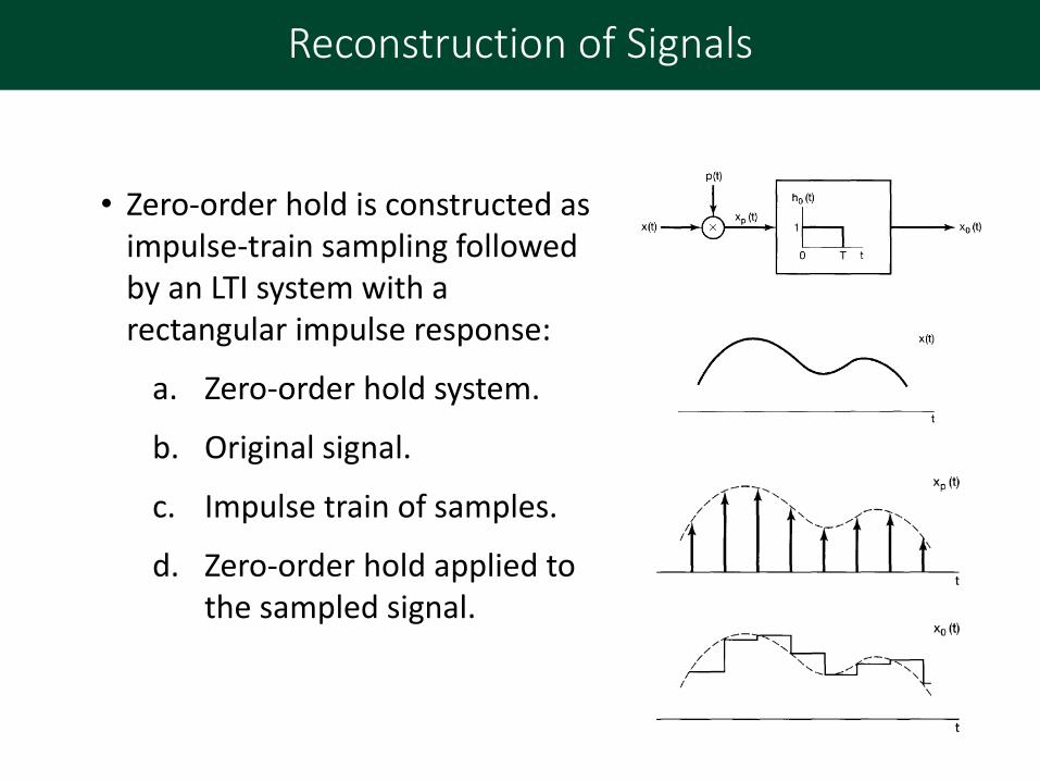
• Zero-order hold is constructed as impulse-train sampling followed by an LTI system with a rectangular impulse response:
a. Zero-order hold system.
b. Original signal.
c. Impulse train of samples.
d. Zero-order hold applied to the sampled signal.
Reconstruction of Signals
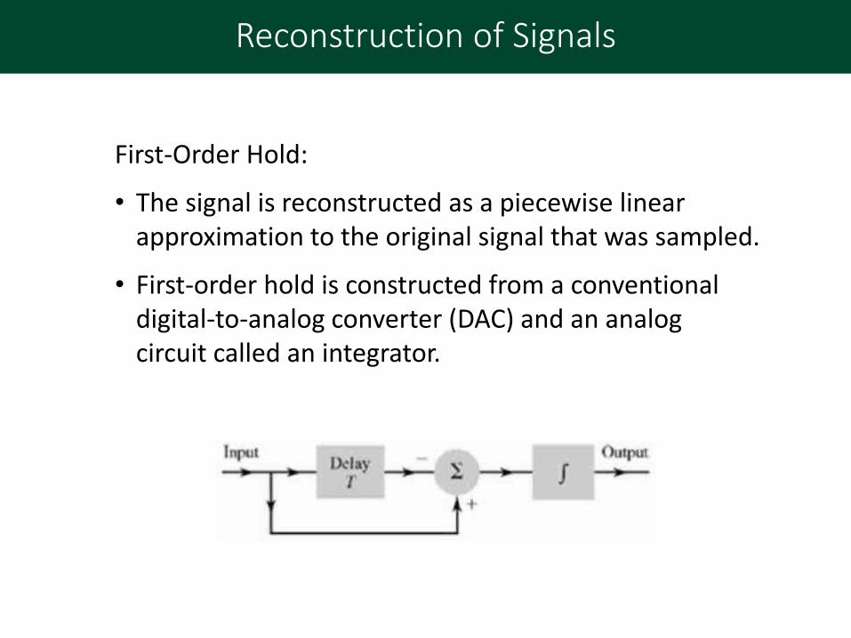
First-Order Hold:
• The signal is reconstructed as a piecewise linear approximation to the original signal that was sampled.
• First-order hold is constructed from a conventional digital-to-analog converter (DAC) and an analog circuit called an integrator.

Reconstruction of Signals
• First-order hold is made up as impulse-train sampling followed by convolution with a triangular impulse response:
a. First-order hold system.
b. Impulse train of samples.
c. Impulse response representing a first-order hold.
d. First-order hold applied to the sampled signal.
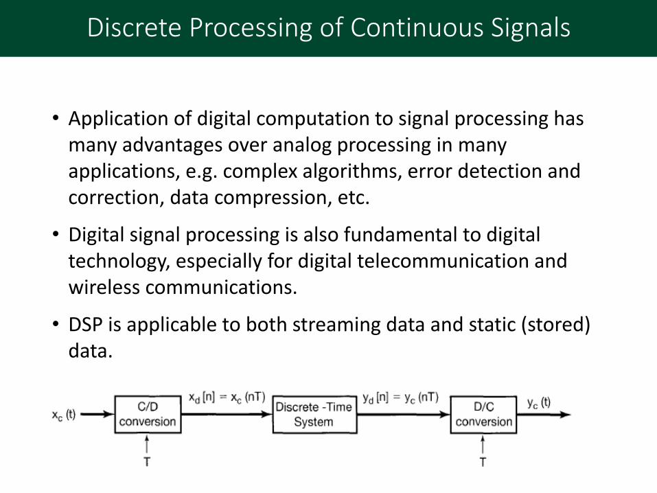
Discrete Processing of Continuous Signals
• Application of digital computation to signal processing has many advantages over analog processing in many applications, e.g. complex algorithms, error detection and correction, data compression, etc.
• Digital signal processing is also fundamental to digital technology, especially for digital telecommunication and wireless communications.
• DSP is applicable to both streaming data and static (stored) data.

Analog-to-Digital and Digital-to-Analog Conversions
• Analogue-to-digital conversions (ADC) change analog electrical data into digital signals (sampling).
• Digital-to-analogue conversions (DAC) attempt to create an analog output waveform from a digital signal (conversion/ reconstruction).
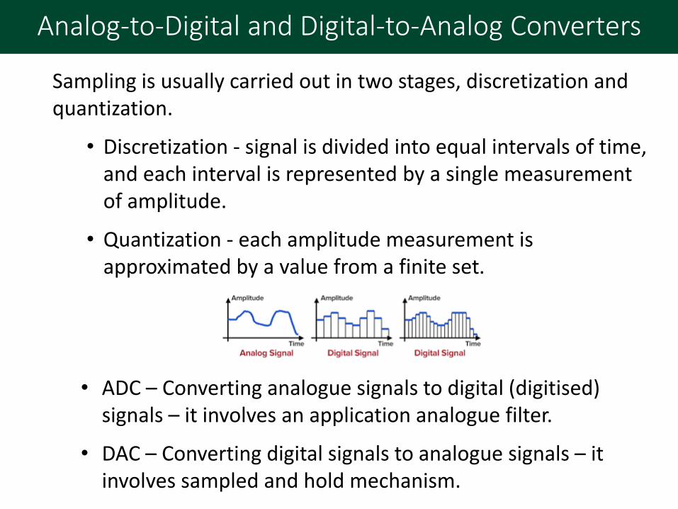
Analog-to-Digital and Digital-to-Analog Converters
Sampling is usually carried out in two stages, discretization and quantization.
• Discretization - signal is divided into equal intervals of time, and each interval is represented by a single measurement of amplitude.
• Quantization - each amplitude measurement is approximated by a value from a finite set.
• ADC – Converting analogue signals to digital (digitised) signals – it involves an application analogue filter.
• DAC – Converting digital signals to analogue signals – it involves sampled and hold mechanism.

Digital Signal Processing (DSP)
• Analogue Filter (Input) – Remove unwanted signals and noises.
• Digital Processing – Main signal processing of the system e.g. wave shaping, algorithm based processing, signal modulation, etc.
• Analogue Filter (Output) – Increase the quality and performance of the processed signal for the targeted system.

Digital Signal Processing (DSP)
• Digital Processing:
• Hardware unit e.g. amplification, wave shaping, digital filtering, advanced signal conversions, etc.
• Software unit e.g. algorithm of digital signal processing for manipulating the characteristics and properties of the signals.
• DSP applications include audio and speech processing, sensor processing, spectral density estimation, statistical signal processing, digital image processing, data compression, video and audio coding, image compression, etc.

Digital Signal Processing (DSP)
• Domains in digital signal processing: time domain (one-dimensional signals), spatial domain (multidimensional signals), frequency domain, and wavelet domains.
• The domain is chosen in which to process a signal by making an informed assumption (or by trying different possibilities) as to which domain best represents the essential characteristics of the signal and the processing to be applied to it.

Application of Digital Signal Processing (DSP)
• Digital filter system e.g. a system that performs mathematical operations on a sampled, discrete-time signal to reduce or enhance certain aspects of that signal.
• Filter is used for removing unwanted part of the signals, commonly these are noise, disturbance, unwanted signals, etc.
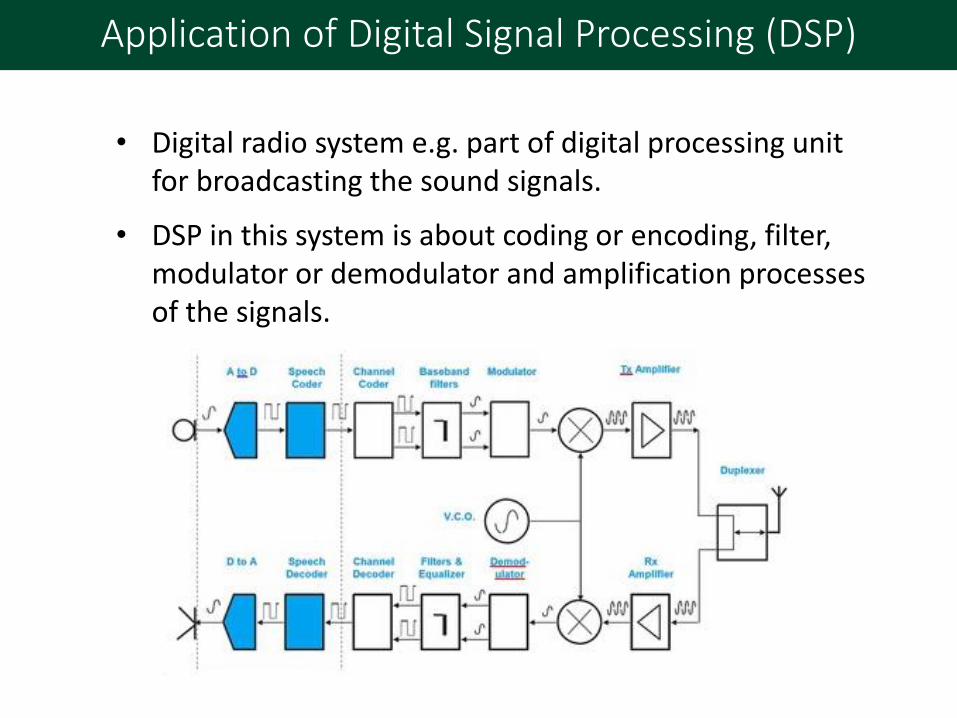
Application of Digital Signal Processing (DSP)
• Digital radio system e.g. part of digital processing unit for broadcasting the sound signals.
• DSP in this system is about coding or encoding, filter, modulator or demodulator and amplification processes of the signals.
Sampling of Discrete-Time Signals
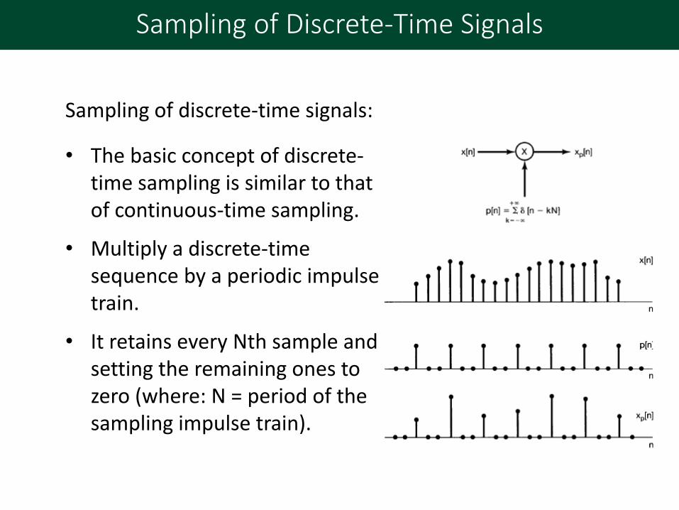
Sampling of discrete-time signals:
• The basic concept of discrete-time sampling is similar to that of continuous-time sampling.
• Multiply a discrete-time sequence by a periodic impulse train.
• It retains every Nth sample and setting the remaining ones to zero (where: N = period of the sampling impulse train).

Sampling of Discrete-Time Signals
a. Spectrum of original
signal.
b. Spectrum of sampling
sequence.
c. Spectrum of sampled
signal with 𝜔𝑠 > 2𝜔𝑀.
d. Spectrum of sampled
signal with 𝜔𝑠 < 2𝜔𝑀.
Note that aliasing occurs.
Effect in the frequency domain of impulse-train sampling of a
discrete-time signal:

Application of Sampling of Discrete-Time Signals
a. Block diagram for
sampling and
reconstruction of a band-
limited signal from its
samples.
b. Spectrum of the signal
𝑥 𝑛 .
c. Spectrum of 𝑥𝑝 𝑛 .
Exact recovery of a discrete-time signal from its samples using
an ideal low-pass filter:
Application of Sampling of Discrete-Time Signals
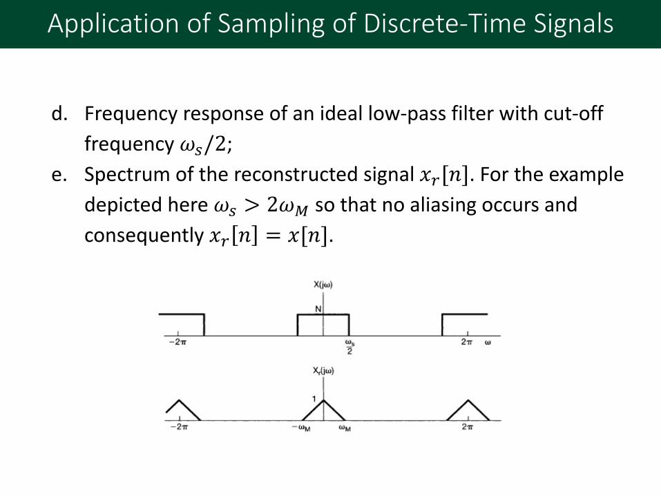
d. Frequency response of an ideal low-pass filter with cut-off
frequency 𝜔𝑠/2;
e. Spectrum of the reconstructed signal 𝑥𝑟[𝑛]. For the example
depicted here 𝜔𝑠 > 2𝜔𝑀 so that no aliasing occurs and
consequently 𝑥𝑟 𝑛 = 𝑥[𝑛].

Application of Sampling of Discrete-Time Signals
• Downsampling (decimation) isprocess of reducing the sampling rate. In practice, this usually implies low-pass-filtering a signal, then throwing away some of its samples.
• Downsampling factor is simply the ratio of the input rate to the output rate (e.g. M = input rate /output rate).
Time domain plot between 𝑥𝑝[𝑛] corresponding to
sampling and 𝑥𝑏[𝑛] corresponding to downsampling.
• Purpose: to operate at a lower sampling rate and to reduce the cost of process.

Application of Sampling of Discrete-Time Signals
• Frequency-domain illustration of the relationship between sampling and downsampling by a factor of M = 2.
Application of Sampling of Discrete-Time Signals
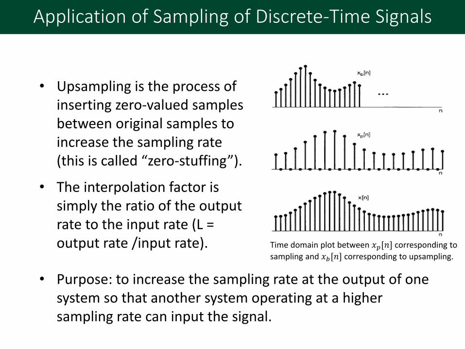
• Upsampling is the process of inserting zero-valued samples between original samples to increase the sampling rate (this is called “zero-stuffing”).
• The interpolation factor is simply the ratio of the output rate to the input rate (L = output rate /input rate).
• Purpose: to increase the sampling rate at the output of one system so that another system operating at a higher sampling rate can input the signal.
Time domain plot between 𝑥𝑝[𝑛] corresponding to
sampling and 𝑥𝑏[𝑛] corresponding to upsampling.

Application of Sampling of Discrete-Time Signals
• Frequency domain illustrations show sequences and spectra
for upsampling by a factor of L = 2.