signal animator2 instructions rev3
TRANSCRIPT

1
21175 Tomball Pkwy Phone: (281) 251-5813 Suite 287 email: [email protected] Houston, TX 77070 http://www.logicrailtech.com
Signal Animator/2 Instructions (covers versions SA/2, SA/2-IR and SA/2-X)
Revised 11/7/2020
Getting started Thank you for purchasing a Logic Rail Technologies product! Please read all instructions prior to installing this board. You’re probably wondering why such a relatively simple product like this needs so many pages of instructions! We have two reasons. First, the Signal Animator/2 is extremely versatile and can be used with a wide variety of signals. Second, we’d rather provide you with too much information rather than not enough!
The Signal Animator/2 provides automatic operation of a 3-color block signal in a semi-prototypical way. A photocell or a pair of infrared components, hereafter called the “sensor”, is used for train detection. The signal will be normally green. Anytime the sensor is covered by any portion of a train the signal will turn red. Once the sensor is uncovered the Signal Animator/2 will delay (time adjustable, see below) and then change the signal to yellow. After another equal time delay the signal will be changed back to green. What’s different from the original version of the Signal Animator (SA-1 and SA-1-IR)? Signal outputs are turned on in sequence (Red Yellow Green), briefly, when power is first applied to the
board. This gives you a quick test of your signal to make sure all the connections are correct and the signal works! The time delay between color changes is now adjustable from 1 to 127 seconds! You’re no longer limited to one of
two delay times. We’ve integrated the “random” mode feature which was previously a separate product. You can turn this on or
off! There’s no need to swap chips on the board if you want to use a photocell, infrared between-the-rails or infrared
across-the-rails. However, you will need to decide which sensor type (photocell or infrared) you want at time of purchase. Both sensor types are still available separately (#PCELL or #BTR-IR1) if you want to change types!
The infrared detection method has been improved and no longer has strict limits on the incoming voltage. No more little jumpers (shunts) to lose!
The SA/2 or SA/2-IR version of the Signal Animator/2 provides 3-color signaling for LED-based 3-light (common anode) and searchlight-style signals. The signal outputs are capable of providing ~20mA per output.
You should make all connections to the circuit board before applying power to it. You can mount the board anywhere it is convenient underneath your layout using the four mounting holes provided. The holes will accept #4 screws; do not enlarge the holes as damage to the circuit board can result and your warranty will be voided!
2-lead/3-lead LED Searchlight Signals (older Tomar Industries, Oregon Rail Supply, etc) To select a 2 or 3 lead searchlight signal on the Signal Animator/2 you must have switch labeled SIG_TYPE in the ON position as shown in Figure 1. The type of LED used in these model searchlight signals is commonly called a bipolar or tri-color LED. This LED has two elements inside of a single housing; one element is green and the other is red. There are two ways that these LEDs are internally wired. One has two leads and the other has three leads; the three-leaded variety is the most common. The Signal Animator/2 supports either one as shown in Figures 2a & 2b. You MUST use resistors with LED-based signals! Because the Signal Animator/2 provides +5V power to the LED we recommend a resistor value of 150 ohms. We have included three resistors with this product; you can use higher value resistors if you wish!
Figure 1 – selecting 2-lead or 3-lead searchlight signals
Figure 2a – 2-lead searchlight signal Figure 2b – 3-lead searchlight signal
LOGICTECHNOLOGIES
RAIL"SophisticatedModel RailroadElectronics"
TM

2
You can adjust the yellow hue on an LED searchlight signal using the switch labeled YEL_HUE on the circuit board. If the switch is in the OFF position, as shown in Figure 3, then the yellow hue will be more reddish and less green; if the switch is in the ON position then the yellow hue will be more greenish and less red.
Figure 3
adjusting yellow hue
Signals with 3 LEDs (Tomar Industries, Oregon Rail Supply, all BLMA, etc) To select signals using 3 individual LEDs (this INCLUDES searchlight signals from BLMA/Atlas and the newer searchlight signals from Tomar) you must have the switch labeled SIG_TYPE in the OFF position as shown in Figure 4. The Signal Animator/2 directly controls 3-light LED signals wired in a common-anode (the anode is the positive side of the LED) arrangement. Virtually all brands of 3-light signals are wired this way. Two known exceptions are signals from Integrated Signal Systems which typically wire their signals in a common-cathode arrangement and the Atlas 3-light circular head (not searchlight) signals. We offer the Signal Animator/2 version SA/2-CC or SA/2-CC-IR for that type of signal wiring.
Figure 4 –selecting 3-LED signals
You MUST use resistors with LED-based signals! Because the Signal Animator/2 provides +5V power to the LED we recommend a resistor value of 150 ohms. We have included three resistors with this product; you can use higher value resistors if you wish! Since only one LED will be illuminated at a time you can choose to use a single resistor in the common anode path or individual resistors in each of the LED cathode paths. The individual resistor scheme is illustrated in Figure 5. You MUST connect the positive common wire to the +5V terminal. You will damage the Signal Animator/2 if you use a different voltage!!!
Figure 5 – 3-light signal Sensor modes The Signal Animator/2 supports four different sensor (detector) modes: photocell, between-the-rails infrared, across-the-rails infrared, and external detector. When you purchased this product it either came with a photocell, infrared components or neither (board only, for use with an external detector). The sensor mode is selected using the switches labeled SEN_TYPE and SEN_POL as depicted in the Table 1 below.
Photocell
SEN_TYPE – OFF SEN_POL - OFF
Between-the-rails Infrared SEN_TYPE – ON SEN_POL - ON
Across-the-rails Infrared SEN_TYPE – ON SEN_POL - OFF
External Detector SEN_TYPE – OFF
SEN_POL - ON
Table 1 – Sensor mode selection

3
Using a Photocell for train detection The photocell should be mounted between the rails in the general area where you will locate the signal. Drill a 9/64" hole through the ballast, roadbed, and sub-roadbed. For the smaller scales this drilling may end up hitting the ties. Take your time so you don’t mangle them! Figure 6a illustrates the placement of the photocell in between the rails. Insert the leads of the photocell into the hole from the top of your layout. One of the photocell leads has a piece of insulation on it so be sure the two leads don't touch each other! If the leads do not protrude enough from the underside of your layout then it will be necessary to extend the leads; soldering wires to them is the most common method; make sure you insulate any connections you make to the photocell leads so that they don't short out. Once you have wired the photocell to the Signal Animator/2 (see Figure 6b) and verified its operation you may wish to put a dab of white glue under the photocell to hold it in place; make sure you don't get glue on the top surface of the photocell as this may prevent it from operating properly. The photocell requires a light source above it to function properly. On most layouts the room lighting should be sufficient. However, if the photocell is located in an area that doesn't get much overhead lighting or if you have simulated "nighttime" operations then it will be necessary to locate a light source on the layout near the photocell.
Figure 6a – photocell placement
Figure 6b – photocell wiring Streetlights and yard lights are common light sources. Locate the light source slightly to the left or right of the photocell and not directly over it; this will allow the Signal Animator/2 to still properly detect a train that has stopped over the photocell with the gap between cars over the photocell. You can adjust the sensitivity of the photocell on the circuit board using a small slotted head screwdriver. Insert the screwdriver in the component labeled "ADJ". Turning the screwdriver clockwise will compensate for lower light levels. With nothing blocking the photocell turn the screwdriver clockwise until the signal changes to red. Then slightly turn the screwdriver counter-clockwise; after the time delay the signal should change to yellow. Repeat if necessary. Using Between-the-rails Infrared
With this sensor mode and physical arrangement a train is detected when the infrared (IR) beam is reflected on the underside of the train. The IR components should be mounted between the rails. Drill two 11/64” holes, through the ballast, roadbed, and sub-roadbed. These holes should be located one tie apart (Figure 7a) and drilled at a slight angle from vertical towards each other as illustrated in the side view in Figure 7b. The benefit of mounting them at an angle is increased detection reliability in smaller scales or irregular bottoms on rolling stock. For the smaller scales this drilling may end up hitting the ties. Take your time so you don’t mangle them! Insert the leads of one IR emitter (white and black wires) into one of the holes (it doesn’t matter which one!) from the top of your layout. Repeat for the IR detector (blue and black wires). The tops of the components should sit no higher than the top of the ties for optimal IR performance; in some cases (e.g. false triggering) it may be necessary to locate the components a little below the ballast line. You can extend the leads with similar (or larger) wire. We recommend soldering and insulating these connections. We also recommend using terminal blocks/strips since you’ll have multiple connections to make. Once you have wired the IR components and verified their operation you may wish to put a dab of white glue or silicone caulk where the wires exit the holes underneath the layout. This will help to hold the components in place; make sure you don't get any
Figure 7a
Figure 7b
substance (e.g. ballast or glue) on the top surface of the IR components as this may prevent them from operating properly. In extreme cases where you may be getting interference from overhead lighting you can mount the IR detector in some plastic or metal tubing. You can also recess the IR detector slightly below the ties and roadbed.
Using Across-the-rails Infrared With this sensor mode and physical arrangement a train is detected when the infrared (IR) beam is broken by the train. The IR components should be located across the track as shown in Figure 8a and 8b. The detector (dark lens, blue and black wires) should be mounted with a slight downward angle in order to minimize the possibility of false triggering from visible light sources; this is illustrated in Figure 8a. We would also recommend that you angle the emitter and detector across the track as shown in Figure 8b. This will minimize false “clear” situations due to the space between rolling stock. You can bend the IR emitter and detector components IF you are VERY careful and, preferably, use a pair of
Figure 8a
4
“smooth jaw” (no teeth/serration) pliers!! Make the bend on the IR component NO CLOSER than 0.5” from the tip. You don’t want to pierce the insulated heat shrink tubing and potentially cause a short.
In the event the leads don’t reach the circuit board you can extend them with similar (or larger) wire. We recommend soldering these connections or using terminal blocks/strips especially when you have multiple connections to make.
Aligning the IR components for reliable detection might be a bit challenging. We recommend the use of a straight edge or ruler for initial “rough” alignment. You can tweak the final alignment once you’re ready to test the circuit.
Since the IR components are located trackside, you’ll probably want to consider “hiding” them. There are numerous ways to do this such as using shrubbery, small equipment buildings or fixtures. We leave this exercise up to your imagination and creativity! We would strongly suggest that you get the circuitry working properly first, and then address the physical appearance.
Figure 8b
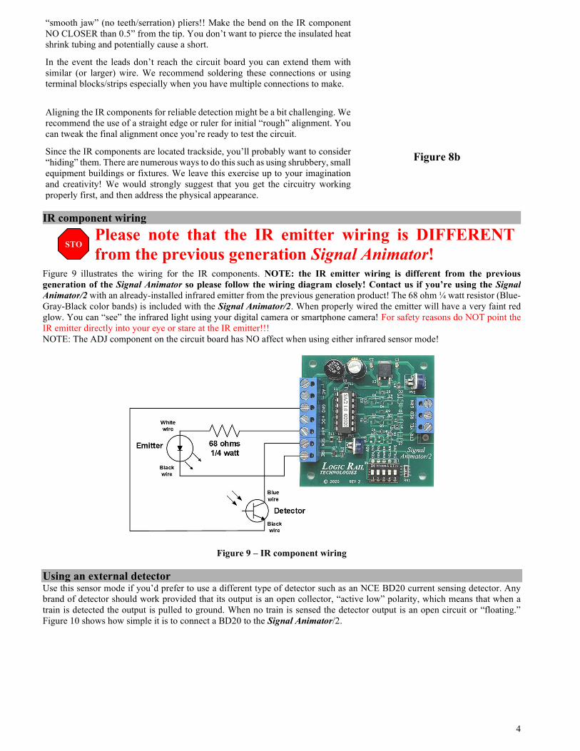
IR component wiring
Please note that the IR emitter wiring is DIFFERENT from the previous generation Signal Animator!
Figure 9 illustrates the wiring for the IR components. NOTE: the IR emitter wiring is different from the previous generation of the Signal Animator so please follow the wiring diagram closely! Contact us if you’re using the Signal Animator/2 with an already-installed infrared emitter from the previous generation product! The 68 ohm ¼ watt resistor (Blue-Gray-Black color bands) is included with the Signal Animator/2. When properly wired the emitter will have a very faint red glow. You can “see” the infrared light using your digital camera or smartphone camera! For safety reasons do NOT point the IR emitter directly into your eye or stare at the IR emitter!!! NOTE: The ADJ component on the circuit board has NO affect when using either infrared sensor mode!
Figure 9 – IR component wiring Using an external detector Use this sensor mode if you’d prefer to use a different type of detector such as an NCE BD20 current sensing detector. Any brand of detector should work provided that its output is an open collector, “active low” polarity, which means that when a train is detected the output is pulled to ground. When no train is sensed the detector output is an open circuit or “floating.” Figure 10 shows how simple it is to connect a BD20 to the Signal Animator/2.
STOP

5
Figure 10 – External detector wiring (NCE BD20 shown)
Signal color change delay The signal color change delay can be adjusted between approximately 1 and 127 seconds. The delay time is adjusted using a flat blade screwdriver inserted into the “pot” labeled “DELAY” on the circuit board. If you rotate it fully to the left you’ll get the minimum time delay. Rotating it fully to the right will give you the maximum time delay. Set the delay based on your own personal preference. On smaller layouts you may wish to have a shorter delay so that a looping train doesn’t run into a red or yellow signal it just caused itself! You can change the delay time as you wish even when the power to the Signal Animator/2 is on.
Figure 11 – time delay
Power The Signal Animator/2 accepts AC or DC power (7 - 16V). Power consumption for LED signals is approximately 35mA (board plus signal). If you are only using a single board then you can use the AC terminals to provide power as shown in Figure 12a. You can use the accessory terminals on your throttle/power pack. If you are using more than one Signal Animator/2 you should consider powering them all from a single DC source as shown in Figure 12b. Watch the polarity and make sure you know what is positive! Contact us if you are uncertain! When power is first applied the signal outputs will turn on briefly in sequence (Red Yellow Green).
Figure 12a – AC or DC power to a single board Figure 12b – DC power
Random mode The Signal Animator/2 incorporates a “random” mode. This may be useful if you wish to simulate phantom trains along your mainline or perhaps at a junction. At random times the signal will turn red, delay some amount of time (which varies from one random event to the next), turns the signal yellow, delays, then turns the signal back to green. To enable this mode put the switch labeled RANDOM in the ON position as shown in Figure 13. You can use this mode with or without train detection. If you do NOT want train detection (i.e. random trains only) then don’t connect anything to the SEN terminal AND configure the Sensor mode for an external detector (see Table 1 on page 2).
Figure 13 – Random mode enable
Other Applications Please contact us if you are interested in knowing how to interlock your signal (i.e. force it to red) with the position of a turnout or if you are interested in controlling a dual head signal with two Signal Animator/2 boards. You can also access this documentation online from our website at http://www.logicrailtech.com/lrt_docs.htm

6
Troubleshooting – photocell sensing If your signal is not changing colors when the sensor is covered or stays red all the time you can perform the following tests. First, verify that you have the sensor mode configured correctly (see Table 1 on page 2). Second, disconnect the photocell. With no photocell connected the Signal Animator/2 will turn on the red output and keep it on. If the signal stays green then you either have the signal wired backwards (reverse RED and GRN connections) or the Signal Animator/2 or photocell is faulty. You can also temporarily connect the GND terminal to the SEN terminal. The Signal Animator/2 will turn on the green output and keep it on. If the signal stays red (allow for the delay period to expire) then you either have the signal wired backwards (reverse RED and GRN connections) or the Signal Animator/2 or photocell is faulty. Troubleshooting – Between-the-rails infrared sensing PLEASE double check the IR emitter wiring ESPECIALLY if you have our older generation products. This is the most common mistake customers make. Does the IR emitter appear to be blinking on and off? Make sure that the IR emitter and IR detector are only ONE railroad tie apart, no higher than the top of the ties and mounted just slightly off vertical. If your signal is not changing colors when the sensor is activated or stays red all the time you can perform the following tests. First, verify the sensor wiring previously described and verify the red glow of the IR emitter using a digital camera or smartphone camera. Also verify that you have the sensor mode configured correctly (see Table 1 on page 2). If the signal stays red all of the time then disconnect the IR detector’s blue wire. After two time delays the signal should return to green. If it does then there is a problem with the IR detector. If your signal never changes from green then temporarily connect a wire between the SEN PC terminal and the GND terminal AND change the sensor mode to External Detector (see Table 1 on page 2). The signal should immediately change to red. If not, then the Signal Animator/2 board should be returned to us for test/repair. If the signal did change to red then disconnect the temporary wire. The signal should proceed through its delay and color changes. If so then the problem lies with the IR detector. Don’t forget to configure the sensor mode properly again! Warranty This product is warranted to be free from defects in materials or workmanship for a period of one year from the date of purchase. Logic Rail Technologies reserves the right to repair or replace a defective product. The product must be returned to Logic Rail Technologies in satisfactory condition. This warranty covers all defects incurred during normal use of this product. This warranty is void under the following conditions: 1) If damage to the product results from mishandling or abuse. 2) If the product has been altered in any way (e.g. soldering to the circuit board). 3) If the current or voltage limitations of the product have been exceeded. Requests for warranty service must include a dated proof of purchase, a written description of the problem, and return shipping and handling ($8.00 inside U.S./$20.00 outside U.S. - U.S. funds only). Except as written above, no other warranty or guarantee, either expressed or implied by any other person, firm or corporation, applies to this product. Technical Support We hope the preceding instructions sufficiently answer any questions you might have about the installation of this product. However, technical support is available should you need it. You can reach us via phone or email; see the top of page 1.