sign support manual...sign support manual 2019 02 15 table of contents page iii 4.5.4.2 cantilever...
TRANSCRIPT

Ministry of Transportation Provincial Highways Management Division Highway Standards Branch Bridge Office
February 2019
SIGN SUPPORT MANUAL

ISBN 978-1-4868-2743-5 © The Queen’s Printer for Ontario.
Reproduced with permission.
Although the contents of this manual have been checked no warranty, expressed or implied, is made by the Ministry of Transportation as to the accuracy of the contents of this manual, nor shall the fact of distribution constitute any such warranty, and no responsibility is assumed by the Ministry of Transportation in any connection therewith. It is the responsibility of the user to verify its currency and appropriateness for the use intended, to obtain the revisions, and to disregard obsolete or inapplicable information.
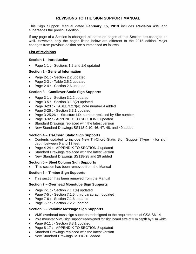
REVISIONS TO THE SIGN SUPPORT MANUAL This Sign Support Manual dated February 15, 2019 includes Revision #15 and supersedes the previous edition.
If any page of a Section is changed, all dates on pages of that Section are changed as well. However, only the pages listed below are different to the 2015 edition. Major changes from previous edition are summarized as follows. List of revisions
Section 1 - Introduction
Page 1-1 : - Sections 1.2 and 1.6 updated
Section 2 - General Information
Page 2-1 : - Section 2.2 updated Page 2-3 : - Table 2.5.2 updated Page 2-4 : - Section 2.6 updated
Section 3 – Cantilever Static Sign Supports
Page 3-1 : - Section 3.1.2 updated Page 3-5 : - Section 3.1.8(2) updated Page 3-23 : - TABLE 3.2.3(a), note number 4 added Page 3-25 : - Section 3.3.1 updated Page 3-25,26 : - Structure I.D. number replaced by Site number Page 3-32 : - APPENDIX TO SECTION 3 updated Standard Drawings replaced with the latest version New Standard Drawings SS118-9,10, 46, 47, 48, and 49 added
Section 4 – Tri-Chord Static Sign Supports
Contents updated to include New Tri-Chord Static Sign Support (Type II) for sign depth between 9 and 13 feet.
Page 4-24 : - APPENDIX TO SECTION 4 updated Standard Drawings replaced with the latest version New Standard Drawings SS118-28 and 29 added
Section 5 – Steel Column Sign Supports This section has been removed from the Manual
Section 6 – Timber Sign Supports
This section has been removed from the Manual Section 7 – Overhead Monotube Sign Supports
Page 7-1 : - Section 7.1.1(e) updated Page 7-5 : - Section 7.1.5, third paragraph updated Page 7-6 : - Section 7.1.6 updated Page 7-7 : - Section 7.2.2 updated Section 8 – Variable Message Sign Supports
VMS overhead truss sign supports redesigned to the requirements of CSA S6-14 Pole mounted VMS sign support redesigned for sign board size of 3 m depth by 5 m width Page 8-11 : - Section 8.3.1 updated Page 8-17 : - APPENDIX TO SECTION 8 updated Standard Drawings replaced with the latest version New Standard Drawings SS118-13 added.

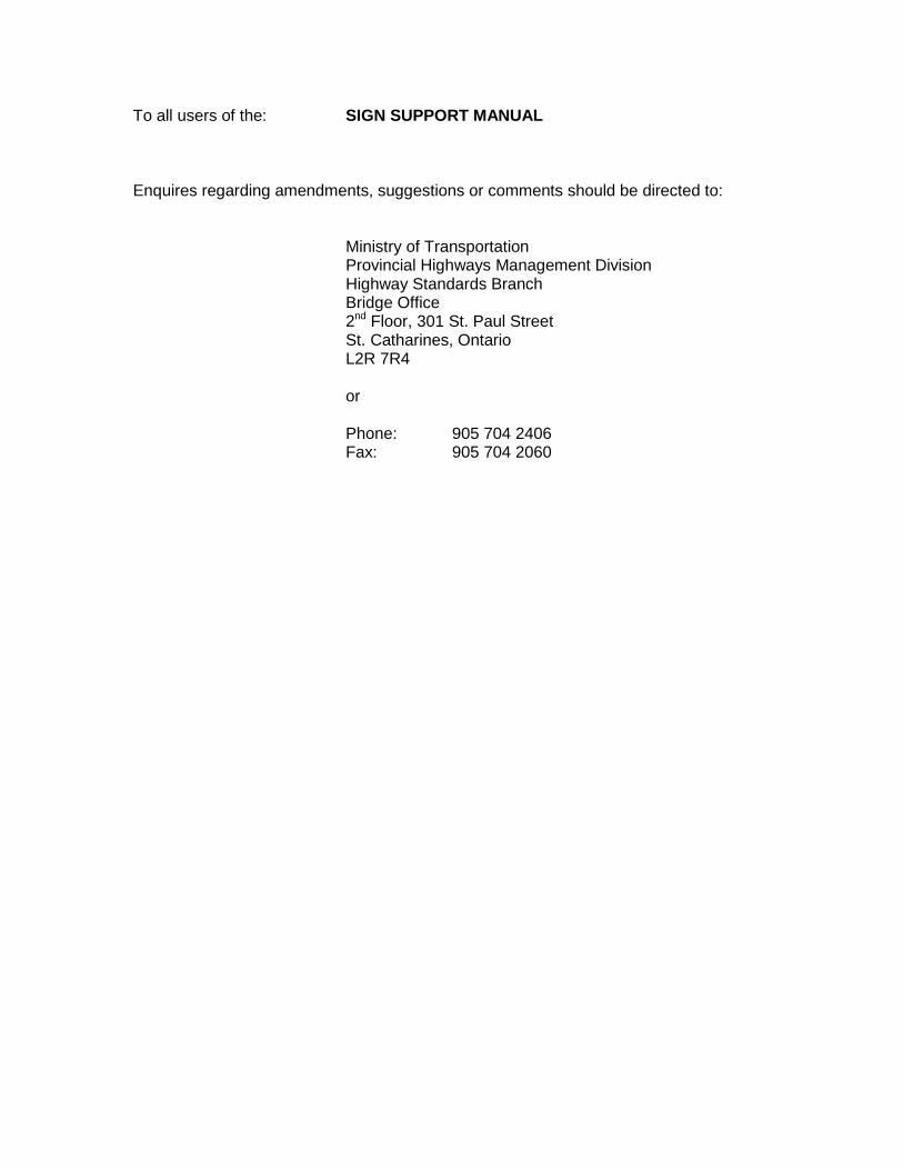
To all users of the: SIGN SUPPORT MANUAL Enquires regarding amendments, suggestions or comments should be directed to:
Ministry of Transportation Provincial Highways Management Division Highway Standards Branch Bridge Office 2nd Floor, 301 St. Paul Street St. Catharines, Ontario L2R 7R4 or Phone: 905 704 2406 Fax: 905 704 2060

This page is intentionally left blank.
.

SIGN SUPPORT MANUAL
TABLE OF CONTENTS
February 2019

SIGN SUPPORT MANUAL
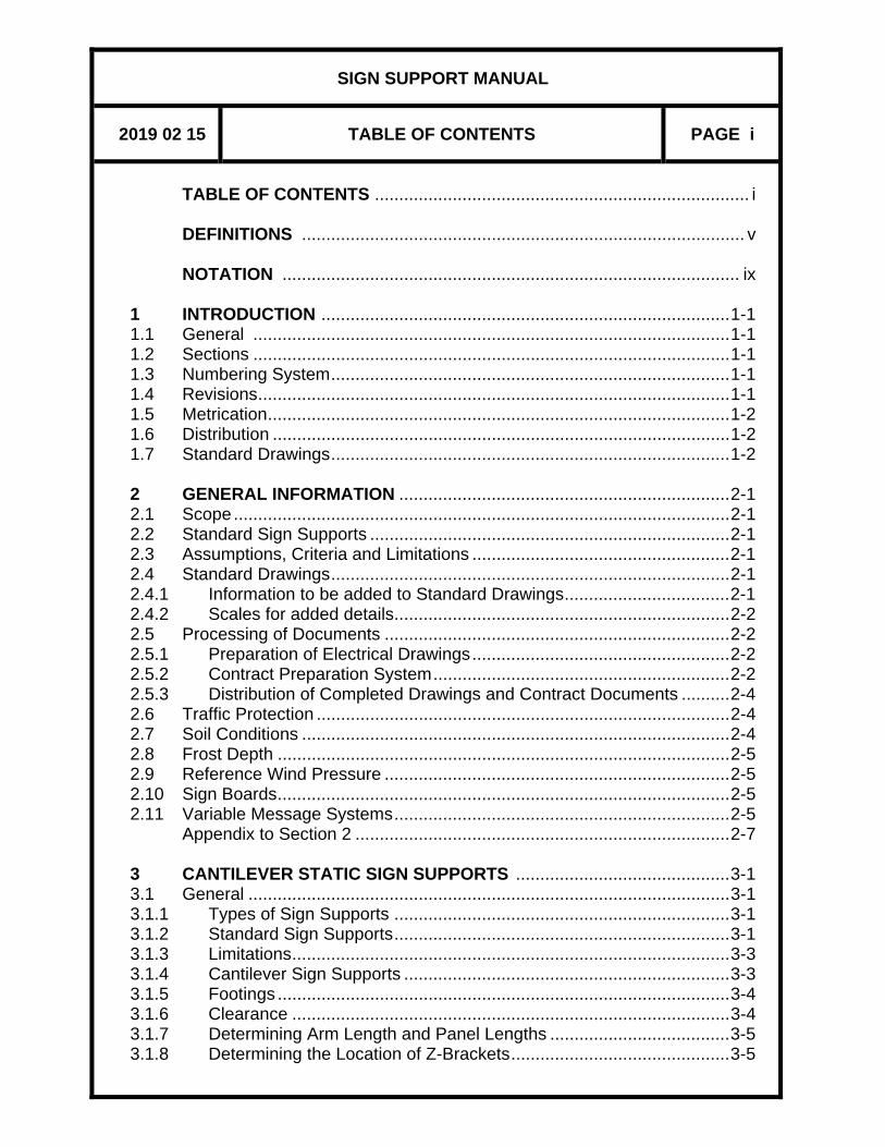
2019 02 15 TABLE OF CONTENTS PAGE i
TABLE OF CONTENTS ............................................................................. i DEFINITIONS ........................................................................................... v NOTATION .............................................................................................. ix 1 INTRODUCTION .................................................................................... 1-1 1.1 General .................................................................................................. 1-1 1.2 Sections .................................................................................................. 1-1 1.3 Numbering System .................................................................................. 1-1 1.4 Revisions ................................................................................................. 1-1 1.5 Metrication ............................................................................................... 1-2 1.6 Distribution .............................................................................................. 1-2 1.7 Standard Drawings .................................................................................. 1-2 2 GENERAL INFORMATION .................................................................... 2-1 2.1 Scope ...................................................................................................... 2-1 2.2 Standard Sign Supports .......................................................................... 2-1 2.3 Assumptions, Criteria and Limitations ..................................................... 2-1 2.4 Standard Drawings .................................................................................. 2-1 2.4.1 Information to be added to Standard Drawings .................................. 2-1 2.4.2 Scales for added details ..................................................................... 2-2 2.5 Processing of Documents ....................................................................... 2-2 2.5.1 Preparation of Electrical Drawings ..................................................... 2-2 2.5.2 Contract Preparation System ............................................................. 2-2 2.5.3 Distribution of Completed Drawings and Contract Documents .......... 2-4 2.6 Traffic Protection ..................................................................................... 2-4 2.7 Soil Conditions ........................................................................................ 2-4 2.8 Frost Depth ............................................................................................. 2-5 2.9 Reference Wind Pressure ....................................................................... 2-5 2.10 Sign Boards ............................................................................................. 2-5 2.11 Variable Message Systems ..................................................................... 2-5 Appendix to Section 2 ............................................................................. 2-7 3 CANTILEVER STATIC SIGN SUPPORTS ............................................ 3-1 3.1 General ................................................................................................... 3-1 3.1.1 Types of Sign Supports ..................................................................... 3-1 3.1.2 Standard Sign Supports ..................................................................... 3-1 3.1.3 Limitations .......................................................................................... 3-3 3.1.4 Cantilever Sign Supports ................................................................... 3-3 3.1.5 Footings ............................................................................................. 3-4 3.1.6 Clearance .......................................................................................... 3-4 3.1.7 Determining Arm Length and Panel Lengths ..................................... 3-5 3.1.8 Determining the Location of Z-Brackets ............................................. 3-5

SIGN SUPPORT MANUAL
2019 02 15 TABLE OF CONTENTS PAGE ii
3.2 Procedures .............................................................................................. 3-9 3.2.1 General .............................................................................................. 3-9 3.2.2 Data Required .................................................................................... 3-9 3.2.3 Procedure for Selection of Single Cantilever Sign Support .............. 3-14 3.2.4 Procedure for Selection of Butterfly Sign Support ............................ 3-17 3.3 Preparation of Drawings ........................................................................ 3-25 3.3.1 Data Required .................................................................................. 3-25 3.3.2 Sign Support Drawings .................................................................... 3-26 3.4 Maintenance and Inspection ................................................................. 3-29 3.5 Design Information ................................................................................ 3-29 3.5.1 General ............................................................................................ 3-29 3.5.2 Derivation of Design Curves ............................................................ 3-30 3.5.3 Deflections ....................................................................................... 3-31 3.5.4 Foundations ..................................................................................... 3-31 Appendix to Section 3 ........................................................................... 3-32 4 TRI-CHORD STATIC SIGN SUPPORTS ................................................ 4-1 4.1 General ................................................................................................... 4-1 4.1.1 Standard Sign Supports ..................................................................... 4-1 4.1.1.1 Simply Supported Type I .................................................................... 4-1 4.1.1.2 Simply Supported Type II ................................................................... 4-1 4.1.1.3 Cantilever Type .................................................................................. 4-2 4.1.2 Limitations .......................................................................................... 4-3 4.1.3 Description of Sign Supports ............................................................. 4-3 4.1.4 Footings ............................................................................................. 4-7 4.1.5 Clearance .......................................................................................... 4-7 4.1.6 Tri-Chord Depth ................................................................................. 4-8 4.1.7 Supply and Erection ......................................................................... 4-10 4.2 Procedures ............................................................................................ 4-10 4.2.1 General ............................................................................................ 4-10 4.2.2 Data Required .................................................................................. 4-11 4.2.3 Procedure for Selection of Sign Support .......................................... 4-11 4.3 Preparation of Drawings ........................................................................ 4-16 4.3.1 Data Required .................................................................................. 4-16 4.3.2 Sign Support Drawings .................................................................... 4-17 4.4 Maintenance and Inspection ................................................................. 4-19 4.5 Design Information ................................................................................ 4-19 4.5.1 General ............................................................................................ 4-19 4.5.1.1 Simply Supported Tri-Chord ............................................................ 4-20 4.5.1.2 Cantilever Tri-Chord......................................................................... 4-20 4.5.2 Derivation of Design Tables ............................................................. 4-21 4.5.3 Deflections ....................................................................................... 4-21 4.5.4 Foundations ..................................................................................... 4-22 4.5.4.1 Simply Supported Tri-Chord ............................................................ 4-22

SIGN SUPPORT MANUAL
2019 02 15 TABLE OF CONTENTS PAGE iii
4.5.4.2 Cantilever Tri-Chord......................................................................... 4-22 Appendix to Section 4 ........................................................................... 4-24 5 STEEL COLUMN SIGN SUPPORTS This section has been removed from the Manual 6 TIMBER POST SIGN SUPPORTS This section has been removed from the Manual 7 OVERHEAD MONOTUBE SIGN SUPPORTS ........................................ 7-1 7.1 General ................................................................................................... 7-1 7.1.1 Standard Sign Supports ..................................................................... 7-1 7.1.2 Types of Sign Supports ...................................................................... 7-1 7.1.3 Limitations .......................................................................................... 7-2 7.1.4 Description of Sign Supports ............................................................. 7-5 7.1.5 Footings ............................................................................................. 7-5 7.1.6 Clearance .......................................................................................... 7-5 7.2 Preparation of drawings .......................................................................... 7-7 7.2.1 General .............................................................................................. 7-7 7.2.2 Data Required .................................................................................... 7-7 7.2.3 Structure drawings ............................................................................. 7-9 7.3 Maintenance and Inspection ................................................................... 7-9 7.4 Design Information ................................................................................ 7-10 Appendix to Section 7 ........................................................................... 7-11 8 VARIABLE MESSAGE SIGN (VMS) SUPPORTS STRUCTURES ........ 8-1 8.1 General ................................................................................................... 8-1 8.1.1 Standard Sign Supports ..................................................................... 8-1 8.1.1.1 VMS Overhead Truss ................................................................... 8-1 8.1.1.2 Pole Mounted VMS ....................................................................... 8-1 8.1.2 Limitations .......................................................................................... 8-2 8.1.3 Description of Sign Supports ............................................................. 8-3 8.1.3.1 VMS Overhead Truss ................................................................... 8-3 8.1.3.2 Pole Mounted VMS ....................................................................... 8-5 8.1.4 Footings ............................................................................................. 8-7 8.1.5 Clearance .......................................................................................... 8-7 8.1.6 Supply and Erection ........................................................................... 8-7 8.2 Procedures .............................................................................................. 8-8 8.2.1 General .............................................................................................. 8-8 8.2.2 Data Required .................................................................................... 8-8 8.2.3 Procedure for Design of Sign Supports............................................ 8-10 8.3 Preparation of Drawings ........................................................................ 8-11 8.3.1 Data Required .................................................................................. 8-11

SIGN SUPPORT MANUAL
2019 02 15 TABLE OF CONTENTS PAGE iv
8.3.2 Sign Support Drawings .................................................................... 8-13 8.4 Maintenance and Inspection ................................................................. 8-14 8.5 Design Information ................................................................................ 8-15 8.5.1 General ............................................................................................ 8-15 8.5.2 Design Dimensions .......................................................................... 8-15 8.5.3 Deflections ....................................................................................... 8-15 8.5.4 Foundations ..................................................................................... 8-16 Appendix to Section 8 ........................................................................... 8-17 9 BRIDGE MOUNTED SIGN SUPPORTS ................................................. 9-1 9.1 General ................................................................................................... 9-1 9.1.1 Standard Sign Supports ..................................................................... 9-1 9.1.2 Description of Sign Supports ............................................................. 9-1 9.1.3 Types of Sign Supports ...................................................................... 9-2 9.1.4 Clearance .......................................................................................... 9-6 9.2 Preparation of Drawings .......................................................................... 9-7 9.2.1 Data Required .................................................................................... 9-7 9.2.2 Support Drawings .............................................................................. 9-7 9.3 Processing ............................................................................................ 9-11 9.3.1 Preparation of Electrical Drawings ................................................... 9-11 Appendix to Section 9 ........................................................................... 9-12 INDEX

SIGN SUPPORT MANUAL
2019 02 15 DEFINITIONS PAGE v
AASHTO American Association of State
Highway and Transportation Officials
ASTM American Society for Testing and
Materials BRIDGE MOUNTED SIGN SUPPORT A static sign support structure
attached to the side of a bridge BUTTERFLY STATIC SIGN SUPPORT A static sign support for two (2)
intermediate size sign boards, consisting of a single vertical structural steel column or leg, and two overhead trusses located on either side of the column or leg
CANTILEVER STATIC SIGN SUPPORT
A static sign support for intermediate size sign boards, consisting of a single vertical structural steel column or leg, and an overhead truss
CANTILEVER TRI-CHORD STATIC SIGN SUPPORT
A static sign support structure consisting of a galvanized steel overhead truss constructed in the form of a three-chord system mounted to a single vertical leg
CHBDC Canadian Highway Bridge
Design Code
DAMPER Damping device attached to the sign board on cantilever sign support structures to suppress vortex shedding and galloping caused by aerodynamic instability
SIGN SUPPORT MANUAL
2019 02 15 DEFINITIONS PAGE vi
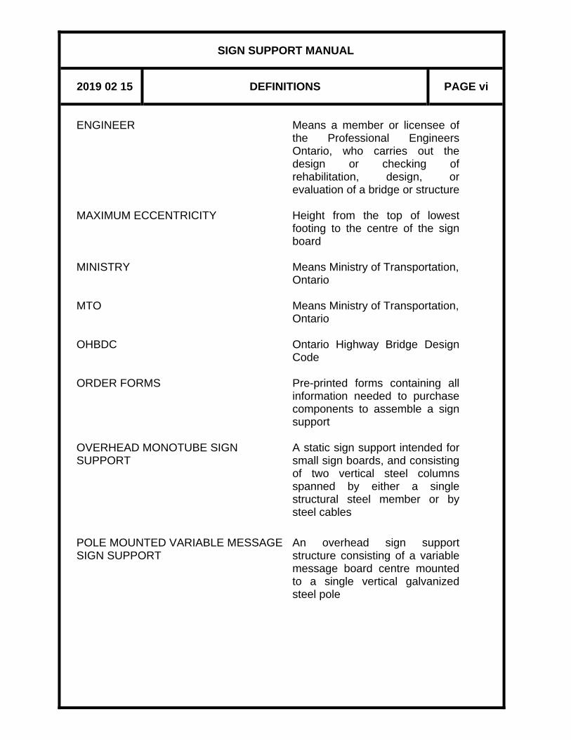
ENGINEER
Means a member or licensee of the Professional Engineers Ontario, who carries out the design or checking of rehabilitation, design, or evaluation of a bridge or structure
MAXIMUM ECCENTRICITY MINISTRY
Height from the top of lowest footing to the centre of the sign board Means Ministry of Transportation, Ontario
MTO Means Ministry of Transportation,
Ontario OHBDC Ontario Highway Bridge Design
Code ORDER FORMS Pre-printed forms containing all
information needed to purchase components to assemble a sign support
OVERHEAD MONOTUBE SIGN SUPPORT
A static sign support intended for small sign boards, and consisting of two vertical steel columns spanned by either a single structural steel member or by steel cables
POLE MOUNTED VARIABLE MESSAGE SIGN SUPPORT
An overhead sign support structure consisting of a variable message board centre mounted to a single vertical galvanized steel pole

SIGN SUPPORT MANUAL
2019 02 15 DEFINITIONS PAGE vii
SIGN SUPPORT SITE NUMBER
A structure to support static signs (sign boards) or variable message sign systems Number assigned to a sign support structure by the Region, to provide a unique identifier for each sign structure
STANDARD DRAWING A structural drawing as shown on the hardcopies distributed with this Manual. It is available as an electronic CAD file requiring the user to add site specific information
STATIC SIGN (OR SIGN BOARD)
A flat surface displaying permanent visual information
TRI-CHORD STATIC SIGN SUPPORT
A static sign support structure consisting of a galvanized steel overhead truss constructed in the form of a three chord system and having prismatic vertical legs
VARIABLE MESSAGE SIGN (VMS)
Light emitting electronic display system that changes periodically to provide up-to-date information to freeway motorists of traffic conditions ahead, and suggests alternative routing in a timely and safe manner
VARIABLE MESSAGE SIGN SUPPORT
A sign support for variable message sign systems, consisting of two vertical supports or legs (structural steel), and an overhead truss (aluminium)

SIGN SUPPORT MANUAL
2019 02 15 DEFINITIONS PAGE viii
WALKWAY A permanent platform provided
on some sign support structures at the level of the sign board(s), facilitating ease of installation and maintenance of the sign board(s)

SIGN SUPPORT MANUAL
2019 02 15 NOTATION PAGE ix
A spacing of sign support posts, or length of stiffener, or outside diameter of sign support post. B width of sign board, or depth of stiffener,or length of panel in VMS end components. CS horizontal centroidal axis of sign board. D height of sign board E horizontal distance from left support to leftmost sign board, or horizontal distance from the centreline of the sign support post to the centre of the sign board, or horizontal distance from the centreline of the sign support leg to the centreline of the end vertical element of the sign component. EL.CS elevation of CS. EL.EP elevation of EP. EL.HP elevation of the highest point on the highway under the sign, including shoulders, curbs, and medians. EL.Pi elevation at top of footing Pi. EP edge of pavement of travelled portion of highway.
F horizontal distance from left support to 2nd leftmost sign board. G perpendicular distance from edge of pavement to first column, or horizontal distance from left support to 3rd leftmost sign board, or horizontal distance from rear face of traffic barrier to the nearest face of support structure footing. H lateral sign overhang beyond end T, or horizontal distance from left support to 4th leftmost sign board, or dimension from centreline of bottom chord to the highest point on the highway for simply supported tri-chord Hi vertical distance from Pi to CS. Hmax maximum Hi. J edge distance of 2nd lowest bolt group from bottom of member, or horizontal distance from edge of sign board to outside T connector, or horizontal distance from left support to splice location.

SIGN SUPPORT MANUAL
2019 02 15 NOTATION PAGE x
K horizontal distance from edge of sign board to inside T connector, or horizontal distance from right support to splice location, or
a dimension used to impose a camber on cantilever sign supports to allow for dead load deflections.
L length of column Lx distance of Z-bracket from the end of sign board closest to traffic Pi top of footing. SLS Serviceability Limit States, as defined in The Canadian Highway Bridge Design
Code. ULS Ultimate Limit States, as defined in The Canadian Highway Bridge Design
Code. VMS Variable Message Sign X horizontal distance from left footing to control line. Y horizontal distance from right footing to control line.

SIGN SUPPORT MANUAL
SECTION 1 – INTRODUCTION
February 2019

SIGN SUPPORT MANUAL
2019 02 15 INTRODUCTION PAGE 1 - 1
1 INTRODUCTION
1.1 GENERAL
The Sign Support Manual has been prepared to assist ministry offices, or others, in procuring and erecting all types of sign supports and for preparing the contract documents.
1.2 SECTIONS The Manual contains the following sections: Section 1 Introduction Section 2 General Information Section 3 Cantilever Static Sign Supports Section 4 Tri-Chord Static Sign Supports Section 5 Steel Column Sign Supports
(This section has been removed from the Manual) Section 6 Timber Post Sign Supports
(This section has been removed from the Manual) Section 7 Overhead Monotube Sign Supports Section 8 Variable Message Sign Supports Section 9 Bridge Mounted Sign Supports The sections of this Manual are self-contained and may be issued and revised at different times.
1.3 NUMBERING SYSTEM Each section is numbered as shown above. Within the sections, the material is further subdivided into sub-sections, numbered decimally. Reduced copies of standard drawings, which are included in the Manual to explain their use, carry their original numbers and, in some cases, Figure numbers relating to the Manual numbering system. Such drawings also carry their latest revision dates at the time of their preparation.
1.4 REVISIONS When additions or revisions are necessary, they will be made available through the web site, as detailed in Section 1.6.
SIGN SUPPORT MANUAL
2019 02 15 INTRODUCTION PAGE 1 - 2
1.5 METRICATION
The supports covered by Section 9 are primarily fabricated from aluminum extruded members which have not been metricated at this time. Thus, supports in this section are detailed in soft converted metric units except as for the drawings detailing the chord clamp, the service walk grating, and the two-post railing, which are detailed in imperial units. All dimensions are in millimetres unless otherwise stated.
1.6 DISTRIBUTION Digital copy of the Manual and revisions may be obtained from: http://www.raqs.mto.gov.on.ca/techpubs/ops.nsf/OPSHomepage
1.7 STANDARD DRAWINGS Electronic CAD files containing standard drawings in AutoCAD may be obtained from the CPS.

SIGN SUPPORT MANUAL
SECTION 2 – GENERAL INFORMATION
February 2019

SIGN SUPPORT MANUAL
2019 02 15 GENERAL INFORMATION PAGE 2 - 1
2 GENERAL INFORMATION 2.1 SCOPE
This Manual contains information needed to prepare the contract drawings, tender quantities, and special provisions for sign supports covered in Sections 3, 4, 7, 8 and 9.
2.2 STANDARD SIGN SUPPORTS
Only standard sign supports are described in this Manual and listed within their respective sections. All non-standard sign supports must be custom designed. Overhead truss sign supports (Type 1) previously covered in this Manual have been withdrawn and replaced by Tri-chord static sign supports. Steel column and timber post sign supports previously covered in this Manual have been removed.
2.3 ASSUMPTIONS, CRITERIA AND LIMITATIONS
Design code assumptions, criteria, and limitations for each sign support type is described in the respective sections of this Manual. Drawings and special provisions for Tri-chord, Cantilever, Monotube, and Variable Message sign supports are sufficiently standardized that Regional Structural Section staff or others may process them. Bridge mounted sign supports must be designed to suit the geometry of the bridge by the Regional Structural Sections or others.
2.4 STANDARD DRAWINGS 2.4.1 INFORMATION TO BE ADDED TO STANDARD DRAWINGS
Standard drawings shall be reviewed together with the corresponding text in the Manual to determine what information, if any, needs to be added to them. Where information in tables and dimensions are added to standard drawings for their completion, the drawings shall bear the seal, date and signature of a Professional Engineer. This Engineer accepts full responsibility for the accuracy of the added information only. Where engineering design changes are made on standard drawings that affect the original design, these drawings shall be identified as
SIGN SUPPORT MANUAL
2019 02 15 GENERAL INFORMATION PAGE 2 - 2
“Modified” and bear the seals, dates, and signatures of two Professional Engineers. These Engineers accept full responsibility for the design that results from these changes.
2.4.2 SCALES FOR ADDED DETAILS Plan views should normally be drawn at 1:50 scale. Details should be drawn to a sufficiently large scale to ensure legibility after reduction to contract book size.
2.5 PROCESSING OF DOCUMENTS
2.5.1 PREPARATION OF ELECTRICAL DRAWINGS In general, supplementary illumination is not required for static signs because of the reflective ability of sign facing materials and, in some cases, the impact of roadway lighting. Regional Traffic Section determines when sites require illumination. If the sign is to be illuminated, then two copies of the General Arrangement drawing are required to be sent to regional electrical design staff. They will arrange for the preparation of the electrical drawings if they are required. For the Variable Message Signs (VMS), the Advanced Traffic Management Section should be consulted.
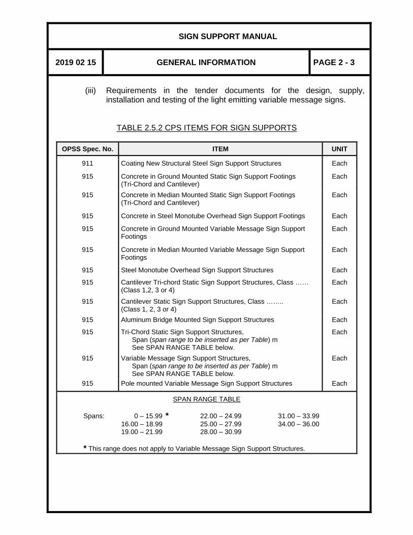
2.5.2 CONTRACT PREPARATION SYSTEM Capital construction contract tender documents are produced for the ministry by using the Contract Preparation System (CPS). This is an integrated application facility for the preparation of tender item documents, item quantity sheets, modified and fill-in special provisions, etc., for road design, structural, and electrical work. Whenever sign supports are to be supplied and erected as (part of) a contract, applicable tender documents shall be prepared and forwarded to the Regional Planning and Design Office with a covering transmittal letter. The tender items to be used, where applicable, for sign support footings and sign support structures are as shown in Table 2.5.2. The accompanying transmittal letter shall instruct Regional Planning and Design to complete the following items: (i) Traffic Control (ii) Supply and erect sign board, for static sign supports
SIGN SUPPORT MANUAL
2019 02 15 GENERAL INFORMATION PAGE 2 - 3
(iii) Requirements in the tender documents for the design, supply,
installation and testing of the light emitting variable message signs.
TABLE 2.5.2 CPS ITEMS FOR SIGN SUPPORTS
OPSS Spec. No. ITEM UNIT
911 Coating New Structural Steel Sign Support Structures Each
915 Concrete in Ground Mounted Static Sign Support Footings (Tri-Chord and Cantilever)
Each
915 Concrete in Median Mounted Static Sign Support Footings (Tri-Chord and Cantilever)
Each
915 Concrete in Steel Monotube Overhead Sign Support Footings Each
915 Concrete in Ground Mounted Variable Message Sign Support Footings
Each
915 Concrete in Median Mounted Variable Message Sign Support Footings
Each
915 Steel Monotube Overhead Sign Support Structures Each
915 Cantilever Tri-chord Static Sign Support Structures, Class …… (Class 1,2, 3 or 4)
Each
915 Cantilever Static Sign Support Structures, Class …….. (Class 1, 2, 3 or 4)
Each
915 Aluminum Bridge Mounted Sign Support Structures Each
915 Tri-Chord Static Sign Support Structures, Span (span range to be inserted as per Table) m See SPAN RANGE TABLE below.
Each
915 Variable Message Sign Support Structures, Span (span range to be inserted as per Table) m See SPAN RANGE TABLE below.
Each
915 Pole mounted Variable Message Sign Support Structures Each
SPAN RANGE TABLE
Spans: 0 – 15.99 * 22.00 – 24.99 31.00 – 33.99 16.00 – 18.99 25.00 – 27.99 34.00 – 36.00 19.00 – 21.99 28.00 – 30.99
* This range does not apply to Variable Message Sign Support Structures.

SIGN SUPPORT MANUAL
2019 02 15 GENERAL INFORMATION PAGE 2 - 4
2.5.3 DISTRIBUTION OF COMPLETED DRAWINGS AND CONTRACT
DOCUMENTS
Copies of the completed drawings and applicable contract documents shall be distributed as follows: REGIONAL PLANNING AND DESIGN (Manager) - 2 copies (Northwestern Region has requested two additional copies). ESTIMATING OFFICE (Manager) - 1 copy For the preparation of the cost estimate. REGIONAL CONSTRUCTION STAFF (District Engineer) - 1 copy To make provision for the supply and erection of the sign and to alert District staff of future sign locations.
2.6 TRAFFIC PROTECTION
Columns of non-breakaway sign supports, Monotube sign supports, Tri-chord, VMS, and Cantilever sign supports must be protected from traffic travelling the adjacent roadways. Protection must be provided in the form of guiderail, barrier wall, a retaining wall or some similar feature having at least as much stiffness and strength as a guiderail and presenting a smooth face to traffic.
2.7 SOIL CONDITIONS
Footing proportions provided in this Manual are intended to apply to normal soil conditions; that is, competent soils of uniform composition. Site foundation conditions requiring special design consideration include: - bedrock is at or near the surface - footing is located in rock fill - soil is exceptionally soft or loose.

SIGN SUPPORT MANUAL
2019 02 15 GENERAL INFORMATION PAGE 2 - 5
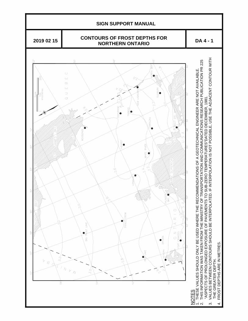
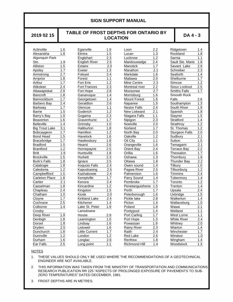
2.8 FROST DEPTH
Frost layer depths for a specific site location may be obtained from Design Aids DA4-1, DA4-2 and DA4-3. Contours of frost depth for Northern Ontario, Southern Ontario, and List of Towns, respectively, are given in the Appendix of this Section. These values may be used if the recommendations of a geotechnical engineer are not available.
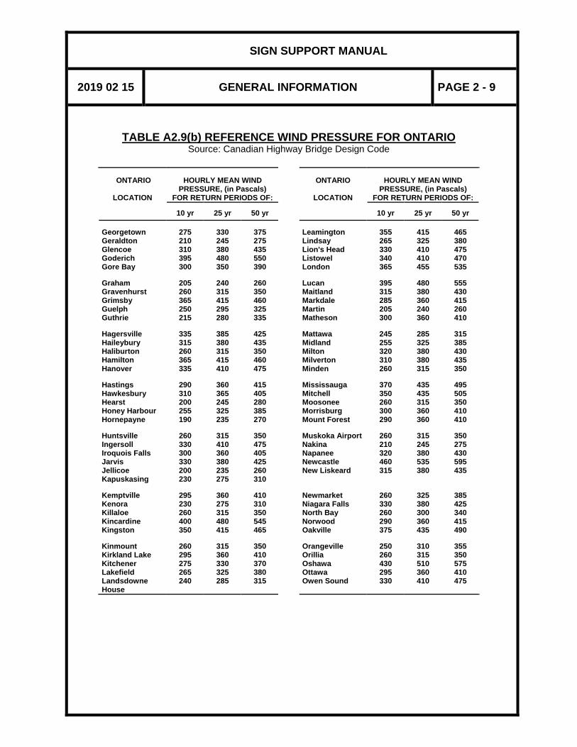
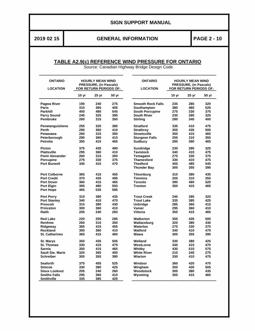
2.9 REFERENCE WIND PRESSURE
Values for the local reference wind pressure can be obtained from the Tables A2.9(a) to (c) given in the Appendix of this Section. The information shown in these tables were obtained from the CHBDC.
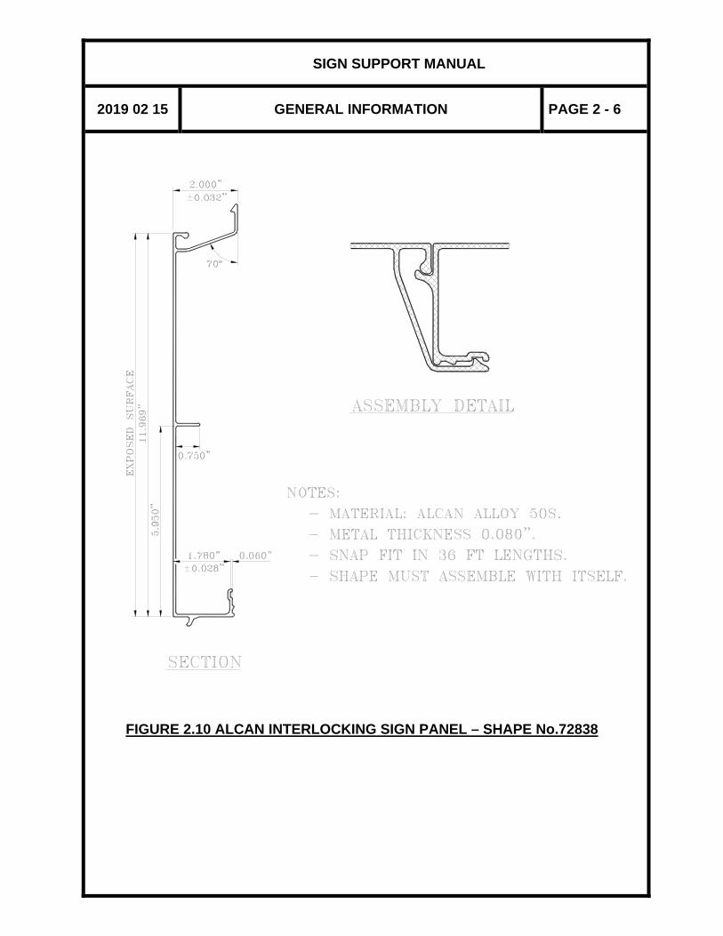
2.10 SIGN BOARDS All static sign support designs are based on the aluminum Alcan Interlocking Sign Panel, Shape No. 72838, as shown in Figure 2.10. Alcan standard extrusion tolerances and finishes will apply unless otherwise specified.
2.11 VARIABLE MESSAGE SYSTEMS
The requirements for the design, supply, installation, and testing of Light Emitting Variable Message Signs (VMS) are covered by the associated Special Provisions. The major features of the variable message sign shall consist of: sign case and face, display matrix, driving electronics, photo sensor control, environmental control and protection, mounting hardware, and associated cables and wiring.
SIGN SUPPORT MANUAL
2019 02 15 GENERAL INFORMATION PAGE 2 - 6
FIGURE 2.10 ALCAN INTERLOCKING SIGN PANEL – SHAPE No.72838
SIGN SUPPORT MANUAL
2019 02 15 GENERAL INFORMATION PAGE 2 - 7
APPENDIX TO SECTION 2
GENERAL INFORMATION
TABLES A2.9 REFERENCE WIND PRESSURE FOR ONTARIO (a), (b) and (c) DA4-1 CONTOURS OF FROST DEPTHS FOR NORTHERN ONTARIO DA4-2 CONTOURS OF FROST DEPTHS FOR SOUTHERN ONTARIO DA4-3 TABLE OF FROST DEPTHS FOR ONTARIO BY LOCATION

SIGN SUPPORT MANUAL
2019 02 15 GENERAL INFORMATION PAGE 2 - 8
TABLE A2.9(a) REFERENCE WIND PRESSURE FOR ONTARIO
Source: Canadian Highway Bridge Design Code
ONTARIO
LOCATION
HOURLY MEAN WIND
PRESSURE, (in Pascals) FOR RETURN PERIODS OF:
ONTARIO
LOCATION
HOURLY MEAN WIND PRESSURE, (in Pascals)
FOR RETURN PERIODS OF:
10 yr
25 yr 50 yr
10 yr
25 yr
50 yr Ailsa Craig Ajax Alexandria Alliston Almonte
395 430 305 220 295
480 510 360 280 360
550 570 400 330 410
Chatham Chelmsford Chesley Clinton Coboconk
320 285 330 375 260
380 375 410 455 315
430 450 475 525 350
Ansonville Armstrong Arnprior Atikokan Aurora
305 205 275 200 305
360 240 330 235 380
400 260 370 260 440
Cobourg Cochrane Colborne Collingwood Cornwall
465 260 440 255 300
535 310 510 325 360
595 350 565 385 410
Bancroft Barrie Barriefield Beaverton Belleville
230 210 350 240 320
280 280 415 305 380
320 330 460 360 430
Corunna Deep River Deseronto Dorchester Dorion
350 260 320 330 300
415 315 380 410 355
465 350 430 480 390
Belmont Bowmanville Bracebridge Bradford Brampton
350 460 260 240 315
435 535 315 305 380
500 590 350 360 430
Dresden Dryden Dunbarton Dunnville Durham
320 200 430 335 310
380 235 510 385 380
430 260 575 425 435
Brantford Brighton Brockville Brooklin Burk's Falls
310 415 315 385 260
365 485 380 460 315
400 540 430 520 350
Dutton Earlton Edison Elmvale Embro
340 315 230 235 330
410 390 275 305 410
470 450 310 365 475
Burlington Caledonia Cambridge Campbellford Camp Borden
360 315 265 290 215
415 365 310 360 280
460 400 350 415 335
Englehart Espanola Exerter Fenelon Falls Fergus
290 280 375 250 260
360 360 455 310 310
415 420 525 355 355
Cannington Carleton Place Cavan Centralia Chapleau
245 295 310 375 190
310 360 380 455 235
360 410 435 525 270
Fonthill Forest Fort Erie Fort Frances Gananoque
335 390 365 230 350
385 460 415 275 415
425 520 460 310 465
SIGN SUPPORT MANUAL
2019 02 15 GENERAL INFORMATION PAGE 2 - 9
TABLE A2.9(b) REFERENCE WIND PRESSURE FOR ONTARIO Source: Canadian Highway Bridge Design Code
ONTARIO
LOCATION
HOURLY MEAN WIND
PRESSURE, (in Pascals) FOR RETURN PERIODS OF:
ONTARIO
LOCATION
HOURLY MEAN WIND PRESSURE, (in Pascals)
FOR RETURN PERIODS OF:
10 yr
25 yr 50 yr
10 yr
25 yr
50 yr Georgetown Geraldton Glencoe Goderich Gore Bay
275 210 310 395 300
330 245 380 480 350
375 275 435 550 390
Leamington Lindsay Lion's Head Listowel London
355 265 330 340 365
415 325 410 410 455
465 380 475 470 535
Graham Gravenhurst Grimsby Guelph Guthrie
205 260 365 250 215
240 315 415 295 280
260 350 460 325 335
Lucan Maitland Markdale Martin Matheson
395 315 285 205 300
480 380 360 240 360
555 430 415 260 410
Hagersville Haileybury Haliburton Hamilton Hanover
335 315 260 365 335
385 380 315 415 410
425 435 350 460 475
Mattawa Midland Milton Milverton Minden
245 255 320 310 260
285 325 380 380 315
315 385 430 435 350
Hastings Hawkesbury Hearst Honey Harbour Hornepayne
290 310 200 255 190
360 365 245 325 235
415 405 280 385 270
Mississauga Mitchell Moosonee Morrisburg Mount Forest
370 350 260 300 290
435 435 315 360 360
495 505 350 410 410
Huntsville Ingersoll Iroquois Falls Jarvis Jellicoe Kapuskasing
260 330 300 330 200 230
315 410 360 380 235 275
350 475 405 425 260 310
Muskoka Airport Nakina Napanee Newcastle New Liskeard
260 210 320 460 315
315 245 380 535 380
350 275 430 595 435
Kemptville Kenora Killaloe Kincardine Kingston
295 230 260 400 350
360 275 315 480 415
410 310 350 545 465
Newmarket Niagara Falls North Bay Norwood Oakville
260 330 260 290 375
325 380 300 360 435
385 425 340 415 490
Kinmount Kirkland Lake Kitchener Lakefield Landsdowne House
260 295 275 265 240
315 360 330 325 285
350 410 370 380 315
Orangeville Orillia Oshawa Ottawa Owen Sound
250 260 430 295 330
310 315 510 360 410
355 350 575 410 475
SIGN SUPPORT MANUAL
2019 02 15 GENERAL INFORMATION PAGE 2 - 10
TABLE A2.9(c) REFERENCE WIND PRESSURE FOR ONTARIO Source: Canadian Highway Bridge Design Code
ONTARIO
LOCATION
HOURLY MEAN WIND
PRESSURE, (in Pascals) FOR RETURN PERIODS OF:
ONTARIO
LOCATION
HOURLY MEAN WIND PRESSURE, (in Pascals)
FOR RETURN PERIODS OF:
10 yr
25 yr 50 yr
10 yr
25 yr
50 yr Pagwa River Paris Parkhill Parry Sound Pembroke
190 310 400 245 260
240 365 480 325 315
275 405 545 395 350
Smooth Rock Falls Southampton South Porcupine South River Stirling
235 380 275 230 280
285 460 330 280 345
320 525 375 325 400
Penetanguishene Perth Petawawa Peterborough Petrolia
255 295 260 290 350
325 360 315 360 415
385 410 350 415 465
Stratford Strathroy Streetsville Sturgeon Falls Sudbury
335 355 350 255 290
410 435 415 310 390
475 500 465 355 465
Picton Plattsville Point Alexander Porcupine Port Burwell
375 295 260 275 345
435 360 315 330 415
490 410 350 375 470
Sundridge Tavistock Temagami Thamesford Thedford Thunder Bay
230 340 275 330 405 300
280 410 330 410 485 355
325 475 375 475 545 390
Port Colborne Port Credit Port Dover Port Elgin Port Hope
365 370 360 395 465
415 435 415 480 535
455 495 465 550 595
Tilsonburg Timmins Toronto Trenton
310 255 390 350
380 310 460 415
435 355 520 465
Port Perry Port Stanley Prescott Princeton Raith
310 340 315 300 205
380 410 380 360 240
435 470 430 410 260
Trout Creek Trout Lake Uxbridge Vanier Vittoria
240 335 285 295 355
285 385 360 360 415
320 425 415 410 465
Red Lake Renfrew Ridgeway Rockland St. Catharines
220 260 365 300 365
255 310 415 360 415
285 350 455 410 460
Walkerton Wallaceburg Waterloo Watford Wawa
355 320 275 340 300
435 380 330 410 355
500 430 370 470 390
St. Marys St. Thomas Sarnia Sault Ste. Marie Schreiber
350 330 350 320 300
435 410 415 365 355
505 475 465 400 390
Welland WestLorne Whitby White River Wiarton
330 345 430 210 330
380 415 510 245 410
425 470 575 275 475
Seaforth Simcoe Sioux Lookout Smiths Falls Smithville
375 330 205 295 335
455 380 240 360 385
525 425 260 410 425
Windsor Wingham Woodstock Wyoming
360 350 305 350
420 435 380 415
470 505 435 465
SIGN SUPPORT MANUAL
2019 02 15 CONTOURS OF FROST DEPTHS FOR NORTHERN ONTARIO DA 4 - 1
NO
TES
1.
TH
ES
E V
ALU
ES
SH
OU
LD O
NLY
BE
US
ED
WH
ER
E T
HE
RE
CO
MM
EN
DA
TIO
NS
OF
A G
EO
TEC
HN
ICA
L E
NG
INE
ER
AR
E N
OT
AV
AIL
AB
LE.
2. T
HIS
INFO
RM
ATI
ON
WAS
TA
KE
N F
RO
M T
HE
MIN
ISTR
Y O
F TR
AN
SPO
RTA
TIO
N A
ND
CO
MM
UN
ICA
TIO
NS
RE
SE
AR
CH
PU
BLI
CA
TIO
N P
R 2
25
“AS
PE
CTS
OF
PR
OLO
NG
ED
EX
PO
SU
RE
OF
PA
VEM
EN
TS T
O S
UB
-ZE
RO
TEM
PE
RA
TUR
ES
”DA
TED
DE
CE
MB
ER
, 198
1.
3. V
ALU
ES
BE
TWE
EN
CO
NTO
UR
S S
HO
ULD
BE
INTE
RP
OLA
TED
. IF
INTE
RP
OLA
TIO
N IS
NO
T PO
SS
IBLE
, US
E T
HE
AD
JAC
EN
T C
ON
TOU
R W
ITH
TH
E G
RE
ATE
R D
EP
TH.
4. F
RO
ST
DE
PTH
S A
RE
IN M
ETR
ES
.

SIGN SUPPORT MANUAL
2019 02 15 CONTOURS OF FROST DEPTHS FOR SOUTHERN ONTARIO DA 4 - 2
NO
TES
1.
TH
ES
E V
ALU
ES
SH
OU
LD O
NLY
BE
US
ED
WH
ER
E T
HE
RE
CO
MM
EN
DA
TIO
NS
OF
A G
EO
TEC
HN
ICA
L E
NG
INE
ER
AR
E N
OT
AV
AIL
AB
LE.
2. T
HIS
INFO
RM
ATI
ON
WAS
TA
KE
N F
RO
M T
HE
MIN
ISTR
Y O
F TR
AN
SPO
RTA
TIO
N A
ND
CO
MM
UN
ICA
TIO
NS
RE
SE
AR
CH
PU
BLI
CA
TIO
N P
R 2
25
“AS
PE
CTS
OF
PR
OLO
NG
ED
EX
PO
SU
RE
OF
PA
VEM
EN
TS T
O S
UB
-ZE
RO
TEM
PE
RA
TUR
ES
”DA
TED
DE
CE
MB
ER
, 198
1.
3. V
ALU
ES
BE
TWE
EN
CO
NTO
UR
S S
HO
ULD
BE
INTE
RP
OLA
TED
. IF
INTE
RP
OLA
TIO
N IS
NO
T PO
SS
IBLE
, US
E T
HE
AD
JAC
EN
T C
ON
TOU
R W
ITH
TH
E G
RE
ATE
R D
EP
TH.
4. F
RO
ST
DE
PTH
S A
RE
IN M
ETR
ES
.
SIGN SUPPORT MANUAL
2019 02 15 TABLE OF FROST DEPTHS FOR ONTARIO BY LOCATION DA 4 - 3
Actinolite 1.6 Eganville 1.9 Loon 2.2 Ridgetown 1.4Alexandria 1.8 Elmira 1.5 Lucan 1.3 Rockland 1.8Algonquin Park Englehart 2.3 Lucknow 1.2 Sarnia 1.1 Stn. 1.9 English River 2.5 Manitouwadge 2.4 Sault Ste. Marie 1.8Alliston 1.5 Estaire 2.0 Manotick 1.7 Savant Lake 2.6Apsley 1.7 Exeter 1.3 Marathon 2.1 Schreiber 2.3Armstrong 2.7 Foleyet 2.4 Markdale 1.6 Seaforth 1.4Arnprior 1.8 Forest 1.1 Mattawa 2.0 Shelburne 1.7Arthur 1.7 Fort Erie 1.2 Mine Centre 2.3 Simcoe 1.2Atikokan 2.4 Fort Frances 2.3 Montreal river 2.2 Sioux Lookout 2.5Attawapiskat 2.9 Fort Hope 2.8 Moosonee 2.7 Smiths Falls 1.7Bancroft 1.8 Gananoque 1.4 Morrisburg 1.6 Smooth Rock Bannockburn 1.7 Georgetown 1.4 Mount Forest 1.6 Falls 2.6Barbers Bay 2.4 Geraldton 2.6 Napanee 1.5 Southampton 1.3Barkway 1.7 Glencoe 1.1 Nestor Falls 2.4 South River 1.9Barrie 1.5 Goderich 1.2 New Liskeard 2.1 Spanish 1.8Barry’s Bay 1.9 Gogama 2.3 Niagara Falls 1.1 Stayner 1.5Beaverton 1.6 Gravenhurst 1.7 Nipigon 2.3 Stratford 1.4Belleville 1.4 Grimsby 1.0 Noelville 2.0 Strathroy 1.2Big Trout Lake 3.1 Haliburton 1.8 Norland 1.7 St. Thomas 1.2Bobcaygeon 1.7 Hamilton 1.2 North Bay 2.0 Sturgeon Falls 2.0Bond Head 1.5 Havelock 1.6 Oakville 1.2 Sudbury 2.1Bracebridge 1.7 Hawkesbury 1.8 Oil City 1.1 Sutton 1.5Bradford 1.5 Hearst 2.6 Orangeville 1.6 Temagami 2.1Brantford 1.2 Hornepayne 2.5 Orient Bay 2.4 Terrace Bay 2.2Britt 1.9 Huntsville 1.8 Orillia 1.6 Thessalon 1.7Brockville 1.5 Hurkett 2.3 Oshawa 1.3 Thornbury 1.6Burk’s Falls 1.8 Ignace 2.5 Ottawa 1.8 Thunder Bay 2.2Calabogie 1.8 Iroquois Falls 2.4 Owen sound 1.4 Tilbury 1.0Caledonia 1.2 Kapuskasing 2.5 Pagwa River 2.5 Tillsonburg 1.2Campbellford 1.5 Kashabowie 2.4 Palmerston 1.6 Timmins 2.4Carleton Place 1.8 Kemptville 1.7 Parry Sound 1.4 Tobermory 1.4Cartier 2.1 Kenora 2.4 Pembroke 1.7 Toronto 1.2Casselman 1.8 Kincardine 1.2 Penetanguishene 1.5 Trenton 1.4Chapleau 2.4 Kingston 1.5 Perth 1.7 Upsala 2.4Chatham 1.0 Kiosk 2.0 Peterborough 1.6 Uxbridge 1.5Cloyne 1.7 Kirkland Lake 2.4 Pickle lake 2.8 Walkerton 1.4Cochrane 2.5 Kitchener 1.4 Picton 1.4 Wallaceburg 1.0Colborne 1.4 Lake St. Peter 1.9 Poland 1.8 Wawa 2.1Crosby Lansdowne Pontypool 1.4 Welland 1.1Deep River 1.9 House 2.9 Port Carling 1.7 West Lorne 1.1Denbigh 1.8 Leamington 1.0 Port Hope 1.3 White River 2.4Dorset 1.8 Lindsay 1.6 Powassan 1.9 Whitney 2.0Dryden 2.5 Listowel 1.6 Rainy River 2.3 Wiarton 1.4Dunchurch 1.8 Little Current 1.7 Raith 2.4 Winchester 1.7Dunnville 1.2 London 1.2 Red Lake 2.6 Windsor 1.0Durham 1.6 Longlac 2.6 Renfrew 1.8 Wingham 1.4Ear Falls 2.5 Long point 1.1 Richmond Hill 1.4 Woodstock 1.3
NOTES
1. THESE VALUES SHOULD ONLY BE USED WHERE THE RECOMMENDATIONS OF A GEOTECHNICAL ENGINEER ARE NOT AVAILABLE.
2. THIS INFORMATION WAS TAKEN FROM THE MINISTRY OF TRANSPORTATION AND COMMUNICATIONS RESEARCH PUBLICATION RR 225 “ASPECTS OF PROLONGED EXPOSURE OF PAVEMENTS TO SUB-ZERO TEMPERATURES” DATED DECEMBER, 1981.
3. FROST DEPTHS ARE IN METRES.

This page is intentionally left blank
SIGN SUPPORT MANUAL
SECTION 3 – CANTILEVER STATIC SIGN SUPPORTS
February 2019

SIGN SUPPORT MANUAL
2019 02 15 CANTILEVER STATIC SIGN SUPPORTS PAGE 3 - 1
3 CANTILEVER STATIC SIGN SUPPORTS 3.1 GENERAL 3.1.1 TYPES OF SIGN SUPPORTS
There are three types of cantilever sign supports: Single Cantilever: one sign, mounted to one side of the vertical
support member, Figure 3.1.2(a) (see Standard Drawings SS118-24 and SS118-73)
Butterfly (Double two signs, each mounted on opposite sides Cantilever): of the "T" style support, Figure 3.1.2(b).
(see Standard Drawings SS118-22 and SS118-71) Centre Mounted: one sign, mounted over the vertical support member,
Figure 3.1.2(c). No standard is currently available. 3.1.2 STANDARD SIGN SUPPORTS
Standard cantilever sign supports are designed to support static sign boards. The sign supports are fabricated in structural steel and designed to the requirements of the CAN/CSA-S6-06(CHBDC). The sign supports contained in this Section are designed for sign boards and site conditions that meet the following criteria: (a) Maximum sign board area and eccentricity limits based on Figures
3.2.2(a) to (h) (b) For the butterfly sign support, the maximum sign area is the total area
of both sides. The sign area of one side shall not be greater than two times that of the other side
(c) Depth of sign board up to 2745 mm (9 ft.) (d) All sign boards include an aerodynamic damper attachment (see
Figure 3.3.2 and Appendix) (e) Reference wind pressure up to 600 Pa for a return period of 50 years.
The effect of wind funnelling due to special topographical features such as deep valleys is not considered (CHBDC 3.10.1.2)
(f) Location of supports and vertical clearances according to the
requirements of the CHBDC and MTO Design Supplement for TAC Geometric Design Guide for Canadian Roads (2017)
(g) Competent soil conditions (as described in Section 3.5.4) excluding
rock fill.

SIGN SUPPORT MANUAL
2019 02 15 CANTILEVER STATIC SIGN SUPPORTS PAGE 3 - 2
FIGURE 3.1.2(a) SINGLE CANTILEVER SIGN SUPPORT
FIGURE 3.1.2(b) BUTTERFLY SIGN SUPPORT
FIGURE 3.1.2(c) CENTRE MOUNTED SIGN SUPPORT Note: All three types can also be mounted on a barrier wall.
SIGN SUPPORT MANUAL
2019 02 15 CANTILEVER STATIC SIGN SUPPORTS PAGE 3 - 3
3.1.3 LIMITATIONS
For economic and practical reasons, these supports should be placed as close as possible to the edge of the travelled portion of the highway (see Section 3.1.6). Therefore, these supports will probably be in the Clear Recovery Zone and should be protected as discussed in Section 2.6. For ground mounted footings, the top of footing elevation shall be a minimum of 300 mm above the finished grade. This could be increased up to 1000 mm in order to limit the leg height. The dimension from the top of the footing to the centreline of the bottom arm shall not exceed 6500 mm. Therefore, the total height from grade to centreline of the bottom arm cannot exceed 7500 mm.
3.1.4 CANTILEVER SIGN SUPPORTS
Cantilever sign supports are fabricated from structural steel and are designed for ground mounting or on concrete median barriers. The typical layout plan and sign support elevation are shown in Figures 3.1.4 (a) through (d). The vertical support member is straight and made from round or octagonal shape sections. Fabricators may choose to fabricate the octagonal shape from steel plate. Octagonal sections have to meet the requirements shown on Standard Drawings SS118-22, SS118-24, SS118-71 and SS118-73. The maximum allowable length of the vertical support member is 8500 mm, which is a limit imposed by design. It is connected at the base to a concrete footing by a bolted anchorage system. The horizontal arms are circular HSS sections inter-connected by verticals and diagonals. These vertical and diagonal members are fabricated from either circular HSS sections with welded connection, or double angles with bolted connection. Sign boards are centered vertically between the horizontal arms, and are attached to these members by means of Z-brackets (see Figure A3.1). The horizontal arms are connected to the vertical support member by a bolted flange welded to the support. For butterfly sign supports, horizontal arms shall be located at the same elevation and extend in both directions. An aerodynamic damper along the full width of all sign boards is required to suppress vortex shedding and galloping instabilities of the structure under various wind conditions. The damper is attached to each Z-bracket by means of stainless steel bolts. The damper assembly is fabricated from structural aluminum, and is comprised of a damper plate, gusset plates, and support angles (see Figure 3.3.2). All structural steel components are galvanized after fabrication. The support leg is subsequently coated with an approved paint system.

SIGN SUPPORT MANUAL
2019 02 15 CANTILEVER STATIC SIGN SUPPORTS PAGE 3 - 4
3.1.5 FOOTINGS
Each sign support footing consists of a reinforced concrete caisson. Details differ according to their location, and generally are of two types, as shown on the standard drawings: ground mounted and median mounted signs (see Standard Drawings SS118-3, SS118-4, and SS118-5). The indicated footing depths are the minimum required for each support. Footing proportions assume competent soil conditions of uniform composition. Parameters upon which the design is based are given in Section 3.5.4. Encountered soil conditions such as rock fill, land fill, and soft material are not covered here, and require the footing to be designed by an Engineer.
3.1.6 CLEARANCE
For ground mounted footings, the minimum horizontal clearance ‘G’ from the back of traffic protection barrier to the nearest face of sign support footing shall not be less than the values specified in Figure A3.2 (see Appendix to Section 3). The minimum vertical distance from the highest point on the highway, including shoulders, curbs, and medians to the bottom of the deepest sign board (2745 mm) shall not be less than 5300 mm. The minimum vertical clearance from the highest point on the highway including shoulders, curbs, and medians to the bottom of the lower chord shall not be less than 5600 mm. Small lane designation sign boards with limited strength connections are allowed to project below the bottom edge of a sign board as long as damage to them does not cause damage to the structure or present a hazard to traffic below (see Figure A4.2).

SIGN SUPPORT MANUAL
2019 02 15 CANTILEVER STATIC SIGN SUPPORTS PAGE 3 - 5
3.1.7 DETERMINING ARM LENGTH AND PANEL LENGTHS The length of the arms shall extend to 50 mm from the end of the sign. The number and spacing of the panels shall be based on the following criteria (this shall be calculated on both sides for butterfly sign supports): (1) A minimum of 2 panels (if it is calculated that only one panel is
required, the arms shall be fabricated without verticals/diagonals and installed individually).
(2) A maximum panel spacing of 2600 mm. (3) An equal panel length spacing except as modified in (4) below (4) The size of the panel nearest to the leg may be adjusted if there is a
conflict between the Z-bracket nearest to a leg and the panel point gusset plate (see also Section 3.1.8).
See Section 3.2.3 and 3.2.4 for examples.
3.1.8 DETERMINING THE LOCATION OF Z-BRACKETS
The number and spacing of Z-brackets for the attachment of the sign board to the structure shall be based on the following criteria (this shall be calculated on both sides for butterfly sign supports): (1) Maximum spacing of 1500 mm. (2) The number of Z-brackets should be kept to a minimum of three
brackets per sign. For small signs of size not larger than 1.5 m wide x 1.8m deep, two Z-brackets may be used.
(3) The intermediate Z-brackets should be equally spaced where possible. (4) A fixed distance of 200 mm from the centre of the Z-bracket to the end
of the sign board, except as required in (5). (5) If there is conflict between the Z bracket closest to the leg and a panel
point connection gusset plate, the location of the Z-bracket can be adjusted as follows:
(a) Adjust the distance to the end of the sign board. This shall be a
minimum of 125 mm and maximum of 500 mm from the centre of the Z-bracket (see Standard Drawing SS118-25)
AND/OR
SIGN SUPPORT MANUAL
2019 02 15 CANTILEVER STATIC SIGN SUPPORTS PAGE 3 - 6
(b) Adjust the length of panel closest to the leg. (6) Check for conflict with the diagonal/vertical arm connections when the
sign board is in place. Where this occurs, the designer shall move the Z-bracket to avoid the conflict (while maintaining the above limits) and, if necessary, change the size of the truss panel point (see Section 3.1.7) nearest to the leg to cause the gusset plate connection to move away from this location.
See Sections 3.2.3 and 3.2.4 for examples. Once the number and location of the Z-brackets and panel points have been determined, the designer shall add this information to Tables 1 and 2 on the Standard Drawings.
SIGN SUPPORT MANUAL
2019 02 15 CANTILEVER STATIC SIGN SUPPORTS PAGE 3 - 7
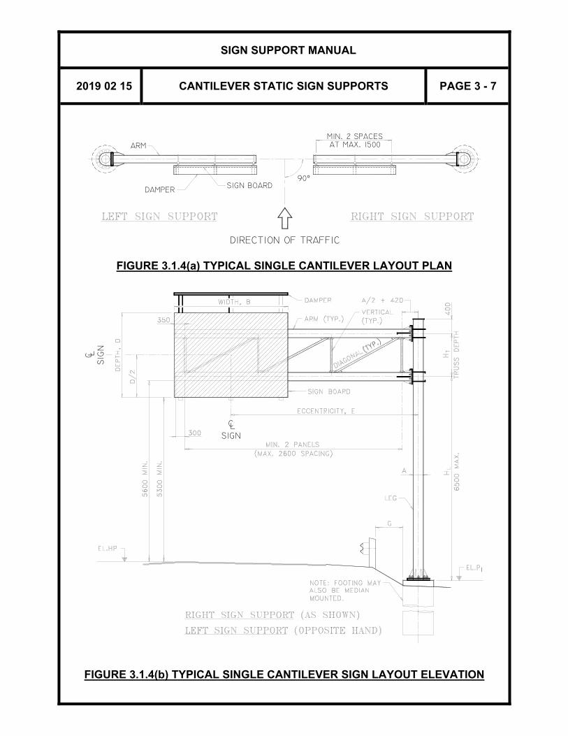
ARM
DIRECTION OF TRAFFIC
90°
MIN. 2 SPACES
SIGN BOARD
AT MAX. 1500
DAMPER
FIGURE 3.1.4(a) TYPICAL SINGLE CANTILEVER LAYOUT PLAN
SIG
NL
C
1
CL SIGN
FIGURE 3.1.4(b) TYPICAL SINGLE CANTILEVER SIGN LAYOUT ELEVATION

SIGN SUPPORT MANUAL
2019 02 15 CANTILEVER STATIC SIGN SUPPORTS PAGE 3 - 8
MIN. 2 SPACESAT MAX. 1500
DIRECTION OF TRAFFIC
DAMPERSIGN BOARD
ARM
90°
DIRECTION OF TRAFFIC
90°
FIGURE 3.1.4(c) TYPICAL BUTTERFLY LAYOUT PLAN
C L
SIG
N
SIGNL C
1
FIGURE 3.1.4(d) TYPICAL BUTTERFLY CANTILEVER SIGN SUPPORT ELEVATION

SIGN SUPPORT MANUAL
2019 02 15 CANTILEVER STATIC SIGN SUPPORTS PAGE 3 - 9
3.2 PROCEDURES 3.2.1 GENERAL
There are four designs (called Classes) for single cantilever and butterfly sign supports. Each Class has a specified set of member dimensions, resulting in different load carrying capacities, (i.e. a Class 4 support can hold a much larger sign than a Class 1 support). The Class is dependent on the sign area, A, the eccentricity, E, and the 50-year Reference Wind Pressure, q, for the proposed location.
3.2.2 DATA REQUIRED
For each sign support, the following data is required: (1) For Single Cantilever Sign Supports:
The sign board dimensions (D x B) and eccentricity, E. Maximum sign area vs. eccentricity curves are shown in Figures 3.2.2(a) to (d) for four different ranges of reference wind pressure. Only the combinations shown below the upper limit line are permissible
(2) For Butterfly Sign Supports:
The sign board area (Aleft and Aright) and eccentricities (Eleft and Eright) from both sides.
Maximum total sign area (Aleft + Aright) vs. eccentricity (maximum of Eleft and Eright) curves are shown in Figures 3.2.2(e) to (h) for four different ranges of reference wind pressure. Only the combinations shown below the upper limit are permissible.
(3) The 50-year reference wind pressure, q.
This value can be obtained for Ontario from Table A2.9(a) to (c) in the Appendix in Section 2 of the Manual.
(4) The site location and orientation of the support. For a proposed highway or a highway under reconstruction, the location should be specified as a station. The orientation or layout shall be as shown in Figures 3.1.4(a) and 3.1.4(c).
(5) The elevation of the highest point on the highway under the sign board, and the final ground elevations under the sign structure footing, at the sign station.

SIGN SUPPORT MANUAL
2019 02 15 CANTILEVER STATIC SIGN SUPPORTS PAGE 3 - 10
FIGURE 3.2.2(a) CLASS RANGES FOR q ≤ 325 Pa (Single Cantilever Sign Support)
FIGURE 3.2.2(b) CLASS RANGES FOR 325 Pa < q ≤ 425 Pa (Single Cantilever Sign Support)
SIGN SUPPORT MANUAL
2019 02 15 CANTILEVER STATIC SIGN SUPPORTS PAGE 3 - 11
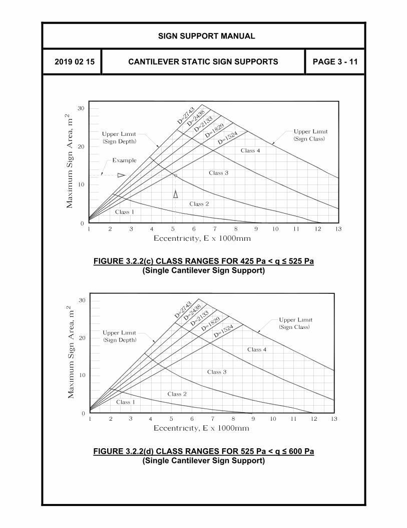
FIGURE 3.2.2(c) CLASS RANGES FOR 425 Pa < q ≤ 525 Pa (Single Cantilever Sign Support)
FIGURE 3.2.2(d) CLASS RANGES FOR 525 Pa < q ≤ 600 Pa (Single Cantilever Sign Support)
SIGN SUPPORT MANUAL
2019 02 15 CANTILEVER STATIC SIGN SUPPORTS PAGE 3 - 12
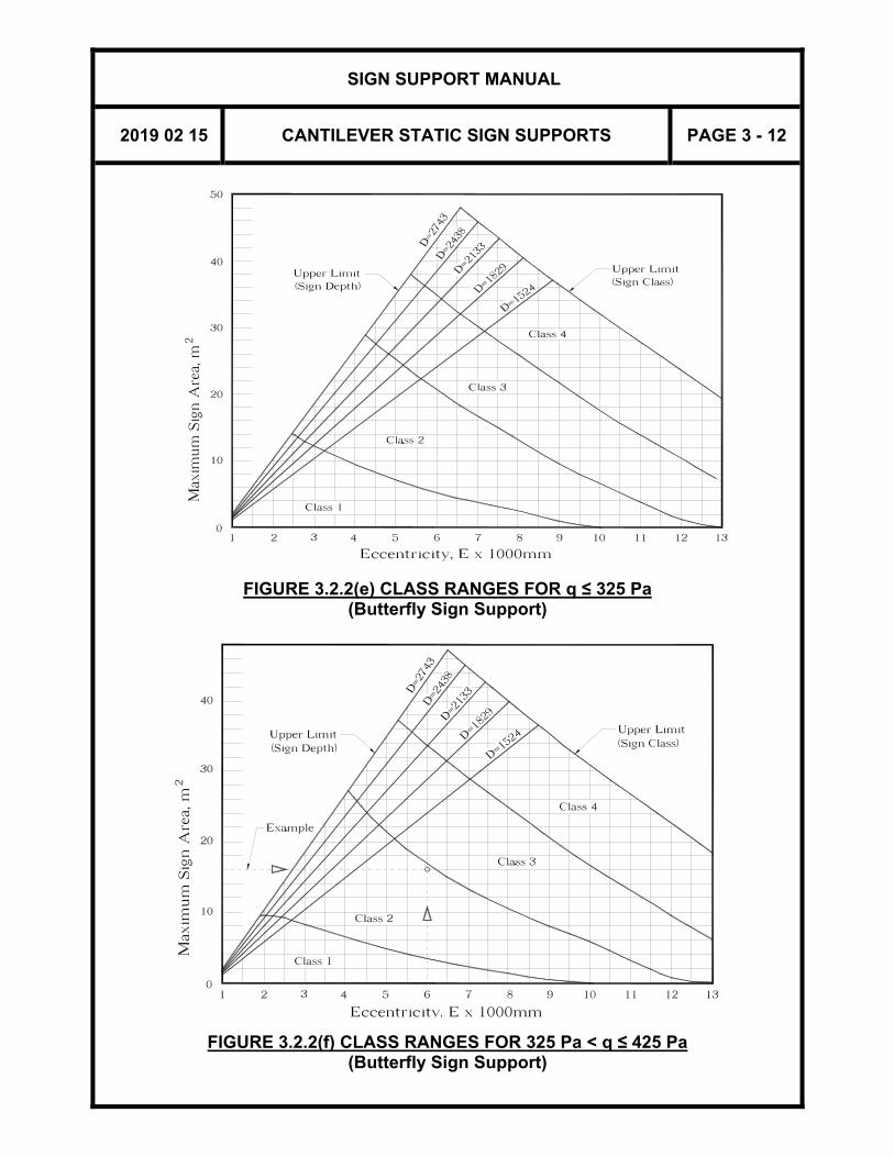
FIGURE 3.2.2(e) CLASS RANGES FOR q ≤ 325 Pa (Butterfly Sign Support)
FIGURE 3.2.2(f) CLASS RANGES FOR 325 Pa < q ≤ 425 Pa (Butterfly Sign Support)

SIGN SUPPORT MANUAL
2019 02 15 CANTILEVER STATIC SIGN SUPPORTS PAGE 3 - 13
FIGURE 3.2.2(g) CLASS RANGES FOR 425 Pa < q ≤ 525 Pa (Butterfly Sign Support)
FIGURE 3.2.2(h) CLASS RANGES FOR 525 Pa < q ≤ 600 Pa (Butterfly Sign Support)

SIGN SUPPORT MANUAL
2019 02 15 CANTILEVER STATIC SIGN SUPPORTS PAGE 3 - 14
3.2.3 PROCEDURE FOR SELECTION OF SINGLE CANTILEVER SIGN SUPPORT
GIVEN: SIGN SIZE AND ECCENTRICITY
Example: 2500 mm x 5000 mm sign board with eccentricity, E, of 5100 mm, and 50-year reference wind pressure, q, of 520 Pa.
STEP 1: OBTAIN THE DESIGN CLASS FOR THE PROPOSED SIGN
E.g. The intersection of the values for sign area of 2.5 x 5 = 12.5 m2 and E = 5100 mm fall within the Class 2 area of the chart on Figure 3.2.2(c) for 425 Pa < q ≤ 525 Pa, and below the upper limit for sign depth of 2500 mm. Therefore, the proposed sign requires a Class 2 sign support.
STEP 2: OBTAIN THE DESIGN DIMENSIONS FOR THE CLASS
E.g. From Tables 3.2.3(a) and 3.2.3(b), and a Class 2 sign support obtain the following: Support Leg: HSS 406 x 12.7 Arms: HSS 273 x 8.0 Verticals/Diagonals: HSS 73 x 4.8 (welded joint option) or
2 No. L 89 x 89 x 9.5 (bolted joint option) Arm Connection Plate: Length = 580 mm Arm Length (E+B/2-50): = 5100+5000/2–50 = 7550 mm Dimension ‘K’ for Camber: = 65 mm CALCULATE PANEL LENGTHS (see Section 3.1.7): The total length of all panels = E+B/2-A/2-350-420 = 5100+5000/2-406/2-770 = 6627 mm Total number panels required = 6627/2600 = 2.55, say 3 panels Average panel length = 6627/3 = 2209 mm P1 = 2209 mm, PTYP = 2209 mm LOCATE Z-BRACKETS (see Section 3.1.8): Let Lx = distance of Z-bracket from end of sign board closest to traffic side.

SIGN SUPPORT MANUAL
2019 02 15 CANTILEVER STATIC SIGN SUPPORTS PAGE 3 - 15
(1) Locate first bracket 200 mm from the end of sign board
nearest traffic side Lx = 200 mm
(2) Locate last bracket 200 mm from the end of sign board nearest leg Lx = 4800 mm
(3) Check for interference with panel point at last location Lx = 350+2209+2209 = 4768 mm Conflict with (2)
(4) Adjust the last Z-bracket’s location to any distance (x) between 125 mm to 500 mm from end of sign board. Still Interference (see Figure 3.2.3(a))
(5) Change end panel length and adjust last Z-bracket location. OK - Satisfies all criteria in Section 3.1.8 and minimizes number of Z-brackets (see Figure 3.2.3(b))
FIGURE 3.2.3(a)

SIGN SUPPORT MANUAL
2019 02 15 CANTILEVER STATIC SIGN SUPPORTS PAGE 3 - 16
FIGURE 3.2.3(b)
STEP 3: CHECK BOUNDARY CONDITIONS
(a) The maximum length of the vertical support leg from the top of the footing to the centreline of the bottom arm shall be 6500 mm.
(b) The dimension measured from the highest point on the
highway, EL.HP, to the bottom of the sign board shall be at least 5300 mm, and to the bottom of the lower arm at least 5600 mm.
(c) Check to see if the sign board interferes with the arm to leg
connection. To avoid interference, the eccentricity shall be equal to or greater than: B/2 + A/2 + 500, where ‘B’ is the width of the sign board, and ‘A’ is the outside diameter of the leg.
E.g., E = 5100 mm > 5000/2+406/2+500 = 3203 mm, OK. If any of the above conditions are not satisfied, the initial design parameters must be revised.

SIGN SUPPORT MANUAL
2019 02 15 CANTILEVER STATIC SIGN SUPPORTS PAGE 3 - 17
STEP 4: COMPLETE THE STANDARD DRAWINGS
On Standard Drawings SS118-24 or SS118-73, and SS118-25,
Enter in Table 1 P1 = 2001 mm
PTYP = 2313 mm And in Table 2
Y1 = 1467 mm Y2 = 1467 mm Y3 = 1466 mm X = 400 mm
Refer to 3.3 for Preparation of Drawings.
3.2.4 PROCEDURE FOR SELECTION OF BUTTERFLY SIGN SUPPORT
GIVEN: SIGN SIZE AND ECCENTRICITY Example: a 2000 mm x 5000 mm sign board with eccentricity, E, of 6000 mm on the left, a 1500 mm x 4000 mm sign board with eccentricity, E, of 4000 mm on the right, and 50-year reference wind pressure, q, of 410 Pa.
STEP 1: OBTAIN THE DESIGN CLASS FOR THE PROPOSED SIGN
E.g. On the left, the sign area (AL) is 2 x 5=10.0 m2. On the right, the sign area (AR) is 1.5 x 4=6.0 m2. The ratio of areas of larger sign to smaller sign is 1.67. It is less than the design limit of 2 of the design charts. The total area of both signs is 16.0 m2. The larger eccentricity is E=6000 mm. The intersection of these values fall within the Class 2 area of the chart of Figure 3.2.2(f) for 325 Pa < q ≤ 425 Pa and below the upper limit for larger sign depths of 2000 mm. Therefore, the proposed sign requires a Class 2 sign support.
STEP 2: OBTAIN THE DESIGN DIMENSIONS FOR THE CLASS E.g. From Tables 3.2.3(a) and 3.2.3(b), and a Class 2 sign support obtain the following: Support Leg: HSS 406 x 12.7 Arms: HSS 273 x 8.0 Verticals/Diagonals: HSS 73 x 4.8 (welded joint option) or 2 No. L 89 x 89 x 9.5 (bolted joint option)
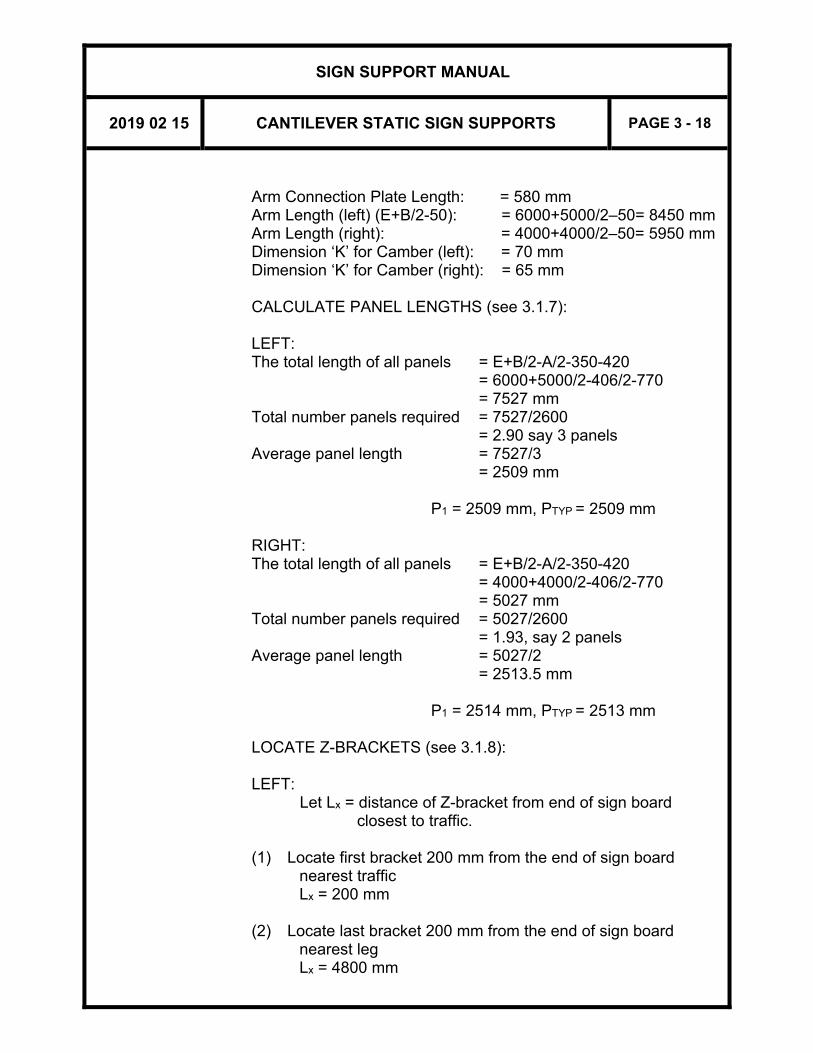
SIGN SUPPORT MANUAL
2019 02 15 CANTILEVER STATIC SIGN SUPPORTS PAGE 3 - 18
Arm Connection Plate Length: = 580 mm Arm Length (left) (E+B/2-50): = 6000+5000/2–50= 8450 mm Arm Length (right): = 4000+4000/2–50= 5950 mm Dimension ‘K’ for Camber (left): = 70 mm Dimension ‘K’ for Camber (right): = 65 mm CALCULATE PANEL LENGTHS (see 3.1.7): LEFT: The total length of all panels = E+B/2-A/2-350-420 = 6000+5000/2-406/2-770 = 7527 mm Total number panels required = 7527/2600 = 2.90 say 3 panels Average panel length = 7527/3 = 2509 mm P1 = 2509 mm, PTYP = 2509 mm RIGHT: The total length of all panels = E+B/2-A/2-350-420 = 4000+4000/2-406/2-770 = 5027 mm Total number panels required = 5027/2600 = 1.93, say 2 panels Average panel length = 5027/2 = 2513.5 mm P1 = 2514 mm, PTYP = 2513 mm LOCATE Z-BRACKETS (see 3.1.8): LEFT:
Let Lx = distance of Z-bracket from end of sign board closest to traffic.
(1) Locate first bracket 200 mm from the end of sign board
nearest traffic Lx = 200 mm
(2) Locate last bracket 200 mm from the end of sign board
nearest leg Lx = 4800 mm
SIGN SUPPORT MANUAL
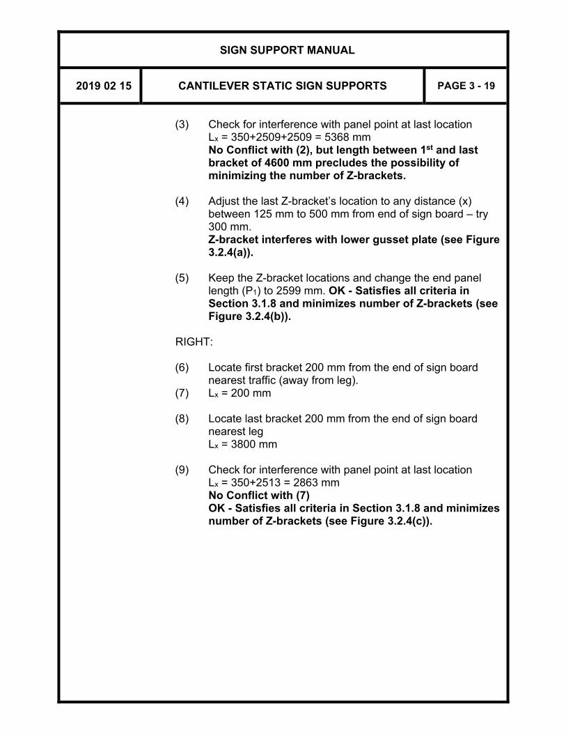
2019 02 15 CANTILEVER STATIC SIGN SUPPORTS PAGE 3 - 19
(3) Check for interference with panel point at last location Lx = 350+2509+2509 = 5368 mm No Conflict with (2), but length between 1st and last
bracket of 4600 mm precludes the possibility of minimizing the number of Z-brackets.
(4) Adjust the last Z-bracket’s location to any distance (x)
between 125 mm to 500 mm from end of sign board – try 300 mm.
Z-bracket interferes with lower gusset plate (see Figure 3.2.4(a)).
(5) Keep the Z-bracket locations and change the end panel
length (P1) to 2599 mm. OK - Satisfies all criteria in Section 3.1.8 and minimizes number of Z-brackets (see Figure 3.2.4(b)).
RIGHT: (6) Locate first bracket 200 mm from the end of sign board
nearest traffic (away from leg). (7) Lx = 200 mm (8) Locate last bracket 200 mm from the end of sign board
nearest leg Lx = 3800 mm
(9) Check for interference with panel point at last location
Lx = 350+2513 = 2863 mm No Conflict with (7) OK - Satisfies all criteria in Section 3.1.8 and minimizes number of Z-brackets (see Figure 3.2.4(c)).

SIGN SUPPORT MANUAL
2019 02 15 CANTILEVER STATIC SIGN SUPPORTS PAGE 3 - 20
FIGURE 3.2.4(a): Left Arm
FIGURE 3.2.4(b): Left Arm

SIGN SUPPORT MANUAL
2019 02 15 CANTILEVER STATIC SIGN SUPPORTS PAGE 3 - 21
FIGURE 3.2.4(c): Right Arm

SIGN SUPPORT MANUAL
2019 02 15 CANTILEVER STATIC SIGN SUPPORTS PAGE 3 - 22
STEP 3: CHECK BOUNDARY CONDITIONS (a) The maximum length of the vertical support leg from the top
of the footing to the centreline of the bottom arm shall be 6500 mm.
(b) For both arms, the dimension measured from the highest
point on the highway, EL.HP, to the bottom of the sign board shall be at least 5300 mm, and to the bottom of the lower arm at least 5600 mm.
(c) Check to see if the sign board interferes with the arm to leg
connection. To avoid interference, the eccentricity shall be equal to or greater than: B/2 + A/2 + 500, where ‘B’ is the width of the sign board, and ‘A’ is the outside diameter of the leg.
E.g., Left: E= 6000 mm > 5000/2+406/2+500= 3203 mm,
OK. Right: E= 4000 mm > 4000/2+406/2+500= 2703 mm, OK.
If any of the above conditions are not satisfied, the initial design parameters must be revised.
STEP 4: COMPLETE THE STANDARD DRAWINGS
On Standard Drawings SS118-22 or SS118-71, and SS118-25, Enter in Table 1
LEFT P1 = 2599 mm PTYP = 2464 mm RIGHT P1 = 2514 mm PTYP = 2513 mm
And in Table 2 LEFT Y1 = 1500 mm Y2 = 1500 mm Y3 = 1500 mm x = 300 mm RIGHT Y1 = 1100 mm Y2 = 1100 mm Y3 = 1400 mm x = 200 mm
SIGN SUPPORT MANUAL
2019 02 15 CANTILEVER STATIC SIGN SUPPORTS PAGE 3 - 23
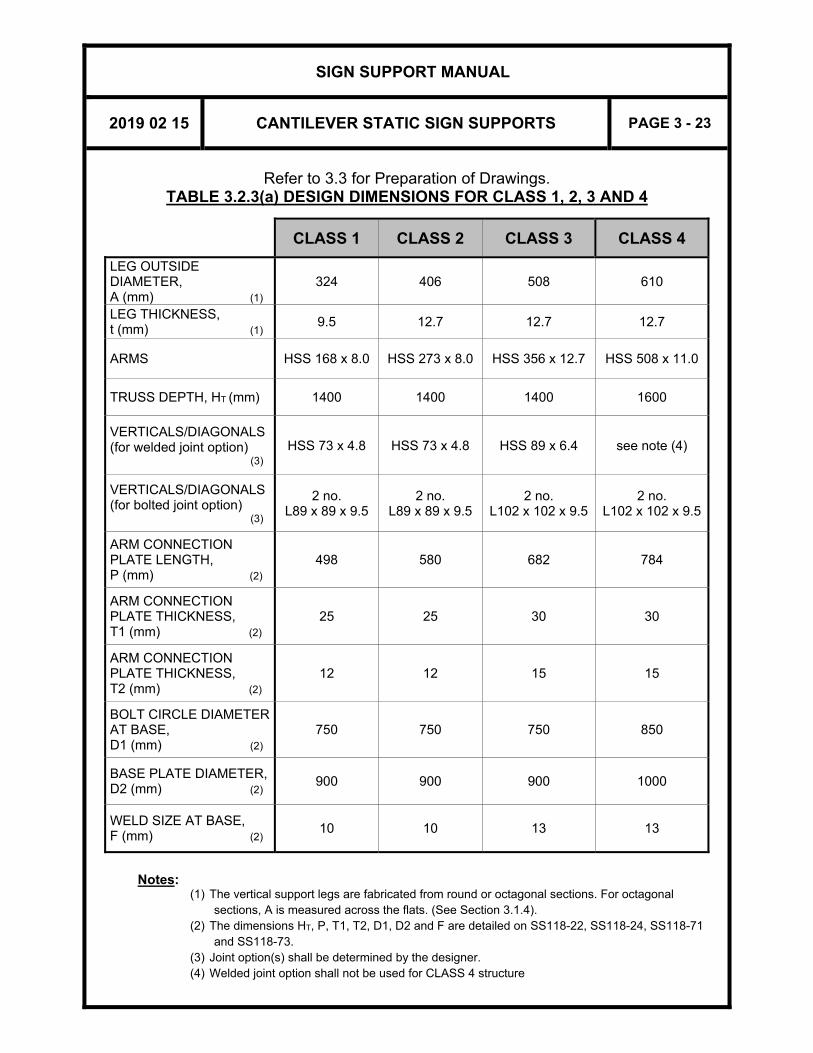
Refer to 3.3 for Preparation of Drawings. TABLE 3.2.3(a) DESIGN DIMENSIONS FOR CLASS 1, 2, 3 AND 4
CLASS 1 CLASS 2 CLASS 3 CLASS 4
LEG OUTSIDE DIAMETER, A (mm) (1)
324 406 508 610
LEG THICKNESS, t (mm) (1)
9.5 12.7 12.7 12.7
ARMS HSS 168 x 8.0 HSS 273 x 8.0 HSS 356 x 12.7 HSS 508 x 11.0
TRUSS DEPTH, HT (mm) 1400 1400 1400 1600
VERTICALS/DIAGONALS (for welded joint option) (3)
HSS 73 x 4.8 HSS 73 x 4.8 HSS 89 x 6.4 see note (4)
VERTICALS/DIAGONALS (for bolted joint option) (3)
2 no. L89 x 89 x 9.5
2 no. L89 x 89 x 9.5
2 no. L102 x 102 x 9.5
2 no. L102 x 102 x 9.5
ARM CONNECTION PLATE LENGTH, P (mm) (2)
498 580 682 784
ARM CONNECTION PLATE THICKNESS, T1 (mm) (2)
25 25 30 30
ARM CONNECTION PLATE THICKNESS, T2 (mm) (2)
12 12 15 15
BOLT CIRCLE DIAMETER AT BASE, D1 (mm) (2)
750 750 750 850
BASE PLATE DIAMETER, D2 (mm) (2)
900 900 900 1000
WELD SIZE AT BASE, F (mm) (2)
10 10 13 13
Notes:
(1) The vertical support legs are fabricated from round or octagonal sections. For octagonal sections, A is measured across the flats. (See Section 3.1.4).
(2) The dimensions HT, P, T1, T2, D1, D2 and F are detailed on SS118-22, SS118-24, SS118-71 and SS118-73.
(3) Joint option(s) shall be determined by the designer. (4) Welded joint option shall not be used for CLASS 4 structure
SIGN SUPPORT MANUAL
2019 02 15 CANTILEVER STATIC SIGN SUPPORTS PAGE 3 - 24
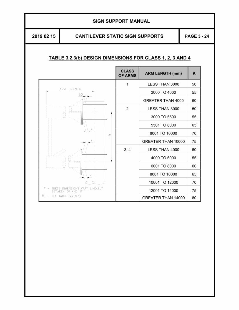
TABLE 3.2.3(b) DESIGN DIMENSIONS FOR CLASS 1, 2, 3 AND 4
CLASS
OF ARMS
ARM LENGTH (mm)
K
1 LESS THAN 3000 50
3000 TO 4000 55
GREATER THAN 4000 60
2 LESS THAN 3000 50
3000 TO 5500 55
5501 TO 8000 65
8001 TO 10000 70
GREATER THAN 10000 75
3, 4 LESS THAN 4000 50
4000 TO 6000 55
6001 TO 8000 60
8001 TO 10000 65
10001 TO 12000 70
12001 TO 14000 75
GREATER THAN 14000 80

SIGN SUPPORT MANUAL
2019 02 15 CANTILEVER STATIC SIGN SUPPORTS PAGE 3 - 25
3.3 PREPARATION OF DRAWINGS 3.3.1 DATA REQUIRED
The sign support structure designer shall obtain information from the Regional Offices for the location, site number, span length, location, elevations and sizes of sign boards etc. of each sign support to be constructed. The designer shall prepare and complete the design standard drawings for the structures and its foundations that will be part of the contract documents. Design drawings shall show the following information: (1) A key plan, indicating the location of each support. (2) The Site number (formerly Structure I.D. number). (3) The eccentricity, measured from centreline of the sign board to the
centreline of support leg. This is required for both signs on butterfly sign supports.
(4) The control line or the centreline of the roadway, and the offset of the
leg from the control line. (5) The elevation of the highest point on the roadway surface under the
support structure. Consider both sides of leg for butterfly sign supports. (6) The height of the supporting leg that is the dimension measured from
the top of footing to the centreline of the bottom arm. This height shall not exceed 6500 mm.
(7) The top of footing elevation. This elevation shall be determined so that
the footing projection above finished grade around it is minimum 300 mm and maximum 1000 mm. This will give the designer flexibility to meet the structure leg height as stated in (6) above.
(8) The elevation of the ground line at the support footing. (9) The offset of the centreline of footing from the control line, either as a
note or as a dimension. (10) The station of the support structure on a designated highway centreline
or control line. (11) A designation for the sign support as a "Left Sign Support" or "Right
Sign Support". Left and Right for this purpose, are defined as if looking

SIGN SUPPORT MANUAL
2019 02 15 CANTILEVER STATIC SIGN SUPPORTS PAGE 3 - 26
in the direction of the traffic, as shown in Figure 3.1.4(a) and (b). For butterfly sign supports, a “Normal Sign Support” would have both sign boards facing the same direction for use in gore areas or medians separating core/collectors, while an “Alternating Sign Support“ would have the two signs facing opposite directions for use on medians (see Figures 3.1.4(c) and (d)).
(12) The footing type (see Section 3.1.5). For ground mounted footings, the
dimension ‘G’ from the rear face of the traffic protection barrier to the sign support footing (see Section 3.1.6).
(13) For the sign board, the following additional information is required:
- An outline in dashed line showing the sign board(s) to be mounted on the support structure,
- The dimensions B and D of the sign board(s).
3.3.2 SIGN SUPPORT DRAWINGS
If the supports are to be supplied and erected as part of a contract, appropriate Standard Drawings from SS118-22, SS118-23, SS118-24, SS118-25, SS118-71, SS118-72, SS118-73, SS118-3 and/or SS118-4 and/or SS118-5 must be used. Up to 5 sign supports can be detailed on one sheet. The Appendix contains reduced prints of these drawings. The Contract and W.P. numbers should be added to the title block. The sheet number is added when the drawings for the entire contract are assembled. On Standard Drawings SS118-22/23/24/25/71/72/73 there are two tables to be completed on the drawings. In each table, one vertical column of data is used for each sign. The Standard Drawings shall be sealed, dated and signed according to Section 2.4.1. The data required to complete Table 1 - General consists of the following:
(i) Local Reference Wind Pressure, (Pa). (ii) Frost Depth. Frost depths are given in the Appendix of Section 2 of this
Manual and may be used if the recommendations of a geotechnical engineer are not available.
(iii) Station. (iv) Site number.

SIGN SUPPORT MANUAL
2019 02 15 CANTILEVER STATIC SIGN SUPPORTS PAGE 3 - 27
v) Sign Orientation. Specify L for Left Sign or R for Right Sign. For butterfly sign supports, specify N for normal or A for alternating signs (see Figure 3.1.4(a) and Figure 3.1.4(c)).
(vi) Sign Size(s) (D x B). (vii) Sign Class (see Section 3.2). (viii) Eccentricity from the centreline of the vertical support leg to the centre
of the sign board(s), E. (ix) Barrier-to-Support clearance(s), G (see Section 3.1.6). (x) Elevation of the highest point on the highway under the sign, including
shoulders, curbs, and medians, EL.HP. (xi) Elevation at top of the support footing, EL.P1. (xii) Member Dimensions: A, t; arm size, P and K (left and right); tabulated
on Table 3.2.3 for all support Classes. (xiii) Number of Panels (Zero indicates that arm is so short that
verticals/diagonals are not required – see Section 3.1.7(1)). (xiv) Length of Panels. (xv) Footing Type (see Section 3.1.5). (xvi) Design Information HT, P, D1, D2, F, T1 and T2 (see Table 3.2.3(a)). Table 2 – Z-Bracket Locations is to be completed with the dimensions required to locate the Z-brackets for mounting the sign board to the support. The length of the Z-bracket shall also be included. The following information may be used for the calculation of quantities:
DESCRIPTION QUANTITY
12.7mm DIA. STAINLESS STEEL U-BOLT 2 per Z-Bracket
STAINLESS STEEL NYLON INSERT STOP NUT 4 per Z-Bracket
STAINLESS STEEL WASHER 8 per Z-Bracket
PROFILED CHANNEL (C130x13) 2 per Z-Bracket
Z-BRACKET See 3.1.7
ALUMINUM ALCAN SHAPE No.72838 See 2.10
8mm DIA. STAINLESS STEEL CAP BOLT C/W NUT AND WASHER (SIGN BOARD)
(No. of Aluminum Alcan Shapes + 1) per Z-Bracket
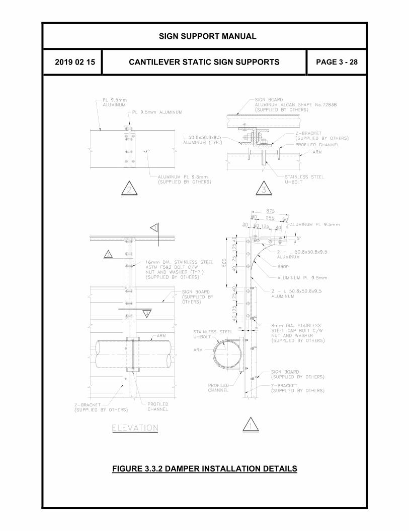
DAMPER VERTICAL ANGLE 2 per Z-Bracket
DAMPER GUSSET 1 per Z-Bracket
DAMPER HORIZONTAL ANGLE 2 per Z-Bracket
DAMPER PLATE 1 per Sign board (See Note below)
16mm DIA. STAINLESS STEEL ASTM F593 BOLT C/W NUT AND WASHER (DAMPER)
12 per Z-Bracket
Note: The damper plate may be comprised of two or more plate elements. The length of
each component plate shall be at least twice the distance between Z-brackets.
SIGN SUPPORT MANUAL
2019 02 15 CANTILEVER STATIC SIGN SUPPORTS PAGE 3 - 28
FIGURE 3.3.2 DAMPER INSTALLATION DETAILS

SIGN SUPPORT MANUAL
2019 02 15 CANTILEVER STATIC SIGN SUPPORTS PAGE 3 - 29
3.4 MAINTENANCE AND INSPECTION
All components must be properly inspected and maintained according to the requirements described in the Sign Support Inspection Guidelines, 2002. Long term durability of sign supports is dependent on routine maintenance and inspection. In order to prevent corrosion damage and fatigue problems to the anchorage assembly, and to allow for proper inspection of the assembly, the following shall be ensured: (i) The base of the vertical support leg shall be kept free from dirt and
debris (ii) The surrounding ground level shall be a minimum of 300 mm below the
top of the footing The base plate and arm connection welds shall be inspected regularly for fatigue cracking. Check tightening of connection and anchor bolts periodically. Clear vent holes of truss members if there is debris or salt build-up.
3.5 DESIGN INFORMATION 3.5.1 GENERAL
Design and detailing data contained in this Section conforms to the requirements of the Canadian Highway Bridge Design Code CAN/CSA-S6-06 unless otherwise stated.
Calculations are based on Standard CAN/CSA-G40.20-13/G40.21-13 Grade 300W or ASTM A500 Grade C or API-5L-X46 (for round section of outside diameter equal to or greater than 508mm) for structural steel, and 30 MPa concrete and Grade 400W reinforcing steel for footings.
The total weight of the sign board used in design is 0.169 kN/m2 (3.52 psf), including the self-weight of the standard aluminum ALCAN shape No.72838. The total weight of the damper varies between 0.15 and 0.20 kN/m of sign board, depending on the width of sign. Dead load deflection is compensated by cambering the arms and sign board by means of adjusting the dimension ‘K’ at the arm to leg connections (see Table 3.2.3(b)). As specified in CHBDC, the arms and leg are designed for the full wind load applied to all truss members, sign boards and attachments. For the design of

SIGN SUPPORT MANUAL
2019 02 15 CANTILEVER STATIC SIGN SUPPORTS PAGE 3 - 30
the leg, this is applied in conjunction with a torsion load obtained by neglecting the wind loading on components that reduce the primary torsion effect. Load combinations considering snow loading on the damping plates and ice accretion have also been included. The vertical and diagonal member sizes have been upsized for aesthetic reasons. Bolted connection of these members have been designed for the larger of the actual joint force or 75% of the original member (before upsizing) capacity. Fatigue wind loads were obtained from the AASHTO Standard Specifications for Structural Supports for Highway Signs, Luminaries and Traffic Signals 4th Edition, 2001. In 1998, MTO retained Rowan Williams Davies & Irwin Inc. (RWDI) to conduct an aeroelastic model study of a Single Cantilever Sign Support. The objectives of the study were: i) to calculate the natural frequencies for various configurations of the
supports, ii) to identify any aerodynamic instabilities, such as vortex-induced
oscillations and galloping, and iii) to provide wind loads and fatigue analysis required to verify the sign
support design.
During testing, it became apparent that galloping oscillations of unacceptable amplitude were likely to occur on the signs under certain wind conditions. Investigation of a solution to the galloping problem was then carried out. As a result of this work, a damping device was added to control galloping. All information relating to this wind tunnel test, including conclusions and recommendations, are contained in the publication “Final Report - Aeroelastic Model Study for Cantilever Sign Supports, Ontario, Canada.”
3.5.2 DERIVATION OF DESIGN CURVES
The design curves for the cantilever type sign supports found in Figure 3.2.2(a) to (h) were derived by determining the member responses under various sign areas, eccentricities, and wind loads. Member responses were checked for ultimate, serviceability, and fatigue limits states.
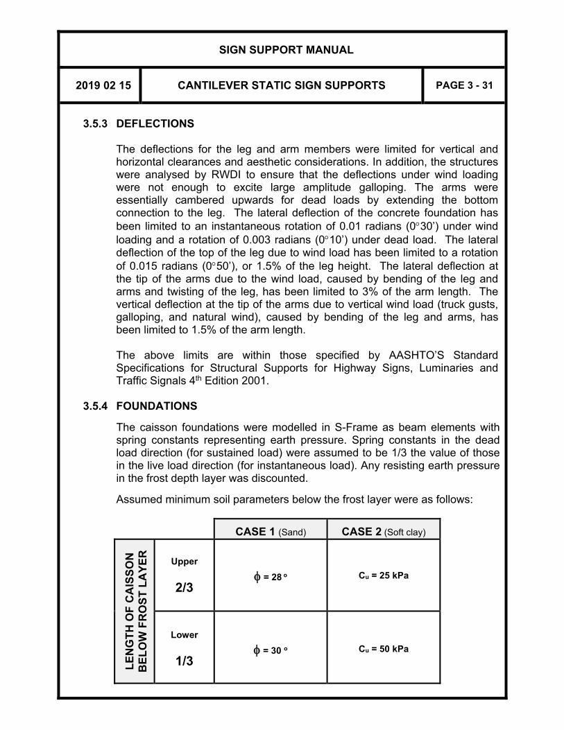
SIGN SUPPORT MANUAL
2019 02 15 CANTILEVER STATIC SIGN SUPPORTS PAGE 3 - 31
3.5.3 DEFLECTIONS The deflections for the leg and arm members were limited for vertical and horizontal clearances and aesthetic considerations. In addition, the structures were analysed by RWDI to ensure that the deflections under wind loading were not enough to excite large amplitude galloping. The arms were essentially cambered upwards for dead loads by extending the bottom connection to the leg. The lateral deflection of the concrete foundation has been limited to an instantaneous rotation of 0.01 radians (030’) under wind loading and a rotation of 0.003 radians (010’) under dead load. The lateral deflection of the top of the leg due to wind load has been limited to a rotation of 0.015 radians (050’), or 1.5% of the leg height. The lateral deflection at the tip of the arms due to the wind load, caused by bending of the leg and arms and twisting of the leg, has been limited to 3% of the arm length. The vertical deflection at the tip of the arms due to vertical wind load (truck gusts, galloping, and natural wind), caused by bending of the leg and arms, has been limited to 1.5% of the arm length. The above limits are within those specified by AASHTO’S Standard Specifications for Structural Supports for Highway Signs, Luminaries and Traffic Signals 4th Edition 2001.
3.5.4 FOUNDATIONS
The caisson foundations were modelled in S-Frame as beam elements with spring constants representing earth pressure. Spring constants in the dead load direction (for sustained load) were assumed to be 1/3 the value of those in the live load direction (for instantaneous load). Any resisting earth pressure in the frost depth layer was discounted.
Assumed minimum soil parameters below the frost layer were as follows:
CASE 1 (Sand)
CASE 2 (Soft clay)
L
EN
GT
H O
F C
AIS
SO
N
BE
LO
W F
RO
ST
LA
YE
R
Upper
2/3
= 28 o
Cu = 25 kPa
Lower
1/3
= 30 o
Cu = 50 kPa
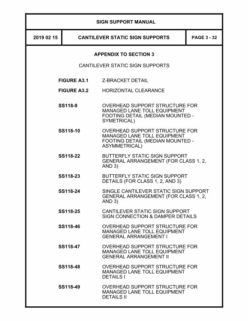
SIGN SUPPORT MANUAL
2019 02 15 CANTILEVER STATIC SIGN SUPPORTS PAGE 3 - 32
APPENDIX TO SECTION 3
CANTILEVER STATIC SIGN SUPPORTS
FIGURE A3.1 Z-BRACKET DETAIL FIGURE A3.2 HORIZONTAL CLEARANCE SS118-9 OVERHEAD SUPPORT STRUCTURE FOR MANAGED LANE TOLL EQUIPMENT
FOOTING DETAIL (MEDIAN MOUNTED - SYMETRICAL)
SS118-10 OVERHEAD SUPPORT STRUCTURE FOR MANAGED LANE TOLL EQUIPMENT
FOOTING DETAIL (MEDIAN MOUNTED - ASYMMETRICAL)
SS118-22 BUTTERFLY STATIC SIGN SUPPORT
GENERAL ARRANGEMENT (FOR CLASS 1, 2, AND 3)
SS118-23 BUTTERFLY STATIC SIGN SUPPORT DETAILS (FOR CLASS 1, 2, AND 3) SS118-24 SINGLE CANTILEVER STATIC SIGN SUPPORT
GENERAL ARRANGEMENT (FOR CLASS 1, 2, AND 3)
SS118-25 CANTILEVER STATIC SIGN SUPPORT SIGN CONNECTION & DAMPER DETAILS SS118-46 OVERHEAD SUPPORT STRUCTURE FOR MANAGED LANE TOLL EQUIPMENT GENERAL ARRANGEMENT I SS118-47 OVERHEAD SUPPORT STRUCTURE FOR MANAGED LANE TOLL EQUIPMENT GENERAL ARRANGEMENT II SS118-48 OVERHEAD SUPPORT STRUCTURE FOR MANAGED LANE TOLL EQUIPMENT DETAILS I SS118-49 OVERHEAD SUPPORT STRUCTURE FOR MANAGED LANE TOLL EQUIPMENT DETAILS II
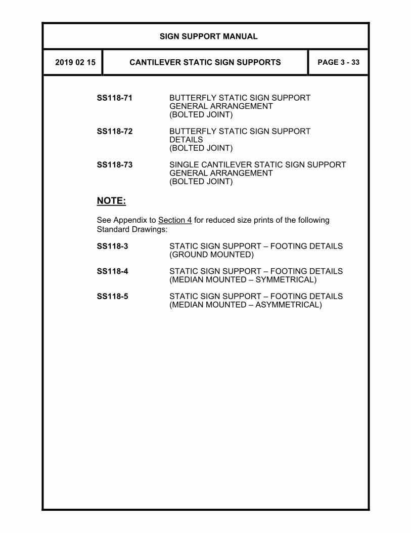
SIGN SUPPORT MANUAL
2019 02 15 CANTILEVER STATIC SIGN SUPPORTS PAGE 3 - 33
SS118-71 BUTTERFLY STATIC SIGN SUPPORT
GENERAL ARRANGEMENT (BOLTED JOINT)
SS118-72 BUTTERFLY STATIC SIGN SUPPORT DETAILS (BOLTED JOINT) SS118-73 SINGLE CANTILEVER STATIC SIGN SUPPORT
GENERAL ARRANGEMENT (BOLTED JOINT)
NOTE: See Appendix to Section 4 for reduced size prints of the following Standard Drawings:
SS118-3 STATIC SIGN SUPPORT – FOOTING DETAILS (GROUND MOUNTED) SS118-4 STATIC SIGN SUPPORT – FOOTING DETAILS (MEDIAN MOUNTED – SYMMETRICAL) SS118-5 STATIC SIGN SUPPORT – FOOTING DETAILS (MEDIAN MOUNTED – ASYMMETRICAL)

SIGN SUPPORT MANUAL
2019 02 15 CANTILEVER STATIC SIGN SUPPORTS PAGE 3 - 34
FIGURE A3.1 Z-BRACKET DETAIL

SIGN SUPPORT MANUAL
2019 02 15 CANTILEVER STATIC SIGN SUPPORTS PAGE 3 - 35
FIGURE A3.2 HORIZONTAL CLEARANCE

This page is intentionally left blank.

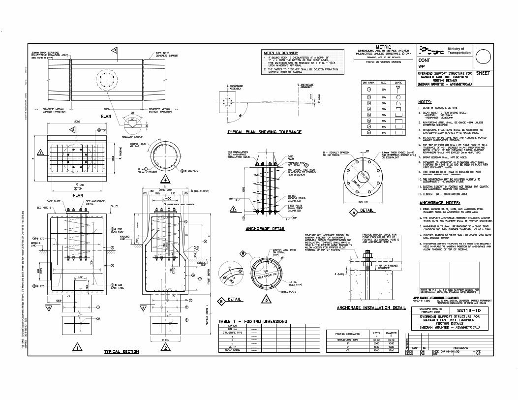

≥


≥

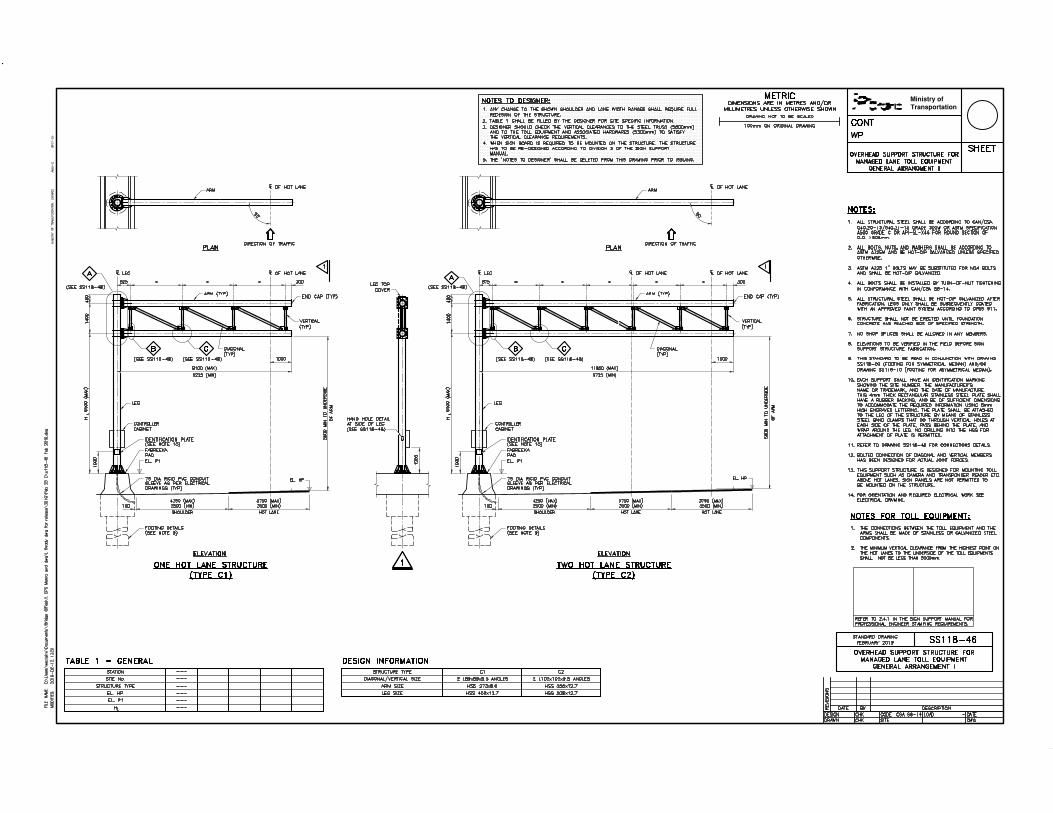


≥


≥

This page is intentionally left blank.

SIGN SUPPORT MANUAL
SECTION 4 – TRI-CHORD STATIC SIGN SUPPORTS
February 2019


SIGN SUPPORT MANUAL
2019 02 15 TRI-CHORD STATIC SIGN SUPPORTS PAGE 4 - 1
4 TRI-CHORD STATIC SIGN SUPPORTS 4.1 GENERAL
Tri-Chord overhead truss sign supports are used to support static sign boards. There are two types of Tri-Chord static sign supports, namely ‘simply supported’ and ‘cantilever.’
4.1.1 STANDARD SIGN SUPPORTS 4.1.1.1 SIMPLY SUPPORTED TYPE I
Simply supported Tri-Chord Type I overhead sign support structures are designed to the requirements of CSA S6-14 (CHBDC). The sign supports in this section are designed for sign boards and site conditions that meet the following criteria: (a) Spans from 14000 to 36000 mm (b) Maximum total sign area of 45 square metres for a reference wind
pressure of 600 Pa at a return period of 50 years, unless modified as described in Section 4.2.3 (Case 2). The effect of wind funnelling due to special topographical features such as deep valleys is not considered (CHBDC 3.10.1.2)
(c) Depth of sign board from 1525 mm (5 ft) up to and including 2745 mm
(9 ft) (d) All sign boards shall be vertically centred on the truss (e) Location of supports and vertical clearance according to the
requirements of the CHBDC and MTO Design Supplement for TAC Geometric Design Guide for Canadian Roads, 2017
(f) Competent soil conditions (as described in Section 4.5.4) excluding
rock fill
4.1.1.2 SIMPLY SUPPORTED TYPE II
Simply supported Tri-Chord Type II overhead sign support structures are designed to the requirements of the CSA S6-14 (CHBDC).
SIGN SUPPORT MANUAL
2019 02 15 TRI-CHORD STATIC SIGN SUPPORTS PAGE 4 - 2
The sign supports in this section are designed for sign boards and site conditions that meet the following criteria: (a) Spans from 21000 to 36000 mm (b) Maximum total sign area of 45 square metres for a reference wind
pressure of 600 Pa at a return period of 50 years, unless modified as described in Section 4.2.3 (Case 2). The effect of wind funnelling due to special topographical features such as deep valleys is not considered (CHBDC 3.10.1.2)
(c) Depth of sign board from 2745 mm (9 ft) up to 3965 mm (13 ft) (d) All sign boards shall be vertically centred on the truss (e) Location of supports and vertical clearance according to the
requirements of the CHBDC and MTO Design Supplement for TAC Geometric Design Guide for Canadian Roads, 2017
(f) Competent soil conditions (as described in Section 4.5.4) excluding
rock fill (g) Sign board is located a minimum of 1000 mm from the centreline of the
leg
4.1.1.3 CANTILEVER TYPE
Cantilever Tri-Chord overhead sign support structures are designed to the requirements of the CAN/CSA S6-06 (CHBDC).
The sign supports in this section are designed for sign boards and site conditions that meet the following criteria: (a) Cantilever span from 12000 to 18000 mm
(b) Maximum total sign area of 26.7 square metres for a reference wind pressure of 600 Pa at a return period of 50 years. The effect of wind funnelling due to special topographical features such as deep valleys is not considered (CHBDC 3.10.1.2)
(c) Depth of sign board from 1525 mm (5 ft) up to 2745 mm (9 ft)
(d) All sign boards shall be vertically centred on the truss

SIGN SUPPORT MANUAL
2019 02 15 TRI-CHORD STATIC SIGN SUPPORTS PAGE 4 - 3
(e) Location of supports and vertical clearance according to the
requirements of the CHBDC and MTO Design Supplement for TAC Geometric Design Guide for Canadian Roads, 2017
(f) Competent soil conditions (as described in Section 4.5.4) excluding rock fill
4.1.2 LIMITATIONS
For economic and practical reasons, the structure’s vertical support members (legs) should be placed as close as possible to the edge of the travelled portion of the highway (see Section 4.1.5). Therefore, the supports will probably be in the clear recovery zone and should be protected as discussed in Section 2.6. Supports can also be located on median barriers. For ground mounted footings, the top of footing elevation shall be a minimum of 300 mm above the finished grade. This could be increased up to 1000 mm in order to limit the leg height. The dimension from the top of the footing to the centreline of the bottom chord shall not exceed the dimension indicated in Figures 4.1.3(b) and 4.1.3(d).
4.1.3 DESCRIPTION OF SIGN SUPPORTS
The Tri-Chord sign support system is fabricated from structural steel and is comprised of one or two vertical support legs and a three-chord truss. The system is fabricated based on specific site requirements. It is designed for ground mounting or mounting on concrete median barriers. The typical layout plan and elevation are shown in Figures 4.1.3 (a) to (d).
The legs are straight and made from single circular HSS sections or fabricated from plate to an octagonal shape. They are connected at the base to concrete footings by a bolted anchorage. The leg lengths of the simply supported Tri-Chord are not standard. At a particular location the legs may be of different heights, provided the truss is installed with its centreline oriented in the horizontal direction and the elevations of the top of support footings differ from one another.
The three chords are interconnected by diagonals with welded gusset plate connections, forming a spatial core. All members are fabricated from circular HSS sections. All sign boards are attached to the front top and bottom chords using aluminium Z-brackets. For the simply supported type, the front chords are supported on the leg by corbels. The middle or back chord is connected to the front chords by end diagonals. For the cantilever type, the three chords are bolted to the leg through a gusset plate connection.
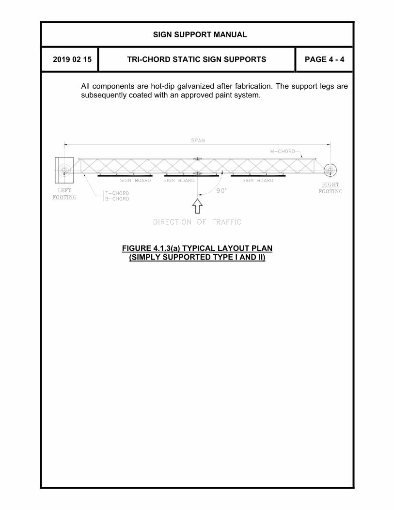
SIGN SUPPORT MANUAL
2019 02 15 TRI-CHORD STATIC SIGN SUPPORTS PAGE 4 - 4
All components are hot-dip galvanized after fabrication. The support legs are subsequently coated with an approved paint system.
FIGURE 4.1.3(a) TYPICAL LAYOUT PLAN
(SIMPLY SUPPORTED TYPE I AND II)
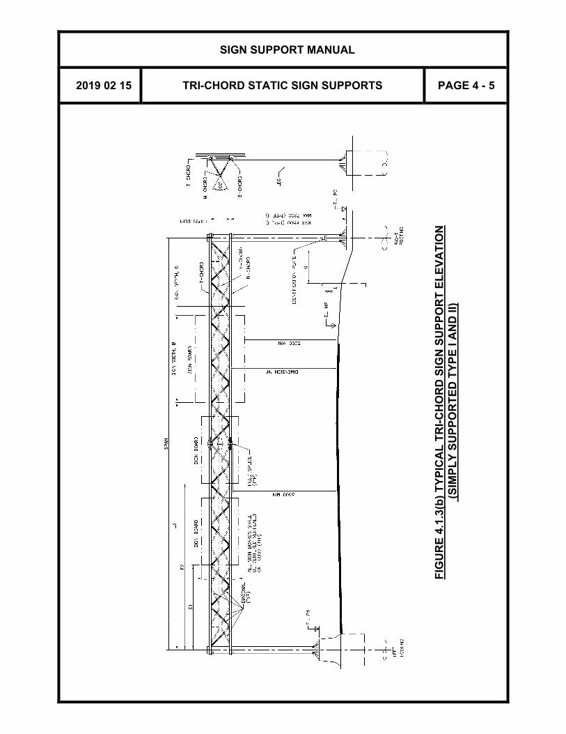
SIGN SUPPORT MANUAL
2019 02 15 TRI-CHORD STATIC SIGN SUPPORTS PAGE 4 - 5
FIG
UR
E 4
.1.3
(b)
TY
PIC
AL
TR
I-C
HO
RD
SIG
N S
UP
PO
RT
EL
EV
AT
ION
(
SIM
PL
Y S
UP
PO
RT
ED
TY
PE
I A
ND
II)

SIGN SUPPORT MANUAL
2019 02 15 TRI-CHORD STATIC SIGN SUPPORTS PAGE 4 - 6
FIGURE 4.1.3 (c) TYPICAL LAYOUT PLAN (CANTILEVER TYPE)
FIGURE 4.1.3 (d) TYPICAL TRI-CHORD SIGN SUPPORT ELEVATION (CANTILEVER TYPE)
x

SIGN SUPPORT MANUAL
2019 02 15 TRI-CHORD STATIC SIGN SUPPORTS PAGE 4 - 7
4.1.4 FOOTINGS
Each sign support footing consists of a reinforced concrete caisson. Details differ according to their location, and generally are of two types, as shown on the standard drawings: ground mounted signs and median mounted signs (see Standard Drawings SS118-3, SS118-4 and SS118-5).
The indicated footing depths are the minimum required for each support. Footing proportions assume competent soil conditions of uniform composition. Parameters upon which the design is based are given in Section 4.5.4.
Encountered soil conditions such as rock fill, land fill, and soft material are not covered here and require the footing to be designed by an Engineer.
4.1.5 CLEARANCE
For ground mounted footings, the minimum horizontal clearance ‘G’ from the back of traffic protection barrier to the nearest face of sign support footing shall not be less than the values specified in Figure A3.2 (see Appendix to Section 3).
Dimension ‘H’ is a characteristic dimension for vertical clearance. The values of dimension ‘H’ ensure that the following requirements are met:
Minimum vertical clearance from the highest point on the highway, including shoulders, curbs, and medians, to the bottom of the deepest sign board shall not be less than 5300 mm under dead load deflection.
Minimum vertical clearance from the highest point on the highway, including shoulders, curbs, and medians, to the bottom of the lowest chord shall not be less than 5600 mm under dead load deflection.
Small sign boards with limited strength connections are allowed to project below the bottom edge of a sign board, as long as damage to them does not cause damage to the structure or present a hazard to traffic below (see Figure A4.2).
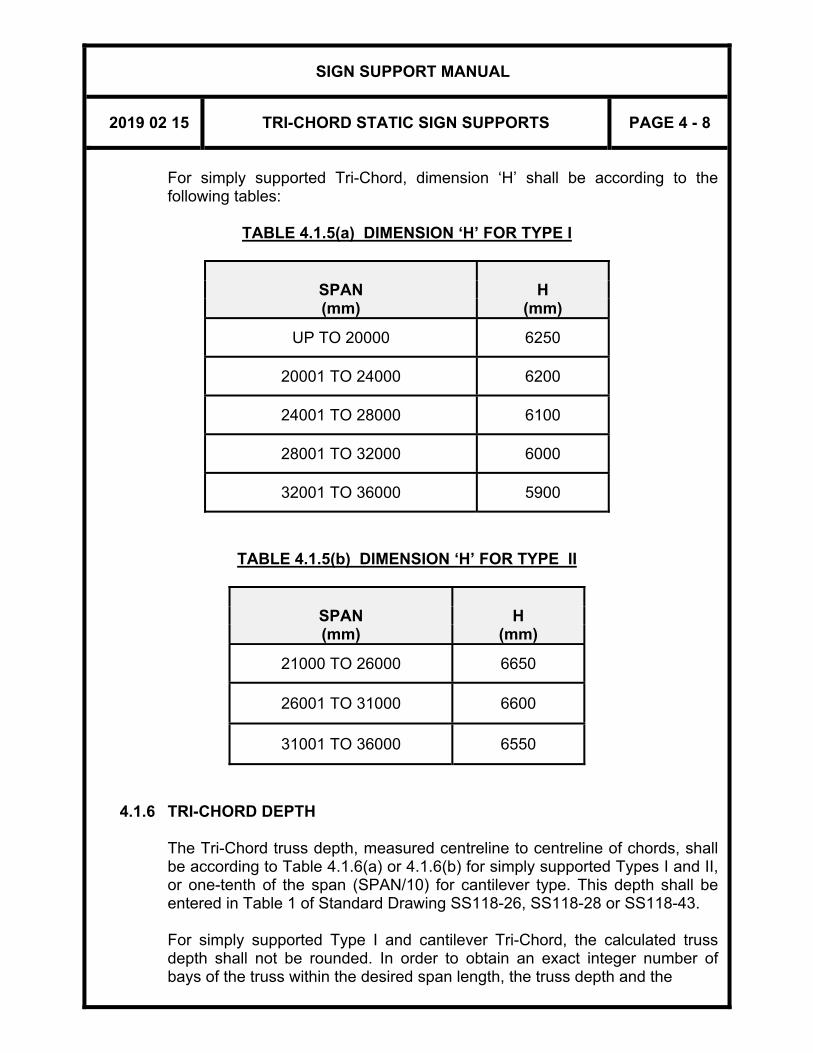
SIGN SUPPORT MANUAL
2019 02 15 TRI-CHORD STATIC SIGN SUPPORTS PAGE 4 - 8
For simply supported Tri-Chord, dimension ‘H’ shall be according to the following tables:
TABLE 4.1.5(a) DIMENSION ‘H’ FOR TYPE I
SPAN H (mm) (mm)
UP TO 20000 6250
20001 TO 24000 6200
24001 TO 28000 6100
28001 TO 32000 6000
32001 TO 36000 5900
TABLE 4.1.5(b) DIMENSION ‘H’ FOR TYPE II
SPAN H (mm) (mm)
21000 TO 26000 6650
26001 TO 31000 6600
31001 TO 36000 6550
4.1.6 TRI-CHORD DEPTH
The Tri-Chord truss depth, measured centreline to centreline of chords, shall be according to Table 4.1.6(a) or 4.1.6(b) for simply supported Types I and II, or one-tenth of the span (SPAN/10) for cantilever type. This depth shall be entered in Table 1 of Standard Drawing SS118-26, SS118-28 or SS118-43.
For simply supported Type I and cantilever Tri-Chord, the calculated truss depth shall not be rounded. In order to obtain an exact integer number of bays of the truss within the desired span length, the truss depth and the
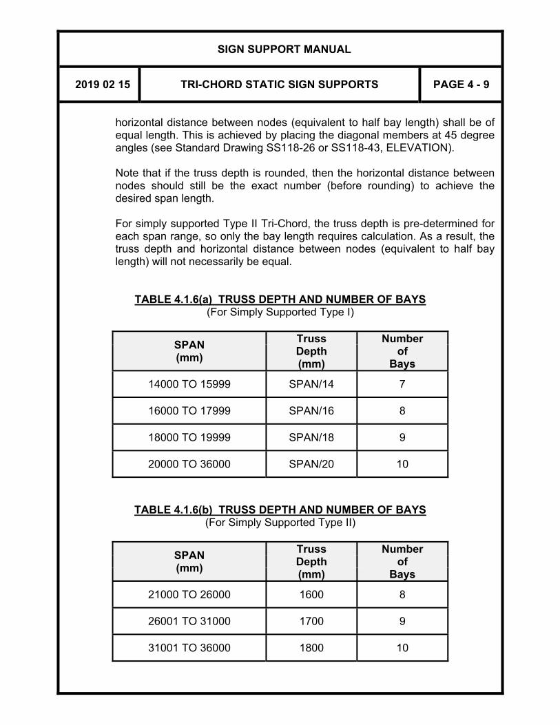
SIGN SUPPORT MANUAL
2019 02 15 TRI-CHORD STATIC SIGN SUPPORTS PAGE 4 - 9
horizontal distance between nodes (equivalent to half bay length) shall be of equal length. This is achieved by placing the diagonal members at 45 degree angles (see Standard Drawing SS118-26 or SS118-43, ELEVATION).
Note that if the truss depth is rounded, then the horizontal distance between nodes should still be the exact number (before rounding) to achieve the desired span length. For simply supported Type II Tri-Chord, the truss depth is pre-determined for each span range, so only the bay length requires calculation. As a result, the truss depth and horizontal distance between nodes (equivalent to half bay length) will not necessarily be equal.
TABLE 4.1.6(a) TRUSS DEPTH AND NUMBER OF BAYS (For Simply Supported Type I)
SPAN (mm)
Truss Number Depth of (mm) Bays
14000 TO 15999 SPAN/14 7
16000 TO 17999 SPAN/16 8
18000 TO 19999 SPAN/18 9
20000 TO 36000 SPAN/20 10
TABLE 4.1.6(b) TRUSS DEPTH AND NUMBER OF BAYS (For Simply Supported Type II)
SPAN (mm)
Truss Number Depth of (mm) Bays
21000 TO 26000 1600 8
26001 TO 31000 1700 9
31001 TO 36000 1800 10
SIGN SUPPORT MANUAL
2019 02 15 TRI-CHORD STATIC SIGN SUPPORTS PAGE 4 - 10
4.1.7 SUPPLY AND ERECTION
Since the support structure may be erected without sign boards, sign boards and Z-brackets (Figure A4.1) are not included in the contract; they are supplied and installed by others. The spacing of Z-brackets for the attachment of the sign boards shall be equal to: a) Half bay length (equivalent to full depth of truss) for simply supported Type I with spans less than or equal to 30000 mm; or cantilever span less than or equal to 15000 mm; b) Quarter bay length (equivalent to half depth of truss) for simply supported Type I with spans greater than 30000 mm; or cantilever span greater than 15000 mm; c) Quarter bay length for all spans of simply supported Type II (as per Standard Drawing SS118-28). Minimum number of Z-brackets per sign shall be three, except for small signs of size not larger than 1.5 m wide x 1.8 m deep, for which two Z-brackets may be used.
Construction shall meet the requirements of OPSS 915, Construction Specification for Sign Support Structures, and associated Special Provisions. Each sign support shall have a corrosion-protected identification plate showing the site number (formerly structure I.D. number), the manufacturer's name or the trade mark, the date of manufacture, the maximum allowable sign board area, and the local reference wind pressure.
4.2 PROCEDURES 4.2.1 GENERAL
The sign supports are fabricated from shop drawings prepared based on the completed contract standard drawings.
The design of the simply supported Tri-Chord overhead sign supports is based on the criteria listed in Section 4.1.1.1 or 4.1.1.2. Based on the required total sign board area (45m2), sign depth, and the span, the final design dimensions can be obtained from Table 4.2.1(a) or 4.2.1(b). For required total sign board area greater than 45 m2,refer Section 4.2.3 (Case 2). The design of the cantilever Tri-Chord is based on the criteria listed in Section 4.1.1.3. There are four designs (called Classes) for cantilever Tri-Chord sign

SIGN SUPPORT MANUAL
2019 02 15 TRI-CHORD STATIC SIGN SUPPORTS PAGE 4 - 11
supports; the Class is dependent on the length of cantilever span and has a specified set of member dimensions, as shown in Table 4.2.1(c).
4.2.2 DATA REQUIRED
For each Tri-Chord sign support structure, the following data is required: (1) The required total sign board area, sign depth, and span (2) The location of the structure (note: for a proposed highway or a
highway under reconstruction, the location should be specified as a station)
(3) The elevation of the highest point on the highway under the sign
boards, and the final ground elevations at the sign support structure location
4.2.3 PROCEDURE FOR SELECTION OF SIGN SUPPORT
CASE 1 – SIMPLY SUPPORTED TRI-CHORD TYPE I WITH SIGN BOARD AREA LESS THAN OR EQUAL TO 45 m2 AND SIGN DEPTH ≤ 2745 mm
GIVEN: REQUIRED SIGN BOARD AREA, SIGN DEPTH AND SPAN
Example: a required sign board area of 30 m2, sign depth of 2440 mm and a span of 20500 mm.
STEP 1: IDENTIFY THE APPLICABLE TRI-CHORD TYPE AND OBTAIN
THE STRUCTURE DESIGN DIMENSIONS FOR THE DESIGN SIGN BOARD AREA
E.g. For sign depth less than 2745 mm, Tri-chord Type I is selected. From Table 4.2.1(a), for a span of 20500 mm, select the span range of 20001 to 22000 mm. For the given example, the following is obtained:
Top and Bottom Chord: HSS 102 x 6.4 Middle or Back Chord: HSS 141 x 6.4 Diagonals: HSS 48 x 3.2 Support Leg: HSS 406 x 12.7 Calculate truss depth from Table 4.1.6. E.g. for span of 20500 mm, truss depth = 20500/20 = 1025 mm.
SIGN SUPPORT MANUAL
2019 02 15 TRI-CHORD STATIC SIGN SUPPORTS PAGE 4 - 12
STEP 2: CHECK BOUNDARY CONDITIONS
(a) Based on the elevation of the highest point of the roadway (EL.HP) and dimension ‘H’ (from Table 4.1.5(a)) corresponding to the span, calculate the elevation of the centreline of the bottom chord of the truss.
(b) Based on the elevation of the centreline of the bottom chord
of the truss and the elevation of the ground at the footing location, calculate the height difference between these two elevations.
(c) This height difference shall be made up of two
components/portions: (1) The leg with a limitation of 6500 mm for Type I (2) The projection of the footing above ground with a
limitation of 1000 mm This means that the above height difference can be as large as 7500 mm for Type I.
STEP 3: COMPLETE THE STANDARD DRAWINGS Refer to 4.3 for Preparation of Drawings.
CASE 2 – SIMPLY SUPPORTED TYPE WITH SIGN BOARD AREA GREATER THAN 45 m2
If the required sign board area is more than 45 m2, the site-specific local reference wind pressure, q, for a return period of 50 years shall be determined from CHBDC Section 3, Table A3.1.1, or from Table A2.9(a) to (c) in the Appendix in Section 2 of the Manual. Then the maximum allowable total sign board area for this specific site will be:
45 (600/q) m2 where “q” is given in Pa
E.g., For a local “q” of 430 Pa, the maximum allowable total sign board area is 45 x 600/430 = 62.7 m2.
To complete the standard drawings, the maximum allowable total sign board area is required, and is used for the identification plate. See Note 14 on Standard Drawing SS118-26 or Note 13 on Standard Drawing SS118-28.

SIGN SUPPORT MANUAL
2019 02 15 TRI-CHORD STATIC SIGN SUPPORTS PAGE 4 - 13
CASE 3 – CANTILEVER TYPE
GIVEN: REQUIRED SIGN BOARD AREA AND SPAN
Example: a required sign board area of 20 m2 and a span of 16000 mm.
STEP 1: OBTAIN THE STRUCTURE DESIGN DIMENSIONS FOR THE
DESIGN SIGN BOARD AREA
E.g. From Table 4.2.1(c), for a span of 16000 mm, select CLASS 3, the span range of 14501 to 16000 mm. For the given example, the following is obtained:
Top and Bottom Chord: HSS 141 x 8 Middle Chord: HSS 141 x 8 Diagonals: HSS 60 x 4.8 Support Leg: HSS 711 x 12.7 Calculate truss depth = 16000/10 = 1600 mm.
STEP 2: CHECK BOUNDARY CONDITIONS
(a) Based on the elevation of the highest point of the roadway (EL.HP) and vertical clearance requirements in Section 4.1.5, calculate the elevation of the lowest edge of the bottom chord of the truss.
(b) Based on the elevation of the lowest edge of the bottom
chord of the truss and the elevation of the ground at the footing location, calculate the height difference between these two elevations.
(c) This height difference shall be made up of two
components/portions:
(1) The leg with a limitation of 6500 mm for cantilever
(2) The projection of the footing above ground with a limitation of 1000 mm
This means that the above height difference can be as large as 7500 mm for cantilever.
STEP 3: COMPLETE THE STANDARD DRAWINGS
Refer to 4.3 for Preparation of Drawings.
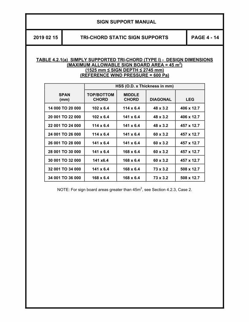
SIGN SUPPORT MANUAL
2019 02 15 TRI-CHORD STATIC SIGN SUPPORTS PAGE 4 - 14
TABLE 4.2.1(a) SIMPLY SUPPORTED TRI-CHORD (TYPE I) - DESIGN DIMENSIONS (MAXIMUM ALLOWABLE SIGN BOARD AREA = 45 m2)
(1525 mm ≤ SIGN DEPTH ≤ 2745 mm) (REFERENCE WIND PRESSURE = 600 Pa)
SPAN (mm)
HSS (O.D. x Thickness in mm) TOP/BOTTOM
CHORD MIDDLE CHORD
DIAGONAL
LEG
14 000 TO 20 000
102 x 6.4 114 x 6.4 48 x 3.2
406 x 12.7
20 001 TO 22 000
102 x 6.4 141 x 6.4 48 x 3.2
406 x 12.7
22 001 TO 24 000
114 x 6.4 141 x 6.4 48 x 3.2
457 x 12.7
24 001 TO 26 000
114 x 6.4 141 x 6.4
60 x 3.2
457 x 12.7
26 001 TO 28 000
141 x 6.4 141 x 6.4 60 x 3.2
457 x 12.7
28 001 TO 30 000
141 x 6.4 168 x 6.4 60 x 3.2
457 x 12.7
30 001 TO 32 000
141 x6.4 168 x 6.4 60 x 3.2
457 x 12.7
32 001 TO 34 000
141 x 6.4 168 x 6.4 73 x 3.2
508 x 12.7
34 001 TO 36 000
168 x 6.4 168 x 6.4 73 x 3.2
508 x 12.7
NOTE: For sign board areas greater than 45m2, see Section 4.2.3, Case 2.

SIGN SUPPORT MANUAL
2019 02 15 TRI-CHORD STATIC SIGN SUPPORTS PAGE 4 - 15
TABLE 4.2.1(b) SIMPLY SUPPORTED TRI-CHORD (TYPE II) DESIGN DIMENSIONS
(MAXIMUM ALLOWABLE SIGN BOARD AREA = 45 m2) (2745 mm < SIGN DEPTH ≤ 3965 mm)
(REFERENCE WIND PRESSURE = 600 Pa)
CLASS
SPAN (mm)
HSS (O.D. x Thickness in mm)
TOP/BOTTOMCHORD
MIDDLE CHORD
DIAGONAL
LEG
1 21 000 TO 26 000 114 x 6.4 141 x 6.4 73 x 4.8 508 x 12.7
2 26 001 TO 31 000 141 x 6.4 168 x 6.4 73 x 4.8 559 x 12.7
3 31 001 TO 36 000 168 x 6.4 168 x 6.4 73 x 6.4 559 x 12.7
NOTE: For sign board areas greater than 45m2, see Section 4.2.3, Case 2.
TABLE 4.2.1(c) CANTILEVER TRI-CHORD DESIGN DIMENSIONS (MAXIMUM ALLOWABLE SIGN BOARD AREA = 26.7 m2)
(1525 mm ≤ SIGN DEPTH ≤ 2745 mm) (REFERENCE WIND PRESSURE = 600 Pa)
CLASS
SPAN (mm)
HSS (O.D. x Thickness in mm)
TOP/BOTTOMCHORD
MIDDLE CHORD
DIAGONAL
LEG
1 UP TO 13 000 114 x 8 141 x 8 60 x 4.8 610 x 12.7
2 13 001 TO 14 500 141 x 8 141 x 8 60 x 4.8 660 x 12.7
3 14 501 TO 16 000 141 x 8 141 x 8 60 x 4.8 711 x 12.7
4 16 001 TO 18 000 141 x 8 141 x 8 60 x 6.4 762 x 12.7
SIGN SUPPORT MANUAL
2019 02 15 TRI-CHORD STATIC SIGN SUPPORTS PAGE 4 - 16
4.3 PREPARATION OF DRAWINGS
4.3.1 DATA REQUIRED
The sign support structure designer shall obtain information from the Regional Offices for the location, site number, span length, location, elevations and sizes of sign boards etc. of each sign support to be constructed. The designer shall prepare and complete the design standard drawings for the structures and its foundations that will be part of the contract documents. Design drawings shall show the following information. (1) A key plan, indicating the location of each support. (2) The Site number. (3) The span.
For simply supported type, the span is measured from centreline to centreline of legs.
For cantilever type, the span is measured from the centreline of the leg
to the tip at the free end of the top and bottom chords. (4) The control line or the centreline of the roadway, and the offset of the
left leg from the control line. (5) The elevation of the highest point on the roadway surface under the
sign support structure. (6) The dimension ‘H’ measured from the highest point on the roadway
surface to the centreline of the lowest chord of the Tri-Chord. For the simply supported Tri-Chord, this dimension shall be as indicated in Tables 4.1.5(a) & (b). For the cantilever Tri-Chord, dimension ‘H’ shall be calculated based on the clearance requirements stipulated in Section 4.1.5.
(7) The height of the supporting leg; that is, the dimension measured from
the top of footing to the centreline of the bottom chord. This dimension shall not exceed 6500 mm for simply supported Type I Tri-Chord or cantilever Tri-Chord and 7200 mm for simply supported Type II Tri-Chord.
(8) The top of footing elevation can differ for each leg of simply supported
type, if required. This elevation shall be determined so that the footing projection above finished grade around it is minimum 300 mm and

SIGN SUPPORT MANUAL
2019 02 15 TRI-CHORD STATIC SIGN SUPPORTS PAGE 4 - 17
maximum 1000 mm. This will give the designer flexibility to meet the structure leg height as stated in (7) above.
(9) The elevation of the ground-line at each footing. (10) The offset of each footing from the control line, either as a note or as a
dimension. (11) The Highway Station of the support structures on the designated
highway centreline or control line. (12) For simply supported type, a designation for each footing as a “Left
Footing” or “Right Footing”. Left and Right for this purpose are defined as if looking in the direction of the traffic, as shown in Figure 4.1.3(a).
(13) The footing type for each sign support footing (see Section 4.1.4). For
ground mounted footings, include the dimension ‘G’ from the rear face of the traffic protection barrier to the sign support footing (see Section 4.1.5).
(14) For each sign board, the following additional information is required:
- An outline in dashed lines showing each sign board to be mounted on the support structure,
- The dimensions B and D of each sign board, - The location of each sign board with respect to the centrelines of the
legs or, for simply supported type, left leg. 4.3.2 SIGN SUPPORT DRAWINGS
If the supports are to be supplied and erected as part of a contract, appropriate Standard Drawings from SS118-3, SS118-4, SS118-5, SS118-26, SS118-27, SS118-28, SS118-29, SS118-43, SS118-44 and SS110-45 must be used. Up to 10 sign supports can be detailed on one sheet.
The Appendix contains reduced size prints of these drawings, showing what information needs to be added. The Contract and W.P. numbers should be added to the title block. The sheet number is added when the drawings for the entire contract are assembled.
On Standard Drawings SS118-3, SS118-4, SS118-5, SS118-26, SS118-28 and SS118-43, there are tables to be completed on the drawings. In each table, one vertical column of data is used for each sign.

SIGN SUPPORT MANUAL
2019 02 15 TRI-CHORD STATIC SIGN SUPPORTS PAGE 4 - 18
The Standard Drawings shall be sealed, dated and signed according to Section 2.4.1.
Table 1 - General is to be completed with the following information:
(i) Station
(ii) Site Number
(iii) For simply supported type, the support span measured from centrelines of legs;
For cantilever type, the span measured from the centreline of leg to the tip at the free end of the top (bottom) chord
(iv) Truss depth measured centre to centre of top and bottom chords
(v) For simply supported Type II, the number of bays
(vi) For simply supported Type II, the bay length
(vii) Dimension ‘H’ from the centreline of the lowest chord to the highest point on the highway, including shoulders, curbs and median, as specified in Section 4.1.5
(viii) Local Reference Wind Pressure, in Pa
(ix) Maximum Allowable Sign Board Area, m2 (for simply supported type only)
(x) Sign Sizes (D x B) for each sign board (sign depth shall not exceed
the design limitation stipulated in Section 4.1.1)
(xi) The location of each sign board, Ei, with respect to the centreline of the leg (measured from left leg for simply supported type)
(xii) Elevation of the highest point on the highway under the signs, EL.HP, including shoulders, curbs, and medians
(xiii) Elevation at the top of support footing(s), EL.P1 (and EL.P2)
(xiv) Member outside diameters and thickness, as obtained from tabulated values in Table 4.2.1(a), 4.2.1(b) or 4.2.1(c)
(xv) Footing Type (see Section 4.1.4)

SIGN SUPPORT MANUAL
2019 02 15 TRI-CHORD STATIC SIGN SUPPORTS PAGE 4 - 19
Table 2 - Sign Board: Parts/Hardware is to be completed with quantities for all sign boards. This table shall also include the Z-bracket spacing. The following table shall be used for the calculation of quantities:
TABLE 4.3.2 PARTS & HARDWARE QUANTITIES
DESCRIPTION QUANTITY
12.7mm DIA. STAINLESS STEEL U-BOLT 2 per Z-Bracket
STAINLESS STEEL NYLON INSERT LOCK NUT 4 per Z-Bracket
STAINLESS STEEL WASHER 8 per Z-Bracket
PROFILED CHANNEL (C130x13) 2 per Z-Bracket
Z-BRACKET See Section 4.1.7
4.4 MAINTENANCE AND INSPECTION
All components must be inspected and maintained according to the requirements described in the Sign Support Inspection Guidelines, 2002. Long term durability of sign supports is dependent on routine maintenance and inspection. In order to prevent corrosion damage and fatigue problems to the base plate and the anchorage assembly, and to allow for proper inspection of the assembly, the following shall be ensured: (i) The base of the leg shall be kept free from dirt and debris (ii) The surrounding ground level shall be a minimum of 300 mm below the
top of the footing The base plate and weld connections shall be inspected regularly for fatigue cracking.
4.5 DESIGN INFORMATION
4.5.1 GENERAL
Calculations are based on Standard CAN/CSA-G40.20-13/G40.21-13 Grade 300W or ASTM A500 Grade C (or API-5L-X46 for round section of O.D. equal to or greater than 508 mm) structural steel, 30MPa concrete, and Grade 400W reinforcing steel for footings.

SIGN SUPPORT MANUAL
2019 02 15 TRI-CHORD STATIC SIGN SUPPORTS PAGE 4 - 20
The total weight of the sign board used in design is 0.169 kN/m2, including the self-weight of the standard aluminum ALCAN shape No.72838.
4.5.1.1 SIMPLY SUPPORTED TRI-CHORD For the simply supported type Tri-Chord, the design and detailing data conforms to the requirements of the 2014 edition of the CHBDC unless otherwise stated. Fatigue wind loads were obtained from AASHTO LFRD Specifications for Structural Supports for Highway Signs, Luminaires and Traffic Signals 1st Edition, 2015 with Interim Revisions, 2017.
4.5.1.2 CANTILEVER TRI-CHORD For the cantilever type Tri-chord, the design and detailing data conforms to the requirements of the 2006 edition of the CHBDC unless otherwise stated. Wind loads, design, and detailing for fatigue are in accordance with AASHTO Standard Specifications for Structural Supports for Highway Signs, Luminaires and Traffic Signals, 2013 unless otherwise stated. The natural wind gust pressure range for the fatigue design of the cantilever Tri-Chord support structures, as specified in AASHTO, is based on a yearly mean wind speed of 5 m/s (18 km/h). To account for the possibility of higher wind speed in some areas of Ontario, the thickness of the most critical member (middle chord) has been increased by one size beyond that required by design. The fatigue stress category for the connection between the cantilever chord and connection plate is not covered explicitly by the typical examples shown in the code. The Constant-Amplitude Fatigue Limits for this connection is assumed to be the average of the values for detail category E and E’. CHBDC has provisions for vortex shedding but these were not used since vortex shedding is not a fatigue load case, for these types of structures, according to AASHTO. In 2013, MTO retained The Boundary Layer Wind Tunnel Laboratory of the University of Western Ontario (UWO) to conduct wind tunnel testing for cantilever Tri-Chord sign support. The main objective of the study was to investigate the aerodynamic stability of the structures. A section model of the cantilever portion of the 18 m long cantilever Tri-Chord was constructed and tested in both smooth and turbulent flow conditions. The Static Section Model Tests indicated that cross-wind galloping oscillation is not likely to occur for the signage arrangements in the range of wind speeds studied. The Dynamic Section Model Tests showed that the sign structure is free of galloping instability up to a wind speed 38 m/s, which is about 25% greater than the

SIGN SUPPORT MANUAL
2019 02 15 TRI-CHORD STATIC SIGN SUPPORTS PAGE 4 - 21
design wind speed of 31 m/s (based on reference wind pressure of 600 Pa at a return period of 50 years) in Ontario. Based on these findings and advice from UWO, the galloping effect is not considered in the fatigue design of the structures. All information relating to this wind tunnel test, including conclusions and recommendations, are contained in the report – ‘A Study of Wind Effects for Cantilever Tri-Chord Sign Support Structures’.
4.5.2 DERIVATION OF DESIGN TABLES
The design dimensions for the Tri-Chord sign supports found in Tables 4.2.1(a), 4.2.1(b) and 4.2.1(c), were developed by determining the member responses under various design sign board areas, spans, and wind loads. Member responses were checked for ultimate, serviceability and fatigue limits states. Member sizes were optimised to limit the variety of section sizes.
4.5.3 DEFLECTIONS
The deflections for both vertical and horizontal members were limited to ensure adequate clearance for serviceability and aesthetic purposes. For the simply supported type Tri-Chord, the vertical members are restricted to 1% (LEG HEIGHT/100), and horizontal members are restricted to 2% (SPAN/50) lateral movement. Both limitations are within the suggested limits provided in AASHTO LRFD Specifications for Structural Supports for Highway Signs, Luminaires and Traffic Signals, 1st Edition, 2015 with Interim Revisions, 2017, which allows 2.5% lateral movement or 140' angular rotation from the centreline at the top of the structure in relation to the centreline at its base.
For the cantilever type Tri-Chord, the chords were cambered upwards to account for dead loads. The lateral displacement at the top of the leg due to wind load (SLS combination A1) is limited to 1.5% of the leg height. The lateral deflection at the tip of the arms due to the wind load (SLS combination A1) caused by bending of the leg and arms and twisting of the leg, is limited to 3% of the arm length. The vertical deflection at the tip of the arms due to truck gusts and natural wind, caused by bending of the leg and arm, is limited to 1.5% of the arm length. The limits for the cantilever Tri-Chord are within those specified by AASHTO Standard Specifications for Structural Supports for Highway Signs, Luminaires and Traffic Signals, 2013.
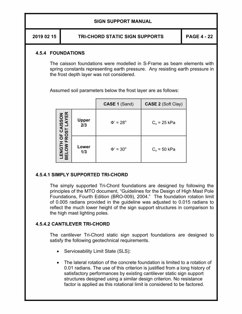
SIGN SUPPORT MANUAL
2019 02 15 TRI-CHORD STATIC SIGN SUPPORTS PAGE 4 - 22
4.5.4 FOUNDATIONS
The caisson foundations were modelled in S-Frame as beam elements with spring constants representing earth pressure. Any resisting earth pressure in the frost depth layer was not considered. Assumed soil parameters below the frost layer are as follows:
CASE 1 (Sand) CASE 2 (Soft Clay)
LE
NG
TH
OF
CA
ISS
ON
B
EL
OW
FR
OS
T L
AY
ER
Upper 2/3
Ф’ = 28o Cu = 25 kPa
Lower 1/3 Ф’ = 30o Cu = 50 kPa
4.5.4.1 SIMPLY SUPPORTED TRI-CHORD
The simply supported Tri-Chord foundations are designed by following the principles of the MTO document, “Guidelines for the Design of High Mast Pole Foundations, Fourth Edition (BRO-009), 2004.” The foundation rotation limit of 0.005 radians provided in the guideline was adjusted to 0.015 radians to reflect the much lower height of the sign support structures in comparison to the high mast lighting poles.
4.5.4.2 CANTILEVER TRI-CHORD
The cantilever Tri-Chord static sign support foundations are designed to satisfy the following geotechnical requirements.
Serviceability Limit State (SLS):
The lateral rotation of the concrete foundation is limited to a rotation of 0.01 radians. The use of this criterion is justified from a long history of satisfactory performances by existing cantilever static sign support structures designed using a similar design criterion. No resistance factor is applied as this rotational limit is considered to be factored.

SIGN SUPPORT MANUAL
2019 02 15 TRI-CHORD STATIC SIGN SUPPORTS PAGE 4 - 23
Ultimate Limit State (ULS):
i. The overturning analysis of the footing subjected to lateral
component of ULS loading uses the procedure described in the MTO document - “Guidelines for the Design of High Mast Pole Foundations, Fourth Edition (BRO-009), 2004”. A geotechnical resistance factor of 0.5 is used;
ii. The axial resistance of the shaft is checked against the vertical
component of ULS loading. The factored resistance is obtained from the summation of total shaft and toe resistances, multiplied by a geotechnical resistance factor of 0.3;
iii. The torsional resistance of the footing is checked against the
factored torsional moment, due to factored wind force of ULS combination A1 with a wind gust factor of 1.0, and a geotechnical resistance factor of 0.8 based on the following rationale/assumptions:
Torsional resistance check is consistent with the Illinois DOT’s Design
Guide on Shaft Overturning and Torsion Analysis (2011).
CHBDC doesn’t provide clear guidance for torsional resistance.
Wind gusts are excluded from torsional wind pressure loads, as they are intermittent and do not blow from the same direction all the time.
This design uses the highest wind pressure in Ontario in combination
with very weak soil parameters (sand or soft clay) for all locations.
Existing cantilever static sign support structures did not use torsion as a design criterion, and there is no report of torsional issues.
Geotechnical torsional failure will not reduce the geotechnical lateral
and axial resistances of the shaft.

SIGN SUPPORT MANUAL
2019 02 15 TRI-CHORD STATIC SIGN SUPPORTS PAGE 4 - 24
APPENDIX TO SECTION 4
TRI-CHORD STATIC SIGN SUPPORTS
FIGURE A4.1 Z-BRACKET DETAIL
FIGURE A4.2 ARROW BOARD DETAIL
SS118-3 STATIC SIGN SUPPORT - FOOTING DETAILS
(GROUND MOUNTED)
SS118-4 STATIC SIGN SUPPORT - FOOTING DETAILS (MEDIAN MOUNTED - SYMMETRICAL)
SS118-5 STATIC SIGN SUPPORT - FOOTING DETAILS
(MEDIAN MOUNTED - ASYMMETRICAL)
SS118-26 TRI-CHORD STATIC SIGN SUPPORT (TYPE I) GENERAL ARRANGEMENT
SS118-27 TRI-CHORD STATIC SIGN SUPPORT (TYPE I) STRUCTURE ASSEMBLY DETAILS
SS118-28 TRI-CHORD STATIC SIGN SUPPORT (TYPE II) GENERAL ARRANGEMENT
SS118-29 TRI-CHORD STATIC SIGN SUPPORT (TYPE II) STRUCTURE ASSEMBLY DETAILS SS118-43 CANTILEVER TRI-CHORD STATIC SIGN SUPPORT GENERAL ARRANGEMENT SS118-44 CANTILEVER TRI-CHORD STATIC SIGN SUPPORT STRUCTURE ASSEMBLY DETAILS I SS118-45 CANTILEVER TRI-CHORD STATIC SIGN SUPPORT STRUCTURE ASSEMBLY DETAILS II

SIGN SUPPORT MANUAL
2019 02 15 TRI-CHORD STATIC SIGN SUPPORTS PAGE 4 - 25
FIGURE A4.1 Z-BRACKET DETAIL

SIGN SUPPORT MANUAL
2019 02 15 TRI-CHORD STATIC SIGN SUPPORTS PAGE 4 - 26
FIGURE A4.2 ARROW BOARD DETAIL


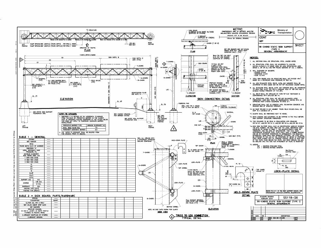


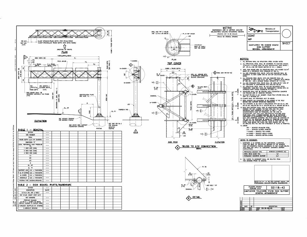


SIGN SUPPORT MANUAL
SECTION 5 – STEEL COLUMN SIGN SUPPORTS
THIS SECTION HAS BEEN REMOVED FROM THE MANUAL


SIGN SUPPORT MANUAL
SECTION 6 – TIMBER SIGN SUPPORTS
THIS SECTION HAS BEEN REMOVED FROM THE MANUAL


SIGN SUPPORT MANUAL
SECTION 7 – OVERHEAD MONOTUBE SIGN SUPPORTS
February 2019

SIGN SUPPORT MANUAL
2019 02 15 OVERHEAD MONOTUBE SIGN SUPPORTS PAGE 7 - 1
7 OVERHEAD MONOTUBE SIGN SUPPORTS
7.1 GENERAL
7.1.1 STANDARD SIGN SUPPORTS
Standard overhead monotube sign supports are used to support static lane-designation signs. The sign supports are fabricated in galvanized structural steel and designed to the requirements of the CAN/CSA-S6-06 (CHBDC). The sign supports contained in this Section are designed for sign boards and site conditions that meet the following criteria: (a) Maximum sign size to be 1.2 m by 1.2 m. (b) Supporting one under mounted sign or up to four evenly spaced front
mounted signs. (c) Design span length ranging from 13.5 m to and including 24.0 m. (d) Maximum allowable column height to be 7.7 m. Since members are
custom fabricated for each installation, any span-height combination is allowed.
(e) Reference wind pressure to be 600 Pa at a return period of 50 years. The effect of wind tunnelling as stated in CHBDC 3.10.1.2 is not considered.
(f) Competent soil conditions excluding rock fill. 7.1.2 TYPES OF SIGN SUPPORTS
There are two types of steel monotube overhead sign supports: TYPE I - Front Mounted Signs, Standard Drawing SS118-40:
For cases where the signs are to be viewed by traffic in one direction only. The signs are attached at their mid height to the horizontal support member.
TYPE II - Under Mounted Signs, Standard Drawing SS118-41: For cases where the sign is to be viewed by traffic in both directions, such as a single sign designating a "centre lane for left turns only". This type of sign is suspended below the level of the horizontal support member.
Figures 7.1.2(a) and (b) illustrate these types of sign support structures. Under mounted signs are more economically supported by cables suspended from guyed poles, rather than by horizontal support members, as illustrated in Figure 7.1.2(c). Therefore, the suspended cable/guyed pole arrangement should be specified, unless: (i) The standard monotube design is used for lane designation signs in
the same vicinity.

SIGN SUPPORT MANUAL
2019 02 15 OVERHEAD MONOTUBE SIGN SUPPORTS PAGE 7 - 2
(ii) Where the guying of poles is not practical. (iii) When the monotube support is preferable for aesthetic reasons, and
is approved by the Head, Regional Planning and Design.
7.1.3 LIMITATIONS
For economic and practical reasons these supports should be placed as close as possible to the edge of the travelled portion of the roadway (see Section 7.1.6). Therefore, these supports will probably be in the Clear Recovery Zone and should be protected, as discussed in Section 2.6. Under mounted signs should not be used in combination with front mounted signs. Each structure may support one under mounted sign or up to four front mounted signs. Unless protected from traffic, overhead monotube sign supports are limited to use on highways where the posted speed does not exceed 70 km/h.
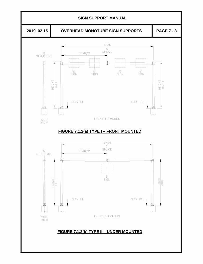
SIGN SUPPORT MANUAL
2019 02 15 OVERHEAD MONOTUBE SIGN SUPPORTS PAGE 7 - 3
FIGURE 7.1.2(a) TYPE I – FRONT MOUNTED
FIGURE 7.1.2(b) TYPE II – UNDER MOUNTED

SIGN SUPPORT MANUAL
2019 02 15 OVERHEAD MONOTUBE SIGN SUPPORTS PAGE 7 - 4
FIGURE 7.1.2(c) SIGN SUPPORT DETAILS

SIGN SUPPORT MANUAL
2019 02 15 OVERHEAD MONOTUBE SIGN SUPPORTS PAGE 7 - 5
7.1.4 DESCRIPTION OF SIGN SUPPORTS
The supports are made up of four tapered, octagonal, galvanized steel members. Each member tapers uniformly 280 mm to 190 mm, outside face, across flats.
There are three types of connections between sign support members:
i. Base Plate Connection - connecting the leg to the concrete footing.
ii. Corner Connection - connecting the horizontal support member to the legs.
iii. Mid-span Connection - connecting the two components of the
horizontal support member at or near midspan.
Each type of connection has been standardized for all spans in the allowable range, and no selection or additional data is necessary.
Signs are attached to supports by means of brackets welded to the horizontal support member.
Horizontal support members are fabricated with lugs along the centre line of the top surface for attaching the aerodynamic device to reduce the occurrences of wind induced vertical vibration.
7.1.5 FOOTINGS
Footings consist of reinforced concrete cast in augered holes. Details of footings are shown on the standard drawings.
The indicated footing depth is based on relatively competent soils of uniform composition. The soil types considered in the design were either cohesionless with a minimum angle of internal friction of 30º, or cohesive with a minimum shear strength of 50 kPa.
Encountered soil conditions such as rock fill, land fill, and soft material are not covered here, and require the footing to be designed by an Engineer.
7.1.6 CLEARANCE
The legs of the sign support structure should be located as close to the traffic barriers as possible, but the minimum horizontal clearance from the back of traffic protection barrier to the nearest face of sign support footing shall not be less than the values specified in Figure A3.2 (see Appendix 3 to Section 3).

SIGN SUPPORT MANUAL
2019 02 15 OVERHEAD MONOTUBE SIGN SUPPORTS PAGE 7 - 6
When the legs of sign support structures are not protected from traffic, they shall be located beyond the clear recovery zone, as specified in the Roadside Design Manual. The minimum vertical clearance from the highest point on the highway, including shoulders, curbs, and medians, to the bottom of a signboard shall not be less than 5300 mm, and not less than 5600 mm to the lowest structural member of the sign support structures, as specified in the MTO Design Supplement for TAC Geometric Design Guide for Canadian Roads, 2017.

SIGN SUPPORT MANUAL
2019 02 15 OVERHEAD MONOTUBE SIGN SUPPORTS PAGE 7 - 7
7.2 PREPARATION OF DRAWINGS
7.2.1 GENERAL
If the supply and erection of the support is to be part of the contract, Standard Drawings SS118-40 and/or SS118-41 and SS118-42 must be used.
7.2.2 DATA REQUIRED
The sign support structure designer shall obtain information from the Regional Offices for the location, site number, span length, location, elevations and sizes of sign boards etc. of each sign support to be constructed. The designer shall prepare and complete the design standard drawings for the structures and its foundations that will be part of the contract documents. Design drawings shall show the following information. (i) A key plan, indicating the approximate location of each support.
(ii) The Site number.
(iii) The support span, measured from centreline to centreline of leg;
should be rounded up to the nearest half metre unless there is a restriction on the leg location.
(iv) The control line of the roadway and the offset of the leg from the control line.
(v) The elevation of the highest point on the roadway surface under the
support structure.
(vi) The location, size, and type of the signs with a clear indication as to whether front mounted signs or a single under mounted sign shall be installed. This information should be shown on a working print since it is not needed on the contract drawings. The vertical and horizontal dimensions of each sign must be shown together with the distance from the centreline of the signs to the centreline of the leg. If the signs are to carry directional arrows, these should be shown diagrammatically on the drawing.
(vii) The vertical dimension measured from the highest point on the
roadway surface to the lowest bottom edge of the signs. This is normally 5300 mm but may be slightly more in order to allow for a future change in pavement elevation.

SIGN SUPPORT MANUAL
2019 02 15 OVERHEAD MONOTUBE SIGN SUPPORTS PAGE 7 - 8
(viii) The elevation of the ground line at each footing.
(ix) The top of footing elevation. The footings must be no more than
200 mm above the finished grade for safety reasons, nor less than 75 mm to ensure drainage.
(x) The offset of the centreline of footing from the control line, either as
note or as a dimension.
(xi) The station of the support structure on a designated highway centreline or control line.
(xii) A designation for each footing as a “Left footing” or “Right footing”.
Left and Right for this purpose are defined as if looking in the direction of the traffic that will be viewing the signs. All elevations of the support should be marked “FRONT VIEW” and must be drawn accordingly, with the right footing on the right, etc. When a sign, or signs, on the support are to be read from either side, that is, traffic travelling in both directions passes under the support structure, the view should be drawn looking in the direction of increasing chainage. This should be noted under the title of “FRONT VIEW”. In such cases, the footings should also be marked with reference to the north point as a check.
(xiii) Unusual requirements must be clearly noted; for example, “front
mounted” signs which are to be on the back of the support, or signs which are to be asymmetrically positioned in relation to the horizontal centreline.

SIGN SUPPORT MANUAL
2019 02 15 OVERHEAD MONOTUBE SIGN SUPPORTS PAGE 7 - 9
7.2.3 STRUCTURE DRAWINGS
There are three Standard Drawings for these supports; the Appendix contains reduced size prints of these Standard Drawings, showing what information needs to be added. The Contract and W.P. numbers should be added to the title block. The sheet number is added when the drawings for the entire contract are assembled. Up to 6 sign supports can be detailed on one sheet. Standard Drawing SS118-40 is for supports carrying front mounted signs. All required data in the tables could generally be obtained directly from the key plan and frame dimension drawing described earlier. The “MESSAGE” column is to show diagrammatically the sign content, such as direction arrows, for the information of the District staff, because the signs are not included in the contracts. The column height is measured from the top of footing to the top of column. Standard Drawing SS118-41 is for supports carrying an under mounted sign to be seen from either traffic direction. The signboard and the splice joint are generally located at or very close to the middle of the span. There is only one table to be filled in the standard drawing to show all the design information of the sign support structure. The MESSAGE, however, contains two columns to show the content at the front and the rear of the signboard. When the highway layout is simple, the location of the supports and their footings can be shown adequately on the standard drawing. In this case, it is not necessary to make the key plan and frame dimension drawing part of the contract documents. If this is not the case, add a note referring to that drawing, and cross out the location sketch and the X and Y columns on the standard. The Standard Drawings shall be sealed, dated, and signed according to Section 2.4.1.
7.3 MAINTENANCE AND INSPECTION
All components shall be inspected and maintained according to the “Sign Supports Inspection Guideline”. Long-term durability of sign supports is dependent on routine maintenance and inspection. In order to prevent corrosion damage and fatigue problems to the anchorage assembly, the following shall be ensured:

SIGN SUPPORT MANUAL
2019 02 15 OVERHEAD MONOTUBE SIGN SUPPORTS PAGE 7 - 10
(i) The base of the vertical support leg shall be kept free from dirt and debris
(ii) The base plate and arm connection welds shall be inspected regularly for fatigue cracking
(iii) The anchor bolts connection shall be checked periodically for tightening
7.4 DESIGN INFORMATION
Design and detailing data contained in this Section conforms to the requirements of the Canadian Highway Bridge Design Code CAN/CSA-S6-06 unless otherwise stated. Calculations are based on Standard CAN/CSA-G40.20-13/G40.21-13 Grade 300W for structural steel, 30 MPa for concrete, and Grade 400W reinforcing steel for footings. Dead load deflection is compensated by cambering the horizontal support as shown in the drawing. Fatigue wind loads are obtained from AASHTO – Standard Specifications for Structural Supports for Highways Signs, Luminaires and Traffic Signals, 4th Edition, 2001. It is based on NCHRP Report 412, “Fatigue Resistance Design of Cantilever Signal, Sign and Light Supports”. A baffle plate is mounted on top of the centreline of the Monotube sign support in order to minimize the dynamic effects of across-wind loads induced by vortex shedding excitation.
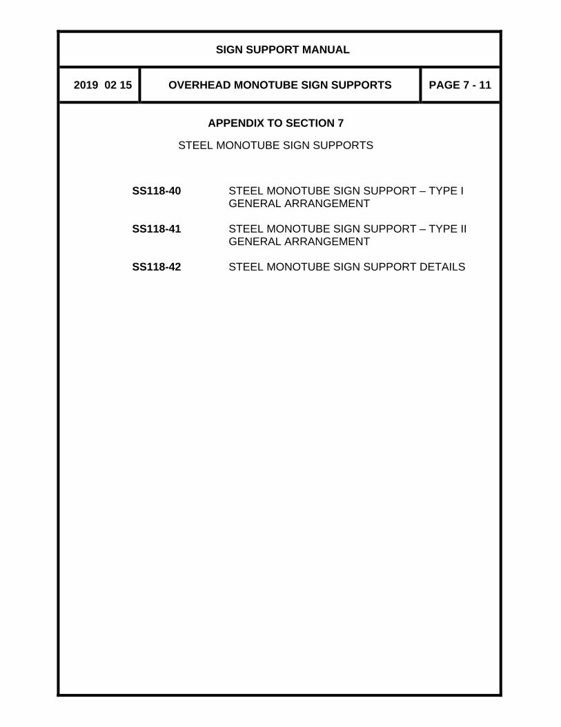
SIGN SUPPORT MANUAL
2019 02 15 OVERHEAD MONOTUBE SIGN SUPPORTS PAGE 7 - 11
APPENDIX TO SECTION 7
STEEL MONOTUBE SIGN SUPPORTS
SS118-40 STEEL MONOTUBE SIGN SUPPORT – TYPE I GENERAL ARRANGEMENT
SS118-41 STEEL MONOTUBE SIGN SUPPORT – TYPE II
GENERAL ARRANGEMENT SS118-42 STEEL MONOTUBE SIGN SUPPORT DETAILS

This page is intentionally left blank


This page is intentionally left blank.
SIGN SUPPORT MANUAL
SECTION 8 – VARIABLE MESSAGE SIGN SUPPORTS
February 2019


SIGN SUPPORT MANUAL
2019 02 15 VARIABLE MESSAGE SIGN (VMS) SUPPORTS PAGE 8 - 1
8 VARIABLE MESSAGE SIGN (VMS) SUPPORT 8.1 GENERAL 8.1.1 STANDARD SIGN SUPPORTS 8.1.1.1 VMS OVERHEAD TRUSS
Standard VMS overhead truss sign supports are used to support VMS systems. The overhead truss is fabricated in aluminum, and the vertical support legs in galvanized structural steel. They are designed to the requirements of the CSA S6-14 (CHBDC). The sign supports contained in this Section are designed for VMS components and site conditions that meet the following criteria: (a) Spans from 17592 to 34000 mm. (b) Maximum total sign area of 40 square metres for a reference wind
pressure of 600 Pa at a return period of 50 years. The effect of wind funnelling due to special topographical features such as deep valleys is not considered (CHBDC 3.10.1.2).
(c) Overall depth of sign component of 3075 mm. (d) Overall width of sign component of 13220 mm. (e) Maximum weight of sign component is 5000 kg. (f) Location of supports and vertical clearances according to the
requirements of the CHBDC and MTO Design Supplement for TAC Geometric Design Guide for Canadian Roads (2017).
(g) Competent soil conditions (as described in Section 8.5.4) excluding
rock fill. 8.1.1.2 POLE MOUNTED VMS
Pole mounted VMS supports are used to support portable type VMS boards. The sign supports are fabricated in structural steel, and designed to the requirement of the CSA-S6-14 (CHBDC). The supports are designed for VMS components and site conditions that meet the following criteria:
SIGN SUPPORT MANUAL
2019 02 15 VARIABLE MESSAGE SIGN (VMS) SUPPORTS PAGE 8 - 2
(a) Maximum sign board area of 15 square metres for a reference wind
pressure up to 600 Pa at a return period of 50 years. (b) Maximum depth of sign component of 3000 mm. (c) Maximum width of sign component of 5000 mm.
(d) Maximum weight of sign component of 1000 kg. (e) Location of supports and vertical clearances according to the
requirements of the CHBDC and MTO Design Supplement for TAC Geometric Design Guide for Canadian Roads, 2017.
(f) Competent soil conditions (as described in Section 8.5.4) excluding
rock fill. 8.1.2 LIMITATIONS
For economic and practical reasons, these supports should be placed as close as possible to the edge of the travelled portion of the highway. Therefore, the supports will probably be in the clear recovery zone and should be protected as discussed in Section 2.6. They could also be located on median barriers. For ground mounted footings, the top of footing elevation shall be a minimum of 300 mm above the finished grade. This could be increased up to 1000 mm in order to limit the leg height. The dimensions from the top of the footing to the centreline of the VMS overhead truss shall not exceed 7500 mm, and to the bottom of portable VMS board shall not exceed 6500 mm.
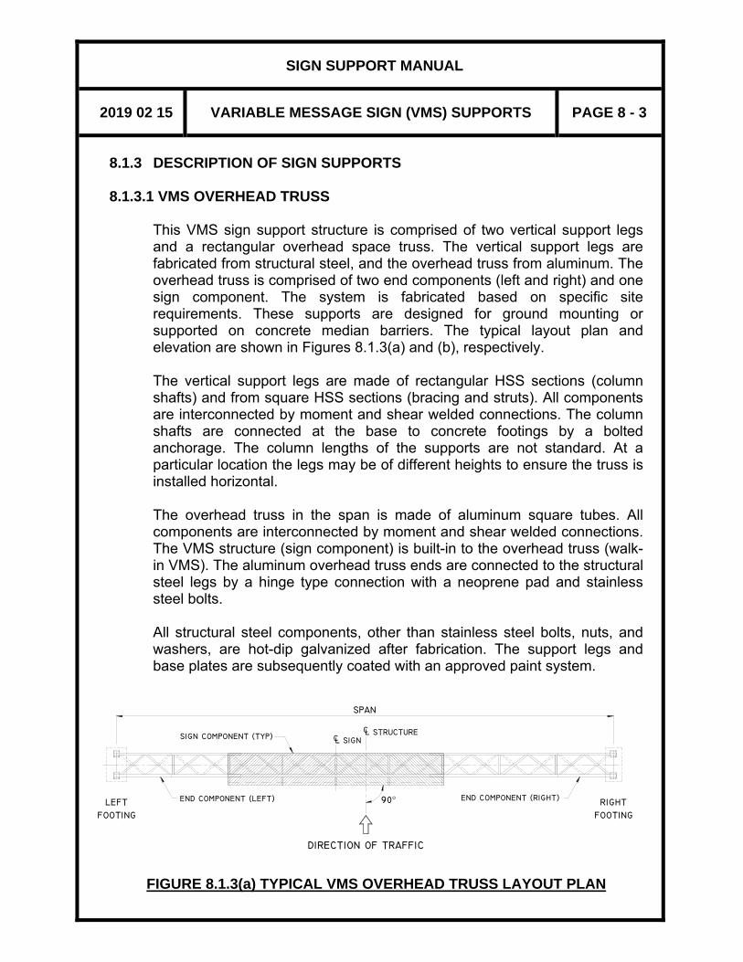
SIGN SUPPORT MANUAL
2019 02 15 VARIABLE MESSAGE SIGN (VMS) SUPPORTS PAGE 8 - 3
SIGN COMPONENT (TYP)
END COMPONENT (LEFT)
FOOTING
LEFT END COMPONENT (RIGHT)
C
SPAN
CL SIGN
90°
L STRUCTURE
FOOTING
RIGHT
DIRECTION OF TRAFFIC
8.1.3 DESCRIPTION OF SIGN SUPPORTS
8.1.3.1 VMS OVERHEAD TRUSS
This VMS sign support structure is comprised of two vertical support legs and a rectangular overhead space truss. The vertical support legs are fabricated from structural steel, and the overhead truss from aluminum. The overhead truss is comprised of two end components (left and right) and one sign component. The system is fabricated based on specific site requirements. These supports are designed for ground mounting or supported on concrete median barriers. The typical layout plan and elevation are shown in Figures 8.1.3(a) and (b), respectively. The vertical support legs are made of rectangular HSS sections (column shafts) and from square HSS sections (bracing and struts). All components are interconnected by moment and shear welded connections. The column shafts are connected at the base to concrete footings by a bolted anchorage. The column lengths of the supports are not standard. At a particular location the legs may be of different heights to ensure the truss is installed horizontal. The overhead truss in the span is made of aluminum square tubes. All components are interconnected by moment and shear welded connections. The VMS structure (sign component) is built-in to the overhead truss (walk-in VMS). The aluminum overhead truss ends are connected to the structural steel legs by a hinge type connection with a neoprene pad and stainless steel bolts. All structural steel components, other than stainless steel bolts, nuts, and washers, are hot-dip galvanized after fabrication. The support legs and base plates are subsequently coated with an approved paint system.
FIGURE 8.1.3(a) TYPICAL VMS OVERHEAD TRUSS LAYOUT PLAN

SIGN SUPPORT MANUAL
2019 02 15 VARIABLE MESSAGE SIGN (VMS) SUPPORTS PAGE 8 - 4
(TYP.)
SIG
N C
OMPONENT (TYP.)
13092
LEFT
FOOTIN
GRIG
HT
FOOTIN
G
SPAN
SIG
N C
OMPONENT (TYP.)
END C
OMPONENT (LEFT)
END C
OMPONENT (RIG
HT)
E (LEFT)
E (RIG
HT)
5600 MIN.
(TYP.)
2916
L S
TRUCTURE
C
MAX. 7500
G
EL.P
2
(TYP.)
EQUALLY SPACED PANELS
EL. P1
VERTICAL CLEARANCE
EL. HP
C L S
IGN
FIG
UR
E 8.
1.3(
b) T
YPIC
AL
VMS
OVE
RH
EAD
TR
USS
SU
PPO
RT
ELEV
ATI
ON

SIGN SUPPORT MANUAL
2019 02 15 VARIABLE MESSAGE SIGN (VMS) SUPPORTS PAGE 8 - 5
8.1.3.2 POLE MOUNTED VMS This sign support is fabricated from structural steel and comprise a single vertical pole. It is designed for ground mounting or supported on concrete median barriers. The typical layout plan and sign support elevation are shown in Figures 8.1.3(c) and (d) respectively. The vertical support member is straight and made from round HSS or octagonal shape sections. Fabricators may choose to fabricate the octagonal shape from steel plate. Octagonal sections have to meet the requirements shown on Standard Drawings SS118-11 and SS118-13. The maximum allowable length of the vertical support, assumed in design, is 8750 mm. It is connected at the base to a concrete footing by a bolted anchorage system. The VMS board is mounted to the pole by means of hot-dip galvanized steel brackets attached to the pole. The location and connection details are required to be designed by Fabricator to suit the type of VMS selected. All structural steel components, other than stainless steel bolts, nuts, and washers, are hot-dip galvanized after fabrication. The pole and base plate are subsequently coated with an approved paint system.

SIGN SUPPORT MANUAL
2019 02 15 VARIABLE MESSAGE SIGN (VMS) SUPPORTS PAGE 8 - 6
FIGURE 8.1.3(c) TYPICAL POLE MOUNTED VMS LAYOUT PLAN
FIGURE 8.1.3 (d) TYPICAL POLE MOUNTED VMS SUPPORT ELEVATION
SIGN SUPPORT MANUAL
2019 02 15 VARIABLE MESSAGE SIGN (VMS) SUPPORTS PAGE 8 - 7
8.1.4 FOOTINGS Each sign support footing consists of a single reinforced concrete caisson. Details differ according to their location, and generally are of two types, as shown on the standard drawings: ground mounted and median mounted. (see Standard Drawings SS118-3, SS118-4, and SS118-5 for pole mounted VMS supports; SS118-6, SS118-7, and SS118-8 for VMS overhead truss supports). The indicated footing depths are the minimum required for each support. Footing proportions apply to competent soil conditions of uniform composition. Parameters upon which the design is based are given in Section 8.5.4. Encountered soil conditions such as rock fill, land fill, and soft material are not covered here and require the footing to be designed by an Engineer.
8.1.5 CLEARANCE For ground mounted footings, the minimum horizontal clearance ‘G’ from the back of traffic protection barrier to the nearest face of sign support footing shall not be less than the values specified in Figure A3.2 (see Appendix to Section 3). The minimum vertical clearance from the bottom of the sign component to the highest point on the highway, including shoulders, curbs, and medians, shall not be less than 5600 mm for VMS overhead truss, and 5300 mm for pole mounted VMS under dead load deflection.
8.1.6 SUPPLY AND ERECTION For a temporary installation, a Tri-Chord overhead truss (Section 4) with the same span as a prospective VMS truss structure could be mounted on the VMS support legs. A connection detail for this assemblage is shown on Standard Drawing SS118-36. Construction shall meet the requirements of OPSS 915, Construction Specification for Sign Support Structures, and associated Special Provisions. Each sign support structure shall have a corrosion-protected identification plate showing the site number (formerly structure ID number), the manufacturer’s name or the trademark, and the date of manufacture.
SIGN SUPPORT MANUAL
2019 02 15 VARIABLE MESSAGE SIGN (VMS) SUPPORTS PAGE 8 - 8
8.2 PROCEDURES
8.2.1 GENERAL The sign support structures are fabricated from shop drawings based on the standard drawings on a site-specific basis. The design of the VMS overhead sign support structure is based on a reference wind pressure of 600 Pa. The geometric layout of the overhead truss shall depend on the location of the sign component along the span of the structure, in relation to the travelled portion of the highway (see Standard Drawing SS118-36). Multiple combinations of end components (left/right) and sign components can be obtained, as shown in Figure 8.2.1. The length of panel for the end components will vary, within certain limits, in every structure. The length of panel for the sign component is fixed. Design dimensions (structural sections) for end and sign components are fixed, and are given on the Standard Drawings SS118-37 and SS118-38. The design of the pole mounted VMS support is based on a reference wind pressure of 600 Pa. Design dimensions are given on the Standard Drawings SS118-11 and SS118-13.
8.2.2 DATA REQUIRED For each VMS sign support, the following data is required:
(1) The span (for overhead truss). (2) The site location and Site Number of the structure. For a proposed
highway or a highway under reconstruction, the location should be specified as a station.
(3) The location of the sign component along the longitudinal centreline
of the structure (for overhead truss). (4) The elevation of the highest point on the highway under the sign
component, and the final ground elevations under the sign structure.
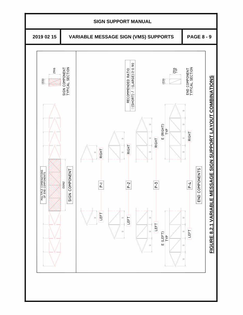
SIGN SUPPORT MANUAL
2019 02 15 VARIABLE MESSAGE SIGN (VMS) SUPPORTS PAGE 8 - 9
FIG
UR
E 8.
2.1
VAR
IAB
LE M
ESSA
GE
SIG
N S
UPP
OR
T LA
YOU
T C
OM
BIN
ATI
ON
S
E (LEFT)
TYP LEFT
P−3
RIG
HT
LEFT
TYPI C
AL S
ECTIO
NSIG
N C
OMPONENT
1330
RECOMMENDED R
ATIO
(S
HORT)
(L
ARGE) 0.9
0
SIG
N C
OMPONENT
MULTIP
LE C
OMBIN
ATIO
NS
LEFT
LEFT
OF E
ND C
OMPONENTS
13092
P−1
P−2
RIG
HT
RIG
HT
/
2916
END C
OMPONENT
TYPIC
AL S
ECTI O
N
1330
END C
OMPONENTS
P−4
RIG
HT
E (RIG
HT)
TYP
2916
TYP

SIGN SUPPORT MANUAL
2019 02 15 VARIABLE MESSAGE SIGN (VMS) SUPPORTS PAGE 8 - 10
8.2.3 PROCEDURE FOR DESIGN OF VMS SIGN SUPPORT STRUCTURES CASE 1 – VMS OVERHEAD TRUSS GIVEN: SPAN AND LOCATION OF SIGN COMPONENT Example: a span of 27990 mm, and a distance of 12138 mm from
the centreline of the left leg to the centreline of the sign component.
STEP 1: OBTAIN THE LENGTH OF THE END COMPONENTS. E.g., The distance between centreline of end verticals of the sign
component is 13092 mm. The sign component is centered at 12138 mm from the left leg. Therefore, the dimension from the centreline of the left leg to the left end vertical of the sign component, E(LEFT), is equal to 12138-13092/2 = 5592 mm. Based on the given span, E(RIGHT) is equal to 27990 – 13092 – 5592 = 9306 mm.
STEP 2: OBTAIN THE LENGTH OF PANELS The number of panels for each end component should be kept to
a minimum. The length of the panel, b, for a given end component shall be a constant value, and within the following limits: 2250 ≤ B ≤ 3600 mm.
E.g., B (LEFT) = 5592/2 = 2796 mm, and B (RIGHT) = 9306/3 = 3102 mm.
STEP 3: CHECK BOUNDARY CONDITIONS
(a) The maximum length of the vertical support leg from the
top of the footing to the centreline of the overhead truss shall be 7500 mm.
(b) The dimension measured from the highest point on the
highway, EL.HP, to the bottom of the sign component shall be equal to or greater than 5600 mm.
(c) For static and aesthetic reasons, the ratio between the
length of panel in both end components should be kept as close to 1 as possible. The minimum recommended value is 0.9. A minor relocation of the sign component may be required.
E.g., 2796/3102 = 0.9
STEP 4: COMPLETE THE STANDARD DRAWINGS Refer to 8.3 for Preparation of Drawings.

SIGN SUPPORT MANUAL
2019 02 15 VARIABLE MESSAGE SIGN (VMS) SUPPORTS PAGE 8 - 11
CASE 2 – POLE MOUNTED VMS GIVEN: VMS SIZE AND LOCATION OF SIGN COMPONENT Example: 4000 mm x 2200 mm VMS board. STEP 1: CHECK BOUNDARY CONDITIONS
(a) The maximum length of the vertical support leg from the top of the footing to the bottom of VMS board shall not exceed 6500 mm.
(b) The dimension measured from the highest point on the
highway, EL.HP, to the bottom of the sign component shall be equal to or greater than 5300 mm.
If any of the above conditions are not satisfied, the initial design parameters must be revised.
STEP 2: COMPLETE THE STANDARD DRAWINGS Refer to Section 8.3 for Preparation of Drawings.
8.3 PREPARATION OF DRAWINGS 8.3.1 DATA REQUIRED
The sign support structure designer shall obtain information from the Regional Offices for the location, site number, span length, location, elevations and sizes of sign boards etc. of each sign support to be constructed. The designer shall prepare and complete the design standard drawings for the structures and its foundations that will be part of the contract documents. Design drawings shall show the following information. (1) A key plan, indicating the location of each support. (2) The Site Number. (3) The support span measured from centreline to centreline of leg (for
overhead truss) (4) The control line or the centreline of the roadway, and the offset of the
left leg from the control line.

SIGN SUPPORT MANUAL
2019 02 15 VARIABLE MESSAGE SIGN (VMS) SUPPORTS PAGE 8 - 12
(5) The elevation of the highest point on the roadway surface under the support structure.
(6) The dimension measured from the highest point (EL.HP) on the
roadway surface to the bottom of the sign component. This height shall not be less than 5600 mm for overhead truss and 5300 mm for pole mounted VMS.
(7) The dimensions from the top of the footing (EL.P1 or EL.P2) to the
centreline of the VMS overhead truss shall not exceed 7500 mm, and to the bottom of portable VMS board shall not exceed 6500 mm
(8) The top of footing elevation can differ for each leg, if required. This
elevation shall be determined so that the footing projection above finished grade around it is minimum 300 mm and maximum 1000 mm. This will give the designer flexibility to meet the structure leg height as stated in (7) above.
(9) The elevation of the ground line at each footing. (10) The offset of the centreline of each footing from the control line,
either as a note or as a dimension. (11) The station of the support structure on a designated highway
centreline or control line. (12) A designation for each footing as a “Left Footing” or “Right Footing”.
Left and Right for this purpose are defined as if looking in the direction of the traffic, as shown in Figure 8.1.3(a).
(13) The footing type for each sign support footing (see Section 8.1.4).
For ground mounted footings, the dimension ‘G’ from the front face of the traffic protection barrier to the leg or the footing, whichever is closer (see Section 8.1.5).
(14) For the sign component, the following additional information is
required: - An outline in dashed line showing the sign component, - The requested location of the sign component with respect to the
centreline of the left column.
SIGN SUPPORT MANUAL
2019 02 15 VARIABLE MESSAGE SIGN (VMS) SUPPORTS PAGE 8 - 13
8.3.2 SIGN SUPPORT DRAWINGS If the supports are to be supplied and erected as part of a contract, the following Standard Drawings must be used: SS118-11, SS118-13, SS118-36, SS118-37 or SS118-38 for the structure; SS118-3, SS118-4, SS118-5, SS118-6, SS118-7 or SS118-8 for the footings. Up to 10 sign supports can be detailed on one sheet. The Appendix contains reduced prints of these drawings, showing what information needs to be added. The Contract and W.P. numbers should be added to the title block. The sheet number is added when the drawings for the entire contract are assembled. On Standard Drawings SS118-11, SS118-13, and SS118-36, there is a table to be completed on the drawing. In the table, one vertical column of data is used for each sign. The Standard Drawings shall be sealed, dated and signed according to 2.4.1. The data required to complete Table 1 on Standard Drawing SS118-36 consists of the following: (i) Station (ii) Site Number (iii) The support span measured from centrelines of support legs (iv) Truss Diagram. The electronic file of the Standard Drawing
SS118-36 contains schematic sign and end components drawn on the left border that shall be used to fill this box.
(v) End Component (Left): Type of Panel (P-1, P-2, P-3 or P-4) E (LEFT): dimension from centreline of left column to left end vertical of sign component. B (LEFT): length of panel
End Component (Right): Type of Panel (P-1, P-2, P-3 or P-4) E (RIGHT): dimension from centreline of right column to right end vertical of sign component. B (RIGHT): length of panel
(vi) Elevation of the highest point on the highway under the sign, including shoulders, curbs and median, EL.HP
(vii) Elevation at top of the left support footing, EL.P1 (viii) Elevation at top of the right support footing, EL.P2 (ix) Door Side (Left/Right).

SIGN SUPPORT MANUAL
2019 02 15 VARIABLE MESSAGE SIGN (VMS) SUPPORTS PAGE 8 - 14
(x) Left Footing Type (see Section 8.1.4) (xi) Right Footing Type (see Section 8.1.4) The data required to complete Table 1 on Standard Drawings SS118-11 and SS118-13 consist of the following: (i) Frost Depth; may be obtained from Appendix to Section 2 in this
manual if the recommendations of a geotechnical engineer are not available
(ii) Station (iii) Site Number (iv) Sign Size (DxB) (v) Footing Type (see Section 8.1.4) (vi) Dimension between top of footing and bottom of sign board, HL (vii) Barrier to support clearance, G (see Section 8.1.5) (viii) Elevation at top of the support footing, EL.P1 (ix) Elevation of the highest point on the highway under the sign,
including shoulders, curbs, and median, EL.HP 8.4 MAINTENANCE AND INSPECTION
All components must be properly inspected and maintained according to the requirements described in the Sign Support Inspection Guidelines, 2002. Long term durability of sign supports is dependent on routine maintenance and inspection. In order to prevent corrosion damage and fatigue problems to the base plate and the anchorage assembly, and to allow for proper inspection of the assembly, the following shall be ensured: (i) The base of the vertical support leg shall be kept free from dirt and
debris. (ii) The top of the footing shall be a minimum of 300 mm above the
ground surrounding it. (iii) The connection welds shall be inspected regularly for fatigue
cracking. Check tightening of connection and anchor bolts periodically.

SIGN SUPPORT MANUAL
2019 02 15 VARIABLE MESSAGE SIGN (VMS) SUPPORTS PAGE 8 - 15
8.5 DESIGN INFORMATION 8.5.1 GENERAL
Design and detailing data for the VMS Overhead Truss and the Pole Mounted VMS contained in this Section conforms to the requirements of the CSA-S6-14 (CHBDC).
Properties for structural materials used in calculations are based on Standard CSA-G40.20-13/G40.21-13 Grade 300W or 350W structural steel, Alloy 6061-T6 aluminum extruded tube and plates, 30 MPa concrete, and Grade 400W reinforcing steel for footings, as stipulated in the Standard Drawings. The maximum weight of the overhead sign component, which includes the self-weight of the aluminum truss, shall not exceed 5000 kg. The maximum weight of the portable VMS board shall not exceed 1000 kg. In the VMS overhead truss, all bolts, nuts, and washers shall be stainless steel and conform to ASTM F593 Alloy 304, with a minimum yield of 480 MPa and a minimum tensile strength of 715 MPa. In the pole mounted VMS, all bolts, nuts, and washers shall conform to ASTM F3125/F3125M and be hot-dip galvanized in accordance with OPSS 911. Wind loads, design, and detailing for fatigue were in accordance with AASHTO LRFD Specifications for Structural Supports for Highway Signs, Luminaries and Traffic Signals, 2015, including the 2017 Interim Revisions, unless otherwise stated.
8.5.2 DESIGN DIMENSIONS
The design dimensions for the VMS overhead truss sign supports found in the Standard Drawings were developed by determining the member responses under various design spans and wind loads. Member responses were checked for ultimate, serviceability, and fatigue limit states.
8.5.3 DEFLECTIONS The deflections for both vertical and horizontal members of the VMS overhead truss support system are limited for clearance concerns as well as for aesthetic purposes. The vertical deflection of horizontal supports are limited to 1% (L/100), and horizontal deflection of vertical supports were restricted to 2% (L/50). Both limitations are well within the suggested limits provided in AASHTO's "LFRD Specifications for Structural Supports for

SIGN SUPPORT MANUAL
2019 02 15 VARIABLE MESSAGE SIGN (VMS) SUPPORTS PAGE 8 - 16
Highway Signs, Luminaries and Traffic Signals", 2015, which allows 2.5% lateral movement or 1º40' angular rotation from the centreline at the top of the structure in relation to the centreline at its base. The maximum lateral deflection of the pole mounted VMS due to wind load has been limited to 1.5% of pole height. The lateral deflection of the concrete foundation has been limited to an instantaneous rotation of 0.01 radians (0º30’) under wind load.
8.5.4 FOUNDATIONS The caisson foundations were modelled in S-Frame as beam elements with spring constants representing earth pressure. Springs constants in the dead load direction (for sustained load) were assumed to be 1/3 the value of those in the live load direction (for instantaneous load). Any resisting earth pressure in the frost depth layer was discounted. Assumed soil parameters below the frost layer are as follows:
CASE 1 (Sand) CASE 2 (Soft Clay)
LEN
GTH
OF
CA
ISSO
N
BEL
OW
FR
OST
LA
YER
Upper 2/3 Ф’ = 28 o Cu = 25 kPa
Lower 1/3 Ф’ = 30 o Cu = 50 kPa

SIGN SUPPORT MANUAL
2019 02 15 VARIABLE MESSAGE SIGN (VMS) SUPPORTS PAGE 8 - 17
APPENDIX TO SECTION 8
VARIABLE MESSAGE SIGN SUPPORTS
SS118-6 VARIABLE MESSAGE SIGN (VMS) SUPPORT
FOOTING DETAILS (GROUND MOUNTED)
SS118-7 VARIABLE MESSAGE SIGN (VMS) SUPPORT – FOOTING DETAILS (MEDIAN MOUNTED – SYMMETRICAL)
SS118-8 VARIABLE MESSAGE SIGN (VMS) SUPPORT –
FOOTING DETAILS (MEDIAN MOUNTED – ASYMMETRICAL)
SS118-11 POLE MOUNTED VARIABLE MESSAGE SIGN SUPPORT
GENERAL ARRANGEMENT (GROUND MOUNTED)
SS118-13 POLE MOUNTED VARIABLE MESSAGE SIGN SUPPORT GENERAL ARRANGEMENT (MEDIAN MOUNTED)
SS118-36 VARIABLE MESSAGE SIGN (VMS) SUPPORT
GENERAL ARRANGEMENT
SS118-37 VARIABLE MESSAGE SIGN (VMS) SUPPORT END COMPONENT - DETAILS
SS118-38 VARIABLE MESSAGE SIGN (VMS) SUPPORT
SIGN COMPONENT - DETAILS
NOTE:
See Appendix to Section 4 for reduced size prints of the following Standard Drawings for the Pole Mounted VMS support footing details.
SS118-3 STATIC SIGN SUPPORT - FOOTING DETAILS
(GROUND MOUNTED)
SS118-4 STATIC SIGN SUPPORT - FOOTING DETAILS (MEDIAN MOUNTED – SYMMETRICAL)
SS118-5 STATIC SIGN SUPPORT - FOOTING DETAILS
(MEDIAN MOUNTED – ASYMMETRICAL)

This page is intentionally left blank.


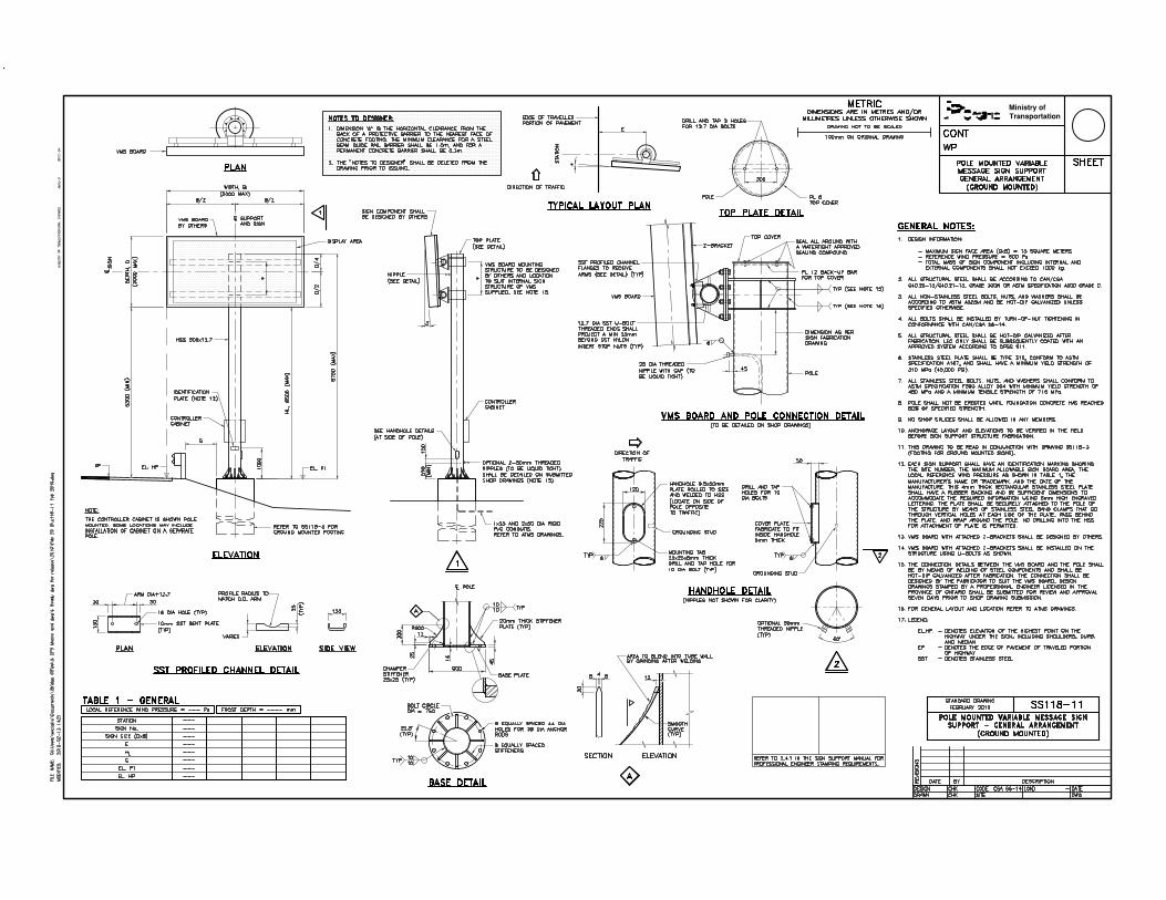


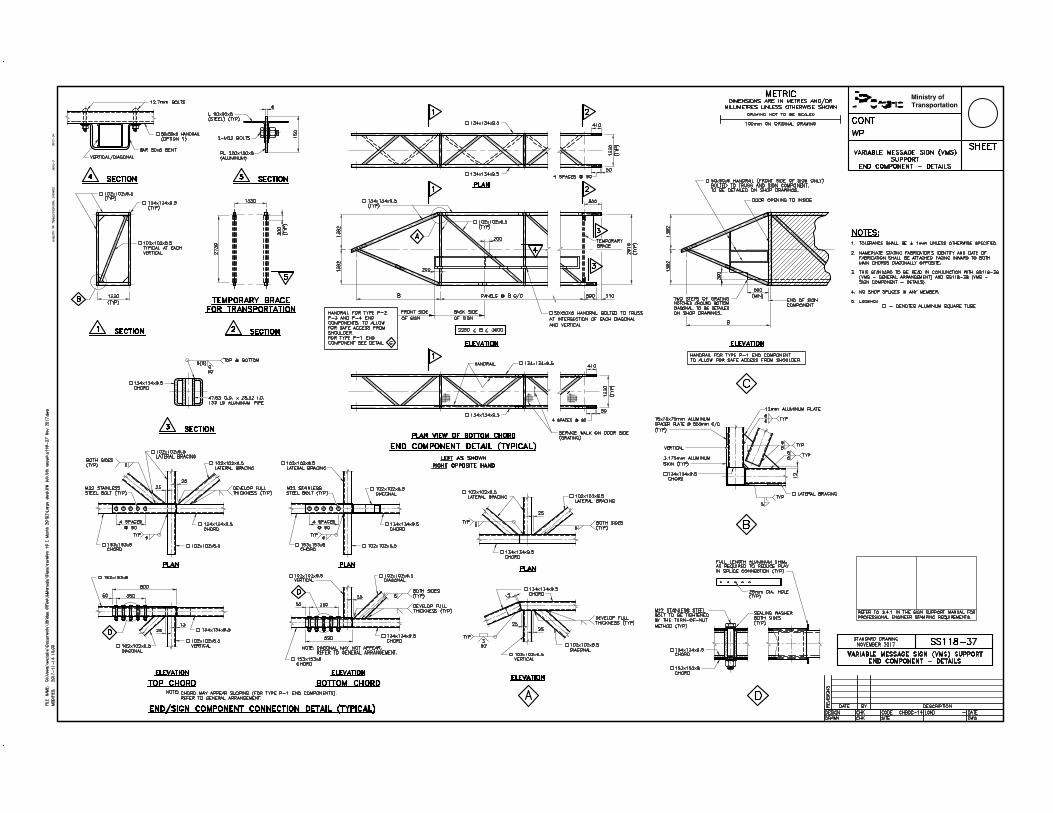


SIGN SUPPORT MANUAL
SECTION 9 – BRIDGE MOUNTED SIGN SUPPORTS
April 2015


SIGN SUPPORT MANUAL
2015 04 01 BRIDGE MOUNTED SIGN SUPPORTS PAGE 9 - 1
9 BRIDGE MOUNTED SIGN SUPPORTS 9.1 GENERAL 9.1.1 STANDARD SIGN SUPPORT
Bridge mounted sign supports are used when it is convenient and economical to mount overhead signs on bridges. For bridges skewed more than 15 degrees, the signs shall be cantilevered from the bridge on a skewed sign support structure to ensure that the sign remains nearly perpendicular to oncoming traffic (Type IV sign support). Generally signboards are kept to within 15 degrees of normal to the direction of oncoming traffic.
9.1.2 DESCRIPTION OF SIGN SUPPORTS
The sign supports main components, the top and bottom chords, the walk arm assembly, the grating and the hinge support pipe are all made of aluminum. To prevent a chemical reaction from occurring between the concrete of the bridge and adjoining aluminum components, neoprene spacers are used. Sign supports are fastened to the bridge using stainless steel anchors.

SIGN SUPPORT MANUAL
2015 04 01 BRIDGE MOUNTED SIGN SUPPORTS PAGE 9 - 2
9.1.3 TYPES OF SIGN SUPPORTS
Four types of bridge mounted sign supports are used: TYPE I – Standard Drawings SS118-12 This type of sign support requires 2 mounting points and is shown in Figure 9.1.3(a). This support type is generally used when a barrier wall is available and when a walkway is not required. The top chord is mounted directly to the barrier wall. The bottom chord is mounted directly to the curb face. A third connection point is located on the deck soffit. Note that this arrangement has a minimal clearance of approximately 330 mm between the sign and the bridge face, therefore resulting in a very difficult installation, often requiring lane closures, traffic detours and special equipment.
FIGURE 9.1.3(a)
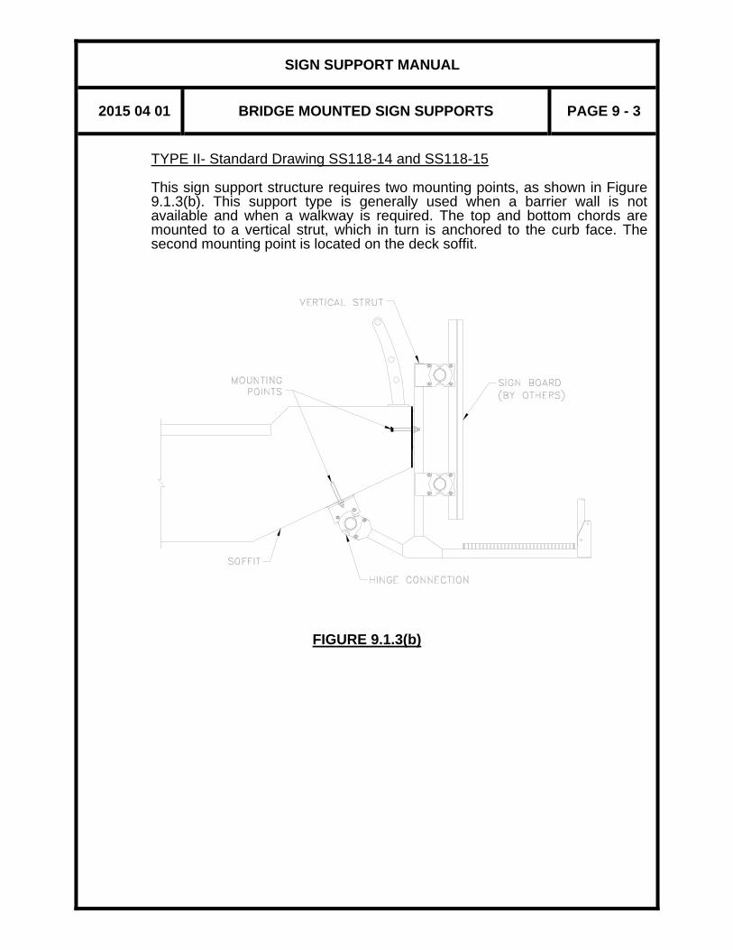
SIGN SUPPORT MANUAL
2015 04 01 BRIDGE MOUNTED SIGN SUPPORTS PAGE 9 - 3
TYPE II- Standard Drawing SS118-14 and SS118-15 This sign support structure requires two mounting points, as shown in Figure 9.1.3(b). This support type is generally used when a barrier wall is not available and when a walkway is required. The top and bottom chords are mounted to a vertical strut, which in turn is anchored to the curb face. The second mounting point is located on the deck soffit.
FIGURE 9.1.3(b)

SIGN SUPPORT MANUAL
2015 04 01 BRIDGE MOUNTED SIGN SUPPORTS PAGE 9 - 4
TYPE III -Standard Drawing SS118-16 and SS118-17 Type III bridge mounted sign support structures require three mounting points, as detailed in Figure 9.1.3(c). This support type is generally used when a barrier wall is available and when a walkway is required. The top and bottom chords are fastened to a vertical strut which in turn is attached to the bridge at two mounting points, on the barrier wall and at the level of the curb face. A third mounting point is located on the deck soffit.
FIGURE 9.1.3(c)

SIGN SUPPORT MANUAL
2015 04 01 BRIDGE MOUNTED SIGN SUPPORTS PAGE 9 - 5
TYPE IV -Standard Drawing SS118-18 and SS118-19 This type of "tapered" support is used when there is a significant skew angle (bridge skew greater than 15°). The approximate distance between the back of the sign board and the face of the bridge deck may vary up to 1800 mm as shown in Figure 9.1.3(d). Walkways form part of the structure. The tapered truss is fastened to a vertical strut at two points, which itself is anchored to the barrier wall, curb face and deck soffit.
FIGURE 9.1.3(d)

SIGN SUPPORT MANUAL
2015 04 01 BRIDGE MOUNTED SIGN SUPPORTS PAGE 9 - 6
9.1.4 CLEARANCE
The clearance provided to bridge mounted sign supports must exceed the clearance to the supporting bridge. The roadway clearance to the small lane designation signs (915 mm wide by 610 mm high) attached to the bottom of sign support structures is 4800 mm.
SIGN SUPPORT MANUAL
2015 04 01 BRIDGE MOUNTED SIGN SUPPORTS PAGE 9 - 7
9.2 PREPARATION OF DRAWINGS 9.2.1 DATA REQUIRED
Before sign supports can be detailed a full cross-section and plan of the bridge is required to show the following data: (i) The station of the bridge. (ii) The bridge clearance. (iii) The bridge drawings. (iv) The skew of the bridge. (v) Direction of traffic; for sign board(s) to be mounted on the bridge (i.e.
North Bound, South Bound, etc.). (vi) Dimension from centre line of sign board(s) to fixed point(s) on the
bridge or highway (e.g. pier, abutment, painted lane markings, etc.). (vii) Dimension of sign board(s).
9.2.2 SUPPORT DRAWINGS
The standard drawings for Types I, II and III sign supports are to be used when the skew of the bridge is less than 15 degrees. Each of these drawings contains one elevation and one detail drawing. The standard drawings for Type IV sign supports are to be used when the skew of bridge exceeds 15 degrees. These drawings consist of one elevation and one detail drawing. An elevation of the structure must be added by the user. The elevation must show the relationships between the bridge, the sign and the roadway. A site plan, typical cross-section and an enlarged front elevation showing all components is normally included, as illustrated in Figure 9.2.2(a). The standard drawings are to be completed in accordance with the following procedure: (i) Add the bridge name and/or the intersection, contract number and W.
P. number in the title block.

SIGN SUPPORT MANUAL
2015 04 01 BRIDGE MOUNTED SIGN SUPPORTS PAGE 9 - 8
(ii) Show on the front elevation, the outline and dimensions of each sign
board. Use broken lines since the signs are not part of the contract. The position of the sign should be dimensioned from the vertical centreline of the sign board to a fixed point, and from the centreline of the lower chord to the bottom of the sign board according to the following table.
SIGN DEPTH (mm)
DIMENSION (mm)
1525 300 1830 350 2130 400 2440 450 2740 500
The dimension between the top of the sign board and the centreline of the upper chord shall be limited to 1100mm. For signs with big depth, the recommended dimension in the table can be increased to suit provided it is not more than 1100mm and the clearance of the bridge mounted sign support(s) still exceed the clearance to the supporting bridge. Indicate the size of each sign and that they are not part of the contract (1830 x 6400 -SIGN BY OTHERS).
(iii) Draw the service walkway on the front elevation. Service walkways; allow maintenance staff access; to luminaries and sign boards; without interference to traffic. The service walkway must extend from the shoulder area (usually the right shoulder) to the remote edge of the sign board. The service walkways are composed of 1524 mm (5 foot) long grating units supported by walk arms. The walk arm is part of the "Service Walk Arm Assembly"; other parts of this assembly include the vertical strut and the brace. This assembly is mounted to the face of the bridge deck, soffit and barrier wall, as detailed in Section 9.1.3. Walkways should be extended by at least 750 mm beyond the ends of the sign board for safety and future considerations.
(iv) The railing should be drawn in the down position on the front elevation.
Railings are available in two lengths, 3050 mm (2 posts BD-221-045-8A) and 3810 mm (3 posts, BD-221-045-10A). The two post railing extends over one 1524 mm (5 foot) grating unit and halfway across each of the two adjacent units (do not use this two post railing to end a walkway). The three post railing extends over two 1524 mm (5 foot) grating units and halfway across the right-hand adjacent unit. The three post railing is used only on the left hand end of a service walkway when the service walkway has an even number of grating units. When an uneven number of grating units are used, either add

SIGN SUPPORT MANUAL
2015 04 01 BRIDGE MOUNTED SIGN SUPPORTS PAGE 9 - 9
one more 1524 mm (5 foot) grating unit or modify a three post unit into a two post end railing.
(v) Draw the vertical centre lines of the sign clamps on the front elevation.
Print along a dimension line above each sign the number, size and spacing. The spacing is normally 1524 mm (5 feet) to coincide with the spacing of the vertical strut clamps which are normally offset by 762 mm (vary to suit individual situation, minimum 250 mm). The following table gives the limits for overhangs, measured from the centre line of the sign clamp to the edge of the sign board.
SIGN SIZE/TYPE MAXIMUM (mm)
MINIMUM (mm)
2740 mm deep 750 150 1524 to 2440 mm
deep 915 150
2740 mm deep, and bevelled end 150 150
1524 to 2440 mm deep, and bevelled
end 450 150
(vi) To assist the user in the completion of these standard drawings,
instructions have been added to the reduced copies included in this Manual. Explanatory notes with arrows indicating the specific area of the drawing to which they apply are provided. These instructions do not appear on the production versions of the standard drawings, and must not appear in the contract.
(vii) Assign a Figure number from the "Part List" on the "Service Walk Arm
Assembly" drawing to all items not already numbered. Show the Figure numbers against the item in an appropriate location with an arrow from the number to the item.

SIGN SUPPORT MANUAL
2015 04 01 BRIDGE MOUNTED SIGN SUPPORTS PAGE 9 - 10
FIGURE 9.2.2(a) GENERAL LAYOUT DRAWING

SIGN SUPPORT MANUAL
2015 04 01 BRIDGE MOUNTED SIGN SUPPORTS PAGE 9 - 11
9.3 PROCESSING 9.3.1 PREPARATION OF ELECTRICAL DRAWINGS
When illumination is required as described in Section 2.5.1, the electrical wiring for the bridge mounted signs is to be supported by the bridge. For new bridges, it is desirable to have the electrical work embedded in concrete. Therefore it is important that the type and location of the sign support be decided upon in time for inclusion of electrical work in the structural design process.

SIGN SUPPORT MANUAL
2015 04 01 BRIDGE MOUNTED SIGN SUPPORTS PAGE 9 - 12
APPENDIX TO SECTION 9
BRIDGE MOUNTED SIGN SUPPORTS
SS118-12 BRIDGE MOUNTED SIGN SUPPORT TYPE I
GENERAL LAYOUT AND DETAILS SS118-14 BRIDGE MOUNTED SIGN SUPPORT TYPE II
GENERAL LAYOUT SS118-15 BRIDGE MOUNTED SIGN SUPPORT TYPE II
SERVICE WALK ARM ASSEMBLY SS118-16 BRIDGE MOUNTED SIGN SUPPORT TYPE III
GENERAL LAYOUT SS118-17 BRIDGE MOUNTED SIGN SUPPORT TYPE III
SERVICE WALK ARM ASSEMBLY SS118-18 BRIDGE MOUNTED SIGN SUPPORT TYPE IV
GENERAL LAYOUT SS118-19 BRIDGE MOUNTED SIGN SUPPORT TYPE IV
SERVICE WALK ARM ASSEMBLY
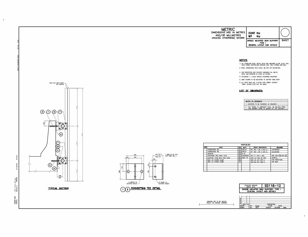

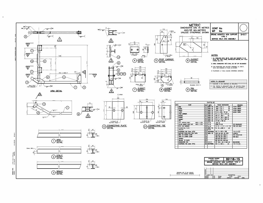


This page is intentionally left blank.

SIGN SUPPORT MANUAL
INDEX
February 2019


SIGN SUPPORT MANUAL
2019 02 15 INDEX PAGE i
Aluminum Alcan Sign Panel, 2-5, 2-6, 3-27, 3-29, 4-20 Appendix, 2-7, 3-32, 4-24, 7-11, 8-17, 9-12 Arrow Board Detail, 4-26 Bolted Joint, 3-14, 3-17, 3-23 Bridge Mounted Sign Support, 1-1, 2-1, 2-3, 9-1 Butterfly Type, 3-1, 3-8, 3-9, 3-12, 3-13, 3-17, 3-25 Cantilever Class Ranges, 3-10 – 3-13 Cantilever Static Sign Support, 1-1, 2-3, 3-1, 3-10 Cantilever Tri-chord, 2-3, 4-2, 4-6, 4-8, 4-10, 4-13, 4-15, 4-20 – 4-22 Centre Mounted, 3-1, 3-2 CHBDC, 2-5, 2-8 – 2-10, 3-1, 3-29, 4-1, 4-20, 4-23, 7-1, 7-10, 8-1, 8-2, 8-15 Clamp, 1-2, 9-9 Clearance, 3-1, 3-4, 3-31, 3-35, 4-1 – 4-3, 4-7, 4-21, 7-5, 7-6, 8-1, 8-2, 8-7, 8-14, 8-15, 9-2, 9-6 – 9-8 Connection Plate, 3-14, 3-18, 3-23 Contours of Frost Depths for Ontario, 2-7 Contract Preparation System, 2-2 CPS Items for Sign Supports, 2-3 Damper, 3-1, 3-3, 3-28 Damper Installation Details, 3-28 Deflections, 3-29, 3-31, 4-7, 4-21, 7-10, 8-7, 8-16 Design Curves, 3-30 Design Dimensions, 3-23, 3-24, 4-14, 4-15, 4-21, 8-8, 8-15 Design Information, 3-29, 4-19, 7-10, 8-15 Distribution of Manual, 1-2, 2-4 Double Cantilever, 3-1 Electrical Drawing, 2-2, 9-11 End Component, 8-3, 8-8 – 8-10, 8-13 Erection, 2-4, 4-10, 8-7 Fatigue, 3-29, 3-30, 4-19 – 4-21, 7-9, 7-10, 8-14, 8-15 Footings, 2-4, 3-3, 3-4, 4-3, 4-7, 4-23, 4-24, 7-5, 7-8, 8-2, 8-7 Foundations, 2-4, 3-31, 4-22, 4-23, 8-16 Frost Depth, 2-5, 2-7, DA 4-1, DA 4-2, DA 4-3, 3-26, 3-31, 4-22, 8-16 Frost Depths for Ontario by Location, 2-7, DA 4-3 Guy Cables, 7-1, 7-4 Inspection, 3-29, 4-19, 7-9, 8-14 Limitations, 2-1, 3-3, 4-3, 4-18, 4-21, 7-2, 8-2, 8-15

SIGN SUPPORT MANUAL
2019 02 15 INDEX PAGE ii
Maintenance, 3-29, 4-19, 7-9, 8-14, 9-8 Metrication, 1-2 Monotube Sign Support, 1-1, 2-1, 2-3, 2-4, 7-1 – 7-11 Numbering System, 1-1 Pole Mounted VMS, 2-3, 8-1, 8-5 – 8-8, 8-11, 8-12, 8-15 – 8-17 Preparation of Drawings, 3-17, 3-22, 3-25, 4-12, 4-14, 4-16, 7-7, 8-10 – 8-11, 9-7 Procedures, 3-9, 4-10, 8-8 Reference Wind Pressure for Ontario, 2-5, 2-7 – 2-10 Scales, 2-2 Sign Board, 2-5, 3-1, 3-3, 3-29, 4-1 – 4-3, 4-7, 7-1, 8-2, 9-5, 9-7 – 9-9 Sign Component, 8-1 – 8-4, 8-7 – 8-13, 8-15 Single Cantilever, 3-1, 3-2, 3-7, 3-9, 3-10, 3-11, 3-14, 3-30 Skew, 9-1, 9-5, 9-7 Soil Conditions, 2-4, 3-1, 3-4, 4-1 – 4-3, 4-7, 7-1, 7-5, 8-1, 8-2, 8-7 Standard Drawings, 1-1, 1-2, 2-1, 3-1, 3-26, 4-7 – 4-10, 4-17, 7-1, 7-5, 7-7, 7-9, 8-5, 8-7, 8-8, 8-13 – 8-15, 8-17, 9-2 – 9-5, 9-7, 9-9 Traffic Protection, 2-4, 3-4, 3-26, 4-7, 4-17, 7-5, 8-7, 8-12 Tri-Chord, 1-1, 2-1, 2-3, 2-4, 4-1, 8-7 Tri-Chord Depth, 4-8 Truss, 2-1, 3-6, 3-23, 3-29, 4-1 – 4-3, 4-8, 8-1, 8-3, 8-8, 8-13, 9-5 Typical Elevation, 3-7, 3-8, 4-3, 4-5, 4-6, 8-3 – 8-6 Typical Layout Plan, 3-3, 3-7, 3-8, 4-3, 4-4, 4-6, 8-3, 8-5, 8-6 Variable Message Sign Support, 1-1, 2-1, 2-3, 8-1—8-17 Variable Message Systems, 2-5 VMS Overhead Truss, 8-1 – 8-4, 8-7, 8-10, 8-12, 8-15 Wind Pressure, 2-5, 2-7 – 2-10, 3-1, 3-26, 4-1, 4-2, 4-10, 4-18, 4-20, 4-23, 7-1, 8-1, 8-2, 8-8 Z-bracket, 3-3, 3-5, 3-6, 3-27, 3-32, 3-34, 4-3, 4-10, 4-19, 4-24, 4-25

Ministry of Transportation Ontario 2019
