siemens power generation - national energy … library/events/2003/seca/sd-vora.pdf · steam...
TRANSCRIPT

S F CS t a t i o n a r y -F u e l C e l l s
April 2003
SECA Program at Siemens WestinghouseS. D. Vora
Siemens Westinghouse Power CorporationApril 15, 2003
April 2003 1©Siemens Westinghouse Power Corporation 2003 All Rights Reserved
S F CS t a t i o n a r y -F u e l C e l l s
SIEMENS
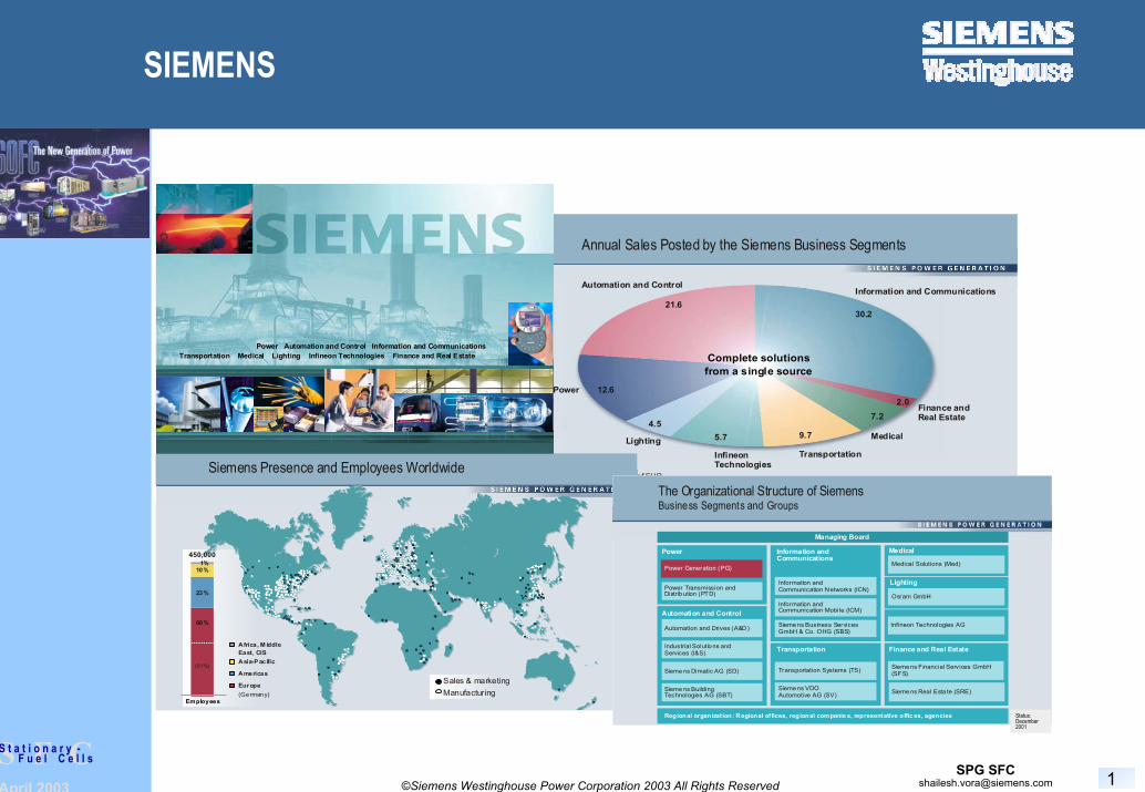
Annual Sales Posted by the Siemens Business Segments
Information and Communications Automation and Control
Medical
Finance andReal Estate
Power 12.6
InfineonTechnologies
LightingTransportation
Complete solutionsfrom a single source
Sales in billions of EUR(FY 1999/2000)
2.07.2
9.75.74.5
21.630.2
Siemens Presence and Employees Worldwide
Sales & marketingManufacturing
450,0001%
10%
23%
66%
(61%)
Africa, M iddle East, CISAsia-P acific
Americas
Europe (Germany)
Employees
PG 2001 1.1e
Transportation Medical Lighting Infineon Technologies Finance and Real EstatePower Automation and Control Information and Communications
Managing Board
Power
Automation and Control
Automation and Drives (A&D )
Industrial Solutio ns and Services (I&S)
Sieme ns Dimatic AG (SD)
Sieme ns BuildingTechnologies AG (SBT)
Regional organization: Regional offices, regional companie s, representative offic es, agencies
Information andCommunication Networks (ICN)
Information andCommunications
Information andCommunication Mobile (ICM)
Sieme ns Business ServicesGmbH & Co. OHG (SBS)
Transportation Systems (TS)
Transportation
Sieme ns VDO Automotive AG (SV)
Osram GmbH
Lighting
Sieme ns F inancial Services GmbH(SFS)
Finance and Real Estate
Medical Solutions (Med)
Medical
Infineon Technologies AG
The Organizational Structure of SiemensBusiness Segments and Groups
Power Generation (PG)
Power Transmission andDistr ib ution (PTD)
Status: January 1, 2001
Sieme ns Real Esta te (SRE)
Status:December 2001
April 2003 2©Siemens Westinghouse Power Corporation 2003 All Rights Reserved
S F CS t a t i o n a r y -F u e l C e l l s
Industrials Solutions and Services (I&S)
Power Transmission and Distribution(PTD)
Siemens FinancingServices (SFS)
Medical Solutions (Med)
Transportation Systems (TS)
Information and Communication Networks (ICN)
Automationand Drives (A&D)
OsramGmbH
Siemens Automotive (AT)
Siemens FinancingServices (SFS)
Siemens Business ServicesGmbH & Co. OHG (SBS)
InfineonTechnologies AG(Siemens subsidiary)
Information and Communications Mobile (ICM)
Siemens Building Technologies AG (SBT)
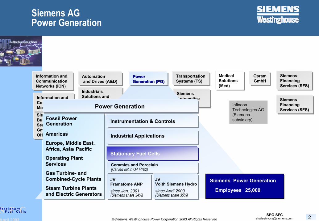
Power Power Generation (PG)Generation (PG)
Siemens Production and Logistics Systems AG (PL) Instrumentation & Controls
JV Framatome ANPsince Jan. 2001(Siemens share 34%)
Industrial Applications
Ceramics and Porcelain(Carved out in Q4 FY02)
Americas
Europe, Middle East, Africa, Asia/ Pacific
Operating PlantServices
Gas Turbine- and Combined-Cycle Plants
Steam Turbine Plantsand Electric Generators
Power GenerationPower Generation
Fossil Power Generation
Employees 25,000
Siemens Power Generation
Siemens AGPower Generation
JV Voith Siemens Hydrosince April 2000(Siemens share 35%)
Stationary Fuel Cells

April 2003 3©Siemens Westinghouse Power Corporation 2003 All Rights Reserved
S F CS t a t i o n a r y -F u e l C e l l s
Stationary Fuel Cells
150 Employees
Chartered to Commercialize SOFC Power Systems for the Distributed Generation Market
Focused on Seal-less, Cathode Supported TubularSOFC Design
YSZ Electrolyte, 1000 ºC Operating Temperature
Expertise inHigh Temperature MaterialsCeramic Processing, Ceramic Powder, Cell and Module ManufacturingElectrochemistry and Cell testingHydrocarbon ReformationBOP AssemblySystems Testing

April 2003 4©Siemens Westinghouse Power Corporation 2003 All Rights Reserved
S F CS t a t i o n a r y -F u e l C e l l s
Stationary Fuel Cells - Accomplishments
Developed State-of the art, 150 cm Active Length (834 cm2
active area), Cathode Supported Tubular SOFCs
Demonstrated Lifetime of >60,000 Operating Hours with Voltage Degradation Rates < 0.1% per 1000 Hours and Thermal Cycle Capability of >100 Cycles
Developed Internal Reformation Technology
Designed, Manufactured and Tested Complete Atmospheric and Pressurized Hybrid SOFC Power Systems

April 2003 5©Siemens Westinghouse Power Corporation 2003 All Rights Reserved
S F CS t a t i o n a r y -F u e l C e l l s
SOFC Power System Demonstrations with Tubular SOFCs
100 kWe Atmospheric Combined Heat and Power (CHP) System
20,000+ hours with no measurable voltage degradation46% electrical efficiencyGrid and District Heating Connected
200 kWe Pressurized Hybrid (PH) System
3000+ hours 52% electrical efficiency
200 kWe Pressurized Hybrid (PH) System
3000+ hours 52% electrical efficiency

April 2003 6©Siemens Westinghouse Power Corporation 2003 All Rights Reserved
S F CS t a t i o n a r y -F u e l C e l l s
Highest Priority for Commercialization
Lower Product Cost ($/kWe)
Cost
Power Density

April 2003 7©Siemens Westinghouse Power Corporation 2003 All Rights Reserved
S F CS t a t i o n a r y -F u e l C e l l s
SECA Program Objectives
Develop SOFC System Prototypes with a net Power Output of 5-10 kWe for Stationary and Transportation Applications with a Cost Target of < $ 400/kWe.
April 2003 8©Siemens Westinghouse Power Corporation 2003 All Rights Reserved
S F CS t a t i o n a r y -F u e l C e l l s
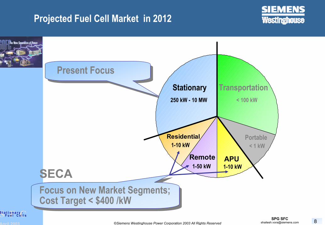
Projected Fuel Cell Market in 2012
Present Focus
Residential
Remote APU
TransportationStationary250 kW - 10 MW < 100 kW
1-10 kW
1-50 kW 1-10 kW
< 1 kW
SECAFocus on New Market Segments;Cost Target < $400 /kW
Portable
April 2003 9©Siemens Westinghouse Power Corporation 2003 All Rights Reserved
S F CS t a t i o n a r y -F u e l C e l l s
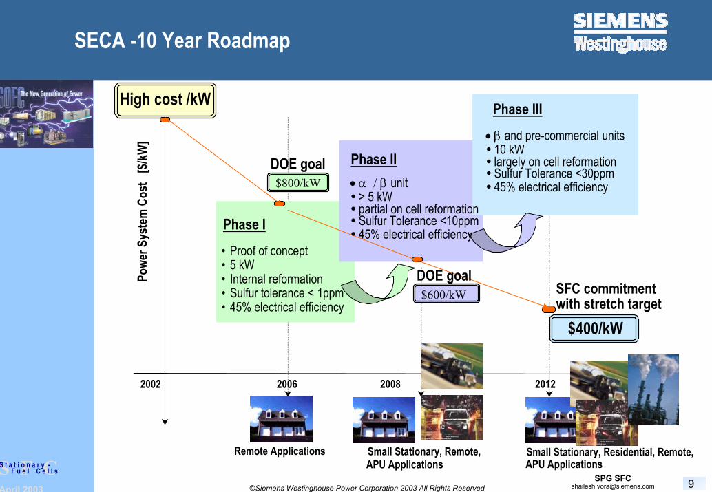
SECA -10 Year Roadmap
Phase I
Powe
r Sys
tem
Cos
t [$
/kW]
High cost /kW
$800/kW
$600/kW
$400/kW
Remote Applications Small Stationary, Remote,APU Applications
Small Stationary, Residential, Remote,APU Applications
2002 2006
DOE goal
• Proof of concept• 5 kW • Internal reformation• Sulfur tolerance < 1ppm• 45% electrical efficiency
Phase II• α / β unit
> 5 kW partial on cell reformationSulfur Tolerance <10ppm45% electrical efficiency
Phase III• β and pre-commercial units
10 kW largely on cell reformationSulfur Tolerance <30ppm45% electrical efficiency
DOE goal
2008
SFC commitmentwith stretch target
2012

April 2003 10©Siemens Westinghouse Power Corporation 2003 All Rights Reserved
S F CS t a t i o n a r y -F u e l C e l l s
Siemens Westinghouse SECA Team
Siemens Westinghouse
Fuel Cell Technologies
Blasch Precision Ceramics
Zircar Refractory Ceramics
Remote/ResidentialFuel Cell Technologies
Lennox
Trane
Dominion
TransportationFord
Eaton
MilitaryNewport News
Eaton
Customer / Market TeamTechnology Team
Key Team Members provide Market Access and Industry Specific ExpertiseTo broaden Market Opportunities and New Applications
April 2003 11©Siemens Westinghouse Power Corporation 2003 All Rights Reserved
S F CS t a t i o n a r y -F u e l C e l l s
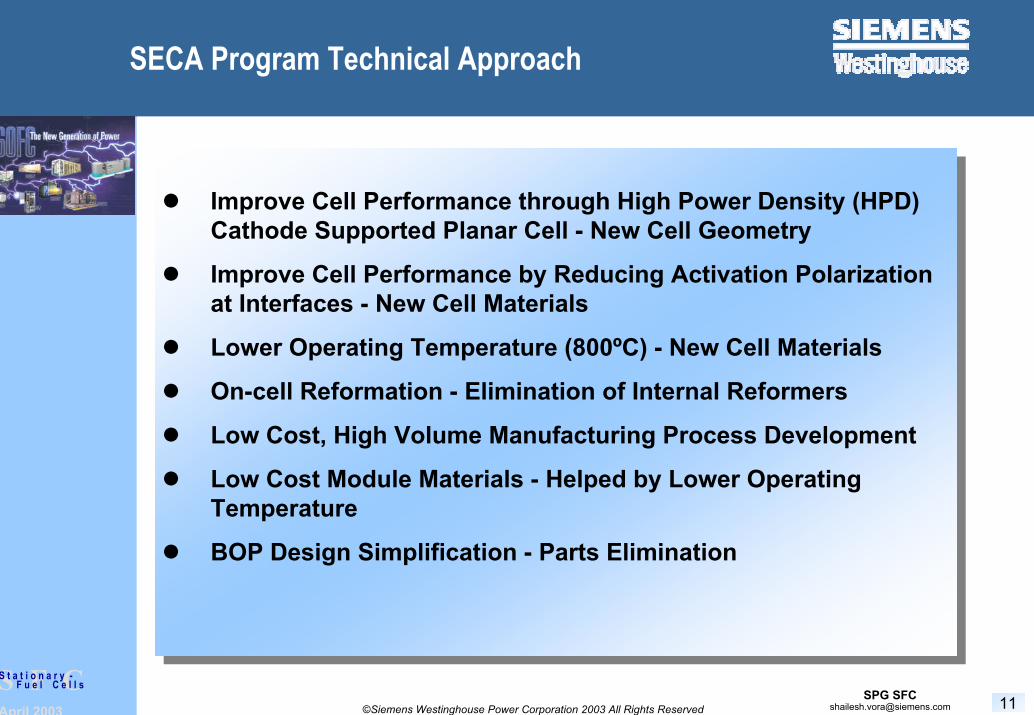
SECA Program Technical Approach
Improve Cell Performance through High Power Density (HPD) Cathode Supported Planar Cell - New Cell Geometry
Improve Cell Performance by Reducing Activation Polarization at Interfaces - New Cell Materials
Lower Operating Temperature (800ºC) - New Cell Materials
On-cell Reformation - Elimination of Internal Reformers
Low Cost, High Volume Manufacturing Process Development
Low Cost Module Materials - Helped by Lower Operating Temperature
BOP Design Simplification - Parts Elimination
April 2003 12©Siemens Westinghouse Power Corporation 2003 All Rights Reserved
S F CS t a t i o n a r y -F u e l C e l l s
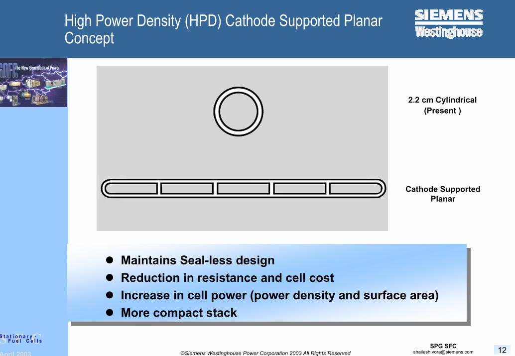
High Power Density (HPD) Cathode Supported Planar Concept
Maintains Seal-less design Reduction in resistance and cell cost Increase in cell power (power density and surface area)More compact stack
2.2 cm Cylindrical(Present )
Cathode Supported Planar

April 2003 13©Siemens Westinghouse Power Corporation 2003 All Rights Reserved
S F CS t a t i o n a r y -F u e l C e l l s
Development of HPD Cell Design
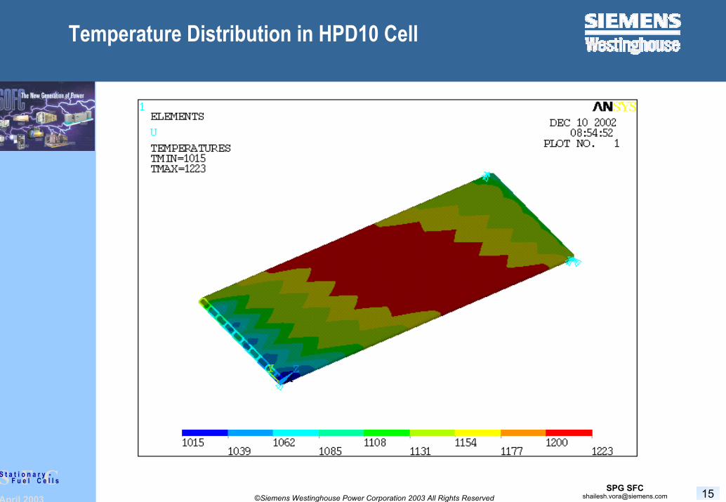
Computational Thermal Model of HPD Cell Developed to Optimize Cell Design and Dimensions
Theoretical Performance Estimated by Electrochemical modeling

April 2003 14©Siemens Westinghouse Power Corporation 2003 All Rights Reserved
S F CS t a t i o n a r y -F u e l C e l l s
Evolution of Cell Design
Standard Cylindrical
HPD5R0-2002
HPD5R1-2003
HPD10 >2003
April 2003 15©Siemens Westinghouse Power Corporation 2003 All Rights Reserved
S F CS t a t i o n a r y -F u e l C e l l s
Temperature Distribution in HPD10 Cell

April 2003 16©Siemens Westinghouse Power Corporation 2003 All Rights Reserved
S F CS t a t i o n a r y -F u e l C e l l s
Extrusion of HPD Tube
April 2003 17©Siemens Westinghouse Power Corporation 2003 All Rights Reserved
S F CS t a t i o n a r y -F u e l C e l l s
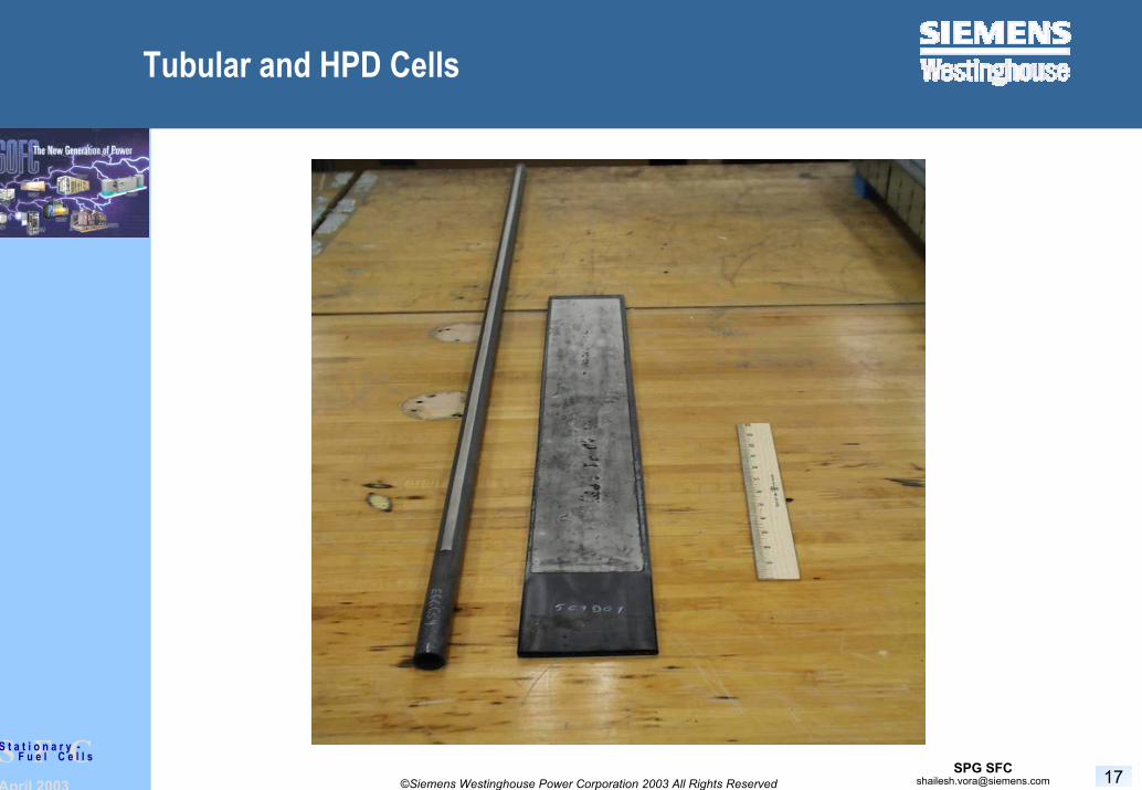
Tubular and HPD Cells

April 2003 18©Siemens Westinghouse Power Corporation 2003 All Rights Reserved
S F CS t a t i o n a r y -F u e l C e l l s
Performance Comparison - Tubular Vs. HPD5
Cell Performance Comparison at 1000oC Cylindrical and HPD Cells
0.40
0.45
0.50
0.55
0.60
0.65
0.70
0.75
0.80
0.85
50 100 150 200 250 300 350 400 450 500 550 600 650Current Density (mA/cm 2 )
Volta
ge (
V)
0.000
0.050
0.100
0.150
0.200
0.250
0.300
0.350
0.400
Pow
er D
ensi
ty (W
/cm
2 )
Test 779, 85% FU and 25% AU (HPD5)Test 558, 85% FU and 25% AU(Cylindrical)

April 2003 19©Siemens Westinghouse Power Corporation 2003 All Rights Reserved
S F CS t a t i o n a r y -F u e l C e l l s
Cell Power Enhancement
Developed Mixed Ionic and Electronic Conducting Composite Interlayer
Lowered Activation Polarization at the Cathode-Electrolyte Interface - Enhanced Cell Performance at Lower Temperatures

April 2003 20©Siemens Westinghouse Power Corporation 2003 All Rights Reserved
S F CS t a t i o n a r y -F u e l C e l l s
Performance Comparison - Std. Interlayer Vs. Composite Interlayer (Tubular Cells)
0.400
0.450
0.500
0.5500.600
0.650
0.700
0.750
0.800
0 100 200 300 400
J, mA/cm2
Cel
l Vol
tage
, Vinterlayered regular
900oCair vs 89%H2+11%H2O83% fuel utilization

April 2003 21©Siemens Westinghouse Power Corporation 2003 All Rights Reserved
S F CS t a t i o n a r y -F u e l C e l l s
Performance Comparison - Tubular Vs. HPD
Performance DataCylindrical versus HPD5
and SECA Targets
0.40
0.45
0.50
0.55
0.60
0.65
0.70
0.75
0.80
0.85
50 100 150 200 250 300 350 400 450 500 550 600 650Current Density (mA/cm^2)
Volta
ge (
V)
0.000
0.050
0.100
0.150
0.200
0.250
0.300
0.350
0.400
Pow
er D
ensi
ty (W
/cm
^2)
Blue Test 779 HPD5Red Test 558 Cyl.
M onth 6
M onth 36
M onth 25
April 2003 22©Siemens Westinghouse Power Corporation 2003 All Rights Reserved
S F CS t a t i o n a r y -F u e l C e l l s
Cell Development - Summary
Reduction in Ohmic Resistance through HPD Design
Reduction in Activation Polarization through Composite Interlayer
Target Power Increase for HPD Cells Compared with Tubular Cells - 2X at Half the Length
Improves Packing Density

April 2003 23©Siemens Westinghouse Power Corporation 2003 All Rights Reserved
S F CS t a t i o n a r y -F u e l C e l l s
Low Temperature Electrolyte
Selected LSGM (Mg and Sr doped lanthanum gallate) for Evaluation
April 2003 24©Siemens Westinghouse Power Corporation 2003 All Rights Reserved
S F CS t a t i o n a r y -F u e l C e l l s
LSGM As Low Temperature Electrolyte
High Electrolyte Oxygen-ion Conductivity: σ(LSGM@800oC)= σ(YSZ@1000oC)
Excellent Chemical and Structural Compatibility with PerovskiteCathode Substrate
Higher Cell Performance over a Wider Temperature Range
Potential Cost Reduction due to Lower Operating Temperature

April 2003 25©Siemens Westinghouse Power Corporation 2003 All Rights Reserved
S F CS t a t i o n a r y -F u e l C e l l s
Characterization of Properties of LSGM and Compatible Materials
Electrical Conductivity
Thermal Expansion Coefficient
Dimensional Stability
Chemical Reactivity of LSGM with Cathode Substrate at Operating Temperature
Electrochemical
Feasibility of Plasma Spraying LSGM Film on Cathode Substrate

April 2003 26©Siemens Westinghouse Power Corporation 2003 All Rights Reserved
S F CS t a t i o n a r y -F u e l C e l l s
Selection of LSGM and Compatible Materials
Electrolyte: LSGM
Cathode: Doped Lanthanum Manganite
Interconnection: Doped Lanthanum Chromite
Cathode Interlayer: Mixed Ionic and Electronic Conductor
Anode Interlayer and Anode: TBD
Over 10 compositions of Cathode and Interconnectionwere selected for Screening
April 2003 27©Siemens Westinghouse Power Corporation 2003 All Rights Reserved
S F CS t a t i o n a r y -F u e l C e l l s
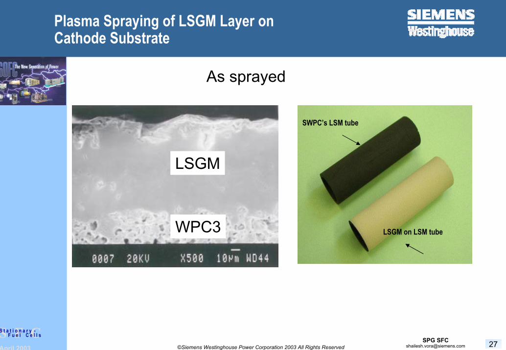
Plasma Spraying of LSGM Layer on Cathode Substrate
LSM Tube
LSGM Coating
LSGM on LSM tube
SWPC’s LSM tube
As sprayed
LSGM
WPC3

April 2003 28©Siemens Westinghouse Power Corporation 2003 All Rights Reserved
S F CS t a t i o n a r y -F u e l C e l l s
Low Temperature Electrolyte - Summary
Selected Electrolyte and Cathode Compositions
Prepared Powders for Cell Preparation and Electrochemical Characterization
Initiated Feasibility Study of Plasma Spraying LSGM on Cathode

April 2003 29©Siemens Westinghouse Power Corporation 2003 All Rights Reserved
S F CS t a t i o n a r y -F u e l C e l l s
Low Cost High Volume Manufacturing
Initiated Feasibility study of All Sintered Cell
Higher Material Utilization
Reduced Manufacturing Steps
Higher Throughput
Initiated Feasibility Study of Low Pressure Plasma Spraying (LPPS)
Higher Material Utilization
Lower Densification Temperature
Higher Throughput

April 2003 30©Siemens Westinghouse Power Corporation 2003 All Rights Reserved
S F CS t a t i o n a r y -F u e l C e l l s
Low Cost Module Materials (With Blasch)
Initiated Development of Low Gas Permeable Ceramic Stack Housing
Initiated Feasibility Study of Lower Purity Insulation (Possible Due to Lower Operating Temperature)

April 2003 31©Siemens Westinghouse Power Corporation 2003 All Rights Reserved
S F CS t a t i o n a r y -F u e l C e l l s
Generator Design and BOP Simplification (With FCT)
Model Showing FCT Alpha Prototype

April 2003 32©Siemens Westinghouse Power Corporation 2003 All Rights Reserved
S F CS t a t i o n a r y -F u e l C e l l s
Generator Design and BOP Simplification (With FCT)
FCT Recirculator Design in Testing

April 2003 33©Siemens Westinghouse Power Corporation 2003 All Rights Reserved
S F CS t a t i o n a r y -F u e l C e l l s
Generator Design and BOP Simplification (With FCT)
Prototype Combustor and Flame Holder Designs

April 2003 34©Siemens Westinghouse Power Corporation 2003 All Rights Reserved
S F CS t a t i o n a r y -F u e l C e l l s
Generator Design and BOP Simplification (With FCT)
Summary
Incorporating Lessons Learned from Alpha Demonstration Units.
Beta Unit with Full Length (834 cm2 active area) Tubular Cells Being Designed with an Objective to Maintain Commonality Between Beta and SECA Units.
Design of SECA Unit with HPD Cells Initiated.

April 2003 35©Siemens Westinghouse Power Corporation 2003 All Rights Reserved
S F CS t a t i o n a r y -F u e l C e l l s
SECA Program Summary
Contract for First 2 years Signed in September 2002
HPD5 Selected as Baseline Design for Development and Test
HPD10 Undergoing Evaluation
LSGM vs. YSZ Evaluation Initiated
LPPS, Thin-film Sintering Processes being Evaluated as Alternative to Atmospheric Plasma Spraying
Low Cost Module Materials Being Investigated
Generator Design and BOP Simplification Initiated

April 2003 36©Siemens Westinghouse Power Corporation 2003 All Rights Reserved
S F CS t a t i o n a r y -F u e l C e l l s
Future Work
Continue Development of Cell Design and Cell Fabrication
Make a Decision on LSGM Vs. YSZ for POC Unit
Develop Generator Design for POC unit

April 2003 37©Siemens Westinghouse Power Corporation 2003 All Rights Reserved
S F CS t a t i o n a r y -F u e l C e l l s
Stationary Fuel Cells
Siemens Westinghouse Stationary Fuel Cells converted from R&D department to a business unit with a pilot manufacturing facilityFirst environmental friendly commercial product CHP 250
37
New Commercial factory (Milestones):1-Site Selection/Groundbreaking2-Finalized Manufacturing Building3-Implemented Manufacturing Equipment4-Qualified Production Processes5-Start Commercial Shipments
(no SOx; no CO; NOx < 1ppm)

April 2003 38©Siemens Westinghouse Power Corporation 2003 All Rights Reserved
S F CS t a t i o n a r y -F u e l C e l l s
Stationary Fuel Cells - Manufacturing Facility
Munhall, Pennsylvania Location…180,000 sq. ft. - Phase I Building