siemens plm software integrated automotive circuit board ... · siemens plm software 4. circuit...
TRANSCRIPT
Siemens PLM Software
www.siemens.com/simcenter
Integrated automotive circuit board design and verification Digitalizing development of safety-critical ADAS, AV and EV electronics systems
The market for automotive printed circuit boards (PCBs) will surge with the widespread adoption of advanced driver assistance (ADAS) and autono-mous vehicle (AV) systems. As self-driving vehicles become a reality on the highways, durability and reliability will become crucial to the success of safety-critical PCB applications. Regulations requiring ever-increasing safety standards are forcing companies who design and manufacture PCBs to adopt fast, efficient, sophisticated, right-first-time development prac-tices. PCB suppliers can turn these challenges into opportunities with a fully digitalized, simulation-driven development process.
Greg Roth Director of Automotive and Transportation Solutions Siemens PLM Software
White paper | Integrated automotive circuit board design and verification
2Siemens PLM Software
Developing safety-critical ADAS, AV and EV electronics systems
The ADAS and AV revolutionThe use of PCBs in vehicles is already remarkable – sys-tems and operations that currently use them include lighting, transmission controls, comfort controls, engine and emissions management, infotainment systems, power relay timing, radar, GPS, ADAS and much more. Traditionally, most automotive electronic systems cir-cuit boards had marginal functional and reliability requirements. If an instrument panel or radio circuit board failed, it would require an inconvenient visit to the dealer for service. Failure of more safety-critical electronics − for engine or transmission controls, igni-tion, antilock braking, or transmission controls − results in an inoperable vehicle.
The stakes are enormously higher with the emergence of ADAS and AV technologies. Reliability of the electron-ics systems and their hardware/circuit boards is quickly becoming a paramount, urgent focus in the industry. An electrolytic capacitor that overheats or a surface mount
component solder joint that fatigues and cracks due to thermal or vibration stress, for example, can result in potentially catastrophic system failure.
Suppliers of PCBs are already expected to deliver boards with materials that can withstand harsh use and long lifecycles. The industry demands durable, high-tempera-ture PCBs that can dissipate heat quickly, but with the revolution of ADAS and AV systems, automotive applica-tions of PCBs will explode. Electronics and software will drive the evolution as sophisticated processors, sensors, radar, LIDAR, cameras and software systems become crucial in ensuring precise car dynamics.
Focus on safetySafety is the primary requirement for self-driving vehi-cles, and the only requirement that matters. As safety and reliability remain in the forefront, so does the need to account for all aspects of electronic systems – includ-ing operational environments, power duty cycles, com-ponent tolerances, assembly and manufacturing vari-ances, and others.
For the industry to make self-driving cars a reality, PCB suppliers must develop durable, robust and reliable systems, and convince a skeptical public and regulators that electronic systems will work 100 percent of the time. Traditionally, this proof was provided through physical testing in thermal chambers and vibration cells. Failures in testing required a redesign or new compo-nents resulting in cost overruns and missed deadlines.
The traditional approach is no longer sufficient to dem-onstrate that a circuit board design will meet safety-critical requirements. Currently, companies want proof early in the development process to verify that designs are safe and robust. The answer is simulation.
White paper | Integrated automotive circuit board design and verification
3Siemens PLM Software
Simulating all aspects of performanceSimulation today is typically limited to circuit simulation for functionality, circuit board trace layout and usually a basic level of thermal analysis. Current simulation pro-cesses are disjointed, disconnected and inflexible. The limitations are further exacerbated by the fact that different engineering domains – electrical and mechani-cal − are involved. Changes in one domain often are not accounted for or evaluated in the other. An electronic component change that results in higher power dissipa-tion can trigger a thermal overload if not evaluated.
An integrated, end-to-end development processTo prove that the reliability, robustness and roadworthi-ness of AV systems meet safety standards, PCB suppliers must adopt an integrated, multi-domain, simulation-driven development process that evaluates all aspects of circuit board performance, including:
• Circuit performance – with advanced circuit design and analysis, engineers can verify that the target functionality, reliability and robustness are achieved in concept.
• Layout optimization – optimizes board reliability by evaluating component placement, trace routing, the number of layers, manufacturing rules, electromag-netic compatibility and electromagnetic interference.
• 3D CAD modeling – a complete CAD model of the circuit board is required to evaluate mechanical physics through simulation of flow, thermal and vibra-tion behavior, a crucial safeguard for safety-critical systems. A 3D PCB model is also required to assess mechanical packaging and assembly concerns for manufacturing.
• Thermal analysis – provides insights that help engi-neers optimize heat conduction and transfer, thermal and electrical conductivity, airflow and other factors that can compromise the integrity of safety-critical designs.
• Structural analysis – simulates, in detail, the structural physics behavior of the board to evaluate thermal and vibrational stresses that are the primary causes of failure.
• Fatigue analysis – virtually validates that circuit boards are optimized for durability and fatigue performance.
• Performance optimization – helps identify the best design alternatives to temperature, mass, cost and other factors.
White paper | Integrated automotive circuit board design and verification
4Siemens PLM Software
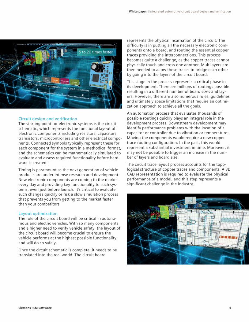
Circuit design and verificationThe starting point for electronic systems is the circuit schematic, which represents the functional layout of electronic components including resistors, capacitors, transistors, microcontrollers and other electrical compo-nents. Connected symbols typically represent these for each component for the system in a methodical format, and the schematics can be mathematically simulated to evaluate and assess required functionality before hard-ware is created.
Timing is paramount as the next generation of vehicle products are under intense research and development. New electronic components are coming to the market every day and providing key functionality to such sys-tems, even just before launch. It’s critical to evaluate such changes quickly or risk a slow simulation process that prevents you from getting to the market faster than your competitors.
Layout optimizationThe role of the circuit board will be critical in autono-mous and electric vehicles. With so many components and a higher need to verify vehicle safety, the layout of the circuit board will become crucial to ensure the vehicle performs at the highest possible functionality, and will do so safely.
Once the circuit schematic is complete, it needs to be translated into the real world. The circuit board
represents the physical incarnation of the circuit. The difficulty is in putting all the necessary electronic com-ponents onto a board, and routing the essential copper traces providing the interconnections. This process becomes quite a challenge, as the copper traces cannot physically touch and cross one another. Multilayers are then needed to allow these traces to bridge each other by going into the layers of the circuit board.
This stage in the process represents a critical phase in its development. There are millions of routings possible resulting in a different number of board sizes and lay-ers. However, there are also numerous rules, guidelines and ultimately space limitations that require an optimi-zation approach to achieve all the goals.
An automation process that evaluates thousands of possible routings quickly plays an integral role in the development process. Downstream development may identify performance problems with the location of a capacitor or controller due to vibration or temperature. Moving the components would require a new copper trace routing configuration. In the past, this would represent a substantial investment in time. Moreover, it may not be possible to trigger an increase in the num-ber of layers and board size.
The circuit trace layout process accounts for the topo-logical structure of copper traces and components. A 3D CAD representation is required to evaluate the physical performance of a model, and this step represents a significant challenge in the industry.
White paper | Integrated automotive circuit board design and verification
5Siemens PLM Software
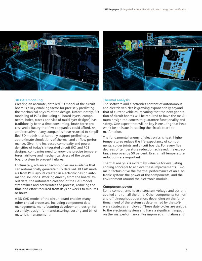
3D CAD modelingCreating an accurate, detailed 3D model of the circuit board is a key enabling factor for precisely predicting the mechanical physics of the design. Unfortunately, 3D modeling of PCBs (including all board layers, compo-nents, holes, traces and vias of multilayer designs) has traditionally been a time-consuming, brute-force pro-cess and a luxury that few companies could afford. As an alternative, many companies have resorted to simpli-fied 3D models that can only support preliminary, approximate simulations of thermal and airflow perfor-mance. Given the increased complexity and power densities of today’s integrated circuit (IC) and PCB designs, companies need to know the precise tempera-tures, airflows and mechanical stress of the circuit board system to prevent failures.
Fortunately, advanced technologies are available that can automatically generate fully detailed 3D CAD mod-els from PCB layouts created in electronic design auto-mation solutions. Working directly from the board lay-out data, the automated creation of the CAD model streamlines and accelerates the process, reducing the time and effort required from days or weeks to minutes or hours.
A 3D CAD model of the circuit board enables many other critical processes, including component data management, manufacturing development, design for assembly, design for manufacturing, costing and bill of materials management.
Thermal analysisThe software and electronics content of autonomous and electric vehicles is growing exponentially beyond that of current vehicles, meaning that the next genera-tion of circuit boards will be required to have the maxi-mum design robustness to guarantee functionality and safety. One aspect that will be key is ensuring that heat won’t be an issue in causing the circuit board to malfunction.
The fundamental enemy of electronics is heat; higher temperatures reduce the life expectancy of compo-nents, solder joints and circuit boards. For every five degrees of temperature reduction achieved, life expec-tancy improves by 50 percent. Even small temperature reductions are important.
Thermal analysis is extremely valuable for evaluating cooling concepts to achieve these improvements. Two main factors drive the thermal performance of an elec-tronic system: the power of the components, and the environment around the electronic module.
Component powerSome components have a constant voltage and current applied and run all the time. Other components turn on and off throughout operation, depending on the func-tional need of the system as determined by the soft-ware strategies employed. These duty cycles are unique to the electronic system and have a significant impact on thermal performance. For improved simulation and
White paper | Integrated automotive circuit board design and verification
6Siemens PLM Software
prediction of performance, these duty cycles should be evaluated as a transient time-based response. Some components have different technologies and packaging configurations that respond better or worse to the applied voltages and currents.
New technologies can force many system modifications. Software is often considered the easy way to address functional shortcomings of a system. While it may be easy to change lines of code, the resulting conse-quences on operational temperatures can be cata-strophic. Apparently benign software modifications can trigger many problems. Changing duty cycle from 50 to 70 percent may be simple to encode, but the resulting temperature impacts on the metal-oxide-semiconductor field-effect transistor (MOSFET) can exceed die temper-ature ratings, resulting in early failure.
The electronic module environmentIn the latter part of the 20th century, most automotive electronics were placed in relatively stable thermal environments like the dashboard. However, as packag-ing space, wire harness length and location became more critical, electronic systems were often placed in more inhospitable locations. In one instance, an elec-tronic module was placed near the exhaust manifold.
For newer ADAS and autonomous vehicle technologies, it may not be so obvious when a location is problematic. For example, ADAS cameras are mounted at the rear-view mirror, high up in the windshield area.
However, the use-case scenarios need to be thought out. On cold mornings, for example, the windshield defroster generates a blast of hot air that blows directly on the camera module. Quick thermal changes are trouble for such systems. Likewise, desert locations can wreak havoc due to solar thermal radiation, causing high temperatures on ADAS cameras. The first thing a driver will do upon entering the car is turn on the air conditioning, blasting cool air onto the camera.
Until recently, such temperature conditions were miti-gated by putting electronics in thermal-friendly loca-tions in the car. However, as development moves for-ward, the electronics have to be more robust and reliable to survive the new environments demanded by advancing vehicle technologies.
Structural analysisConducting stress analysis of electronic systems is not a new concept, but until recently, it has not been practi-cal. In any electronic system that’s functioning and
heating up, temperature changes and vibration intro-duce stresses. Let’s take each one separately.
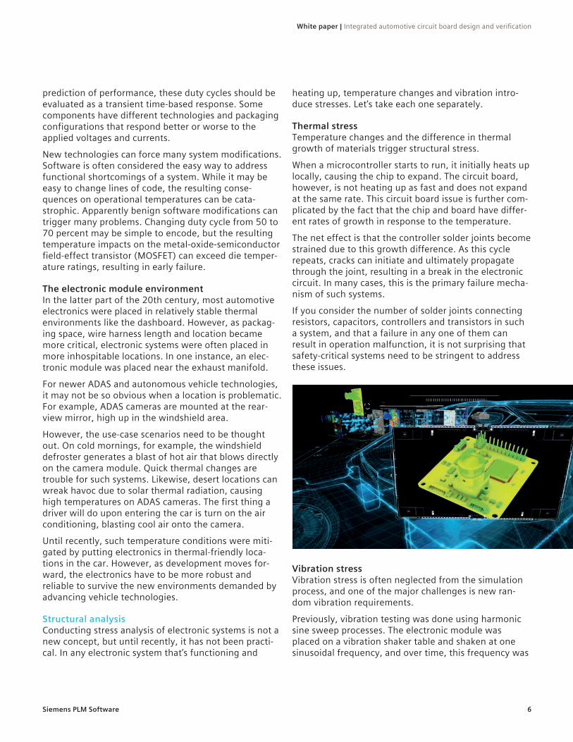
Thermal stress Temperature changes and the difference in thermal growth of materials trigger structural stress.
When a microcontroller starts to run, it initially heats up locally, causing the chip to expand. The circuit board, however, is not heating up as fast and does not expand at the same rate. This circuit board issue is further com-plicated by the fact that the chip and board have differ-ent rates of growth in response to the temperature.
The net effect is that the controller solder joints become strained due to this growth difference. As this cycle repeats, cracks can initiate and ultimately propagate through the joint, resulting in a break in the electronic circuit. In many cases, this is the primary failure mecha-nism of such systems.
If you consider the number of solder joints connecting resistors, capacitors, controllers and transistors in such a system, and that a failure in any one of them can result in operation malfunction, it is not surprising that safety-critical systems need to be stringent to address these issues.
Vibration stress Vibration stress is often neglected from the simulation process, and one of the major challenges is new ran-dom vibration requirements.
Previously, vibration testing was done using harmonic sine sweep processes. The electronic module was placed on a vibration shaker table and shaken at one sinusoidal frequency, and over time, this frequency was

White paper | Integrated automotive circuit board design and verification
7Siemens PLM Software
changed to higher or lower levels. Evaluating this using stress fatigue simulation is fairly straightforward.
However, real-life vibration is represented by multiple frequencies acting at the same time in a more random pattern. While testing protocols have been developed to reproduce such scenarios, vibration stress simulation that can be used in fatigue assessment still lags behind. The industry is making headway and improvements in this area, though: new simulation technologies designed to evaluate stress response to random vibra-tion and related cycle counting techniques for fatigue and durability assessment are now available in simula-tion codes.
Traditionally, circuit boards were overdesigned to meet durability and robustness targets, resulting in higher costs, mass and time to market. Alternatively, circuit boards were designed to be expendable to compensate for what could not be simulated in real life. However, this is no longer an option. Companies need to achieve optimal performance and the lowest costs. Ultimately, thermal and vibration stress simulations should be performed together, as this represents real life.
Fatigue analysisThe results of structural simulations must be applied in fatigue and durability studies that can help understand overall durability and robustness over time. Assuming that the solder joint stress does not surpass ultimate strength and fail on the first power up and vibration, it will take time for the cracks to form and propagate.
Companies ensure safety and robustness over the fore-casted life of an electronic system by thoroughly evalu-ating the stresses. Are the stress levels below the endur-ance limit of the materials? If the answer is yes, then there is high probability it will function for the lifetime of the system. If the stress is above the endurance limit, it then is a matter of time until the crack occurs; if so, how long will it take to fail? Given enough time, most everything will degrade. However, if a crack takes 100 years to fail, that can be considered acceptable. This assessment and risk analysis process is performed in all engineering industries.
Many electronic system components and materials have not been investigated to this level of detail. Fatigue assessments don’t exist to quantify life expectancy and are further complicated by the solder being reformu-lated to remove or reduce levels of lead due to regula-tory pressures and requirements. Material fatigue char-acterization often lags in such situations and inhibits accurate forecasts of life expectancy. This is a typical issue in the industry, as fatigue testing of new materials takes time and incurs considerable costs.
In response, the industry has leveraged general risk factor assessments and empirical knowledge to guide development. While they are useful, these often result in overdesigned products to achieve design and safety margins. As the simulation capabilities for electronic systems improve as required by the next generation of vehicle development, the industry will demand these new material properties.
View the automotive circuit board development videohttp://bit.ly/2IQeCSq
Siemens PLM Software
HeadquartersGranite Park One 5800 Granite Parkway Suite 600 Plano, TX 75024 USA +1 972 987 3000
AmericasGranite Park One 5800 Granite Parkway Suite 600 Plano, TX 75024 USA +1 314 264 8499
EuropeStephenson House Sir William Siemens Square Frimley, Camberley Surrey, GU16 8QD +44 (0) 1276 413200
Asia-PacificUnit 901-902, 9/FTower B,Manulife Financial Centre223-231 Wai Yip Street,Kwun Tong, KowloonHong Kong +852 2230 3333
www.siemens.com/plm© 2019 Siemens Product Lifecycle Management Software Inc. Siemens and the Siemens logo are registered trademarks of Siemens AG. Femap, HEEDS, Simcenter 3D and Teamcenter are trademarks or registered trademarks of Siemens Product Lifecycle Management Software Inc. or its subsidiaries in the United States and in other countries. Simcenter, Simcenter Amesim, LMS Samtech Samcef, LMS Samcef Caesam, LMS SCADAS, LMS SCADAS XS, LMS Smart, LMS Test.Xpress, LMS Soundbrush, LMS Sound Camera, LMS Test.Lab and LMS Virtual.Lab are trademarks or registered trademarks of Siemens Industry Software NV or any of its affiliates. STAR-CCM+ and STAR-CD are trademarks or registered trademarks of Siemens Industry Software Computational Dynamics Ltd. All other trademarks, registered trademarks or service marks belong to their respective holders. MATLAB and Simulink are trademarks or registered trademarks of The MathWorks Inc. Python is a trademark or registered trademark of the Python Software Foundation.
76754-A8 3/19 Y
About Siemens PLM SoftwareSiemens PLM Software, a business unit of the Siemens Digital Factory Division, is a leading global provider of software solutions to drive the digital transformation of industry, creating new opportunities for manufacturers to realize innovation. With headquarters in Plano, Texas, and over 140,000 customers worldwide, Siemens PLM Software works with companies of all sizes to transform the way ideas come to life, the way products are real-ized, and the way products and assets in operation are used and understood. For more information on Siemens PLM Software products and services, visit www.siemens.com/plm.
8