siemens circuit breaker monitoring · pdf filethe monitoring system can be applied equally to...
TRANSCRIPT

Siemens Transmission and Distribution Ltd PO BOX 98 Tel: +44 (0)191 401 5510 North Farm Road Fax: +44 (0)191 401 5580 Hebburn Tyne & Wear NE31 1LX
A Siemens Company. Registered Number 631825 Registered Office: Siemens House, Oldbury, Bracknell, Berkshire RG12 8FZ, England
Siemens Integrated Substation Condition Monitoring System
Circuit Breaker Monitoring

Siemens Transmission and Distribution Ltd PO BOX 98 Tel: +44 (0)191 401 5510 North Farm Road Fax: +44 (0)191 401 5580 Hebburn Tyne & Wear NE31 1LX
A Siemens Company. Registered Number 631825 Registered Office: Siemens House, Oldbury, Bracknell, Berkshire RG12 8FZ, England
System Description Introduction The Circuit Breaker Monitor [CBM] is only one example of the way that the Substation Monitoring [SM] System can be config ured and applied. The SM system has multiple monitoring applications. The system has been designed to bring all elements of plant monitoring onto one platform. The CBM system as outlined in Figure 1, can be applied for AIS and GIS substations. The system is modular and designed to facilitate all measurements associated with the operation of one bay of switchgear. In order to simplify the signal cabling the monitoring equipment is located in the Local Control Cubicle [LCC] which provides close proximity to the transducers and other signal sources. This also allows for a very simple communications connection to transmit all of the bay data along a single fibre cable. The communications system is a TCP/IP protocol provided by a Windows XP operating system which provides a very flexible interface for most substation and external [remote office] networks.
Figure 1. Monitoring System Layout
A compact PCI industrial computer system and data acquisition cards provides the data capture and data storage facility. A range of transducers and transducer types provide the signal input to the specially designed signal conditioning modules. The signal conditioning modules provide the data input to the data acquisition cards. Also
CBM Bay Units
Central Rack Mounted PC
Fibre Optic Comms
LCC
Siemens Transmission and Distribution Ltd PO BOX 98 Tel: +44 (0)191 401 5510 North Farm Road Fax: +44 (0)191 401 5580 Hebburn Tyne & Wear NE31 1LX
A Siemens Company. Registered Number 631825 Registered Office: Siemens House, Oldbury, Bracknell, Berkshire RG12 8FZ, England
these modules provide a bay alarm in the event of set performance limits being exceeded. In order to overcome possible noise interference and to eliminate ground loops, a radial, fibre optic communications system connects the individual Bay Units to a Central Data Storage PC located in the control room. This PC provides access to review the monitoring system data and to give a visual description of alarms. Remote communications via LAN, WAN or modem is also provided which allows remote access to assess substation per formance. The monitoring system can be applied equally to AIS and GIS with the main difference being that the GIS arrangement will require an additional SF6 Gas monitoring module. Typically this extra module will handle up to 16 additional SF6 gas densit y transducers and associated alarms for each circuit breaker bay. Appendix 1 shows the Substation Monitor in an LCC [Local Control Cubicle] during factory testing along with circuit breaker operation records. A display screen can be included at bay leve l for the AIS and GIS options but would most probably be used on the GIS arrangement. The screen would display the monitoring information and could additionally replace the bay LCC schematic and alarm indication for equipment status, gas density readings and alarms for example.

Siemens Transmission and Distribution Ltd PO BOX 98 Tel: +44 (0)191 401 5510 North Farm Road Fax: +44 (0)191 401 5580 Hebburn Tyne & Wear NE31 1LX
A Siemens Company. Registered Number 631825 Registered Office: Siemens House, Oldbury, Bracknell, Berkshire RG12 8FZ, England
Circuit Breaker Performance Monitoring In order to monitor the performance of the circuit breaker, key parameters such as the contact separation speed and the operation time of the circuit breaker, need to be recorded. The signals must be digitised at a frequency that will provide sufficient sample points to allow accurate and early assessment of a developing problem. The sampling rate is set to 0.2 ms and a total of 600 ms [3000 data points per parameter are recorded typ ically 60000 points per operation] including a pre -event record of 100ms. The 600 ms capture period was selected to allow sufficient data capture prior to the operation of the circuit breaker e.g. for pre -fault analysis and for a following Break -Make-Break circuit breaker sequence of operation. Substation Alarm Overview and Data Access
Figure 2. Substation Alarm Overview and Data Access

Siemens Transmission and Distribution Ltd PO BOX 98 Tel: +44 (0)191 401 5510 North Farm Road Fax: +44 (0)191 401 5580 Hebburn Tyne & Wear NE31 1LX
A Siemens Company. Registered Number 631825 Registered Office: Siemens House, Oldbury, Bracknell, Berkshire RG12 8FZ, England
A typical substation overview is shown in Figure 2. The screen displays the status of all circuit breaker cond ition alarms as well as indication of communication status. The system automatically polls all CBM bay units every ten minutes to get the latest information but facilities exist to manually poll at any time. This screen also provides access to the substa tion configuration and alarm settings screen as well as facilities for transducers and scale settings, see Figures 3 and 4. Circuit Breaker Alarm Settings
Figure 3. Circuit Breaker Alarm Settings
The alarm settings are user selectable to allow the application to a wide range of circuit breakers. These alarm settings can be changed on -line should the user wish to modify during the lifetime of the switchgear .

Siemens Transmission and Distribution Ltd PO BOX 98 Tel: +44 (0)191 401 5510 North Farm Road Fax: +44 (0)191 401 5580 Hebburn Tyne & Wear NE31 1LX
A Siemens Company. Registered Number 631825 Registered Office: Siemens House, Oldbury, Bracknell, Berkshire RG12 8FZ, England
Signals Measured and Recorded The following signals are recorded by the monitoring system when the circuit breaker operates: ♦ Breaker contact travel : 3 inputs ♦ Hydraulic pressure : 1 input ♦ SF6 gas density : 1 input ♦ Trip1,Trip2,Close coil currents : 3 inputs ♦ Auxiliary DC supply voltage : 1 input ♦ Trip/Close commands : 3 inputs ♦ AC phase currents : 3 inputs ♦ Proximity switches : 3 inputs ♦ LCC temperature : input ♦ Ambient temperature : 1 input
Figure 4. Transducer Settings & Scales
The system has been configured to accept a wide range of transducer types and the transducer settings fac ility allows the user to configure the system accordingly. The facility also allows for the replacement of transducers and any scale changes during service life.

Siemens Transmission and Distribution Ltd PO BOX 98 Tel: +44 (0)191 401 5510 North Farm Road Fax: +44 (0)191 401 5580 Hebburn Tyne & Wear NE31 1LX
A Siemens Company. Registered Number 631825 Registered Office: Siemens House, Oldbury, Bracknell, Berkshire RG12 8FZ, England
The following signals are recorded on an hourly basis by the monitoring system: ♦ Hydraulic pressure ♦ SF6 gas density ♦ Auxiliary DC supply voltage ♦ AC phase currents ♦ LCC temperature ♦ Ambient temperature ♦ Hydraulic pump starts and run times are recorded as they occur. Software Facility and Alarms The software has been designed to allow the automatic ge neration of alarms should any of the parameters exceed a user setting. The alarms are displayed as shown in Figure 5 and can be user set on -line to allow a wide range of performance related alarms to suit most circuit breakers.
Figure 5. Bay Unit Alarm and Trend Plot Screen
The alarm settings are designated by the user as shown in Figure 3 which also allows CT ratios, Trip and Close coil values etc. to be configured.

Siemens Transmission and Distribution Ltd PO BOX 98 Tel: +44 (0)191 401 5510 North Farm Road Fax: +44 (0)191 401 5580 Hebburn Tyne & Wear NE31 1LX
A Siemens Company. Registered Number 631825 Registered Office: Siemens House, Oldbury, Bracknell, Berkshire RG12 8FZ, England
Alarms are provided as follows: ♦ SF6 Gas Density : 2 level alarms ♦ Hydraulic Pressure : 2 level alarms ♦ Hydraulic Pump Activity : Overrun time and total run time alarms ♦ Aux. DC Supply Voltage : 2 level alarms ♦ Main Contact Wear : 2 level alarms for I 2 t. ♦ Trip Operation : Speed and operate time alarms ♦ Close Operation : Speed and oper ate time alarms ♦ Trip Coil 1 Current : Peak current and profile alarm ♦ Trip Coil 2 Current : Peak current and profile alarm ♦ Close Coil Current : Peak current and profile alarm ♦ Closing Phase Spread : Limit alarm ♦ LCC Temperature : Limit alarm Data Storage and Display Trend facilities for SF6 gas density, hydraulic pressure, Aux DC supply voltage, LCC and ambient temperature are provided for the circuit breaker ‘control’ parameters.
Siemens Transmission and Distribution Ltd PO BOX 98 Tel: +44 (0)191 401 5510 North Farm Road Fax: +44 (0)191 401 5580 Hebburn Tyne & Wear NE31 1LX
A Siemens Company. Registered Number 631825 Registered Office: Siemens House, Oldbury, Bracknell, Berkshire RG12 8FZ, England
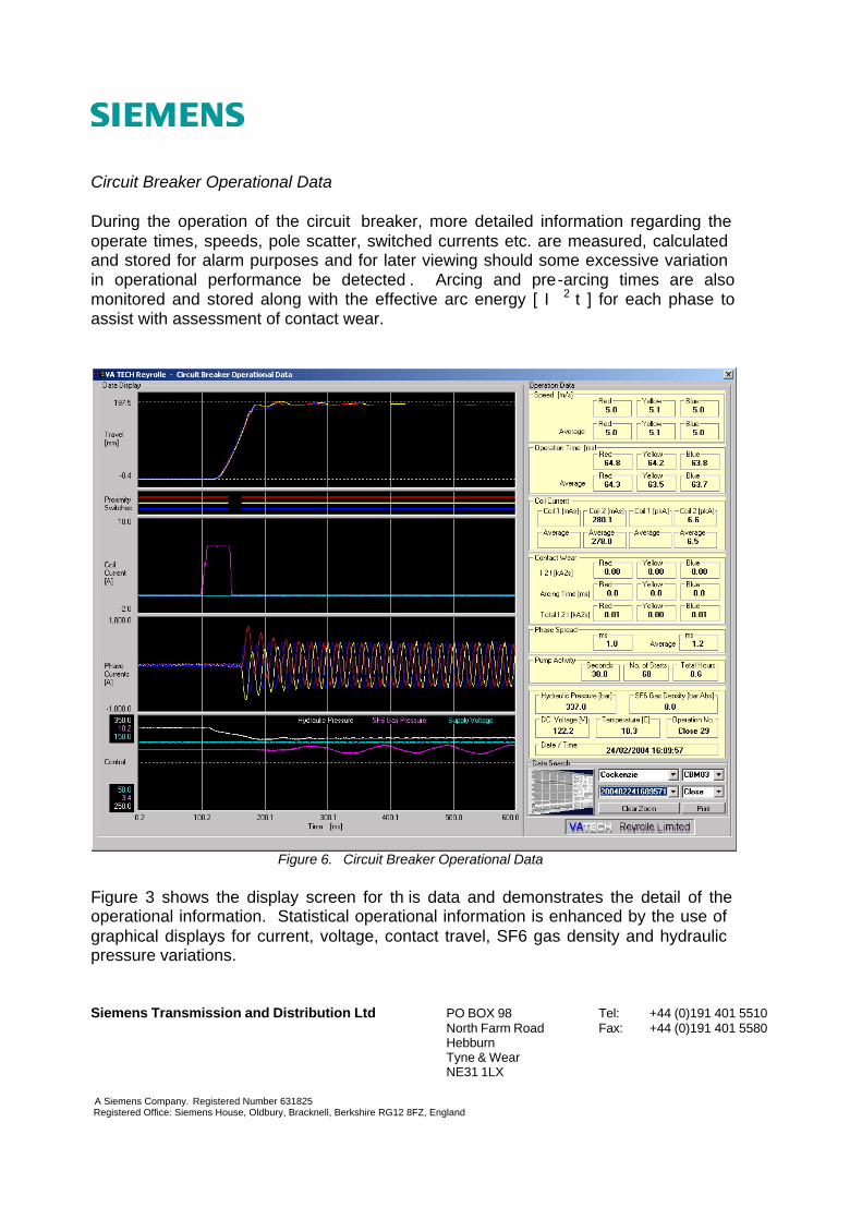
Circuit Breaker Operational Data During the operation of the circuit breaker, more detailed information regarding the operate times, speeds, pole scatter, switched currents etc. are measured, calculated and stored for alarm purposes and for later viewing should some excessive variation in operational performance be detected . Arcing and pre-arcing times are also monitored and stored along with the effective arc energy [ I 2 t ] for each phase to assist with assessment of contact wear.
Figure 6. Circuit Breaker Operational Data
Figure 3 shows the display screen for th is data and demonstrates the detail of the operational information. Statistical operational information is enhanced by the use of graphical displays for current, voltage, contact travel, SF6 gas density and hydraulic pressure variations.

Siemens Transmission and Distribution Ltd PO BOX 98 Tel: +44 (0)191 401 5510 North Farm Road Fax: +44 (0)191 401 5580 Hebburn Tyne & Wear NE31 1LX
A Siemens Company. Registered Number 631825 Registered Office: Siemens House, Oldbury, Bracknell, Berkshire RG12 8FZ, England
Remote Access Remote access to the CBM Control Cubicle is very much dependent on the infrastructure available at the substation. The most common form of access is via a modem but it is possible to also use a Local or Wide Area Network to gain access to the data. The remote access options are explored with each individual customer to define the best possible solution to implement in each case
Siemens Transmission and Distribution Ltd PO BOX 98 Tel: +44 (0)191 401 5510 North Farm Road Fax: +44 (0)191 401 5580 Hebburn Tyne & Wear NE31 1LX
A Siemens Company. Registered Number 631825 Registered Office: Siemens House, Oldbury, Bracknell, Berkshire RG12 8FZ, England
Appendix 1

Siemens Transmission and Distribution Ltd PO BOX 98 Tel: +44 (0)191 401 5510 North Farm Road Fax: +44 (0)191 401 5580 Hebburn Tyne & Wear NE31 1LX
A Siemens Company. Registered Number 631825 Registered Office: Siemens House, Oldbury, Bracknell, Berkshire RG12 8FZ, England
Factory Test Arrangement for Circuit Breaker Testing
Substation Monitor configured as Circuit Breaker Monitor for AIS [Located in 420kV LCC]
Circuit Breaker Monitor Front View

Siemens Transmission and Distribution Ltd PO BOX 98 Tel: +44 (0)191 401 5510 North Farm Road Fax: +44 (0)191 401 5580 Hebburn Tyne & Wear NE31 1LX
A Siemens Company. Registered Number 631825 Registered Office: Siemens House, Oldbury, Bracknell, Berkshire RG12 8FZ, England
Circuit Breaker Monitor and Transducer Terminations in 420kV LCC
Circuit Breaker Monitor Rear View

Siemens Transmission and Distribution Ltd PO BOX 98 Tel: +44 (0)191 401 5510 North Farm Road Fax: +44 (0)191 401 5580 Hebburn Tyne & Wear NE31 1LX
A Siemens Company. Registered Number 631825 Registered Office: Siemens House, Oldbury, Bracknell, Berkshire RG12 8FZ, England
Typical Circuit Breaker Monitor Trip Record [Full Record]
Typical Circuit Breaker Monitor Trip Record [Zoom Active]