side crash protection improvements through the use of an ... · fig 6: struck vehicle pulse with...
TRANSCRIPT

9. LS-DYNA Forum, Bamberg 2010
© 2010 Copyright by DYNAmore GmbH
Side Crash Protection Improvements Through the Use of an Active Door System
José Pedro Sousa Dias
ACTS – Advanced Car Technology Systems, Sailauf, Germany
Summary: The improvements in frontal crash safety registered in the last decade have been considerable, however, these improvements could only be partially transferred to the area of side crash. This accounts for part of the reasons why this type of accident became more relevant in the mortality accident statistics during the past few years. Automotive vehicle occupant protection in side and frontal crashes are problems of a different nature, as the available crush space for occupant acceleration / deceleration is quite different in the two scenarios. This paper presents an innovative pre-crash side impact protection concept based on the use of an active door which addresses this problem. Through the deployment of an outside airbag the acceleration and velocity intrusion profiles of the struck vehicle are changed in a way that enables the better use of the available interior space for a more efficient protection of the occupants. Numerical simulation using LS-Dyna and Madymo coupled analysis was performed in order to design the active door components, to adjust the complete side crash restraint system to the newly acquired protection potential and to quantify the level of safety improvement offered to the driver of a small vehicle. The work presented here concentrates on the IIHS side impact scenario for which the active door system brings significant improvements in the dummy thorax injury criteria. Keywords: Side crash, Integrated safety, Pre-crash
Passive Sicherheit II
D - II - 3

9. LS-DYNA Forum, Bamberg 2010
© 2010 Copyright by DYNAmore GmbH
1 Introduction
Side crash is a type of accident which as became increasingly relevant in the accident statistics in the past few decades. From the occupant protection point of view, this type of accident is characterised by: 1) reduced struck vehicle crush zone, 2) small space available for occupant acceleration and 3) small amount of occupant cushioning, which manifests itself trough the existence of occupant contact with hard vehicle parts (due to airbag bottoming-down) and direct force transmission to occupant delicate body regions, namely to the rib case. Due to this mix of characteristics, side crash posses a difficult engineering challenge, for which innovative solutions are needed in order to achieve the same level of occupant protection which is nowadays available for frontal crash. Significant improvements would be brought to the side crash scenario by addressing the three points mentioned above. This was the aim of the project carried out at ACTS in cooperation with CADENCE during which an Active Door Module concept was developed and implemented in a function demonstrator prototype. The system was developed virtually using coupled numerical simulation between the solvers LS-Dyna and MADYMO for the IIHS-MDB side impact scenario. This crash scenario was selected as it is one of the most demanding load cases for lateral impact restraint system design available nowadays.
2 The Active Door Module
The Active Door Module makes use of the pre-crash deployment of an exterior airbag in order to accomplish an increase of the struck vehicle’s crush zone, contributing in this way to the better shaping of the crash pulse. The use of pre-crash deployment also for the interior side crash airbag allows the better use of the available space between the occupant and the door trim and brings advantages for the occupant cushioning. The system concept is illustrated in Fig. 1.
Fig 1: Active Door Module system concept. The system was developed as a module, capable of being adapted and tuned for individual vehicles provided that the vehicle’s door outside panel can be adapted in order to provide the possibility of opening the exterior airbag. The Active Door Module consists of a plastic airbag support plate which is mounted on a supporting steel beam which works also as a door reinforcement. The exterior airbag and the associated gas-generator are mounted in the corresponding cavities on the supporting plate. Fig. 2 illustrates the Module construction. The module is them mounted to the door structure being supported on the door frame and existent side protection beam.
Passive Sicherheit II
D - II - 4

9. LS-DYNA Forum, Bamberg 2010
© 2010 Copyright by DYNAmore GmbH
Fig 2: The Active Door Module and the Active Door Module mounted in the door.
3 Setup of the simulation model
For concept demonstration purposes it was decided to carry out a product development and integration project for a fictitious vehicle. This virtual vehicle should correspond to the small car class and integrate the door of the Smart ForTwo, since this door was developed at ACTS and therefore the knowhow necessary for the elaboration of the detailed numerical model was in house. The parts necessary for the realistic evaluation of the vehicle’s side crash performance were modelled and attached to the body-in-white. These were the wheels, suspension, doors, seat and side impact restraint system, as show in figure 3. The total vehicle mass and centre of gravity were adjusted in order to be representative of cars in its class. The side impact restraint system with which the vehicle was equipped consisted of a seat belt and a thorax airbag. Dummy and barrier positioning were carried out according to the IIHS protocol [1].
Fig 3: The virtual vehicle used as basis for the development. The vehicle, the restraint system, the Active Door Module and the barrier were modelled in LS-Dyna. The SID-IIs Dummy and its contacts to the vehicle interior were modelled in MADYMO (extended coupling). The executable for coupling of LS-Dyna version 971d R2 7600.1224 and MADYMO version 7.1sp1 were used on a Xeon platform under Linux Suse 10.0 operative system. One of the main issues which a user of a coupled model has to face, is the fact that the LS-Dyna and the MADYMO sub-models will often be in two different systems of units. In fact, length dimensions are most usually given in millimetres for vehicle finite element models, while they can only be specified in meters for MADYMO models. This issue is handled transparently for the user in the computation itself, being only required that the appropriate conversion factors are given in the LS-Dyna input deck trough the inclusion of the corresponding *CONTROL_COUPLING keyword parameters, it requires however an additional step in pre-processing, as the dummy skin has to be scaled back to millimetres in order to allow the efficient execution of tasks like the elimination of seat to dummy initial penetrations and
Passive Sicherheit II
D - II - 5

9. LS-DYNA Forum, Bamberg 2010
© 2010 Copyright by DYNAmore GmbH
fitting the seat-belt to the dummy. These tasks are however accomplished easily with the use of appropriate pre-processing software.
Fig 4: A dummy model scaled to millimetres was required for pre-processing activities The definition of the contact interfaces takes place in two steps. In LS-Dyna it is necessary to define which PIDs will be exported for contact calculation by using the *CONTACT_COUPLING keyword, while the definition of the contact pairs and the assignment of contact characteristics takes place in the MADYMO input deck. In order to keep the contact computation time and memory use at acceptable levels, a selective choice of the PIDs to be included in the *CONTACT_COUPLING set was performed, together with a careful definition of the contact pairs. In fact the contact search algorithm used in MADYMO was not as efficient as the one to which LS-Dyna users are accustomed to, making it preferable to define a number of contact pairs including few neighbouring parts which will probably come in contact with each other, in comparison to have contact pairs which include dummy regions and PIDs which will most likely not come into contact. For the application case, the contact definition was made using node to surface contacts that take into account the dummy flesh compliance and by using 21 contact pairs as shown in Fig. 5. Master Slave Master Slave
/Driver/Jacket_gfe SeatBelt /Driver/Head_gfe HeadRest
/Driver/Pelvis_gfe SeatBelt /Driver/Pelvis_gfe DoorTrim
/Driver/Neck_gfe SeatBelt /Driver/FemurKneeL_gfe DoorTrim
/Driver/Pelvis_gfe Buckel /Driver/TibiaL_gfe DoorTrim
/Driver/Pelvis_gfe Seat /Driver/ShoeL_gfe DoorTrim
/Driver/FemurKneeL_gfe Seat /Driver/Jacket_gfe DoorTrim
/Driver/FemurKneeR_gfe Seat /Driver/Head_gfe SideAirbag
/Driver/TibiaL_gfe Seat /Driver/Arm_gfe SideAirbag
/Driver/TibiaR_gfe Seat /Driver/Jacket_gfe SideAirbag
/Driver/Arm_gfe Seat /Driver/ShoeL_gfe BIW_PID
/Driver/Jacket_gfe Seat Fig 5: Contact pairs definition.
4 System development and tune-up trough numerical simulation
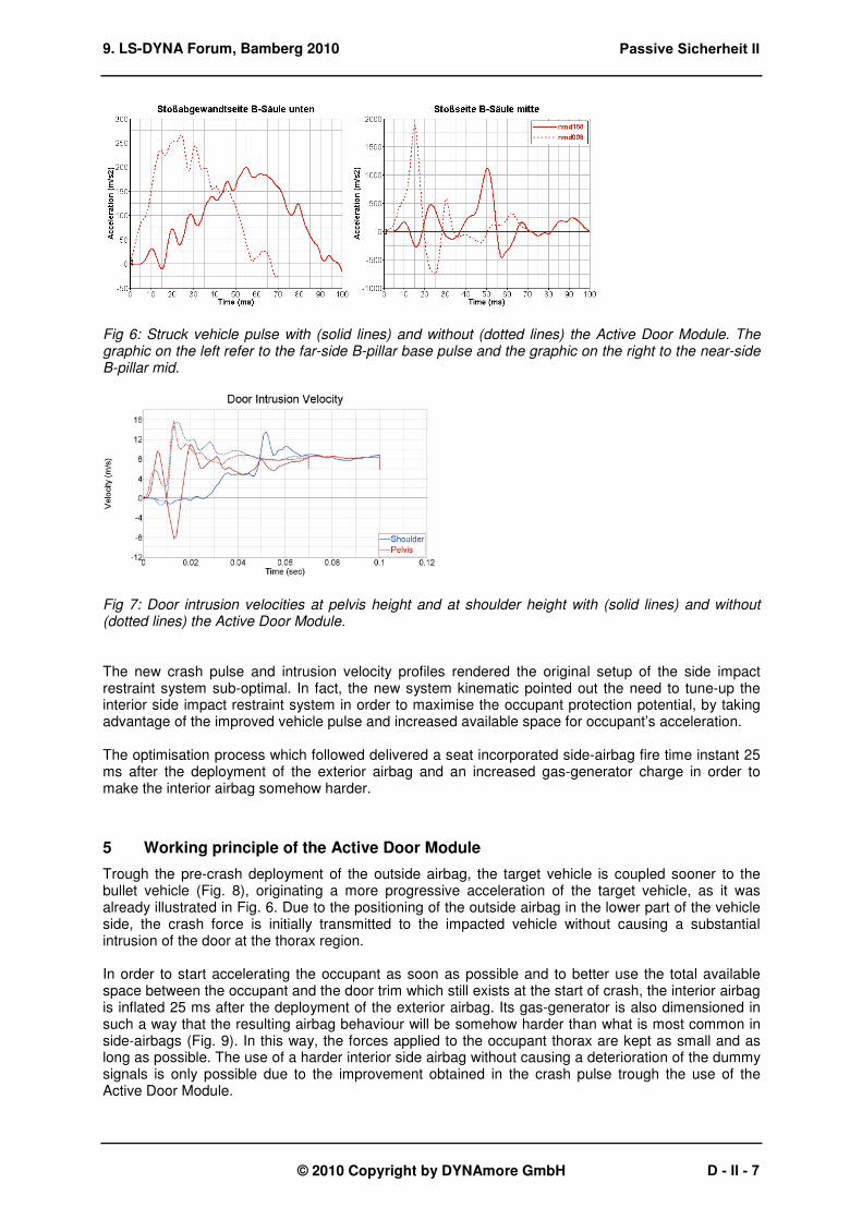
The system pre-crash exterior airbag deployment time instant was fixed at the begin of the project at 30 ms, which corresponds to a distance between the struck vehicle and the oncoming vehicle of 0.42 meters when this last vehicle is travelling at the IIHS-test speed velocity of 50 km/h. By choosing this pre-crash interval, enough time was left available to fill the exterior airbag properly and the demands on airbag size and generator power were kept reasonable. Simulation runs were used to evaluate the protection potential of the Active Door Module and to setup the physical parameters of the system, such as geometrical and gas-generator characteristics. This process was guided by the assessment of the changes in the struck vehicle crash pulse and door intrusion velocities. The improvements observed for the system final configuration are illustrated in Fig. 6 and 7 and demonstrate a significant potential to reduce the crash severity for the struck vehicle occupants.
Passive Sicherheit II
D - II - 6
9. LS-DYNA Forum, Bamberg 2010
© 2010 Copyright by DYNAmore GmbH
Fig 6: Struck vehicle pulse with (solid lines) and without (dotted lines) the Active Door Module. The graphic on the left refer to the far-side B-pillar base pulse and the graphic on the right to the near-side B-pillar mid.
Fig 7: Door intrusion velocities at pelvis height and at shoulder height with (solid lines) and without (dotted lines) the Active Door Module. The new crash pulse and intrusion velocity profiles rendered the original setup of the side impact restraint system sub-optimal. In fact, the new system kinematic pointed out the need to tune-up the interior side impact restraint system in order to maximise the occupant protection potential, by taking advantage of the improved vehicle pulse and increased available space for occupant’s acceleration. The optimisation process which followed delivered a seat incorporated side-airbag fire time instant 25 ms after the deployment of the exterior airbag and an increased gas-generator charge in order to make the interior airbag somehow harder.
5 Working principle of the Active Door Module
Trough the pre-crash deployment of the outside airbag, the target vehicle is coupled sooner to the bullet vehicle (Fig. 8), originating a more progressive acceleration of the target vehicle, as it was already illustrated in Fig. 6. Due to the positioning of the outside airbag in the lower part of the vehicle side, the crash force is initially transmitted to the impacted vehicle without causing a substantial intrusion of the door at the thorax region. In order to start accelerating the occupant as soon as possible and to better use the total available space between the occupant and the door trim which still exists at the start of crash, the interior airbag is inflated 25 ms after the deployment of the exterior airbag. Its gas-generator is also dimensioned in such a way that the resulting airbag behaviour will be somehow harder than what is most common in side-airbags (Fig. 9). In this way, the forces applied to the occupant thorax are kept as small and as long as possible. The use of a harder interior side airbag without causing a deterioration of the dummy signals is only possible due to the improvement obtained in the crash pulse trough the use of the Active Door Module.
Passive Sicherheit II
D - II - 7

9. LS-DYNA Forum, Bamberg 2010
© 2010 Copyright by DYNAmore GmbH
Fig 8: The exterior airbag couples both vehicles sooner, transferring forces to the lower part of the struck vehicle. The improvement of the vehicle acceleration and door intrusion velocity profiles are promoted in this way.
Fig 9: The Active Door Module enables the better use of the available space between the occupant and the door trim. Improvements in the pelvic region are achieved trough the choice of adequate module geometrical features for the Active Door Module, as for example the placement of the gas-generator, and use of adequate seat pushers as illustrated in Fig. 10. In this way, it was possible to build an adequately supported soft region in the door trim corresponding to the occupant pelvis without making any changes to the door trim itself. In combination with the improved vehicle pulse, this results in an effective but gentle push of the occupant pelvis.
Fig 10: Trough the appropriate placement of the Active Door Module geometrical features, improvements are obtained for the pelvis region.
Passive Sicherheit II
D - II - 8

9. LS-DYNA Forum, Bamberg 2010
© 2010 Copyright by DYNAmore GmbH
6 Active Door Module Performance
The optimised side impact protection system delivered no bottoming-down of the dummy’s shoulder rib, a maximal rib deflection of 280 mm and an average rib deflection of 187 mm. The combined pelvic force value was 3.08 kN. These results are summarised in Figs. 11 and 12. These results correspond to an improvement of about 30% in the thoracic region and of about 25% for the pelvic combined force, when compared with the values obtained for the vehicle when not equipped with the Active Door Module.
Fig 11: Rib deflection and pelvic forces versus time for the original vehicle (upper graphics) and for the vehicle equipped with the Active Door Module (lower graphics).
For reference, figure 12 presents also the classification obtained in the IIHS test by the Smart ForTwo [2]. This production vehicle belongs to the vehicle class of the virtual vehicle used for this work and performs well according to the IIHS criteria.
0,00
0,01
0,02
0,03
0,04
0,05
0,06
RIB
SD
S.m
ax
RIB
SD
S.a
vr
AC
TB
FO
Y
ILA
CF
OY
AC
ILF
OY
0
1000
2000
3000
4000
5000
0,00
0,01
0,02
0,03
0,04
0,05
0,06
RIB
SD
S.m
ax
RIB
SD
S.a
vr
AC
TB
FO
Y
ILA
CF
OY
AC
ILF
OY
0
1000
2000
3000
4000
5000
0,00
0,01
0,02
0,03
0,04
0,05
0,06
RIB
SD
S.m
ax
RIB
SD
S.a
vr
AC
TB
FO
Y
ILA
CF
OY
AC
ILF
OY
0
1000
2000
3000
4000
5000
Fig 12: Injury criteria for the thoracic and pelvic regions with (left) and without (centre) the Active Door Module. Smart ForTwo values are presented as reference (right).
Passive Sicherheit II
D - II - 9

9. LS-DYNA Forum, Bamberg 2010
© 2010 Copyright by DYNAmore GmbH
7 Conclusion
A new pre-crash concept for side impact occupant protection was developed based on an Active Door Module. This concept makes use of an exterior airbag capable of coupling sooner the kinematic of the struck vehicle to the one of the oncoming vehicle, resulting in reduced maximal vehicle acceleration values. Trough the tune up of the complete side impact restraint system, improvements of about 30% were observed for the dummy thoracic values and of about 25% for the dummy pelvic values. Such improvements are a considerable contribution to the improvement of the level of occupant protection in side crash and might became essential in view of legislation and consumer test refinements that might happen in the future. In order to be able to demonstrate the working principle and easy vehicle integration a function demonstrator was built and is depicted in figure 13.
Fig 13: Active Door Module function demonstrator.
8 Literature
[1] Insurance Institute for Highway Safety, Side Impact Crashworthiness Evaluation, Crash Test Protocol (Version V), Arlington, USA, 2008
[2] Insurance Institute for Highway Safety, Side Impact Crashworthiness Evaluation, Crash Test
Report, 2008 Smart ForTwo (CES0815), Arlington, USA, 2008
Passive Sicherheit II
D - II - 10