side by side cassinetta production 25cf with idi 2 range …€¦ · side by side cassinetta...
TRANSCRIPT

Version 1.0
Side by Side Cassinetta production
Whirlpool EMEA
Service Competence Center
Office +49-(0)711-81071-3550
Mobile +49-(0)160-90513592
Robert Zimmermann
Senior Service Engineer FSS
25cf with IDI 2
Range 2012

Chapter list
Installation
Safety Instruction
Installation Instruction
Range 2012 overview
Whirlpool appliance launch / Flat / IDI 2
Whirlpool / Flat / IDI 2 / Spring INOX
Whirlpool / Flat / IDI 2 / INOX
Whirlpool / Flat / IDI 2 / Global White
Novelties
Operations
General description of the User Interface
User Interface layout of dispenser “with paddle”
Display icons
Indication of Water Filter
Indication of Antibacterial Filter
Characteristics of settings: Eco Modus
Characteristics of settings: Listeria Indication
Buttons description
“Virtual Key‟s” on7-segment
Biruni User Interface Alarm indications
Biruni User Interface failure indications
Long Black Out Alarm algorithm
Thermostatic function
Components
3D Multiflow with Antibacterial filter
Multiflow with graph “6° sense”
Chapter list
Troubleshooting
Board failure codes description
Board self test
Alarm summery
Failure codes summery
Activation of the “Built-In” Test Routine
“Built-In” Test Operations and Code Summery
“Built-In” Test Error Codes Summery
Filter reset after “Built-In” test sequence
Documents: Manuals, NTC value table, SB‟s
Repair Guide Line
Disassembling Long Door Handle
Disassembling 3 D Multiflow
Disassembling Flow Channel
Disassembling User Interface with I&W
Disassembling Ice Crusher Motor IDI 2
Disassembling Sankyo IDI ice-maker
Disassembling ice-maker water tube
Functional characteristics
Main Control Board description
NTC sensor in the refrigerator compartment
Damper control
NTC sensor in the freezer compartment
NTC sensor failure management
Ice-Water valve
Ice-Maker water valve
Ice-Maker
Dispenser lamp
Dispenser stepper motor
Dispenser heater
Dispenser paddles
Sankyo IDI / Biruni 7-segment UI
Evaporator Defrost Cycle

Chapter list
Technical Data
Main Board
User Interface
Stepper Motor dispenser assembly
Dispenser paddle
Dispenser LED
Ice Motor IDI 2
Lamps
Defrost Heater R134a
Fan Motors
Air Diffuser
Ice Maker Sankyo IDI 2
Water valve

Installation
Safety Instruction
IFU for SxS „Nova“ Whirlpool Range
Attention:
• Carefully read the complete safety and operation instructions in the IFU (attached below).
• Attend the environmental regulations.
• Keep the healthy instructions, especially for the assembler and children.
• Read the Installation instruction before first installation.
Quick Start Guide for BIRUNI electronics

Installation
Installation Instruction
Installation Instruction.
Attention:
• Read the complete installation instructions in the IFU (attached below).
• Be careful to avoid damages on the appliance, at the facility or injuries at the people.
• Attend the installation information to ensure the proper functionality of the appliance.
Appliance and niche measurement of SxS „Nova“ – 25cf / 715.

12NC Commercial Code Predecessor 12NC
858646201000 WSE 2930 W 858642201000
858646201070 WSE 2930 X 858642201010
858646211000 WSF7256 A+W 858642211010
858646211070 WSF7256 A+IX 858642211000
858646215070 WSF7256 A+IX 858642215000
858646279100 WSF 7656 W 858619779010
858646279130 WSF 7656 X 858619779000
858646211170 WSF7256 IX no predeccessor
858646211100 WSF7256 W no predeccessor
Range 2012 overview
Whirlpool appliance launch / Flat / IDI2

Range 2012 overview
Whirlpool / Flat / IDI2 / Spring INOX
WSE 2930X / 8586 462 01070 / A+ / R134a
Doors: Flat, Spring Inox (968804), door end-caps in grey (10961)
Cabinet: Universal Silver (10979)
Handles: Pillar handle Alu Scotch Bright (10995) with
handle support painted grey (10961)
User Interface: Policarbonate in grey with bottons in grey (10961).
LED„s with color white.
Dispenser: Dispenser frame in grey (10961), electronic paddles
(grey 10961), water tray Inox, spigot dispenser in grey
Plinth: plinth in grey (10961) with cover filter in black (80127)
Shelves fridge: Co-injected and one bottle rack (wire grid in Inox)
Door bins fridge: one flap, four balcony 2 without / 2 with wire,
one wine balcony
Drawers fridge: one snack crisper, one vegetable crisper,
one meat crisper
Shelves freezer: three wire grid, two with small basket
Door bins freezer: two snap-on balcony
Drawers freezer: upper and lower basket
Ice making system: IDI 2 version (Sankyo)
Features: Mini Multiflow in the top with milky Multiflow (with graph
"6° sense - Multi Sensor Technology“),
Listeria and Antibacterial Filter

Range 2012 overview
Whirlpool / Flat / IDI2 / Spring INOX
WSF 7256IX / 8586 462 11170 / A+ / R134a
Doors: Flat, Spring Inox (968804), door end-caps in grey (10961)
Cabinet: Universal Silver (10979)
Handles: Pillar handle Alu Scotch Bright (10995) with
handle support painted grey (10961)
User Interface: Policarbonate in grey with bottons in grey (10961).
LED„s with color white.
Dispenser: Dispenser frame in grey (10961), electronic paddles
(grey 10961), water tray Inox, spigot dispenser in grey
Plinth: plinth in grey (10961) with cover filter in black (80127)
Shelves fridge: Co-injected and one bottle rack (wire grid in Inox)
Door bins fridge: one flap, four balcony without wire,
one wine balcony
Drawers fridge: one snack crisper, one vegetable crisper,
one meat crisper
Shelves freezer: three wire grid, two with small basket
Door bins freezer: two snap-on balcony
Drawers freezer: upper and lower basket
Ice making system: IDI 2 version (Sankyo)
Features: Mini Multiflow in the top with milky Multiflow (with graph
"6° sense - Multi Sensor Technology“),
Antibacterial Filter

Range 2012 overview
Whirlpool / Flat / IDI2 / INOX
WSF 7656X / 8586 462 79130 / A / R134a
Doors: Flat, Inox (10903), door end-caps in grey (10961)
Cabinet: Universal Silver (10979)
Handles: Pillar handle Alu Scotch Bright (10995) with
handle support painted grey (10961)
User Interface: Policarbonate in grey with bottons in grey (10961).
LED„s with color white.
Dispenser: Dispenser frame in grey (10961), electronic paddles
(grey 10961), water tray Inox, spigot dispenser in grey
Plinth: plinth in grey (10961) with cover filter in black (80127)
Shelves fridge: Co-injected and one bottle rack (wire grid in Inox)
Door bins fridge: one flap, four balcony two with wire,
one wine balcony
Drawers fridge: one snack crisper, one vegetable crisper,
one meat crisper
Shelves freezer: three wire grid, two with small basket
Door bins freezer: two snap-on balcony
Drawers freezer: upper and lower basket
Ice making system: IDI 2 version (Sankyo)
Features: Mini Multiflow in the top with milky Multiflow (with graph
"6° sense - Multi Sensor Technology“),
Antibacterial Filter, Shuko plug

Range 2012 overview
Whirlpool / Flat / IDI2 / Global White
WSE 2930 W / 8586 462 01000 / A+ / R134a
Doors: Flat, white (90201), door end-caps in white (90201)
Cabinet: Global White (90201)
Handles: Pillar handle Alu Scotch Bright (10995) with
handle support painted grey (10961)
User Interface: Policarbonate in grey with bottons in white (90201).
LED„s with color white.
Dispenser: Dispenser frame in white (90201), electronic paddles
(grey 10789), water tray Inox, spigot dispenser in white
Plinth: plinth in white (90201) with cover filter in white (90201)
Shelves fridge: Co-injected and one bottle rack (wire grid in Inox)
Door bins fridge: one flap, four balcony two with wire,
one wine balcony
Drawers fridge: one snack crisper, one vegetable crisper,
one meat crisper
Shelves freezer: three wire grid, two with small basket
Door bins freezer: two snap-on balcony
Drawers freezer: upper and lower basket
Ice making system: IDI 2 version (Sankyo)
Features: Mini Multiflow in the top with milky Multiflow (with graph
"6° sense - Multi Sensor Technology“),
Antibacterial Filter, Listeria

Range 2012 overview
Whirlpool / Flat / IDI2 / Global White
WSF 7256 W / 8586 462 11100 / A / R134a
Doors: Flat, white (90201), door end-caps in white (90201)
Cabinet: Global White (90201)
Handles: Pillar handle Alu Scotch Bright (10995) with
handle support painted grey (10979)
User Interface: Policarbonate in grey with bottons in white (90201).
LED„s with color white.
Dispenser: Dispenser frame in white (90201), electronic paddles
(grey 10789), water tray Inox, spigot dispenser in grey
Plinth: plinth in white (90201) with cover filter in white (90201)
Shelves fridge: Co-injected and one bottle rack (wire grid in Inox)
Door bins fridge: one flap, four balcony without wire,
one wine balcony
Drawers fridge: one snack crisper, one vegetable crisper,
one meat crisper
Shelves freezer: three wire grid, two with small basket
Door bins freezer: two snap-on balcony
Drawers freezer: upper and lower basket
Ice making system: IDI 2 version (Sankyo)
Features: Mini Multiflow in the top with milky Multiflow (with graph
"6° sense - Multi Sensor Technology“),
Antibacterial Filter

WSF 7656 W / 8586 462 79100 / A+ / R134a
Doors: Flat, white (90201), door end-caps in white (90201)
Cabinet: Global White (90201)
Handles: Pillar handle Alu Scotch Bright (10995) with
handle support painted grey (10979)
User Interface: Policarbonate in grey with bottons in white (90201).
LED„s with color white.
Dispenser: Dispenser frame in white (90201), electronic paddles
(grey 10789), water tray Inox, spigot dispenser in grey
Plinth: plinth in white (90201) with cover filter in white (90201)
Shelves fridge: Co-injected and one bottle rack (wire grid in Inox)
Door bins fridge: one flap, four balcony without wire,
one wine balcony
Drawers fridge: one snack crisper, one vegetable crisper,
one meat crisper
Shelves freezer: three wire grid, two with small basket
Door bins freezer: two snap-on balcony
Drawers freezer: upper and lower basket
Ice making system: IDI 2 version (Sankyo)
Features: Mini Multiflow in the top with milky Multiflow (with graph
"6° sense - Multi Sensor Technology“),
Antibacterial Filter, Shuko plug
Whirlpool / Flat / IDI2 / Global White
Range 2012 overview

Range 2012
Novelties
1. New IDI (In Door Ice) Sankyo ice-maker.

Range 2012
Novelties
2. Electronic paddle dispenser version.
3. New multiflow channel in fridge compartment.

Range 2012
Novelties
5. New upper hinge with „cut-out“
for a door exchange without
removing the connectors and
modified top connectors with
pin lock system.
6. New water piping guidance for
the ice-maker. Both pipes are
now located in the base of the
appliance.
Blue pipe for the ice-maker
Transparent pipe for the ice-water

- General description of the User Interface
- UI layout of dispenser with paddle
- Display icons
- Indication of Water Filter
- Indication of Antibacterial Filter
- Characteristics of settings: Eco Modus
- Characteristics of settings: Listeria Indication
- Buttons description
- “Virtual Key‟s” on 7-segment
- Biruni User Interface Alarm indications
- Biruni User Interface failure indications
- Long Black Out Alarm algorithm
- Thermostatic function
Operations

Operation
General description of the User Interface
The function of the User Interface is to provide to the User which functions are active and/or selectable and if
there is some failure or alarm condition. Some loads (such as heater, paddle switch, step motor) will be driven
directly by the User Interface Board, but according to Control Board instruction; no logic will reside in the board.
7-segment IDI/NO IDI Biruni
Expected life:
The equipment shall have a useful life not less
than 15 years, corresponding to:
- 10.000 pushbutton operating cycles
- LED life for 15 years
- Buzzer life for 2000 hr. continuous
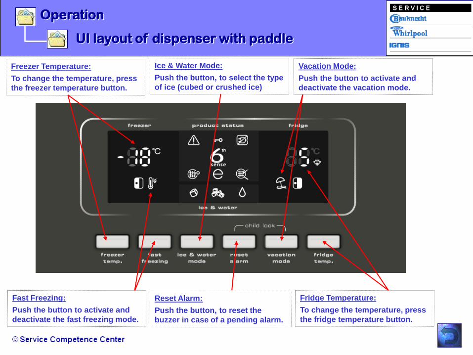
Operation
Vacation Mode:
Push the button to activate and
deactivate the vacation mode.
Freezer Temperature:
To change the temperature, press
the freezer temperature button.
Fast Freezing:
Push the button to activate and
deactivate the fast freezing mode.
Ice & Water Mode:
Push the button, to select the type
of ice (cubed or crushed ice)
Reset Alarm:
Push the button, to reset the
buzzer in case of a pending alarm.
Fridge Temperature:
To change the temperature, press
the fridge temperature button.
UI layout of dispenser with paddle

Operation
“Listeria” Thermometer Indicator
Black-Out Alarm 6th Sense Function
Refrigerator Open Door Alarm Freezer Open Door Alarm
Eco-Mode
Antibacterial Filter Indication Water Filter Indication
Water Delivery Icon
Alarm Icon
Control Panel Lock (Child Lock)
UI layout of dispenser with paddle
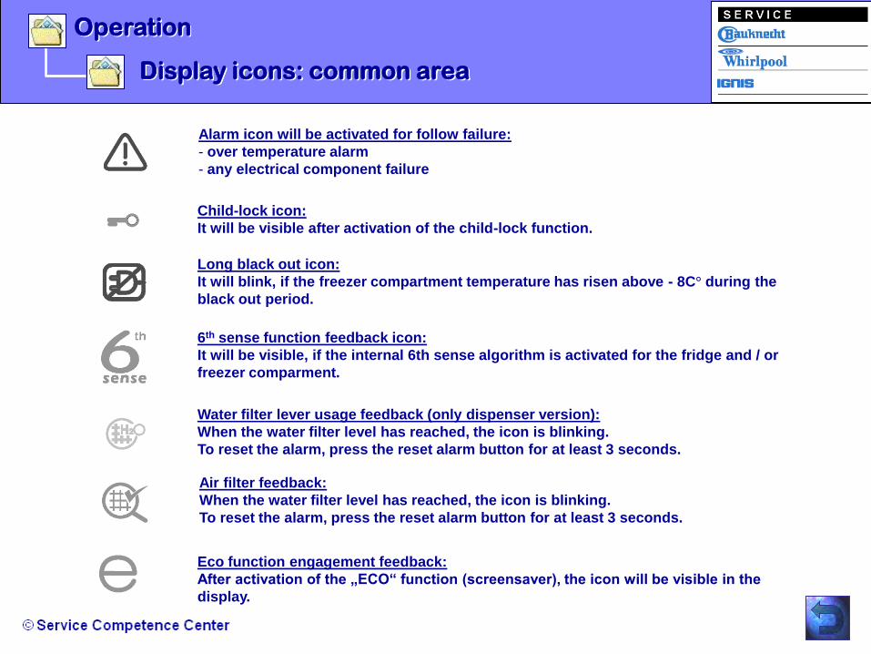
Operation
Display icons: common area
Eco function engagement feedback:
After activation of the „ECO“ function (screensaver), the icon will be visible in the
display.
Air filter feedback:
When the water filter level has reached, the icon is blinking.
To reset the alarm, press the reset alarm button for at least 3 seconds.
Water filter lever usage feedback (only dispenser version):
When the water filter level has reached, the icon is blinking.
To reset the alarm, press the reset alarm button for at least 3 seconds.
6th sense function feedback icon:
It will be visible, if the internal 6th sense algorithm is activated for the fridge and / or
freezer comparment.
Long black out icon:
It will blink, if the freezer compartment temperature has risen above - 8C° during the
black out period.
Child-lock icon:
It will be visible after activation of the child-lock function.
Alarm icon will be activated for follow failure:
- over temperature alarm
- any electrical component failure

Operation
Display icons: freezer compartment area
Fast Freezing function:
It controls consequently the compressor, compressor fan and
evaporator fan. The freezer compartment will be cooled down
independently of the temperature settings. The Fast freezing function
expired automatically after 24 hours after activation.
Freezer compartment door status:
The alarm will be activated after the freezer door was open longer than 2
minutes. The buzzer sounds and the icon in the UI is blinking.
Freezer compartment set point digits:
It will be managed by the set Up/Down push button.
For each pressing you increase / decrease the temperature value
in 1°C steps. The range is from -18°C ( factory setting ) till -24°C.

Operation
Display icons: refrigerator compartment area
Listeria feedback:
The symbol indicates you the right temperature inside the refrigerator
compartment and allow you to control the optimum average temperature
in the whole compartment.
Vacation function engagement:
This function is a stand-by modus of the refrigerator compartment. If the
function is activated, the damper goes in open position for 2 minutes and
the evaporator fan is also activated. This operation will be repeated every
30 minutes. This routine avoid strong smell in the fridge if it„s not used.
Refrigerator compartment door status:
The alarm will be activated after the fridge door was open longer than
2 minutes. The buzzer sounds and the icon in the UI is blinking.
Refrigerator compartment set point digit:
It will be managed by the set Up/Down push button. For each pressing
you increase / decrease the temperature value in 1°C steps.
The range is from +2°C till +6°C ( factory setting ).

Operation
Display icons: dispenser area
Water dispensing mode icon (dispenser version)
Ice crushed dispensing mode icon (dispenser version)
Ice cubed dispensing mode icon (dispenser version)

Operation
Indication of Water Filter
By pressing the “reset alarm” button for at least 3 seconds the buzzer sounds one time. The water filter icon
switch back to the low usage state.
The water filter control will calculate and record the total volume of water flowed through the valve during the
opening periods. The flow rate for the dispenser water valve is 1,51 litres per minute (24-58 cc per second).
The total liters flow is calculated by using the flow rates for Ice Maker valve and Water Dispenser valve.
The litres of each valve flow rate is multipled by the corresponding open time. The total liters
will be obtained adding the liters of each valve. The liters and time usage data will be recorded even after
a power black out. These data will be updated daily.

Operation
Indication of Antibacterial Filter
7 – segment GREEN based display version: It‟s a 6 month (+/- 2 days) delay timer with 2 different states.
The states are:
- OFF , User Interface LED switched OFF (low usage)
- ON, User Interface LED switched ON (Alarm state after 180 days)
The timer will be stopped when the appliance is in Stand-by (OFF) condition.

The “Eco Modus” function can be used to save energy.
15 seconds after activating the Eco function the display goes OFF and only the
symbol is visible (like a screensaver).
Whenever the control panel is used (mainly water/ice, open a compartment door
etc.), the display will come back for 15 seconds. After 15 second it will go back to
the screensaver Mode and the ECO icon is visible.
Note: This function does not disconnect the appliance from the power supply.
Operation
Characteristics of settings: Eco Modus
Activation of “Eco Mode”:
1. Press the ice & water button and the reset alarm button at the same time for 4 seconds.
2. After the 4 seconds the “Eco” icon will turn ON and 11 seconds later the display turns OFF.
3. The buzzer sounds one time.
Deactivation of the “Eco Mode”:
1. Press the ice & water button and reset alarm button at the same time for 4 seconds.
2. After 4 seconds the “Eco” icon will turn OFF and 13 seconds later the display remain ON.
3. The buzzer sounds one time.
Note: If there exist a power supply interuption, the „Eco“ function is also deactivated.

Operation
Characteristics of settings: Listeria Indication
The internal temperature of the refrigerator depends on various factors like:
- the ambient temperature of the room
- the amount of food stored
- how often the door is opened.
These factors should be taken into account when setting the appliance.
IMPORTANT: After opening the door or loading the refrigerator, it is normal if the symbol is switched OFF
for some time, especially if room temperature is very warm.
Note: The Listeria indication is not in use till today.
The symbol indicates you the right temperature inside the refrigerator compartment and
allow you to control the optimum average temperature in the whole compartment.
To check the temperature the appliance has been switched ON for at least 24 hours!
After this time you can check if the temperature in the refrigerator compartment is correct and if necessry
adjust the temperature settings.
If the symbol is switched OFF, it means that the temperature inside the refrigerator is too warm. In this
case adjust the temperature setting and wait for at least 12 hours before checking again if the
temperature is correct.

Operation
Buttons description
Button 1: Freezer compartment temperature set, to increase or decrease the freezer compartment temperature.
Button 2: Fast Freezing function, to engage or disengage the fast freezing function for the freezer compartment.
Button 3: To toggle between the cubed and crushed ice (water dispensing will be always available).
Button 4: Reset Alarm, to reset the buzzer in case of a pending alarm.
Button 5: Refrigerator vacation function, to engage or disengage the vacation function.
Button 6: Refrigerator compartment temperature set, to increase or decrease the fridge compartment temperature.
Button 4 & 5:To lock or unlock all the User Interface (press at same time for 2 seconds)
1 3 2 4 5 6

Operation
“Virtual Key’s” on 7-segment
Virtual Key 1: Child Lock function for the User Interface:
To activate or deactivate the child lock function press the button “reset alarm” and “vacation mode
simultaneous for 2 seconds. This function is only available for appliance with dispenser unit.
Virtual Key 2: Niche Heater function:
To turn ON or OFF the niche heater in the dispenser area, press the button “fast freezing” and “reset
alarm” at the same time for 2 seconds. This function is only available for appliance with dispenser unit.
Virtual Key 3: Eco function:
To activate or deactivate the “Eco function” press the button ”ice & water mode” and “reset alarm” at
the same time for 2 seconds.

Operation
Biruni User Interface Alarm indications
Followed Alarm indication are visible in the User Interface:
- Freezer Door Alarm (Freezer Door icon blinking & buzzer sounds)
- Refrigerator Door Alarm (Refrigerator Door icon blinking & buzzer sounds)
- Antibacterial Filter Alarm (Air Filter icon blinking without buzzer)
- Water Filter Alarm (Water Filter icon blinking without buzzer)
- Over Temperature Alarm (Alarm icon blinking & buzzer)
- Long Black Out Alarm (Long Black Out Alarm icon & buzzer sounds)
- Failure (Alarm icon & buzzer sounds)
You will find the alarm summery in the chapter troubleshooting!

Operation
Biruni User Interface Failure Indications
Followed failure code will be indicated in the User Interface if exist:
- “UU” = wrong User Interface board (freezer display)
- “SF”= Freezer sensor (freezer display)
- “HF”= Ice maker SANKYO sensor (freezer display)
- “ F” = Refrigerator sensor (refrigerator display)
- “d” = Damper unreliable (refrigerator display)
- “F” = Refrigerator compartment (refrigerator display)
- “CF”= Communication failure (freezer display)
- “LF”= Production test not passed (freezer display)
You will find the failure code summery in the chapter troubleshooting!

Operation
Long Black Out Alarm Algorithm
Long black out check will be executed each power up only if the algorithm is enabled.
This alarm signal show a dangerous over temperature for goods (safety preservation limit).
It has been achieved during a main power failure.
This alarm will be activated:
- after a main power restoring if the appliance was in the ON condition when the black out occurred.
The electronic control must check the Freezer NTC temperature and activate the alarm if the
value inside the cavity has risen above - 8°C (-7,5°C or more) during the black out period.
That means that the temperature value at black out occurrence must be recorded and compared with the
temperature value at the moment of power restoring.
This alarm will perform the following operations:
a) display the highest temperature value (blinking) detected at the moment of main power restoring
b) the Alarm state icon for LCD and red LED for 7-segment will be send to the User Interface ;

Operation
Thermostatic function
The thermostatic function must control the unit to
keep the compartments temperature values set by the
user on the Control Panel.
Compressor, compressor fan, evaporator fan and
damper control is performed using the temperature
values measured through the 2 NTC sensors of the
unit. The evaporator is equipped with a defrost
heater. The cold airflow in the refrigerator
compartment is regulated opening or closing an
electrical damper.
The thermostatic function must be suspended during
a defrost procedure, it will be resumed after the
defrost end.

- 3D Multiflow with Antibacterial filter (top side)
- Multiflow with graph "6° sense - Multi Sensor Technology“
Components

Components
3D Multiflow with Antibacterial filter
3
Airflow to the balconies
Airflow to the shelves and drawers
Antibacterial filter
The efficiency of the refrigerator is optimised, because the temperature is always the same
everywhere.
The three air flow outlets convey the cold air in each compartment of the refrigerator, which
allow the temperature to be homogeneous among all the shelves. It brings the air till the last
bottom drawer and to the balconies.
2
1

Components
3D Multiflow with Antibacterial filter
1. The light unit is implemented in the 3D Multiflow .
2. Antibacterial filter
3. New milky Multiflow (with graph "6° sense - Multi Sensor Technology“),
1. 2.
3.

Components
Multiflow with graph "6° sense”
The new multiflow with
graph “6° sence” is fixed
with four screws behind the
milky flow cover. The right
pictures shows you the inlet
and outlet channels for the
air distribution to each
shelf.

Components
Multiflow with graph "6° sense”
1. Step: Remove all shelf‟s 3. Step: after the hook is released, lift
up the complete milky cover to remove
it. See the fixation hooks below.
2. Step: Lift up the hook
below the transparent air
channel cover as shown.

- Main Control Board description
- NTC sensor in the refrigerator compartment
- Damper control
- NTC sensor in the freezer compartment
- NTC sensor failure management
- Ice-Water valve
- Ice-Maker
- Ice-Maker water valve
- Ice-Crusher motor Value Line
- Dispenser lamp
Functional characteristics
- Dispenser stepper motor
- Dispenser heater
- Dispenser paddles
- IDI Biruni 7-segment UI
- VL (No IDI) Biruni 7-seg.
- No Dispenser UI
- Evaporator Defrost Cycle

Functional characteristics
Main Control Board description
The Main Board is located in the compressor area and communicate to the User Interface board.
The Main Control Board is installed on Side by Side appliances with In Door Ice Ice- Maker system (current Ice-
Maker) or NOT IDI Ice-Maker system (Ice-Maker Sankyo).
The product is a two compartments (refrigerator and freezer), one compressor automatic defrost appliance.
The main function of electronics is to manage the temperature inside the cavities and to manage the Ice and
Water dispenser controlling consequently the compressor and the other components operations.
The electronic control architecture is as follow:
7-segment IDI/NO IDI Biruni
LCD AKO-DIEHL
7-segment AKO-DIEHL
Main Board “Flextronics” to be
combined with the following User board

Functional characteristics
NTC senor in the refrigerator compartment
ON CONDITIONS:
When the fridge NTC sensor temperature is equal or higher than the ON value
corresponding to the user setting the following operation must be performed:
- The damper must be driven in OPEN position
- The evaporator fan must be switched ON
One NTC sensor is provided in the refrigerator compartment to control the temperature by means of the
evaporator fan and the damper. The Refrigerator Control Table defines the ON/OFF temperature values for
every possible user setting.
OFF CONDITIONS:
When the fridge NTC sensor temperature is equal or lower than the OFF value
corresponding to the user setting the following operation must be performed:
- The damper must be driven in CLOSE position
- The evaporator fan must be switched OFF unless the compressor is running
in order to cool the freezer section.
Refrigerator Display Damper ON ( C) Damper OFF ( C)
6 7,5 5,5
5 6,5 4,5
4 5 3,5
3 4 2,5
2 3 1,5
Super Cooling 3 1,5

Functional characteristics
Damper control
An electrical AC motor is used to close and open the air door. The motor when supplied rounds always in the
same direction. By means of a cam the air door is driven alternatively in open and close position. A signal is
returned to feedback the position of the air door.
The feedback is generated by means of a switch. During the motor running, when the air door reaches the
close position the switch contacts go from close to open status (no feedback at all).
The switch contacts go from open to close status when the air door is completely opened (220Vac Line
feedback).
The control shall detect the voltage rising and falling edge feedback.
The rising edge indicates the air door is completely opened. The falling edge indicates the air door is
completely closed. If control doesn‟t detect any feedback after 90 seconds from the motor damper
activation, the damper alarm will be set, the alarm will be showed only for 10 minutes since power up.
Note: At every power-up a 25 minutes timer will be set in order to perform a complete damper cycle, to avoid
that the sliding part of the damper will be blocked by ice formation (to guarantee a proper work).
4: Baffle Door
Position
Feedback 5: Motor
Control Output
6: To Neutral
Mo
tor
4
5
6

Functional characteristics
NTC senor in the freezer compartment
ON CONDITIONS
When the freezer NTC sensor temperature is equal or higher than the ON value
corresponding to the user setting the following operation must be performed:
- The compressor must be switched ON
- The evaporator fan must be switched ON
OFF CONDITIONS
When the freezer NTC sensor temperature is equal or lower than the OFF value
corresponding to the user setting the following operation must be performed:
- The compressor must be switched OFF
- The evaporator fan must be switched OFF unless the
refrigerator compartment requires to be cooled.
One NTC sensor is provided in the freezer compartment to control the temperature by means of the compressor
and the evaporator fan.
The Freezer Control Table defines the ON/OFF temperature values for every possible user setting.
See on the next slide for the different version.

Functional characteristics
NTC senor in the freezer compartment

Functional characteristics
NTC sensor failure management
Freezer Compartment:
The following emergency procedure must be performed if the freezer temperature sensor became
unreliable:
Compressor, Compressor fan (1 minute delay since compressor starting) and Evaporator fan (3 minutes
delay since compressor starting) will be driven constantly till the emergency will recover.
No change will be implemented for refrigerator compartment algorithm and defrost operation.
The freezer probe is defect, if the resistance value is higher than 110 Kohm or lower than 500 ohm.
Refrigerator Compartment:
The following emergency procedure must be performed if the Refrigerator temperature sensor became
unreliable:
Damper and Evaporator fan shall cycle 15 minutes ON (Damper open and Evaporator run) and 30 minutes
OFF constantly till the emergency will recover.

Functional characteristics
Ice-water valve
For Value Line & IDI 2008 (both Biruni User Interface):
The water shaft activation will be detected by the User Interface and
then it will be communicated to the Main Board for Water valve
activation.
The control will calculate and record the total volume of water flowed
through the valve during the opening periods.
The flow rate for the dispenser water valve is:
1,51 liters per minute
(24 – 58 cc per seconds)

Functional characteristics
Ice maker water valve
The icemaker water valve will be automatically controlled and
driven by the icemaker system itself (current Ice-Maker) or by the
control board (Ice-Maker Sankyo).
The control will monitor the usage of the valve then calculate and
record the total volume of water flowed through the valve during
the opening periods.
The flow rate for the icemaker water valve is:
1,13 liters per minute
(140cc per 7.5 seconds +11cc –17cc)

Functional characteristics
Ice-maker
Ice-Maker ON / OFF manager (IDI Sankyo):
The Ice-Maker system works by itself, it means that the Main Board will just switch ON the relay K002 (for IDI
only) to give the system the power according to the customer user request, moreover the Main Board will detect
the Ice valve activation in order to update the Water Filter Indication counter.
To avoid water overflow, due for example to Ice-Maker wrong functioning, the Main Board will switch OFF
the relay K002 if the ice valve feedback lasts more than 20 seconds.
The Ice-maker system will be switched OFF till the following points will be satisfied:
1) the power has been removed (Power-OFF)
2) the main power has been re-applied (Power-UP)
During this failure condition the Main Board will send the alarm code to the User Interface

Functional characteristics
Dispenser lamp
According to product model a dispenser light can be attached to the User Interface board.
Dispenser light will be turned on while a paddle is pressed, turned off when all paddles are released.
When "child lock" function is active the dispenser light shall not be turned on even if a paddle is pressed.

Functional characteristics
Dispenser stepper motor
According to product model a step motor can be attached to
the User Interface board.
Main Control board will communicate the action that step
motor has to perform (open, close).
The User Interface board generate the corresponding signal
to drive the motor in the required position.
To open or close completely the ice chute the step motor
needs to be driven for at least:
2.6 seconds: for close to open transition;
2.0 seconds: for open to close transition.
It is a low voltage 12Vdc stepper motor and it works as common stepper motor.
1. At every Power up it will perform an initialization (complete OPEN ad CLOSE movement).
2) At every paddle pressure it will open to allow the ice to be dispensed.
3) Releasing the paddle will cause the ice door to close.
There is a safety logic algorithm that allow to filter someone playing with paddle . I mean if you press and release
fastly the paddle the ice door will stay open. It will close 10 seconds later the last release. Of course that's
means every time you press the paddle the ice door will close 10 seconds later you release the paddle.
Note: If the power supply you remove the plug while it is closing or opening it will stop immediately because of no
power and you can have a half open ice door when appliance is not powered.
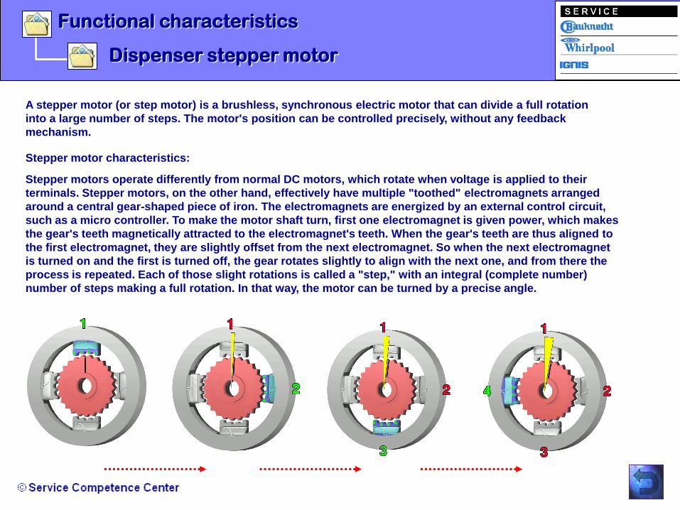
Functional characteristics
Dispenser stepper motor
A stepper motor (or step motor) is a brushless, synchronous electric motor that can divide a full rotation
into a large number of steps. The motor's position can be controlled precisely, without any feedback
mechanism.
Stepper motors operate differently from normal DC motors, which rotate when voltage is applied to their
terminals. Stepper motors, on the other hand, effectively have multiple "toothed" electromagnets arranged
around a central gear-shaped piece of iron. The electromagnets are energized by an external control circuit,
such as a micro controller. To make the motor shaft turn, first one electromagnet is given power, which makes
the gear's teeth magnetically attracted to the electromagnet's teeth. When the gear's teeth are thus aligned to
the first electromagnet, they are slightly offset from the next electromagnet. So when the next electromagnet
is turned on and the first is turned off, the gear rotates slightly to align with the next one, and from there the
process is repeated. Each of those slight rotations is called a "step," with an integral (complete number)
number of steps making a full rotation. In that way, the motor can be turned by a precise angle.
Stepper motor characteristics:

Functional characteristics
Dispenser heater
According to product model, one or two heater can be
attached to the User Interface board.
Heaters state will be set according to what communicated
by the Main Control board (User Interface board is not
provided with EEPROM so the heaters state will be stored
by Main Control board in case of a main power failure and
communicate when power is restored).
The state of the heaters can be toggled between on or off
pressing the virtual button 2.
No heaters state feedback is foreseen.
Heaters must always be turned off when other loads are
turned on (dispenser light and/or step motor) and during
the start up procedure, i.e. the heaters will be turned on
after 10 seconds and anyway after the initial start up of the
stepper motor has finished.
Heater default state will be set to ON when the system
start.

Functional characteristics
Dispenser paddles
According to product model (with dispenser or not) one or two paddles (mechanical or electronic) can be
attached to the User Interface board. These paddles will act as extra buttons.
Their state has to be communicate to the Main Control board through the dedicated data foreseen in the
communication protocol. When the "child lock" function is active even these paddle are locked.

Functional characteristics
Service Competence Center
Sankyo IDI / Biruni 7-segment UI / Victoria 2010

Evaporator Defrost Cycle
Evaporator Defrost Cycle
The defrost cycle starts when :
- The compressor runs ( effective running time ) for at least 8 hours
- A door was opened since the last defrost cycle
- The appliance is plugged in
- 50 hours passed since the last defrost cycle
Both doors are CLOSED until the time of 50hrs. -
Functional characteristics

Evaporator Defrost Cycle
Termination of the evaporator defrost cycle :
1. Standard function switches OFF
2. Freezer over temperature alarm is OFF
3. Compressor and both fans(compressor + evaporator) switches OFF
4. The air-baffle/damper switches into the CLOSE position
5. The heater starts to heat the evaporator with the following timing :
6. The evaporator bimetal thermostat reaches the opening temperature(+7°C C)
5 minutes ON 1 minute OFF 3 minutes ON 1 minute OFF and so on until point 6. takes effect
R-134a
Functional characteristics

Evaporator Defrost Cycle
7. The heater switches OFF immediately
8. The compressor switches ON after a elapsed time of 7 minutes
9. The condenser fan switches ON with a time delay of 1 minute after the compressor start
10. The damper and evaporator fan switches on with a time delay of 3 minutes after the
compressor start
11. The defrost process before will be restored
R-134a
Functional characteristics

- Disassembling Long Door Handle
- Disassembling 3D Multiflow
- Disassembling Flow Channel
- Disassembling User Interface with I&W
- Disassembling Ice Crusher Motor IDI 2
- Disassembling Sankyo IDI Ice-Maker
- Disassembling Ice Maker Water Tube
Repair Guide Line

Repair Guide Line
Disassembling Long Door Handle
Step 1: Remove the both screws on
the top of the handle.
Step 2: Lift up the plastic support of the handle and pull
forward the handle with the support.
Step 3: Now you have the access to
the main plastic support on the
door.

Repair Guide Line
Disassembling 3D Multiflow
Step 3: Disconect the plug of the
lamp and air-diffuser.
Step 1: Remove all three
transparent cover of
the 3D multiflow.
1
2
3
Step 2: Remove the rear fixation
screw of the multiflow and pull
forward the multiflow housing.

Repair Guide Line
Disassembling flow channel
1. Step: Remove all shelf‟s 3. Step: after the hook is released, lift
up the complete milky cover to remove
it. See the fixation hooks below.
2. Step: Lift up the hook
below the transparent air
channel cover as shown.

Repair Guide Line
Disassembling User Interface with I&W
Step 1: Remove the water
dispenser grid and unscrew the
both fixation screws.
Step 2: Unclip the dispenser front
panel (pull it to the front).

Repair Guide Line
Disassembling User Interface with I&W
Step 3: Disconnect all connectors
on the User Interface board.
Step 4: Remove the outlet of the
dispenser by pulling backwards.

Repair Guide Line
Disassembling User Interface with I&W
Step 5 : Unscrew the both fixation
screws of the dispenser support
and lose the both fixation kooks to
remove the dispenser assy.

Repair Guide Line
Disassembling User Interface with I&W
Step 6 : Unscrew the four screws of
the dispenser frame and unclip the
fixation kooks of it by starting from
one side to the other.

Repair Guide Line
Disassembling Ice Crusher Motor IDI 2
Step 1 : Remove the ice bin
container to get the access to
the top cover screws of the ice
crusher motor. Remove the four
screws and after the top cover.

Repair Guide Line
Disassembling Ice Crusher Motor IDI
Step 2 : Pull out the ice motor shaft.
Step 3 : Unscrew the two fixation
screws of the ice motor.

Repair Guide Line
Disassembling Ice Crusher Motor IDI
The picture shows you the rear view
of the top cover with the coupler ring.
Step 4 : Bring the ice motor out of the
niche and unclip the connector of it.

Disassembling Sankyo IDI ice-maker
Repair Guide Line
Step 1 : Push up the cover of the ice-maker and remove it.
Step 2 : Unscrew the both screws below the ice-maker.
Step 3 : Slide the ice-maker to the left side to release it.

Repair Guide Line
Step 5 : Bend forwards the ice-maker support, pull out the
wiring harness with the connector and disconnect it.
Step 4 : Unscrew the top right screw.
Disassembling Sankyo IDI ice-maker

Disassembling ice-maker water tube
Repair Guide Line
Step 6 : Unscrew the plinth (2 screws) and remove it.
Then disconnect the blue coloured tube from the
connector.
Step 7 : Remove the dispenser grid and unscrew the both
screws from the dispenser housing and pull it to
the front to release it.

Repair Guide Line
Step 8 : Disconnect all connectors
from the User Interface board.
Step 9 : Pull out the blue water tube (base
to dispenser unit).
Disassembling ice-maker water tube

Repair Guide Line
Step 10 : Remove the top plastic cover of ice maker.
Step 11 : Pull out the black rubber water channel from the
support.
Disassembling ice-maker water tube
- Board failure code description
- Board self test
- Alarm summery
- Failure codes summery
- Activation of the “Built-In” Test routine
- “Built-In” Test Operations and Codes Summery
- “Built-In” Test Error Codes Summery
- Filter reset after “Built-In” test sequence
- Documents: Manuals, NTC value table, SB‟s.
Troubleshooting

Board failure code description
Troubleshooting
CODE TYPE DESCRIPTION
UU Compatibility failure User Interface board does not recognize the code sent by Main
Control board.
LF Board failure User Interface Board did not pass the factory test.
Between both boards (Main Board and User Interface) there will be performed a
compatibility check (communication between the boards). If the Main Board receive a not
recognized code (not specified code), the freezer compartments display show the listed
failure code and no other operations will be accepted, because in case of failure all the loads
will be turned OFF.

Board self test
Troubleshooting
The User Interface Board turns ON all LEDs for 3 seconds after each plug-in.
This allow a visual verification that all the LEDs are properly working.
The User Interface board itself can not recognize any failure at this stage.
During this time no operations will be allowed. (e.g. button pressure, function engagements)

Troubleshooting
Alarm summery
Type Buzzer BLINKING ICON RESET
Freezer door alarm Yes (mute after 10 min) Freezer door icon Reset button
(Stop the buzzer)
Refrigerator door alarm Yes (mute after 10 min) Refrigerator door icon Reset button
(Stop the buzzer)
Air filter alarm No Air filter icon Reset button for 3 s.
(reset alarm)
Buzzer sound one time.
Water filter alarm No Water filter icon Reset button for 3 s.
(reset alarm)
Buzzer sound one time.
Over temperature alarm Yes (mute after 10 min) Alarm icon Reset button
(reset alarm and stop buzzer)
Long black out alarm Yes (mute after 10 min) Long black out alarm Reset button
(reset alarm and stop buzzer)
Failure (any) Yes (mute after 10 min) Alarm icon Reset button
(stop the buzzer)

Troubleshooting
Failure codes summery
COMPARTMENT DISPLAY DISPLAY CODE DESCRIPTION
Freezer display "U U" Wrong User Interface board
Freezer display "S F" Freezer sensor
Freezer display "H F" Ice maker SANKYO sensor
Refrigerator display "F" Refrigerator sensor
Refrigerator display "d" Damper unreliable
Refrigerator display "F" Refrigerator compartment
Freezer display "C F" Communication failure
Freezer display "LF" Production test not passed

Troubleshooting
Activation of the “Built-In” Test Routine
The freezer display
indicates the process
(e.g. „04“ means - Check
evaporator fan)
The fridge display
indicates the
failure code.
Example : „0“ is
standing for
everything is ok!
All the error codes will be displayed on the fridge display. Every check have the related error code,
that shall be the same as the sequence number foreseen during the test.
If 2 or more error codes have been recognized, these codes shall be displayed on the fridge display
in a rolling way. Each code shall persist about 1 seconds till the „Built-In“ test will be stopped.
!
For all Side by Side appliance range 2008 is the same Test routine for the main board and user
interface like last year available. The Built-In test allows the technician to check important
components which are listed in the following tables.

Step 1: If the appliance was plugged in for longer than 15 minutes, disconnect it from the
power socket, wait 40 seconds and plug it in again.
Step 2: Wait till the User Interface finish the bootstrap ( only LCD version ).
Step 3: Open the freezer door
Step 4: Press the freezer light switch 3 times within 10 seconds.
Step 5: The test should be activated and on the freezer display you can see the code „00“
For de-activation of the test procedure, disconnect the appliance from the power or repeat the step 4.
Note: the User Interface will be able to switch ON/OFF the Dispenser Lamp and to drive
the Ice-Motor in Ice-Cube Mode.
Troubleshooting
Activation of the “Built-In” Test Routine
To enter in the test routine, follow the described steps below :

Troubleshooting
“Built-In” Test Operations and Codes Summery
TYPE OF TEST
CORE BOARD OPERATION)
CHECKING
CODE
NOTE
(USER INTERFACE OPERATION)
Check evaporator de-frost heater 07 Displayed on 2 digit Freezer display
Check fridge probe 06 Displayed on 2 digit Freezer display
Check freezer probe 05 Displayed on 2 digit Freezer display
Check evaporator fan 04 Displayed on 2 digit Freezer display
Check compressor fan 03 Displayed on 2 digit Freezer display
Check damper/air baffle and relay
K008
02 Displayed on 2 digit Freezer display alternatively to the
code “00“
Check water valve 01 Displayed on 2 digit Freezer display alternatively to the
code “00“
Check Ice valve
09 Displayed on 2 digit Freezer display alternatively to the
code “00
Ice-Maker Sankyo initialization
without Ice-Valve activation
12 Displayed on 2 digit Freezer display alternatively to the
code “00“
Default thermostatic operation 00 Displayed on 2 digit Freezer display

Troubleshooting
“Built-In” Test Error Codes Summery
ERROR TYPE ERROR CODE NOTE
Components (Relay Damper) 8 Displayed on 1 digit refrigerator display
Evaporator De-Frost heater 7 Displayed on 1 digit refrigerator display
Fridge probe 6 Displayed on 1 digit refrigerator display
Freezer probe 5 Displayed on 1 digit refrigerator display
Evaporator fan 4 Displayed on 1 digit refrigerator display
Compressor fan 3 Displayed on 1 digit refrigerator display
Damper 2 Displayed on 1 digit refrigerator display
Water valve dispenser 1 Displayed on 1 digit refrigerator display
Ice valve 9 Displayed on 1 digit refrigerator display
Ice Maker Sankyo H Displayed on 1 digit refrigerator display

Troubleshooting
Filter reset after Built-In test sequence
Water Filter Indicator Factory / Service reset:
Press 4 times consecutively (within 10 sec) the water valve shaft switch.
The symbol “F” on the Refrigerator display will be shown in order to confirm the operation.
If a alarm code alarm is being showing, the symbol “F” will cycle together with them.
Antibacterial Filter Indicator Factory/Service reset:
Press 4 times consecutively (within 10 sec) the refrigerator compartment door switch.
The symbol “A” on the Freezer display shall be shown in order to confirm the operation.
If a alarm code is being showing, the symbol “F” will cycle together with them.
At the end of the Built-In Test is and all was OK, it will be displayed the code 00 till the
Built-In Test is completed.
At this time it will be possible to reset to „0“ the Water Filter Indication and / or the
Antibacterial Filter Indication in the following way:
Troubleshooting
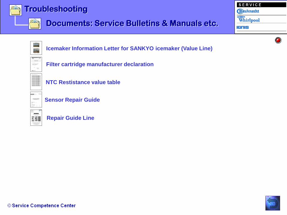
Documents: Service Bulletins & Manuals etc.
Icemaker Information Letter for SANKYO icemaker (Value Line)
Filter cartridge manufacturer declaration
NTC Restistance value table
Sensor Repair Guide
Repair Guide Line
Side by Side - Electronic Refrigerator
Production Cassinetta
The content of this repair guide line is based on knowledge status of November 2009. According to an ongoing development process any modifications are possible.
Repair guide Manual produced by Robert Zimmermann / Service Expert for Cooling & Freezing
ALL RIGHTS ON THIS MANUAL ARE STRICTLY RESERVED
REPRODUCTION OR ISSUE TO THIRD PARTIES IN ANY FORM WHATEVER IS NOT PERMITTED WITHOUT WRITTEN AUTHORITY FROM
THE PROPERTY OF WHIRLPOOL EUROPE © Whirlpool Europe - Service Competence Center; Industriestrasse 48;
D – 70565 Stuttgart; Germany
Whirlpool Europe Service Competence Center Robert Zimmermann Service Expert Cooling/Freezing In collaboration with: Marco Grandi & Diego Astori Side by Side platform Cassinetta
Repair Guide Line

Troubleshooting
Documents: Service Info
WSF 7656 W 8586 462 79100 (Whirlpool version)

- Main Board
- User Interface
- Stepper Motor Dispenser assy
- Dispenser paddle
- Dispenser LED
- Ice Motor IDI 2
Technical Data
- Lamps
- Defrost Heater
- Fan Motors
- Air Diffuser
- Ice Maker Sankyo IDI (Victoria)
- Water valve

Technical Data
Main Board
Power supply : Nominal voltage : 220 - 240 V AC
Operating voltage range : 185 - 264 V AC
Nominal frequency : 50 Hz +/- 2%
Connector pin assignment see next slide

Technical Data
Main Board
Technical Data
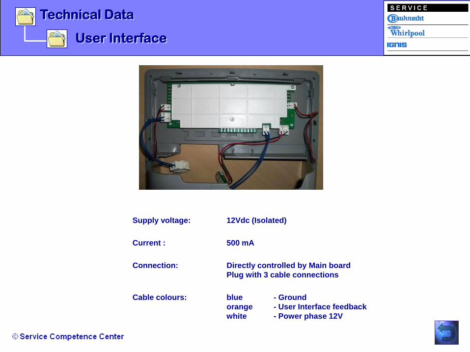
User Interface
Supply voltage: 12Vdc (Isolated)
Current : 500 mA
Connection: Directly controlled by Main board
Plug with 3 cable connections
Cable colours: blue - Ground
orange - User Interface feedback
white - Power phase 12V

Technical Data
Stepper Motor Dispenser assy
Supply voltage : 14 V DC; +/-5%
DC resisistance: 50 Ohm; +/-7%
Current : 0.28 +/-0.2A / Phase (at 14V DC)
Number of Phases : 4 Phases
Exitation : 2 Phases
Step Angle : 5° (at rotor)
PULL-OUT Torque : 0.2 Nm MIN, 0.3 Nm MAX

Technical Data
Stepper Motor Dispenser assy

Technical Data
Dispenser paddle
Switch : TS-12M-AHM-B-RS
Rating; 12V DC, 50mA

Technical Data
Dispenser LED
Supply voltage ( nominal ) : 14 V DC +/- 5%

Technical Data
Ice Motor IDI 2
Supply voltage ( nominal ) : 220 / 240V DC
Rated Torque : 11,3N.m. @ 0,3 AMPS
RPM : 15 +/- 15%

Lamps
Supply voltage ( nominal ) : 230 V AC; 50 Hz
Power dissipation : 40 W
Technical Data
Fridge & Freezer compartment :

Defrost Heater R134a
Supply voltage ( nominal ) : 230 V AC; 50 Hz
Power dissipation : 614W
AC resistance : 82-96 Ohm
Technical Data
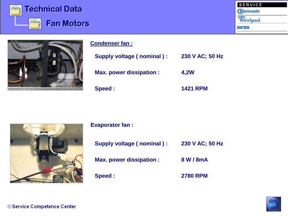
Fan Motors
Condenser fan :
Supply voltage ( nominal ) : 230 V AC; 50 Hz
Max. power dissipation : 4,2W
Speed : 1421 RPM
Technical Data
Evaporator fan :
Supply voltage ( nominal ) : 230 V AC; 50 Hz
Max. power dissipation : 8 W / 8mA
Speed : 2780 RPM

Air diffuser
Supply voltage ( nominal ) : 230 V AC; 50/60 Hz
Max. power dissipation : 0.7 W
Motor speed : 0.868 RPM
Time Chart A : 34.6 sec.
Time Chart B : 69.1 sec.
Technical Data

Technical Data
Ice-Maker Sankyo IDI 2
Supply voltage ( nominal ) : 12V DC
Motor power dissipation : 5 W
Ice production per day : max. 0,8 kg (with activated
fast freezing function under test / lab
condition)
Note: When the plus pole is connected with terminal 8
and the minus pole is connected with terminal 7, the
tray will rotate.
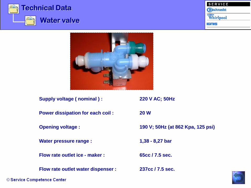
Water valve
Supply voltage ( nominal ) : 220 V AC; 50Hz
Power dissipation for each coil : 20 W
Opening voltage : 190 V; 50Hz (at 862 Kpa, 125 psi)
Water pressure range : 1,38 - 8,27 bar
Flow rate outlet ice - maker : 65cc / 7.5 sec.
Flow rate outlet water dispenser : 237cc / 7.5 sec.
Technical Data