siae microelettronica alc user manual - mn00142e-007
DESCRIPTION
SIAE User ManualTRANSCRIPT

User manual
Volume 1/1
MN.00142.E – 007
PDH radio systems
Compact version
AL

The information contained in this handbook is subject to change without notice.
Property of Siae Microelettronica S.p.A. All rights reserved according to the law and according to the international regula-tions. No part of this document may be reproduced or transmitted in any form or by any means, electronic or mechanical,without written permission from Siae Microelettronica S.p.A.
Unless otherwise specified, reference to a Company, name, data and address produced on the screen displayed is purelyindicative aiming at illustrating the use of the product.
Microsoft, MS–DOS, Windows, Windows NT and Windows 95 are trademarks of Microsoft Corporation.
Hewlett Packard, HP, HP OpenView Windows, Vectra and HP–UX are Hewlett Packard Company registered trademarks.
OSF Motif is an Open Software Foundation registered trademark.
UNIX is a Unix Systems Laboratories registered trademark.
INGRES is a Computer Associates registered trademark.
Other products cited here in are constructor registered trademarks.

Via Michelangelo Buonarroti, 21 – 20093 Cologno Monzese, Milano – Italy
Tel. (+39) 02 27325.1 – Fax (+39) 02 25301505 – e–mail [email protected]


AL (Compact version) – MN.00142.E – 007 I
ÎÎÎÎÎÎÎÎÎÎÎÎÎÎÎÎÎÎÎÎÎÎÎÎÎÎÎÎÎÎ
Contents
Section 1. . . . . . . . . . . . . . . . . . . . . . . . . . . . . . . . . . . . . . . . . . . . . . . . User guide 1. . . . . . . . . . . . . . . . . . . . . . . . . . . . . . . . . . . . . . . . . . . . .
1. DECLARATION OF CONFORMITY 3. . . . . . . . . . . . . . . . . . . . . . . . . .
2. FIRST AID FOR ELECTRICAL SHOCK AND SAFETY RULES 5. .
2.1 FIRST AID FOR ELECTRICAL SHOCK 5. . . . . . . . . . . . . . . . . . . . . . 2.1.1 Artificial respiration 5. . . . . . . . . . . . . . . . . . . . . . . . . . . 2.1.2 Treatment of burns 5. . . . . . . . . . . . . . . . . . . . . . . . . . .
2.2 SAFETY RULES 7. . . . . . . . . . . . . . . . . . . . . . . . . . . . . . . . . . . . . . . . . .
3. PURPOSE AND STRUCTURE OF THE MANUAL 9. . . . . . . . . . . . .
3.1 PURPOSE OF THE MANUAL 9. . . . . . . . . . . . . . . . . . . . . . . . . . . . . . .
3.2 AUDIENCE BASIC KNOWLEDGE 9. . . . . . . . . . . . . . . . . . . . . . . . . . .
3.3 STRUCTURE OF THE MANUAL 10. . . . . . . . . . . . . . . . . . . . . . . . . . . .
Section 13. . . . . . . . . . . . . . . . . . . . . . . . . . . . . . . . . . . . . . . . . . . . . . . . Descriptions and specification 13. . . . . . . . . . . . . . . . . . . . . . . . . .
4. ABBREVIATION LIST 15. . . . . . . . . . . . . . . . . . . . . . . . . . . . . . . . . . . . . .
4.1 LIST OF ABBREVIATIONS 15. . . . . . . . . . . . . . . . . . . . . . . . . . . . . . . . .

Contents
AL (Compact version) – MN.00142.E – 007II
5. SYSTEM PRESENTATION 17. . . . . . . . . . . . . . . . . . . . . . . . . . . . . . . . . .
5.1 RADIO SYSTEM OVERVIEW 17. . . . . . . . . . . . . . . . . . . . . . . . . . . . . . . 5.1.1 General 17. . . . . . . . . . . . . . . . . . . . . . . . . . . . . . . . . . . . .
5.2 COMPLIANCE WITH INTERNATIONAL STANDARDS 17. . . . . . . . .
5.3 APPLICATIONS 18. . . . . . . . . . . . . . . . . . . . . . . . . . . . . . . . . . . . . . . . . . .
5.4 SYSTEM ARCHITECTURE 18. . . . . . . . . . . . . . . . . . . . . . . . . . . . . . . . . 5.4.1 IDU 18. . . . . . . . . . . . . . . . . . . . . . . . . . . . . . . . . . . . . . . . 5.4.2 ODU 19. . . . . . . . . . . . . . . . . . . . . . . . . . . . . . . . . . . . . . .
5.5 MANAGEMENT SYSTEMS 19. . . . . . . . . . . . . . . . . . . . . . . . . . . . . . . . . 5.5.1 Management ports 19. . . . . . . . . . . . . . . . . . . . . . . . . . . 5.5.2 Protocols 19. . . . . . . . . . . . . . . . . . . . . . . . . . . . . . . . . . .
6. EQUIPMENT TECHNICAL SPECIFICATIONS 23. . . . . . . . . . . . . . . . .
6.1 TECHNICAL SPECIFICATION 23. . . . . . . . . . . . . . . . . . . . . . . . . . . . . .
7. CHARACTERISTICS OF THE INDOOR UNIT 33. . . . . . . . . . . . . . . . .
7.1 GENERAL 33. . . . . . . . . . . . . . . . . . . . . . . . . . . . . . . . . . . . . . . . . . . . . . . .
7.2 TRAFFIC INTERFACE 33. . . . . . . . . . . . . . . . . . . . . . . . . . . . . . . . . . . . . 7.2.1 2 Mbit/s interface 33. . . . . . . . . . . . . . . . . . . . . . . . . . . . . 7.2.2 Ethernet interface (option V12252) 34. . . . . . . . . . . . .
7.3 SERVICE CHANNEL INTERFACE 34. . . . . . . . . . . . . . . . . . . . . . . . . . . 7.3.1 V.28 low speed synchronous/asynchronous data 34. 7.3.2 Alarm interface 35. . . . . . . . . . . . . . . . . . . . . . . . . . . . . . 7.3.3 64 kbit/s contra–directional interface V.11 (optional) 357.3.4 Network Management Interface 35. . . . . . . . . . . . . . . .
7.4 MODULATOR/DEMODULATOR 36. . . . . . . . . . . . . . . . . . . . . . . . . . . . .
7.5 CABLE INTERFACE 36. . . . . . . . . . . . . . . . . . . . . . . . . . . . . . . . . . . . . . .
7.6 AVAILABLE LOOPS 37. . . . . . . . . . . . . . . . . . . . . . . . . . . . . . . . . . . . . . .
8. DESCRIPTION OF THE INDOOR UNIT – PDH INTERFACES 39. . .
8.1 1+0/1+1 IDU VERSIONS 39. . . . . . . . . . . . . . . . . . . . . . . . . . . . . . . . . . . 8.1.1 Line interface 39. . . . . . . . . . . . . . . . . . . . . . . . . . . . . . . .

Inhaltsverzeichnis
AL (Compact version) – MN.00142.E – 007 III
8.1.2 Radio interface 41. . . . . . . . . . . . . . . . . . . . . . . . . . . . . . 8.1.3 Equipment controller 42. . . . . . . . . . . . . . . . . . . . . . . . . .
8.2 IDU LOOPS 43. . . . . . . . . . . . . . . . . . . . . . . . . . . . . . . . . . . . . . . . . . . . . . 8.2.1 Tributary loop 44. . . . . . . . . . . . . . . . . . . . . . . . . . . . . . . . 8.2.2 Baseband unit loop 44. . . . . . . . . . . . . . . . . . . . . . . . . . . 8.2.3 IDU loop 44. . . . . . . . . . . . . . . . . . . . . . . . . . . . . . . . . . . .
9. DESCRIPTION OF THE INDOOR UNIT – ETHERNET INTERFACES 55. . . . . . . . . . . . . . . . . . . . . . . . . . . . . . . . . . . . . . . . . . . . .
9.1 TREATMENT OF ETHERNET SIGNALS 55. . . . . . . . . . . . . . . . . . . . . 9.1.1 2 Mbit/s tributaries 56. . . . . . . . . . . . . . . . . . . . . . . . . . . 9.1.2 Electrical Ethernet interface 56. . . . . . . . . . . . . . . . . . . 9.1.3 Front panel LEDs of Ethernet ports 57. . . . . . . . . . . . . 9.1.4 Bridge/switch function 57. . . . . . . . . . . . . . . . . . . . . . . . 9.1.5 Ethernet Full Duplex function 58. . . . . . . . . . . . . . . . . . 9.1.6 Link Loss Forwarding 59. . . . . . . . . . . . . . . . . . . . . . . . . 9.1.7 MDI/MDIX cross–over 59. . . . . . . . . . . . . . . . . . . . . . . . 9.1.8 VLAN functionality 59. . . . . . . . . . . . . . . . . . . . . . . . . . . 9.1.9 Switch organized by port 59. . . . . . . . . . . . . . . . . . . . . . 9.1.10 Switch organized by VLAN ID 60. . . . . . . . . . . . . . . . . . 9.1.11 Layer 2, Priority function, QoS, 802.1p 61. . . . . . . . . .
10. CHARACTERISTICS OF THE OUTDOOR UNIT 67. . . . . . . . . . . . . . .
10.1 GENERAL 67. . . . . . . . . . . . . . . . . . . . . . . . . . . . . . . . . . . . . . . . . . . . . . . .
10.2 TECHNICAL SPECIFICATION 67. . . . . . . . . . . . . . . . . . . . . . . . . . . . . .
11. DESCRIPTION OF THE OUTDOOR UNIT 71. . . . . . . . . . . . . . . . . . . .
11.1 GENERAL 71. . . . . . . . . . . . . . . . . . . . . . . . . . . . . . . . . . . . . . . . . . . . . . . .
11.2 TRANSMIT SECTION 71. . . . . . . . . . . . . . . . . . . . . . . . . . . . . . . . . . . . .
11.3 RECEIVE SECTION 72. . . . . . . . . . . . . . . . . . . . . . . . . . . . . . . . . . . . . . .
11.4 CABLE INTERFACE 73. . . . . . . . . . . . . . . . . . . . . . . . . . . . . . . . . . . . . . .
11.5 ATPC OPERATION 73. . . . . . . . . . . . . . . . . . . . . . . . . . . . . . . . . . . . . . . .
11.6 1+1 Tx SYSTEM 74. . . . . . . . . . . . . . . . . . . . . . . . . . . . . . . . . . . . . . . . . .

Contents
AL (Compact version) – MN.00142.E – 007IV
11.7 POWER SUPPLY 75. . . . . . . . . . . . . . . . . . . . . . . . . . . . . . . . . . . . . . . . .
12. 24/48 VOLT DC/DC CONVERTER D52089 81. . . . . . . . . . . . . . . . . . .
12.1 GENERAL 81. . . . . . . . . . . . . . . . . . . . . . . . . . . . . . . . . . . . . . . . . . . . . . . .
12.2 ENVIRONMENTAL CONDITIONS 82. . . . . . . . . . . . . . . . . . . . . . . . . . .
12.3 ELECTRICAL CHARACTERISTICS 82. . . . . . . . . . . . . . . . . . . . . . . . .
Section 87. . . . . . . . . . . . . . . . . . . . . . . . . . . . . . . . . . . . . . . . . . . . . . . . Installation 87. . . . . . . . . . . . . . . . . . . . . . . . . . . . . . . . . . . . . . . . . . . .
13. INSTALLATION AND PROCEDURESFOR ENSURING ELECTROMAGNETICCOMPATIBILITY 89. . . . . . . . . . . . . . . . . . . . . . . . . . . . . . . . . . . . . . . . . . .
13.1 GENERAL 89. . . . . . . . . . . . . . . . . . . . . . . . . . . . . . . . . . . . . . . . . . . . . . . .
13.2 MECHANICAL INSTALLATION 89. . . . . . . . . . . . . . . . . . . . . . . . . . . . . . 13.2.1 IDU installation 89. . . . . . . . . . . . . . . . . . . . . . . . . . . . . .
13.3 ELECTRICAL WIRING 90. . . . . . . . . . . . . . . . . . . . . . . . . . . . . . . . . . . . .
13.4 GROUNDING CONNECTION 91. . . . . . . . . . . . . . . . . . . . . . . . . . . . . . .
14. USER CONNECTIONS 93. . . . . . . . . . . . . . . . . . . . . . . . . . . . . . . . . . . . .
14.1 CONNECTOR USE FOR 1+0/1+1 STANDARD VERSION 93. . . . . .
14.2 STANDARD VERSION CONNECTORS 94. . . . . . . . . . . . . . . . . . . . . .
15. INSTALLATION ONTO THE POLE OF THE ODU WITH SEPARATED ANTENNA 97. . . . . . . . . . . . . . . . . . . . . . . . . . . . . . . . . . . . . . . . . . . . . . . .
15.1 INSTALLATION KIT 97. . . . . . . . . . . . . . . . . . . . . . . . . . . . . . . . . . . . . . .
15.2 REQUIRED TOOLS FOR MOUNTING (NOT SUPPLIED) 98. . . . . .
15.3 INSTALLATION PROCEDURE 98. . . . . . . . . . . . . . . . . . . . . . . . . . . . . .
15.4 GROUNDING 100. . . . . . . . . . . . . . . . . . . . . . . . . . . . . . . . . . . . . . . . . . . . .

Inhaltsverzeichnis
AL (Compact version) – MN.00142.E – 007 V
16. INSTALLATION ONTO THE WALL OF THE ODU WITH SEPARATED ANTENNA 113. . . . . . . . . . . . . . . . . . . . . . . . . . . . . . . . . . . . . . . . . . . . . . . .
16.1 INSTALLATION KIT 113. . . . . . . . . . . . . . . . . . . . . . . . . . . . . . . . . . . . . . .
16.2 REQUIRED TOOLS FOR MOUNTING (NOT SUPPLIED) 114. . . . . .
16.3 INSTALLATION PROCEDURE 114. . . . . . . . . . . . . . . . . . . . . . . . . . . . . .
16.4 GROUNDING 116. . . . . . . . . . . . . . . . . . . . . . . . . . . . . . . . . . . . . . . . . . . . .
17. INSTALLATION ONTO THE POLE OF THE ODU WITH INTEGRATEDANTENNA (KIT V52191, V52192) 125. . . . . . . . . . . . . . . . . . . . . . . . . . .
17.1 FOREWORD 125. . . . . . . . . . . . . . . . . . . . . . . . . . . . . . . . . . . . . . . . . . . . .
17.2 INSTALLATION KIT 125. . . . . . . . . . . . . . . . . . . . . . . . . . . . . . . . . . . . . . .
17.3 REQUIRED TOOLS FOR MOUNTING (NOT SUPPLIED) 126. . . . . .
17.4 INSTALLATION PROCEDURE 126. . . . . . . . . . . . . . . . . . . . . . . . . . . . . . 17.4.1 Installation onto the pole of the support system and the
antenna 127. . . . . . . . . . . . . . . . . . . . . . . . . . . . . . . . . . . . . 17.4.2 Installation of ODU 127. . . . . . . . . . . . . . . . . . . . . . . . . . . 17.4.3 ODU installation 128. . . . . . . . . . . . . . . . . . . . . . . . . . . . .
17.5 ANTENNA AIMING 129. . . . . . . . . . . . . . . . . . . . . . . . . . . . . . . . . . . . . . . .
17.6 GROUNDING 129. . . . . . . . . . . . . . . . . . . . . . . . . . . . . . . . . . . . . . . . . . . . .
18. INSTALLATION ONTO THE POLE OF THE ODU WITH INTEGRATEDANTENNA (KIT V32307, V32308, V32309) 147. . . . . . . . . . . . . . . . . . .
18.1 FOREWORD 147. . . . . . . . . . . . . . . . . . . . . . . . . . . . . . . . . . . . . . . . . . . . .
18.2 INSTALLATION KIT 147. . . . . . . . . . . . . . . . . . . . . . . . . . . . . . . . . . . . . . .
18.3 REQUIRED TOOLS FOR MOUNTING (NOT SUPPLIED) 148. . . . . .
18.4 INSTALLATION PROCEDURE 149. . . . . . . . . . . . . . . . . . . . . . . . . . . . . .
18.5 1+0 MOUNTING PROCEDURES 149. . . . . . . . . . . . . . . . . . . . . . . . . . . . 18.5.1 Setting antenna polarization 149. . . . . . . . . . . . . . . . . . . 18.5.2 Installation of the centring ring on the antenna 150. . . 18.5.3 Installation of 1+0 ODU support 150. . . . . . . . . . . . . . . . 18.5.4 Installation onto the pole of the assembled structure 15018.5.5 Installation of ODU (on 1+0 support) 150. . . . . . . . . . . . 18.5.6 Antenna aiming 151. . . . . . . . . . . . . . . . . . . . . . . . . . . . . . 18.5.7 ODU grounding 151. . . . . . . . . . . . . . . . . . . . . . . . . . . . . .
18.6 1+1 MOUNTING PROCEDURES 151. . . . . . . . . . . . . . . . . . . . . . . . . . . .

Contents
AL (Compact version) – MN.00142.E – 007VI
18.6.1 Installation of Hybrid 151. . . . . . . . . . . . . . . . . . . . . . . . . . 18.6.2 Installation of ODUs (on hybrid for 1+1 version) 152. .
19. INSTALLATION ONTO THE POLE OF THE 4 GHz ODU WITH SEPARATED ANTENNA (KIT V32323) 163. . . . . . . . . . . . . . . . . . . . . . .
19.1 INSTALLATION KIT 163. . . . . . . . . . . . . . . . . . . . . . . . . . . . . . . . . . . . . . .
19.2 REQUIRED TOOLS FOR MOUNTING (NOT SUPPLIED) 163. . . . . . 19.3 INSTALLATION PROCEDURE 164. . . . . . . . . . . . . . . . . . . . . . . . . . . . . .
Section 169. . . . . . . . . . . . . . . . . . . . . . . . . . . . . . . . . . . . . . . . . . . . . . . . Line–up 169. . . . . . . . . . . . . . . . . . . . . . . . . . . . . . . . . . . . . . . . . . . . . . .
20. LINE–UP OF THE RADIO HOP 171. . . . . . . . . . . . . . . . . . . . . . . . . . . . . .
20.1 LINE–UP OF THE RADIO HOP 171. . . . . . . . . . . . . . . . . . . . . . . . . . . . . 20.1.1 Antenna alignment and received field measurement 17120.1.2 Network element configuration 172. . . . . . . . . . . . . . . . . 20.1.3 Radio checks 173. . . . . . . . . . . . . . . . . . . . . . . . . . . . . . . .
21. LINE–UP OF ETHERNET TRAFFIC (FOR IDU WITH V12252 ETHERNETMODULE ONLY) 175. . . . . . . . . . . . . . . . . . . . . . . . . . . . . . . . . . . . . . . . . . .
21.1 GENERAL 175. . . . . . . . . . . . . . . . . . . . . . . . . . . . . . . . . . . . . . . . . . . . . . . .
21.2 LOCAL LAN–1 PORT TO REMOTE LAN–1 PORT (TRANSPARENT CONNECTION LAN PER PORT) 175. . . . . . . . . . . . . . . . . . . . . . . . . . . .
21.3 LOCAL LAN–1 PORT TO REMOTE LAN–1 PORT (WITH VLANs) 18221.4 3 TO 1 PORT CONNECTIONS 186. . . . . . . . . . . . . . . . . . . . . . . . . . . . . . 21.5 3 TO 1 PORT CONNECTIONS, SETTINGS FOR UNTAGGED
TRAFFIC 186. . . . . . . . . . . . . . . . . . . . . . . . . . . . . . . . . . . . . . . . . . . . . . . . . 21.6 3 TO 1 PORT CONNECTIONS, SETTINGS FOR TAGGED AND
UNTAGGED TRAFFIC 190. . . . . . . . . . . . . . . . . . . . . . . . . . . . . . . . . . . . . 21.7 3 TO 1 CONNECTIONS: EXAMPLES OF PRIORITY
MANAGEMENT 192. . . . . . . . . . . . . . . . . . . . . . . . . . . . . . . . . . . . . . . . . . .
Section 197. . . . . . . . . . . . . . . . . . . . . . . . . . . . . . . . . . . . . . . . . . . . . . . . Maintenance 197. . . . . . . . . . . . . . . . . . . . . . . . . . . . . . . . . . . . . . . . . . .
22. PERIODICAL CHECKS 199. . . . . . . . . . . . . . . . . . . . . . . . . . . . . . . . . . . . .
22.1 GENERAL 199. . . . . . . . . . . . . . . . . . . . . . . . . . . . . . . . . . . . . . . . . . . . . . . .

Inhaltsverzeichnis
AL (Compact version) – MN.00142.E – 007 VII
22.2 CHECKS TO BE CARRIED OUT 199. . . . . . . . . . . . . . . . . . . . . . . . . . . .
23. TROUBLESHOOTING 201. . . . . . . . . . . . . . . . . . . . . . . . . . . . . . . . . . . . . .
23.1 GENERAL 201. . . . . . . . . . . . . . . . . . . . . . . . . . . . . . . . . . . . . . . . . . . . . . . .
23.2 TROUBLESHOOTING PROCEDURE 201. . . . . . . . . . . . . . . . . . . . . . . . 23.2.1 Loop facilities 202. . . . . . . . . . . . . . . . . . . . . . . . . . . . . . . . 23.2.2 Alarm messages processing 202. . . . . . . . . . . . . . . . . . .
24. EQUIPMENT CONFIGURATION UPLOAD/SAVE/DOWNLOAD.PARAMETER MODIFICATION AND CREATION OF VIRTUALCONFIGURATIONS. 205. . . . . . . . . . . . . . . . . . . . . . . . . . . . . . . . . . . . . . .
24.1 SCOPE 205. . . . . . . . . . . . . . . . . . . . . . . . . . . . . . . . . . . . . . . . . . . . . . . . . .
24.2 PROCEDURE 205. . . . . . . . . . . . . . . . . . . . . . . . . . . . . . . . . . . . . . . . . . . . 24.2.1 General equipment configuration 206. . . . . . . . . . . . . . . 24.2.2 Addresses and routing table 207. . . . . . . . . . . . . . . . . . . 24.2.3 Remote Element Table 208. . . . . . . . . . . . . . . . . . . . . . . .
25. BACK UP FULL EQUIPMENT CONFIGURATION WITHOUTPOSSIBILITY OF MODIFYING THE PARAMETERS 211. . . . . . . . . . .
25.1 SCOPE 211. . . . . . . . . . . . . . . . . . . . . . . . . . . . . . . . . . . . . . . . . . . . . . . . . .
25.2 CONFIGURATION UPLOAD 211. . . . . . . . . . . . . . . . . . . . . . . . . . . . . . . .
25.3 CONFIGURATION DOWNLOAD 212. . . . . . . . . . . . . . . . . . . . . . . . . . . .
Section 213. . . . . . . . . . . . . . . . . . . . . . . . . . . . . . . . . . . . . . . . . . . . . . . . Programming and supervision 213. . . . . . . . . . . . . . . . . . . . . . . . . .
26. PROGRAMMING AND SUPERVISION 215. . . . . . . . . . . . . . . . . . . . . . .
26.1 GENERAL 215. . . . . . . . . . . . . . . . . . . . . . . . . . . . . . . . . . . . . . . . . . . . . . . .
Section 217. . . . . . . . . . . . . . . . . . . . . . . . . . . . . . . . . . . . . . . . . . . . . . . . Composition 217. . . . . . . . . . . . . . . . . . . . . . . . . . . . . . . . . . . . . . . . . . .
27. COMPOSITION OF THE INDOOR UNIT 219. . . . . . . . . . . . . . . . . . . . . .
27.1 GENERAL 219. . . . . . . . . . . . . . . . . . . . . . . . . . . . . . . . . . . . . . . . . . . . . . . .

Contents
AL (Compact version) – MN.00142.E – 007VIII
27.2 IDU PART NUMBER 219. . . . . . . . . . . . . . . . . . . . . . . . . . . . . . . . . . . . . . .
28. COMPOSITION OF OUTDOOR UNIT 221. . . . . . . . . . . . . . . . . . . . . . . .
28.1 GENERAL 221. . . . . . . . . . . . . . . . . . . . . . . . . . . . . . . . . . . . . . . . . . . . . . . .

AL (Compact version) – MN.00142.E – 007 1
ÓÓÓÓÓÓÓÓÓÓÓÓÓÓÓÓÓÓÓÓÓÓÓÓÓÓÓÓÓÓÓÓÓÓÓÓÓÓÓÓÓÓÓÓÓÓÓÓÓÓÓÓÓÓÓÓÓÓÓÓÓÓÓÓÓÓÓÓÓÓÓÓÓÓÓÓÓÓÓÓÓÓÓÓÓÓÓÓÓÓÓÓÓÓÓÓÓÓÓÓÓÓÓÓÓÓÓÓÓÓÓÓÓÓÓÓÓÓÓÓÓÓÓÓÓÓÓÓÓÓÓÓ
1Section
User guide

1. TITOLO DEL CAPITOLOCM.89012.I
AL (Compact version) – MN.00142.E – 0072

AL (Compact version) – MN.00142.E – 007 3
1. DECLARATION OF CONFORMITY
SIAE Microelettronica S.p.A. declares that the products:
• Digital radio relay system AL7
• Digital radio relay system AL8
• Digital radio relay system AL11
• Digital radio relay system AL13
• Digital radio relay system AL15
• Digital radio relay system AL18
• Digital radio relay system AL23
• Digital radio relay system AL25
• Digital radio relay system AL28
• Digital radio relay system AL38
comply with the essential requirements of article 3 of the R&TTE Directive (1999/05/EC) andtherefore is marked CE.
The following standards apply:
• EN 60950 200 “Safety of information technology equipment”.
• EN 301 489–4 V.1.3.1 (2002–8): “Electromagnetic compatibility and radio spectrumMatters (ERM); Electromagnetic Compatibility (EMC) standard for radio equipmentand services; Part 4. Specific conditions for fixed radio links and ancillary equipmentand services”
• ETSI EN 301 751 V.1.1. (2002–12): “Fixed Radio Systems; Point–to point equipmentand antennas; generic harmonized standard for point–to–point digital fixed radiosystems and antennas covering the essential requirements under article 3.2 of the1999/5/EC Directive”.
ÎÎÎÎÎÎÎÎÎÎÎÎÎÎÎÎÎÎÎÎÎÎÎÎÎÎÎÎÎÎÎÎÎÎÎÎ
1

1. TITOLO DEL CAPITOLOCM.89012.I
AL (Compact version) – MN.00142.E – 0074

AL (Compact version) – MN.00142.E – 007 5
2. FIRST AID FOR ELECTRICALSHOCK AND SAFETY RULES
2.1 FIRST AID FOR ELECTRICAL SHOCK
Do not touch the patient with bare hands until the circuit has been opened. Open the circuitby switching off the line switches. If that is not possible protect yourself with dry material andfree the patient from the conductor.
2.1.1 Artificial respiration
It is important to start mouth resuscitation at once and to call a doctor immediately. suggestedprocedure for mouth to mouth resuscitation method is described in the Tab. 2.1.
2.1.2 Treatment of burns
This treatment should be used after the patient has regained consciousness. It can also beemployed while artificial respiration is being applied (in this case there should be at least twopersons present).
Warning
• Do not attempt to remove clothing from burnt sections
• Apply dry gauze on the burns
• Do not apply ointments or other oily substances.
ÓÓÓÓÓÓÓÓÓÓÓÓÓÓÓÓÓÓÓÓÓÓÓÓÓÓÓÓÓÓÓÓÓÓÓÓ
2

1. TITOLO DEL CAPITOLOCM.89012.I
AL (Compact version) – MN.00142.E – 0076
Tab. 2.1
Step Description Figure
1 Lay the patient on his back with his arms parallel to the body. If thepatient is laying on an inclined plane, make sure that his stomachis slightly lower than his chest. Open the patients mouth andcheck that there is no foreign matter in mouth (dentures, chewinggum, etc.).
2 Kneel beside the patient level with his head. Put an hand underthe patient’s head and one under his neck.
Lift the patient’s head and let it recline backwards as far aspossible.
3 Shift the hand from the patient’s neck to his chin and his mouth,the index along his jawbone, and keep the other fingers closed to-gether. While performing these operations take a good supply ofoxygen by taking deep breaths with your mouth open.
4 With your thumb between the patient’s chin and mouth keep hislips together and blow into his nasal cavities
5 While performing these operations observe if the patient’s chestrises. If not it is possible that his nose is blocked: in that case openthe patient’s mouth as much as possible by pressing on his chinwith your hand, place your lips around his mouth and blow into hisoral cavity. Observe if the patient’s chest heaves. This secondmethod can be used instead of the first even when the patient’snose is not obstructed, provided his nose is kept closed by pres-sing the nostrils together using the hand you were holding hishead with. The patient’s head must be kept sloping backwards asmuch as possible.
6 Start with ten rapid expirations, hence continue at a rate of twelve/fifteen expirations per minute. Go on like this until the patient hasregained conscious–ness, or until a doctor has ascertained hisdeath.

1. TITOLO DEL CAPITOLOCM.89012.I
CM.89012.I
AL (Compact version) – MN.00142.E – 007 7
2.2 SAFETY RULES
When the equipment units are provided with the plate, shown in Fig. 2.1, it means that theycontain components electrostatic charge sensitive.
Fig. 2.1
In order to prevent the units from being damaged while handling, it is advisable to wear anelasticised band (Fig. 2.2) around the wrist ground connected through coiled cord (Fig. 2.3).
Fig. 2.2
Elasticized
Ban
d
Fig. 2.3

1. TITOLO DEL CAPITOLOCM.89012.I
AL (Compact version) – MN.00142.E – 0078
The units showing the label, shown in Fig. 2.4, include laser diodes and the emitted power canbe dangerous for eyes; avoid exposure in the direction of optical signal emission.
Fig. 2.4
LASER

AL (Compact version) – MN.00142.E – 007 9
3. PURPOSE AND STRUCTURE OF THEMANUAL
3.1 PURPOSE OF THE MANUAL
The purpose of this manual consists in providing the user with information which allows tooperate and maintain the ALC radio family.
Warning: This manual does not include information relevant to the SCT/LCT managementprogram windows and relevant application. They will provided by the program itself as help–online.
3.2 AUDIENCE BASIC KNOWLEDGE
The following knowledge and skills are required to operate the equipment:
• a basic understanding of microwave transmission
• installation and maintenance experience on digital radio system
• a good knowledge of IP/OSI networks and routing policy.
ÓÓÓÓÓÓÓÓÓÓÓÓÓÓÓÓÓÓÓÓÓÓÓÓÓÓÓÓÓÓÓÓÓÓÓÓ
3

1. TITOLO DEL CAPITOLOCM.89012.I
AL (Compact version) – MN.00142.E – 00710
3.3 STRUCTURE OF THE MANUAL
The manual is subdivided into sections each of them developing a specific topic entitling thesection.
Each section consists of a set of chapters, enlarging the main subject master.
Section 1 – User Guide
It provides the information about the main safety rules and expounds the purpose and thestructure of the manual.
Section 2 – Description and specifications
It traces the broad line of equipment operation and lists the main technical characteristics of thewhole equipment and units it consists of.
List of abbreviation meaning is also supplied.
Section 3 – Installation
The mechanical installation procedures are herein set down as well as the user electricalconnections.
The content of the tool kit (if supplied) is also listed.
Section 4 – Line–Up
Line–up procedures are described as well as checks to be carried out for the equipment correctoperation. The list of the instruments to be used and their characteristics are also set down.
Section 5 – Maintenance
The routine maintenance actions are described as well as fault location procedures in order toidentify the faulty unit and to re–establish the operation after its replacement with a spare one.

1. TITOLO DEL CAPITOLOCM.89012.I
CM.89012.I
AL (Compact version) – MN.00142.E – 007 11
Section 6 – Programming and supervision
The ALC radio family is programmed and supervised using different software tools. Some ofthem are already available, some other will be available in the future.
This section lists the tools implemented and indicates if descriptions are already available.
Each description of software tools is supplied in a separated manual.
Section 7 – Composition
Position, part numbers of the components the equipment consist of, are shown in this section.

1. TITOLO DEL CAPITOLOCM.89012.I
AL (Compact version) – MN.00142.E – 00712

AL (Compact version) – MN.00142.E – 007 13
ÓÓÓÓÓÓÓÓÓÓÓÓÓÓÓÓÓÓÓÓÓÓÓÓÓÓÓÓÓÓÓÓÓÓÓÓÓÓÓÓÓÓÓÓÓÓÓÓÓÓÓÓÓÓÓÓÓÓÓÓÓÓÓÓÓÓÓÓÓÓÓÓÓÓÓÓÓÓÓÓÓÓÓÓÓÓÓÓÓÓÓÓÓÓÓÓÓÓÓÓÓÓÓÓÓÓÓÓÓÓÓÓÓÓÓÓÓÓÓÓÓÓÓÓÓÓÓÓÓÓÓÓ
2Section
Descriptions andspecification

1. TITOLO DEL CAPITOLOCM.89012.I
AL (Compact version) – MN.00142.E – 00714

AL (Compact version) – MN.00142.E – 007 15
4. ABBREVIATION LIST
4.1 LIST OF ABBREVIATIONS
– AF Assured Forwarding
– ALC Access Link Compact Version
– AIS Alarm Indication Signal
– ATPC Automaric Transmit Power Control
– BB Baseband
– BBER Background Block Error Radio
– BER Bit Error Rate
– DSCP Differentiated Service Code Point
– DSP Digital Signal Processing
– EMC/EMI Electromagnetic Compatibility/Electromagnetic Interference
– EOC Embedded Overhead Channel
– ERC european Radiocommunication Committee
– ESD Electrostatic Discharge
– FEC Forward Error Corrector
– FEM Fast Ethernet Module
– HDLC High Level Data Link Control
– IDU Indoor Unit
– IF Intermediate Frequency
– IpToS Type of Service IP
– LAN Local Area Network
– LAPS Link Access Procedure SDH
– LCT Local Craft Terminal
– LIM Line Interface Module
ÓÓÓÓÓÓÓÓÓÓÓÓÓÓÓÓÓÓÓÓÓÓÓÓÓÓÓÓÓÓÓÓÓÓÓÓ
4

1. TITOLO DEL CAPITOLOCM.89012.I
AL (Compact version) – MN.00142.E – 00716
– LLF Link Loss Forwarding
– LOF Loss Of Frame
– LOS Loss Of Signal
– MAC Media Access Control
– MDI Medium Dependent Interface
– MDIX Medium Dependent Interface Crossover
– MIB Management Information Base
– MMIC Monolitic Microwave Integrated Circuit
– MTBF Mean Time Between Failure
– NE Network Element
– ODU Outdoor Unit
– OSI Open System Interconnection
– PDH Plesiochronous Digital Hierarchy
– PPI Plesiochronous Physical Interface
– PPP Point to Point Protocol
– PTOS Priority Type Of Service
– RIM Radio Interface Module
– SCT Subnetwork Craft Terminal
– SNMP Simple Network Management Protocol
– TCP/IP Transmission Control Protocol/Internet Protocol
– TOS Type Of Service
– VID Virtual LAN Identifier
– VLAN Virtual LAN
– WFQ Wait Fair Queue
– Wayside Traffic Additional 2 Mbit/s Traffic

AL (Compact version) – MN.00142.E – 007 17
5. SYSTEM PRESENTATION
5.1 RADIO SYSTEM OVERVIEW
5.1.1 General
AL is SIAE’s PDH radio series for low–to–medium transmission capacities in frequency bandsfrom 7 to 38 GHz.
Different hardware versions offer a range of tributaries traffic from 2xE1 to 16xE1, with or withoutEthernet traffic, on 4 and 16QAM modulation, with capacity up to 64 Mbit/s.
Reduced cost, high reliability, compact size, light weight and full programmability are the keyfeatures of this radio series.
5.2 COMPLIANCE WITH INTERNATIONAL STANDARDS
The equipment complies with the following international standards:
• EN 301 489–4 for EMC
• ITU–R recommendations for all frequency bands
• EN 300 132–2 characteristics for power supply
• EN 300 019 environmental characteristics (Operation class 3.2 for IDU and class 4.1for ODU; storage: class 1.2; transport: class 2.3)
• EN 60950 for safety
ÓÓÓÓÓÓÓÓÓÓÓÓÓÓÓÓÓÓÓÓÓÓÓÓÓÓÓÓÓÓÓÓÓÓÓÓ
5
1. TITOLO DEL CAPITOLOCM.89012.I
AL (Compact version) – MN.00142.E – 00718
5.3 APPLICATIONS
AL main applications are:
• radio communication between GSM cells
• radio links for voice and data transmission
• spur routes for high capacity radio system
• emergency links
• Ethernet traffic in point to point communication
5.4 SYSTEM ARCHITECTURE
The AL radio equipment consist of two separate units:
• the indoor unit (IDU) that houses tributary interfaces, Ethernet ports modem andcontroller units
• the outdoor unit (ODU) that converts IF signals into RF signals and vice versa.
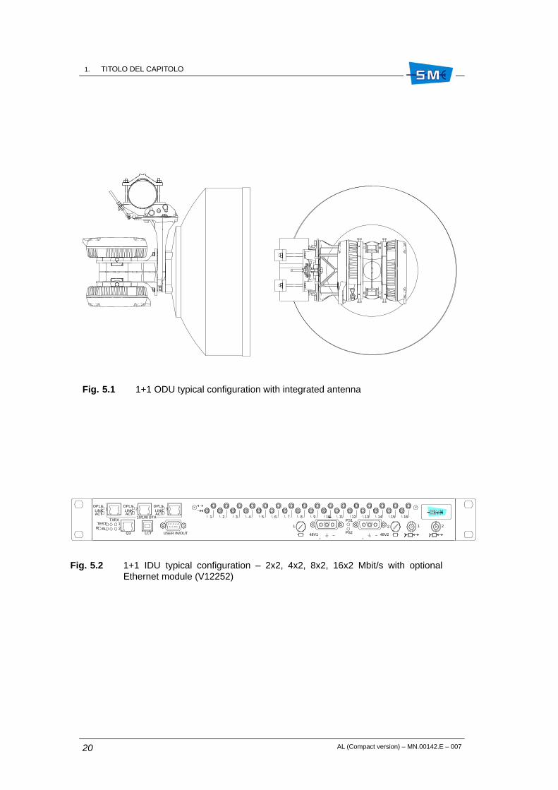
The two units are interconnected via coaxial cable. Fig. 5.1 and Fig. 5.2 show a typical IDU/ODUlayout whereas Fig. 5.3 and Fig. 5.4 show the radio block diagram in 1+0 and 1+1 configurationrespectively.
5.4.1 IDU
The IDU is available in the following hardware versions:
• 1 rack unit compact IDU, 1+0 configuration, 2/4/8xE1
• 1 rack unit compact IDU, 1+0 configuration, 2/4/8/16xE1
• 1 rack unit compact IDU, 1+1 configuration, 2/4/8xE1
• 1 rack unit compact IDU, 1+1 configuration, 2/4/8/16xE1
Ethernet module V12252 can be housed inside IDU, as option, for Ethernet traffic. CompactIDUs consist of a single circuit board plugged into a wired shelf.
Line interfaces house tributary connections and, through a multiplexing/demultiplexing and bitinsertion/extraction process, supply/receive the aggregate signal to/from themodulator/demodulator.
Line interfaces carry out the digital processing for the QAM modulator and, in 1+1 configuration,duplicate the main signals on the transmission side and perform the changeover on the receive

1. TITOLO DEL CAPITOLOCM.89012.I
CM.89012.I
AL (Compact version) – MN.00142.E – 007 19
side. Interfaces towards the ODU house the cable interface for bidirectional communicationbetween ODU and IDU, and implement the IF section of the mo–demodulator.
IDU power supply units process battery voltage and supply power to IDU and ODU circuits. Thecontroller section of the radio houses service channels interfaces, stores IDU firmware,interfaces SIAE management systems though dedicated supervision ports, and routes externaland internal alarms to relay contacts.
5.4.2 ODU
The ODU houses the interface towards the IDU on one side, and towards the antenna flangeon the other. The ODU shifts the incoming QAM–modulated carrier to RF frequency through adouble conversion. The opposite occurs at the receive side, when the IF–converted carrier issent to the IDU demodulator.
Antenna coupling in 1+1 systems is done through a balanced or unbalanced hybrid.
5.5 MANAGEMENT SYSTEMS
AL radio can be controlled locally and remotely via SIAE supervision software:
• SCT/LCT: a Windows–based management system for small networks (up to 100 NE)
• NMS5–LX: a Linux–based management system for small–to–medium networks (upto 750 NE)
• NMS5–UX: a Unix–based management system for large networks (up to 2500 NE)
These systems provide a friendly graphic interface complying with current standard use ofkeyboards, mouse and windows.
5.5.1 Management ports
AL radio terminals connect to the supervision network via the following communication ports:
• Ethernet 10BaseT Port
• USB port
5.5.2 Protocols
SNMP along with IP or OSI protocol stacks are used to manage AL operation.
1. TITOLO DEL CAPITOLOCM.89012.I
AL (Compact version) – MN.00142.E – 00720
Fig. 5.1 1+1 ODU typical configuration with integrated antenna
Fig. 5.2 1+1 IDU typical configuration – 2x2, 4x2, 8x2, 16x2 Mbit/s with optionalEthernet module (V12252)
10/100 BTX
321ACTLINK
DPLXDPLXLINKACTACT
LINKDPLX
21
RXTX
ALTEST
RPS2
PS1
2121
48V2
+ ––+
48V1Q3 LCT USER IN/OUT
1 2 3 4 5 6 7 8 9 10 11 12 13 14 15 16

1. TITOLO DEL CAPITOLOCM.89012.I
CM.89012.I
AL (Compact version) – MN.00142.E – 007 21
Fig. 5.3 1+1 equipment block diagram
Mai
n tr
affic
CA
BLE
INT
ER
F.
OD
U 1
CO
NT
RO
LLE
R
Ser
vice
s
CA
BLE
INT
ER
F.
OD
U 2
CO
NT
RO
LLE
R
Rad
io In
terf
ace
2
MA
IN
CO
NT
RO
LLE
R
IDU
CO
NT
RO
L
Co
ntr
olle
r U
nit
IDU
CA
BLE
CA
BLE
INT
ER
F.1
Tx1
Rx1
OD
U 1
SW
CO
NT
R.
Tx2
Rx2
OD
U 2
SW
CO
NT
R.
CA
BLE
MU
X
DE
MU
X
4 dB or
1.5/
7.5
dB
Mai
n tr
affic
CA
BLE
INT
ER
F.2
MO
D
DE
M
SC
T/L
CT
OD
U C
ON
TR
OL
ALA
RM
BI
DS
P
DS
P
IF IF
Lin
e In
terf
ace
BA
TT.
MO
D
DE
M
BA
TT.
DS
P
48 V
48 V
Ser
vice
s
MO
D
DE
M
DE
M
BE
IF IF
Rad
io In
terf
ace
1

1. TITOLO DEL CAPITOLOCM.89012.I
AL (Compact version) – MN.00142.E – 00722
Fig. 5.4 1+0 non expandable equipment block diagram
Mai
n tr
affic
CA
BLE
INT
ER
F.
OD
UC
ON
TR
OLL
ER
Ser
vice
s
MA
IN
CO
NT
RO
LLE
R
IDU
CO
NT
RO
L
CA
BLE
CA
BLE
INT
ER
F.1
Tx1
Rx1
OD
U
SW
CO
NT
R.
MU
X
DE
MU
XM
ain
traf
fic
MO
D
DE
M
SC
T/L
CT
OD
U C
ON
TR
OL
ALA
RM
BI
DS
P
DS
P
IF IF
BA
TT.
48 V
Ser
vice
s
MO
D
DE
M
BE
IDU

AL (Compact version) – MN.00142.E – 007 23
6. EQUIPMENT TECHNICALSPECIFICATIONS
6.1 TECHNICAL SPECIFICATION
•– 7.11 to 7.7 GHz
– 7.7 to 8.5 GHz
– 10.7 to 11.7 GHz
– 12.75 to 13.25 GHz
– 14.4 to 15.35 GHz
– 17.7 to 19.7 GHz
– 21.2 to 23.6 GHz
– 24.5 to 26.5 GHz
– 27.5 to 29.5 GHz
– 37 to 39.5 GHz
•– ITU–R Rec F.385
– ITU–R Rec F.386
– no ITU–R Rec. for PDH 11 GHz band
– ITU–R Rec F.497
– ITU–R Rec F.636
– ITU–R Rec F.595
– ERC/T/R 13–02 Annex A or ITU–R Rec F.637
– ERC/T/R 13–02 Annex B
– ERC/T/R 13–02 Annex C
– ITU–R Rec F.749
ÓÓÓÓÓÓÓÓÓÓÓÓÓÓÓÓÓÓÓÓÓÓÓÓÓÓÓÓÓÓÓÓÓÓÓÓ
6
Frequency range
7 GHz
8 GHz
11 GHz
13 GHz
15 GHz
18 GHz
23 GHz
25 GHz
28 GHz
38 GHz
RF channel arrangement
7 GHz
8 GHz
11 GHz
13 GHz
15 GHz
18 GHz
23 GHz
25 GHz
28 GHz
38 GHz

1. TITOLO DEL CAPITOLOCM.89012.I
AL (Compact version) – MN.00142.E – 00724
•– 245/196/168/161/154 MHz
– 311.32 MHz
– 530 MHz
– 266 MHz
– 420/728 MHz
– 1010 MHz
– 1008/1232 MHz
– 1008 MHz
– 1008 MHz
– 1260 MHz
•– see Tab. 6.1
Tab. 6.1 Signal capacity
Capacity (Mbit/s) Configuration Mechanical dimension
2x2/4x2/8x2 (max 16 Mbit/s) 1+0/1+1 1 unit
2x2/4x2/8x2/16x2 (max 32 Mbit/s) 1+0/1+1 1 unit
16x2 + Ethernet (max 32 Mbit/s) 1+0/1+1 1 unit
16x2 + Ethernet (max 64 Mbit/s) 1+0/1+1 1 unit
•
The following service channel and auxiliary capacity is available:
• 1+0/1+1 standard – 2x2, 4x2, 8x2, 16x2 Mbit/s version (1 standard unit)
One of the following service channels is available:
– 64 kbit/s V11 co/contradirectional interface
• 1+0 or 1+1 hot stand–by and 1 antenna, 1+1frequency diversity on 1 cross polar antenna ortwo separated antennas
• ± 5 ppm; ± 10 ppm ageing included
• according to ETSI EN 301 390
• 4QAM/16QAM
Go–return frequency
7 GHz
8 GHz
11 GHz
13 GHz
15 GHz
18 GHz
23 GHz
25 GHz
28 GHz
38 GHz
Transmission capacity
Up to 16x2 Mbit/s with or withoutEthernet traffic
Service channel capacity
Antenna configuration
Frequency accuracy
RF spurious emissions
Modulation

1. TITOLO DEL CAPITOLOCM.89012.I
CM.89012.I
AL (Compact version) – MN.00142.E – 007 25
Tab. 6.2 Modulation used according to bit rate and RF channel space
Modulat. type
Bit rate (Mbit/s)type
2x2 4x2 8x2 16x2 64
4QAM 3.5 MHz 7 MHz 14 MHz 28 MHz –
16QAM n.a. 3.5 MHz 7 MHz 14 MHz 28 MHz
• coherent
• refer to Tab. 6.3
• refer to Tab. 6.4 and Tab. 6.5
•
– version with balanced hybrid
– version with unbalanced hybrid
• 1x10–11
• –20 dBm
Tab. 6.3 Nominal output power �1 dB tolerance
Frequency Output power 4QAM Output power 16QAM
7 GHz +27 dBm +22 dBm
8 GHz +27 dBm +22 dBm
11 GHz +25 dBm +20 dBm
13 GHz +25 dBm +20 dBm
15 GHz standard +25 dBm +20 dBm
15 GHz LP +20 dBm –
18 GHz +20 dBm +15 dBm
23 GHz +20 dBm +15 dBm
25 GHz +20 dBm +15 dBm
28 GHZ +19 dBm +14 dBm
38 GHz +17 dBm +13 dBm
Demodulation
Output power at the antenna side,1+0 version
Receiver threshold at the antennaside 1+0 version
Additional losses both Tx and Rxsides, 1+1 version
4 dB ±0.5 dB
≤1.7 dB (branch1)/≤7 dB(branch 2)
Residual BER
Maximum input level for BER 10–3

1. TITOLO DEL CAPITOLOCM.89012.I
AL (Compact version) – MN.00142.E – 00726
Tab. 6.4 Guaranteed received threshold in 1+0 configuration
4QAM 16QAM
Freq. 2x2 4x2 2x2 4x2q
10–6 10–3 10–6 10–3 10–6 10–3 10–6 10–3
7 –91 dBm –93 dBm –88 dBm –90 dBm – – –84 dBm –86 dBm
8 –91 dBm –93 dBm –88 dBm –90 dBm – – –84 dBm –85 dBm
11 –90.5 dBm –92.5 dBm –87.5 dBm –89.5 dBm – – –83.5 dBm –85.5 dBm
13 –90.5 dBm –92.5 dBm –87.5 dBm –89.5 dBm –83.5 dBm –85.5 dBm
15 –90.5 dBm –92.5 dBm –87.5 dBm –89.5 dBm – – –83.5 dBm –85.5 dBm
18 –90 dBm –92 dBm –87 dBm –89 dBm – – –84 dBm –86 dBm
23 –90 dBm –92 dBm –87 dBm –89 dBm – – –83 dBm –85 dBm
25 –89.5 dBm –91.5 dBm –86.5 dBm –88.5 dBm – – –82.5 dBm –84.5 dBm
28 –89 dBm –91 dBm –86 dBm –88 dBm – – –82 dBm –84 dBm
38 –88 dBm –90 dBm –85 dBm –88 dBm – – –81 dBm –83 dBm
Tab. 6.5 Guaranteed received threshold in 1+0 configuration
4QAM 16QAM
Freq. 8x2 16x2 8x2 16x2q
10–6 10–3 10–6 10–3 10–6 10–3 10–6 10–3
7 –85 dBm –87 dBm –82 dBm –84 dBm –81 dBm –83 dBm –78 dBm –80 dBm
8 –85 dBm –87 dBm –82 dBm –84 dBm –81 dBm –83 dBm –78 dBm –80 dBm
11 –84.5 dBm –86.5 dBm –81.5 dBm –83.5 dBm –80.5 dBm –82.5 dBm –77.5 dBm –79.5 dBm
13 –84.5 dBm –86.5 dBm –81.5 dBm –83.5 dBm –80.5 dBm –82.5 dBm –77.5 dBm –79.5 dBm
15 –84.5 dBm –86.5 dBm –81.5 dBm –83.5 dBm –80.5 dBm –82.5 dBm –77.5 dBm –79.5 dBm
18 –84 dBm –86 dBm –81 dBm –83 dBm –80 dBm –82 dBm –77 dBm –79 dBm
23 –84 dBm –86 dBm –81 dBm –83 dBm –80 dBm –82 dBm –77 dBm –79 dBm
25 –83.5 dBm –85.5 dBm –80.5 dBm –82.5 dBm –79.5 dBm –81.5 dBm –76.5 dBm –78.5 dBm
28 –83 dBm –85 dBm –80 dBm –82 dBm –79 dBm –81 dBm –76 dBm –78 dBm
38 –82 dBm –84 dBm –80 dBm –81 dBm –78 dBm –80 dBm –75 dBm –77 dBm

1. TITOLO DEL CAPITOLOCM.89012.I
CM.89012.I
AL (Compact version) – MN.00142.E – 007 27
•– –40.8 to –57.6 Vdc
•
Fully equipped terminal with 370 m 1/4” IDU–ODU cable (refer to Tab. 6.6).
Tab. 6.6
Configuration
Guaranteed power consumption (IDU)
f�15 GHz–40.8 to –57.6 Vdc
Guaranteed power consumption (IDU)
f>15 GHz–40.8 to –57.6 Vdc
1+0 ≤32 W ≤25 W
1+1 ≤52 W ≤40 W
• (refer to Tab. 6.7)
Tab. 6.7
Configuration
Guaranteed power consumption (IDU)
f�15 GHz–40.8 to –57.6 Vdc
Guaranteed power consumption (IDU)
f >15 GHz–40.8 to –57.6 Vdc
1+0 ≤11 W ≤11 W
1+1 ≤12 W ≤12 W
• (refer to Tab. 6.8)
Tab. 6.8
Guaranteed consumptionf� 15 GHz –40,8Vdc
Guaranteed consumptionf> 15 GHz –40,8Vdc
≤ 0,79 A ≤ 0,62 A
• 3.15 A (M), 5x20 mm
•– –5° C to +45° C
– –33° C to +55° C
– –10° C to +55° C
– –40° C to +60° C
Power supply
Power supply voltage
Power consumption
IDU only power consumption
Power supply connector consumption
Fuse
Environmental conditions
Operational range for IDU
Operational range for ODU
Survival temperature rangefor IDUSurvival temperature rangefor ODU

1. TITOLO DEL CAPITOLOCM.89012.I
AL (Compact version) – MN.00142.E – 00728
– 95% at +35° C– weather proof according to IP65 environmental
class– Thermal resistance 0.5° C/W
Solar heat gain: not exceeding 5° C– ≤260 Km/h
•– refer to Tab. 6.9
Tab. 6.9 IDU/ODU dimensions
Width (mm) Height (mm) Depth (mm)
ODU 1+0 version 250 250 100
ODU 1+1 version 278 255 280
IDU 1+0/1+1 480 45 260
– refer to Tab. 6.10
Tab. 6.10 IDU/ODU weight
ODU 1+0 4.5 kg 1 1
ODU 1+1 13.3 kg 2 2
IDU 1+0/1+1 3.5/3.7 kg
Panning system 1+0/1+1 4.4 kg
– refer to typical Fig. 6.1, Fig. 6.2 and Fig. 6.3.
Fig. 6.1 IDU 1+0 standard (2x2/4x2 Mbit/s)
48V
+ –
Trib. 1–2–3–4
Trib. 5–6–7–8
PSLCTQ3 USER IN/OUT
RTEST
AL
Fig. 6.2 IDU 1+1 standard (2x2/4x2/8x2/16x2 Mbit/s)
2
1RXTX
AL
TESTR
USER IN/OUTQ3 LCT
PS2
PS1
Trib. 13–14–15–16Trib. 5–6–7–8
Trib. 9–10–11–12Trib. 1–2–3–4
2121
48V2
+ ––+
48V1
1. 7/8 GHz 1+0: 5.5 kg
2. 7/8 GHz 1+1: 15.3 kg
Operational humidity for IDUOperational humidity for ODU
Heat dissipation of ODU
Wind load
Mechanical characteristicsDimensions
Weight
Mechanical layout

1. TITOLO DEL CAPITOLOCM.89012.I
CM.89012.I
AL (Compact version) – MN.00142.E – 007 29
Fig. 6.3 IDU 1+1 (up to 16x2 Mbit/s coax. conn.) + Ethernet module
10/100 BTX
321ACTLINK
DPLXDPLXLINKACTACT
LINKDPLX
21
RXTX
ALTEST
RPS2
PS1
2121
48V2+ ––+
48V1Q3 LCT USER IN/OUT
1 2 3 4 5 6 7 8 9 10 11 12 13 14 15 16

1. TITOLO DEL CAPITOLOCM.89012.I
AL (Compact version) – MN.00142.E – 00730
Fig. 6.4 1+0 ODU with separated antenna (pole mounting)
Fig. 6.5 1+1 ODU with separated antenna

1. TITOLO DEL CAPITOLOCM.89012.I
CM.89012.I
AL (Compact version) – MN.00142.E – 007 31
Fig. 6.6 1+0 ODU with integral antenna (pole mounting)
Fig. 6.7 1+1 ODU with integral antenna (pole mounting)

1. TITOLO DEL CAPITOLOCM.89012.I
AL (Compact version) – MN.00142.E – 00732
Fig. 6.8 1+1 ODU with separated antenna (wall mounting)

AL (Compact version) – MN.00142.E – 007 33
7. CHARACTERISTICS OF THEINDOOR UNIT
7.1 GENERAL
The following IDU characteristics are guaranteed for the temperature range from –5° C to+45° C.
7.2 TRAFFIC INTERFACE
7.2.1 2 Mbit/s interface
Input side
• 2048 kbit/s ±50 ppm
• HDB3
• 75 Ohm or 120 Ohm
• 2.37 Vp/75 Ohm or 3 Vp/120 Ohm
• 12 dB from 57 kHz to 102 kHz18 dB from 102 kHz to 2048 kHz14 dB from 2048 kHz to 3072 kHz
• 6 dB according to √f trend
ÓÓÓÓÓÓÓÓÓÓÓÓÓÓÓÓÓÓÓÓÓÓÓÓÓÓÓÓÓÓÓÓÓÓÓÓ
7
Bit rate
Line code
Rated impedance
Rated level
Return loss
Max attenuation of the input cable

1. TITOLO DEL CAPITOLOCM.89012.I
AL (Compact version) – MN.00142.E – 00734
• see mask in Table 2, CCITT Rec. G.823
• see mask in Figure 1, CCITT Rec. G.742
• SUB–D, 25 pins
Output side
• 2048 kbit/s ±50 ppm
• 75 Ohm or 120 Ohm
• 2.37 Vp/75 Ohm or 3 Vp/120 Ohm
• in accordance with G.742/G.823
• see mask in Figure 15, CCITT Rec. G.703
• SUB–D, 25 pins
7.2.2 Ethernet interface (option V12252)
RJ45 interface
• Ethernet Twisted Pair 802.3 10BaseT/100BaseT
• RJ45
• direct with a CAT5 Twisted Pair
• TCP/IP or IPoverOSI
7.3 SERVICE CHANNEL INTERFACE
7.3.1 V.28 low speed synchronous/asynchronous data
• RS232
• CCITT Rec. V.28
• 9600 baud
• DTR, DSR, DCD
Accepted jitter
Transfer function
Connector type
Bit rate
Rated impedance
Rated level
Output jitter
Pulse shape
Connector type
LAN type
Connector
Connection to LAN
Protocol
Data interface
Electrical interface
Input speed
Control wires

1. TITOLO DEL CAPITOLOCM.89012.I
CM.89012.I
AL (Compact version) – MN.00142.E – 007 35
7.3.2 Alarm interface
User output
• normally open (NO) or normally closed (NC)
• 100 Mohm at 500 Vdc
• 0.5 Ohm
• 100 V
• 1A
User input
• 200 Ohm resist. (max) referred to ground
• 60 kOhm (min) referred to ground
7.3.3 64 kbit/s contra–directional interface V.11 (optional)
• ±100 ppm
• contra–directional
• clock and data on independent wires
• see Rec. CCITT V.11
7.3.4 Network Management Interface
RJ45 interface
• Ethernet Twisted Pair 802.3 10BaseT/100BaseT
• RJ45
• direct with a CAT5 Twisted Pair
• TCP/IP or IPoverOSI
Relay contacts
Open contacts Rmin
Closed contacts Rmax
Switching voltage Vmax
Switching current Imax
Equivalent circuit recognised as aclosed contact
Equivalent circuit recognised asan open contact
Tolerance
Equipment side
Coding
Electrical interface
LAN type
Connector
Connection to LAN
Protocol

1. TITOLO DEL CAPITOLOCM.89012.I
AL (Compact version) – MN.00142.E – 00736
LCT USB interface
• USB 1.1 version
• 1.5 Mbit/s
• PPP
RS232 interface (optional)
• V.28
• 9600, 19200, 38400, 57600
• PPP
7.4 MODULATOR/DEMODULATOR
•– 330 MHz
– 140 MHz
• 4QAM/16QAM
• from 4 Mbit/s to 34 Mbit/s depending on differentversions
• raised cosine (roll–off = 0.5)
• 5 taps
• 2.5 dB at 10–6
7.5 CABLE INTERFACE
• single coaxial cable for both Tx and Rx
• up to 370 m. with 1/4” cable type
• 50 Ohm
Electrical interface
Baud rate
Protocol
Electronic interface
Asynchronous baud rate
Protocol
Carrier modulating frequency
Tx side
Rx side
Type of modulation
Modulating signal
Spectrum shaping
Equalization
FEC coding gain
Interconnection with the ODU unit
Cable length
Rated impedance

1. TITOLO DEL CAPITOLOCM.89012.I
CM.89012.I
AL (Compact version) – MN.00142.E – 007 37
•– 330 MHz
– 140 MHz
– 388 kbit/s bidirectional
– IDU to ODU = 17.5 MHz/0 dBmODU to IDU = 5.5 MHz/0 dBm
– direct from battery voltage
7.6 AVAILABLE LOOPS
The following loop are available within the IDU:
• Tributary loop
• Baseband loop
• IDU loop
Signal running along the cable
Tx nominal frequency
Rx nominal frequency
Transceiver management signals
Carrier for transceiver man-agement signals
Remote power supply

1. TITOLO DEL CAPITOLOCM.89012.I
AL (Compact version) – MN.00142.E – 00738

AL (Compact version) – MN.00142.E – 007 39
8. DESCRIPTION OF THE INDOORUNIT – PDH INTERFACES
8.1 1+0/1+1 IDU VERSIONS
The following functional description covers the versions the IDU consists of as shown in chapter“Equipment technical specifications”.
The IDU is made up of a single motherboard that houses all the circuitry realizing the followingfunctionalities:
• Line interface
• Radio interface
• Equipment controller
• IDU loops
8.1.1 Line interface
The line interface performs the following operations:
• multiplexing process of the input tributaries
• generation of the aggregate frame by aggregating multiplexed tributaries and servicechannel.
Bit extraction and demultiplexing process happens at the receive side.
Tx side
Refer to Fig. 8.1. The 2 Mbit/s input signal is code converted from HDB3 to NRZ format beforebeing multiplexed. The multiplexing scheme depends on the number and the bit rate of the inputtributaries. Attached figures show different multiplexing scheme as follows:
• Fig. 8.2 – 2x2 Mbit/s multiplexing. The mux performs stuffing operation on each singletributary and generates a proprietary frame embedding the two tributaries to be sentto the Bit Insertion. Opposite operation occurs at the Rx side.
ÎÎÎÎÎÎÎÎÎÎÎÎÎÎÎÎÎÎÎÎÎÎÎÎÎÎÎÎÎÎÎÎÎÎÎÎ
8

1. TITOLO DEL CAPITOLOCM.89012.I
AL (Compact version) – MN.00142.E – 00740
• Fig. 8.3 – 4x2 Mbit/s multiplexing. The mux aggregates the four 2 Mbit/s tributariesgenerating a 8448 kbit/s frame as per Recc. G.742. The multiplexed signal is then sentto the Bit Insertion. Opposite operation occurs at the Rx side.
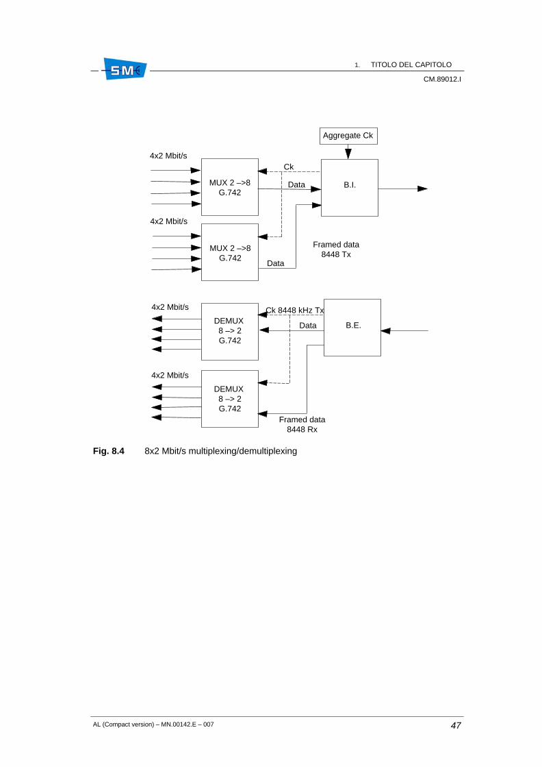
• Fig. 8.4 – 8x2 Mbit/s multiplexing. The eight 2 Mbit/s tributaries are grouped in two 4x2Mbit/s groups each of one generating a G742 frame structure at 8448 kbit/s to be sentto the next Bit Insertion. Opposite operation occurs at the Rx side.
• Fig. 8.5 – 16x2 Mbit/s multiplexing. The sixteen 2 Mbit/s tributaries are grouped in four4x2 Mbit/s groups each of one generating a G.742 frame structure at 8448 kbit/s. Afurther multiplexing of the achieved four 8448 kbit/s streams will generate a framestructure at 34368 kbit/s as per Recc. G.751. This latter is to be sent to the Bit Insertion.Opposite operation occurs at the Rx side.
The multiplexed tributaries are then sent to the B.I. for aggregate frame generation occurringat the following bit rate depending on various versions implemented:
Tab. 8.1
Version Aggregate frame
2x2 Mbit/s 4860 kbit/s
4x2 Mbit/s 9720 kbit/s
8x2 Mbit/s 19440 kbit/s
16x2 Mbit/s 38880 kbit/s
The aggregate frame contains:
• the main signal from the MUX(s)
• the framed service signal from the service interface
• the EOC signals for supervision message propagation towards the remote terminal
• the frame alignment word
• the bits dedicated to the FEC.
All the synch. signals to perform multiplexing (demultiplexing) and BI (BE) process are achievedfrom a x0 at 40 MHz. The aggregate frame thus generates is sent to the QAM modulator.
Rx side
Refer to Fig. 8.6.
At Rx side the Bit extraction separates the main multiplexed signal from the service signal andthen after a proper demultiplexing process (opposite to that previously described at the Tx side)sends them to the output interfaces.

1. TITOLO DEL CAPITOLOCM.89012.I
CM.89012.I
AL (Compact version) – MN.00142.E – 007 41
8.1.2 Radio interface
This functionality provides the following:
• QAM modemodulation
• power supply to IDU and ODU
• telemetry IDU/ODU
• cable interface
QAM modemodulation – Modulation side
See Fig. 8.7.
The aggregate signal from the BI undergoes the following process in digital form:
• serial to parallel conversion
• differential encoding
• generation of the shaped modulating signals feeding the IF part of the QAM modulator.
This latter comprises:
• recovery low pass filter to eliminate signal periodicity
• 330 MHz local oscillator
• a 90° phase shifter to supply two mixers with two in quadrature carriers
The thus obtained 330 MHz QAM modulated carrier is then sent to the cable interface forconnection with ODU.
QAM modemodulation – Demodulation side
See Fig. 8.7.
The 140 MHz, 4 or 16QAM modulated carrier from the ODU is reaching the IDU through thecable interface.
The connection to the demodulator input is made via a cable equalizer for cable losscompensation.
The IF section of the QAM demodulator extracts the I and Q analogue signals then digitalconverted for the following processing:
• clock recovery
• baseband equalisation and filtering
• bit polarity decision

1. TITOLO DEL CAPITOLOCM.89012.I
AL (Compact version) – MN.00142.E – 00742
• differential decoding
• parallel to serial conversion to recover the aggregate signal.
The aggregate signal is then sent to a frame alignment circuit and CRC analysis and then to theerror corrector to achieve the BER extimate, the PM and HBER/LBER alarms.
Power supply
Refer to Fig. 8.7. The –48 V battery voltage feeds the IDU and ODU circuitry. The servicevoltages for the IDU feeding are achieved through a DC/DC converter for +3.6 V generation anda step down circuit for –5V.
Both voltages are protected against overvoltages and overcurrents. The power to the ODU isgiven by the same battery running through the interconnection cable. A breaker protects thebattery against cable failure.
Telemetry IDU/ODU
Refer to Fig. 8.1 and Fig. 8.7. The dialogue IDU/ODU is made–up by the main controller andassociated peripherals within the ODU. Controls for ODU management and alarm reporting isperformed making use of a 388 kbit/s framed signals. The transport along the interconnetingcable is performed via two FSK modulated carriers: 17.5 MHz from IDU to ODU; 5.5 MHZ fromODU to IDU.
Cable interface
Refer to Fig. 8.7. This circuit permits to communicate to the far ODU through the interconnectingcable. It is mainly made up of a set of filters that:
• combine the 330 MHz, QAM modulated carrier/the 17.5 MHz carrier/the power supply
• separate the 140 MHz QAM modulated carrier and the 5.5 MHz carrier
8.1.3 Equipment controller
The controller functionality performs the following:
• houses the equipment software for equipment management
• interfaces the SCT/LCT program through supervision ports
• receive external alarms and route them to relay contacts along with the internal alarmsgenerated by the equipment.
The equipment software permits to control and manage all the equipment functionality. It isdistributed on two hardware levels: main controller and ODU peripheral controller. The dialoguebetween main and peripheral controllers is shown in Fig. 8.8.

1. TITOLO DEL CAPITOLOCM.89012.I
CM.89012.I
AL (Compact version) – MN.00142.E – 007 43
Main controller
The activities executed by the main controller are the following:
• Communication management: it makes use of SNMP as management protocol and IPor IP over OSI as communication protocol stacks. See Fig. 8.9 for details. The interfaceports for the equipment management are the following:
– LAN Ethernet 10BaseT
– USB port used for SCT/LCT connection
– EOC embedded within the PDH radio frame for connection to the remote NEs
• Log–in: the main controller manages the equipment or network login/logout by settingand then controlling the user’s ID and relevant password.
• Database (MIB): validation and storing in a non–volatile memory of the equipmentconfiguration parameters.
• Equipment configuration: distribution of the parameters stored in the MIB towards theperipheral µPs for their attuation in addition to the controls from user not stored in theMIB (i.e. loops, manual forcing etc...).
• Alarm monitoring: acquisition, filtering and correlation of the alarms gathered fromslaved µPs. Local logger and alarm sending to the connected managers: SCT/LCT –NMS5UX. Management of the alarm signalling on the LIM front panel.
• Performances: PM management as per Recc. G.828.
• Download: the main controller is equipped with two flash memory banks containing therunning program (active bank) and the stand–by program (inactive bank). This permitsto download a new software release to the inactive bank without distributing the traffic.Bank switch enables the new release to be used.Download activity is based on FTP protocol which downloads application programs,FPGA configuration, configuration files on main controller inactive bank or directly onthe peripheral controllers.
Peripheral controllers
The peripheral controllers take place within the ODU and are slaved to main controller with thetask of activating controls and alarm reporting of dedicated functionality.
8.2 IDU LOOPS
To control the IDU correct operation a set of local and remote loops are made available. Thecommands are forwarded by the LCT/SCT program. Loop block diagram is shown by Fig. 8.10.

1. TITOLO DEL CAPITOLOCM.89012.I
AL (Compact version) – MN.00142.E – 00744
8.2.1 Tributary loop
Tributary local loop
Each input tributary is routed directly to the trib. output upon receiving the command from theLCT. The Tx line transmission is still on.
Tributary remote loop
Each tributary directed towards the Rx output line is routed back to the Tx line. The Rx line isstill on.
8.2.2 Baseband unit loop
This kind of loop is only local and is activated at BI/BE level. Tx line is still on.
8.2.3 IDU loop
This kind of loop permits to check the full IDU digital operation.

1. TITOLO DEL CAPITOLOCM.89012.I
CM.89012.I
AL (Compact version) – MN.00142.E – 007 45
Fig. 8.1 Line interface block diagram – Tx side
Cod
eco
nver
ter
Cod
eco
nver
ter
MU
X2x
2/4x
28x
2/16
x2se
eF
ig. 8
.2th
roug
hF
ig. 8
.5
BI:
– m
ain
traf
fic–
serv
ices
– E
OC
– F
EC
– FA
W
Fra
me
gene
rato
rX
0 38
.88
MH
z
nx2
NR
Z
CK
NR
Z
CK
– F
SK
mod
/dem
od–
388
fram
e g
ener
ator
/rec
eive
r
to/fr
om m
ain
cont
rolle
r
Agg
rega
te fr
ame
5.5
MH
z
17.5
MH
z

1. TITOLO DEL CAPITOLOCM.89012.I
AL (Compact version) – MN.00142.E – 00746
Fig. 8.2 2x2 Mbit/s multiplexing/demultiplexing
MUXproprietary
frame
B.I.
DEMUXproprietary
frame
B.E.
Ck
Ck
Tx data
Rx data
2x2 Mbit/s
2x2 Mbit/s
Aggregate Ck
Fig. 8.3 4x2 Mbit/s multiplexing/demultiplexing
MUX 2 –>8G.742
B.I.
DEMUX 2 –>8G.742
B.E.
Ck
Ck
Framed data8448 Tx
Framed data8448 Rx
4x2 Mbit/s
4x2 Mbit/s
Aggregate Ck
1. TITOLO DEL CAPITOLOCM.89012.I
CM.89012.I
AL (Compact version) – MN.00142.E – 007 47
Fig. 8.4 8x2 Mbit/s multiplexing/demultiplexing
MUX 2 –>8G.742
B.I.
DEMUX 8 –> 2G.742
B.E.
Ck 8448 kHz Tx
4x2 Mbit/s
4x2 Mbit/s
Aggregate Ck
MUX 2 –>8G.742
Framed data8448 Tx
4x2 Mbit/s
DEMUX 8 –> 2G.742
4x2 Mbit/s
Framed data8448 Rx
Ck
Data
Data
Data

1. TITOLO DEL CAPITOLOCM.89012.I
AL (Compact version) – MN.00142.E – 00748
Fig. 8.5 16x2 Mbit/s multiplexing/demultiplexing
MUX2 –>8G.742
B.I.
4x2 Mbit/s
Aggregate Ck
MUX2 –>8G.742
4x2 Mbit/s
MUX2 –>8G.742
4x2 Mbit/s
MUX2 –>8G.742
4x2 Mbit/sMUX
8–>34G.751
Ck 8448 kHz Tx
Framed data8448 kbit/s Tx
Framed data 34368kbit/s
Ck 34368 kHz Tx
DEMUX8 –>2G.742
B.E.
4x2 Mbit/s
Aggregate Ck
DEMUX8 –>2G.742
4x2 Mbit/s
DEMUX8 –>2G.742
4x2 Mbit/s
DEMUX8 –>2G.742
4x2 Mbit/sMUX
34–>8G.751
Ck 8448 kHz
Framed data8448 kbit/s Tx
Framed data 34368kbit/s
Ck 34368 kHz

1. TITOLO DEL CAPITOLOCM.89012.I
CM.89012.I
AL (Compact version) – MN.00142.E – 007 49
Fig. 8.6 Line interface block diagram (Rx side)
from
dem
odul
ator
sid
e of
the
radi
o in
terf
ace
BE
DE
MU
X2/
2x2/
4x2
8x2/
16x2
See
Fig
. 8.2
thro
ugh
Fig
. 8.5
Cod
eco
nver
ter
Cod
eco
nver
ter
nx2
Mbi
t/s

1. TITOLO DEL CAPITOLOCM.89012.I
AL (Compact version) – MN.00142.E – 00750
Fig. 8.7 Radio interface block diagram
Cab
lein
terf
ace
Ove
rcur
rent
prot
ect.
Rem
ote
pow
er s
uppl
y
5.5
MH
z
QA
MM
OD
(IF
par
t)
330
MH
z
DC
DC
aggr
egat
e fr
ame
(fro
mB
I of l
ine
inte
rfac
e)
batte
ry–4
8 V
I/Vpr
otec
t
Ste
pdo
wn
+3.
6 V
–5 V
Cab
leeq
ualiz
.
DE
MQ
AM
(IF
par
t)
I&Q
17.5
MH
zfr
om li
ne in
terf
ace
to li
ne in
terf
ace
A
D–
Ck
reco
very
– C
arrie
r lo
ck–
Equ
aliz
. & fi
lt.–
Dec
isio
n –
Diff
. dec
od.
– S
/P
CR
C
anal
ysis
& a
ligne
r
FE
C
– B
ER
mea
s.–
P.M
.
– B
ER
ext
imat
es–
Hig
h B
ER
– Lo
w B
ER
– E
W
to B
E o
f lin
ein
terf
ace
– S
/P c
onve
rsio
n–
diff.
enc
odin
g–
mod
ulat
ing
si
gnal
gen
erat
or

1. TITOLO DEL CAPITOLOCM.89012.I
CM.89012.I
AL (Compact version) – MN.00142.E – 007 51
Fig. 8.8 Main and peripheral controller connection
Mai
n co
ntro
ller
338
kb/s
388
kbit/
s
LAN
US
BU
ser
InA
larm
/U
ser
Out
FS
Km
odem
FS
Km
odem
OD
U
EO
C
388
kbit/
sge
nera
tor
rece
iver
gen/
rec.
Per
iphe
ral
cont
rolle
r

1. TITOLO DEL CAPITOLOCM.89012.I
AL (Compact version) – MN.00142.E – 00752
Fig. 8.9 IP/IPoverOSI protocol stack
APPLICATION SOFTWARE
SNMP
TCP/UDP
IPIPoverOSI
IS–ISISO 10589
PPP PPPLLCMAC
LAPDQ921
LCCMAC
USB EOC EthernetLAN EOC
EthernetLAN
Applic./present.session layers
Transportlayer
Routinglayer
Data linklayer
Physicallayer

1. TITOLO DEL CAPITOLOCM.89012.I
CM.89012.I
AL (Compact version) – MN.00142.E – 007 53
Fig. 8.10 IDU loopback
MU
X
Trib
. loc
. loo
p
Trib
. IN
DE
MU
X
BI
BE
MO
D
Trib
. OU
T
Trib
. rem
.lo
op
DE
M
IDU
BB
loop
IFco
mbi
ner
IDU
loop

1. TITOLO DEL CAPITOLOCM.89012.I
AL (Compact version) – MN.00142.E – 00754

AL (Compact version) – MN.00142.E – 007 55
9. DESCRIPTION OF THE INDOORUNIT – ETHERNET INTERFACES
The indoor unit can be provided with Ethernet module option (V12252). In this way theequipment has both 2 Mbit/s and Ethernet ports, and the bit rate assigned to Ethernet traffic isthe nominal capacity of the radio minus enabled tributaries.
Description that follows covers Ethernet signal treatment, 2 Mbit/s signal treatment has beendescribed in previous chapter.
9.1 TREATMENT OF ETHERNET SIGNALS
In the place of V11 or (V28 + RS232) board it is possible to insert Ethernet Module.
In this way the IDU is equipped with the following interfaces:
• 3x electrical interface Ethernet 10/100 BaseT IEEE 802.3
• 16x2 Mbit/s (E1) interface
• total capacity from 2 to 64 Mbit/s
Most important functions are:
• multiplexing of 2 Mbit/s tributaries
• concatenation of 2 Mbit/s streams
• LAPS Link Access Procedure SDH (ITU X.86) for concatenated 2 Mbit/s
• bridge/switch between a local LAN port and the radio LAN port
• MAC switching
• MAC address learning
• MAC address ageing
• Ethernet interface with autonegotiation 10/100, full duplex, half duplex
– Ethernet interface with Flow Control, Back Pressure, MDI/MDX crossover
• network segmentation into bridge
ÎÎÎÎÎÎÎÎÎÎÎÎÎÎÎÎÎÎÎÎÎÎÎÎÎÎÎÎÎÎÎÎÎÎÎÎ
9

1. TITOLO DEL CAPITOLOCM.89012.I
AL (Compact version) – MN.00142.E – 00756
• virtual LAN as per IEEE 802.1q (anyone from 0 to 4095 VID for a maximum of 64memory location) (see Fig. 9.2)
• layer 2 QoS, priority management as per IEEE 802.1p (see Fig. 9.2)
• layer 3 ToS/DSCP (see Fig. 9.5)
• packet forwarding
A block diagram of IDU with Ethernet module can be found into Fig. 9.1.
In the IDU with Ethernet module there is a “switch” with 3 external ports and 1internal ports.External ports are electrical Ethernet 10/100BaseT interfaces placed on the front panel. Internalport is connected to radio side stream.
Ethernet traffic coming from external ports goes to internal port radio side. The radio side portis connected to one or two streams group of concatenated 2 Mbit/s. One stream for capacity upto 16x2 Mbit/s and two streams for capacity of 12 – 16 2 Mbit/s streams, plus other 16x2 Mbit/sstreams in case of maximum capacity.
The concatenated 2 Mbit/s are assembled in a protocol called LAPS similar to HDLC.
In Tx side Ethernet traffic is packet into a protocol called LAPS similar to HDLC. The resultingstream is divided into the used number of 2 Mbit/s streams. The 2 Mbit/s streams are thenmultiplexed, together with 2 Mbit/s arriving from front panel, the resulting stream goes to themodulator, see Fig. 9.1.
In Rx the stream arriving from the demodulator is divided into the 2 Mbit/s streams, then the 2Mbit/s not used into the front panel 2 Mbit/s are concatenated and sent to Ethernet circuits.Resulting stream, after LAPS protocol control, is sent to switch internal port.
9.1.1 2 Mbit/s tributaries
Tributary channels at 2 Mbit/s (E1), connected to relevant connectors into front panel, aremultiplexed as into standard IDU, see previous chapter.
From 0 to 16 tributaries can be selected to be used via SCT/LCT program, all the other available2 Mbit/s are sent to switch internal port.
9.1.2 Electrical Ethernet interface
The electrical Ethernet/Fast Ethernet interfaces are type IEEE 802.3 10/100BaseT with RJ45connector. For input or output signals at RJ45 please refer to User connection chapter. Cablecan be UTP (Unshielded Twisted Pair) or STP (Shielded Twisted Pair) Category 5.
Standard coding:
• Ethernet 10 Mbit/s: Manchester
• Fast Ethernet 100 Mbit/s: MLT–3 ternary
EMC/EMI protection:

1. TITOLO DEL CAPITOLOCM.89012.I
CM.89012.I
AL (Compact version) – MN.00142.E – 007 57
• Input and output pins are galvanically isolated through a transformer
• to reduce EMI every pin at RJ45 connector is terminated even if not used
• two signal lines are equipped with low capacity secondary protection to sustainresiduals of possible electrostatic discharges (ESD). With LCT/SCT program it is possible to activate autonegotiation (speed/duplex/flowcontrol) on 10/100BaseT interface.
9.1.3 Front panel LEDs of Ethernet ports
There are 2 Leds for any Ethernet interface:
• DUPLEX: color green, On = full duplex, OFF = half duplex
• LINK/ACT: color green, ON = link up without activity, OFF = link down, BLINKING = linkwith activity on Rx and Tx.
9.1.4 Bridge/switch function
A radio link equipped with Ethernet module can operate like a bridge/switch between two or moreseparated LANs with the following advantags:
• to connect two separated LANs at a distance even greater than the maximum limits of2.5 km (for Ethernet)
• to connect two LANs via radio within a complex digital network
• to keep separated the traffic into two LANs towards MAC filtering to get a total trafficgreater than traffic in a single LAN.
The bridge realized into Ethernet module is a transparent bridge (IEEE 802.1 part D) into thesame Vlan described by VLAN Configuration Table.
The bridge works at data link level, Layer 2 of OSI pile, and leave untouched Layer 3.
The bridge takes care to sendo traffic from a local LAN, to remote LAN.. Routing is only on thebasic of Level 2 addresses, sublevel MAC.
The operation of bridge is the following:
• when a bridge interface receives a MAC frame, the bridge on the basis of destinationaddress, decides which LAN to send it
• if destination address is on originating LAN the frame is descarded
• if destination address is a known address (towards address learning procedure) andis present into local address table the frame is sent only on destintion LAN (MACswitching)
• otherwise the frame is sent to all ports with the same VLAN ID (flooding).
A bridge is very different from a repeater, which copies slavishly everything that receives froma line on all the others. The bridge, in fact, acquires a frame, analyzes it, reconstruct it and routes

1. TITOLO DEL CAPITOLOCM.89012.I
AL (Compact version) – MN.00142.E – 00758
it. The bridge compensates also the different speeds of the interfaces, therefore an input canbe at 100 Mbit/s and output at 10 Mbit/s.
The mechanism is the following:
• from the moment of its activation, the bridge examines all the frames that arrive it fromdifferent LANs, and on these basis it builds its routing tables progressively.In fact, every received frame allows the bridge to know on what LAN the sending stationis located (MAC address learning).
• every frame that arrives to the bridge is rebroadcasted:
– if the bridge has the destination address into the routing table, sends the frameonly into the corresponding LAN
– otherwise the frame is sent to all the LANs except the originating (flooding)
– as soon as the bridge increases its knowledge of different machines, theretransmission becomes more and more selective (and therefore more efficient)
• the routing tables are updated every some minutes (programmable), removingaddresses not alive in the last period (so, if a machine is moved, within a few minuteit is addressed correctly) (MAC address ageing).
The whole process of bridging is restricted to the ports which are members of the same Vlan asdescribed into Vlan Configuration Table.
9.1.5 Ethernet Full Duplex function
The first realizations of the Ethernet network were on coaxial cable with the 10Base5 standard.
According to this standard Ethernet interfaces (e.g. PC) are connected to the coaxial cable inparallel and are normally in receiving mode. Only one PC, at a certain time, transmits on thecable, the others are receiving, so this is half duplex mode, and only one PC uses the recivedmessage.
Then the coaxial cable was progressively replaced by the pairs cable Unshielded Twisted Pair(UTP) as per 10BaseT standard. Normally there are four pairs into UTP Cat5 cable but two pairsare used with 10BaseT, one for Tx one for Rx. Into 10Base5 and 10BaseT standards, networkprotocols are the same the difference lays into the electrical interface. UTP cable is connectedpoint to point betwen a hub and a Ethernet interface. Network structure is a star where the serveris connected to a hub and from this a UTP cable is laid down for each Ethernet interface starts.
The further step is to replace the hub with a more powerful equipment, e.g. a switch. In this caseit is possible to activate transmission on both pairs at the same time, on one twisted pair for onedirection, on the other pair for opposite direction. Thus we obtain full duplex transmission onUTP.
Activating full duplex transmission it is possible to obtain a theoretical increase of performanceof nearly 100%. Full duplex mode can be activated into 10/100BaseT interfaces manually or withautonegotiation 100BaseFx operates always into full duplex mode.

1. TITOLO DEL CAPITOLOCM.89012.I
CM.89012.I
AL (Compact version) – MN.00142.E – 007 59
9.1.6 Link Loss Forwarding
Link Loss Forwarding (LLF) is an alarm status of ethernet interface.
LLF can be enabled or disabled. If LLF is enabled an US radio alarm condition will generate thealarm status of Ethernet interface blocking any transmission to it. LLF can be enabled for each3 ports at front panel. With LLF enabled the equipment connected (routers, switches so on) canbe notified that radio link is not available and can temporarerly reroute the traffic.
9.1.7 MDI/MDIX cross–over
The Ethernet electrical interface can be defined by SCT program as MDI or MDIX to cross–overbetween pairs so that external cross–over cable is not required.
9.1.8 VLAN functionality
LIM Ethernet module works with IEEE 802.1q and 802.1p tag for VLANs and QoS see Fig. 9.2.
The virtual LAN (VLAN) are logical separated subnets so that all the stations, into VLAN, seemto be into the same physical LAN segment even if they are geographically separated.
The VLAN are used to separate traffic on the same physical LAN too. Station operating on thesame physical LAN but on different VLAN work in separated mode thus they do not sharebroadcast and multicast messages. This results in a reduction of broadcast generated traffic andabove all we get more security thanks to network separation.
Tag position and structure are shown into Fig. 9.2.
Tag is made up with:
• a fixed word of 2 bytes
• 3 bits for priority according 802.1p
• 1 fixed bit
• 12 bits VLAN identifier (VLAN ID) according 802.1q.
Switch crossconnections are based on Vlan Configuration Table where input and output portsor only output ports should be defined for any used VID.
Vlan Configuration Table has 64 position for Vlan ID range from 1 to 4095.
9.1.9 Switch organized by port
The switch can be organized on port basis treating both Tagged and Untagged packets in thesame way.

1. TITOLO DEL CAPITOLOCM.89012.I
AL (Compact version) – MN.00142.E – 00760
For each input port it is possible to define where to route the incoming traffic; one or more of the3 other ports can be Enabled to exit the incoming traffic. It is possible, also, to route back theincoming traffic into the same port. This type of connection are monodirectional. For adibirectional connection between a generic Lan A and Lan B it is necessary to set the connectionfrom Lan A to Lan B and from Lan B to Lan A.
The IDU with Ethernet module has 3 physical ports and one internal port, radio side. The internalswitch can connect two or more ports together.
Then MAC address bridging rules will be applied to this packet. It is possible to select that apacket follows the description of Vlan Configuration Table for its Vlan ID.
Another selection is to follow only Vlan Configuration Table.
Packets can exit from a port as Unmodified or all Tagged either all Untagged. Unteggad packetswill take default tags.
For output operations there are 3 selections:
• Unmodified: tagged packets keep their tag. Untagged packets remain untagged
• Tagged: all the packets will exit tagged, tagged packets keep their tag, untaggedpackets take Default VID of incoming port.
• Untagged: all the packets will exit untagged.
9.1.10 Switch organized by VLAN ID
Vlan Configuration Table
Vlan Configuration Table defines a list of Vlan ID, For any Vlan ID some ports are members ofVlan others are not members. Ports members of a Vlan are allowed to receive and send packetswith that Vlan. Switch dinamically assignes packets to the output port according their VLAN ID.
Packets aren’t sent out to that port unless they belong to one of the Vlan of which the port is amember.
A port can be a member of a Vlan or many Vlan.
A port can be a member from 1 to 64 Vlans but tagged packets are dropped if their input portis not a member of packet’s Vlan.
After the control of packet and port Vlan membership MAC address bridging rules will be appliedto this packet.
Ingress Filtering Check
This is a process to check an incoming packet to compare its Valn ID to input port’s Vlanmembership. With Ingress Filtering Check it is possible to permit only to tagged packets to enterthe switch. If the port is not member of the Vlan n. XX all the incoming packets with Vlan ID XXwill be dropped.

1. TITOLO DEL CAPITOLOCM.89012.I
CM.89012.I
AL (Compact version) – MN.00142.E – 007 61
There are 3 option into Ingress Filtering Check to manage incoming packets:
• Disable: all Tagged and Untagged packets can transit into the switch following settingof swicth organized by port.
• Fallback: Untagged frames follow the rules of switch organized by port, Tagged frameswith Vlan ID described into the Vlan Configuration Table follow the rules of the table,Tagged frames with Vlan ID not described into the Vlan Configuration Table follow therules of switch organized by port.
• Secure: Untagged frames cannot enter the switch, Tagged frames with Vlan IDdescribed into the Vlan Configuration Table follow the rules of the table, Tagged frameswith Vlan ID not described into the Vlan Configuration Table cannot enter the switch.
Operations at the input. At the input port the packet is received and a switching decision mustbe made. The switch analyse the Vlan ID (if present) and decides whether and where to forwardthe frame. If the received packet is untagged, the switch sends the packet to the port specifiedinto incoming port “Lan per port” settings. If the packet is tagged the switch check the other 3destination ports to find at least one with the same Vlan ID and put the packet into output portqueue. If the Vlan ID is not listed into Vlan Configuration Table the switch sends the packet tothe port specified into incoming port “Lan per port” settings.
Then MAC address bridging rules will be applied to this packet.
Operations at the output. For each output port there are 3 selections for outgoing packets.
• Disable output port
• Enable unchanged: tagged packets keep their tag. Untagged packets remainuntagged.
• Enable tagged: all the packets will exit tagged with Vlan ID specified into VlanConfiguration Table, tagged packets keep their tag, untagged packets take Default VIDof incoming port.
• Untagged: all the packets will exit untagged.
9.1.11 Layer 2, Priority function, QoS, 802.1p
Some services as voice overIP and videoconference have some time limits to work properly. Asolution is to increase the priority of time sensitive packets. In this case random crowding comingfrom other services affects the delay of prioritized packets a lot less.
Into LIM Ethernet module different priority of incoming packets is managed using Tag definedinto IEEE 802.1p (see Fig. 9.2).
Every switch output port holds 4 output queues: queue 4 has highest priority, queue 0 has thelowest priority (see Fig. 9.3).
Priority can be organized by incoming port or by incoming priority tag:
• Priority by incoming port. For Untagged packets at each input ports it is decided to sendthe packets to one of the 4 queues of output ports defining which is the Default PriorityQueue: Queue = 0, 1, 2, 3. For Tagged packets it is necessary to Disable Priority sothey will go in the same queue of Untagged packets.

1. TITOLO DEL CAPITOLOCM.89012.I
AL (Compact version) – MN.00142.E – 00762
• Priority by incoming priority. For tagged packets for each priority tag (3 bits = for 7priority levels) it is possible to define where to send the packets, into Queue from 0 to3. Priority must be enable on 802.1p mode only or IpToS mode only (see nextparagraph) or first check 802.1p mode and IpToS mode either first check IpToS modeonly (see next paragraph) or first check 802.1p mode and IpToS mode either first checkIpToS mode and then 808.1q. For untagged packets the priority is defined only byincoming port.
Outgoing packet policy at output ports can be WFQ (Wait Fair Queue) with fixed proportionaloutput policy 8 packets from Queue 3, 4 from Queue 2, 4 from Queue 1, 1 from Queue 0.
Layer 3, Priority function, QoS, IP–V4 ToS (DSCP)
Only for IP packets it is possible to use incoming Layer 3 ToS (see Fig. 9.4) to prioritize incomingpackets. The 8 bits available can be read as 7 bits of ToS or 6 bits of DSCP as shown in Fig. 9.5.
According priority defined into ToS/DSCP the packet is sent into high priority queue low priorityqueue of output ports.
With SCT/LCT program it is possible to select a different output queue for any ToS/DSCP prioritylevel at each input port.

1. TITOLO DEL CAPITOLOCM.89012.I
CM.89012.I
AL (Compact version) – MN.00142.E – 007 63
Fig. 9.1 LIM Ethernet 2 Mbit/s block diagram
10/1
00B
aseT
10/1
00B
aseT
10/1
00B
aseT
LAP
S
MU
X16
x2M
bit/s
MU
X16
x2M
bit/s
CONCATENATED 2 Mbit/s
PD
Hra
dio
PDH RADIO
10/100BaseT 2 Mbit/s
0–16
x2 M
bit/s
Onl
y fo
r 32
x2 M
bit/s
ver
sion

1. TITOLO DEL CAPITOLOCM.89012.I
AL (Compact version) – MN.00142.E – 00764
Fig. 9.2 Tag control into field
Ethernet Layer 2 Header, non–802.1p
Destination Source Type/Length
Ethernet Layer 2 Header, 802.1p
Destination Source Tag Control Info Type/Length
8100 h
2–Bytes 3–Bits 1–Bit 12–Bits
Tagged frame type interpretation3 bit priorityfield 802.1p Canonical 12–bit 802.1q VLAN Identifier
Ethernet Layer 2 Header, 802.1p
Type = 2 byte (8100)Level 2 priority (802.1p) = 3 bit (value from 0 to 7)Level 2 VLAN (802.1q) = 12 bit (value from 1 to 4095)Canonical form = 1 bit (shows if MAC addresses of current frame are with canonical form:– C = 0 canonical form (MAC with LSB at left) (always into Ethernet 802.3 frames)– C = 1 canonocal form (MAC with MSB ay left) (token ring and some FDDI)
Fig. 9.3 Output queues
Queue 3
Queue 2
Queue 1
Queue 0
Output Port
Input port

1. TITOLO DEL CAPITOLOCM.89012.I
CM.89012.I
AL (Compact version) – MN.00142.E – 007 65
Fig. 9.4 ToS/DSCP tag position into IP packets
Version TOS Total Length
Total Length Flags Fragment Offset
IHL
TTL Protocol ID Header Checksum
Source IP Address
Destination IP Address
Options Padding
Data
4 4 8 16
Fig. 9.5 ToS/DSCP
0 1 2 3 4 5 6 7
MSB LSB
Not used
Not used
DSCP
ToS

1. TITOLO DEL CAPITOLOCM.89012.I
AL (Compact version) – MN.00142.E – 00766

AL (Compact version) – MN.00142.E – 007 67
10. CHARACTERISTICS OF THEOUTDOOR UNIT
10.1 GENERAL
The following ODU characteristics are guaranteed for the temperature range from –33° C to+55° C.
10.2 TECHNICAL SPECIFICATION
• see Tab. 10.1
•– 42 MHz (154 MHz duplex spacing)
56 MHz (161/168/196 MHz duplex spacing)84 MHz (245 MHz duplex spacing)
– 84 MHz
– 119 MHz
– 330 MHz
– 336 MHz
– 448 MHz
– 560 MHz
• 125 kHz step
•– 245/196/168/161/154 MHz
– 311,32 MHz
– 530 MHz
ÓÓÓÓÓÓÓÓÓÓÓÓÓÓÓÓÓÓÓÓÓÓÓÓÓÓÓÓÓÓÓÓÓÓÓÓ
10
Output power at the antenna side
Transceiver tuning range
7 GHz
13 GHz
15 GHz
18 GHz
23 GHz
25 GHz/28 GHz
38 GHz
RF frequency agility
Duplex spacing
7 GHz
8 GHz
11 GHz

1. TITOLO DEL CAPITOLOCM.89012.I
AL (Compact version) – MN.00142.E – 00768
– 266 MHz
– 420/490/728 MHz
– 1010 MHz
– 1008/1232 MHz
– 1008 MHz
– 1260 MHz
•– 40 dB
– 20 dB
• 40 dB dynamic, 1 dB software adjustable
• 40 dB
•– PBR84 or UBR84 3
– UDR120 or UBR140
– UDR140 or UBR140
– PBR220 or UBR220
– PBR320 or UBR320
• from –20 dBm to threshold corresponding to BER10–3
• ±3 dB in the range –40 dBm to –75 dBm±4 dB in the range –30 dBm to –40 dBm
• –20 dBm
• “N”
•– 330 MHz (from IDU to ODU)
140 MHz (from ODU to IDU)
– 388 kbit/s
– 17.5 MHz (from IDU to ODU)5.5 MHz (from ODU to IDU)
• RF loop
3. PBR with integrated antennaUBR with separated antenna
13 GHz
15 GHz
18 GHz
23 GHz
25 GHz/28 GHz
38 GHz
ATPC dynamic range
7, 8, 11, 13, 15 GHz
18, 23, 25, 28, 38 GHz
Transmit power attenuation range
Transmitter shut–down
Antenna side flange
7/8 GHz
13 GHz
15 GHz
18/23/25 GHz
28/38 GHz
AGC dynamic range
Accuracy of Rx level indication (PCreading)
Maximum input level for BER 10–3
Type of connector at the cable interface side
Signals at the cable interface
QAM modulated carrier
Telemetry
Telemetry carriers
Available loops

1. TITOLO DEL CAPITOLOCM.89012.I
CM.89012.I
AL (Compact version) – MN.00142.E – 007 69
Tab. 10.1 Nominal output power �1 dB tolerance
Equipment Output power 4QAM Output power 16QAM
7 GHz +27 dBm +22 dBm
8 GHz +27 dBm +22 dBm
11 GHz +25 dBm +20 dBm
13 GHz +25 dBm +20 dBm
15 GHz standard +25 dBm +20 dBm
15 GHz LP +20 dBm –
18 GHz +20 dBm +15 dBm
23 GHz +20 dBm +15 dBm
25 GHz +20 dBm +15 dBm
28 GHz +19 dBm +14 dBm
38 GHz +17 dBm +13 dBm
Note
In 1+1 hot stand–by version the output power decreases by the following values:
• –4 dB ±0.5 dB (balanced hybrid)
• –1.7/7 dB ±0.3 dB (unbalanced hybrid)

1. TITOLO DEL CAPITOLOCM.89012.I
AL (Compact version) – MN.00142.E – 00770
AL (Compact version) – MN.00142.E – 007 71
11. DESCRIPTION OF THE OUTDOORUNIT
11.1 GENERAL
The 1+0 ODU (refer to Fig. 11.1) consists of a two shell aluminium mechanical structure, oneshell housing all the ODU circuits, the other forming the covering plate.
On the ODU are accessible:
• the “N” type connector for cable interfacing IDU and ODU
• the “BNC” connector for connection to a multimeter with the purpose to measure thereceived field strength
• a ground bolt.
The 1+1 hot stand–by version (refer to Fig. 11.2) consist of two 1+0 ODUs mechanically securedto a structure housing the hybrid for the antenna connection.
11.2 TRANSMIT SECTION
Refer to block diagram shown in Fig. 11.3.
The 330 MHz QAM modulated carrier from the cable interface (see chapter 11.4) is forwardedto a mixer passing through a cable equalizer for cable loss compensation up to 40 dB at 330MHz. The mixer and the following bandpass filter give rise to a second IF Tx carrier thefrequency of which depends on the go/return frequency value. The mixer is of SHP type.
The IF Tx frequency is µP controlled. Same happens to Rx IF and RF local oscillators. This latteris common to both Tx and Rx sides.
ÓÓÓÓÓÓÓÓÓÓÓÓÓÓÓÓÓÓÓÓÓÓÓÓÓÓÓÓÓÓÓÓÓÓÓÓ
11

1. TITOLO DEL CAPITOLOCM.89012.I
AL (Compact version) – MN.00142.E – 00772
The IF carrier is converted to RF and then amplified making use of a MMIC circuit. Theconversion mixer is SSB type with side band selection.
The power at the MMIC output can be manually attenuated, 1 dB step, by 20 dB (f ≥ 18 GHz)or 40 dB (f < 18 GHz). Total attenuation is 40 dB.
The automatic adjustment is performed making use of an ATPC (see paragraph 11.5 for details).
The regulated output power is kept constant against amplifier stage gain variation by a feedbackincluding the AGC.
Before reaching the antenna side the RF signal at the output of MMIC passes through thefollowing circuits:
• a decoupler plus detector diode to measure the output power
• a circulator to protect the amplifier stages against possible circuit mismatch.
• a ON/OFF switch for 1+1 operation
• a 0 or 20 dB attenuator (f ≥ 18 GHz) to made up a total attenuation of 40 dB
• an RF bandpass filter for antenna coupling.
An RF coupler plus a detector and a shift oscillator made up the RF loop which is enabled uponreceiving a µP control. The RF loop permits the Tx power to return back to receive side thuscontrolling the total local radio terminal performance.
11.3 RECEIVE SECTION
The RF signal from the Rx bandpass filter is sent to a low noise amplifier that improves thereceiver sensitivity.
The following down–converter translates the RF frequency to approximately 765 MHz.
The conversion mixer is SSB type. The sideband selection is given through a µP control.
A second down converter generates the 140 MHz IF carrier to be sent to the demodulator withinthe IDU. The level of the IF carrier is kept constant to –5 dBm thank to the IF amplifier stages,AGC controlled, distributed in the IF chain. In addition the AGC gives a measure of the receiveRF level.
Between two amplifiers a bandpass filter assures the required selectivity to the receiver. Thefilter is SAW type and the bandwidth depends on the transmitted capacity.

1. TITOLO DEL CAPITOLOCM.89012.I
CM.89012.I
AL (Compact version) – MN.00142.E – 007 73
11.4 CABLE INTERFACE
The cable interface permits to interface the cable interconnecting IDU to ODU and viceversa.
It receives/transmits the following signals:
• 330 MHz (from IDU to ODU)
• 140 MHz (from ODU to IDU)
• 17.5 MHz (from IDU to ODU)
• 5.5 MHz (from ODU to IDU)
• remote power supply.
The 17.5 MHz and 5.5 MHz FSK modulated carriers, carry the telemetry channel. This latterconsists of two 388 kbit/s streams one from IDU to ODU with the information to manage the ODU(RF power, RF frequency, capacity, etc...) while the other, from ODU to IDU, sends back to IDUmeasurements and alarms of the ODU. The ODU management is made by a µP.
11.5 ATPC OPERATION
The ATPC regulates the RF output power of the local transmitter depending on the value of theRF level at the remote terminal. This value has to be preset from the local terminal as thresholdhigh and low. The difference between the two thresholds must be equal or higher than 3 dB.
As soon as the received level crosses the preset threshold level low (see Fig. 11.6) due to theincrease of the hop attenuation, a microP at the received side of the remote terminal sends backto the local terminal a control to increase the transmitted power. The maximum ATPC range is40 dB (f < 18 GHz) and 20 dB (f ≥ 18 GHz).
If the hop attenuation decreases and the threshold high is crossed then the control sent by themicroP causes the output power to decrease.
ATPC range can be reduced from the maximum value to 0 dB, by 1 dB step, consequently toa reduction of the output maximum power through an adjusted attenuation.

1. TITOLO DEL CAPITOLOCM.89012.I
AL (Compact version) – MN.00142.E – 00774
11.6 1+1 Tx SYSTEM
The two ODUs are coupled to the antenna side via a balanced or unbalanced hybrid.
1+1 Tx switching occurs in the 1+1 hot stand–by 1 antenna or 2 antennas versions as shownin Fig. 11.4 and Fig. 11.5.
The transmitter switchover is electromechanic type and consists of two ON/OFF switches withinthe two ODUs that assure at least 40 dB insulation on the stand–by transmitter.
Transmit alarm priority is shown in Tab. 11.1.
Tab. 11.1
Priority Levels Definition
Priority 1 RIM PSU Alarm
Priority 2 Manual forcing
Priority 3 Cable Short Alarm
Priority 3 Cable Open Alarm
Priority 3 Modulator Failure
Priority 3 ODU Unit Failure Alarm
Highest Priority 3 VCO Failure Alarm
Priority 3 IF Unit Alarm
Priority 3 ODU PSU Alarm
Priority 3 Tx Power Low Alarm
Priority 4 Request from remote terminal(both receivers alarmed)
Lowest Priority 5 Revertive Tx (branch one prefe-rential)

1. TITOLO DEL CAPITOLOCM.89012.I
CM.89012.I
AL (Compact version) – MN.00142.E – 007 75
11.7 POWER SUPPLY
The battery voltage is dropped from the cable interface and then sent to a DC/DC converter togenerate three stabilized output voltages to be distributed to the ODU circuitry:
• +3.5 V
• a voltage comprised between +6.2 V and +8.2 V to power amplifiers operating atdifferent frequency bands
• a –12 V through an inverter circuit.
Each voltage is protected against overcurrent with automatic restart.
Protection against overvoltage occurs as soon as the output voltage raises more than 15%respect to the nominal voltage. The restart is automatic.
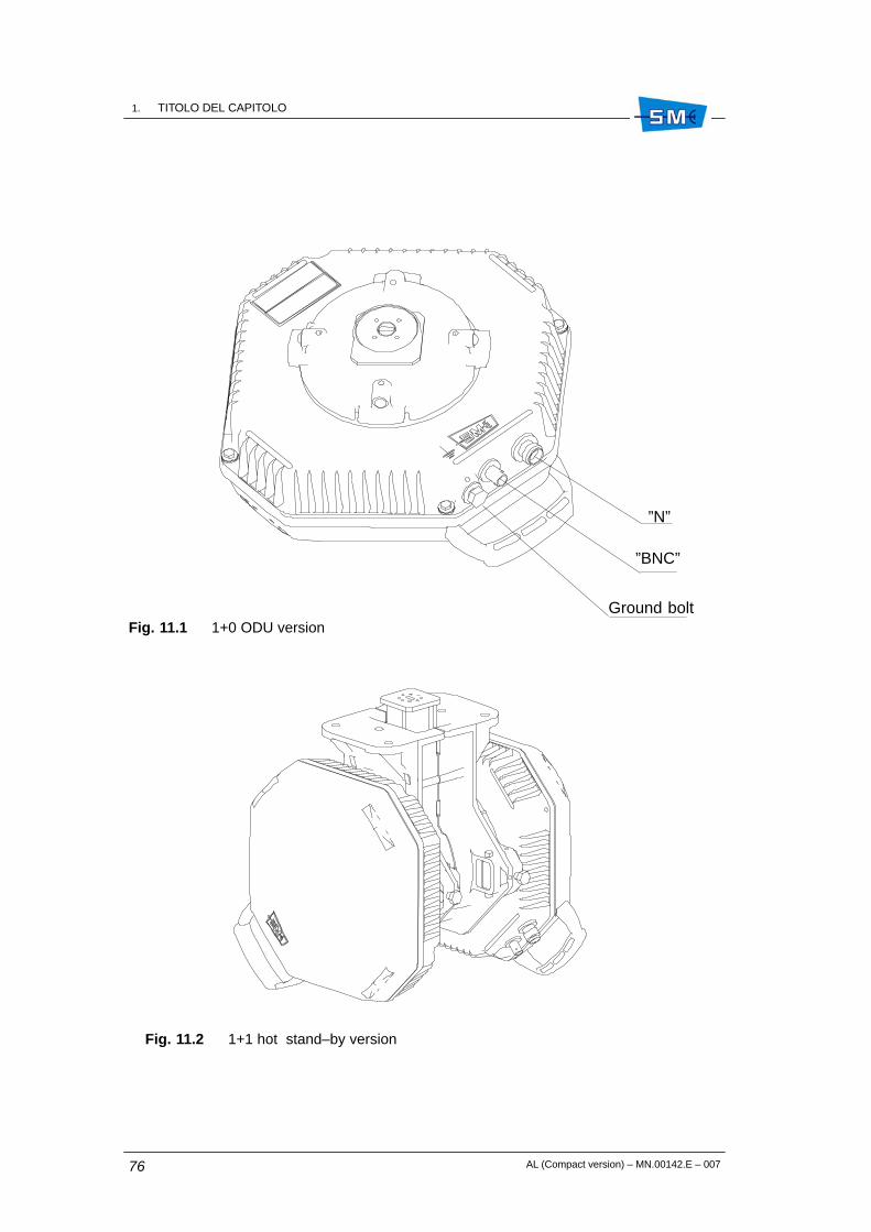
1. TITOLO DEL CAPITOLOCM.89012.I
AL (Compact version) – MN.00142.E – 00776
Fig. 11.1 1+0 ODU version
”N”
”BNC”
Ground bolt
Fig. 11.2 1+1 hot stand–by version

1. TITOLO DEL CAPITOLOCM.89012.I
CM.89012.I
AL (Compact version) – MN.00142.E – 007 77
Fig. 11.3 ODU block diagram
Cab
lein
terf
ace
Cab
leeq
ualiz
.
DC
DC
Ste
pup
T
LNA
MM
IC
varia
ble
bw(c
apac
ityde
pend
ing)
AG
C
N ty
pe33
0M
Hz
–48
V
x
PR
x m
eas
140
MH
z14
0M
Hz
appr
ox.
765
MH
z
+3.5
V
+6.
2 to
8.2
V
–12
V
AG
C
x
PT
x at
t.co
ntro
l0
to 4
0 dB
IF L
Oun
it
MO
D5.
5M
Hz
RE
C17
.5M
Hz
DE
M17
.5M
Hz
MU
XD
EM
UX
388
kbit/
s
Ala
rmm
anag
&co
ntro
l
Alm
com
m
loop
s
5.5
MH
z
17.5
MH
z
388
kbit/
s
IF T
x
ante
nna
side
INV
BN
C
PR
xm
eas.
ctrl
RF
LO
unit R
x
Tx
RF
loop
ctrl
ctrl
ctrl
Rx
Tx

1. TITOLO DEL CAPITOLOCM.89012.I
AL (Compact version) – MN.00142.E – 00778
Fig. 11.4 1+1 hot stand–by 1 antenna
Antennaside
SW control
Tx side
Rx side
SW control
Tx side
Rx side
Fig. 11.5 1+1 hot stand–by 2 antennas
Firstantenna
SW control
Tx side
Rx side
SW control
Tx side
Rx side
Secondantenna

1. TITOLO DEL CAPITOLOCM.89012.I
CM.89012.I
AL (Compact version) – MN.00142.E – 007 79
Fig. 11.6 ATPC operation
Thresh High
Thresh Low
Hop attenuation (dB)
20 dBATPC range
PTxmax.
PTxmin.
RemotePRxdBm
LocalPTxdBm
Hop attenuation (dB)
Tx
Rx
Rx
Tx
PTxactuation
Local Remote
PRx recording
Transmission
of PTx control
µP µPlevel
PTx control

1. TITOLO DEL CAPITOLOCM.89012.I
AL (Compact version) – MN.00142.E – 00780

AL (Compact version) – MN.00142.E – 007 81
12. 24/48 VOLT DC/DC CONVERTERD52089
12.1 GENERAL
The 24/48V DC/DC converter D52089 is a unit which converts the voltage of 24 Vdc in –48 Vdc.
This unit is housed in a subrack 1 RU unit G52004 with two D52089 units (1+1version). For 1+0version the subrack is G52003 with one D52089 unit and the remaining half front panel has acover.
These subracks have a free air gap for cooling purpose.
The DC/DC converter unit D52089 is shown in Fig. 12.1.
Fig. 12.1 DC/DC converter front coverplate
+ – – +
6,3A250V
M ON 24VdcIN
48VdcOUT2A
ALARM
Green LED CM2 connector
Fuse 6.3 A 24 Vdc input male 3W3 connector
48 Vdc output female 3W3 connector
ÓÓÓÓÓÓÓÓÓÓÓÓÓÓÓÓÓÓÓÓÓÓÓÓÓÓÓÓÓÓÓÓÓÓÓÓ
12

1. TITOLO DEL CAPITOLOCM.89012.I
AL (Compact version) – MN.00142.E – 00782
12.2 ENVIRONMENTAL CONDITIONS
• –10° � 50° C
• –40° � 80° C
• 90% max in the range –5° � 30° C
12.3 ELECTRICAL CHARACTERISTICS
• 24 Vdc (20.4 � 28.8 Vdc floating)
• 52 Vdc
• 4.5 A
• 90 W
• 75 W
• ≤ 200 mVpp
• ETS 300 132–2
• ETS 300 132–2
• ETS 300 132–2
• ETS 300 132–2 (ETR 283)
• ETS 300 132–2
• ETS 300 132–2
• EN 300 086
• EN 60950–1
• – input polarity inversion (fuse)– surge input current (fuse)– continuous short circuit at output with automatic recovery
Operational range
Storage range
Operational humidity
Vinput
Voutput
Max current in input
Max 24 Vdc consumption
Max 48 Vdc load
Secondary voltage ripple
Surge current (Inrush current)
Conducted immunity
Conducted emission
Short duration voltage transient
Abnormal service voltage
Voltage changes due to the regu-lation of power supply
Electromagnetic compatibility
Safety
Protections against

1. TITOLO DEL CAPITOLOCM.89012.I
CM.89012.I
AL (Compact version) – MN.00142.E – 007 83
• ON = green led active on input primary voltagepresent
• with relay contact on 9 pin male SUB–DconnectorAlarm off: 8–9 pin open, 7–9 pin closedAlarm on when Vout decreases ≥ 15%: 8–9 pinclosed, 7–9 pin open
• 6.3 A medium time 250 Volt
Fig. 12.2 shows connection from IDU 1+0 AL compact version to 24/48 V converter with cableF03489.
Fig. 12.3 shows connections from IDU 1+1 AL compact version to 24/48 V converter with cablesF03489 and F03278.
Warning: connect only 24 Vdc to primary input 24 Vdc IN.
Warning: power supply from –48 Vdc must be connected directly to ALC IDU.
Visual indication
Alarm (CM2 connector)
Fuse
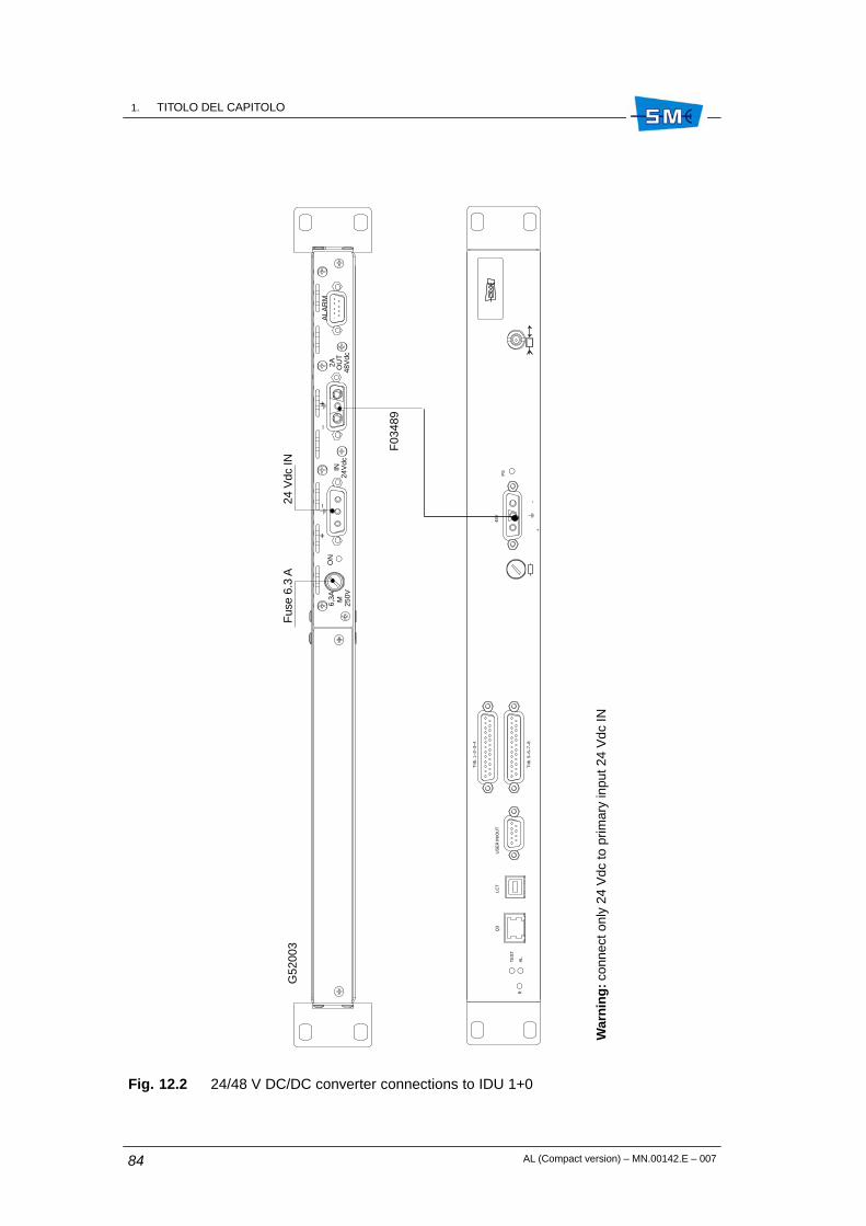
1. TITOLO DEL CAPITOLOCM.89012.I
AL (Compact version) – MN.00142.E – 00784
Fig. 12.2 24/48 V DC/DC converter connections to IDU 1+0
250VM
6,
3AO
NIN
24V
dc
2A OU
T48
Vdc
ALA
RM
+
––
+
F03
489
Fus
e 6.
3 A
24 V
dc IN
48V
+–
Trib
. 1–2
–3–4
Trib
. 5–6
–7–8
PS
LCT
Q3
US
ER
IN/O
UT
R
TE
ST
AL
G52
003
War
nin
g: c
onne
ct o
nly
24 V
dc to
prim
ary
inpu
t 24
Vdc
IN

1. TITOLO DEL CAPITOLOCM.89012.I
CM.89012.I
AL (Compact version) – MN.00142.E – 007 85
Fig. 12.3 24/48 V DC/DC converter connections to IDU 1+1
250VM
6,
3AO
NIN
24V
dc2A OU
T
48V
dcA
LAR
M
M25
0V
6,
3AO
NIN
24V
dc
2AOU
T48
Vdc
ALA
RM
+
––
+
+
––
+
21
RX
TX
AL
TE
ST
R
US
ER
IN/O
UT
Q3
LCT
PS
2
PS
1
Trib
. 13–
14–1
5–16
Trib
. 5–6
–7–8
Trib
. 9–1
0–11
–12
Trib
. 1–2
–3–4
21
21
48V
2
+
––
+
48V
1
F03
278
F03
489
24 V
dc IN
24 V
dc IN
Fus
e 6.
3 A
Fus
e 6.
3 A
War
nin
g: c
onne
ct o
nly
24 V
dc to
prim
ary
inpu
t 24
Vdc
IN

1. TITOLO DEL CAPITOLOCM.89012.I
AL (Compact version) – MN.00142.E – 00786

AL (Compact version) – MN.00142.E – 007 87
ÓÓÓÓÓÓÓÓÓÓÓÓÓÓÓÓÓÓÓÓÓÓÓÓÓÓÓÓÓÓÓÓÓÓÓÓÓÓÓÓÓÓÓÓÓÓÓÓÓÓÓÓÓÓÓÓÓÓÓÓÓÓÓÓÓÓÓÓÓÓÓÓÓÓÓÓÓÓÓÓÓÓÓÓÓÓÓÓÓÓÓÓÓÓÓÓÓÓÓÓÓÓÓÓÓÓÓÓÓÓÓÓÓÓÓÓÓÓÓÓÓÓÓÓÓÓÓÓÓÓÓÓ
3Section
Installation

1. TITOLO DEL CAPITOLOCM.89012.I
AL (Compact version) – MN.00142.E – 00788

AL (Compact version) – MN.00142.E – 007 89
13. INSTALLATION AND PROCEDURESFOR ENSURINGELECTROMAGNETICCOMPATIBILITY
13.1 GENERAL
The equipment consists of IDU and ODU(s) units and is mechanically made up of a wired 19”subrack (IDU) and a weather proof metallic container (ODU). The two units are shipped togetherin an appropriate cardboard box.
After unpacking, mechanical installation takes place followed by electrical connections asdescribed in the following paragraphs.
13.2 MECHANICAL INSTALLATION
13.2.1 IDU installation
The front side of the IDU mechanical structure is provided with holes at the sides. This allowsto fasten the subrack to a 19” rack by means of four M6 screws.
If two or more IDUs are to be mounted, leave at least 1/2 rack unit space (22 mm) between twoIDUs to avoid overheating problems.
ÎÎÎÎÎÎÎÎÎÎÎÎÎÎÎÎÎÎÎÎÎÎÎÎÎÎÎÎÎÎÎÎÎÎÎÎ
13

1. TITOLO DEL CAPITOLOCM.89012.I
AL (Compact version) – MN.00142.E – 00790
13.3 ELECTRICAL WIRING
The electrical wiring must be done using appropriate cables thus assuring the equipmentcomplies with electromagnetic compatibility standards.
The cable terminates to flying connectors which have to be connected to the correspondingconnectors on the equipment front.
Position and pin–out of the equipment connectors are available in this section.
Tab. 13.1 shows the characteristics of the cables to be used and the flying connector types.
Tab. 13.1
Interconnecting points Type of connector termina-ting the cable
Type of cable/conductor
Battery Polarised SUB–D 3W3 femaleconnector
Section of each wire ≥ 2.5sq.mm
4
Tributary signals 25 pin SUB–D male connector 120 Ohm balanced four sym-metric pairs with shield
Coaxial connector 1.0/2.3 75 Ohm unbalanced with shield
User input/alarm output 9 pin SUB–D female connectorwith shielded holder
9 conductor cable with doublebrass sheath type interconduc-tor DB28.25 or equivalent
LCT USB connector USB connector
GND Faston male type Section area ≥ 6 sq. mm.
4. For power cable lenght longer than 20 m. a section of 4 mm is required.

1. TITOLO DEL CAPITOLOCM.89012.I
CM.89012.I
AL (Compact version) – MN.00142.E – 007 91
13.4 GROUNDING CONNECTION
Fig. 13.1 and annexed legend show how to perform the grounding connections.
Fig. 13.1
IDUunit
ODUunit
2
6(+) (–)
4
Localground
Legend
(1) IDU grounding point, fast–on type. The cross section area of the cable used must be≥ 4 sq. mm. The fast–on is available on both sides of the IDU.
(2) ODU grounding bolt. The cross section area of the cable used must be ≥ 16 sq. mm
(3) IDU–ODU interconnection cable type Celflex CUH 1/4” terminated with N–type maleconnectors at both sides.
(4) Grounding kit type Cabel Metal or similar to connect the shield of interconnectioncable.
(5) Matching cable (tail) terminated with SMA male and N female connectors.
(6) Battery grounding point of IDU to be connected to earth by means of a cable with asection area 2.5 sq. mm. Length ≤ 10 m.
(7) Grounding cords connected to a real earth inside the station. The cross section areaof the cable must be ≥ 16 sq. mm
rackground
Indoor
Stationground
7
1 5
3 4 3

1. TITOLO DEL CAPITOLOCM.89012.I
AL (Compact version) – MN.00142.E – 00792

AL (Compact version) – MN.00142.E – 007 93
14. USER CONNECTIONS
14.1 CONNECTOR USE FOR 1+0/1+1 STANDARD VERSION
User connections are performed through connectors on the IDU front panel modules (seeFig. 14.1). The connectors are the following:
• Trib IN/OUT: 75 or 120 25–pin SUB–D male connector. For SUB–D connector detailsTab. 14.1.
• LCT: USB connector B type “Receptacle”. For connector detail see USB standard.
• USER IN/OUT: SUB–D male connector. Connector details refer to Tab. 14.6.
• Q3: RJ45 connector. Connector details refer to Tab. 14.2.
• 50 Ohm connector for interconnection to ODU 5.
• 48V: 3 pin SUB–D 3W3 connector for interconnection to battery.
• V11: optional service interface. Connector details in Tab. 14.3.
• V.28: optional service interface. Connector details in Tab. 14.4.
• RS232 PPP: optional management interface. Connector details in Tab. 14.5.
Fig. 14.1 IDU 1+1 standard (2x2/4x2/8x2/16x2 Mbit/s)
21
RXTX
AL
TESTR
USER IN/OUTQ3 LCT
PS2
PS1
Trib. 13–14–15–16Trib. 5–6–7–8
Trib. 9–10–11–12Trib. 1–2–3–4
2121
48V2
+ ––
+
48V1
5. SMA kind: max torque 0.5 Nm
ÓÓÓÓÓÓÓÓÓÓÓÓÓÓÓÓÓÓÓÓÓÓÓÓÓÓÓÓÓÓÓÓÓÓÓÓ
14

1. TITOLO DEL CAPITOLOCM.89012.I
AL (Compact version) – MN.00142.E – 00794
14.2 STANDARD VERSION CONNECTORS
Tab. 14.1 Tributary connector pin–out (male 25 pin SUB–D)
Pin 120 Ohm impedance Pin 75 Ohm impedance Note
1 Tributary 1/5/9/13 input (cold wire) 1 Ground
2 Tributary 1/5/9/13 input (hot wire) 2 Tributary 1/5/9/13 input
14 Tributary 1/5/9/13 input (ground) 14 Ground
15 Tributary 1/5/9/13 output (cold wire) 15 Ground
16 Tributary 1/5/9/13 output (hot wire) 16 Tributary 1/5/9/13 output
3 Tributary 1/5/9/13 output (ground) 3 Ground
4 Tributary 2/6/10/14 input (cold wire) 4 Ground
5 Tributary 2/6/10/14 input (hot wire) 5 Tributary 2/6/10/14 input
17 Tributary 2/6/10/14 input (ground) 17 Ground
18 Tributary 2/6/10/14 output (cold wire) 18 Ground
19 Tributary 2/6/10/14 output (hot wire) 19 Tributary 2/6/10/14 output
6 Tributary 2/6/10/14 output (ground) 6 Ground
7 Tributary 3/7/11/15 input (cold wire) 7 Ground
8 Tributary 3/7/11/15 input (hot wire) 8 Tributary 3/7/11/15 input
20 Tributary 3/7/11/15 input (ground) 20 Ground
21 Tributary 3/7/11/15 output (cold wire) 21 Ground
22 Tributary 3/7/11/15 output (hot wire) 22 Tributary 3/7/11/15 output
9 Tributary 3/7/11/15 output (ground) 9 Ground
10 Tributary 4/8/12/16 input (cold wire) 10 Ground
11 Tributary 4/8/12/16 input (hot wire) 11 Tributary 4/8/12/16 input
23 Tributary 4/8/12/16 input (ground) 23 Ground
24 Tributary 4/8/12/16 output (cold wire) 24 Ground
25 Tributary 4/8/12/16 output (hot wire) 25 Tributary 4/8/12/16 output
12 Tributary 4/8/12/16 output (ground) 12 Ground
13 Ground 13 Ground
Note: The 75 Ohm impedance tributary connector pin–out is referred to the flying connectorsto be connected to the equipment connectors.

1. TITOLO DEL CAPITOLOCM.89012.I
CM.89012.I
AL (Compact version) – MN.00142.E – 007 95
Tab. 14.2 100BaseT connector pin–out for 10/100BaseT Ethernet connection
Pin Description
1 Tx+
2 Tx–
3 Rx+
4 ––
5 ––
6 Rx–
7 ––
8 ––
Tab. 14.3 Connector pin–out for 64 kbit/s channel – V.11 interface
Pin Description
1 D–V11–Tx
2 D+V11–Tx
3 C–V11–Tx
4 C+V11–Tx
5 D–V11–Rx
6 D+V11–Rx
7 C–V11–Rx
8 C+V11–Rx
Tab. 14.4 Connector pin–out – V.28 interface
Pin Description
1 RTS
2 TD
3 DTR
4 DSR
5 GND
6 RD
7 CTS
8 DCD

1. TITOLO DEL CAPITOLOCM.89012.I
AL (Compact version) – MN.00142.E – 00796
Tab. 14.5 Connector pin–out – RS232 PPP interface
Pin Description
1 DCD
2 RD
3 TD
4 DTR
5 GND
6 DSR
7 RTS
8 CTS
9 NC
Tab. 14.6 User in/out connector pin–out
Pin Description
1 C relay contact
2 NA/NC relay contact
3 User input 01
4 User input 02
5 GND
6 NC
7 User input 03
8 User input 04
9 NC

AL (Compact version) – MN.00142.E – 007 97
15. INSTALLATION ONTO THE POLE OFTHE ODU WITH SEPARATEDANTENNA
15.1 INSTALLATION KIT
Following installation kits are supplied with the equipment depending on different versions:
• 1+0 standard version
– antisliding strip (see Fig. 15.1)
– supporting plate plus 60–114 mm pole fixing bracket and relevant nuts and bolts(see Fig. 15.2)
– adapting tools and relevant bolts and nuts for 219 mm pole (see Fig. 15.3)
– antenna side flange, variable as function of RF frequency (see Fig. 15.4)
– support with ODU fast locking mechanism (see Fig. 15.2)
– flexible waveguide trunk for connection to antenna (optional) (see Fig. 15.2)
– kit for ground connection making part of ODU
• 1+0 Band–it version
– band–it strip (see Fig. 15.6)
– antenna side flange, variable as function of RF frequency (see Fig. 15.4)
– support with ODU fast locking mechanism (see Fig. 15.2)
– flexible waveguide trunk for connection to antenna (optional) (see Fig. 15.2)
– kit for ground connection making part of ODU
• 1+1 version
– antisliding strip (see Fig. 15.1)
– supporting plate plus pole fixing bracket and relevant nuts and bolts (see Fig. 15.2)
ÓÓÓÓÓÓÓÓÓÓÓÓÓÓÓÓÓÓÓÓÓÓÓÓÓÓÓÓÓÓÓÓÓÓÓÓ
15

1. TITOLO DEL CAPITOLOCM.89012.I
AL (Compact version) – MN.00142.E – 00798
– adapting tools and relevant bolts and nuts for 219 mm pole (see Fig. 15.3)
– hybrid with ODU fast locking mechanism (see Fig. 15.5)
– flexible waveguide trunk for connection to antenna (optional (see Fig. 15.2)
– kit for ground connection making part of the two ODUs.
15.2 REQUIRED TOOLS FOR MOUNTING (NOT SUPPLIED)
• N.2 13mm torque wrench or spanner
• N.1 15 mm torque wrench or spanner
• N.1 17 mm torque wrench or spanner
• N.1 3 mm Allen wrench
• N.1 2.5 mm Allen wrench
• N.1 7 mm torque wrench
• Fastening tool UIT19 (Band–it mounting kit only)
15.3 INSTALLATION PROCEDURE
Installation procedure proceeds according to the following steps:
• 1+0 standard: installation onto the pole of the supporting plate 6
• 1+0 Band–it: installation onto the pole of the supporting plate
• 1+1: installation onto the pole of the supporting plate 6
• Installation of the ODU (common to both 1+0 and 1+1 version)
• ODU grounding
1+0 standard – Installation onto the pole of the supporting plate
Fig. 15.1 – Mount antislide strip around the pole. The position of the plastic blocks depends onthe position of the supporting plate (see next step)
Fig. 15.2 – Adhere the supporting plate to the antisliding strip plastic blocks and then secure itto the pole through the fixing bracket for 60–114 mm pole (see Fig. 15.2). Bolts and nuts areavailable on the supporting plate. Tightening torque must be 32 Nm.
Warning: As shown in Fig. 15.3 an adapting kit must be used for the 219 mm pole. It consistsof an additional plate to enlarge the standard supporting plate dimension and relevant U–boltfor 219 mm pole fixing.
6. In case of 219 mm pole, an adapting kit is supplied for the purpose.

1. TITOLO DEL CAPITOLOCM.89012.I
CM.89012.I
AL (Compact version) – MN.00142.E – 007 99
Fig. 15.4 – Fix the flexible waveguide to the antenna side flange. Four fixing screws are availablethe dimensions of which depend on the waveguide type. Tighten progressively and alternativelythe four screws with the following torque:
Tab. 15.1
Frequencies Screw Tool Torque
from 18 to 38 GHz Allen screw M3 Allen key 2.5 mm 1 Nm
up to 15 GHz Allen screw M4 Allen key 3 mm 2 Nm
Fig. 15.4 – Fix the antenna side flange to the support with ODU fast locking mechanism. Theflange can be mounted horizontally (as shown in Fig. 15.4) or vertically as function ofconvenience.
Fig. 15.5 – Fix the support with ODU fast locking mechanism to the supporting plate making useof available bolts and nuts. Fig. 15.5 shows three possible positions. Tightening torque must be18 Nm.
1+0 Band–it
In case of 1+0 ODU installation, a band–it pole mounting kit can be used: through slots (seeFig. 15.6) on the supporting plate two metallic bands secure the plate on the pole by means ofclips (use Band–it fastening tool). Band characteristics are:
• thickness 0.76 mm
• width 19 mm
• steel stainless strip AISI 201/304 (3/4”)
• clips stainless steel AISI 201/304 (3/4”)
Fig. 15.4 – Fix the flexible waveguide to the antenna side flange. Four fixing screws are availablethe dimensions of which depend on the waveguide type. Tighten progressively and alternativelythe four screws with the following torque (see Tab. 15.1).
1+1 – Installation onto the pole of the supporting plate
Fig. 15.1 – Mount antislide strip around the pole. The position of the plastic blocks depends onthe position of the supporting plate (see next step)
Fig. 15.2 – Position the supporting plate to the antisliding strip plastic blocks and then secureit to the pole through the fixing bracket for 60–114 mm pole (see Fig. 15.2). Bolts and nuts areavailable on the supporting plate kit. Tightening torque must be 32 Nm.
Fig. 15.7 – Secure the hybrid with ODU fast locking mechanism to the supporting plate usingbolt and nuts available on the support plate. Tightening torque must be 18 Nm. Remove the plastic cover from the hybrid flange sides.
Warning: Do not remove the foil from the hybrid flange sides.
Fig. 15.7 – Fix the flexible waveguide to the antenna side flange. Four fixing screws are availablethe dimensions of which depend on the waveguide type. Tighten progressively and alternativelythe four screws with the following torque:

1. TITOLO DEL CAPITOLOCM.89012.I
AL (Compact version) – MN.00142.E – 007100
Tab. 15.2
Frequencies Screw Tool Torque
from 18 to 38 GHz Allen screw M3 Allen key 2.5 mm 1 Nm
up to 15 GHz Allen screw M4 Allen key 3 mm 2 Nm
Warning: It is advisable to shape the waveguide flexible trunk, connecting ODU flange withantenna flange as shown in Fig. 15.10. This avoids possible condensate to be channelledtowards the ODU flange.
Installation of the ODU
1. Remove the plastic cover from the ODU flange side. Apply silicon grease e.g. typeRHODOSIL PATE 4 to the O–ring of Fig. 15.9.Warning: Do not remove the foil from the flange.
2. Bring the ODU with the two hands and position the ODU handle at the bottom side.
3. Position the ODU body close to the support with ODU fast locking mechanism and alignODU side flange (see Fig. 15.9) to antenna side flange ( see Fig. 15.4 – 1+0 version)or hybrid side flange (see Fig. 15.7 – 1+1 version).
Note: For 1+0 version the ODU can assume positions of Fig. 15.8 depending on thepolarisation.
4. With respect to the flange alignment, turn the ODU body approx. 30° anti–clockwiseand then insert the ODU body into the support and search for alignment betweenreference tooth on the support (see Fig. 15.4 – 1+0 version or Fig. 15.7 – 1+1 version)and ODU body reference tooth (see detail Fig. 15.9)
5. When alignment is achieved, turn the ODU body clockwise until “clack” is heard andthe ODU rotation stops.
6. Secure ODU body on the support by tightening bolts (1) (see Fig. 15.4 – 1+0 versionor Fig. 15.7 – 1+1 version). Tightening torque must be 6 Nm.
Final assembly of 1+1 version is shown in Fig. 15.10.
15.4 GROUNDING
The ODU must be connected to ground making reference to details of Fig. 15.11.

1. TITOLO DEL CAPITOLOCM.89012.I
CM.89012.I
AL (Compact version) – MN.00142.E – 007 101
Fig. 15.1
Antisliding strip Plastic blocks
7 mm spanner orPhillips screwdriver

1. TITOLO DEL CAPITOLOCM.89012.I
AL (Compact version) – MN.00142.E – 007102
Fig. 15.2 60–114 mm pole supporting plate fixing
Supporting plate
Use 15 mm wrench(32Nm torque)
Use 17 mm wrench(32Nm torque)

1. TITOLO DEL CAPITOLOCM.89012.I
CM.89012.I
AL (Compact version) – MN.00142.E – 007 103
Fig. 15.3 Adapting kit for 219 mm pole

1. TITOLO DEL CAPITOLOCM.89012.I
AL (Compact version) – MN.00142.E – 007104
Fig. 15.4 Mounting possible position
Flexible waveguide trunk orrigid angular waveguide
Antenna side flange
Support with ODU fastlocking mechanism
Reference tooth
Position of antennaside flange
Reference tooth
1
1
13 mm wrench 6 Nm torque
3 mm Allen key
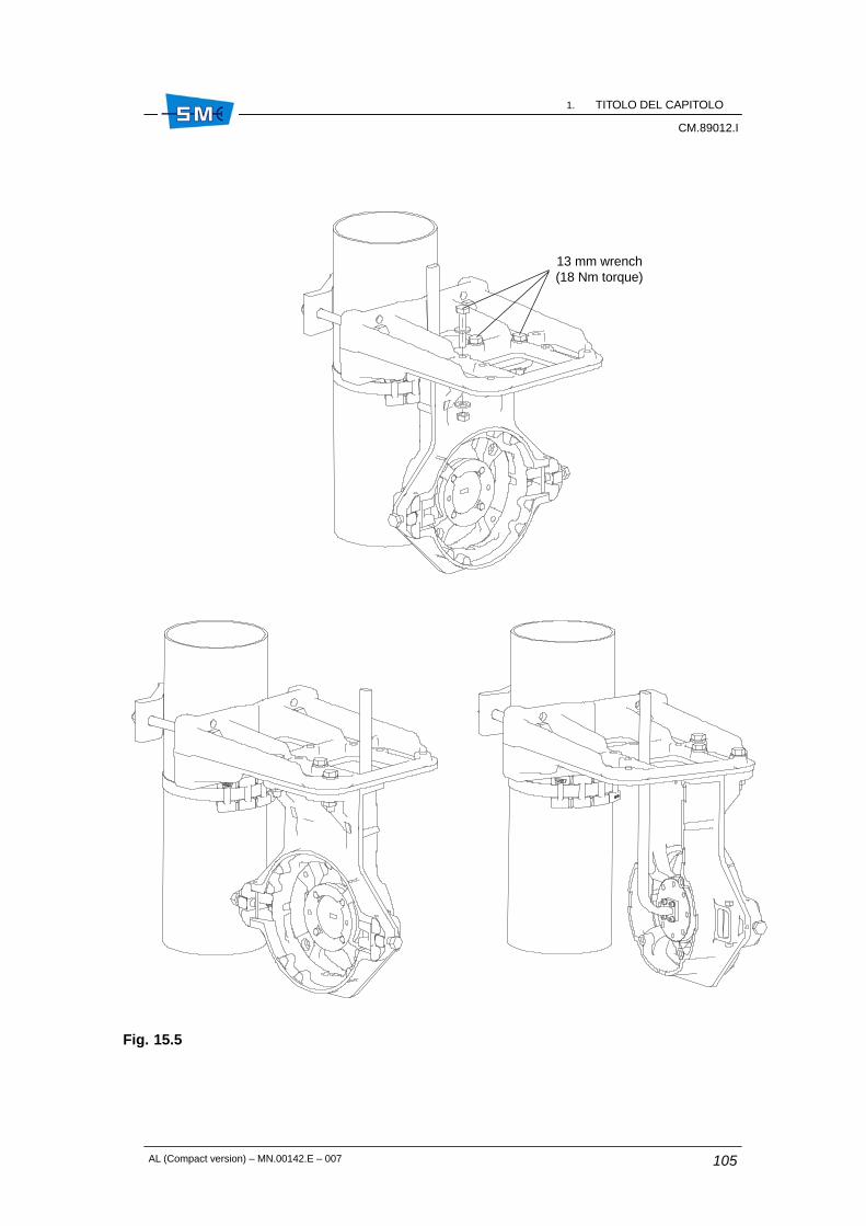
1. TITOLO DEL CAPITOLOCM.89012.I
CM.89012.I
AL (Compact version) – MN.00142.E – 007 105
Fig. 15.5
13 mm wrench(18 Nm torque)

1. TITOLO DEL CAPITOLOCM.89012.I
AL (Compact version) – MN.00142.E – 007106
Fig. 15.6 Band–it pole mounting

1. TITOLO DEL CAPITOLOCM.89012.I
CM.89012.I
AL (Compact version) – MN.00142.E – 007 107
Fig. 15.7
Use 13 mm wrench(18 Nm torque)
Reference toothReference tooth
Hybrid with ODU fastlocking mechanism
1
1
RT1 RT2
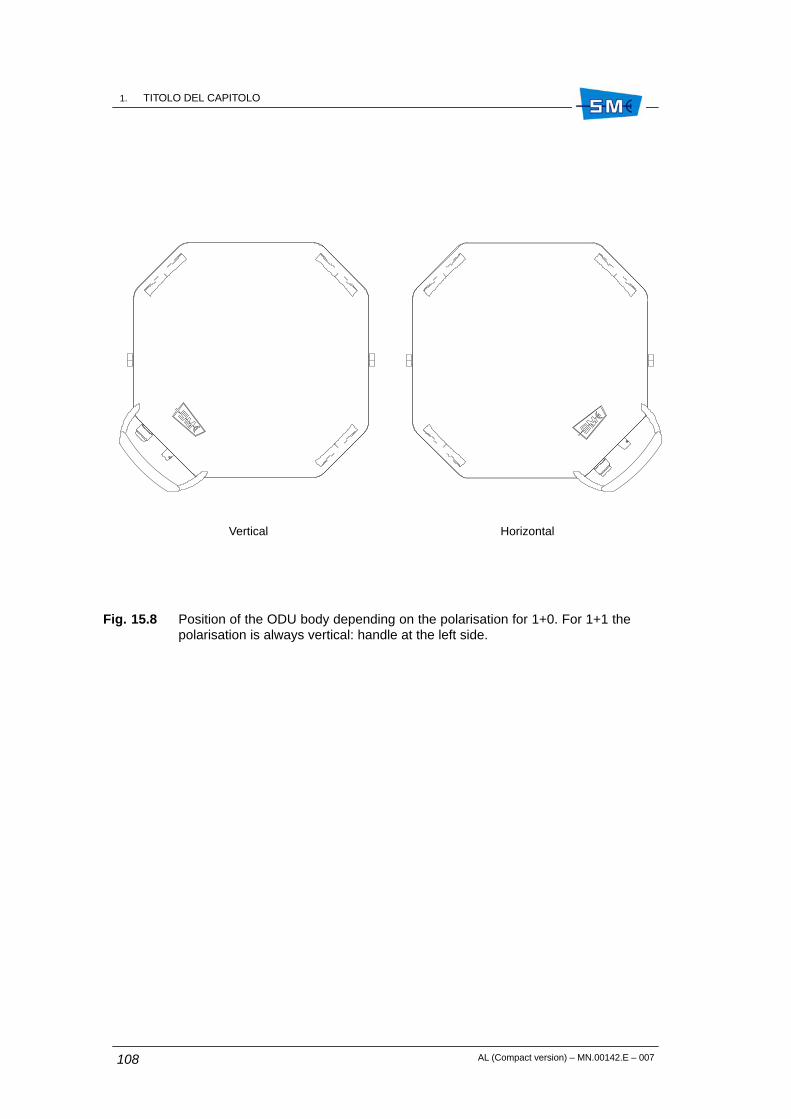
1. TITOLO DEL CAPITOLOCM.89012.I
AL (Compact version) – MN.00142.E – 007108
Fig. 15.8 Position of the ODU body depending on the polarisation for 1+0. For 1+1 thepolarisation is always vertical: handle at the left side.
Vertical Horizontal

1. TITOLO DEL CAPITOLOCM.89012.I
CM.89012.I
AL (Compact version) – MN.00142.E – 007 109
Fig. 15.9 ODU body reference tooth
”N”
”BNC”
Ground bolt
ODU side flange
Reference tooth
O–ring
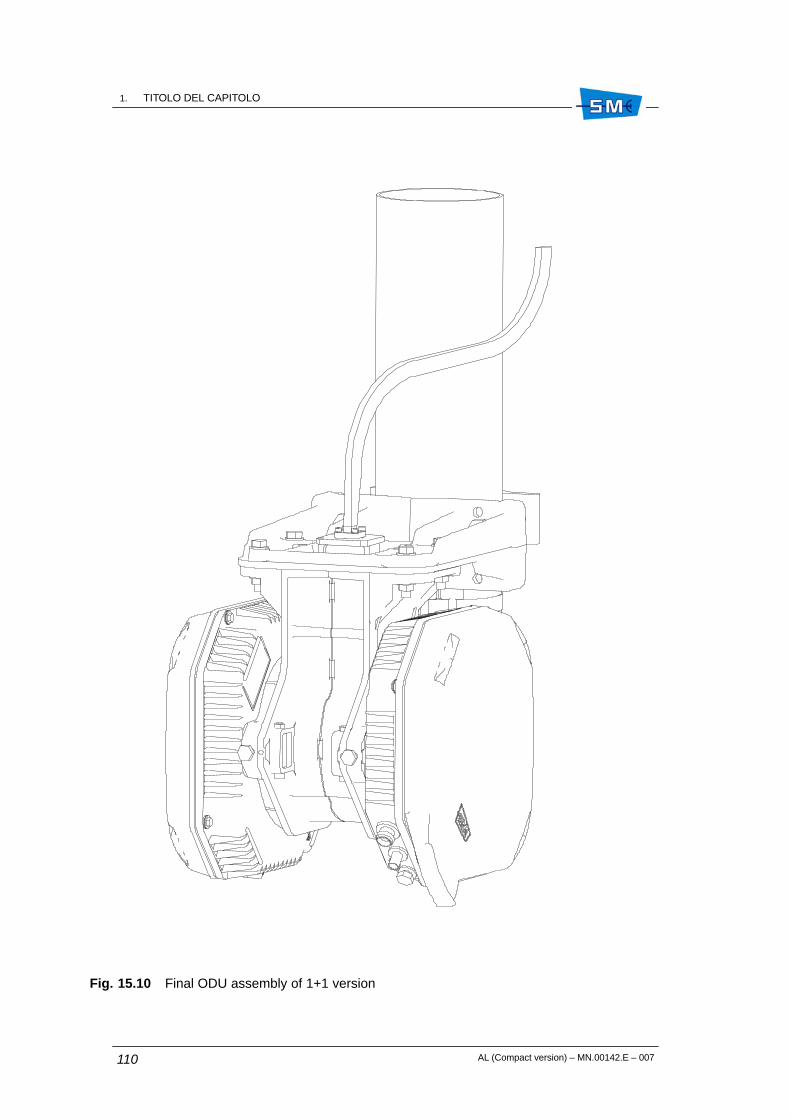
1. TITOLO DEL CAPITOLOCM.89012.I
AL (Compact version) – MN.00142.E – 007110
Fig. 15.10 Final ODU assembly of 1+1 version

1. TITOLO DEL CAPITOLOCM.89012.I
CM.89012.I
AL (Compact version) – MN.00142.E – 007 111
Fig. 15.11 ODU grounding
1
2
4
3
5
1. Bolt
2. Spring washer
3. Flat washer
4. Earth cable collar
5. Flat washer
13 mm torque wrench(6 Nm torque)

1. TITOLO DEL CAPITOLOCM.89012.I
AL (Compact version) – MN.00142.E – 007112

AL (Compact version) – MN.00142.E – 007 113
16. INSTALLATION ONTO THE WALLOF THE ODU WITH SEPARATEDANTENNA
16.1 INSTALLATION KIT
Following installation kits are supplied with the equipment depending on different versions:
• 1+0 version
– wall supporting plate with additional contact surface extension plates (seeFig. 16.1)
– antenna side flange, variable as function of RF frequency (see Fig. 16.2)
– support with ODU fast locking mechanism (see Fig. 16.2)
– flexible waveguide trunk for connection to antenna (optional) (see Fig. 16.2)
– kit for ground connection making part of ODU
• 1+1 version
– supporting plate with additional contact surface extension tools (see Fig. 16.1)
– hybrid with ODU fast locking mechanism (see Fig. 16.4)
– flexible waveguide trunk for connection to antenna (optional (see Fig. 16.2)
– kit for ground connection making part of the two ODUs.
ÓÓÓÓÓÓÓÓÓÓÓÓÓÓÓÓÓÓÓÓÓÓÓÓÓÓÓÓÓÓÓÓÓÓÓÓ
16

1. TITOLO DEL CAPITOLOCM.89012.I
AL (Compact version) – MN.00142.E – 007114
16.2 REQUIRED TOOLS FOR MOUNTING (NOT SUPPLIED)
• N.2 13mm torque wrench
• N.1 15 mm torque wrench
• N.1 17 mm torque wrench
• N.1 3 mm Allen wrench
• N.1 2.5 mm Allen wrench
16.3 INSTALLATION PROCEDURE
Installation procedure proceeds according to the following steps:
• Version 1+0: installation onto the wall of the supporting plate
• Version 1+1: installation onto the wall of the supporting plate
• Installation of the ODU (common to both 1+0 and 1+1 version)
• ODU grounding
1+0 version – Installation onto the wall of the supporting plate
Fig. 16.1 – Fix on the supporting plate the two supplied extension plates to increase the wallcontact surface.
Fig. 16.1 – Secure the supporting plate on the wall using the more suitable screws.
Fig. 16.2 – Fix the flexible waveguide to the antenna side flange. Four fixing screws are availablethe dimensions of which depend on the waveguide type. Tighten progressively and alternativelythe four screws with the following torque:
Tab. 16.1
Frequencies Screw Tool Torque
from 18 to 38 GHz Allen screw M3 Allen key 2.5 mm 1 Nm
up to 15 GHz Allen screw M4 Allen key 3 mm 2 Nm
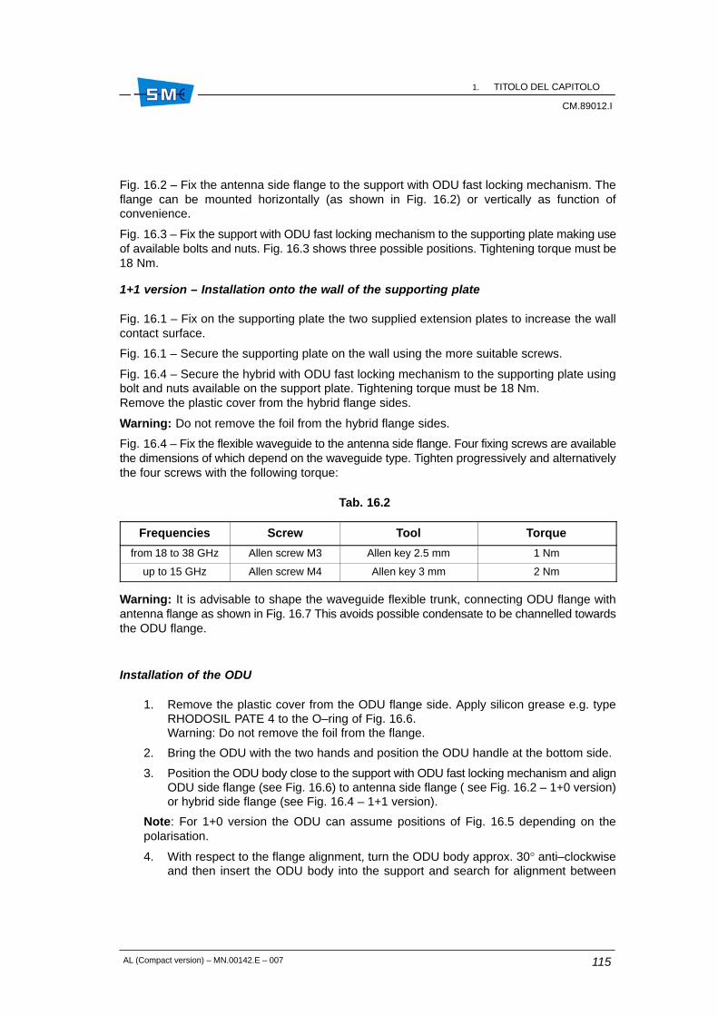
1. TITOLO DEL CAPITOLOCM.89012.I
CM.89012.I
AL (Compact version) – MN.00142.E – 007 115
Fig. 16.2 – Fix the antenna side flange to the support with ODU fast locking mechanism. Theflange can be mounted horizontally (as shown in Fig. 16.2) or vertically as function ofconvenience.
Fig. 16.3 – Fix the support with ODU fast locking mechanism to the supporting plate making useof available bolts and nuts. Fig. 16.3 shows three possible positions. Tightening torque must be18 Nm.
1+1 version – Installation onto the wall of the supporting plate
Fig. 16.1 – Fix on the supporting plate the two supplied extension plates to increase the wallcontact surface.
Fig. 16.1 – Secure the supporting plate on the wall using the more suitable screws.
Fig. 16.4 – Secure the hybrid with ODU fast locking mechanism to the supporting plate usingbolt and nuts available on the support plate. Tightening torque must be 18 Nm. Remove the plastic cover from the hybrid flange sides.
Warning: Do not remove the foil from the hybrid flange sides.
Fig. 16.4 – Fix the flexible waveguide to the antenna side flange. Four fixing screws are availablethe dimensions of which depend on the waveguide type. Tighten progressively and alternativelythe four screws with the following torque:
Tab. 16.2
Frequencies Screw Tool Torque
from 18 to 38 GHz Allen screw M3 Allen key 2.5 mm 1 Nm
up to 15 GHz Allen screw M4 Allen key 3 mm 2 Nm
Warning: It is advisable to shape the waveguide flexible trunk, connecting ODU flange withantenna flange as shown in Fig. 16.7 This avoids possible condensate to be channelled towardsthe ODU flange.
Installation of the ODU
1. Remove the plastic cover from the ODU flange side. Apply silicon grease e.g. typeRHODOSIL PATE 4 to the O–ring of Fig. 16.6.Warning: Do not remove the foil from the flange.
2. Bring the ODU with the two hands and position the ODU handle at the bottom side.
3. Position the ODU body close to the support with ODU fast locking mechanism and alignODU side flange (see Fig. 16.6) to antenna side flange ( see Fig. 16.2 – 1+0 version)or hybrid side flange (see Fig. 16.4 – 1+1 version).
Note: For 1+0 version the ODU can assume positions of Fig. 16.5 depending on thepolarisation.
4. With respect to the flange alignment, turn the ODU body approx. 30° anti–clockwiseand then insert the ODU body into the support and search for alignment between

1. TITOLO DEL CAPITOLOCM.89012.I
AL (Compact version) – MN.00142.E – 007116
reference tooth on the support (see Fig. 16.2 – 1+0 version or Fig. 16.4 – 1+1 version)and ODU body reference tooth (see detail Fig. 16.6)
5. When alignment is achieved, turn the ODU body clockwise until “clack” is heard andthe ODU rotation stops.
6. Secure ODU body on the support by tightening bolts (1) (see Fig. 16.2 – 1+0 versionor Fig. 16.4 – 1+1 version). Tightening torque must be 6 Nm.
Final assembly of 1+1 version is shown in Fig. 16.7.
16.4 GROUNDING
The ODU must be connected to ground making reference to details of Fig. 16.8.

1. TITOLO DEL CAPITOLOCM.89012.I
CM.89012.I
AL (Compact version) – MN.00142.E – 007 117
Fig. 16.1 Wall supporting plate
Extension plate
Supporting plate
M8 bolt and nut
13 mm wrench

1. TITOLO DEL CAPITOLOCM.89012.I
AL (Compact version) – MN.00142.E – 007118
Fig. 16.2 Support with ODU fast locking mechanism
Flexible waveguide trunk
Antenna side flange
Support with ODU fastlocking mechanism
Reference tooth
Position of antennaside flange
Reference tooth
1
1
13 mm wrench 6 Nm torque
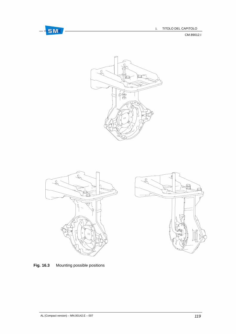
1. TITOLO DEL CAPITOLOCM.89012.I
CM.89012.I
AL (Compact version) – MN.00142.E – 007 119
Fig. 16.3 Mounting possible positions

1. TITOLO DEL CAPITOLOCM.89012.I
AL (Compact version) – MN.00142.E – 007120
Fig. 16.4
Use 13 mm wrench(18 Nm torque)
Reference toothReference tooth
Hybrid with ODU fastlocking mechanism
1
1
RT1 RT2

1. TITOLO DEL CAPITOLOCM.89012.I
CM.89012.I
AL (Compact version) – MN.00142.E – 007 121
Fig. 16.5 Position of the ODU body depending on the polarisation for 1+0. For 1+1 thepolarisation is always vertical: handle at the left side.
Vertical Horizontal

1. TITOLO DEL CAPITOLOCM.89012.I
AL (Compact version) – MN.00142.E – 007122
Fig. 16.6 ODU body reference tooth
”N”
”BNC”
Ground bolt
ODU side flange
Reference tooth
O–ring

1. TITOLO DEL CAPITOLOCM.89012.I
CM.89012.I
AL (Compact version) – MN.00142.E – 007 123
Fig. 16.7 Final ODU assembly of 1+1 version

1. TITOLO DEL CAPITOLOCM.89012.I
AL (Compact version) – MN.00142.E – 007124
Fig. 16.8 ODU grounding
1
2
4
3
5
1. Bolt
2. Spring washer
3. Flat washer
4. Earth cable collar
5. Flat washer

AL (Compact version) – MN.00142.E – 007 125
17. INSTALLATION ONTO THE POLE OFTHE ODU WITH INTEGRATEDANTENNA (KIT V52191, V52192)
17.1 FOREWORD
The installation onto the pole of the ODU with integrated antenna concerns both 1+0 and 1+1versions.
17.2 INSTALLATION KIT
Following installation kits are supplied with the equipment depending on different versions:
1+0 version
• 60 to 114 mm pole mounting kit consisting of:
– centering ring and relevant screws (see Fig. 17.1)
– antislide strip (see Fig. 17.2)
– pole support system and pole fixing brackets (see Fig. 17.3)
– ODU with O–ring and devices for ground connection
1+1 version
• pole mounting kit from 60 to 114 mm for 1+1 consisting of:
– centering ring and relevant screws (see Fig. 17.1)
– antislide strip (see Fig. 17.2)
– pole support system and pole fixing brackets (see Fig. 17.3)
ÓÓÓÓÓÓÓÓÓÓÓÓÓÓÓÓÓÓÓÓÓÓÓÓÓÓÓÓÓÓÓÓÓÓÓÓ
17

1. TITOLO DEL CAPITOLOCM.89012.I
AL (Compact version) – MN.00142.E – 007126
• hybrid mechanical body (see Fig. 17.12)
• polarization twist disk (see Fig. 17.13)
• 2 ODUs with O–rings and devices for ground connection
17.3 REQUIRED TOOLS FOR MOUNTING (NOT SUPPLIED)
• N.2 13 mm torque wrench
• N.1 15 mm torque wrench
• N.1 17 mm torque wrench
• N.1 3 mm Allen wrench
• N.1 2.5 mm Allen wrench
17.4 INSTALLATION PROCEDURE
Installation procedure proceeds according with the following steps:
1+0 version
1. installation onto the pole of the support system
2. installation of the antenna
3. installation of ODU
4. antenna aiming
5. ODU grounding
1+1 version
1. installation onto the pole of the support system
2. installation of the antenna
3. installation of hybrid circuit
4. installation of the two ODUs
5. antenna aiming
6. ODU grounding

1. TITOLO DEL CAPITOLOCM.89012.I
CM.89012.I
AL (Compact version) – MN.00142.E – 007 127
17.4.1 Installation onto the pole of the support system and the antenna
Fig. 17.1 – Set the antenna in such a position as to be able to operate on its rear side. Locatethe five threaded holes around antenna flange. Mount centering ring onto antenna flange andtight it with 3 calibrated bolts.Caution: centering ring should be mounted so that the screws do not stick out.
Define if the antenna will be mounted with vertical or horizontal polarization. Check that freedrain holes stay at bottom side. Mount bolt type M10x30, in position A leaving it loose of 2 cmapprox. With horizontal polarization mount bolt type M10x30 in position D, leaving it loose of2 cm approx.
Fig. 17.2 – Mount antislide strip onto the pole. Place blocks as in Fig. 17.2 following antennaaiming direction. Tighten the strip with screwdriver.
Fig. 17.3 – Mount pole supporting system with relevant pole fixing brackets following antennaaiming direction as indicated by arrow. Antislide strip should result at the center of supportingplate. Supporting system should lean against antislide clamp with the tooth as in Fig. 17.4.Position the antenna in such a way that bolt in position A or D of Fig. 17.1 cross through holeE of Fig. 17.5. Secure the support system to the pole by means of the pole fixing brackets andrelevant fixing bolts.
Fig. 17.6 – Rotate the antenna body until the remainder three antenna holes coincide with thethree support holes. Secure the antenna to the support by thightening the relevant passingthrough bolts.
17.4.2 Installation of ODU
1+0 version
1. Apply silicon grease e.g. RHODOSIL PATE 4” to the O–ring (4) of Fig. 17.9 byprotecting finger hands with gloves.
2. Bring the ODU with the two hands and position the ODU handle at the bottom side. TheODU handle can assume position of Fig. 17.7 depending on the polarization.
3. Position the ODU body near the support system and align ODU side flange to antennaside flange (see Fig. 17.8).With respect to the flange alignment, turn the ODU body approx. 30° anti–clockwiseand then insert the ODU body into the support and search for alignment betweenreference tooth on the support (see Fig. 17.8) and ODU body reference tooth (seedetail of Fig. 17.9).
4. When alignment is achieved, turn the ODU body clockwise until “clack” is heard andthe ODU rotation stops. Fig. 17.10 and Fig. 17.11 show ODU housing final position for vertical and horizontalpolarization respectively.
5. Secure ODU body on the support system by tightening bolts (1) of Fig. 17.8.

1. TITOLO DEL CAPITOLOCM.89012.I
AL (Compact version) – MN.00142.E – 007128
1+1 version
Fig. 17.12 – Apply silicon grease, type “RHODOSIL PATE 4” to O–rings (1). Insert O–rings (1) and (6) into twist polarization disk (2).
Vertical polarization
Fix the disk on hybrid flange placing marker (4), on disk, close to V mark.
Horizontal polarization
Fix the disk on hybrid flange placing reference (4), on disk, close to H mark.
Caution: Twist disk has two planes. Take care of position marker (4) on twist disk. The positionof marker (4) plane should be in contact to hybrid like in figure. Tighten progressively andalternatively four screws (7) with four spring washers (8) with the following torque:
Tab. 17.1
Frequencies Screw Tool Torque
from 18 to 38 GHz Allen screw M3 Allen key 2.5 mm 1 Nm
up to 15 GHz Allen screw M4 Allen key 3 mm 2 Nm
Fig. 17.13 – Fix hybrid to support system with four bolts (1) taking care of RT1/RT2 positionshown by labels of Fig. 17.13. Tighten progressively and alternatively four bolts (1).
17.4.3 ODU installation
The installation procedure of the two ODUs is the same.
1. Apply silicon grease e.g. RHODOSIL PATE 4” to the O–ring (4) of the Fig. 17.9 byprotecting finger hands with gloves.
2. Bring the ODU with the two hands and position the ODU handle at the bottom side. For1+0 the ODU can assume position of Fig. 17.7 depending on the polarisation. For 1+1 the handle ODU position is always placed at the right side (horizontalpolarization).
3. Position the ODU body near the support system and align ODU side flange to antennaside flange (see Fig. 17.8). With respect to the flange alignment, turn the ODU bodyapprox. 30° anti–clockwise and then insert the ODU body into the support and searchfor alignment between reference tooth on the support (see Fig. 17.8) and ODU bodyreference tooth (see detail of Fig. 17.9).
4. When alignment is achieved, turn the ODU body clockwise until “clack” is heard andthe ODU rotation stops. Fig. 17.10 and Fig. 17.11 show ODU housing final position for vertical and horizontalpolarization respectively for 1+0 version.Fig. 17.14 shows ODU housing final position for 1+1 version.
5. Secure ODU body on the support system by tightening bolts (1) of Fig. 17.8.
1. TITOLO DEL CAPITOLOCM.89012.I
CM.89012.I
AL (Compact version) – MN.00142.E – 007 129
17.5 ANTENNA AIMING
Antenna aiming for 1+0 version and 1+1 version is the same. The antenna aiming devices allowto perform the following adjustments with respect to the starting aiming position:
• ± 15° operating on the nut (3) shown in Fig. 17.15, onlyafter having loosen the nuts (7), (8), (9), (10) ofFig. 17.16.
• ± 15° operating on vertical adjustment worm screw (2)shown in Fig. 17.15 only after having loosen nuts (1),(2), (11) of Fig. 17.16 and (4) of Fig. 17.15.
For adjustment from 0° to +30° extract nut (1) Fig. 17.16and position it in hole (4), extract nut (2) Fig. 17.16 andposition it in hole (6). Operate on vertical adjustmentworm screw (2) after having loosen nuts (1), (2), (11) ofFig. 17.16 and (4) of Fig. 17.15.
For adjustment from 0° to –30° extract nut (1) ofFig. 17.16 and position it in hole (3), extract nut (2) ofFig. 17.16 and position it in hole (5). Operate on verticaladjustment worm screw (2) after having loosen nuts (1),(2), (11) of Fig. 17.16 and (4) of Fig. 17.15.
For vertical adjustment some markers, every 10°, are available on support. The bigger markergives 0° starting aiming position. Once the optimum aiming position is obtained, tighten firmlythe four nuts (1), (2), (11) of Fig. 17.16 and (4) of Fig. 17.15 for vertical adjustment and the fournuts (7), (8), (9), (10) of Fig. 17.16 for horizontal adjustment. Tighten with 15 mm wrench and32 Nm torque.
17.6 GROUNDING
See Fig. 17.17.
On ODU grounding can be connected with the available bolt spring washer and flat washers asshown.
Horizontal
vertical

1. TITOLO DEL CAPITOLOCM.89012.I
AL (Compact version) – MN.00142.E – 007130
Fig. 17.1
A
B C
D D
A B
C
A
B
C1
2
3
Horizontal polarizationVertical polarization
1. Antenna
2. Calibrated Allen screw
3. Centering ring
3 mm Allen key2,5 Nm torque

1. TITOLO DEL CAPITOLOCM.89012.I
CM.89012.I
AL (Compact version) – MN.00142.E – 007 131
Fig. 17.2 Antislide strip
1
2
1. Steel belt
2. Plastic blocks

1. TITOLO DEL CAPITOLOCM.89012.I
AL (Compact version) – MN.00142.E – 007132
Fig. 17.3 Support mount on pole
2
3Antenna aiming direction
15 mm wrench32 Nm torque
1
3
1
1. Pole fixing brackets
2. Tooth
3. Bolt
4. Pole support system
3
3 3
3

1. TITOLO DEL CAPITOLOCM.89012.I
CM.89012.I
AL (Compact version) – MN.00142.E – 007 133
Fig. 17.4
1
Antenna aiming direction
1. Tooth
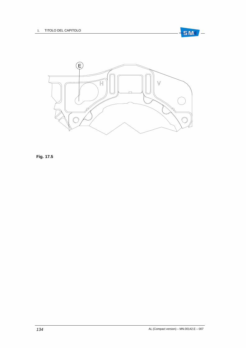
1. TITOLO DEL CAPITOLOCM.89012.I
AL (Compact version) – MN.00142.E – 007134
Fig. 17.5
E

1. TITOLO DEL CAPITOLOCM.89012.I
CM.89012.I
AL (Compact version) – MN.00142.E – 007 135
Fig. 17.6 Antenna installation on pole support
DA
B C
15 mm wrench32 Nm torque
A, B, C, D Bolt slots

1. TITOLO DEL CAPITOLOCM.89012.I
AL (Compact version) – MN.00142.E – 007136
Fig. 17.7 Position of the ODU handle depending on the polarisation for 1+0. For 1+1 the polarisation is always horizontal. Handle at the right side.
Vertical Horizontal

1. TITOLO DEL CAPITOLOCM.89012.I
CM.89012.I
AL (Compact version) – MN.00142.E – 007 137
Fig. 17.8 Support system for ODU housing and reference tooth in evidence
1
1
1
HH
HH
HH
HH
H: Reference tooth
13 mm wrench 6 Nm torque
1

1. TITOLO DEL CAPITOLOCM.89012.I
AL (Compact version) – MN.00142.E – 007138
Fig. 17.9 ODU body reference tooth
”N”
”BNC”
Ground bolt
ODU side flange
Reference tooth
O–ring

1. TITOLO DEL CAPITOLOCM.89012.I
CM.89012.I
AL (Compact version) – MN.00142.E – 007 139
Fig. 17.10 ODU housing final position for vertical polarization
30°

1. TITOLO DEL CAPITOLOCM.89012.I
AL (Compact version) – MN.00142.E – 007140
Fig. 17.11 ODU housing final position for horizontal polarization
30°
30°

1. TITOLO DEL CAPITOLOCM.89012.I
CM.89012.I
AL (Compact version) – MN.00142.E – 007 141
Fig. 17.12 Hybrid and twist disk
1. O–ring
2. Polarization twist disk
3. Hybrid mechanical body
4. Position marker of twist disk
5. Reference label for twist disk
6. O–ring
7. Allen screws
8. Spring washer
2
1
3
4
5
6
7
8

1. TITOLO DEL CAPITOLOCM.89012.I
AL (Compact version) – MN.00142.E – 007142
Fig. 17.13 Hybrid mount on pole support
21
1
1. Bolts
2. Spring washer
13 mm wrench 18 Nm torque
RT2
RT1

1. TITOLO DEL CAPITOLOCM.89012.I
CM.89012.I
AL (Compact version) – MN.00142.E – 007 143
Fig. 17.14 ODU housing final position for 1+1 version

1. TITOLO DEL CAPITOLOCM.89012.I
AL (Compact version) – MN.00142.E – 007144
Fig. 17.15 Vertical and horizontal adjustments
21
3
4
1. Marker
2. Vertical adjustment
3. Horizontal adjustment
4. Bolt
15 mm wrench 32 Nm torque
13 mm wrench
13 mm wrench

1. TITOLO DEL CAPITOLOCM.89012.I
CM.89012.I
AL (Compact version) – MN.00142.E – 007 145
Fig. 17.16 Antenna aiming block
2
1 3
5
4
69
10
87
1., 2., 3., 4. Horizontal aiming block bolts
5., 6., 7. Vertical aiming block bolts
8., 11. Threaded hole for vertical aiming up to –30°
9., 10. Threaded hole for vertical aiming up to +30°
15 mm wrench 32 Nm torque
11
15 mm wrench 32 Nm torque
15 mm wrench 32 Nm torque
15 mm wrench 32 Nm torque

1. TITOLO DEL CAPITOLOCM.89012.I
AL (Compact version) – MN.00142.E – 007146
Fig. 17.17 ODU grounding
1
2
4
3
5
1. Bolt
2. Spring washer
3. Flat washer
4. Earth cable collar
5. Flat washer

AL (Compact version) – MN.00142.E – 007 147
18. INSTALLATION ONTO THE POLE OFTHE ODU WITH INTEGRATEDANTENNA (KIT V32307, V32308,V32309)
18.1 FOREWORD
The description concerns pole mounting of ODU, in 1+0 and 1+1 version, using followinginstallation kits:
– for ODU with frequency from 10 to 13 GHz
– for ODU with frequency from 15 to 38 GHz
– for ODU with frequency from 7 to 8 GHz
Differences regard the dimensions and the presence of the centring ring (see Fig. 18.1):
– centring ring for antenna flange from 10 to 13 GHz
– centring ring for antenna flange from 15 to 38 GHz
– no centring ring (and relevant screws).
18.2 INSTALLATION KIT
Following installation kits are supplied with the equipment depending on different versions.
ÓÓÓÓÓÓÓÓÓÓÓÓÓÓÓÓÓÓÓÓÓÓÓÓÓÓÓÓÓÓÓÓÓÓÓÓ
18
V32307
V32308
V32309
V32307
V32308
V32309

1. TITOLO DEL CAPITOLOCM.89012.I
AL (Compact version) – MN.00142.E – 007148
1+0 version
• 60 to 129 mm pole mounting kit:
– centring ring and relevant screws
– pole support system plus antenna (already assembled) and pole fixing brackets
– 1+0 ODU support and relevant screws
– ODU with O–ring and devices for ground connection
1+1 version
• 60 to 129 mm pole mounting kit:
– centring ring and relevant screws
– pole support system plus antenna (already assembled) and pole fixing brackets
– 1+0 ODU support
– hybrid and relevant screws
– polarization twist disk and relevant screws
– 2 ODUs with O–rings and devices for ground connection.
18.3 REQUIRED TOOLS FOR MOUNTING (NOT SUPPLIED)
• N.1 2.5 mm Allen wrench
• N.1 3 mm Allen wrench
• N.1 5 mm Allen wrench
• N.1 6 mm Allen wrench
• N.1 13 mm spanner
• N.2 17 mm spanner.

1. TITOLO DEL CAPITOLOCM.89012.I
CM.89012.I
AL (Compact version) – MN.00142.E – 007 149
18.4 INSTALLATION PROCEDURE
Installation procedure is listed below:
1+0 version
1. antenna polarization
2. installation of the centring ring on the antenna
3. installation of 1+0 ODU support
4. installation onto the pole of the assembled structure
5. installation of ODU
6. antenna aiming
7. ODU grounding
1+1 version
1. antenna polarization
2. installation of the centring ring on the antenna
3. installation of 1+0 ODU support
4. installation onto the pole of the assembled structure
5. installation of hybrid
6. installation of ODUs
7. antenna aiming
8. ODU grounding.
18.5 1+0 MOUNTING PROCEDURES
18.5.1 Setting antenna polarization
Fig. 18.1 – Set the antenna in such a position to operate on its rear side. Locate the four 2.5 mmAllen screws around the antenna flange. Unscrew them (use 2.5 mm Allen wrench) and positionthe antenna flange according on: horizontal wave guide –> vertical polarization, vertical waveguide –> horizontal polarization. Screw again the four Allen screws (torque = 1Nm).

1. TITOLO DEL CAPITOLOCM.89012.I
AL (Compact version) – MN.00142.E – 007150
18.5.2 Installation of the centring ring on the antenna
Fig. 18.1 – Set the antenna in such a position to operate on its rear side. Locate the three holesaround the antenna flange. Mount the centring ring onto antenna flange and tight it with the 3Allen screws M4 (use 3mm Allen wrench, torque = 2Nm) .
18.5.3 Installation of 1+0 ODU support
Fig. 18.1 – Mount the support onto assembled structure (pole support system plus antenna)using the four 6 mm Allen screws (use 6 mm Allen wrench, torque = 18Nm). Two of the fourscrews, diagonally opposed, must be mounted with the two bushes around.
18.5.4 Installation onto the pole of the assembled structure
Fig. 18.1 – Mount the assembled structure on the pole using the two pole fixing brackets andthe four 17 mm screws (use 17 mm spanner, torque = 13Nm); the heads of the screws areinserted on the antenna side, the four nuts and the springs between nut and brackets areinserted on bracket side.
18.5.5 Installation of ODU (on 1+0 support)
Fig. 18.2 – Apply silicon grease (e.g. RHODOSIL PATE 4”) on the O–ring by protecting fingerswith gloves.
Fig. 18.3 – Bring the ODU with the two hands and position the ODU handle at the bottom side.The handle can assume the positions shown in the figure depending on the polarization. Positionthe ODU body near the support and align the wave guide of the ODU to the Wave guide of theantenna: respect to the position of wave guide alignment, turn the ODU body approx. 30°counter–clockwise and then insert the ODU body into the support and search for matchingbetween reference tooth on the support (see Fig. 18.4) and reference tooth on the ODU body.
Fig. 18.5 – When alignment of the references teeth is achieved, turn the ODU body clockwiseuntil “clack” is heard and rotation is stopped. In figure are shown ODU final position for bothpolarizations.
Fig. 18.4 – When ODU positioning is over, secure ODU body on the support by tightening bolts(use 17mm spanner, torque = 6Nm).

1. TITOLO DEL CAPITOLOCM.89012.I
CM.89012.I
AL (Compact version) – MN.00142.E – 007 151
18.5.6 Antenna aiming
Antenna aiming procedure for 1+0 version or 1+1 version is the same. Horizontal aiming: ±5° operating on the 17 mm nut shown in Fig. 18.6 with a 17 mm spanner,only after having loosen the two 17 mm nut on the pivot.Vertical aiming: ±20° operating on the 13 mm nut shown in Fig. 18.6 with a 13 mm spanner, onlyafter having loosen the three 13 mm nut on the pole support.
Once optimum position is obtained, tighten firmly all the nuts previously loosen.
18.5.7 ODU grounding
ODU grounding is achieved with:
• M8 screw without washers
• M6 screw with washer
as shown in Fig. 18.7.
18.6 1+1 MOUNTING PROCEDURES
In further page are explained all the mounting step not already discussed in “1+0 mountingprocedures”
18.6.1 Installation of Hybrid
Fig. 18.8 – The polarization twist disk must be always fixed on hybrid flange. Apply silicon grease(e.g. RHODOSIL PATE 4”) on the O–rings by protecting fingers with gloves. Bring thepolarization twist disk with the position marker down. Insert the O–ring into polarization twistdisk.Vertical polarization: fix the twist disk on hybrid flange placing the marker of the disk towardsV mark.Horizontal polarization: fix the twist disk on hybrid flange placing the marker of the disk towardsH mark.
Tighten progressively and alternatively the four screws and spring washer with following torque:
Tab. 18.1
Frequencies Screw Tool Torque
from 18 to 38 GHz Allen screw M3 Allen key 2.5 mm 1 Nm
up to 15 GHz Allen screw M4 Allen key 3 mm 2 Nm

1. TITOLO DEL CAPITOLOCM.89012.I
AL (Compact version) – MN.00142.E – 007152
Fig. 18.9 – Fix hybrid body to 1+0 support with four 13 mm bolts (use 13 mm spanner, torque= 18 Nm), tighten progressively and alternatively the bolts.
18.6.2 Installation of ODUs (on hybrid for 1+1 version)
For both ODUs.
Fig. 18.2 – Apply silicon grease e.g. RHODOSIL PATE 4” to the O–ring by protecting fingerswith gloves.
Fig. 18.3 – Bring the ODU with the two hands and position the ODU handle at the bottom side.The handle can assume the positions shown in the figure depending on the polarization. Positionthe ODU body near the support and align the wave guide of the ODU to the wave guide of thehybrid: respect to the position of wave guide alignment, turn the ODU body approx. 30°counter–clockwise and then insert the ODU body into the support. For 1+1 system the handleof the ODU is always positioned on the right. The polarization twist disk on the hybrid matchesthe antenna polarization.
Fig. 18.10 – When alignment of the reference teeth is achieved, turn the ODU body clockwiseuntil “clack” is heard and the rotation stops. In figure are shown ODUs final position.
Fig. 18.4 – When ODU positioning is over, secure ODU body on the support by tightening bolts(use 17 mm spanner, torque = 6 Nm).
WARNING: Internal codes (e.g. installation items, antennas, PCB) are here reported only asexample. The Manufacturer reserves the right to change them without any previous advice.
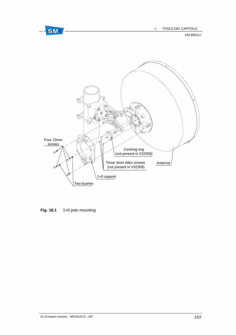
1. TITOLO DEL CAPITOLOCM.89012.I
CM.89012.I
AL (Compact version) – MN.00142.E – 007 153
Fig. 18.1 1+0 pole mounting
Four 13mmscrews
Two bushes
1+0 support
Three 3mm Allen screws (not present in V32309)
Centring ring(not present in V32309)
Antenna
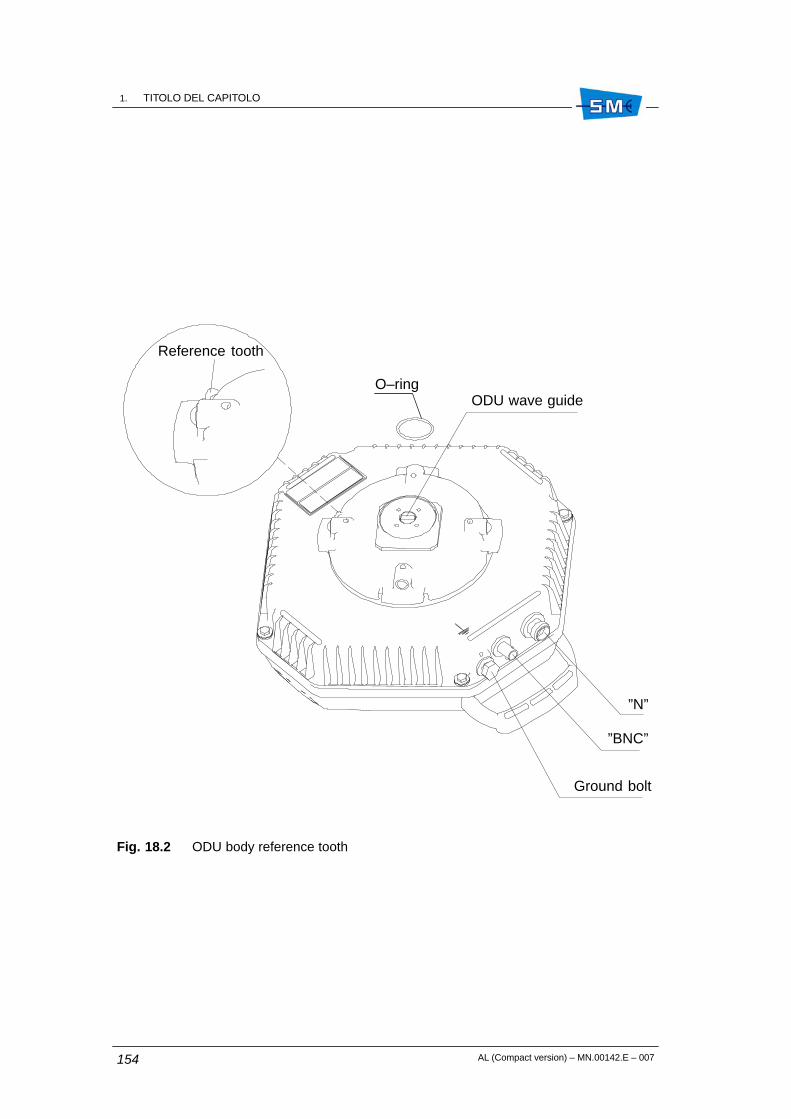
1. TITOLO DEL CAPITOLOCM.89012.I
AL (Compact version) – MN.00142.E – 007154
Fig. 18.2 ODU body reference tooth
”N”
”BNC”
Ground bolt
ODU wave guide
Reference tooth
O–ring
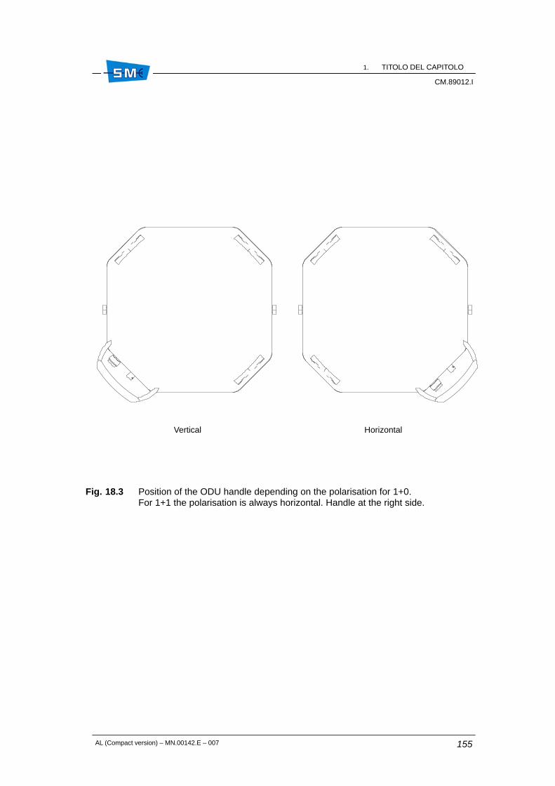
1. TITOLO DEL CAPITOLOCM.89012.I
CM.89012.I
AL (Compact version) – MN.00142.E – 007 155
Fig. 18.3 Position of the ODU handle depending on the polarisation for 1+0. For 1+1 the polarisation is always horizontal. Handle at the right side.
Vertical Horizontal

1. TITOLO DEL CAPITOLOCM.89012.I
AL (Compact version) – MN.00142.E – 007156
Fig. 18.4 1+0 support
1
1
2
23
1
1
3
4
5
4
5
1. 6 mm Allen screw
2. Bush (diagonally placed)
3. 17 mm Tightening bolts (max torque = 6 Nm)
4. Reference point for horizontal polarization
5. Reference point for vertical polarization

1. TITOLO DEL CAPITOLOCM.89012.I
CM.89012.I
AL (Compact version) – MN.00142.E – 007 157
Fig. 18.5 ODU housing final position for both polarization
1+0 ODU with handle on the right:horizontal polarization
1+0 ODU with handle on the right:vertical polarization
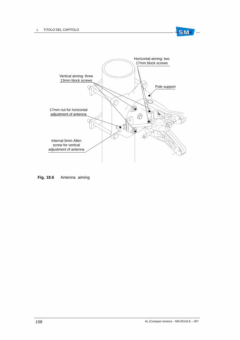
1. TITOLO DEL CAPITOLOCM.89012.I
AL (Compact version) – MN.00142.E – 007158
Fig. 18.6 Antenna aiming
Horizontal aiming: two17mm block screws
Vertical aiming: three13mm block screws
Pole support
17mm nut for horizontaladjustment of antenna
Internal 5mm Allenscrew for vertical
adjustment of antenna
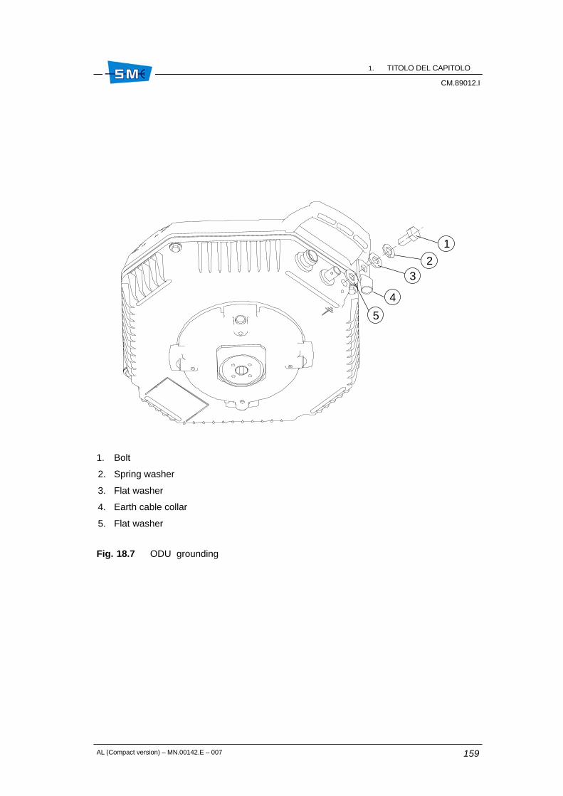
1. TITOLO DEL CAPITOLOCM.89012.I
CM.89012.I
AL (Compact version) – MN.00142.E – 007 159
Fig. 18.7 ODU grounding
1
2
4
3
5
1. Bolt
2. Spring washer
3. Flat washer
4. Earth cable collar
5. Flat washer

1. TITOLO DEL CAPITOLOCM.89012.I
AL (Compact version) – MN.00142.E – 007160
Fig. 18.8 Hybrid and twist disk
1. O–ring
2. Polarization twist disk
3. Hybrid mechanical body
4. Position marker of twist disk
5. Reference label for twist disk
6. O–ring
7. Allen screws
8. Spring washer
2
1
3
4
5
6
7
8

1. TITOLO DEL CAPITOLOCM.89012.I
CM.89012.I
AL (Compact version) – MN.00142.E – 007 161
Fig. 18.9 Hybrid installation

1. TITOLO DEL CAPITOLOCM.89012.I
AL (Compact version) – MN.00142.E – 007162
Fig. 18.10 1+1 ODUs installation

AL (Compact version) – MN.00142.E – 007 163
19. INSTALLATION ONTO THE POLE OFTHE 4 GHz ODU WITH SEPARATEDANTENNA (KIT V32323)
19.1 INSTALLATION KIT
1+0 version
• Anti–sliding bracket
• ODU pole support and relevant screws
1+0 version
• Anti–sliding bracket
• ODU pole support and relevant screws
• hybrid and relevant screws
• Hybrid–ODU connecting cables
19.2 REQUIRED TOOLS FOR MOUNTING (NOT SUPPLIED)
• N.2 13 mm spanner
• N.1 15 mm spanner
• N.1 17 mm spanner.
ÓÓÓÓÓÓÓÓÓÓÓÓÓÓÓÓÓÓÓÓÓÓÓÓÓÓÓÓÓÓÓÓÓÓÓÓ
19
1. TITOLO DEL CAPITOLOCM.89012.I
AL (Compact version) – MN.00142.E – 007164
19.3 INSTALLATION PROCEDURE
Installation procedure is listed below:
• 1+0/1+1 version: pole installation of the support
• 1+1 version: installation of the hybrid on the support
• installation of the ODU on the support
• ODU grounding and connection of the cables to the hybrid and antenna
1+0/1+1 version: pole installation of the support
Fig. 19.1 – Install anti–sliding device (1) around the pole. The position of the plastic blocksdepends on the position of the support (2) and of the relevant hooking pin (3).
Hook the support to the plastic blocks by means of the hooking pin. Insert to the four screws(4) in the relevant holes, set the two brackets (5) and clamp them around the pole tightening thefour nuts (6) (tightening torque = 32 Nm).
Cover the projecting bits of the screws using the relevant red covers (7).
The two holes (8) house the two tightening screws of the hybrid (only for 1+1 version).
1+1 version: hybrid installation on the support
Fig. 19.2 – Set the hybrid (1) on the support (2) in such a way that the connectors are downwardand that the holes on the lower side of the hybrid match with the corresponding holes (8) of theFig. 19.1.
Insert the two screws (3) (tightening torque = 7.3 Nm) and tighten the hybrid to the support.
ODU installation on the support
Locate the part of the support more suitable for the installation of the ODU: both the parts canbe used (1+0 version).
Fig. 19.2 – Locate the four slots (4) on the support (2).
Fig. 19.3 – Keeping the knob of the ODU1 downward, partially screw the two screws (2) into thetwo upper holes of the ODU, on N connector side.
Hook the heads of the two screws (2) of the Fig. 19.3 into the slots (4) of the Fig. 19.2.
Insert also the remaining screws (2) into the holes (3).
Tighten all the four screws (2) (tightening torque = 7.3 Nm).
Put the sun–cover (5) over the ODU (1) and fix it to the knob of the ODU by means of the suppliedstrip.
In case of 1+1 version, repeat the whole procedure for the second ODU.

1. TITOLO DEL CAPITOLOCM.89012.I
CM.89012.I
AL (Compact version) – MN.00142.E – 007 165
ODU grounding and connection of the cables to hybrid and antenna
Fig. 19.4 – Tighten the grounding cable of each ODU by means of grounding bolt (1) (tighteningtorque = 7.3 Nm) and the relevant washer. For the connection of the RF cable follow the labelon the bottom of the hybrid: ODU1 (RT1) is that connected to RIM1 of IDU, ODU 2 (RT2) is thatconnected to RIM2 of IDU.
Fig. 19.1 Pole installation of the support
4
4
4
4
8
2
3
6
7
67
5
5
1

1. TITOLO DEL CAPITOLOCM.89012.I
AL (Compact version) – MN.00142.E – 007166
Fig. 19.2 Installation of the hybrid on the pole support (only for 1+1 version)
2
3
1
4
4

1. TITOLO DEL CAPITOLOCM.89012.I
CM.89012.I
AL (Compact version) – MN.00142.E – 007 167
Fig. 19.3 Installation of the ODU on the support
5
231

1. TITOLO DEL CAPITOLOCM.89012.I
AL (Compact version) – MN.00142.E – 007168
Fig. 19.4 ODU grounding and connection of the cables to hybrid and antenna
1
1
RT2
RT1

AL (Compact version) – MN.00142.E – 007 169
ÓÓÓÓÓÓÓÓÓÓÓÓÓÓÓÓÓÓÓÓÓÓÓÓÓÓÓÓÓÓÓÓÓÓÓÓÓÓÓÓÓÓÓÓÓÓÓÓÓÓÓÓÓÓÓÓÓÓÓÓÓÓÓÓÓÓÓÓÓÓÓÓÓÓÓÓÓÓÓÓÓÓÓÓÓÓÓÓÓÓÓÓÓÓÓÓÓÓÓÓÓÓÓÓÓÓÓÓÓÓÓÓÓÓÓÓÓÓÓÓÓÓÓÓÓÓÓÓÓÓÓÓ
4Section
Line–up

1. TITOLO DEL CAPITOLOCM.89012.I
AL (Compact version) – MN.00142.E – 007170

AL (Compact version) – MN.00142.E – 007 171
20. LINE–UP OF THE RADIO HOP
20.1 LINE–UP OF THE RADIO HOP
The line–up consists of the following steps:
• on site radio terminal installation (perform user connections and ODU installation asdescribed in the relevant chapters)
• equipment switch–on (operate the ON/OFF switch on the IDU front)
• antenna alignment for maximum received RF signal level
• network element configuration
• check measurements.
20.1.1 Antenna alignment and received field measurement
Purpose of antenna alignment is to maximize the RF received signal level.
Proceed as follows:
• connect a multimeter to BNC connector on the ODU for AGC measurement
• adjust antenna pointing as soon as the maximum AGC voltage value is achieved.
The relationship between AGC voltage and received field is shown by Fig. 20.1.
The received field level has a tolerance of ±4 dB in the full temperature range.
ÓÓÓÓÓÓÓÓÓÓÓÓÓÓÓÓÓÓÓÓÓÓÓÓÓÓÓÓÓÓÓÓÓÓÓÓ
20
1. TITOLO DEL CAPITOLOCM.89012.I
AL (Compact version) – MN.00142.E – 007172
20.1.2 Network element configuration
A factory default address is assigned to each network element that must normally bereconfigured on site following the network administrator rules.
To this purpose it is required to connect the PC, where the SCT/LCT program has been installed,to the network interfaces.
This has to be done via USB or Ethernet cable.
Warning: the checks that follow require a good knowledge of the program use.
The description of each menu and relevant windows are given by the program itself as help online.
Run the program and perform the connection to equipment by choosing from menu “Option” theconnection made via USB cable.
Perform the login to the equipment by entering:
• Equipment IP address 7
• User ID (default: SYSTEM)
• Password: (default: SIAEMICR)
Proceed to program what above mentioned following this path:
• IP Address: select menu “Equipment” from the menu bar and then CommunicationSetup–>Port Configuration. Enter the required port addresses in the availablecommunication ports. Press ? for details.
• Routing Table and Default Gateway: select menu “Equipment” from the menu bar andthen Communication Setup–>Routing table: enter the routes or default gateway ifnecessary. Press ? for details.Warning: the routing policy depends on the routing type: manual IP/OSPF/IS–IS. Therelevant routing rules must be normally given by network administrator.
• Remote Element Table: select menu “Tools” from menu bar and then SubnetworkConfiguration Wizard. Station name and remote element table must be assignedfollowing description of the contextual help on–line (?).
• Agent IP Address: select menu “Equipment” and then “Properties”. Assign the addressin accordance to the address of the remote element you want to reach.
7. If the connection is made via USB cable, the IP address is automatically achieved.

1. TITOLO DEL CAPITOLOCM.89012.I
CM.89012.I
AL (Compact version) – MN.00142.E – 007 173
20.1.3 Radio checks
It is advisable to perform the following measurements to check the correct operation of the radiohop:
• Transmitted power
• Received power
• RF frequency
• BER measurement
All these checks make use of the SCT/LCT program.
• Transmitted power, received RF level, RF frequency
– Run SCT/LCT program and then perform the connection to the equipment youwant to check.
– Make double click on the select equipment until main RADIO PDH–AL window isshown.
– On top of the window Tx/Rx power and frequency values are displayed. In caseof Tx power and frequency setup proceed to Branch 1/2 and Power/Frequenciessubmenus.
• BER measurement
– Run SCT/LCT program and then perform the connection to the equipment youwant to check.
– Make double click on the selected equipment until main RADIO PDH–AL windowis shown.
– On the left side select BER1/2 measure.In alternative it is possible to use the PRBS function if one or 2 Mbit/s line is free.
– Perform the BER measurement and check that values comply with therequirements.

1. TITOLO DEL CAPITOLOCM.89012.I
AL (Compact version) – MN.00142.E – 007174
Fig. 20.1 Detected voltage versus Rf received signal
–100 –80 –60 –40 –20
3
2,25
1,5
0,75
0 dBm
V
–70 –50 –30
1,125
1,875
2,625

AL (Compact version) – MN.00142.E – 007 175
21. LINE–UP OF ETHERNET TRAFFIC(FOR IDU WITH V12252 ETHERNETMODULE ONLY)
21.1 GENERAL
This paragraph deals with line–up of V12252 Ethernet module with details of SCT/LCT programrelated only to Ethernet application.
Assuming that the radio link is already in service, with correct frequency, output power andcorrect antenna alignment, the line up procedure for different kinds of connection set up of aradio link AL, equipped with LIM Ethernet/2 Mbit/s module, is hereafter described:
1. Local Lan–1 port to remote Lan–1 port connection LAN per port, see Fig. 21.1
2. Local Lan–1 port to remote Lan–1 port connection with only VLANs
3. 3 to 1 port connections, see Fig. 21.13.
Settings here below are intended to be done both into local and remote radio equipment.
21.2 LOCAL LAN–1 PORT TO REMOTE LAN–1 PORT(TRANSPARENT CONNECTION LAN PER PORT)
Settings for Untagged and Tagged Traffic
Fig. 21.1 Local Lan–1 port to remote Lan–1 port connection
Radio
port 1
switch
Lan–1
Radio
port 1
switch
Lan–2
Lan–3
Nx2Mbit/s
Local
Lan–1
Lan–2
Lan–3
Nx2Mbit/s
Remote
ÓÓÓÓÓÓÓÓÓÓÓÓÓÓÓÓÓÓÓÓÓÓÓÓÓÓÓÓÓÓÓÓÓÓÓÓ
21

1. TITOLO DEL CAPITOLOCM.89012.I
AL (Compact version) – MN.00142.E – 007176
The line–up of Ethernet traffic is made with the help of SCT/LCT program.
Please refer to Fig. 21.2. First selection is Ethernet throughput and modulation scheme, in thisexample we select 16 Mbit/s and modulation 16QAM (max throughput and modulation schemedepend on terms of licence provided by Siae Microelettronica).
Select configuration 1+0 or 1+1 according system requirements. Inside LCT, select Tributarywindow. If 2 Mbit/s tributaries are needed, inside the Tributary window it is possible to activatea 2 Mbit/s input/output on the front panel. When the activation of required 2 Mbit/s tributariesis completed, all the others 2 Mbit/s streams are automatically used for the Ethernet traffic. Forinstance with a 8x2 Mbit/s capacity, if we use two 2 Mbit/s the capacity assigned to Ethernetcircuits is automatically set to 6x2 = 12 Mbit/s full duplex.
Fig. 21.2 Selection of Ethernet Throughput
See Fig. 21.3 for General settings for the switch. All the used ports must be Enabled, so enableLan–1 and Internal Port, see Fig. 21.4.
The other ports should be disabled. The correct cable crossover arrangement must be selectedtoo (see Fig. 21.4). At the end of Line–up, enable LLF if needed.
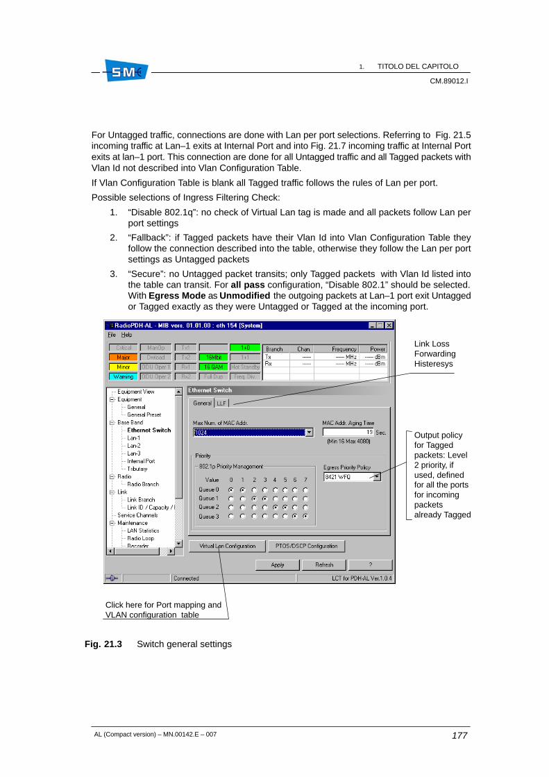
1. TITOLO DEL CAPITOLOCM.89012.I
CM.89012.I
AL (Compact version) – MN.00142.E – 007 177
For Untagged traffic, connections are done with Lan per port selections. Referring to Fig. 21.5incoming traffic at Lan–1 exits at Internal Port and into Fig. 21.7 incoming traffic at Internal Portexits at lan–1 port. This connection are done for all Untagged traffic and all Tagged packets withVlan Id not described into Vlan Configuration Table.
If Vlan Configuration Table is blank all Tagged traffic follows the rules of Lan per port.
Possible selections of Ingress Filtering Check:
1. “Disable 802.1q”: no check of Virtual Lan tag is made and all packets follow Lan perport settings
2. “Fallback”: if Tagged packets have their Vlan Id into Vlan Configuration Table theyfollow the connection described into the table, otherwise they follow the Lan per portsettings as Untagged packets
3. “Secure”: no Untagged packet transits; only Tagged packets with Vlan Id listed intothe table can transit. For all pass configuration, “Disable 802.1” should be selected.With Egress Mode as Unmodified the outgoing packets at Lan–1 port exit Untaggedor Tagged exactly as they were Untagged or Tagged at the incoming port.
Fig. 21.3 Switch general settings
Link LossForwardingHisteresys
Click here for Port mapping andVLAN configuration table
Output policyfor Taggedpackets: Level2 priority, ifused, definedfor all the portsfor incomingpacketsalready Tagged

1. TITOLO DEL CAPITOLOCM.89012.I
AL (Compact version) – MN.00142.E – 007178
Fig. 21.4 Lan–1 interface settings

1. TITOLO DEL CAPITOLOCM.89012.I
CM.89012.I
AL (Compact version) – MN.00142.E – 007 179
Fig. 21.5 Vlan settings for Lan–1

1. TITOLO DEL CAPITOLOCM.89012.I
AL (Compact version) – MN.00142.E – 007180
Fig. 21.6 Priority setting for Lan–1 and Internal Port
IncomingUntaggedpackets at
Lan–1 are sentinto output partqueue followingthis selection.
In this examplepackets areinserted into
queue 0.
With Priority disabled no check is done into 802.1p priority Tag. All types of packets go intoDefault Priority Queue.

1. TITOLO DEL CAPITOLOCM.89012.I
CM.89012.I
AL (Compact version) – MN.00142.E – 007 181
Fig. 21.7 Vlan settings for Internal Port
Fig. 21.8 Vlan Configuration Table

1. TITOLO DEL CAPITOLOCM.89012.I
AL (Compact version) – MN.00142.E – 007182
21.3 LOCAL LAN–1 PORT TO REMOTE LAN–1 PORT (WITHVLANs)
Settings are done to transfer only Tagged traffic within Vlans.
We want that Vlan 701, 702, 710 and 1, 2, 3 can pass into the radio link and all the other Taggedor Untagged packets should be blocked.
The line up of Ethernet module is made with the help of LCT/SCT program. Please refer toFig. 21.2. First selection is Ethernet throughput and modulation scheme, in this example weselect 16 Mbit/s and modulation 16QAM (max throughput and modulation scheme depends onterms of licence provided by Siae Microelettronica). Select configuration 1+0 or 1+1 accordingsystem requirements.
Inside LCT, select tributary window. If 2 Mbit/s tributaries are needed, inside the tributary windowit is possible to activate a 2 Mbit/s input/output on the front panel. When the activation of required2 Mbit/s tributaries is completed, all the others 2 Mbit/s streams are automatically used for theEthernet traffic. for instance with a 16 Mbit/s capacity if we use two 2 Mbit/s the capacityassigned to ethernet circuits is automatically set to 16–2x2 = 12 Mbit/s full duplex.
See Fig. 21.3 for general settings for the switch. All the used ports must be enabled, so enableLan–1 and Internal Port, see Fig. 21.4. The other ports should be disabled. The correct Cablecrossover arrangement must be selected too. Enable LLF if needed, only at the end of line up.
Vlan settings for Lan–1 and Internal Port should be like in Fig. 21.9 with Ingress Filtering Checkas “Secure” and Engress Mode as “Tagged”. With this setting only Tagged packets with VlanID listed into the Vlan Configuration Table can transit. All Untagged packets are blocked at theincoming port and outgoing Tagged packets don’t change.
A packet with Vlan ID XX can enter into the switch only if Incoming Port (Ingress port) is amember of the Vlan XX, same packet will exit only from ports (Engress Port) which are membersof Vlan XX. Vlan membership is described into Vlan Configuration Table. A port can be memberof no one, one or more Vlans. See Fig. 21.10 for Vlan Configuration Table settings for ourexample.

1. TITOLO DEL CAPITOLOCM.89012.I
CM.89012.I
AL (Compact version) – MN.00142.E – 007 183
Fig. 21.9 Virtual Lan input and output settings at Lan–1 port
Fig. 21.10 Vlan Configuration Table with some Vlans

1. TITOLO DEL CAPITOLOCM.89012.I
AL (Compact version) – MN.00142.E – 007184
Tagged incoming packet can be treated with FIFO policy or on the basis of their 802.1p prioritytag and ToS/DSCP value for IP packets. There are 4 queue at each output port. The decisionabout to which output queue to send a packet is defined into Ethernet switch window selectionsfor 802.1p tag. Into Ethernet switch window it is possible to select ToS/DSCP button to openwindow ToS/DSCP, in this window each incoming ToS/DSCP value is associated with an outputqueue so it is possible to change the priority of the incoming packet.
When no info on priority is available, the packet is sent to Default Priority Queue using FIFOpolicy.
Into Lan–1 window select Priority (802.1q), into priority box there are some selections: with“Disable” switch doesn’t look at priority tag; with “802.1p” switch looks at Tag 802.1p only; with“IpToS” for IP packets only switch looks to ToS/DSCP identifier (into IP frame) only; with “802.1p– IpToS” switch looks first to 802.1p tag and secondly to ToS/DSCP, see Fig. 21.12; with“IpToS–802.1p” switch looks first to ToS/DSCP and secondly to Tag 802.1p.
Note: with IpToS switch looks to IP packet and ToS/DSCP doesn’t matter if the packets aretagged with 802.1p or not.
In this example incoming tagged are tagged and it is necessary to transfer the packets with nochange so they must exit from output ports tagged, see Fig. 21.11 and Fig. 21.12.
Fig. 21.11 Add a new Vlan ID to Vlan Configuration Table with output tagged

1. TITOLO DEL CAPITOLOCM.89012.I
CM.89012.I
AL (Compact version) – MN.00142.E – 007 185
Fig. 21.12 Layer 2 and Layer 3 priority management
IncomingUntaggedpackets at
Lan–1 are sentinto output partqueue followingthis selection.
In this examplepackets areinserted into
queue 0.

1. TITOLO DEL CAPITOLOCM.89012.I
AL (Compact version) – MN.00142.E – 007186
21.4 3 TO 1 PORT CONNECTIONS
Fig. 21.13 3 to 1 port connections
ALradio
port 1
switch
Lan–1
ALradio
port 1
switch
Lan–2
Lan–3
Nx2Mbit/s
Local
Lan–1
Lan–2
Lan–3
Nx2Mbit/s
Remote
In this example 3 local port must communicate with corresponding remote ports. All the portsshare the same radio channel but traffic originated and directed to Lan1 should be keptseparated from traffic from Lan2 and Lan3 and viceversa.
Lan–1 to Lan–1 connection should transfer tagged packets with Vlan 1, 701, 760 and untaggedpackets. Unspecified tagged packets must be stopped. Lan–2 and Lan–3 have the samerequirements. For all connections IP packets with high priority TOS should transferred atminimum delay.
21.5 3 TO 1 PORT CONNECTIONS, SETTINGS FORUNTAGGED TRAFFIC
The line–up of Ethernet traffic is made with the help of LCT/SCT. Please refer to Fig. 21.1.
First selection is Ethernet throughput and modulation scheme, in this example we select 16Mbit/s and modulation 16QAM (max throughput and modulation scheme depend on terms oflicence provided by Siae Microelettronica). Select configuration 1+0 or 1+1 according systemrequirements.
Inside LCT, select Tributary window.
If 2 Mbit/s tributaries are needed, inside the tributary window it is possible to activate a 2 Mbit/sinput/output on the front panel. When the activation of required 2 Mbit/s tributaries is completed,all the others 2 Mbit/s streams are automatically used for the Ethernet traffic. For instance witha 8x2 Mbit/s capacity if we use two 2 Mbit/s the capacity assigned to Ethernet circuits isautomatically set to 6x2 = 12 Mbit/s full duplex.

1. TITOLO DEL CAPITOLOCM.89012.I
CM.89012.I
AL (Compact version) – MN.00142.E – 007 187
Vlan Configuration Table will be defined in order to group traffic from Lan–1, Lan–2, Lan–3 toPort1. All the used ports must be Enabled.
Untagged traffic transits only if the selection for Ingress Filtering Check is disabled at each inputport and a separated Vlan for Untagged traffic is set up for each port. See Fig. 21.3, Fig. 21.4,Fig. 21.13, Fig. 21.14 and Fig. 21.15.
Each port of the switch must be associated with a different Default VLAN ID in order to maintainthe traffic coming from different separated LANs, Lan–1 with default VID 3301, Lan–2 withdefault VID 3302, Lan–3 with default VID 3303, for Lan–1 see Fig. 21.15 and Fig. 21.16.
The correct Cable Crossover arrangement must be selected too.
Fig. 21.14 Input and output setting for VLANs at Lan–1 port

1. TITOLO DEL CAPITOLOCM.89012.I
AL (Compact version) – MN.00142.E – 007188
Fig. 21.15 Output port properties for VLAN 3301

1. TITOLO DEL CAPITOLOCM.89012.I
CM.89012.I
AL (Compact version) – MN.00142.E – 007 189
Fig. 21.16 Typology 3 to 1, Virtual Lan Configuration
Default VID assigned byuser to each port
Vlan 3301, 3302, 3303 are allowed to exit at Port1with tags (Tagged). Different default Tag’s allow to
keep separate the traffic from Lan1, Lan2 andLan3 exiting at Port 1. At the remote end the traffic
is split and forwarded from Port1 to Lan1, Lan 2and Lan3 without Tag to preserve the original
format.
With the above settings inside the VLAN configuration Table only Untagged traffic is forwardedaccross the bridge.
The same settings should be done inside the remote equipment. The above example showsthe Virtual Lan Configuration Table in case of a link carrying the traffic of 3 independent LAN’sconnected to Lan–1, Lan–2, Lan–3, which is split at the remote end among the outgoing Lan–1,Lan–2, Lan–3 ports, while using a common radio link.
To prioritize some IP packets with high ToS/DSCP value it is possible to open PToS/DSCPwindow from Ethernet switch window and select the values of ToS for which the packet is sentto high priority Queue, see Fig. 21.17.

1. TITOLO DEL CAPITOLOCM.89012.I
AL (Compact version) – MN.00142.E – 007190
Fig. 21.17 Output Queue selection on the basis of TOS/DSCP priority
TOS value description DSCP value description
Packetswith AF43
prioritylevel willgo into
Queue 3 atall ports
AF43 now goes to Queue 3, with thisbutton AF43 will go to Queue 2
21.6 3 TO 1 PORT CONNECTIONS, SETTINGS FOR TAGGEDAND UNTAGGED TRAFFIC
If we want VLAN with Tag 701, 702 and 703 to transit between Lan–1 and Port–1 it is necessaryto define Port 1 and Lan 1 as members of VLAN1, 701, 760 (see Fig. 21.18 for VLAN 701 anddo the same for VLAN1, 760).
The VLAN Configuration Table will look like Fig. 21.19.
For Lan–2 and Lan–3 we cannot use the same Vlan if we want to maintain traffic from Lan 1,2, 3 separated. We must change the number of incoming Vlan for instance of 1, 701, 760 use2001, 2701, 2760 for Lan–2 and 3001, 3701, 3760 for Lan–3. Connected equipment to Lan–2port should be reprogrammed to use Vlan 2001, 2701, 2760.
Connected equipment to Lan–3 port should be reprogrammed to use Vlan 3001, 3701, 3760.
To prioritize Ip packets with high ToS/DSCP value it is possible to open PToS/DSCP window fromEthernet switch window and select the values of ToS for which the packet is sent to high priorityQueue 3, see Fig. 21.17. The same should be done inside the remote equipment.

1. TITOLO DEL CAPITOLOCM.89012.I
CM.89012.I
AL (Compact version) – MN.00142.E – 007 191
Fig. 21.18 Output properties of VLAN 701

1. TITOLO DEL CAPITOLOCM.89012.I
AL (Compact version) – MN.00142.E – 007192
Fig. 21.19 Typology 3 to 1, Virtual Lan Configuration Table with Vlan
21.7 3 TO 1 CONNECTIONS: EXAMPLES OF PRIORITYMANAGEMENT
Example 1: To assign to Lan–1 and Lan–3 low priority and to Lan–2 high priority, while wantingTagged and Untagged to be treated in a fair manner on each queue do as follow: select PriorityDisable for Lan–1, Lan–2 and Lan–3; select Default Priority Queue equal to Queue 0 for lan–1and Lan–3 (see Fig. 21.6). Select Default Priority Queue equal to Queue 3 for Lan–2 (as inFig. 21.20).
Outgoing Untagged packets will take priority tag defined into input port, in this case 0. Taggedframes keep their tag.
Example 2: Wanting tagged frames to be treated according their actual priority and untaggedpackets with low priority, all inputs should be configured as in Fig. 21.21.
Layer 2 Priority assignment is not modified if inside the second folder of the Lan–X (1, 2, 3)configuration window Untagged Frame Egress Mode = Unmodified is selected as in Fig. 21.22.

1. TITOLO DEL CAPITOLOCM.89012.I
CM.89012.I
AL (Compact version) – MN.00142.E – 007 193
Fig. 21.20 Queue selection
Untagged packet arriving to Lan–2 are sent to output port Queues setting of thisfolder. In this example all incoming packets at Lan–2 are inserted into output
Queue 3 of output ports. Input priority: when Disable is not selected, Tagged frame are sent to queue0,1,2,3 to port destination priority value; when Disable is selected for this portswitch uses the Default Priority Queue for Tagged and Untagged frames, and
without really changing Tag into Incoming Tagged frames.

1. TITOLO DEL CAPITOLOCM.89012.I
AL (Compact version) – MN.00142.E – 007194
Fig. 21.21 Management of tagged frames according with their priority tag

1. TITOLO DEL CAPITOLOCM.89012.I
CM.89012.I
AL (Compact version) – MN.00142.E – 007 195
Fig. 21.22 Incoming packets at Lan–1 will exit to other ports unchanged according theirincoming status.

1. TITOLO DEL CAPITOLOCM.89012.I
AL (Compact version) – MN.00142.E – 007196

AL (Compact version) – MN.00142.E – 007 197
ÓÓÓÓÓÓÓÓÓÓÓÓÓÓÓÓÓÓÓÓÓÓÓÓÓÓÓÓÓÓÓÓÓÓÓÓÓÓÓÓÓÓÓÓÓÓÓÓÓÓÓÓÓÓÓÓÓÓÓÓÓÓÓÓÓÓÓÓÓÓÓÓÓÓÓÓÓÓÓÓÓÓÓÓÓÓÓÓÓÓÓÓÓÓÓÓÓÓÓÓÓÓÓÓÓÓÓÓÓÓÓÓÓÓÓÓÓÓÓÓÓÓÓÓÓÓÓÓÓÓÓÓ
5Section
Maintenance

1. TITOLO DEL CAPITOLOCM.89012.I
AL (Compact version) – MN.00142.E – 007198

AL (Compact version) – MN.00142.E – 007 199
22. PERIODICAL CHECKS
22.1 GENERAL
Periodical checks are used to check correct operation of the radio equipment without thepresence of any alarm condition.
The SCT/LCT programs running on the PC are used for the purpose.
22.2 CHECKS TO BE CARRIED OUT
The following checks must be carried out:
• check of the transmitted power;
• check of the received field strength (the reading must match the value resulting fromhop calculations);
• check of bit error rate and hop performances.
For checking procedures, please refer to SCT/LCT program and relevant help–on line.
ÓÓÓÓÓÓÓÓÓÓÓÓÓÓÓÓÓÓÓÓÓÓÓÓÓÓÓÓÓÓÓÓÓÓÓÓ
22

1. TITOLO DEL CAPITOLOCM.89012.I
AL (Compact version) – MN.00142.E – 007200

AL (Compact version) – MN.00142.E – 007 201
23. TROUBLESHOOTING
23.1 GENERAL
The AL equipment consists of the following replaceable parts:
• IDU
• ODU
Purpose of the troubleshooting is to pinpoint the faulty part and replace it with spare.
Warning: the replacement of a faulty IDU with spare causes the spare IDU to bere–programmed. To the purpose refer to chapter 19 for the relevant procedure.
23.2 TROUBLESHOOTING PROCEDURE
Troubleshooting starts as soon as one of the following alarm condition: IDU/ODU/REM isswitched ON on the IDU panel from (see Fig. 23.1) or alarm messages are displayed bymanagers SCT/LCT.
Two methods are used to troubleshoot the cause of fault:
• loop facilities
• alarm message processing using the manager SCT/LCT
ÓÓÓÓÓÓÓÓÓÓÓÓÓÓÓÓÓÓÓÓÓÓÓÓÓÓÓÓÓÓÓÓÓÓÓÓ
23

1. TITOLO DEL CAPITOLOCM.89012.I
AL (Compact version) – MN.00142.E – 007202
23.2.1 Loop facilities
The equipment is provided with different loops that help locate the faulty part.
Warning: the majority of loops causes the traffic to be lost.
The available loops are the following:
• local tributary loops: usually used to test the cables interfacing the equipmentupstreams
• remote tributary loops: usually used to test the two direction link performance makinguse of an unused 2 Mbit/s signal.
• baseband loop: it permits to test the LIM circuits
• IDU loop: it permits to test the complete IDU (optional)
• RF loop: it permits to test the complete radio terminal.
23.2.2 Alarm messages processing
When an alarm condition occurs, the equipment generates a number of alarm messages thatappear on the SCT windows ie: log history area and equipment view current alarm.
Investigation on the alarm message meaning permits to troubleshoot the faulty module.
Alarm message organisation
The alarms (traps) are organized as alarm grouping relevant to a specific functions performedby the equipment.
The alarm grouping is available only in the view current alarm submenu.
What follows is the list of the alarm grouping:
• COMMON – alarms which are not related to a specific part of the equipment butrelevant to the link as EOC radio link alarm or link telemetry fail. If these alarms are ONthe link is lost. Investigation must be made on a possible bad propagation or equipmentfailure. See the condition of the others alarm grouping.
• LIM – This grouping may generate alarms for the following causes:
– external fault: tributary loss signal
– LIM failure: i.e. multiplexer/demultiplexer failure or modulator/demodulator failure.
• RIM – This grouping may generate alarms for the following causes:
– external fault: demodulator fail alarm and local ODU alarm are generated whenthe ODU becomes faulty.
– RIM failure – power supply alarm along with cable short/open alarms ormodulator/demodulator alarms are activated.
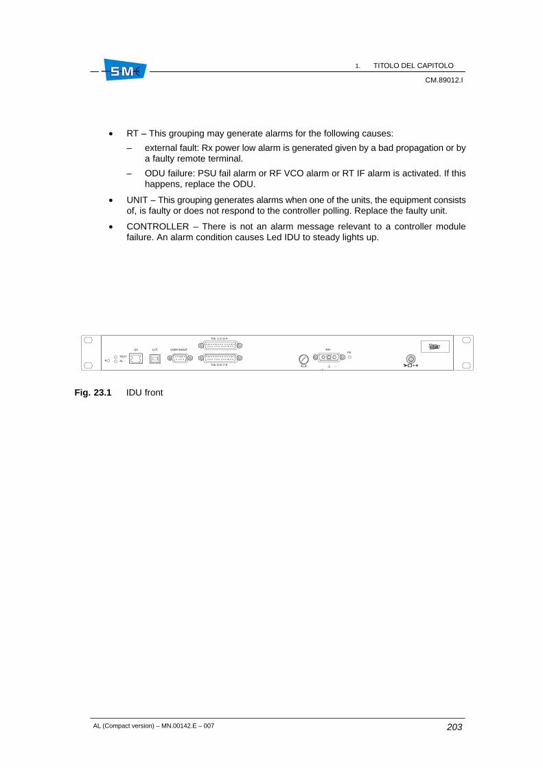
1. TITOLO DEL CAPITOLOCM.89012.I
CM.89012.I
AL (Compact version) – MN.00142.E – 007 203
• RT – This grouping may generate alarms for the following causes:
– external fault: Rx power low alarm is generated given by a bad propagation or bya faulty remote terminal.
– ODU failure: PSU fail alarm or RF VCO alarm or RT IF alarm is activated. If thishappens, replace the ODU.
• UNIT – This grouping generates alarms when one of the units, the equipment consistsof, is faulty or does not respond to the controller polling. Replace the faulty unit.
• CONTROLLER – There is not an alarm message relevant to a controller modulefailure. An alarm condition causes Led IDU to steady lights up.
Fig. 23.1 IDU front
48V
+ –
Trib. 1–2–3–4
Trib. 5–6–7–8
PSLCTQ3 USER IN/OUT
RTEST
AL

1. TITOLO DEL CAPITOLOCM.89012.I
AL (Compact version) – MN.00142.E – 007204

AL (Compact version) – MN.00142.E – 007 205
24. EQUIPMENT CONFIGURATIONUPLOAD/SAVE/DOWNLOAD.PARAMETER MODIFICATION ANDCREATION OF VIRTUALCONFIGURATIONS.
24.1 SCOPE
This chapter describes the procedure to create configuration files.
Equipment configuration files must be used in case of replacing a faulty IDU with a spare. Tothis purpose it is necessary to upload, from each network element, equipment configurationsand save them on three configuration files.
It is advisable to do it upon the first installation. Configuration file download on the spareCONTROLLER permits to restore previous operating condition. It is also possible to createvirtual configuration without being connected to equipment.
24.2 PROCEDURE
To configure the spare IDU the following must be uploaded/saved on the file/downloaded:
• General equipment configuration
• Addresses and routing table
• Remote element table
To do it, run the SCT/LCT program (see relevant documentation available on line) until“Subnetwork Craft Terminal” application window is displayed.
ÓÓÓÓÓÓÓÓÓÓÓÓÓÓÓÓÓÓÓÓÓÓÓÓÓÓÓÓÓÓÓÓÓÓÓÓ
24

1. TITOLO DEL CAPITOLOCM.89012.I
AL (Compact version) – MN.00142.E – 007206
24.2.1 General equipment configuration
Upload and save
1. Select Open Configuration Template from Tools menu following this path: Tools �Equipment Configuration Wizard � File � Open Configuration Template.
The system will show Template Selection window.
2. Choose from Template Selection window the type of equipment and version (forinstance radio PDH AL: 2x2, 4x2, 8x2, 16x2 Mbit/s) from which you want to make theupload.
3. Press OK.
The system will display the Configuration Wizard window referring to the selected typeof equipment and version (example: radio PDH AL: 2x2, 4x2, 8x2, 16x2 Mbit/s)
4. Press Upload push button and select Get Current Type Configuration fromEquipment.
The system will display the Upload Configuration File window. The window will showthe equipment list.
5. Select the equipment you wish to upload a configuration file from (normally the localequipment) by activating the relevant box.
6. Press OK.
The system displays the Communication Status window where is pointed out:
– the operation status: upload in progress/complete.
– errors area: where error messages relevant to possible abort of the operation aredisplayed.
At the end of the operation by pressing OK, the system displays, the uploadedequipment parameters present into the Configuration Wizard window.
7. Save the uploaded configuration into a file by selecting Save File As command fromFile � Save � Save File As.
The system will display Save This Config. File.
Type the file name into the proper box (with “cfg” extension) and set the path to be usedto save the file.
8. Press Save push button to finish.
Download
After having installed the spare IDU proceed as follows:
1. Select Open File from Tools menu following this path: Tools menu � EquipmentConfiguration Wizard � File � Open � Open File.
The system will display Select a Config. File window.
2. Select the wanted file and open it by pushing Open push button. The system willdisplay the file content.

1. TITOLO DEL CAPITOLOCM.89012.I
CM.89012.I
AL (Compact version) – MN.00142.E – 007 207
3. Press Download push button and select Configure Equipment as Current File.
4. Activate the box relevant to the equipment you wish to download configuration file to(normally the local equipment) and select Configure Equipment as Current File.
5. Press OK.
The system displays the Communication Status window where is pointed out:
– the operation status: upload in progress/completed
– errors area: where error messages relevant to possible abort of operation aredisplayed.
6. Press OK to finish.
24.2.2 Addresses and routing table
Upload and save
1. Select Open Address Configuration Template from Tools menu following this path:Tools menu � Equipment Configuration Wizard � File � Open � Open AddressConfiguration Template .
The system will show the mask of the Address Comfiguration Template.
2. Press Upload push button and select Get Current Type Configuration fromEquipment.
The system will display the Upload Configuration File window.
3. Select the equipment you wish to upload a configuration from (normally the localequipment).
4. Press OK.
The system displays the Communication Status window where is pointed out:
– the operation status: upload in progress
– errors area: where error messages relavant to possible abort of the operation aredisplayed.
At the end of the operation, the system displays, the equipment parameter present intothe Configuration Wizard window.
5. Save the uploaded configuration into a file by selecting Save File As command fromFile � Save � Save File As
The system will display the Save This Config. File window. Into the proper boxes typethe file name (with “cfg” extension) and set the path to be used to save the file.
6. Press Save push button to finish.

1. TITOLO DEL CAPITOLOCM.89012.I
AL (Compact version) – MN.00142.E – 007208
Download
1. Select Open File command from Tools menu following this path: Tools � EquipmentConfiguration Wizard � File � Open � Open File.
The system will display Select a Config. File window.
2. Select the wanted file and open it by pushing Open push button. The system willdisplay the parameters contained into the file.
3. Press Download push button and select Configure Equipment as Current File.
4. Activate the box relevant to the equipment you wish to download configuration file to(normally the local equipment).
5. Press OK.
The system will display Download Type Selection window. Activate boxes IP portaddresses configuration e Routing table . If OSPF facility is enabled, you can onlyselect Standard (IP/Communication/OSPF) Settings.
6. Press OK.
The system will show a warning indicating the possibility to procede the download ornot.
7. Press OK.
The system will show the Download in progress.
8. At the end of the download will be shown the file content.
24.2.3 Remote Element Table
Upload and save
1. Select window Subnetwork Configuration Wizard from menu Tools.
2. Select equipment Local from Actual Configuration Area and then press Retrieve. InNew configuration area is shown the list of remote equipment included the local.
3. Press Save to file. The system will show window Save remote element configurationfile.
4. Save the file with Rel extension and then press Save to finish.

1. TITOLO DEL CAPITOLOCM.89012.I
CM.89012.I
AL (Compact version) – MN.00142.E – 007 209
Download
1. Select Subnetwork Configuration Wizard from menu Tool.
2. Press Read from file and then select the desired file (with Rel extension).
3. Press Open push button and then the system will show the file content into the NewConfiguration Area.
4. Select into the Actual configuration area the equipment you desire to download, thelist of the remote element included the local.
5. Press Send to send the list.

1. TITOLO DEL CAPITOLOCM.89012.I
AL (Compact version) – MN.00142.E – 007210

AL (Compact version) – MN.00142.E – 007 211
25. BACK UP FULL EQUIPMENTCONFIGURATION WITHOUTPOSSIBILITY OF MODIFYING THEPARAMETERS
25.1 SCOPE
This chapter describes the procedure to back up the full equipment configuration.
This allows to recover the original equipment configuration in case of faulty IDU replacementwith spare.
25.2 CONFIGURATION UPLOAD
Foreword: it is advisable to upload the configuration during the first installation. Proceed asfollows:
1. Select “Equipment Configuration Wizard” from menu “Tools”; “EquipmentConfiguration Wizard” window will be displayed.
2. Select “Upload” and then “Backup Full Equipment Configuration”; “TemplateSelection” window will be displayed.
3. Select the correct equipment template (in case of uncorrected choice the backup willbe aborted).
4. Press OK and then select the equipment to be uploaded from “Upload ConfigurationFile” window.
5. Press OK and then edit the file name from “Save backup as” window.
ÓÓÓÓÓÓÓÓÓÓÓÓÓÓÓÓÓÓÓÓÓÓÓÓÓÓÓÓÓÓÓÓÓÓÓÓ
25
1. TITOLO DEL CAPITOLOCM.89012.I
AL (Compact version) – MN.00142.E – 007212
6. Press Save; “Equipment Configuration Wizard: Complete Backup” window will appear.
The window shows dynamically the backup procedure. If everything is OK, at the endof the upload will appear the word “done” showing the procedure success.
7. Press OK to finish.
25.3 CONFIGURATION DOWNLOAD
Once the spare IDU has been installed proceed as follows:
1. Select “Equipment Configuration Wizard” from menu “Tools”. “EquipmentConfiguration Wizard” window will be displayed.
2. Select “Download” and than “Restore Full Equipment Configuration” fromEquipment Configuration Wizard. “Select Backup File” window will be displayed.
3. Select the wanted backup file with extension .bku and then press Open. “DownloadConfiguration File” window will be displayed.
4. Select the equipment to download and then press OK; “Equipment ConfigurationWizard: Complete restore” window will be displayed. This window shows dynamicallythe download operation. The word “done” indicates that download has beensuccessfully.
5. Press OK to finish.
Warning: In case of EOC alarm proceed to restart the equipment.

AL (Compact version) – MN.00142.E – 007 213
ÓÓÓÓÓÓÓÓÓÓÓÓÓÓÓÓÓÓÓÓÓÓÓÓÓÓÓÓÓÓÓÓÓÓÓÓÓÓÓÓÓÓÓÓÓÓÓÓÓÓÓÓÓÓÓÓÓÓÓÓÓÓÓÓÓÓÓÓÓÓÓÓÓÓÓÓÓÓÓÓÓÓÓÓÓÓÓÓÓÓÓÓÓÓÓÓÓÓÓÓÓÓÓÓÓÓÓÓÓÓÓÓÓÓÓÓÓÓÓÓÓÓÓÓÓÓÓÓÓÓÓÓ
6Section
Programming andsupervision

1. TITOLO DEL CAPITOLOCM.89012.I
AL (Compact version) – MN.00142.E – 007214

AL (Compact version) – MN.00142.E – 007 215
26. PROGRAMMING ANDSUPERVISION
26.1 GENERAL
The radio equipment was designed to be easily programmed and supervised.
The following tools are implemented to the purpose:
• SCT Subnetwork Craft Terminal + LCT Local Craft Terminal. They are used for remoteand local control of a subnetwork consisted of a maximum of 100 ALC radio equipment.
• NMS5–UX Network Management. It is used for the remote control of an entire networkconsisted of different SIAE equipment including ALC family radio equipment.
For details refer to relevant documentation. SCT/LCT documentation is available as helpon–line.
ÓÓÓÓÓÓÓÓÓÓÓÓÓÓÓÓÓÓÓÓÓÓÓÓÓÓÓÓÓÓÓÓÓÓÓÓ
26

1. TITOLO DEL CAPITOLOCM.89012.I
AL (Compact version) – MN.00142.E – 007216

AL (Compact version) – MN.00142.E – 007 217
ÓÓÓÓÓÓÓÓÓÓÓÓÓÓÓÓÓÓÓÓÓÓÓÓÓÓÓÓÓÓÓÓÓÓÓÓÓÓÓÓÓÓÓÓÓÓÓÓÓÓÓÓÓÓÓÓÓÓÓÓÓÓÓÓÓÓÓÓÓÓÓÓÓÓÓÓÓÓÓÓÓÓÓÓÓÓÓÓÓÓÓÓÓÓÓÓÓÓÓÓÓÓÓÓÓÓÓÓÓÓÓÓÓÓÓÓÓÓÓÓÓÓÓÓÓÓÓÓÓÓÓÓ
7Section
Composition

1. TITOLO DEL CAPITOLOCM.89012.I
AL (Compact version) – MN.00142.E – 007218

AL (Compact version) – MN.00142.E – 007 219
27. COMPOSITION OF THE INDOORUNIT
27.1 GENERAL
The IDU is offered in the following versions:
• 1+0 compact
• 1+1 compact.
27.2 IDU PART NUMBER
The IDU is available in different versions, each of one identified by a specific part number. ThisP/N is shown on a label attached on the IDU mechanical structure, top left side.
The P/N consists of seven digits with the following meaning:
Digit Letter/number Meaning
1 G Functional assembly of units completed by a mechanical struc-ture
2 A AL family
3 I Indoor installation
4 to 7 006900730076007800790080008100840085008600870088008900900091
16x2 – 75 Ohm – 1+116x2 – 75 Ohm – 1+1EOW16x2 – 75 Ohm – 1+016x2 – coax – 1+08x2 – 75 – 1+08x2 – 120 – 1+08x2 – 120 – 1+116x2 – 120 – 1+18x2 – 75 – 1+116x2 – 120 – 1+08x2 – 120 – 1+0 EOW8x2 – 120 – 1+1 EOW4x2 – 120 – 1+0 V284x2 – 120 – 1+1 V2816x2 – CX – 1+1 Eth
ÓÓÓÓÓÓÓÓÓÓÓÓÓÓÓÓÓÓÓÓÓÓÓÓÓÓÓÓÓÓÓÓÓÓÓÓ
27

1. TITOLO DEL CAPITOLOCM.89012.I
AL (Compact version) – MN.00142.E – 007220
This part number together with unit serial number is printed on a label, SIAE or custom,positioned on unit cover.

AL (Compact version) – MN.00142.E – 007 221
28. COMPOSITION OF OUTDOOR UNIT
28.1 GENERAL
The ODU consists of a mechanical structure that houses all the transceiver circuitry. In 1+1version the connection to the antenna is performed through a passive hybrid.
Both transceiver and hybrid are offered in different versions depending on the operating bands,the antenna configuration etc...
A label attached on the ODU structure shows the most significant parameters as:
•
•
•
•
•
A further label is positioned on the hybrid boby and shows the number of each transceiver andtype of hybrid, balanced or unbalanced.
The P/N consists of seven digits with the following meaning:
Digit Letter/number Meaning
1 G Functional assembly of units completed by a mechanical struc-ture
2 A AL family
3 O Outdoor installation
4 to 7 ........ Combination describing various band, sub–band and duplexerfrequencies
Warning: In case of unbalanced type the lowest loss is always referred to branch 1.
ÓÓÓÓÓÓÓÓÓÓÓÓÓÓÓÓÓÓÓÓÓÓÓÓÓÓÓÓÓÓÓÓÓÓÓÓ
28
operating band
operating sub–band and sideband
part number
serial number
duplexer frequency

1. TITOLO DEL CAPITOLOCM.89012.I
AL (Compact version) – MN.00142.E – 007222