shutter/blind actuator 4gang 6a 24v dc technical manual...
TRANSCRIPT

Shutter/blind actuator 4gang 6A 24V DC manual RMD 75314011
Technical Documentation
© Gebr. Berker 2005 Version: 09.05.2005 Page: 1 / 38 (Subject to prior change) 75314011.doc Part 7
Application:
Depending on EIB telegrams received, the blind/shutter actuator switches up to four independent output channels, one for each motor (4-channel operation). The number of output channels can also be reduced to two so that up to two blind/shutter motors can be controlled per channel (2 x 2-channel operation). Depending on general parameterization, the device can be used for controlling blinds, shutters or similar systems (e.g. 24 VDC skylight motors with chain drives).
The blind/shutter actuator is equipped with a manual control feature permitting bus-independent operation of the individual outputs in a permanent or temporary mode.
The actuator offers the possibility of moving blinds with their lamellas (slats), shutters or windows into predefined positions when sun protection, master or positioning telegrams are received. For short-step or move (long-step) commands or for manual control, the device also computes automatically and at any time the height of the blind/shutter and the lamella (slat) position or the opening of windows and makes these values available via the position objects. On reception of a storm warning, the actuator can, for instance, move the blinds, shutters or windows into a predefined safety position and lock them there. Each output can be independently parameterized for individual moving times. Illustration: Controls:
A3 A 4
+ 1 / 2 - A1 A 2
+ 3 / 4 -
A1 A2 A3 A4
OFF
Dimensions:
Width: 4 pitch, 72 mm Height: 90 mm Depth: 64 mm
1 programming button 1 programming LED (red)
Manual controls: 1 " " key for manual control mode activation (select key) 1 "OFF" key (ALL stop) 1 "�" key for manual UP movement 1 "�" key for manual DOWN movement
Status indicators: 8 LEDs (red) to indicate the movement direction of the individual outputs or of the manually selected output 1 LED (red) to indicate the "permanent manual mode" 1 LED (red) to indicate the "UP" movement of the manually selected output 1 LED (red) to indicate the "DOWN" movement of the manually selected output
(For further information on controls and status indicators cf. "Manual control")
Degree of protection: IP 20 Mark of approval: EIB Ambient temperature: -5 °C ... +45 °C Storage temperature: -25 °C ... +70 °C (reduced lifetime when stored abo ve +45°C) Fitting position: any Minimum distances: none Type of fixing: snap-fastening on DIN rail (no data rail required) instabus EIB supply
Voltage: 21 – 32 V DC (SELV) Power consumption: max. 150 mW Connection: instabus connecting and branching terminal
External supply (operating voltage)
Voltage: 24 V DC ± 10 % (no AC!) separately for outputs 1 / 2 and 3 / 4 Total power dissipation: min. 0.3 W to max. 1.8 W (no load connected)

Shutter/blind actuator 4gang 6A 24V DC manual RMD 75314011
Technical Documentation
© Gebr. Berker 2005 Version: 09.05.2005 Page: 2 / 38 (Subject to prior change) 75314011.doc Part 7
Connection: Screw terminals: 0.5 – 4 mm² single wire and stranded without ferrule 0.5 – 2.5 mm² stranded wire with ferrule
Response to voltage failure (see also "Bus and mains voltage", page 25) Bus voltage only: parameter-dependent ("Response to bus voltage failure")
Operating voltage only: All outputs switch off (stop); manual control not possible; position data are lost; safety functions remain active; sun protection or master functions are rejected.
Bus and operating voltage: All outputs switch off (stop); manual control not possible; position data are lost; sun protection, master or safety functions are rejected.
Response on reactivation: (see also "Bus and operating voltage", page 25) Bus voltage only: Operating voltage not available:
Outputs are off (stop); bus communication is possible, i.e. safety functions can be activated
Operating voltage available: parameter-dependent ("Response to bus voltage return")
Operating voltage only: Bus voltage not available: parameter-dependent ("Response to bus voltage failure ") Manual control is possible.
Bus voltage available: All outputs switch off or remain off (stop) until a new bus telegram is received and until the switching state changes. Exception: The actuator automatically reactivates the safety function(s) for the outputs assigned if the safety objects were activated before or during operating voltage failure. The parameterized "response at the beginning of the safety function" is repeated. A safety function activated before and deactivated during operating voltage does not launch a new movement on return of the operating voltage. If a safety function was at first activated and then deactivated again during operating voltage failure, the actuator launches a new movement for the outputs assigned after return of the operating voltage as parameterized for "at the end of a safety function". In any case, the outputs assigned are re-enabled after safety deactivation. Sun protection or central functions are deactivated. Manual control is possible.
Bus and operating: parameter-dependent ("Response on return of bus voltage" (cf. "Bus voltage only" / "Operating voltage only")
Input --- Output
Type of switching contact: 4 change-over contacts per output monostable (movement directions mechanically interlocked)
Number of outputs: 4 Switching voltage: 24 V DC ± 10 % (derived from operating voltage)
Depending on the sense of movement, the output voltage polarity is reversed. Observe the instructions of the motor manufacturers!
Max. switching current: 6 A : non-inductive or low-inductance loads (e.g. DC motors for blind/shutter drives, etc.)
Connection: Screw terminals: 0.5 – 4 mm² single wire and stranded without ferrule 0.5 – 2.5 mm² stranded wire with ferrule

Shutter/blind actuator 4gang 6A 24V DC manual RMD 75314011
Technical Documentation
© Gebr. Berker 2005 Version: 09.05.2005 Page: 3 / 38 (Subject to prior change) 75314011.doc Part 7
Connection diagram: Assignment of terminals:
24 V DC -
A3 A 4
+ 1 / 2 - A1 A 2
+
+ 3 / 4 -
A1 A2 A3 A4
OFF
rotschwarz
instabus-Leitung
M1 M2
M1Ausgang
+
-
Motor fäht aufwärts
M1Ausgang
-
+
Motor fäht abwärts
M1Ausgang
-
Motor Stopp
Shutter/blind actuator 4gang 6A 24V DC manual RMD 75314011
Technical Documentation
© Gebr. Berker 2005 Version: 09.05.2005 Page: 4 / 38 (Subject to prior change) 75314011.doc Part 7
Hardware information:
• The 24 V supply (operating voltage) is connected to terminals '+ 1 / 2–'. The outputs A1 and A2 and thus the motors M1 and M2 are then supplied at the same time. When outputs A3 and A4 are used, a 24 V supply voltage must additionally be connected to terminals '+ 3 / 4 –'.
It is not necessary to connect motors to outputs A1 resp. A2. The operating voltage (terminals '+ 1 / 2–') must be connected for the device to work properly. Terminals '+ 1 / 2–' are protected against wrong polarity.
Important: The polarity of the operating voltage at terminals '+ 1 / 2 –' and '+ 3 / 4 –' must be the same. The actuator
might otherwise be irreparably damaged.
Do not connect an AC operating voltage.
• The external 24 V power source must be designed in such a way as to ensure under all load conditions (especially during switch-on of the motors) an operating voltage of 24 V DC with a maximum tolerance limit of ± 10 %.
• If motors are to be connected in parallel to an output, it is absolutely indispensable to observe the corresponding instructions of the motor manufacturers to avoid irreparable damage to the motors.
• Use only blinds, shutters or chain drives with end position limit switches (mechanical or electronic The limit switches of the motors connected must be checked for correct adjustment. When using chain drives, it is recommended to parameterize the long-step operation in the ETS to 'infinfite' in order to protect the motor gearbox permanently against excessive wear. The corresponding instructions of the motor manufacturers must be observed.
• Activation of the manual control mode stops all output channels (cf. "Manual control", page 27). In this case, bus communication has no longer any effect on the relay switching states. Safety movements, sun protection and central functions will be aborted. A safety function will be subsequently executed on leaving the manual control mode, if still active. In the manual control mode, only long-step operation (long depression of key) and the stop command (brief depression of key) are available.

Shutter/blind actuator 4gang 6A 24V DC manual RMD 75314011
Technical Documentation
© Gebr. Berker 2005 Version: 09.05.2005 Page: 5 / 38 (Subject to prior change) 75314011.doc Part 7
Software description Shutter/blind actuator 4gang 24V DC manual RMD
ETS symbol:
4
AST-Type 01Hex 1Dez reserved Applications: No. Brief description: Name: Version: 1 Blind/shutter Blind/shutter 206901 0.1
Application note: 1. Blind/shutter 206901 Executable from mask version: 1.1 onwards Number of addresses (max): 32 dynamic table management Yes � No � Number of assignments (max): 32 maximum length of table 64 Communication objects: 20 Object Name Function Type Flag
Mode of operation "4–channel operation"
0 Output 1 Step operation 1 Bit C, W, (R*)
1 Output 2 Step operation 1 Bit C, W, (R*)
2 Output 3 Step operation 1 Bit C, W, (R*)
3 Output 4 Step operation 1 Bit C, W, (R*)
4 Output 1 Move operation 1 Bit C, W, (R*)
5 Output 2 Move operation 1 Bit C, W, (R*)
6 Output 3 Move operation 1 Bit C, W, (R*)
7 Output 4 Move operation 1 Bit C, W, (R*)
Mode of operation "2 x 2-channel operation"
0 Output 1/3 Step operation 1 Bit C, W, (R*)
1 Output 2/4 Step operation 1 Bit C, W, (R*)
2 Master 1 Master 1 Bit C, W, (R*)
3 Master 2 Master 1 Bit C, W, (R*)
4 Output 1/3 Move operation 1 Bit C, W, (R*)
5 Output 2/4 Move operation 1 Bit C, W, (R*)
6 Master 3 Master 1 Bit C, W, (R*)
7 Master 4 Master 1 Bit C, W, (R*)

Shutter/blind actuator 4gang 6A 24V DC manual RMD 75314011
Technical Documentation
© Gebr. Berker 2005 Version: 09.05.2005 Page: 6 / 38 (Subject to prior change) 75314011.doc Part 7
Function "Blind/shutter type = Blind" ***
8 Output 1 resp. Output 1/3 Positioning of blind 1 Byte C, W, (T**, R*)
9 Output 2 resp. Output 2/4 Positioning of blind 1 Byte C, W, (T**, R*)
10 Output 3 Positioning of blind 1 Byte C, W, (T**, R*)
11 Output 4 Positioning of blind 1 Byte C, W, (T**, R*)
12 Output 1 resp. Output 1/3 Positioning of blind 1 Byte C, W, (T**, R*)
13 Output 2 resp. Output 2/4 Positioning of blind 1 Byte C, W, (T**, R*)
14 Output 3 Positioning of blind 1 Byte C, W, (T**, R*)
15 Output 4 Positioning of blind 1 Byte C, W, (T**, R*)
Function "Blind/shutter type = Shutter" ***
8 Output 1 resp. Output 1 / 3 Positioning of shutter 1 Byte C, W, (T**, R*)
9 Output 2 resp. Output 2 / 4 Positioning of shutter 1 Byte C, W, (T**, R*)
10 Output 3 Positioning of shutter 1 Byte C, W, (T**, R*)
11 Output 4 Positioning of shutter 1 Byte C, W, (T**, R*)
16 Safety 1 Safety 1 Bit C, W, (R*)
17 Safety 2 Safety 1 Bit C, W, (R*)
18 Sun protection 1 Sun protection 1 Bit C, W, (R*)
19 Sun protection 2 Sun protection 1 Bit C, W, (R*)
*: For objects marked (R), the current object status can be read out (set "R" flag).
**: The position of the blind or shutter as permanently computed based on the time run is basically followed up in the position objects. By setting the "T" flag for these objects, the actual position after a move can be automatically transmitted over the bus.
***: In 2x2-channel operation, objects 10 and 11 resp. 14 and 15 are not existing.
Description of objects (dynamic object structure):
0 - 3 Step operation:
1-bit object for short operation (STEP) of a blind / shutter
4 - 7 Move operation: 1-bit object for long operation (MOVE) of a blind / shutter
2, 3 / 6, 7 Master: 1-bit object for central functions (only with of operation = "2 x 2-
channel operation") (polarity can be parameterized)
8 - 15 Positioning: 1-byte object, bi-directional for reception of position data via the EIB
resp. for transmission of position data via the EIB after a movement of the blind / shutter
16 - 17 Safety: 1-bit object for reception of an alarm resp. safety message
(polarity can be parameterized)
18 - 19 Sun protection: 1-bit object for activation of the sun protection function(s)
(polarity can be parameterized)

Shutter/blind actuator 4gang 6A 24V DC manual RMD 75314011
Technical Documentation
© Gebr. Berker 2005 Version: 09.05.2005 Page: 7 / 38 (Subject to prior change) 75314011.doc Part 7
Scope of functions
• Mode of operation: 4-channel operation or 2 x 2-channel parameterizable: - in 4-channel operation, 4 independent output channels, each for one blind resp. shutter motor or for
similar systems, - in 2 x 2-channel operation, reduction of output channels, so that two output terminals can be used in
common for two motors per output channel. • Presettable type of blind/shutter: blind (with lamella position control) or rolling shutter • Short-step or long operation (MOVE) presettable independently for each output channel (long operation
(MOVE) also infinitely). When the positioning function is used, a moving time for the blind (slat) or the shutter can be parameterized separately for each output channel. Thus, it is possible to control, for instance, conventional tubular shutter motors with 'normal' mechanical or electronic limit switches (observe the instructions of the motor manufacturers).
• Switch-over delay at change of running direction independently presettable for each output. • Moving time extension presettable for the adaptation of different moving times to upper limit stop
(dependent on drive unit). This is useful since blinds or shutters are slower during UP movements. • Two safety functions separately assignable to blind or shutter channels and common cyclical monitoring:
Movement into a parameterized limit position on activation and deactivation of the safety function(s). With activated positioning function, the position of the blind (slats) or shutter set before or received during the safety function can be followed up after the safety function has ended. The polarity of the safety objects is adjustable.
• Possibility of activating a positioning function: - Activation of the bi-directional positioning objects for each output channel for presetting of the blind
(slat) or shutter position. The current positions can additionally be read out or actively transmitted (set "T (Transmit)"-flag),
- Activation of the sun protection function(s), - Activation of the central function for 2 x 2-channel operation.
• Priority assignment for incoming telegrams programmable. • Two sun protection functions for brightness-dependent movement of the blind (slats) or shutter into a
parameterizable position. The position can be predefined separately for each output channel. The response after the end of the sun protection function can be predefined. The blind/shutter can be moved either into the limit positions or into the position set before the sun protection function resp. the position received during the sun protection function.
The sun protection functions can be assigned independently to the output channels or combined by a logic operation. The polarity of the sun protection objects can be parameterized.
• Response after failure and return of bus voltage presettable. • 4 master functions in 2 x 2-channel operation available:
Each output channel can be independently assigned to the four master functions. On activation of a master function, the blinds (slats) or the shutters can be moved to a position that can be separately parameterized for each output channel. The response after the end of a master function can be parameterized. The blind/shutter can be moved either into the limit positions or into the position set before the master function resp. the position received during the master function. The polarity of the master objects can be parameterized.
• Manual control of the output channels is possible even without bus voltage. The manual control mode can be inhibited.

Shutter/blind actuator 4gang 6A 24V DC manual RMD 75314011
Technical Documentation
© Gebr. Berker 2005 Version: 09.05.2005 Page: 8 / 38 (Subject to prior change) 75314011.doc Part 7
Description of functions
Moving times / step operation / move operation / switch-over delay / moving time extension The blind/shutter actuator can be adapted to the sometimes different moving times of the blinds or shutters used. For such adaptation, the different times must be determined during commissioning of the device and incorporated in the ETS.
Determination of step operation: The step operation mode is needed, for instance, for the lamella (slat) angle adjustment of a blind or for the adjustment of the 'gap width' of a roller shutter. In most cases, the step operation is effected by depressing a blind/shutter push button permitting manual intervention into the blind/shutter control cycle. When the actuator receives a STEP command while the blind/shutter is in motion, the movement is stopped immediately by the blind/shutter actuator. With the "Step operation base" and "Step operation factor" parameters, it is possible to fix the time of step operation independently for each output channel. The time fixed should correspond to ca. ¼ of the complete moving time of a lamella (slat) or to the time needed for opening the shutter segments in case of a roller shutter. If the factor is set to "0", the reception of a STEP command will only result in a stop when the blind or shutter is in motion. There is no reaction in this case, when the blind/shutter is stationary.
Determination of move operation The move operation mode is needed for the adjustment of the blind or shutter height. In most cases, the move operation, too, is initiated by a long press on a blind/shutter push button or by a superordinate time control. The move operation mode can always be stopped by an incoming short-step command. An uninterrupted long-step operation moves the blind or the shutter into the limit positions (completely open or completely closed). With the "Move operation" parameter, the time for move operation can be fixed independently for each output channel. The following two settings must be considered:
• "Shutter/blind moving time + 20 %": Move operation is adjusted with the "Blind/shutter moving time base" and the "Blind/shutter moving time factor" parameter. The moving time must be adjusted in such a way that it corresponds to the actual time required to move the blind/shutter from the upper limit position into the lower limit position. To ensure that the blind/shutter is in any case in one of the limit positions after the end of the long operation (MOVE), an 'extra time' amounting to 20 % of the moving time parameterized is automatically added. As blinds or shutters are slower when moving upwards due to gravity effects or other physical influences (e.g. temperature wind, etc.), the actuator always automatically extends the time set for long operation (MOVE) into the upper limit position by the "Time extension" parameterized (cf. "Moving time extension", page 10) to ensure that the upper limit position is always reached even in the event of uninterrupted move operation movements towards this position. Depending on movement direction, an uninterrupted long operation (MOVE) is always performed with the move operation moving time regardless of the position occupied by the blind/shutter. Important: - The moving time must not be chosen shorter than the actual time required to move the blind/shutter
from the upper into the lower limit position! - A long operation (MOVE) can be retriggered by an incoming new move command.

Shutter/blind actuator 4gang 6A 24V DC manual RMD 75314011
Technical Documentation
© Gebr. Berker 2005 Version: 09.05.2005 Page: 9 / 38 (Subject to prior change) 75314011.doc Part 7
• "Infinite": In this setting, the corresponding output channels are permanently energized during a move operation depending on the direction of movement. This setting may be required for certain types of drives (please observe the instructions of the motor manufacturers). Even an 'infinite' move operation can be interrupted by a short-step command or, if necessary, also by a positioning operation (cf. "Positioning", page 11).
Determination of moving times for blinds and lamellas (slats) or shutters The moving times of all blinds and slats or shutters must be determined. Depending on parameterization, these moving times are a reference for the move operation including a safety movement and for the positioning functions including sun protection and central function. Especially for an exact positioning function it is essential to precisely register and to incorporate the moving times determined into the parameters. It is recommended to perform several time measurements and to take the average of these values. Determination of the moving time for blind or shutter:
The time that needs to be determined is the actual time required to move the blind or shutter from the upper into the lower limit position. Presettable time range: 1 second (8 ms � 125) to 55 minutes (33 s � 100).
upper limit position
lower limit position
movetime [s]
blind
upper limit position
lower limit positionshutter completely closed
movetime [s]
shutter
Info:
The motors connected can be moved into the limit positions either – when the actuator is not programmed – by manual control on the device itself (cf. "Manual control", page 26) or – when programmed – by long-step commands. In the unprogrammed state, move operation is factory-adjusted to 'infinite'. Change-over time:
To protect the motor drives against irreparable damage, a fixed break during each change of the moving direction can be parameterized for each output channel. During the break, no moving direction is activated (stop). The "Break during change of moving direction" parameter can be set for change-over interruptions of 0.5 s, 1 s (default), 2 s and 5 s. The required parameter setting can be found in the technical documentation of the drive motor installed. The change-over time is taken into account also for bus voltage failures and the manual control mode. In the unprogrammed state of the actuator, all output channels are preset for a change-over time of 1 s.

Shutter/blind actuator 4gang 6A 24V DC manual RMD 75314011
Technical Documentation
© Gebr. Berker 2005 Version: 09.05.2005 Page: 10 / 38 (Subject to prior change) 75314011.doc Part 7
Moving time extension:
Due to their weight or to external physical influences (e.g. temperature, wind, etc.), blinds or shutters move more slowly when travelling upwards. During each upward movement (move operation / positioning), the blind/shutter actuator therefore takes the parameterized moving time extension into account. The time extension is added automatically to the computed moving time even for positions other than the two limit positions. The extension is taken as a percentage of the moving time computed. When parameterizing the moving time extension, it is important to determine the time needed for the blind or shutter to run from the lower into the the upper limit stop. The additional moving time determined with respect to the previously parameterized moving time (movement from upper limit position to lower limit position) is to be expressed as a percentage and to be incorporated into the parameter. If necessary, the moving time extension is to be rounded up.
Computing the moving time extension (example): - previously measured and parameterized "moving time" from upper to lower limit position: TOU = 20 seconds - measured moving time from lower to upper limit position: TUO = 22 seconds - computed additional moving time: TUO - TTOU = 2 seconds � 2 seconds of 20 seconds (TOU) =10 %. - moving time extension to be parameterized: 10 %
Computing the moving time of the lamella (slat):
Determine the actual time needed by the slat to move from the completely open to the completely closed position (blind moving downwards). Presettable time range: 40 milliseconds (8 ms � 5) to 55 minutes (33 s � 100).
move-direction of blind:DOWN
move-direction of blind:UP beam of
lightbeam of light
slats completely closedslats completely open
Important:
• The blind/shutter actuator is designed for controlling the most common types of blinds. The actuator assumes that the lamellas (slats) are completely closed when the blind moves downwards and completely open when the blind moves upwards.
• For the operation of blinds, the moving time must be greater than the moving time of the lamellas (slats). If the moving time of the blind is parameterized shorter, the actuator will not accept this value and retain the blind moving time programmed before. Before initial commissioning, the moving time is factory-adjusted in the device to 40 s.

Shutter/blind actuator 4gang 6A 24V DC manual RMD 75314011
Technical Documentation
© Gebr. Berker 2005 Version: 09.05.2005 Page: 11 / 38 (Subject to prior change) 75314011.doc Part 7
Positioning The blind/shutter actuator has a comfortable positioning function. If the positioning function is enabled (parameter "Positioning" = "enabled"), the positioning objects and the sun protection resp. the central function is available (central function only in 2 x 2-channel operation).
The positions of a blind / slat or a shutter are defined as follows:
upper limit position
lower limit position
blind
shutter completelyclosed
shutter
0 %
100 %
0 %
100 %
beam of light
slats completely closed 100 %(downward movement)
slats completely open 0 %(upwards movement)
Definition of positions Positions can be defined by parameterization in the sun protection or central functions or received via the positioning objects (objects 8 thru 15, depending on blind/shutter type parameterization) by 1-byte value telegrams over the bus. In a sun protection or master function, the positions can be preset in 1 % steps between 0 % and 100 %. When the position is preset by positioning objects, the value received (EIS 6) is permanently converted into a position value as shown in the table below. value received (0...255) position derived 0 0 % (upper limit position / lamella (slat) open)
(all intermediate values rounded to 1 % steps)
255 100 % (lower limit position / lamella (slat) closed)
Shutter/blind actuator 4gang 6A 24V DC manual RMD 75314011
Technical Documentation
© Gebr. Berker 2005 Version: 09.05.2005 Page: 12 / 38 (Subject to prior change) 75314011.doc Part 7
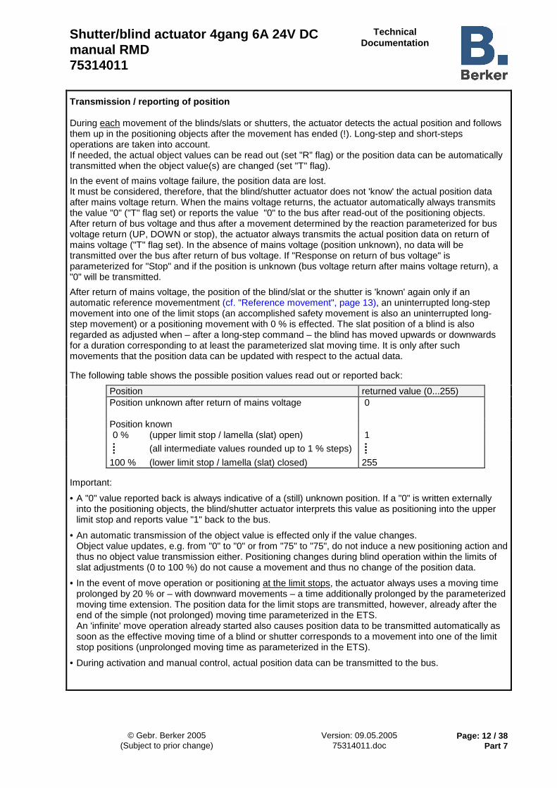
Transmission / reporting of position During each movement of the blinds/slats or shutters, the actuator detects the actual position and follows them up in the positioning objects after the movement has ended (!). Long-step and short-steps operations are taken into account. If needed, the actual object values can be read out (set "R" flag) or the position data can be automatically transmitted when the object value(s) are changed (set "T" flag).
In the event of mains voltage failure, the position data are lost. It must be considered, therefore, that the blind/shutter actuator does not 'know' the actual position data after mains voltage return. When the mains voltage returns, the actuator automatically always transmits the value "0" ("T" flag set) or reports the value "0" to the bus after read-out of the positioning objects. After return of bus voltage and thus after a movement determined by the reaction parameterized for bus voltage return (UP, DOWN or stop), the actuator always transmits the actual position data on return of mains voltage ("T" flag set). In the absence of mains voltage (position unknown), no data will be transmitted over the bus after return of bus voltage. If "Response on return of bus voltage" is parameterized for "Stop" and if the position is unknown (bus voltage return after mains voltage return), a "0" will be transmitted.
After return of mains voltage, the position of the blind/slat or the shutter is 'known' again only if an automatic reference movementment (cf. "Reference movement", page 13), an uninterrupted long-step movement into one of the limit stops (an accomplished safety movement is also an uninterrupted long-step movement) or a positioning movement with 0 % is effected. The slat position of a blind is also regarded as adjusted when – after a long-step command – the blind has moved upwards or downwards for a duration corresponding to at least the parameterized slat moving time. It is only after such movements that the position data can be updated with respect to the actual data. The following table shows the possible position values read out or reported back:
Position returned value (0...255) Position unknown after return of mains voltage 0 Position known 0 % (upper limit stop / lamella (slat) open) 1
(all intermediate values rounded up to 1 % steps)
100 % (lower limit stop / lamella (slat) closed) 255 Important:
• A "0" value reported back is always indicative of a (still) unknown position. If a "0" is written externally into the positioning objects, the blind/shutter actuator interprets this value as positioning into the upper limit stop and reports value "1" back to the bus.
• An automatic transmission of the object value is effected only if the value changes. Object value updates, e.g. from "0" to "0" or from "75" to "75", do not induce a new positioning action and thus no object value transmission either. Positioning changes during blind operation within the limits of slat adjustments (0 to 100 %) do not cause a movement and thus no change of the position data.
• In the event of move operation or positioning at the limit stops, the actuator always uses a moving time prolonged by 20 % or – with downward movements – a time additionally prolonged by the parameterized moving time extension. The position data for the limit stops are transmitted, however, already after the end of the simple (not prolonged) moving time parameterized in the ETS. An 'infinite' move operation already started also causes position data to be transmitted automatically as soon as the effective moving time of a blind or shutter corresponds to a movement into one of the limit stop positions (unprolonged moving time as parameterized in the ETS).
• During activation and manual control, actual position data can be transmitted to the bus.

Shutter/blind actuator 4gang 6A 24V DC manual RMD 75314011
Technical Documentation
© Gebr. Berker 2005 Version: 09.05.2005 Page: 13 / 38 (Subject to prior change) 75314011.doc Part 7
Reference movement In the event of mains voltage failure, the position data are lost. After mains voltage return and also after initial commissioning of the blind/shutter actuator it is therefore necessary to move the blind/lamella (slat) or the shutter into a defined position in order to enable the actuator in the ensueing operation to send unambiguous position reports. A movement into the limit stop positions of the blind or shutter permits a defined position as a reference. Such a movement may be • an uninterrupted long-step move into one of the limit stop positions (an accomplished safety movement
fulfils the same purpose), • a positioning action to 0 %.
A position adjustment can thus be effected by 'simple' control of the device via the bus or by manual control. An 'infinite' move operation adjusts the reference position only if the time used for a movement in this case corresponds to a movement into one of the limit stop positions (downward movement: parameterized moving time + 20 %; upward movement: parameterized moving time + 20 % + parameterized moving time extension).
The lamella (slat) position of a blind is regarded as adjusted, when the blind has moved after a long-step command in upward or downward direction for at least the parameterized lamella (slat) moving time. If, however, a position other than 0 % is to be approached after return of mains voltage (e.g. after reception of a positioning telegram or by the sun protection or master function) and if the blind or the shutter had not yet been moved into any of the limit stop positions, the actuator automatically starts a reference movement into the upper limit stop position. When the reference movement is accomplished, an unambiguous position report can be provided so that the desired position can be approached directly immediately thereafter. If a reference movement after return of mains voltage is interrupted, for instance, by a step operation, the position is still unknown as before. A terminated reference movement of the blind also adjusts the lamella (slat) position.
upper limit position
blind shutter
0 %
100 %
0 %
100 %
referencemovement
A reference movement is the time needed for a movement into the upper limit stop position prolonged by 20 % and additionally by the parameterized moving time extension. The moving time can be adjusted separately for each output channel. A reference movement cannot be retriggered.
For a positioning move of the lamellas (slats) by the objects after mains voltage return, a reference movement of the lamellas (slats) becomes necessary, if the blind has not yet been moved upwards or downwards for at least the parameterized lamella (slat) moving time. In this case, the actuator always moves the lamellas (slats) for the duration of the parameterized lamella (slat) moving time into the completely open position (0 %) and then to the desired position. Important:
• With the sun protection function, a reference movement can additionally be forced before each sun protection movement even if the positions are 'known'. With parameter setting "Reference move before sun protection positioning " = "yes" it can be ensured in the sun protection mode that the blind/shutter always moves exactly to the parameterized sun protection position even after repeated positioning movements.
• In the event of a position correction after a sun protection, master or safety function, the position to be reached will be approached automatically by a reference movement only if the actual position data have been 'lost' during the function as a result of a mains voltage failure.

Shutter/blind actuator 4gang 6A 24V DC manual RMD 75314011
Technical Documentation
© Gebr. Berker 2005 Version: 09.05.2005 Page: 14 / 38 (Subject to prior change) 75314011.doc Part 7
Positioning movements The moving time parameterized separately for each output channel serves as a reference for all positioning movements. In order to achieve high-precision positioning of the blinds/lamellas (slats) or shutters, the moving times should be determined as exactly as possible (cf. "Moving times / step operation / move operation / switch-over delay / moving time extension ", page 8).
For a positioning task, the blind/shutter actuator always computes the moving time as a linear function of the position value. For all travelling movements in upward direction, the parameterized moving time extension is automatically added to the moving time computed. For positioning movements into the lower or upper limit stop positions (0 % or 100 %) the moving time is additionally always 20 % longer than the parameterized moving time. A distinction must be made between positioning movements which are effected either directly by the positioning objects or by activation of the sun protection or central functions. • Positioning by positioning objects:
Each blind/lamella (slat) or shutter can be positioned directly. The last position received is always executed. It is possible to receive new positioning telegrams while a positioning movement is still in progress. In this case, the actuator reverses the moving direction immediately when the new position to be approached lies in the opposite direction. If a lamella (slat) position is received during positioning of the blind, the blind positioning movement is first accomplished before the lamella (slat) is positioned. If a blind position is received during positioning of the lamella (slat), the actuator interrupts lamella (slat) positioning and moves to the new blind position (with a reference movement after a mains voltage failure). The lamella (slat) position last received is adjusted by the actuator only thereafter.
During positioning of a blind, the lamella (slat) position is generally followed up. After mains voltage return, the lamella (slat) position may be unknown, if no long-step command for upward or downward movement has occurred for at least the parameterized lamella (slat) moving time or if no lamella (slat) positioning has been effected yet. If the lamella (slat) position is unknown after mains voltage return, the lamella (slat) is moved into the closed position (100 %) during positioning of the blind.
A positioning movement induced by the objects can at any time be interrupted by a short-step or a long-step command (same priority for long-step or short step commands and for positioning via the objects).
• Positioning by the sun protection or master functions:
In the sun protection or master function, the blind/lamella (slat) or shutter positions to be approached are directly parameterized depending on the type of blind/shutter. In case of a blind, sun protection or central positioning of the blind comes first before the parameterized lamella (slat) position is approached (cf. "Sun protection function" resp. "Central funtion").
Important:
• If the blinds/slats or shutters are often (several times a day) positioned directly, positioning may becomme less precise in the course of time. Such deviations from the set position are mostly due to external physical influences. In order to achieve always precise positioning movements, it is recommended to move the blind or shutter at least once every day into one of the limit stop positions (movement like reference movement) for position adjustment. This can be achieved, for instance, by a 'manual' long-step movement or by an automatical or time-controlled long-step or positioning movement.
• In the event of bus voltage failure, positioning movements in progress are interrupted and the parameterized response is executed. On activation of the manual control, positioning movements are interrupted, too.

Shutter/blind actuator 4gang 6A 24V DC manual RMD 75314011
Technical Documentation
© Gebr. Berker 2005 Version: 09.05.2005 Page: 15 / 38 (Subject to prior change) 75314011.doc Part 7
Positioning particulars when blind/shutter type = "Blind":
In the most usual types of motor-driven blinds, the lamellas (slats) are adjusted by a variation of the height of the blind. A variation of blind position therefore theoretically also influences the position of the lamellas (slats). Since lamella (slat) positioning should always be independent and unambiguous, the actuator does not perform changes of blind position, when the computed time needed for a position change falls into the parameterized lamella (slat) moving time. In the same way, the blind position changes, when the lamella (slat) position changes. The actuator takes the relationship between blind and slat moving time into account. When slats are positioned, the actuator always computes the resulting blind position and transmits this value as 'new' blind position to the bus.
The following diagram shows the change of the blind position for a change of the slat angle:
slat = 50 %
slat = 100 %
slat = 0 %beam of light
parametrizedslat movement time
e.g. blind = 46 %
e.g. blind = 48 %
e.g. blind = 50 %(set position of blind)
This example shows that lamella (slat) angle changes result in a new blind position which is also followed up in the positioning objects. If the actuator receives in this case a 'new' blind position of e.g. 47 %, the actuator does not induce a movement, as the computed moving time falls into the parameterized lamella (slat) moving time and thus coincides with the slat movement. A change of the blind position to 55 % in this example induces a blind movement as the change lies beyond the slat movement (0 to 100 %).
For each positioning procedure, the set position of the blind is referred to a lamella (slat) position of 100 %. For this reason, the blind position reported back during lamella (slat) repositioning (0 to 100 %) is always below the set position. Exception: A set position of the blind of 0 % (upper limit stop) is referred to a lamella (slat) position of 0 %. In this case, too, a repositioning movement of the lamella (slat) causes a change of the blind height (short downward movement). Only in this case is the blind position reported back greater than the set position . Important:
• With the sun protection and master functions, it is possible to predefine the positions of the blind and the lamellas (slats). It should be noted here that the actuator on activation of the function first approaches the blind position before positioning the lamellas (slats). By positioning of the lamellas (slats) it is possible that the blind position reported back to the bus differs from the set position.
• The smaller the ratio of lamella (slat) moving time to blind moving time the more precise the positioning action and the less the influence exerted by slat angle positioning on the height of the blind.

Shutter/blind actuator 4gang 6A 24V DC manual RMD 75314011
Technical Documentation
© Gebr. Berker 2005 Version: 09.05.2005 Page: 16 / 38 (Subject to prior change) 75314011.doc Part 7
Safety function The blind/shutter actuator has two safety functions with separate assignment to the blind or shutter channels. The safety functions can be activated or deactivated by separate objects. The priority of the objects can be parameterized. Safety reaction
The reaction of the assigned output channels at the beginning and at the end of a safety function can be preset. Moreover, when the positioning function is enabled (parameter "Positioning" on card "General" on "Enabled"), the blind/slat or shutter position set before or received during safety can be followed up after the end of a safety lock.
Response at the beginning of a safety function The actuator moves the blinds or shutters alternatively into one of the limit stop position, if the response at safety is parameterized for "Moving up" or "Moving down". With these settings, the blinds or shutters are locked up in the limit position after the end of the safety movement. If the response at safety at the beginning of the safety function is parameterized for "No reaction", no movement is started and the output channels are locked in the actual position. With respect to all other bus-controllable functions of the actuator, the safety function has the highest priority. This means that all functions in progress for the outputs concerned as, for instance, positioning by the objects or sun protection function active, will be aborted and the safety reaction is executed. The safety function can be interrupted only by manual control on the device itself. As far as the response at the end of a safety function is concerned, the following cases must be distinguished in consideration of the parameter settings: I. No tracking of the blind/lamella (slat) or shutter position after safety deactivation
(Parameter "Tracking of position on safety deactivation" = "No follow-up")
At the end of a safety function, the actuator immediately re-enables the output channels concerned when the setting is "moving up" or "moving down" and approaches the corresponding limit stop positions. If the response at the end of a safety function is parameterized for "No reaction", the corresponding outputs are enabled without starting a new movement. If enabling by "No reaction" occurs during a safety movement still in progress, the outputs are enabled without interrupting the movement. A positioning movement interrupted by a safety function (new position not yet reached) or a sun protection or master function is not accomplished after safety deactivation.
II. Tracking of the blind/lamella (slat) or shutter position after safety deactivation
(Parameter "Tracking of position on safety deactivation" = "safety 1 / safety 2 / safety 1 and 2")
At the end of a safety function, the actuator corrects the blind/lamella (slat) position in the blind mode and the shutter position in the shutter mode. The position preset before or received during safety lock via the positioning objects is followed up. Exception: If the position was unknown before the safety function due to an existing mains voltage failure, no position will be tracked after the end of the safety function! There will not be any position tracking either, even if position telegrams have been received during the safety lock. If no position can be tracked, the actuator's response at the end of safety will be to start a movement into the limit stop positions depending on the setting of the "Response at the end of safety function" parameter. If the setting is "moving up" or "moving down", the actuator immediately re-enables the output channels concerned and approaches the corresponding limit stop positions. If the response at the end of a safety function is parameterized for "No reaction", the corresponding outputs will be enabled without starting a new movement. If enabling is by "No reaction" while a safety movement is still in progress, the outputs will be enabled without interrupting the movement. A positioning movement interrupted by the safety function (no new position reached as yet) or a sun protection or master function will not be accomplished after safety deactivation.

Shutter/blind actuator 4gang 6A 24V DC manual RMD 75314011
Technical Documentation
© Gebr. Berker 2005 Version: 09.05.2005 Page: 17 / 38 (Subject to prior change) 75314011.doc Part 7
Depending on the "Tracking of blind position / shutter position on safety deactivation" parameter, it is possible to specify independently for both safety functions whether a position tracking is to be performed on safety deactivation: Setting Response at the end of the safety function(s) No tracking as set in the "Response... at the end" parameter Safety 1 position tracking only for safety function 1, if position is
known.*
Safety 2 position tracking only for safety function 2, if position is known.*
Safety 1 and 2 position tracking for for both safety functions, if position is known.
*: If an output channel is assigned to both safety functions, there will be a position follow-up only if the
safety function to be followed up was the last to be deactivated. Safety assignment
Each output channel can be assigned separately to safety functions 1 or 2 or alternatively to both safety functions. If a channel is intended to respond to both functions, the safety objects resp. the functions are combined by a logic OR. This means that the corresponding output channel goes into the safety lock state as soon as one of the objects is active. In this case, the channel will be re-enabled only if both objects are deactivated. Only then can a position follow-up be performed at the end of the safety lock of a channel assigned to both functions! If the setting is "No assignment", the safety function for this output channel is deactivated. Manual control and safety function
Compared to all other bus-controllable function of the actuator, the safety functions have the highest priority. The safety functions can be interrupted only by manual control on the device itself. After a manual control, the actuator automatically reactivates the safety function(s) for the outputs assigned, if the safety objects had been activated before or during a manual control. The parameterized "Response at the beginning of the safety function" is then re-executed.
If a safety function was deactivated during manual control, (object update "Not active"), the parameterized "Response at the beginning of the safety function" is re-executed after the end of manual control. It is assumed that the safety function was activated before or during manual control. Information about deactivation of a safety function during manual control with position tracking (Parameter "Tracking of position on safety deactivation" = "safety 1 / safety 2 / safety 1 and 2"):
If a safety function was deactivated during manual control and if the position is to be tracked at the end of the safety function, the position that was active before manual control or the position that was changed during manual control will be tracked for the outputs concerned (response at the end of manual control like "No reaction"). If the position was unknown before manual control due to a then existing mains voltage failure, no position will be tracked at the end of manual control and after safety function deactivation. There is no tracking either even if position telegrams have been received or if the blind/shutter has been adjusted during manual control. If no position can be tracked, the actuator starts a movement into the limit stop positions as a reaction at the end of manual control and with deactivated safety function. The movement depends on the setting of the "Response at the end of the safety function" parameter.

Shutter/blind actuator 4gang 6A 24V DC manual RMD 75314011
Technical Documentation
© Gebr. Berker 2005 Version: 09.05.2005 Page: 18 / 38 (Subject to prior change) 75314011.doc Part 7
Cyclical monitoring
Both safety objects can be cyclically monitored for the reception of telegrams. When monitoring is enabled, the actuator expects a telegram update to both safety objects. If no telegrams are received during the monitoring time, the safety function corresponding to the missing telegram will be activated. The safety function can be deactivated again when a safety unlock command is received. The cycle time of the transmitters should be shorter than the monitoring time parameterized in the blind/shutter actuator in order to ensure that at least one telegram can be received during the monitoring time. Safety function information:
• The time needed by an output for a safety movement into the limit stop positions is determined by the "Move operation " parameter on the "Output X" cards. For this reason, the safety movement can be as long as the parameterized extended moving time (downward movement: parameterized moving time + 20 %; upward movement: parameterized moving time + 20 % + parameterized moving time extension) or also 'infinitely' long. Safety movements cannot be retriggered.
• After a movement into the limit stop positions at the beginning or at the end of a safety function
(response "Moving up" or "Moving down") the lamellas (slats) are no separately positioned in the blind mode. The lamellas (slats) are completely open (0 %) after an "Upward movement" or completely closed (100 %) after a "Downward movement". The lamellas (slats) can be readjusted only in the event of a tracking action at the end of safety.
• After return of bus voltage, the safety functions are always deactivated. In the event of a safety lock with object value "0", an object update ("0" telegram) must first be made after bus voltage return before the safety function is activated.
• An object update of the safety objects ("ON" after "ON" resp. "OFF" after "OFF") yields no reaction.
• The safety functions interrupt the sun protection or the master function and all other travel movements. A safety-locked output cannot be influenced by a sun protection or by a master function. The sun protection and master functions are active again only after the safety lock has been deactivated and after a new telegram update of the sun protection or master objects for the enabled output. Long-step or short-step commands during an active safety function will be rejected.

Shutter/blind actuator 4gang 6A 24V DC manual RMD 75314011
Technical Documentation
© Gebr. Berker 2005 Version: 09.05.2005 Page: 19 / 38 (Subject to prior change) 75314011.doc Part 7
Sun protection functions The blind/shutter actuator has two sun protection functions with optional assignment to the blind or shutter channels. The sun protection functions can be activated or deactivated via separate objects. The polarity of the objects can be parameterized. The sun protection functions are available only if the positioning function is enabled (parameter "positioning" on card "general" set to "enabled") and are separately enabled by parameter "sun protection function" on card "general". Sun protection reaction / sun protection positioning
The response of the output channels assigned at the beginning and at the end of a sun protection function can be predefined. The blind/lamella (slat) or shutter position that was set before or received during the function can be tracked after the end of sun protection.
Response at the beginning of a sun protection function: The actuator moves the blinds/lamellas (slats) or the shutters to the positions parameterized in the ETS for each output. In the blind mode, the blind is positioned first during sun protection postioning before the parameterized lamella (slat) position is approached thereafter. Due to subsequent positioning of the slats, it is possible that the blind position reported back to the bus is different from the set position. The positions can be predefined in steps of 1 % between 0 % and 100 %. Moreover, it is possible with the sun protection function, to force a reference movement before each sun protection movement, and this even if the positions are known. With the parameter setting "Reference movement befor sun protection positioning" = "yes" it can be ensured that in case of sun protection the exact parameterized position is always approached even after several positioning movements. If the parameter is set to "No", the actuator performs a reference movement for reference position adjustment before a sun protection positioning only after a return of mains voltage (position unknown).
As far as the response at the end of a sun protection function is concerned, the following cases must be distinguished in consideration of the parameter settings: I. No tracking of the blind/lamella (slat) or shutter position after sun protection end
(Parameter "Response of the blind / shutter at the end of automatic sun protection" = "No change" / "Moving up" / "Moving down" / "Stop")
With the "Moving up" or "Moving down" setting, the actuator moves the blind/shutter at the end of a sun protection function into the respective limit stop positions. If the response at the end of a sun protection function is parameterized for "No reaction" or "Stop", no new movement is started. If the sun protection is deactivated by "No reaction" while a sun protection positioning movement is still in progress, the movement is accomplished. If the sun protection is deactivated by "Stop" while a sun protection positioning movement is still in progress, the movement is interrupted and the actual position reported back to the bus.
II. Tracking of the blind/lamella (slat) or shutter position after sun protection end
(Parameter "Response of the blind / shutter at the end of automatic sun protection" = "Follow up position before sun protection")
At the end of the sun protection function, the actuator corrects the blind/lamella (slat) or shutter position in the blind mode. The position preset before the sun protection function or received during automatic sun protection positioning via the positioning objects is tracked (sun protection priorities with respect to 'move / step / positioning' must be observed).
Exception: If the position was unknown before the sun protection function due to an existing mains voltage failure, no position will be tracked after the end of the sun protection function. There will not be any position tracking either, even if position telegrams have been received during automatic sun protection. If no position can be tracked, the actuator's response at the end of the sun protection function will be to start a movement into the upper limit position ("Moving up").

Shutter/blind actuator 4gang 6A 24V DC manual RMD 75314011
Technical Documentation
© Gebr. Berker 2005 Version: 09.05.2005 Page: 20 / 38 (Subject to prior change) 75314011.doc Part 7
Priority Of all bus-controllable functions, the safety functions have the highest priority. The safety functions can be interrupted only by manual control. The next lower priority is reserved for the up to four central functions (only in 2x2-channel operation). If the sun protection function is generally enabled, the priority evaluation can be defined by the "Priority 'Move / Step / Positioning' for 'Sun protection" parameter on card "General". The evaluation of telegrams can be preset with respect to the sun protection objects and the short-step resp. long-step objects.
'Move / Step / Positioning'sun protection
sun protection
safety
central 1, 2, 3, 4
safety
central 1, 2, 3, 4
'Move / Step / Positioning'
same priority sun protection above'Move / Step / Positioning'
sun protection
safety
central 1, 2, 3, 4
'Move / Step / Positioning'
'Move / Step / Positioning' above sun protection
Three cases can be distinguished:
1. 'Move / Step / Position' has the same priority with respect to 'Sun protection' (default): With this parameterization, a sun protection function can be aborted by a short-step or a move operation. Automatic sun protection is also aborted by postioning via the positioning objects. In this case, the parameterized "Response at the end of automatic sun protection" is not executed. The sun protection is not automatically re-excuted. The sun protection function is restarted only after an object update "Active" is performed depending on polarity.
2. 'Move / Step / Positioning' has higher priority than 'Sun protection': With this setting, the automatic sun protection is aborted by step or move operation or by positioning via the objects. The parameterized "Response at the end of automatic sun protection" is not executed and it is not possible either to restart the sun protection function. The sun protection function can be activated only after the blind or shutter has been moved into the upper limit position by an uninterrupted move operation via the objects ('manual' enable movement). As long as the enable movement has not yet been effected, all attempts to activate the sun protection function will be rejected. A manual control operation, an upward movement after bus voltage return or an upward movement after safety deactivation are no enable movements.
3. 'Sun protection has higher priority than 'Move / Step / Positioning': With this setting, an activated sun protection function cannot be aborted by step or move operation or by positioning via the objects. 'Move / Step / Positioning' commands will again be accepted only after the automatic sun protection is completely deactivated.

Shutter/blind actuator 4gang 6A 24V DC manual RMD 75314011
Technical Documentation
© Gebr. Berker 2005 Version: 09.05.2005 Page: 21 / 38 (Subject to prior change) 75314011.doc Part 7
Sun protection assignment
Each output channel can be assigned separately to the individual sun protection functions or alternatively to both sun protection functions. If a channel is to react to both functions, the sun protection objects or the functions are combined by a logic "AND" and a logic "OR" depending on the "assigned" parameter. In the event of a logic AND operation, the sun protection response of the output assigned will be executed only after both sun protection functions have been activated via the objects. In this type of logic parametrization, the sun protection is terminated when one of the functions is deactivated. After deactivation, the position can be followed up, if necessary. In the event of a logic OR operation, the sun protection response of the output assigned will be executed, when one of the sun protection functions has been activated via the objects. In this case, the sun protection is terminated only when both functions are deactivated. Position follow-up is possible only thereafter. When the setting is "Not assigned", the sun protection function is deactivated for this channel. Sun protection function information:
• After return of bus voltage, the sun protection functions are always deactivated. In the event of sun protection activation with object value "0", an object update ("0" telegram) must first be made after bus voltage return before the sun protection function is activated. Also in the event of a logic combination between sun protection functions (AND / OR), an update telegram must be sent to both objects after bus voltage return before a sun protection function depending on the logic operation can be executed at all.
• An object update of the sun protection objects from "Deactivated" to "Deactivated" yields no reaction. An update from "Activated" to "Activated" restarts the sun protection function only if this function has been interrupted depending on the parameterized evaluation of priorities.
• The safety functions interrupt also the sun protection function(s). A safety-locked output cannot be influenced by a sun protection function. A sun protection function can only be reactivated after deactivation of the safety lock by a new telegram update of the sun protection objects.
• An activation of the manual control mode interrupts the sun protection function(s). A sun protection function can only be reactivated after deactivation of the manual control mode by a new telegram update ("Sun protection function activated") of the sun protection objects.

Shutter/blind actuator 4gang 6A 24V DC manual RMD 75314011
Technical Documentation
© Gebr. Berker 2005 Version: 09.05.2005 Page: 22 / 38 (Subject to prior change) 75314011.doc Part 7
Master functions The blind/shutter actuator has up to four master functions with optionally separate assignment to the blind or shutter channels only in 2x2-channel operation. The master functions can be activated or deactivated via separate objects. The polarity of the objects can be parameterized. The master functions are available only if the positioning function is enabled (parameter "Positioning" on card "General" set to "Enabled") and are separately enabled by parameter "Master function" on card "General". Response with master functions / master positioning
The response of the output channels assigned at the beginning and at the end of a master function can be predefined. The blind/lamella (slat) or shutter position that was set before or received during the function can be followed up after the end of a master function.
Response at the beginning of a master function: The actuator moves the blinds/lamellas (slats) or the shutters to the master positions parameterized in the ETS for each output. In the blind mode, the blind is positioned first during master postioning before the parameterized lamella (slat) position is approached thereafter. Due to subsequent positioning of the slats, it is possible that the blind position reported back to the bus is different from the set position. The positions can be predefined in steps of 1 % between 0 % and 100 %. If (master) positioning is performed for the first time after mains voltage return (position unknown), a reference movement for the purpose of reference position adjustment is started first.
The response at the end of a master function is preset for all master functions in common. The following cases must be distinguished in consideration of the parameter settings: I. No tracking of the blind/lamella (slat) or shutter position after end of master function
(Parameter "Response of the blind / shutter at the end of the master function" = "No change" / "Moving up" / "Moving down" / "Stop")
With the "Moving up" or "Moving down" setting, the actuator moves the blind/shutter at the end of a master function into the respective limit stop positions. If the response at the end of a master function is parameterized for "No reaction" or "Stop", no new movement is started. If the master function is deactivated by "No reaction" while a master positioning movement is still in progress, the movement is accomplished. If the master function is deactivated by "Stop" while a sun protection positioning movement is still in progress, the movement is interrupted and the actual position reported back to the bus.
II. Tracking of the blind/lamella (slat) or shutter position after end of master function
(Parameter "Response of the blind / shutter at the end of master function" = "Follow up position before master function")
At the end of a master function, the actuator follows up the blind and lamella (slat) position in the blind mode and the shutter position in the shutter mode. The position preset before the master function resp. the position received during the master function via positioning objects will be tracked.
Exception: If the position was unknown before the master function due to an existing mains voltage failure, no position will be tracked after the end of the master function. There will not be any position tracking either, even if position telegrams have been received during the master function. If no position can be tracked, the actuator's response at the end of the master function will be to start a movement into the upper limit position ("Moving up")

Shutter/blind actuator 4gang 6A 24V DC manual RMD 75314011
Technical Documentation
© Gebr. Berker 2005 Version: 09.05.2005 Page: 23 / 38 (Subject to prior change) 75314011.doc Part 7
Priority Of all bus-controllable functions, the safety functions have the second highest priority. The master function can be interrupted only by manual control and by the safety functions. The next lower priority is reserved for the sun protection functions resp. operation via the objects 'Move', 'Step' and 'Positioning', which cannot interrupt the central functions. Master assignment
Each of the two output channels in 2x2-channel operation can be assigned separately to individual or alternatively to several or to all four master functions. The assignment of a channel to the master functions is preset by the "Assignment" paramenter. If a channel is assigned to several master functions, the channel reacts only to the function last activated. To deactivate the master function again, the function last activated must be deactivated.
Example: Shutter output 1/3 is assigned to master functions 1, 2 and 3. Each master function has different position values: Master 1 30 %, Master 2 50 % and Master 3 75 %. When master function 1 is activated, the output moves to the 30 % position. When master function 2 is activated, the 50 % position is approached. Thereafter, master function 3 is activated and shutter position 75 % is approached. To stop the master function, master function 3 must be deactivated. The parameterized "Response at the end of the master function" is executed thereafter. The deactivation of functions Master 1 or Master 2 shows no reaction in this case. If the setting is "None", the master function for this output channel is deactivated. Master function information:
• After return of bus voltage, the master functions are always deactivated. In the event of master function activation with object value "0", an object update ("0" telegram) must first be made after bus voltage return before the master function is activated.
• An object update of the master objects from "Deactivated" to "Deactivated" yields no reaction. An update from "Activated" to "Activated" restarts the master function only if this function has been interrupted depending on the parameterized evaluation of priorities. e.g. by a safety function.
• The safety functions interrupt also the sun protection function(s). A safety-locked output cannot be influenced by a master function.
• An activation of the manual control mode interrupts all master function(s). A master function can only be reactivated after deactivation of the manual control mode by a new telegram update ("Master functions activated") of the master object.

Shutter/blind actuator 4gang 6A 24V DC manual RMD 75314011
Technical Documentation
© Gebr. Berker 2005 Version: 09.05.2005 Page: 24 / 38 (Subject to prior change) 75314011.doc Part 7
Bus and mains voltage / programming procedure Response in case of bus voltage failure:
The response in case of bus voltage failure is predefined by the "Response to bus voltage failure" parameter on the "General" card. The following actions can be parameterized: blind or shutter moving into upper limit stop position ("Moving up"), blind or shutter moving to lower limit stop position ("Moving down"), movements in progress being stopped ("Stop") or no reaction taking place ("No reaction" / movements still in progress will be accomplished). Manual control is possible depending on the "Manual control during bus voltage failure" on the "Manual control" card. Response to mains voltage failure:
The actuator needs a mains voltage supply for operation. In the event of mains voltage failure, the position data are lost and all outputs switch off (stop). Manual control is then no longer possible. Safety functions activated via the bus remain active and sun protection or master functions are rejected. Response to bus and mains voltage failure:
As in a normal mains failure, all position data are lost and all outputs switch off (stop). Manual control is then no longer possible. Safety functions activated via the bus and also sun protection or master functions are rejected. Response on return of bus voltage:
The response depends on whether mains voltage is present or not when the bus voltage returns. If the mains is present on return of bus voltage, the reaction is fixed by the "Response on return of bus voltage" parameter on the "General" card. The following actions can be parameterized: blind or shutter moving to upper limit position ("Moving up"), blind or shutter moving to lower limit position ("Moving down"), movements in progress being stopped ("Stop"). Manual control – if activated – will be terminated. In an unprogrammed actuator, the reaction after bus voltage return is factory-adjusted to "Stop".
If there is no mains voltage on return of bus voltage, all output channels remain off (Stop). Bus communication is, however, possible, i.e. the safety functions can be activated. Activation of the sun protection or master functions, step- or move operation commands and positioning via the objects are rejected. A safety function – if activated – will be executed when the mains voltage returns later on. If no safety function has been activated during the mains failure (bus voltage available), the actuator executes the parameterized "Response on bus voltage return" when the mains is restored later on. Manual control is not possible.
After bus voltage return and a movement as parameterized for the response on bus voltage return (moving up, moving down or stop) the actual position data will always be transmitted when mains voltage is available ("T" flag set). If mains voltage is not available (position unknown), no position data will be transmitted to the bus after bus voltage return. If the "Response on bus voltage return" is parameterized for "Stop" and if the position is unknown (bus voltage return after mains voltage return), a "0" is transmitted.

Shutter/blind actuator 4gang 6A 24V DC manual RMD 75314011
Technical Documentation
© Gebr. Berker 2005 Version: 09.05.2005 Page: 25 / 38 (Subject to prior change) 75314011.doc Part 7
Response to mains voltage return:
The response depends on whether bus voltage is available or not when the mains voltage returns. If bus voltage is available, all outputs are being shut off or remain off (stop) until a new bus telegram is received and the switching state changes.
Exception: The actuator automatically reactivates the safety function(s) in the outputs assigned, if the safety objects were activated before or during the mains failure. The parameterized "Response at the beginning of the safety function" is re-executed. A safety function activated before the mains failure and deactivated during the failure does not start a new movement on return of mains voltage. If, during mains failure, a safety function was activated and then deactivated again, the actuator starts a new movement for the outputs assigned after mains voltage return as parameterized for "End of the safety function". The outputs concerned are in any case re-enabled after safety deactivation.
If the bus voltage is not present on return of mains voltage, the parameterized "Response on bus voltage failure" is started ("Stop" is factory-adjusted in unprogrammed actuators).
The sun protection or master functions are always deactivated after mains voltage return. Manual control is possible again. After mains voltage return, the position of the blind/lamella (slat) or shutter is not 'known' until a reference movement (cf. "Reference movement", page 13), an uninterrupted move operation into one of the limit stop positions (an accomplished safety movement is also a move operation or positioning to 0 % has occurred. The lamella (slat) position of a blind is considered as adjusted when the blind has moved for at least the parameterized lamella (slat) moving time after a long-step movement in upward or downward direction. Only after such movements will the position data be updated depending on the actual position. Response to bus and mains voltage return:
The parameterized "Response on bus voltage return" is started. Manual control in this case is possible. (Cf. also "Response on bus voltage return" / "Response on mains voltage return") Programming procedure:
After the end of programming by the ETS or after a bus reset (bus voltage return), the parameterized "Response on bus voltage return" is executed. After programming, the manual control mode is terminated. Manual control depending on bus and mains voltage:
Manual control is only possible when mains voltage is available. Depending on the "Manual control on bus voltage failure" parameter on the "Manual control" card, manual control with no bus voltage applied is possible. An activated manual control mode ends on return of bus voltage.

Shutter/blind actuator 4gang 6A 24V DC manual RMD 75314011
Technical Documentation
© Gebr. Berker 2005 Version: 09.05.2005 Page: 26 / 38 (Subject to prior change) 75314011.doc Part 7
Manual control The actuator as delivered has the manual control mode already enabled. The four keys on the device front panel permit comfortable local operation of the up to 4 output channels also without bus voltage being present. The different operating states are indicated by up to 11 red LEDs. For manual control, the mains supply must be on.
A1 A2 A3 A4
OFF
Activation of manual control and operation:
The manual control mode can be activated temporarily or permanently. Permanent manual control:
Activation: 1. Press the " " key for at least 5 seconds. 2. The red LED beside the " " key lights up statically. The actuator is now permanently
in the manual control mode, control via the EIB is disabled and all output channels are stopped.
Operation: A short press (< 1 second) on the " " key selects the output channel which is to be operated by manual control. The two status LEDs (��) of the output selected in the LED array start flashing. Pressing the select key repeatedly permits switching between the outputs (A1 → A2 → A3 → A4 → A1 → ...). If the actuator works in 2x2-channel operation, the outputs are automatically combined and controlled in common. (A1 / A3→ A2 / A4 → A1 / A3 → A2 / A4 → A1 / A3 → ...). The "�" and "�" keys can be used to control the selected output channel and to modify the switching status and the sense of movement. The LEDs beside the keys indicate the switching state of the selected channel. The switching states of non selected outputs are indicated as for 'normal' bus operation by means of the LEDs of outputs A1 thru A4 in the LED array.
Deactivation: - by pressing the " " key for at least 5 secs. until the corresponding LED goes out or - by bus reset or reapplication of bus voltage (return of bus voltage), or - by switching off the mains voltage.
Master stop function:
When the actuator is in the permanent manual control mode, all output channels can be shut off at the same time (stop). A press on the "OFF" key executes the stop function. All relays are switched off immediately.
The master stop function is available in the permanent manual control mode only!

Shutter/blind actuator 4gang 6A 24V DC manual RMD 75314011
Technical Documentation
© Gebr. Berker 2005 Version: 09.05.2005 Page: 27 / 38 (Subject to prior change) 75314011.doc Part 7
Temporary manual control mode:
Activation: 1. The " " select key must be pressed briefly (< 1 sec.). 2. The red LED(s) of output channel 1 (4-channel operation) resp. 1/3 (2x2-channel
operation) in the LED array start flashing. The actuator is now temporarily in the manual control mode, control from the EIB is disabled and all output channels are stopped. The red LED beside the select key is off!
Operation: A short press (< 1 sec.) of the " " key selects the output channel which is to be controlled manually. The two status LEDs (��) of the output selected in the LED array start flashing. Pressing the select key repeatedly permits switching between the outputs and terminating the temporary manual control mode (A1 → A2 → A3 → A4 → End). If the actuator works in the 2x2-channel mode, the outputs are combined automatically and controlled in common. (A1 / A3→ A2 / A4 → End). After termination of the manual control mode, the actuator goes back to 'normal' bus operation. The "�" and "�" keys can be used to control the selected output channel and to modify the switching status and the sense of movement. The LEDs beside the keys indicate the switching state of the selected channel. The switching states of non selected outputs are indicated as for 'normal' bus operation by means of the LEDs of outputs A1 thru A4 in the LED array.
Deactivation: - if no further key is pressed after more than 5 seconds, or - - when the select key is pressed once again after all outputs channels have been selected
once with the key, or - - by bus reset or reapplication of bus voltage (bus voltage return) or - - by switching off the mains voltage.
If the " " key is pressed in the temporary manual control mode for at leat 5 seconds, the actuator changes over to permanent manual control. Pressing the "OFF" key in the temporary manual control mode yields no reaction!
On activation of the temporary or permanent manual control mode, all output channels are generally stopped and active safety functions resp. sun protection and master functions are aborted. Output channel control via the bus is disabled. Safety functions are reactivated after deactivation of the manual control mode, if they have not been cancelled (cf. "Safety function", page 16). Sun protection functions are generally rejected or discontinued after deactivation of the manual control mode. The actual position of the blind and lamella (slat) or the shutter is followed up in the positioning objects during activation of manual control and, if necessary, transmitted to the bus. Manual control mode enable:
The manual control mode is available only when mains voltage is present. The manual control mode generally can be disabled by selecting the parameter "Manual control = disabled" on the "Manual control" card. Depending on the "Manual control on bus voltage failure" parameter, it is possible to specify in addition (with manual control generally disabled) whether a manual control is to be permitted even in the event of bus voltage failure. An activated manual control mode is terminated on return of bus voltage. Manual control mode information:
• The parameterized "Break during change of movement direction" is taken into account also for the manual control mode.
• On activation and during manual control, the actual positions can be transmitted to the bus.
• In the manual control mode, only move operation (long depression of key) and a stop command (short depression of key) are possible. When delivered ex factory (actuator not yet programmed), the move operation is factory-adjusted to 'infinite'. After programming of the device with the ETS, the moving time parameterized for each output channel under "Move operation" is applicable.
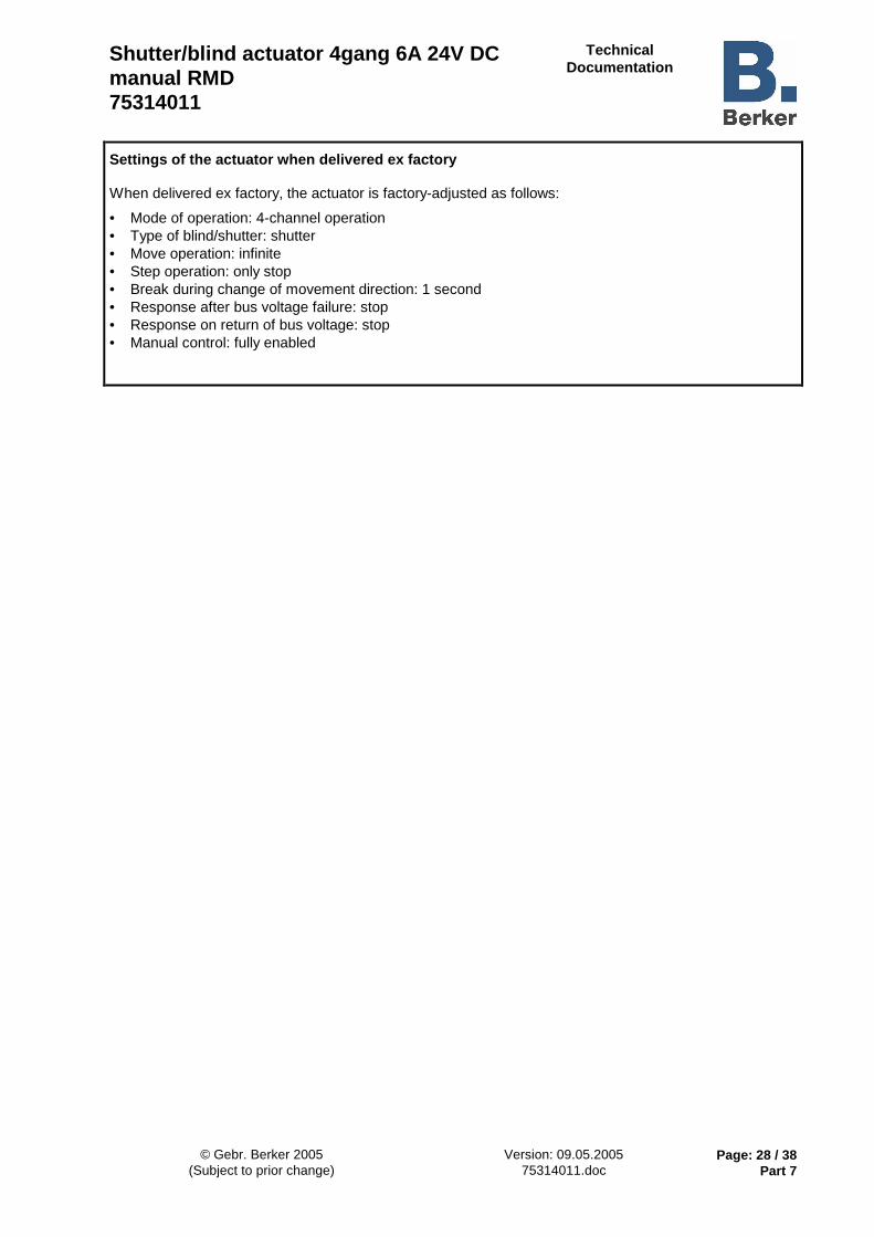
Shutter/blind actuator 4gang 6A 24V DC manual RMD 75314011
Technical Documentation
© Gebr. Berker 2005 Version: 09.05.2005 Page: 28 / 38 (Subject to prior change) 75314011.doc Part 7
Settings of the actuator when delivered ex factory When delivered ex factory, the actuator is factory-adjusted as follows:
• Mode of operation: 4-channel operation • Type of blind/shutter: shutter • Move operation: infinite • Step operation: only stop • Break during change of movement direction: 1 second • Response after bus voltage failure: stop • Response on return of bus voltage: stop • Manual control: fully enabled

Shutter/blind actuator 4gang 6A 24V DC manual RMD 75314011
Technical Documentation
© Gebr. Berker 2005 Version: 09.05.2005 Page: 29 / 38 (Subject to prior change) 75314011.doc Part 7
Parameters Description: Values: Comment:
General
Mode of operation
4-channel operation
2 x 2-channel operation
4 output channels working independently of each other or 2 x 2 channels working in combination. All four channels working independently of each other. 2 channels consisting of 2 connected channels each.
Positioning (HA)
enabled disabled
This parameter specifies whether the positioning function, which is required a.o. for the sun protection and master function, is enabled. The position function is enabled. The sun protection or master functions and the positioning objects are available. The positioning function is disabled. Only "safety" resp. short-step or move operation are possible.
Blind/shutter type Blind Shutter
The actuator controls only blinds. The actuator controls only shutters.
Sun protection function (HA)
enabled disabled
The sun protection function is enabled. The sun protection function is disabled.
Only when "Positioning" = "enabled"!
Priority 'Move / Step / Positioning' with respect to 'Sun protection' (HA)
Same priority 'Move / Step / Positioning' above 'Sun protection' 'Sun protection' above 'Move / Step / Positioning'
Defines the priority of incoming telegrams.
'Move / Step / Positioning'sun protection
sun protection
safety
central 1, 2, 3, 4
safety
central 1, 2, 3, 4
'Move / Step / Positioning'
same priority sun protection over'Move / Step / Positioning'
sun protection
safety
central 1, 2, 3, 4
'Move / Step / Positioning'
'Move / Step / Positioning' over sun protection
Only when "Sun protection" = "Enabled"!
Master function (HA)
enabled disabled
The master functions are enabled. The master functions are disabled.
Only when "Positioning" = "enabled" in 2x2-channel operation

Shutter/blind actuator 4gang 6A 24V DC manual RMD 75314011
Technical Documentation
© Gebr. Berker 2005 Version: 09.05.2005 Page: 30 / 38 (Subject to prior change) 75314011.doc Part 7
Response after bus voltage failure
Stop
UP
DOWN
No reaction
Defines the response of the acutator on bus voltage failure.
The blind stops on bus voltage failure.
The blind moves up on bus voltage failure.
The blind moves down on bus voltage failure.
No reaction. travel movement unchanged.
Response on return of bus voltage
Stop
UP
DOWN
Defines the response of the acutator on return of bus voltage.
The blind stops on bus voltage return.
The blind moves up again on bus voltage return.
The blind moves down again on bus voltage return.
Moving time extension (move up) (HA)
none 0,5 % 1,5 % 1,5 % 2 % 3 % 4 % 5 %
6 % 7 % 8 % 9 % 10 % 12.5 % 15 % 30 %
Defines the moving time extension for the blind / shutter for all travel movements in "upward" direction. This setting is necessary as the blinds or shutters have the property of moving more slowly when travelling upwards. This behaviour is normal due to the weight or to external physical influences (e.g. temperature, wind, etc.). The extension is calculated as a percentage of the moving time actually necessary.
Output 1 in "Mode of operation = 4-channel operation" resp. Output 1/3 in "Mode of operation = 2 x 2-channel operation"
Step operation Time base
8 ms 130 ms 2.1 s 33 s
Definition of time base for step operation. Step time = time factor ⋅ time base
Step operation Time factor (0...255) (0...100) (0 = nur Stop)
0 bis 255, 64 with bases: 8 ms, 130 ms, 2.1 s
0 to 100, 64 with base: 33 s
Definition of time factor for step operation.
Step time = time factor ⋅ time base
Preset: 8 ms � 64 = 512 ms
Move operation
Blind/shutter movement time + 20 %
Infinite
Definition of move operation.
Move operation as parameterized moving time with an automatic extension by 20 %.
Move operation infinite, i.e. the relays are not automatically de-energized after reaching the limit position. The relay state is changed only by a new step command or other actions influencing the travel movement.

Shutter/blind actuator 4gang 6A 24V DC manual RMD 75314011
Technical Documentation
© Gebr. Berker 2005 Version: 09.05.2005 Page: 31 / 38 (Subject to prior change) 75314011.doc Part 7
Break during change of direction
0.5 s 1 s 2 s 5 s
Defines the break during a change of moving direction (change-over time).
Blind / shutter movement time Time base
8 ms 130 ms 2.1 s 33 s
Definition of time base for blind / shutter moving time.
Moving time = time factor ⋅ time base
Not visible with inhibited positioning function and 'infinite' move operation!
Blind / shutter movement time Time factor
(125...255) (8...255) (3...255) (3...100)
125 to 255, 125 with base: 8 ms
8 to 255, 30 with base: 130 ms
3 up to 255, 30 with base: 2.1 s
3 bis 100, 30 with base: 33 s
Definition of time factor for blind / shutter moving time.
Moving time = time factor ⋅ time base
Preset: 2.1 s � 30 = 63 s
Not visible with inhibited positioning function and 'infinite' move operation. The moving times must be determined with precision.
Lamella movement time Time base
8 ms 130 ms 2.1 s 33 s
Definition of time base for lamella (slat) moving time of blind.
Moving time = time factor ⋅ time base
Visible only with positioning function enabled in blind/shutter type "Blind"!
Lamella movement time Time factor
(125...255) (8...255) (3...255) (3...100)
125 to 255, 125 with base: 8 ms
8 to 255, 30 with base: 130 ms
3 to 255, 30 with base: 2.1 s
3 to 100, 30 with base: 33 s
Definition of time factor for lamella (slat) moving time of blind.
Moving time = time factor ⋅ time base
Preset: 130 ms � 30 = 3,9 s
Visible only with positioning function enabled in blind/shutter type "Blind"! The moving times must be determined with precision.
Output 2 to 4 in "Mode of operation = 4-channel operation" resp. Output 2/4 in "Mode of operation = 2 x 2-channel operation" see output 1!

Shutter/blind actuator 4gang 6A 24V DC manual RMD 75314011
Technical Documentation
© Gebr. Berker 2005 Version: 09.05.2005 Page: 32 / 38 (Subject to prior change) 75314011.doc Part 7
Safety
Cyclical monitoring time for safety 1 and 2
none 1; 2; 3; 4; 5; 6; 7; 8 min. 10; 11; 12; 20; 40 min. 1; 2 Std.
Setting of monitoring time for both safety objects. Cyclical monitoring deactivated when setting is "none".
Safety lock with object value for safety 1
0 (safety unlock = 1) 1 (safety unlock = 0)
Defines the polarity of safety object 1.
Safety lock with object value for safety 2
0 (safety unlock = 1) 1 (safety unlock = 0)
Defines the polarity of safety object 2.
Tracking of blind position / shutter position on safety deactivation
No tracking
Safety 1
Safety 2
Safety 1 and 2
Depending on this parameter, it can be defined independently for both safety functions whether the position is tracked after safety deactivation.
No tracking. Response as parameterized for "Response ... at the end".
Position tracking only for safety function 1, if position is known. *
Position tracking only for safety function 2, if position is known *
Position tracking for both functions, if position is known. * N.B If an output channel is assigned to both safety functions, this channel will be subject to position tracking only if the safety function to be tracked was deactivated last! Only if position function is enabled.

Shutter/blind actuator 4gang 6A 24V DC manual RMD 75314011
Technical Documentation
© Gebr. Berker 2005 Version: 09.05.2005 Page: 33 / 38 (Subject to prior change) 75314011.doc Part 7
Assignment output 1 resp. output 1/3
No assignment
Safety 1
Safety 2
Safety 1 OR safety 2
Defines te assignment of output 1 resp. of outputs 1/3 to the safety functions. Each output channel can be separately assigned to safety functions 1 or 2 or alternatively to both safety functions.
The safety function is deactivated for te output.
The output responds only to safety function 1.
The output responds only to safety function 2.
The output responds to both safety functions; the safety objects resp. functions are combined by logic OR. This means that the respective channel is safety-locked as soon as one of the objects is active. In this case, the output channel is enabled only after both objects are deactivated. Only in this case is a position tracking for a channel assigned to both functions possible after the end of a safety lock.
Response at the beginning and end, output 1 resp. output 1/3
Beginning no reaction no reaction no reaction moving up moving up moving up moving down moving down moving down
End no reaction moving up moving down no reaction moving up moving down no reaction moving up moving down
Defines the reaction of output 1 resp. of outputs 1/3 at the beginning resp. at the end of an active safety lock. If the position is to be tracked and can also be tracked at the end of a safety function, the actions parameterized "at the end" will not be executed.
Assignment, outputs 2 to 4 resp. output 2/4
see output 1
Response at the beginning and end, outputs 2 to 4 resp. output 2/4
see output 1

Shutter/blind actuator 4gang 6A 24V DC manual RMD 75314011
Technical Documentation
© Gebr. Berker 2005 Version: 09.05.2005 Page: 34 / 38 (Subject to prior change) 75314011.doc Part 7
Sun protection (HA)
Sun protection active at object value for sun protection 1 (HA)
1 (Sun protection deactivated = 0)
0 (Sun protection deactivated = 1)
Defines the priority of sun protection object 1.
Sun protection active at object value for sun protection 2 (HA)
1 (Sun protection deactivated = 0)
0 (Sun protection deactivated = 1)
Defines the priority of sun protection object 2.
Output 1 resp. Output 1/3 assignment (HA)
No sun protection
Sun protection 1
Sun protection 2
Sun protection 1 AND 2
Sun protection 1 OR 2
Defines the assignment of output 1 resp. of outputs 1/3 to the sun protection functions. Each output channel can be separately assigned to sun protection functions 1 or 2 or alternatively to both sun protection functions.
The sun protection function is deactivated for the output.
The output responds only to sun protection function 1.
The output responds only to sun protection function 2.
The output responds to both sun protection functions; sun protection objects and functions are combined by logic AND. This means that both objects must be active before the corresponding channel is switched to sun protection. In this case, sun protection for this output channel is deactivated if only one object is deactivated. Only in that case can the parameterized response at the end of automatic sun protection be executed.
The output responds to both sun protection functions; sun protection objects and functions are combined by logic OR. This means that as soon as either of the objects is active, the correpsonding output channel switches to sun protection. In this case, sun protection for this output channel is deactivated if both objects are deactivated. Only in that case can the parameterized response at the end of automatic sun protection be executed. Important: In the event of a logic combination of the sun protection functions, there must be a telegram update to both objects after bus voltage return before a sun protection function depending on the logic combination can be executed at all.

Shutter/blind actuator 4gang 6A 24V DC manual RMD 75314011
Technical Documentation
© Gebr. Berker 2005 Version: 09.05.2005 Page: 35 / 38 (Subject to prior change) 75314011.doc Part 7
Response of blind / shutter at the end of automatic sun protection (HA)
Tracking onto position
before sun protection
No change
UP
DOWN
Stop
Defines the response of the blind or shutter at the end of automatic sun protection.
At the end of sun protection, the position tracked before or during the function is readjusted. If the position cannot be adjusted because it is not known (after mains voltage failure), the response at the end of sun protection is firmly set to "moving up".
No reaction. Travel movements unchanged.
The blind moves up at the end of sun protection.
The blind moves down at the end of sun protection.
The blind stops any travel movements in progress at the end of sun protection
Output 2 to 4 resp. Output 2/4, assignment (HA)
see output 1
Sun protection position (HA)
Reference movement before sun protection positioning ? (HA)
YES
NO
Defines whether a reference movement is to be effected before the parameterized position for sun protection is approached.
A reference movement is always effected before sun protection positioning even if the position is known.
A reference movement before sun protection positioning is effected only if the actual position is unknown (after mains voltage return).
Output 1 resp. Output 1/3 Blind / shutter position (0...100 %) (HA)
0 to 100 %, 50 Defines the position of the blind / shutter when sun protection is active.
Output 1 resp. Output 1/3 Blind position (0..100 %) (HA)
0 to 100 %, 0 Defines the position of the slat when sun protection is active.
Only with blind / shutter type = "blind"
Output 2 to 4 resp. Output 2/4 Blind / shutter position (0...100 %) (HA)
see output 1
Output 2 to 4 resp. Output 2/4 Blind position (0..100 %) (HA)
see output 1
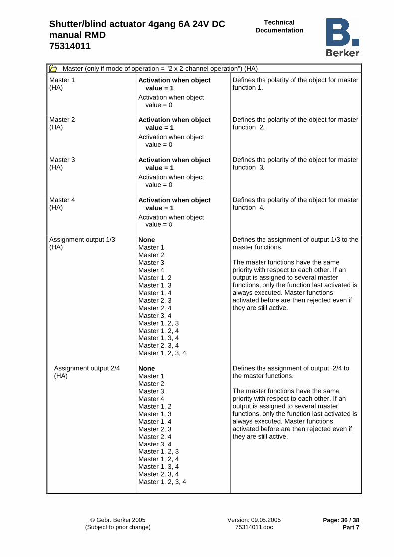
Shutter/blind actuator 4gang 6A 24V DC manual RMD 75314011
Technical Documentation
© Gebr. Berker 2005 Version: 09.05.2005 Page: 36 / 38 (Subject to prior change) 75314011.doc Part 7
Master (only if mode of operation = "2 x 2-channel operation") (HA)
Master 1 (HA)
Activation when object value = 1
Activation when object value = 0
Defines the polarity of the object for master function 1.
Master 2 (HA)
Activation when object value = 1
Activation when object value = 0
Defines the polarity of the object for master function 2.
Master 3 (HA)
Activation when object value = 1
Activation when object value = 0
Defines the polarity of the object for master function 3.
Master 4 (HA)
Activation when object value = 1
Activation when object value = 0
Defines the polarity of the object for master function 4.
Assignment output 1/3 (HA)
None Master 1 Master 2 Master 3 Master 4 Master 1, 2 Master 1, 3 Master 1, 4 Master 2, 3 Master 2, 4 Master 3, 4 Master 1, 2, 3 Master 1, 2, 4 Master 1, 3, 4 Master 2, 3, 4 Master 1, 2, 3, 4
Defines the assignment of output 1/3 to the master functions. The master functions have the same priority with respect to each other. If an output is assigned to several master functions, only the function last activated is always executed. Master functions activated before are then rejected even if they are still active.
Assignment output 2/4 (HA)
None Master 1 Master 2 Master 3 Master 4 Master 1, 2 Master 1, 3 Master 1, 4 Master 2, 3 Master 2, 4 Master 3, 4 Master 1, 2, 3 Master 1, 2, 4 Master 1, 3, 4 Master 2, 3, 4 Master 1, 2, 3, 4
Defines the assignment of output 2/4 to the master functions. The master functions have the same priority with respect to each other. If an output is assigned to several master functions, only the function last activated is always executed. Master functions activated before are then rejected even if they are still active.

Shutter/blind actuator 4gang 6A 24V DC manual RMD 75314011
Technical Documentation
© Gebr. Berker 2005 Version: 09.05.2005 Page: 37 / 38 (Subject to prior change) 75314011.doc Part 7
Response of the blind / shutter at the end of a master function (HA)
Tracking onto position before master function
No change
UP
DOWN
Stop
Defines the response of the blind / shutter at the end of a central function.
At the end of the central function, the position followed up before or during the function is readjusted. If the position cannot be adjusted because it is not known (after mains voltage failure), the response at the end of the central function is firmly set to "moving up".
No reaction. Travel movements unchanged.
The blind moves up at the end of a central function.
The blind moves down at the end of a central function.
The blind stops any travel movements in progress at the end of sun protection.
Master position (only if mode of operation = "2 x 2-channel operation") (HA)
Master 1 Blind / shutter position (0...100 %) (HA)
0 to 100 %, 0
Defines the position of the blind / shutter when central function 1 is active.
Master 1 Lamella position (0..100 %) (HA)
0 to 100 %, 0
Defines the position of the blind / shutter when central function 1 is active.
Only with blind / shutter type = "blind"
Master 2, 3 and 4 Blind / shutter position (0...100 %) (HA)
0 to 100 %, 30 Master 2 0 to 100 %, 60 Master 3 0 to 100 %, 100 Master 4
See Master 1.
Master 2, 3 and 4 Lamella position (0..100 %) (HA)
0 to 100 %, 30 Master 2 0 to 100 %, 60 Master 3 0 to 100 %, 100 Master 4
See Master 1.

Shutter/blind actuator 4gang 6A 24V DC manual RMD 75314011
Technical Documentation
© Gebr. Berker 2005 Version: 09.05.2005 Page: 38 / 38 (Subject to prior change) 75314011.doc Part 7
Manual control
Manual control
enabled
disabled
In the manual control mode it is possible to operate the output channels manually. Manual control works only when mains voltage is available.
Manual control can on principle be activated.
The manual control mode cannot be activated when bus voltage is available.
Manual control on bus voltage failure
enabled
disabled
Manual control can additionally be permitted in the event of bus voltage failure.
The manual control mode can only be activated in the event of bus voltage failure.
Manual control can, on principle, not be activated.
Only with "Manual control" = "Inhibited"!
Software information
• This type of actuator does not permit read-out of bus voltage
• In order to be able to edit all parameters, the access mode in the ETS must be set to "High Access" (HA).