shurjoint®data chart notes ... always refer to the maximum pressure rating and service temperature...
TRANSCRIPT

Shurjoint Piping Products
2015 General C
atalog
// Americas, United States 1380 Beverage Drive, Suite PStone Mountain, GA 30083 USATel.: +1 770 817 0444Fax: +1 770 817 0443
4775 East Cheyenne Ave. Suite 100Las Vegas, NV 89115 USATel.: +1 702 644 4492Fax: +1 702 644 1091 E-mail: [email protected]
// APAC, Taiwan
3F, No. 130, Xinhu 3rd Road (Neihu)Taipei 11494 TaiwanTel.: +886 2 2792 7929Fax: +886 2 2792 5159
// APAC, Singapore
2 Serangoon North Avenue 5 #07-01 Singapore 554911Tel: +65 6577 4360Fax: +65 6481 8791E-mail: [email protected]
// APAC, India
1001, Wing 'C', 10th Floor Godrej Coliseum, SionMumbai 400022 IndiaTel: +91 22 6628 6628Fax: +91 22 6628 6650E-mail: [email protected]
// APAC, Australia
Level 3, 95 Coventry StreetSouthbank, VIC 3006 AustraliaTel: 1300 725 688 (within Australia)Fax: 1300 720 733 (within Australia)E-mail: [email protected]
// Europe, The Netherlands
Kopersteden 1 7547 TJ EnschedeThe NetherlandsTel: +31 (0) 53 428 4444Fax: +31 (0) 53 428 3377E-mail: [email protected]
Your local distributor is:
Shurjoint specifications and or designs are subject to change without notice and or obligation
© Copyright 2015 Shurjoint SJ-2015CAT-201412-EN
2015 General Catalog
SHURJOINT® PIPING PRODUCTS

Contents
Section 1
Grooved Mechanical Couplings, Flange Adapters & Mechanical Tees
Section 2
Cast & Wrought Grooved Fittings
Section 3
Stainless Steel Series
Section 4
Valves & Flow Control Components
Section 5
Threaded Fittings & Welding Outlets
Section 6
Ring Joint, Shouldered & Plain-End Couplings
Section 7
HDPE Series
Section 8
Copper Series
Section 9
AWWA Ductile Iron Series
Section 10
Technical Information
Mechanical Products

Mechanical Products2 Shurjoint Piping Products
Foreword ................................................................................................. 3
Ductile Iron - Housing Material ...................................................... 4
Bolts and Nuts ...................................................................................... 5
Rubber Gasket Compounds ............................................................ 6
Data Chart Notes ................................................................................. 8
Global Pipe Size Designations ....................................................... 9
Specifications, Standards, Codes and Organizations ........ 10
General Information
General Notes
1. Always read and understand all Shurjoint installation instructions before installing any
Shurjoint product.
2. Always depressurize and drain the piping system before attempting disassembly,
adjustment or removal of any piping components.
3. Designers must know and understand all relevant building and or piping standards, codes
and specifications. It is the responsibility of the designer to select and or specify the
appropriate product for the intended use and service.
4. Always refer to the maximum pressure rating and service temperature range allowed for
Shurjoint products and ensure that they are used within these parameters.
5. Special attention is required for selection of suitable gasket grades for the intended service
application.
6. All information and data contained herein supersede all previous published data. Shurjoint
reserves the right to change product designs and or specifications without notice and or
obligation. Please refer to the Shurjoint web site for the latest information.

Mechanical ProductsShurjoint Piping Products 3
Typical Applications HVAC Reverse Osmosis
Fire Protection Desalination
Water Supply & Treatment Mining & Tunnel Boring
Plumbing Marine
Municipal Gas
Food Processing Chemical
Pulp & Paper Oil
Agriculture Air
SHURJOINT
Past to Present The history of Shurjoint dates back to 1974, when the founders produced their first grooved couplings. These first coupl ings were produced f rom malleable iron, the casting material of choice at this time. Before long foundry production was converted to ductile iron. Ductile iron was the ideal material, providing for precision castings and superior strength, without the need for further heat treatment. EPDM (ethylene propylene diene monomer) prov ided a great advancement in synthet ic rubber e las tomer compounds. This new compound offered a service life equal to or in some cases longer than that of carbon steel pipe. EPDM was an ideal gasket material for grooved piping systems.
A World Leader With nearly four decades of experience, Shurjoint is recognized as a world leader in the design and manufacture of mechanical piping components. Shurjoint has developed and currently offers over 3000 individual piping components in sizes from ½” to 96”, for use with a variety of piping materials including carbon steel, stainless steel, ductile iron, PVC, HDPE, CPVC and copper tubing.
In Apri l of 2012 Tyco acquired Shurjoint , broadening its global footprint, grooved product portfolio, and expertise in innovative mechanical solutions. The synergies of joining Tyco and Shurjoint Piping Products offer more value to customers and improved service to the HVAC, plumbing, mining, oil and gas, marine, and industrial markets.
The Shurjoint Mission Our mission is to supply the highest quality products to customers worldwide with an unmatched level of customer service at a superior value. In addition to these ha l lmarks , Shur jo int continuously invests in research, engineering and development, resulting in innovative products and new solutions for the changing needs of industry.
The Shurjoint Catalog This catalog features our general product offering. For the latest and most complete listing of products, news and additional information please visit our website www.shurjoint.com or contact our Customer Service Representative.
A World Leader inMechanical Piping Components
Mechanical couplings were first developed in the 1920's and evolved into Grooved Mechanical Couplings during the 1950's & 60's. This revolution was further spurred in the latter half of the 20th century by advanced engineering and innovative materials such as Ductile Iron and EPDM elastomers.
Taipei 101, 509.2M, the world tallest building 2004 - 2010

Mechanical Products4 Shurjoint Piping Products
Ductile IronSuperior tensile strength
with good castability
Gray IronExcellent castability but ‘brittle’ – less strength
Malleable IronStronger than gray iron
but poor castability
Tensile Yield ASTM Strength, Strength, Elongation Designation min. psi (MPa) min. psi (MPa) in 2”, % Ductile iron castings A536: Gr. 65-45-12 65,000 (448) 45,000 (310) 12 Ductile iron castings A395: Gr. 65-45-15 65,000 (448) 45,000 (310) 15 Forged carbon steel A105 70,000 (485) 40,000 (250) 20 Cast carbon steel A216: WCB 70,000 (485) 36,000 (205) 22 Carbon steel pipe A53: Gr. B 60,000 (415) 35,000 (240) (29.5) Malleable iron castings A47: Gr. 32510 51,000 (345) 32,000 (224) 10 Gray iron castings A126: Gr. B 31,000 (214) Not specified Not specified
Physical strength of materials comparative
Ductile Iron – Housing Material
Ductile iron is an ideal material for grooved mechanical components, as it provides similar or greater strength to that of wrought or cast steel piping materials such as; forged steel flanges - ASTM A105, carbon steel valves - ASTM A216 WCB, wrought carbon steel pipe - ASTM A53 Gr. B, etc. Most Shurjoint components are made of ductile iron conforming to ASTM A536 Gr. 65-45-12 and or ASTM A395 Gr. 65-45-15.
Ductile iron was first invented in the U.S.A. and U.K. in the late 1940's.
Superior strength was achieved by crystallizing graphite in the shape
of nodules. The result was ductile iron that had tensile and yield
strength properties that were equal to or greater than some steel
castings. This superior strength combined with ductile irons excellent
castability helped to reduce the weight and cost of many components.
Because of these advantages and benefits, many components have
been converted from gray iron, malleable iron and steel castings to
ductile iron over the past 60 years. Please visit the Ductile Iron Society
website; www.ductile.org, for further information.
*Reference only as chemical requirements are not specified in ASTM A536.
Chemical Requirements* Minimum Maximum Carbon, % 3.0 3.9 Silicon, % 2.5 3.0 Manganese, % 0.1 0.4 Phosphorus, % 0.07 Sulfur, % 0.02 Magnesium, % 0.03 0.05 Chromium, % 0.1 Physical Properties
Tensile strength, psi (MPa) 65,000 (448) --- Yield strength, psi (MPa) 45,000 (310) --- Elongation, % 12 ---
ASTM A536, Grade 65-45-12 (UNS F33100)
International ductile iron specifications equivalent to
ASTM A536 Gr. 65-45-12 and or ASTM A395 Gr. 65-45-15 are;
SAE J434: D4512
EN1563: EN-GJS-450-10 or EN-GJS-450-15
JIS G5502: FCD450-10
SABS 936/937: SG42
Chemical Requirements Minimum Maximum Carbon, % 3.0 Silicon, % 2.5 Manganese, % Not specified Phosphorus, % 0.08 Sulfur, % Not specified Magnesium, % Not specified Chromium, % Not specified Physical Properties
Tensile strength, psi (MPa) 65,000 (448) --- Yield strength, psi (MPa) 45,000 (310) --- Elongation, % 15 ---
ASTM A395, Grade 65-45-15 (UNS F33100)
Microstructure check
Automatic core Setter
Disamatic Molding LineMax. 360 molds per hour
Sand supply unit
Pattern plate change unit
Precision mold conveyor
Disamatic mold-ing operation
Molten metal pour

Mechanical ProductsShurjoint Piping Products 5
Bolts & Nuts
Carbon steel bolts and nutsShurjoint products utilize oval neck track bolts conforming to
ASTM A449 or ASTM A183 Gr. 2 and heavy duty nuts to ASTM
A563 Gr. B, available with UNC threads or ISO metric threads. The
UNC track bolts and nuts are supplied electro zinc plated in a silver
chromate color and ISO metric bolts and nuts in a gold chromate
color. Hot-dip galvanized bolts and nuts are also available upon
request.
Stainless steel bolts and nutsStainless steel track bolts and nuts, type 304 or type 316, are
supplied with Shurjoint stainless steel couplings. Track bolts and
nuts are molybdenum disulfide (MoS2) coated to inhibit galling. As
an option, silicon bronze nuts are also available to further reduce the
chance of galling.
Chemical Requirements Minimum Maximum Copper, % 96.0 Lead, % 0.05 Iron, % 0.8 Zinc, % 1.5 Magnesium, % 0.7 Silicon, % 0.8 2.0 Physical Properties
Tensile strength, psi (MPa) 55,000 (380) Yield strength, psi (MPa) 20,000 (140) Elongation, % 11 12
Silicon Bronze NutsASTM B98 Alloy B Copper-Silicon Alloy (UNS No. C65100)
A stainless steel bolt fastened with a silicon bronze nut
ASTM A193, Grade B8 (Type 304) Stainless Steel Bolts
Chemical Requirements Minimum Maximum Carbon, % 0.08 Manganese, % 2.00 Phosphorus, % 0.045 Sulfur, % 0.030 Silicon 1.00 Chromium, % 18.00 20.00 Nickel, % 8.00 10.50 Physical Properties
Tensile strength, psi (MPa) 75,000 (515) --- Yield strength, psi (MPa) 30,000 (205) --- Elongation, % 30 ---
ASTM A193, Grade B8M (Type 316) Stainless Steel Bolts Chemical Requirements Minimum Maximum Carbon, % 0.08 Manganese, % 2.00 Phosphorus, % 0.045 Sulfur, % 0.030 Silicon 1.00 Chromium, % 16.00 18.00 Nickel, % 10.00 14.00 Molybdenum 2.00 3.00 Physical Properties
Tensile strength, psi (MPa) 75,000 (515) - Yield strength, psi (MPa) 30,000 (205) - Elongation, % 30 -ASTM A183, Grade 2 Carbon Steel Track Bolts
Chemical Requirements Minimum Maximum Carbon, % 0.30 Phosphorus, % 0.05 Sulfur, % 0.06 Physical Properties
Tensile strength, psi (MPa) 110,000 (760) --- Yield strength, psi (MPa) 80,000 (550) --- Elongation, % 12 ---
ASTM A449, Quenched and Tempered Steel Bolts* Chemical Requirements Minimum Maximum Carbon, % 0.28 0.55 Manganese, % 0.60 Phosphorus, % 0.040 Sulfur, % 0.050 Physical Properties
Tensile strength, psi (MPa) 120,000 (825) -
Yield strength, psi (MPa) 92,000 (635) -
Elongation, % 14 -
*Equivalent to property class 8.8 bolts per ISO 898.
ASTM A563, Grade B Carbon and Alloy Steel Heavy Hex Nuts
Chemical Requirements (bolts) Minimum Maximum Carbon, % 0.55 Phosphorus, % 0.12 Sulfur, % 0.15 Physical Properties
Hardness, Rockwell B69 C32 Recommended Bolt Torque RangeAlways use factory supplied bolts and nuts for assembly of
Shurjoint couplings. Shown below are the general recommended
torque ranges for common sizes of carbon steel bolts. Never exceed
the recommended torque range by more than 25% as excessive
torque can lead to joint failure, personal injury and or property
damage. Always depressurize and drain the piping system before
attempting disassembly, adjustment or removal of any piping
component. Follow installation instructions for proper assembly of all
Shurjoint components. For questions contact Shurjoint.
Bolt Size Proper Torque Range mm in Nm Lbs-Ft M10 ⅜” 40-50 30-40 M12 ½” 120-150 90-110 M16 ⅝” 140-180 100-130 M20 ¾” 200-270 150-200 M22 ⅞” 240-300 180-220 M24 1” 270-340 200-250 - 1⅛” - 225-275
For stainless steel bolts, reduce by 20%

Mechanical Products6 Shurjoint Piping Products
Rubber Gasket Compounds
The 20th century was the era of innovation in plastic and rubber materials. Among the new synthetic rubber compounds that most impacted our industry were EPDM (ethylene propylene diene monomer) and Nitrile rubbers.
Please refer to the Gasket Selection Guide beginning on page 196 for additional information relating to service temperatures and chemical resistance.
EPDM is recognized as the most water resistant rubber
available today. Good for cold & hot water up to 230ºF (110ºC),
waste water, water with acid, deionized water and seawater. EPDM
is not recommended for use with petroleum based oils and fuels,
hydrocarbon solvents and aromatic hydrocarbons.
Shurjoint Grade "E" EPDM is compounded per ASTM D2000
designation 2CA615A25B24F17Z. Peroxide curing and post curing
give a higher crosslink density, which provides a higher aging
resistance than required in AWWA C606.
AWWA C606 Shurjoint 2CA615A25B24F17Z Standard Basic Requirements Hardness, Durometer A, point 65±7 60±5 Tensile strength, psi, min. 1500 psi (10.34 MPa) 1500 psi (10.34 MPa) Elongation, %, min. 300 % 300 % Heat Aging Properties After aged at 212°F After aged at 257°F (100°C) for 70 hours (125°C) for 70 hours Change in Durometer hardness, max. +10 point +5 points Change in tensile strength, max. -25% -10% Change in ultimate elongation, max. -25% -20% Compression Set, Method B, max. 25% 20%
Laboratory high temperature oven testing
Use Shurjoint Grade "E-pw" for potable water and food processing services. The Grade "E-pw" is UL classified per NSF/ANSI 61 and NSF/ANSI 372 for cold +86°F (30°C) and hot +180°F (82°C) potable water services. EPDM seals are recommended for use in breweries as they have the least impact on the characteristics of beer or wort.
Note: EPDM materials used in domestic water applications with high levels of chlorine and or chloramines should be subjected to resistance testing, as not all materials will be suitable. EPDM materials with higher saturated ethylene content and lower carbon black content are recommended for chloramine and chlorine resistance. Contact Shurjoint for further information.
Double Green Stripe
Laboratory hot water testing
Green StripeGrade "E"
Violet StripeGrade "Lube-E"

Mechanical ProductsShurjoint Piping Products 7
NBR, Buna-N, and Nitrile all
represent the same copolymer of butadiene and
acrylonitrile (ACN), which is inherently resistant to
hydraulic fluids, lubricating oils, transmission fluids
and other non-polar petroleum based products
and water less than 150º F (65º C). The higher the
ACN content, the higher the resistance to oils and heat, but the
lower elastic characteristics and compression set. NBR displays poor
resistance to hot water and steam.
Shurjoint grade “T” NBR rubber is compounded based on ASTM
D2000 designation 5BG615A14B24Z and exceeds the requirements
of AWWA C606. Grade “T” is a general purpose compound with
a medium ACN level. For fuels, especially those with a low aniline
point, such as premium or unleaded gasoline, ASTM referenced fuels
B & C and naphtha, use Shurjoint grade “M2” Epichloro-Hydrin or
grade “O” Flurocarbon.
Chloroprene (CR, Neoprene)
Shurjoint Grade "V" chloroprene rubber is a general
purpose elastomer that demonstrates good
resistance to lubricating oils, animal & vegetable
fats and greases. Chloroprene is not effective in
aromatic and oxygenated solvent environments
and is not recommended for hot water and steam
services.
Fluorocarbon (FKM) FKM is a
highly fluorinated carbon backboned compound
and offers excellent resistance to harsh chemical
and ozone attack with a thermal stability to 300°F
(149°C). Shurjoint Grade "O" fluorocarbon gasket
is recommended for use with oils, gasoline,
hydraulic fluids, hydrocarbon solvents and extended fuels that fall
outside the service parameters of grade T / NBR compounds. Not
recommended for steam services.
Epichloro-Hydrin (ECO)
Shurjoint Grade "M2" compound offers good to
excellent resistance to aliphatic hydrocarbon and
aromatic hydrocarbon fuels at low temperatures,
LP gases & fuels, mineral oils and many solvents.
ECO offers limited resistance to many organic
chemicals.
Halogenated Butyl (CIIR)
Shurjoint Grade "M" CIIR is specially compounded
for use with AWWA ductile iron pipe for water
services, mild dilute acids, oil-free air and many
chemicals. The compound is UL classified for
potable water use per NSF/ANSI 61 and NSF/ANSI
372.
AWWA C606 Shurjoint 5BG615A14B24Z Standard Basic Requirements Hardness, Durometer A, point 60±7 60±5 Tensile strength, psi, min. 1500 psi (10.34 MPa) 1500 psi (10.34 MPa) Elongation, %, min. 300 % 300 % When heat aged at 212°F (100°C) for 70 hours Change in Durometer hardness, max. +10 point ±10 points Change in tensile strength, max. -25% -20% Change in ultimate elongation, max. -30% -30% Compression Set, Method B, max. 25% 25%
Use Shurjoint Grade "A" white Nitrile gaskets for
oily and greasy food products and processing,
as well as pharmaceutical and cosmetics
manufacturing. The Grade "A" is compounded
from FDA approved ingredients (CFR Title 21 Part
177.2600).
Use Shurjoint Grade "S" Nitrile gaskets for joints
with AWWA ductile iron pipe. Good for mineral oils,
vegetable oils, air with oil vapors and water less
than 150°F (65°C).
Silicone (VMQ) Shurjoint Grade "L"
Silicone compound features high temperature
range stability and low temperature flexibility.
Recommended for dry heat and air without
hydrocarbons up to 350ºF (177ºC). Silicone
compounds are used in many food and medical
applications as they do not impart odor or taste.
Not recommended for hot water or steam services.
Red Gasket
Yellow Stripe
Blue Stripe
Orange Stripe
White Gasket
Red Stripe
White Stripe
Brown Stripe

Mechanical Products8 Shurjoint Piping Products
Data Chart Notes
I I I I I I I I I I 1 2 3 4 5 6 7 8 9 10
5. Axial Displacement: Designed range of the gap between pipe
ends based on roll grooved pipe.
6. Angular Movement (Deflection): Allowable Axial Displacement
and Angular Movement (deflection) figures are for roll grooved
standard steel pipe. Values for cut grooved pipe will be double
that of roll grooved. These values are maximums; for design
and installation purposes these figures should be reduced by:
50% for ¾”/DN20 – 3½”/DN90; 25% for 4”/DN100 and larger to
compensate for jobsite conditions.
Maximum allowable deflection of pipe from centerline when the
joint is used with cut or roll-grooved steel pipe under no internal
pressure.
7. Dimensions: "A", "B", "C" and so on are external dimensions for
reference purpose only in inches and millimeters.
8. Bolt Size: UNC bolt size and length in inches and ISO metric
bolt size and length in millimeters with numbers of bolts where
applicable.
9. Bolt Torque: Recommended bolt fastening torque in Nm and Lbs-Ft.
10. Weight: Weight of a coupling complete with gasket, bolts and
nuts or of a fitting in kilograms and pounds.
1. Nominal Size: Shurjoint couplings and fittings are identified by
the nominal IPS pipe size in inches or nominal diameter of pipe
(DN) in millimeters. Refer to the chart on the next page which
shows a comparison between typical metric and IPS pipe sizes
2. Pipe O.D.: Actual outside diameter of pipe in inches and
millimeters.
3. Maximum Working Pressure (CWP): Maximum working
pressures listed are CWP (cold water pressure) or maximum
allowed working pressure within the service temperature range of
the gasket used in the coupling, based on standard wall or sch. 40
steel pipe, cut or roll-grooved to ANSI/AWWA C606 (latest edition)
specifications and tested to ASTM F1476. Burst test pressures
are minimum 3 times the maximum working pressures unless
otherwise specified.
These ratings may occasionally differ from maximum working
pressures listed and/or approved by UL, ULC, and/or FM as testing
conditions and test pipes differ. For performance data on other
pipe schedules contact Shurjoint.
Note: For one time field test only the maximum joint working
pressure may be increased 1½ times the figures shown.
4. Maximum End Load: Maximum end loads listed are total of
internal and external forces to which the joint can be subjected,
based on standard wall or sch. 40 steel pipe, cut or roll-grooved to
ANSI/AWWA C606 (latest edition) specifications.
Nominal Pipe Max. Max. Axial Angular Movement Dimensions Bolt Bolt Size O.D. Working End Displacement Degree Per
Pipe Size Torque Weight
Pressure (CWP) Load (CWP) Coupling A B C in in PSI Lbs in
(°) ft / in in in in
in Lbs-Ft Lbs
mm mm Bar kN in / mm mm / m mm mm mm Nm Kgs
Nominal Size / Pipe O.D.
While Shurjoint fittings are normally identified by the nominal
size, always check the actual O.D. of the pipe and fittings to be
connected, as in some markets it is customary to refer to different
O.D. pipes with the same nominal size.
For example: The nominal size 65 (2½") is referred to 73.0 mm
(2.875") pipe O.D. in IPS and 76.1 mm (3.000") pipe O.D. in BS, ISO
or JIS pipes. Refer to pipe & tubing standards for details.
Pipe & Tubing Standards
(ANSI) American National Standards Institute B36.10 & B36.19
(API) American Petroleum Institute API 5L
(ASTM) American Society of Testing and Materials A135, A795 &
B88
(BS) British Standards BS1387, BS3600, BS3601 & BS3605
(ISO) International Standard Organization 65 & 4200
(JIS) Japan Industrial Standard G3452 & G3459

Mechanical ProductsShurjoint Piping Products 9
Nominal Size Outside Diameter (O.D.) Inches DN mm DIN BS ISO JIS ANSI GB India (Imperial) (Metric,mm) (Actual Pipe O.D.) mm mm mm mm in mm IS 1239 IS 3589 ½ 15 21.3 mm DN 15 DN 15 DN 15 21.7 mm ½ DN 15 DN 15 – ¾ 20 26.7 mm 26.9 mm DN 20 DN 20 27.2 mm ¾ DN 20 DN 20 – 1 25 33.4 mm 33.7 mm DN 25 DN 25 34.0 mm 1 DN 25 DN 25 – 1¼ 32 42.2 mm 42.4 mm DN 32 DN 32 42.7 mm 1¼ DN 32 DN 32 – 1½ 40 48.3 mm DN 40 DN 40 DN 40 48.6 mm 1½ DN 40 DN 40 – 2 50 60.3 mm DN 50 DN 50 DN 50 60.5 mm 2 DN 50 DN 50 –
2½ 65 73.1 mm – – – – 2½ – – –
76.1 mm BS/ISO 76.1 mm 76.1 mm 76.1 mm 76.3 mm – 76.1 mm** 76.1 mm – 3 80 88.9 mm DN 80 DN 80 DN 80 DN 80 3 DN 80 DN 80 – 3½ 90 101.6 mm – – – – – – – –
108.0 mm China DIN 133.0 mm – – – – 108.0 mm** – –
4 100 (& old DIN) 114.3 mm DN 100 DN 100 DN 101 DN 100 4 DN 100 DN 100 – -– 127.0 mm 127.0 mm – – – – – – – – 133.0 mm China – – – – – 133.0 mm ** – – 5 125 139.7 mm BS/ISO DN 125 139.7 mm 139.7 mm 139.8 mm – 139.7 mm 139.7 mm – 141.3 mm – – – – 5 – – – -– 152.4 mm 152.4 mm – – – – – – – – 159.0 mm China – – – – – 159.0 mm – 6 150 165.1 mm JIS/BS – 165.1 mm – 165.2 mm – – 165.1 mm – 168.3 mm DN 150 – DN 150 – 6 DN 150 – DN 150 – 6 193.7 mm – – – – – – – 193.7 mm – 203.2 mm 203.2 mm – – – – – – – –
8 200 216.3 mm JIS – – – 216.3 mm – – – –
219.1 mm DN 200 DN 200 DN 200 – 8 DN 200 DN 200 DN 200 – 254.0 mm 254.0 mm – – – – – – – –
10 250 267.4 mm JIS – – – 267.4 mm – – – –
273.0 mm DN 250 DN 250 DN 250 – 10 DN 250 DN 250 DN 250 – 304.8 mm 304.8 mm – – – – – – – –
12 300 318.5 mm JIS – – – 318.5 mm – – – –
323.9 mm DN 300 DN 300 DN 300 – 12 – – –
14 350 355.6 mm DN 350 DN 350 DN 350 DN 350 14 DN 350 – –
377.0 mm China – – – – – 377.0 mm – –
16 400 406.4 mm DN 400 DN 400 DN 400 DN 400 16 DN 400 – –
426.0 mm China – – – – – 426.0 mm – –
18 450 457.2 mm DN 450 DN 450 DN 450 DN 450 18 DN 450 – –
480.0 mm China – – – – – 480.0 mm – –
20 500 508.0 mm DN 500 DN 500 DN 500 DN 500 20 DN 500 – –
530.0 mm China – – – – – 530.0 mm – –
22 550 558.8 mm – – – DN 550 22 559.0 mm – –
580.0 mm China – – – – – 580.0 mm – –
24 600 610.0 mm DN 600 DN 600 DN 600 DN 600 24 DN 600 – –
630.0 mm China – – – – – 630.0 mm – –
Global Pipe Size Designations
Shurjoint product data & technical data are identified by the
nominal IPS pipe size in inches or nominal diameter of pipe (DN) in
millimeters.
Important Note:Nominal designations are used where the actual O.D. of the pipe matches the ANSI size.Otherwise both the nominal and actual O.D. are listed.China sizes are listed as actual O.D. in mm.** China sizes are tubing sizes.
The following chart shows a comparison between typical IPS size
and metric (DIN) sizes.

Mechanical Products10 Shurjoint Piping Products
NYC MEA New York City Department of Buildings, Material & Equipment Acceptance
NYPANew York Power Authority
PEDPressure Equipment Directory 97/23/EC
ULUnderwriter's Laboratories, Inc. - UL213
ULC Underwriter's Laboratories of Canada
TSUSTechnický a Skúýobný Ústav Stavebný, n. o.
VdS VdS Schadenverhütung
Shurjoint production facilities are certified to ISO 9001. Products are
designed to conform and meet or exceed all applicable domestic and
international standards and are listed, approved and or certified by
Specifications, Standards, Codes and Organizations
various approval bodies and registration authorities. Shurjoint is also
active in industry and environmental organizations.
FMFactory Mutual Research Corp. - Approved for Fire Protection Services
FESCJapan Fire Equipment Safety Center
IAPMO R&TIAPMO Research and Testing, Inc.
LLOYDLloyd's Register Quality Assurance ISO 9001:2008
LPCBLoss Prevention Certification Board ISO 9001:2008LPS-1219
NFPANational Fire Protection Association NFPA 13
NSFNSF/ANSI 61 Drinking Water System Components - Health EffectsNSF/ANSI 372 Drinking Water System Components - Lead Content
ANSIAmerican National Standards Institute
ANSI/AWWAAmerican Water Works Association C606 (latest edition)
ASMEAmerican Society of Mechanical EngineersPower Piping, B31.1Building Services Piping, B31.9
ASTMAmerican Society of Testing and MaterialsF 1476-01 CouplingsF 1548-01 FittingsF 1155 Shipbuilding
CNBOP-PIBScientific and Research Centre for Fire Protection - National Research Institute
CSACanadian Standards Association B-242
DLEGState of Michigan Board of Mechanical Rules

Mechanical ProductsShurjoint Piping Products 11
Notes

Mechanical Products12 Shurjoint Piping Products
Notes

Mechanical ProductsShurjoint Piping Products 13
Grooved Mechanical Couplings .................................................. 14
Rigid & Flexible Couplings ............................................................. 15
Z05 Rigid Coupling .............................................................................. 16
K-9 Lightweight Rigid Coupling ........................................................... 17
Z07 Heavy Duty Rigid Coupling ........................................................... 18
Z07N Heavy Duty Rigid Coupling ........................................................ 19
7771 Standard Rigid Coupling ............................................................. 20
XH-1000 Extra Heavy Rigid Coupling .................................................. 21
7705 Flexible Coupling ........................................................................ 22
7707 Heavy Duty Flexible Coupling ..................................................... 23
7707N Flexible Coupling, 14" ~ 26" ..................................................... 24
7707L Large Diameter Coupling .......................................................... 25
7706 Reducing Coupling ..................................................................... 26
G28 Hinged Lever Coupling ................................................................ 27
C-7 Outlet Coupling ............................................................................. 28
7706-T & 7771-T Transition Couplings ................................................ 29
XH-70EP Extra Heavy Rigid Coupling w/EP Gasket ............................ 30
Flange Adapters ................................................................................. 31
7041 Flange Adapter, ANSI Class 125/150 ......................................... 32
7041 Flange Adapter, PN10/16 ........................................................... 33
7041 Flange Adapter, BS 10 Table E .................................................. 34
7043 Flange Adapter ANSI Class 300 ................................................. 34
49 Sandwich Plate ............................................................................... 32
7170 Flange Adapter ANSI Class 125/150 .......................................... 35
7180 & 7181 Universal Flange Adapters ............................................. 36
Mechanical Tees ................................................................................ 37
7721 Mechanical Tee, Female Threaded Outlet ................................. 38
M21 Mechanical Tee, Female Threaded Outlet .................................. 40
7722 Mechanical Tee, Grooved-End Outlet ........................................ 42
M22 Mechanical Tee, Grooved-End Outlet ......................................... 44
723 Saddle-Let .................................................................................... 46
Pressure Performance Data ........................................................... 47
Section 1
Grooved MechanicalCouplings, Flange Adapters & Mechanical Tees

Mechanical Products14 Shurjoint Piping Products
Helpful Information to Ensure Proper
Assembly
Some couplings and components require the housing bolt pads
to make metal-to-metal contact for proper assembly, while others
require a specific bolt torque while maintaining equal bolt pad gaps.
The icons and information below will help to identify those items to
ensure proper assembly. Read and follow all installation instructions
for the component being installed.
Metal-to-metal contact: Tighten bolts and nuts until bolt
pads make metal-to-metal contact. After metal-to-metal contact
is achieved, tighten nuts by another one quarter or one half turn
to make sure the bolts and nuts are snug and secure. No torque
wrench is required. Excessive torque may lead to bolt or joint failure.
Torque required! Bolts and nuts must always be
tightened to the required torque by using a torque wrench. Normally
there will be some gaps seen between the bolt pads after the
bolts and nuts are fully tightened. Bolt pad gaps should
be equal on both sides of the coupling. Models that
require torque tightening include 2” through
4” of model XH-1000, all sizes of models
XH-70EP, SS-7X and 79 couplings.
The Shurjoint grooved piping system is one of the most advanced, versatile, economical and reliable systems available today. After the pipe ends are grooved a gasket is mounted over the pipe ends. The coupling segments are then placed over the gasket and the bolts and nuts are fastened resulting in a secure and leak free joint.
A coupling can be installed 3 – 4 times faster than a comparable
welded or brazed joint and there is no need for a flame or welding
torch on the job site. A grooved mechanical coupling can be installed
by fastening a pair of bolts and nuts while using only a wrench or
spanner, whereas a comparable flanged joint requires the fastening
of many bolts and nuts with a pair of wrenches. The grooved
system allows for easy material take-offs and unlike a threaded
system, there is no need to allow for added pipe length for thread
engagement. With removal of just a few bolts one can easily access
the system for cleaning, maintenance, changes and or system
expansion.
Shurjoint Grooved Mechanical Couplings
No Gap
Metal-to-metal contact After metal-to-metal, further tighten one quarter or half turn
#79 2” ~ 20”#SS-7X 10” ~ 24”
Always use a torque wrench

Mechanical ProductsShurjoint Piping Products 15
Rigid & Flexible Couplings
Grooved mechanical couplings (GMC) are available in both rigid and flexible models. A rigid coupling is used in applications where a rigid joint is desired, similar to that of a traditional flanged, welded, and or threaded connection. To be considered rigid, a coupling would allow less than one degree of deflection or angular movement.
F lexib le coupl ings are designed to
accommodate axial displacement, rotation
and a minimum one degree of angular
movement. Flexible couplings are used in
applications that call for curved or deflected
layouts and or when systems are exposed
to outside forces beyond normal static
conditions, such as seismic events or where
vibration and or noise attenuation are a
concern.
Grooved couplings become less flexible as
the pipe size increases. For sizes in excess
of 18” (450 mm) couplings are very limited
in their angular movement. Please refer to
the following definition and test methods.
Flexibility Proof Test Flexibility proof
testing is conducted by applying a small
bending moment, 10% of the l isted
moment, to the test assembly with no
internal pressure. A 4” model 7705 or 7707
flexible coupling deflects 3 – 4 degrees
depending on the type of groove processed.
Nom. Size , max , max. (inches) (minutes) (degrees) 1½ 57 0.95 2 56 0.93 2½ 55 0.92 3 54 0.90 4 52 0.87 5 50 0.83 6 48 0.80 8 44 0.73 10 40 0.67 12 36 0.60 14 32 0.53 16 28 0.47
Rigid Coupling - Max. Deflection
The rigid coupling shall pass the test when
the angle has not changed more than angle
. shall be calculated as follows: ° = 60’
(minutes) – [2’ (minutes) x (nominal pipe size
in inches)]. In other words, when is less
than 1 degree (60 minutes), the grooved
mechanical coupling is verified as a rigid
coupling and when is more than 1 degree
(60 minutes), the GMC is regarded as a
flexible coupling. The maximum angles for
rigid couplings are shown in the table below:
Nom. Size Moment Moment (inches) Nm Lbs-Ft 1½ 549 405 2 780 575 2½ 1200 885 3 1645 1213 4 2471 1823 5 3551 2619 6 4803 3543 8 7663 5652 10 11379 8393 12 15558 11475 14 18609 13725 16 24299 17922
Test Bending Moment (ASTM F1476)
Definit ion Grooved coupl ings are
subjected to internal pressures and exterior
bending forces during service. ASTM F1476-
07 defines a rigid coupling as a joint where
there is essentially no available free angular
or axial pipe movement and a flexible
coupling as a joint wherein there is available
limited angular and axial pipe movement.
Bending Moment Test bend ing
moments are calculated by the equation M
= F (L), where F is weight of water filled
pipe (Lbs) and L is hanger spacing x 1/2
(feet). The table below shows test bending
moments calculated using sch. 40 pipe with
NFPA 13 hanger spacing.
Rigidity Proof Test Rigidity proof testing
is conducted by applying 25% of the listed
moment to the test assembly which is
internally pressurized to the rated pressure.
Bending Moment Proof Test The
coupling shall resist a 100% listed bending
moment while the assembly is internally
pressurized to the rated pressure.
M= 25% listed moment
Pressurized to ratedpressure
M = 100% listed moment
Pressurized to ratedpressure
M = 10% listed moment
No internalpressure
Hanger Spacing
Water filled pipe
M = F(L)
LL
F
#7705 Flexible Coupling
GasketGroove
Coupling Housing Segment
Bolt / Nut
Coupling Key

Mechanical Products16 Shurjoint Piping Products
Nominal Pipe Max. Max. Axial Dimensions Bolt Size O.D. Working End Displacement † Weight Pressure (CWP)* Load (CWP) A B C No. Size in in PSI Lbs in in in in in Lbs mm mm Bar kN mm mm mm mm mm Kgs 1¼ 1.660 500 1080 0 ~ 0.05 2.60 4.00 1.81
2 ⅜ x 2⅛ 1.41
32 42.2 35 4.89 0 ~ 1.2 66 102 46 M10 x 55 0.64 1½ 1.900 500 1410 0 ~ 0.05 2.83 4.29 1.81
2 ⅜ x 2⅛ 1.46
40 48.3 35 6.41 0 ~ 1.2 72 109 46 M10 x 55 0.66 2 2.375 500 2210 0 ~ 0.07 3.35 4.61 1.85
2 ⅜ x 2¾ 1.74
50 60.3 35 9.99 0 ~ 1.7 85 117 47 M10 x 70 0.79 2½ 2.875 500 3240 0 ~ 0.07 3.86 5.24 1.85
2 ⅜ x 2¾ 2.05
65 73.0 35 14.64 0 ~ 1.7 98 133 47 M10 x 70 0.93
76.1 mm 3.000 500 3530 0 ~ 0.07 3.94 5.35 1.85
2 ⅜ x 2¾ 2.16
76.1 35 15.91 0 ~ 1.7 100 136 47 M10 x 70 0.98 3 3.500 500 4800 0 ~ 0.07 4.45 5.91 1.88
2 ⅜ x 2¾ 2.60
80 88.9 35 21.71 0 ~ 1.7 113 150 48 M10 x 70 1.20
108.0 mm 4.250 500 7080 0 ~ 0.16 5.59 6.93 2.13
2 ⅜ x 2¾ 3.62
108.0 35 32.05 0 ~ 4.1 142 176 54 M10 x 70 1.64 4 4.500 500 7940 0 ~ 0.16 5.75 7.20 2.13
2 ⅜ x 2¾ 4.12
100 114.3 35 35.89 0 ~ 4.1 146 183 54 M10 x 70 1.87
133.0 mm 5.250 350 7570 0 ~ 0.16 6.69 8.82 2.13
2 ½ x 3 5.14
133.0 24 33.33 0 ~ 4.1 170 224 54 M12 x 75 2.33
139.7 mm 5.500 350 8310 0 ~ 0.16 6.81 8.98 2.09
2 ½ x 3 5.67
139.7 24 36.77 0 ~ 4.1 173 228 53 M12 x 75 2.57 5 5.563 350 8500 0 ~ 0.16 6.89 9.06 2.13
2 ½ x 3 5.69
125 141.3 24 37.62 0 ~ 4.1 175 230 54 M12 x 75 2.58
159.0 mm 6.250 350 10730 0 ~ 0.16 7.80 9.84 2.09
2 ½ x 3 6.06
159.0 24 47.63 0 ~ 4.1 198 250 53 M12 x 75 2.75
165.1 mm 6.500 350 11600 0 ~ 0.16 7.87 9.92 2.09
2 ½ x 3 6.72
165.1 24 51.35 0 ~ 4.1 200 252 53 M12 x 75 3.05 6 6.625 350 12050 0 ~ 0.16 8.00 10.0 2.09
2 ½ x 3 6.77
150 168.3 24 53.36 0 ~ 4.1 203 254 53 M12 x 75 3.07 8 8.625 350 20430 0 ~ 0.19 10.40 12.68 2.52
2 ⅝ x 5₅/₁₆ 13.38
200 219.1 24 90.44 0 ~ 4.8 264 322 64 M16 x 135 6.07
200 JIS 8.516 350 19920 0 ~ 0.19 10.24 13.35 2.50
2 ¾ x 4¾ 15.43
216.3 24 88.14 0 ~ 4.8 260 339 64 M20 x 120 7.00
The angle pad design allows for fast
and easy swing-over installation with
the removal of a single bolt.
The Shurjoint Model Z05 is an angle-pad
design rigid coupling for moderate pressure
piping services including fire mains, long
straight runs and valve connections. The
angle-pad design allows the coupling
housings to slide along the bolt pads when
tightened. The result is an offset clamping
action which provides a rigid joint which
Model
Z05 Rigid Coupling- Angle-Pad Design
resists so-called ‘snaking’ of a long straight
run. Support and hanging requirements
correspond to ANSI B31.1, B31.9 and NFPA
13.
With the removal of only one bolt you
can make a fast and easy ‘swing-over’
installation.
* Working Pressure is based on roll grooved standard wall carbon steel pipe. † Allowable Axial Displacement and Angular Movement (deflection) figures are for roll grooved standard steel pipe. Values for cut grooved pipe will be double that of roll grooved. These values are maximums; for
design and installation purposes these figures should be reduced by: 50% for ¾"/DN20 - 3½"/DN90; 25% for 4"/DN100 and larger to compensate for jobsite conditions.
B C
A

Mechanical ProductsShurjoint Piping Products 17
The Shurjoint Model K-9 is a T&G (tongue
& groove) design rigid coupling for moderate
pressure applications where rigidity is
required including valve connections,
mechanical rooms, fire mains and long
Model
K-9 Lightweight Rigid Coupling- T & G Design
Nominal Pipe Max. Max. Axial Dimensions Bolt Size O.D. Working End Displacement Size Weight Pressure (CWP)** Load (CWP) A B C in in PSI Lbs in in in in in Lbs mm mm Bar kN mm mm mm mm mm Kgs 1¼ 1.660 500 1080 0~0.06 2.56 4.33 1.73 ⅜ x 1¾ 1.3 32 42.2 35 4.82 0~1.6 65 110 44 M10 x 45 0.6 1½ 1.900 500 1410 0~0.06 2.80 4.45 1.73 ⅜ x 2⅛ 1.3 40 48.3 35 6.32 0~1.6 71 113 44 M10 x 55 0.6 2 2.375 500 2210 0~0.06 3.27 4.88 1.73 ⅜ x 2⅛ 1.5 50 60.3 35 9.85 0~1.6 83 124 44 M10 x 55 0.7 2½ 2.875 500 3240 0~0.06 3.86 5.39 1.73 ⅜ x 2⅛ 1.8 65 73.0 35 14.43 0~1.6 98 137 44 M10 x 55 0.8
76.1 mm 3.000 500 3530 0~0.06 4.00 5.51 1.73 ⅜ x 2⅛ 1.8
76.1 35 15.68 0~1.6 102 140 44 M10 x 55 0.8 3 3.500 500 4800 0~0.06 4.50 5.94 1.73 ⅜ x 2¾ 2.6 80 88.9 35 21.40 0~1.6 114 151 44 M10 x 70 1.2 4 4.500 350 5560 0~0.13 5.63 7.48 1.97 ⅜ x 2¾ 3.6 100 114.3 24 24.72 0~3.2 143 190 50 M10 x 70 1.7
139.7 mm 5.500 350 8310 0~0.13 6.77 9.21 2.00 ½ x 3 4.6
139.7 24 36.92 0~3.2 172 234 51 M12 x 75 2.1 5 5.563 350 8500 0~0.13 6.89 8.98 1.97 ½ x 3 4.6 125 141.3 24 37.77 0~3.2 175 228 50 M12 x 75 2.1
165.1 mm 6.500 350 11600 0~0.13 7.75 9.92 1.97 ½ x 3 5.3
165.1 24 51.57 0~3.2 197 252 50 M12 x 75 2.4 6 6.625 350 12050 0~0.13 7.87 10.04 2.09 ½ x 3 5.9 150 168.3 24 53.59 0~3.2 200 255 53 M12 x 75 2.7 8 8.625 350 20430 0~0.13 10.16 13.15 2.44 ⅝ x 3½ 9.7 200 219.1 24 90.82 0~3.2 258 334 62 M16 x 90 4.4 8 (K-9H) 8.625 350 20430 0~0.13 10.29 13.08 2.44 ¾ x 4¾ 15.8 200 219.1 24 90.82 0~3.2 261 332 62 M20 x 120 7.2
straight runs. The built-in teeth and T&G
mechanism firmly grasp the pipe ends
to eliminate undesired flex. Support and
hanging requirements correspond to ANSI
B31.1, B31.9 and NFPA 13.
All DIN size K-9 couplings up to DN150 size and the DN200 K-9H coupling are VdS approved in addition to cULus and FM approvls.** Working Pressure is based on roll grooved standard wall carbon steel pipe.
B C
A
No need to worry about bolt pad interference as the Model K-9 works well with both regular and short-radius elbows and tees.
Nointerference

Mechanical Products18 Shurjoint Piping Products
A
B C
housings to slide along the bolt pads when
tightened. The result is an offset clamping
action which provides a rigid joint that resists
flexural and torsional loads. Support and
hanging requirements correspond to ANSI
B31.1, B31.9 and NFPA 13.
The Shurjoint Model Z07 is an angle-pad
design rigid coupling for general piping
applications where rigidity is required
including, mechanical rooms, valve
connections fire mains and long straight runs.
The angle-pad design allows the coupling
Model
Z07 Heavy Duty Rigid Coupling
* Working Pressure is based on roll grooved standard wall carbon steel pipe. † Allowable Axial Displacement and Angular Movement (deflection) figures are for roll grooved standard steel pipe. Values for cut grooved pipe will be double that of roll grooved. These values are maximums; for
design and installation purposes these figures should be reduced by: 50% for ¾" - 3½"; 25% for 4" and larger to compensate for jobsite conditions.
Nominal Pipe Max. Max. Axial Dimensions Bolt Size O.D. Working End Displacement † Weight Pressure (CWP)* Load (CWP) A B C No. Size in in PSI Lbs in in in in in Lbs mm mm Bar kN mm mm mm mm mm Kgs 1¼ 1.660 750 1620 0 ~ 0.05 2.68 4.13 1.85
2 ⅜ x 2⅛ 1.6
32 42.2 52 7.27 0~1.2 68 105 47 M10 x 55 0.7 1½ 1.900 750 2120 0 ~ 0.05 2.91 4.53 1.85
2 ⅜ x 2⅛ 2.0
40 48.3 52 9.52 0~1.2 74 115 47 M10 x 55 0.9 2 2.375 750 3320 0 ~ 0.07 3.39 4.69 1.88
2 ⅜ x 2¾ 2.4
50 60.3 52 14.84 0~1.7 86 119 48 M10 x 70 1.1 2½ 2.875 750 4860 0 ~ 0.07 3.94 5.50 1.88
2 ⅜ x 2¾ 2.4
65 73.0 52 21.75 0~1.7 100 140 48 M10 x 70 1.1
76.1 mm 3.000 750 5290 0 ~ 0.07 4.00 5.75 1.88
2 ⅜ x 2¾ 2.4
76.1 52 23.64 0~1.7 102 146 48 M10 x 70 1.1 3 3.500 750 7210 0 ~ 0.07 4.53 6.54 1.88
2 ½ x 3 3.1
80 88.9 52 32.26 0~1.7 115 166 48 M12 x 75 1.4 4 4.500 750 11920 0 ~ 0.16 5.78 8.11 2.13
2 ½ x 3 4.4
100 114.3 52 53.33 0~4.1 147 206 54 M12 x 75 2.0
139.7 mm 5.500 750 17810 0 ~ 0.16 6.88 9.37 2.09
2 ⅝ x 3½ 6.6
139.7 52 79.66 0~4.1 175 238 53 M16 x 90 3.0 5 5.563 750 18220 0 ~ 0.16 6.97 9.45 2.09
2 ⅝ x 3½ 6.6
125 141.3 52 81.50 0~4.1 177 240 53 M16 x 90 3.0
165.1 mm 6.500 700 23210 0 ~ 0.16 7.87 10.47 2.09
2 ⅝ x 3½ 7.5
165.1 48 102.71 0~4.1 200 266 53 M16 x 90 3.4 6 6.625 700 24110 0 ~ 0.16 8.00 10.67 2.09
2 ⅝ x 3½ 7.1
150 168.3 48 106.73 0~4.1 203 271 53 M16 x 90 3.2 8 8.625 600 35030 0 ~ 0.19 10.55 13.46 2.52
2 ¾ x 4¾ 15.7
200 219.1 42 158.27 0~4.8 268 342 64 M20 x 120 7.1 10 10.750 500 45350 0 ~ 0.13 12.86 15.60 2.56
2 ⅞ x 6½ 27.4
250 273.0 35 204.77 0~3.2 327 396 65 --- 10.4 12 12.750 400 51040 0 ~ 0.13 14.86 17.80 2.56
2 ⅞ x 6½ 26.0
300 323.9 28 230.59 0~3.2 377 452 65 --- 11.8
200 JIS 8.516 600 34150 0 ~ 0.13 10.39 13.35 2.50
2 ¾ x 4¾ 16.3
216.3 42 154.25 0~3.2 264 339 64 M20 x 120 7.4
250 JIS 10.528 500 43500 0 ~ 0.13 12.63 15.63 2.56
2 ⅞ x 6½ 23.1
267.4 35 196.45 0~3.2 321 397 65 --- 10.5
300 JIS 12.539 400 49360 0 ~ 0.13 14.65 17.80 2.56
2 ⅞ x 6½ 27.4
318.5 28 222.97 0~3.2 372 452 65 --- 12.4

Mechanical ProductsShurjoint Piping Products 19
A
B C
Model
Z07N Heavy Duty Rigid Coupling
The Shurjoint Model Z07N is a two-
segment, rigid coupling for general piping
applications where rigidity is required. Sizes
14" - 24" are now available.
* Working Pressure is based on roll grooved standard wall carbon steel pipe.† Allowable Axial Displacement and Angular Movement (deflection) figures are for roll grooved standard steel pipe. Values for cut grooved pipe will be double that of roll grooved. These values are maximums; for design and installation purposes these figures should be reduced by: 50% for ¾" - 3½"; 25% for 4" and larger to compensate for jobsite conditions.
Nominal Pipe Max. Max. Axial Dimensions Bolt Size O.D. Working End Displacement † Weight Pressure (CWP)* Load (CWP) A B C No. Size in in PSI Lbs in in in in in Lbs mm mm Bar kN mm mm mm mm mm Kgs 14 14.000 250 38460 0 ~ 0.13 16.06 20.00 2.95
2 ⅞ x 5½ 35.3
350 355.6 17 168.75 0~3.2 408 508 75 --- 16.0 16 16.000 250 50240 0 ~ 0.13 18.39 22.05 2.95
2 ⅞ x 5½ 30.5
400 406.4 17 220.41 0~3.2 467 660 75 --- 17.9 18 18.000 250 63580 0 ~ 0.13 20.68 24.29 3.11
2 ⅞ x 5½ 40.1
450 457.2 17 278.95 0~3.2 525 617 79 --- 22.3 20 20.000 250 78500 0 ~ 0.13 22.93 27.99 3.00
2 1 x 5½ 57.8
500 508.0 17 344.39 0~3.2 582 711 76 --- 26.2 24 24.000 250 113040 0 ~ 0.13 27.05 30.55 3.06
2 1 x 5½ 70.8
600 609.6 17 495.92 0~3.2 687 776 78 --- 32.1

Mechanical Products20 Shurjoint Piping Products
B C
14”~ 18”20”~ 24”
AA
A
B C
B C
1½”~ 12”
The Shurjoint Model 7771 is a T&G (tongue
& groove) design standard rigid coupling for
general piping applications where rigidity
is required including valve connections,
mechanical rooms, fire mains and long
straight runs. The T&G mechanism provides
a rigid, locked-in connection that resists
flexural and torsional loads. Support and
hanging requirements correspond to ANSI
B31.1, B31.9 and NFPA 13.
Model
7771 Standard Rigid Coupling- T & G Design
** Working Pressure is based on roll grooved standard wall carbon steel pipe. † Allowable Axial Displacement and Angular Movement (deflection) figures are for roll grooved standard steel pipe. Values for cut grooved pipe will be double that of roll grooved. These values are maximums; for
design and installation purposes these figures should be reduced by: 50% for ¾" - 3½"; 25% for 4" and larger to compensate for jobsite conditions.
Nominal Pipe Max. Max. Axial Dimensions Bolt Size O.D. Working End Displacement † Weight Pressure (CWP)** Load (CWP) A B C No. Size in in PSI Lbs in in in in in Lbs mm mm Bar kN mm mm mm mm mm Kgs 1½ 1.900 500 1410 0~0.06 2.91 4.41 1.81
2 ⅜ x 2⅛ 1.5
40 48.3 35 6.23 0~1.6 74 112 46 M10 x 55 0.7 2 2.375 500 2210 0~0.06 3.34 4.96 1.81
2 ⅜ x 2⅛ 1.9
50 60.3 35 9.70 0~1.6 85 126 46 M10 x 55 0.9 2½ 2.875 500 3240 0~0.06 3.89 5.59 1.81
2 ⅜ x 2⅛ 2.6
65 73.0 35 14.22 0~1.6 99 142 46 M10 x 55 1.2
76.1 mm 3.000 500 3530 0~0.06 4.00 5.90 1.81
2 ⅜ x 2⅛ 2.6
76.1 35 15.46 0~1.6 102 150 46 M10 x 55 1.2 3 3.500 500 4800 0~0.06 4.52 6.50 1.81
2 ½ x 3 3.3
80 88.9 35 21.09 0~1.6 115 165 46 M12 x 75 1.5
108.0 mm 4.250 500 7090 0~0.16 5.54 7.59 2.00
2 ½ x 3 4.8
108.0 35 31.13 0~4.1 141 193 51 M12 x 75 2.2 4 4.500 500 7940 0~0.16 5.82 7.79 2.00
2 ½ x 3 4.8
100 114.3 35 34.87 0~4.1 148 198 51 M12 x 75 2.2
133.0 mm 5.250 450 9730 0~0.16 6.61 9.72 2.00
2 ⅝ x 3½ 6.0
133.0 31 43.05 0~4.1 168 247 51 M16 x 90 2.7
139.7 mm 5.500 450 10680 0~0.16 6.8 9.45 2.00
2 ⅝ x 3½ 6.4
139.7 31 47.49 0~4.1 173 240 51 M16 x 90 2.9 5 5.563 450 10930 0~0.16 6.88 9.84 2.00
2 ⅝ x 3½ 6.4
125 141.3 31 48.59 0~4.1 175 250 51 M16 x 90 2.9
165.1 mm 6.500 450 14920 0~0.16 7.87 11.02 2.09
2 ⅝ x 3½ 7.7
165.1 31 66.33 0~4.1 200 280 53 M16 x 90 3.5 6 6.625 450 15500 0~0.16 8.07 11.18 2.09
2 ⅝ x 3½ 8.1
150 168.3 31 68.93 0~4.1 205 284 53 M16 x 90 3.7 8 8.625 300 17510 0~0.16 10.27 13.58 2.48
2 ⅝ x 5 14.6
200 219.1 20 75.37 0~4.1 261 345 63 M16 x 135 6.6 10 10.750 300 27210 0~0.16 12.44 15.51 2.50
2 ¾ x 4¾ 18.6
250 273.0 20 117.01 0~4.1 316 394 64 M20 x 120 8.4 12 12.750 300 38280 0~0.16 14.17 14.06 2.50
2 ⅞ x 6½ 24.5
300 323.9 20 164.71 0~4.1 360 357 64 --- 11.1
200 JIS 8.516 300 17070 0~0.16 10.00 13.58 2.48
2 ⅝ x 5 15.2
216.3 20 73.45 0~4.1 254 345 63 M16 x 135 6.9
250 JIS 10.528 300 26100 0~0.16 12.20 15.20 2.50
2 ¾ x 4¾ 19.3
267.4 20 112.26 0~4.1 310 386 64 M20 x 120 8.7
300 JIS 12.539 300 37020 0~0.16 13.94 17.48 2.50
2 ⅞ x 6½ 26.0
318.5 20 159.26 0~4.1 354 444 64 --- 11.2 14 14.000 300 46150 0~0.13 16.25 20.28 2.95
2 ⅞ x 4 31.9
350 355.6 20 198.53 0~3.2 413 515 75 --- 14.5 16 16.000 300 60280 0~0.13 18.11 22.17 2.95
3 ⅞ x 4 35.2
400 406.4 20 259.30 0~3.2 460 563 75 --- 16.0 18 18.000 300 76300 0~0.13 20.51 24.21 3.11
3 ⅞ x 4 37.4
450 457.2 20 328.18 0~3.2 521 615 79 --- 17.0 20 20.000 300 94200 0~0.13 22.87 26.26 3.11
4 1 x 3½ 52.8
500 508.0 20 405.16 0~3.2 581 667 79 --- 24.0 22 22.000 250 94980 0~0.13 24.49 28.35 3.11
4 1 x 3½ 58.3
550 558.8 17 416.71 0~3.2 622 720 79 --- 26.5 24 24.000 250 113040 0~0.13 27.12 30.24 3.11
4 1 x 3½ 62.6
600 609.6 17 495.92 0~3.2 689 768 79 --- 28.4

Mechanical ProductsShurjoint Piping Products 21
cut grooved pipes or components. Sizes 2”
through 4” require a bolt torque of 60 - 70
Lbs-Ft. with some bolt gaps. For sizes 6”
and above, the bolt pads will make metal to
metal contact when properly installed with
no torque wrench required.
Sizes 2” through 4” require a bolt torque of
60 – 70 Lbs-Ft (80 – 95 Nm). Normally you
can see some gaps between the bolt pads.
Bolt pad gaps should be equal on both sides
of the coupling.
Sizes 6” through 12” are designed to make
a metal-to-metal contact when properly
installed.
The Shurjoint Model XH-1000 is an extra
heavy rigid coupling designed for high
pressure services up to 1000 psi (70 Bar).
This coupling is painted orange and is
supplied with a standard C-shaped gasket
and heavy duty bolts and nuts. The Model
XH-1000 can be installed on standard roll or
Model
XH-1000 Extra Heavy Rigid Coupling
B C
A
* Working Pressure is based on roll grooved standard wall carbon steel pipe. † Allowable Axial Displacement and Angular Movement (deflection) figures are for roll grooved standard steel pipe. Values for cut grooved pipe will be double that of roll grooved. These values are maximums; for
design and installation purposes these figures should be reduced by: 50% for ¾" - 3½"; 25% for 4" and larger to compensate for jobsite conditions.
Nominal Pipe Max. Max. Axial Dimensions Bolt Size O.D. Working End Displacement † Weight Pressure (CWP)* Load (CWP) A B C No. Size in in PSI Lbs in in in in
in Lbs
mm mm Bar kN mm mm mm mm Kgs 2 2.375 1000 4420 0 ~ 0.14 3.50 5.71 1.92
2 ⅝ x 2¾ 3.4
50 60.3 69 19.98 0 ~ 3.6 90 145 49 1.6 2½ 2.875 1000 6480 0 ~ 0.14 4.02 6.61 1.92
2 ⅝ x 2¾ 3.8
65 73.0 69 29.28 0 ~ 3.6 102 168 49 1.7 3 3.500 1000 9610 0 ~ 0.14 4.86 7.40 1.92
2 ⅝ x 2¾ 4.8
80 88.9 69 43.43 0 ~ 3.6 123 188 49 2.2 4 4.500 1000 15890 0 ~ 0.25 6.09 8.74 2.10
2 ¾ x 4¾ 8.4
100 114.3 69 71.79 0 ~ 6.4 155 222 53 3.8 6 6.625 1000 34450 0 ~ 0.25 8.58 11.61 2.25
2 ⅞ x 5⅛ 17.6 150 168.3 69 155.65 0 ~ 6.4 218 295 57 8.0 8 8.625 800 46710 0 ~ 0.25 10.83 14.33 2.75
2 1 x 5½ 24.0
200 219.1 55 207.26 0 ~ 6.4 275 364 70 10.9 10 10.750 800 72570 0 ~ 0.25 13.15 16.70 2.95
2 1 x 5½ 31.2
250 273.0 55 321.78 0 ~ 6.4 334 424 75 14.2 12 12.750 800 102080 0 ~ 0.25 15.35 18.90 2.95
2 1 x 5½ 36.7
300 323.9 55 452.95 0 ~ 6.4 390 480 75 16.7

Mechanical Products22 Shurjoint Piping Products
The Shurjoint Model 7705 is a standard
flexible coupling designed for use in a
variety of moderate pressure general piping
applications. The Model 7705 coupling
features flexibility that can accommodate
misalignment, distortion, thermal stress,
vibration, noise and seismic tremors. The
Model 7705 can even accommodate an
arced or curved piping layout. See Typical
Applications - Flexible Couplings on page
191.
Model
7705 Flexible Coupling
A
B C
Nominal Pipe Max. Max. Axial Angular Movement**† Dimensions Bolt Size O.D. Working End Displace- Degree Per Per Size Weight Pressure (CWP)* Load (CWP) ment † Coupling Pipe A B C in in PSI Lbs in
(°) in/ft in in in in Lbs
mm mm Bar kN mm mm/m mm mm mm mm Kgs 1 1.315 500 670 0.0625
2° - 45’ 0.58 2.24 3.94 1.81 ⅜ x 1¾ 1.3
25 33.4 35 3.12 1.6 48 57 100 46 M10 x 45 0.6 1¼ 1.660 500 1080 0.0625
2° - 10’ 0.46 2.60 4.06 1.81 ⅜ x 2⅛ 1.5
32 42.2 35 4.94 1.6 38 66 103 46 M10 x 55 0.7 1½ 1.900 500 1410 0.0625
1° - 54’ 0.4 2.83 4.25 1.81 ⅜ x 2⅛ 1.6
40 48.3 35 6.41 1.6 33 72 108 46 M10 x 55 0.7 2 2.375 500 2210 0.0625
1° - 31’ 0.32 3.31 5.08 1.85 ⅜ x 2⅛ 1.8
50 60.3 35 9.99 1.6 27 84 129 47 M10 x 55 0.8 2½ 2.875 500 3240 0.0625
1° - 15’ 0.26 3.90 5.59 1.85 ⅜ x 2⅛ 2.0
65 73.0 35 14.64 1.6 22 99 142 47 M10 x 55 0.9
76.1 mm 3.000 500 3530 0.0625
1° - 12’ 0.25 4.02 5.79 1.85 ⅜ x 2⅛ 2.1
76.1 35 15.91 1.6 21 102 147 47 M10 x 55 1.0 3 3.500 500 4800 0.0625
1° - 02’ 0.22 4.57 6.46 1.85 ½ x 3 2.8
80 88.9 35 21.71 1.6 18 116 164 47 M12 x 75 1.3
101.6 mm 4.000 500 6280 0.0625
0° - 54’ 0.19 5.07 7.24 1.85 ½ x 3 3.6
101.6 35 28.36 1.6 16 129 184 47 M12 x 75 1.6
108.0 mm 4.250 500 7080 0.1250
1° - 42’ 0.36 5.43 7.56 2.05 ½ x 3 4.1
108.0 35 32.05 3.2 30 138 192 52 M12 x 75 1.9 4 4.500 500 7940 0.1250
1° - 36’ 0.34 5.71 7.76 2.05 ½ x 3 4.1
100 114.3 35 35.89 3.2 28 145 197 52 M12 x 75 1.9
133.0 mm 5.250 450 9730 0.1250
1° - 23’ 0.29 6.50 9.09 2.05 ⅝ x 3½ 5.1
133.0 31 43.05 3.2 24 165 231 52 M16 x 90 2.3
139.7 mm 5.500 450 10680 0.1250
1° - 18’ 0.28 6.69 9.76 2.05 ⅝ x 3½ 5.9
139.7 31 47.49 3.2 23 170 248 52 M16 x 90 2.7 5 5.563 450 10930 0.1250
1° - 18’ 0.27 6.77 9.17 2.05 ⅝ x 3½ 5.9
125 141.3 31 48.59 3.2 23 172 233 52 M16 x 90 2.7
159.0 mm 6.250 450 13790 0.1250
1° - 09’ 0.24 7.48 9.96 2.05 ⅝ x 3½ 6.6
159.0 31 61.52 3.2 20 190 253 52 M16 x 90 3.0
165.1 mm 6.500 450 14920 0.1250
1° - 07’ 0.24 7.72 10.28 2.09 ⅝ x 3½ 6.8
165.1 31 66.33 3.2 20 196 261 53 M16 x 90 3.1 6 6.625 450 15500 0.1250
1° - 05’ 0.23 7.87 10.55 2.09 ⅝ x 3½ 7.0
150 168.3 31 68.93 3.2 19 200 268 53 M16 x 90 3.2 8 8.625 300 17510 0.1250
0° - 50’ 0.18 10.24 13.27 2.44 ⅝ x 3½ 12.8
200 219.1 20 75.37 3.2 15 260 337 62 M16 x 90 5.8 8 (7705H) 8.625 450 26270 0.1250
0° - 50’ 0.18 10.47 13.07 2.44 ¾ x 4¾ 15.7
200 219.1 31 116.82 3.2 15 266 332 62 M20 x 120 7.1 10 10.750 300 27210 0.1250
0° - 40’ 0.14 13.50 13.78 2.56 ¾ x 4¾ 18.0
250 273.0 20 117.01 3.2 12 343 350 65 M20 x 120 8.2 12 12.750 300 38280 0.1250
0° - 34’ 0.12 15.35 15.75 2.56 ⅞ x 6½ 23.8
300 323.9 20 164.71 3.2 10 390 400 65 --- 10.8
200 JIS 8.516 300 17079 0.1250
0° - 51’ 0.18 10.00 13.70 2.36 ¾ x 4¾ 12.8
216.3 20 73.45 3.2 15 254 348 60 M20 x 120 5.8
250 JIS 10.528 300 26103 0.1250
0° - 41’ 0.15 13.27 15.28 2.56 ¾ x 4¾ 17.6
267.4 20 112.26 3.2 12 337 388 65 M20 x 120 8.0
300 JIS 12.539 300 37027 0.1250
0° - 35’ 0.12 15.31 17.48 2.56 ⅞ x 6½ 22.6
318.5 20 159.26 3.2 10 389 444 65 --- 10.3
All DIN size 7705 couplings up to DN150 size and the DN200 7705H coupling are VdS approved in addition to cULus and FM approvals. * Working Pressure is based on roll grooved standard wall carbon steel pipe.† Allowable Axial Displacement and Angular Movement (deflection) figures are for roll grooved standard steel pipe. Values for cut grooved pipe will be double that of roll grooved. These values are maximums; for
design and installation purposes these figures should be reduced by: 50% for ¾"/DN20 - 3½"/DN90; 25% for 4"/DN100 and larger to compensate for jobsite conditions. ** Deflection or angular movement is the maximum value that a coupling allows under no internal pressure.

Mechanical ProductsShurjoint Piping Products 23
the wall thickness and rating of the pipe
being used. The Model 7707 couplings
feature flexibility that can accommodate
misalignment, distortion, thermal stress,
vibration, noise and seismic tremors. The
The Shurjoint Model 7707 heavy duty
flexible coupling is designed for use in a
variety of general piping applications
of moderate or high pressure services.
Working pressure is usually dictated by
Model
7707 Heavy Duty Flexible Coupling
Model 7707 can even accommodate an
arced or curved piping layout. See Typical
Applications - Flexible Couplings on page
191.
B C
A
¾"~12"
** Working Pressure is based on roll grooved standard wall carbon steel pipe. † Allowable Axial Displacement and Angular Movement (deflection) figures are for roll grooved standard steel pipe. Values for cut grooved pipe will be double that of roll grooved. These values are maximums; for
design and installation purposes these figures should be reduced by: 50% for ¾" - 3½"; 25% for 4" and larger to compensate for jobsite conditions. ‡ Deflection or angular movement is the maximum value that a coupling allows under no internal pressure. * Non-standard/stock items may require longer lead time.
Nominal Pipe Max. Working Max. Axial Angular Movement ‡† Dimensions Bolts Size O. D. Pressure End Displacement † Degree Per Per Weight (CWP)** Load (CWP) Coupling Pipe A B C No. Size in in PSI Lbs in
(°) in / ft in in in in Lbs
mm mm Bar kN mm mm / m mm mm mm mm Kgs ¾* 1.050 1000 865 0.0625
3° – 23’ 0.71 2.13 3.74 1.81
2 ⅜ x 2⅛ 1.3
20 26.7 69 3.79 1.6 58 54 95 46 M10x55 0.6 1 1.315 1000 1360 0.0625
2° – 45’ 0.58 2.40 4.02 1.81
2 ⅜ x 2⅛ 1.7
25 33.4 69 6.15 1.6 48 61 102 46 M10x55 0.8 1¼ 1.660 1000 2160 0.0625
2° – 10’ 0.45 2.76 4.45 1.81
2 ½ x 3 2.1
32 42.2 69 9.64 1.6 38 70 113 46 M12x75 1.0 1½ 1.900 1000 2830 0.0625
1° – 54’ 0.40 3.00 4.57 1.81
2 ½ x 2⅜ 2.1
40 48.3 69 12.64 1.6 33 76 116 46 M12x60 1.0 2 2.375 1000 4430 0.0625
1° – 31’ 0.31 3.50 5.35 1.81
2 ½ x 3 2.6
50 60.3 69 19.69 1.6 26 90 136 46 M12x75 1.2 2½ 2.875 1000 6490 0.0625
1° – 15’ 0.26 4.00 5.98 1.85
2 ½ x 3 2.9
65 73.0 69 28.86 1.6 22 102 152 47 M12x75 1.3
76.1 mm 3.000 1000 7065 0.0625
1° – 12’ 0.25 4.06 6.02 1.85
2 ½ x 3 2.9
76.1 69 31.37 1.6 21 103 153 47 M12x75 1.3 3 3.500 1000 9620 0.0625
1° – 02’ 0.21 4.88 6.34 1.85
2 ½ x 3 3.3
80 88.9 69 42.81 1.6 18 124 161 47 M12x75 1.5 4 4.500 1000 15900 0.1250
1° – 36’ 0.33 6.18 8.03 2.05
2 ⅝ x 3½ 4.6
100 114.3 69 70.76 3.2 27 157 204 52 M16x90 2.1
139.7 mm 5.500 1000 23750 0.1250
1° – 18’ 0.27 7.32 9.41 2.09
2 ⅝ x 3½ 6.8
139.7 69 105.71 3.2 23 186 239 53 M16x90 3.1 5 5.563 1000 24295 0.1250
1° – 18’ 0.27 7.32 9.65 2.09
2 ⅝ x 3½ 7.2
125 141.3 69 108.14 3.2 22 186 245 53 M16x90 3.3
165.1 mm 6.500 1000 33170 0.1250
1° – 07’ 0.23 8.11 10.24 2.09
2 ¾ x 4¾ 7.9
165.1 69 147.64 3.2 19 211 260 53 M20x120 3.6 6 6.625 1000 34455 0.1250
1° – 05’ 0.22 8.24 10.75 2.09
2 ¾ x 4¾ 8.1
150 168.3 69 153.42 3.2 19 214 273 53 M20x120 3.7 8 8.625 800 46720 0.1250
0° – 50’ 0.18 10.86 13.23 2.44
2 ¾ x 4¾ 14.5
200 219.1 55 207.26 3.2 15 276 336 62 M20x120 6.6 10 10.750 800 72575 0.1250
0° – 40’ 0.14 13.50 16.10 2.56
2 ⅞ x 6½ 23.3
250 273.0 55 321.78 3.2 11 343 409 65 --- 10.6 12 12.750 800 102090 0.1250
0° – 34’ 0.12 15.35 18.50 2.60
2 ⅞ x 6½ 26.4
300 323.9 55 452.95 3.2 10 390 470 66 --- 12.0
200 JIS 8.516 800 45545 0.1250
0° – 51’ 0.18 10.86 13.03 2.36
2 ¾ x 4¾ 13.9
216.3 55 202.00 3.2 15 276 331 60 M20x120 6.3
250 JIS 10.528 800 69610 0.1250
0° – 41’ 0.14 13.27 15.87 2.60
2 ⅞ x 6½ 22.4
267.4 55 308.71 3.2 12 337 403 66 --- 10.2
300 JIS 12.539 800 98740 0.1250
0° – 35’ 0.12 15.31 18.11 2.60
2 ⅞ x 6½ 25.5
318.5 55 437.98 3.2 10 389 460 66 --- 11.6

Mechanical Products24 Shurjoint Piping Products
The Shurjoint Model 7707N is a two-
segment, flexible coupling for use with
standard pipe, roll or cut grooved to AWWA
C606 specifications. For 26", see page 189
for groove dimensions.
Model
7707N Flexible Coupling
26"14" ~ 24"
B C
A
26”
* Working pressure is based on roll-grooved standard wall carbon steel pipe.Pressure ratings are based on cut-grooved XS carbon steel pipe, refer to page 51 on STD & LW carbon steel pipes.† Allowable Axial Displacement and Angular Movement (deflection) figures are for roll grooved standard steel pipe. Values for cut grooved pipe will be double that of roll grooved. These values are maximums; for
design and installation purposes these figures should be reduced by: 50% for ¾" - 3½"; 25% for 4" and larger to compensate for jobsite conditions. ** Deflection or angular movement is the maximum value that a coupling allows under no internal pressure.
14”~ 24”
B C
A
Max. Max. Axial Angular Movement**† Dimensions Bolt Nominal Pipe Working End Displacement † Degree Per Weight Size O.D. Pressure (CWP)* Load (CWP) Coupling Per Pipe A B C No. Size in in PSI Lbs in
(°) in / ft in in in
in Lbs
mm mm Bar kN mm mm / m mm mm mm Kgs 14 14.00 300 46150 0.125
0° – 31’ 0.06 16.23 19.80 2.95
2 ⅞ x 6½ 34.5
350 355.6 20 198.53 3.2 4.5 412.0 503.0 75.0 15.7 16 16.00 300 60280 0.125
0° – 27’ 0.05 18.23 21.85 2.95
2 1 x 6½ 37.0
400 406.4 20 259.30 3.2 4.0 463.0 555.0 75.0 16.8 18 18.00 300 76300 0.125
0° – 24’ 0.04 20.45 24.06 3.11
2 1 x 6½ 47.1
450 457.2 20 327.89 3.2 3.5 520.0 611.0 79.0 22.3 20 20.00 300 94200 0.125
0° – 22’ 0.04 22.48 26.38 3.11
2 1 x 6½ 54.4
500 508.0 20 405.16 3.2 3.0 571.0 670.0 79.0 24.7 22 22.00 300 113980 0.125
0° – 19’ 0.04 24.46 30.16 3.11
2 1⅛ x 6½ 63.0
550 558.8 20 490.60 3.2 3.0 621.4 766.0 79.0 28.6 24 24.00 300 135640 0.125
0° – 18’ 0.03 26.55 30.43 3.11
2 1⅛ x 6½ 65.1
600 609.6 20 584.20 3.2 2.5 674.0 773.0 79.0 29.5 26 26.00 300 159190 0.125
0° – 17’ 0.03 29.68 33.15 4.94
4 ⅞ x 9⅝ 143.0 650 660.4 20 684.72 3.2 2.5 754.0 842.0 125.6 65.0

Mechanical ProductsShurjoint Piping Products 25
The Shurjoint Model 7707L large diameter
couplings in sizes 28” - 42” (700 mm -
1050 mm) are designed for joining large
diameter IPS pipe that can be roll grooved.
Al l couplings feature a six to eight
segment design, incorporating two bolts
at each segment joint to ensure a positive
connection and seal.
Model
7707L Large Diameter Coupling
BB CC
A
40”~ 42”28”~ 36”
A
* Working pressure is based on roll-grooved standard wall carbon steel pipe.Pressure ratings are based on cut-grooved XS carbon steel pipe, refer to page 51 on STD & LW carbon steel pipes. † Allowable Axial Displacement and Angular Movement (deflection) figures are for roll grooved standard steel pipe. Values for cut grooved pipe will be double that of roll grooved. These values are maximums; for
design and installation purposes these figures should be reduced by: 50% for ¾" - 3½"; 25% for 4" and larger to compensate for jobsite conditions. ** Deflection or angular movement is the maximum value that a coupling allows under no internal pressure.
Max. Max. Axial Angular Movement**† Dimensions Bolt Nominal Pipe Working End Displacement † Degree Per Weight Size O.D. Pressure (CWP)* Load (CWP) Coupling Per Pipe A B C No. Size in in PSI Lbs in
(°) in / ft in in in
in Lbs
mm mm Bar kN mm mm / m mm mm mm Kgs 28 28.0 175 107700 0.250 --- --- 32.0 35.98 5.0
12 ⅞ x 4
180 700 711.2 12 476.47 6.4 --- 813 914 127 82 30 30.0 175 123630 0.250 --- --- 34.0 38.07 5.0
12 ⅞ x 4
209 750 762.0 12 546.97 6.4 --- 864 967 127 95 32 32.0 175 140670 0.250 --- --- 36.0 40.08 5.0
12 ⅞ x 4
207 800 812.8 12 622.33 6.4 --- 914 1018 127 94 34 34.0 175 158800 0.250 --- --- 38.3 42.00 5.0
12 ⅞ x 4
198 850 863.6 12 702.55 6.4 --- 974 1066 127 90 36 36.0 175 178030 0.250 --- --- 40.0 44.02 5.0
12 ⅞ x 4
212 900 914.4 12 787.63 6.4 --- 1016 1118 127 96 40 40.0 175 219800 0.250 --- --- 43.5 49.49 5.4
16
1 x 3½ 271
1000 1016.0 12 972.39 6.4 --- 1105 1257 138 123 42 42.0 175 242330 0.250 --- --- 45.5 51.57 5.4
16
1 x 3½ 313
1050 1066.8 12 1072.05 6.4 --- 1156 1310 138 142

Mechanical Products26 Shurjoint Piping Products
The Shurjoint Model 7706 reducing
coupling allows for direct reduction on a
piping run and eliminates the need for a
concentric reducer and additional couplings.
Model
7706 Reducing Coupling
The specially designed rubber gasket helps
prevent small pipe from telescoping into
larger pipe during vertical assembly.
B C
A
Caut ion : The Mode l 7706
couplings must not be used with an end
cap, as the end cap could be sucked into the
pipe by the vacuum created when a system
is being drained.
Nominal Pipe Max. Max. Axial Angular Movement**† Dimensions Bolt Size O.D. Working End Displace- Degree Per Per Size Weight Pressure (CWP)* Load (CWP) ment † Coupling Pipe A B C in in PSI Lbs in
(°) in / ft in in in in Lbs
mm mm Bar kN mm mm / m mm mm mm mm Kgs 1½ x 1¼ 1.900 x 1.660 500 1410 0 ~ 0.065
1° - 54’ 0.20 2.83 4.65 1.81 ⅜ x 2⅛ 1.8
40 x 32 48.3 x 42.2 35 6.23 0 ~ 1.6 17 72 118 46 M10 x 55 0.8 2 x 1½ 2.375 x 1.900 500 2210 0 ~ 0.065
1° - 31’ 0.16 3.35 4.80 1.89 ⅜ x 2⅛ 2.0
50 x 40 60.3 x 48.3 35 9.70 0 ~ 1.6 13 85 122 48 M10 x 55 0.9 2½ x 2 2.875 x 2.375 500 3240 0 ~ 0.065
1° - 15’ 0.13 3.78 5.67 1.89 ⅜ x 2⅛ 2.6
65 x 50 73.0 x 60.3 35 14.22 0 ~ 1.6 11 96 144 48 M10 x 55 1.2
76.1 mm x 50 3.000 x 2.375 500 3530 0 ~ 0.065
1° - 12’ 0.13 4.02 5.67 1.89 ⅜ x 2⅛ 2.6
76.1 x 60.3 35 15.46 0 ~ 1.6 11 102 144 48 M10 x 55 1.2 3 x 2 3.500 x 2.375 50 4800 0 ~ 0.065
1° - 02’ 0.11 4.57 6.61 1.89 ½ x 3 3.3
80 x 50 88.9 x 60.3 35 21.09 0 ~ 1.6 9 116 168 48 M12 x 75 1.5 3 x 2½ 3.500 x 2.875 500 4800 0 ~ 0.065
1° - 02’ 0.11 4.57 6.61 1.89 ½ x 3 3.7
80 x 65 88.9 x 73.0 35 21.09 0 ~ 1.6 9 116 168 48 M12 x 75 1.7
80 x 76.1 mm 3.500 x 3.000 500 4800 0 ~ 0.065
1° - 02’ 0.11 4.57 6.61 1.89 ½ x 3 3.7
88.9 x 76.1 35 21.09 0 ~ 1.6 9 116 168 48 M12 x 75 1.7 4 x 2 4.500 x 2.375 500 7940 0 ~ 0.095
1° - 12’ 0.13 5.75 7.80 1.93 ½ x 3 5.3
100 x 50 114.3 x 60.3 35 34.87 0 ~ 2.4 11 146 198 49 M12 x 75 2.4 4 x 2½ 4.500 x 2.875 500 7940 0 ~ 0.095
1° - 12’ 0.13 5.75 7.80 1.93 ½ x 3 5.7
100 x 65 114.3 x 73.0 35 34.87 0 ~ 2.4 11 146 198 49 M12 x 75 2.6
100 x 76.1 mm 4.500 x 3.000 500 7940 0 ~ 0.095
1° - 12’ 0.13 5.75 7.80 1.93 ½ x 3 5.7
114.3 x 76.1 35 34.87 0 ~ 2.4 11 146 198 49 M12 x 75 2.6 4 x 3 4.500 x 3.500 500 7940 0 ~ 0.095
1° - 12’ 0.13 5.75 7.80 2.01 ½ x 3 5.3
100 x 80 114.3 x 88.9 35 34.87 0 ~ 2.4 11 146 198 51 M12 x 75 2.4
139.7 mm x 100 5.500 x 4.500 400 9490 0 ~ 0.125
1° - 18’ 0.14 6.30 9.45 2.01 ⅝ x 3½ 8.4
139.7 x 114.3 28 42.90 0 ~ 3.2 12 160 240 51 M16 x 90 3.8 5 x 4 5.563 x 4.500 400 9710 0 ~ 0.125
1° - 18’ 0.14 6.30 9.84 2.01 ⅝ x 3½ 7.9
125 x 100 141.3 x 114.3 28 43.88 0 ~ 3.2 12 160 242 51 M16 x 90 3.6
165.1 mm x 80 6.500 x 3.500 400 13260 0 ~ 0.125
1° - 07’ 0.12 7.95 10.63 2.05 ⅝ x 3½ 10.1
165.1 x 88.9 28 59.91 0 ~ 3.2 10 202 270 52 M16 x 90 4.6 6 x 3 6.625 x 3.500 400 13780 0 ~ 0.125
1° - 06’ 0.12 8.19 10.63 2.05 ⅝ x 3½ 10.1
150 x 80 168.3 x 88.9 28 62.26 0 ~ 3.2 10 208 270 52 M16 x 90 4.6
165.1 mm x 100 6.500 x 4.500 400 13260 0 ~ 0.125
1° - 07’ 0.12 7.95 10.67 2.05 ⅝ x 3½ 9.9
165.1 x 114.3 28 59.91 0 ~ 3.2 10 202 271 52 M16 x 90 4.5 6 x 4 6.625 x 4.500 400 13780 0 ~ 0.125
1° - 06’ 0.12 8.19 10.63 2.05 ⅝ x 3½ 9.9
150 x 100 168.3 x114.3 28 62.26 0 ~ 3.2 10 208 270 52 M16 x 90 4.5 8 x 6 8.625 x 6.625 400 23350 0 ~ 0.125
0° - 50’ 0.09 10.24 13.11 2.09 ¾ x 4¾ 14.3
200 x 150 219.1 x 168.3 28 105.51 0 ~ 3.2 8 260 333 53 M20 x 120 6.5
200 x 165.1 mm 8.625 x 6.500 400 23350 0 ~ 0.125
0° - 50’ 0.09 10.24 13.11 2.20 ¾ x 4¾ 14.3
219.1 x 165.1 28 105.51 0 ~ 3.2 8 260 333 56 M20 x 120 6.5
* Working Pressure is based on roll- or cut-grooved standard wall carbon steel pipe. † Allowable Axial Displacement and Angular Movement (deflection) figures are for roll grooved standard steel pipe. Values for cut grooved pipe will be double that of roll grooved. These values are maximums; for
design and installation purposes these figures should be reduced by: 50% for ¾" - 3½"; 25% for 4" and larger to compensate for jobsite conditions. ** Deflection or angular movement is the maximum value that a coupling allows under no internal pressure.

Mechanical ProductsShurjoint Piping Products 27
The Model G28 Hinged Lever Coupling is
designed for quick connect and disconnect
services. The housing segments are
hinged with a locking lever handle for easy
assembly. The use of the split pin can
secure and prevent the accidental opening
of the coupling.
Model
G28 Hinged Lever Coupling
Expansion PipeLever handles are factory assembled tight
for safety. The use of an expansion pipe will
aid the easy opening and closing. Expansion
pipes are available upon request.
CB
Split pin
A
* Working pressure is based on roll grooved standard wall carbon steel pipe. † Allowable Axial Displacement and Angular Movement (deflection) figures are for roll grooved standard steel pipe. Values for cut grooved pipe will be double that of roll grooved. These values are maximums; for
design and installation purposes these figures should be reduced by: 50% for ¾" - 3½"; 25% for 4" and larger to compensate for jobsite conditions. ** Deflection or angular movement is the maximum value that a coupling allows under no internal pressure.
Nominal Pipe Max. Max. Axial Angular Dimensions Size O.D. Working End Displacement † Movement / Weight Pressure (CWP)** Load (CWP) Deflection**† A B C in in PSI Lbs in
(°) in in in Lbs
mm mm Bar kN mm mm mm mm Kgs 1½ 1.900 300 850 0 – 0.06
1º - 54' 2.95 4.65 1.85 2.2
40 48.3 20 3.66 0 – 1.6 75 118 47 1.0 2 2.375 300 1320 0 – 0.06
1º - 45' 3.43 5.08 1.85 2.4
50 60.3 20 5.71 0 – 1.6 87 129 47 1.1 2½ 2.875 300 1940 0 – 0.06
1º - 15' 3.94 5.63 1.85 3.1
65 73.0 20 8.37 0 – 1.6 100 143 47 1.4
76.1 mm 3.000 300 2120 0 – 0.06
1º - 12' 4.06 5.67 1.85 3.1
76.1 20 9.09 0 – 1.6 103 144 47 1.4 3 3.500 300 2880 0 – 0.06
1º - 12' 4.69 6.46 1.85 4.0
80 88.9 20 12.41 0 – 1.6 119 164 47 1.7 4 4.500 300 4760 0 – 0.13
1º - 36' 5.98 7.95 2.05 5.9
100 114.3 20 20.51 0 – 3.2 152 202 52 2.7
139.7 mm 5.500 300 7120 0 – 0.13
1º - 18' 6.97 9.80 2.05 10.8
139.7 20 30.64 0 – 3.2 177 249 52 4.9 5 5.563 300 7280 0 – 0.13
1º - 18' 7.05 10.00 2.05 10.8
125 141.3 20 31.35 0 – 3.2 179 254 52 4.9
165.1 mm 6.500 300 9950 0 – 0.13
1º - 07' 7.80 10.87 2.05 13.2
165.1 20 42.80 0 – 3.2 198 276 52 6.0 6 6.625 300 10330 0 – 0.13
1º - 05' 8.11 11.02 2.05 13.2
150 168.3 20 44.47 0 – 3.2 206 280 52 6.0 8 8.625 300 17510 0 – 0.13
0º - 50' 10.08 13.58 2.44 15.2
200 219.1 20 75.37 0 – 3.2 256 345 62 6.9 10 10.750 300 27210 0 – 0.13
0º - 40' 12.68 17.48 2.60 36.1
250 273.0 20 117.01 0 – 3.2 322 444 66 16.4

Mechanical Products28 Shurjoint Piping Products
The Model C-7 Outlet Coupling combines
the features of a coupling and a reducing
out let . The C-7 faci l i tates an easy
reducing branch outlet without the need
of a mechanical tee or reducing tee and
couplings. The C-7 is available with grooved,
male threaded or female threaded outlets.
This fitting is recommended for fire sprinkler
and other pipelines of moderate pressure.
The C-7 Outlet Coupling can be used for dry
pipe systems or vacuum services up to 10
Model
C-7 Outlet Coupling
inHg or 254 mmHg, which may occur when
the system is drained.
FPT: Female threaded outlet Gr: Grooved outlet MPT: Male threaded outlet.* Non-standard/stock items may require longer lead time.** T: Center of run pipe to end of outlet pipe (dimensions approximate). Female threaded outlet only.‡ Working pressure is based on roll grooved standard wall carbon steel pipe.
A
B C
C
T
Grooved outlet
Threaded outlet
Nominal Size
Max. Max. Working Axial End
Dimensions Bolt
Run Outlet Pressure Displacement Load Size Weight Pipe FPT Gr / MPT (CWP)‡ (CWP) T** A B C in in in PSI in Lbs in in in in in Lbs mm mm mm Bar mm kN mm mm mm mm mm Kgs ½ --- 500 0.81~0.88 2.06 --- 4.50 2.75 2.6 15 --- 35 20~22 52 --- 114.3 70.0 1.2 1½ ¾ --- 500 0.81~0.88 1050 2.06 --- 4.50 2.75 ⅜ x 2⅛ 2.6 40 20 --- 20 20~22 4.7 52 --- 114.3 70.0 M10 x 55 1.2 1 --- 500 0.81~0.88 1.94 --- 4.50 2.75 2.9 25 --- 35 20~22 49 --- 114.3 70.0 1.3 ½ --- 500 0.81~0.88 2.32 --- 5.00 2.75 3.1 15 --- 35 20~22 59 --- 127.0 70.0 1.4 2 ¾ --- 500 0.81~0.88 2180 2.32 --- 5.00 2.75 ⅜ x 2⅛ 3.1 50 20 --- 35 20~22 9.7 59 --- 127.0 70.0 M10 X 55 1.4 1 1 500 0.81~0.88 2.20 3.50 5.00 2.75 3.3 25 33.4 35 20~22 56 89.0 127.0 70.0 1.5 ½ --- 500 1.25~1.50 2.20 --- 6.33 3.25 4.8 15 --- 35 32~38 56 --- 161.0 83.0 2.2 ¾ --- 500 1.25~1.50 2.56 --- 6.33 3.25 4.6 20 --- 35 32~38 65 --- 161.0 83.0 2.1 2½ 1 --- 500 1.25~1.50 3200 2.44 --- 6.33 3.25 ½ x 2⅜ 4.4 65 25 --- 35 32~38 14.2 62 --- 161.0 83.0 M12 X 60 2.0 1¼ 1¼ 500 1.25~1.50 2.36 3.70 6.33 3.25 5.1 32 42.2 35 32~38 60 94.0 161.0 83.0 2.3 --- 1½ 500 1.25~1.50 --- 3.70 6.33 3.25 5.9 --- 48.3 35 32~38 --- 94.0 161.0 83.0 2.4 ¾ --- 500 1.25~1.50 2.83 --- 6.87 3.25 5.9 20 --- 35 32~38 72 --- 175.0 83.0 2.7 1 1 500 1.25~1.50 2.75 4.00 6.87 3.25 6.2 3 25 33.4 35 32~38 4750 70 102.0 175.0 83.0 ½ x 3 2.8 80 1¼* 1¼* 500 1.25~1.50 21.0 2.75 4.00 6.87 3.25 M12 X 75 6.2 32 42.2 35 32~38 70 102.0 175.0 83.0 2.8 1½ 1½ 500 1.25~1.50 2.75 4.00 6.87 3.25 6.4 40 48.3 35 32~38 70 102.0 175.0 83.0 2.9 ¾ --- 500 1.63~1.81 3.70 --- 8.31 3.66 9.2 20 --- 35 41~46 94 --- 211.0 93.0 4.2 4 1 1 500 1.63~1.81 3.58 4.88 8.31 3.66 9.5 100 25 33.4 35 41~46 7840 91 124.0 211.0 93.0 ⅝ x 3½ 4.3 1½ 1½ 500 1.63~1.81 34.9 3.31 4.88 8.31 3.66 M16 X 90 9.5 40 48.3 35 41~46 84 124.0 211.0 93.0 4.3 2 2 500 1.63~1.81 3.50 4.88 8.31 3.66 9.9 50 60.3 35 41~46 89 124.0 211.0 93.0 4.5 ¾ --- 400 1.63~1.81 4.76 --- 10.86 3.70 13.2 20 --- 28 41~46 121 --- 276.0 94.0 6.0 1 --- 400 1.63~1.81 4.76 --- 10.86 3.70 13.2 25 --- 28 41~46 121 --- 276.0 94.0 ⅝ x 3½ 6.0 6 1½ 1½ 400 1.63~1.81 14000 4.76 6.06 10.86 3.70 M16 X 90 13.6 150 40 48.3 28 41~46 62.3 121 154.0 276.0 94.0 6.2 2 2 400 1.63~1.81 4.40 6.06 10.86 3.70 14.3 50 60.3 28 41~46 111 154.0 276.0 94.0 6.5 --- 2½* 400 1.63~1.81 --- 6.00 11.04 4.09 ¾ x 4¾ 18.7 --- 76.1 28 41~46 --- 152.5 280.5 104.0 M20 x 120 8.5

Mechanical ProductsShurjoint Piping Products 29
The Shurjoint Model 7771-T Transition
Coupling allows for a direct transition from
IPS pipe sizes to JIS pipe sizes. Available in
nominal pipe sizes from 8” through 12” this
coupling can accommodate a combination
of pipes, valves and or fittings with a single
coupling. Bolt pads are designed to make
metal to metal contact to provide for a
secure and rigid joint.
The stepped exterior design of the housings
help to ensure the correct positioning of IPS
and JIS sides.
Model 7706-T Transition Couplings allows
for a direct transition from IPS pipe sizes to
ISO pipe sizes.
Model
7706-T Transition Coupling
Actual Max. Dimensions Nominal Pipe Working Max. Total Bolt Size O.D. Pressure End Load Axial A B C Size Weight IPS JIS (CWP)* (CWP) Displacement † in in in PSI Lbs in in in in
mm Lbs
mm mm mm Bar kN mm mm mm mm Kgs
200 JIS 8.625 8.515 300 17520 0.13 10.20 13.19 2.50
M16 x 135 15.4
219.1 216.3 20 75.37 3.2 259 335 63 7.0
250 JIS 10.750 10.528 300 27190 0.13 12.46 15.20 2.50
M20 x 120 19.8
273.0 267.4 20 117.01 3.2 316 386 63 9.0
300 JIS 12.750 12.539 300 38280 0.13 14.45 17.64 2.50
M22 x 165 24.2
323.9 318.5 20 164.71 3.2 367 448 63 11.0
For 6" (168.3) x 6" (165.1), see Model 7706-T. * Working Pressure is based on roll- or cut-grooved standard wall carbon steel pipe. † Allowable Axial Displacement and Angular Movement (deflection) figures are for roll grooved standard steel pipe. Values for cut grooved pipe will be double that of roll grooved. These values are maximums; for
design and installation purposes these figures should be reduced by: 50% for ¾" - 3½"; 25% for 4" and larger to compensate for jobsite conditions.
* Working Pressure is based on roll grooved standard wall carbon steel pipe. † Allowable Axial Displacement and Angular Movement (deflection) figures are for roll grooved standard steel pipe. Values for cut grooved pipe will be double that of roll grooved. These values are maximums; for
design and installation purposes these figures should be reduced by: 50% for ¾" - 3½"; 25% for 4" and larger to compensate for jobsite conditions. **Deflection or angular movement is the maximum value that a coupling allows under no internal pressure.
Nominal Pipe Max. Max. Axial Angular Movement**† Dimensions Bolt Size O.D. Working End Displace- Degree Per Per Size Weight Pressure (CWP)* Load (CWP) ment † Coupling Pipe A B C in in PSI Lbs in
(°) in / ft in in in in Lbs
mm mm Bar kN mm mm / m mm mm mm mm Kgs
2½ x 76.1 mm 2.875 x 3.000 500 2110 0 ~ 0.065
1° - 12’ 0.13 4.02 5.43 1.89 ⅜ x 2⅛ 2.6
73.0 x 76.1 35 9.09 0 ~ 1.6 11 102 138 48 M10 x 55 1.2
6 x 165.1 mm 6.625 x 6.500 400 9940 0 ~ 0.125
0° - 33’ 0.12 7.87 10.63 2.09 ⅝ x 3½ 7.7
168.3 x 165.1 28 42.80 0 ~ 3.2 10 200 270 53 M16 x 90 3.5
Model
7771-T Transition Coupling
JISPipe
IPSPipeA
B C
Steppeddesign
JISPipe
IPSPipeA
B C

Mechanical Products30 Shurjoint Piping Products
Max. Working Max. End Nominal Pipe Pressure Load Dimensions Bolt Bolt Size O.D. (CWP)* (CWP) A B C No. Size Torque Weight in in PSI Lbs in in in
in Lbs-Ft Lbs
mm mm Bar kN mm mm mm Nm Kgs 2 2.375 2500 11070 3.54 5.71 1.92
2 ⅝ x 2¾ 60 - 90 3.3
50 60.3 175 50.0 90 145 49 80 - 120 1.5 2½ 2.875 2500 16220 4.06 6.61 1.92
2 ⅝ x 2¾ 60 - 90 4.0
65 73.0 175 73.2 103 168 49 80 - 120 1.8 3 3.500 2500 24040 4.80 7.40 2.00
2 ⅝ x 2¾ 60 - 90 4.8
80 88.9 175 108.6 122 188 51 80 - 120 2.2 4 4.500 2500 39740 6.18 8.74 2.17
2 ¾ x 4¾ 74 - 170 8.8
100 114.3 175 179.5 157 222 55 100 - 235 4.0 6 6.625 2000 68910 8.58 11.61 2.25
2 ⅞ x 5½ 125 - 200 17.6
150 168.3 140 311.3 218 295 57 170 - 275 8.0 8 8.625 2000 116790 10.83 14.33 2.75
2 1 x 5½ 200 - 300 24.0
200 219.1 140 527.6 275 364 70 275 - 400 10.9 10 10.750 1250 113400 13.15 16.70 2.95
2 1 x 5½ 200 - 300 31.2
250 273.0 88 514.8 334 424 75 275 - 400 14.2 12 12.750 1250 159510 15.35 18.90 2.95
2 1 x 5½ 200 - 300 36.7
300 323.9 88 724.7 390 480 75 275 - 400 16.7
* Pressures quoted are based on EP cut grooved XS (Sch. 80) pipe.
Pipe O.D. A B C d t Nominal Tolerance Gasket Seat Groove Width Groove Dia. Groove Min. Allowed Size Basic + - Basic Tol. ± Basic Tol. +0.010 / +0.25 Basic Tol. +0 / +0 Depth (ref.) Wall Thickness in in in in in in in in in in in in mm mm mm mm mm mm mm mm mm mm mm mm 2 2.375 +0.024 -0.024 0.562 ±0.010 0.255 -0.005 2.250 -0.015 0.063 0.154 50 60.3 +0.61 -0.61 14.27 ±0.25 6.48 -0.13 57.15 -0.38 1.60 3.91 2½ 2.875 +0.029 -0.029 0.562 ±0.010 0.255 -0.005 2.720 -0.018 0.078 0.188 65 73.0 +0.74 -0.74 14.27 ±0.25 6.48 -0.13 69.09 -0.46 1.98 4.78 3 3.500 +0.035 -0.031 0.562 ±0.010 0.255 -0.005 3.344 -0.018 0.078 0.188 80 88.9 +0.89 -0.79 14.27 ±0.25 6.48 -0.13 84.94 -0.46 1.98 4.78 4 4.500 +0.045 -0.031 0.605 ±0.015 0.305 -0.005 4.334 -0.020 0.083 0.203 100 114.3 +1.14 -0.79 15.37 ±0.38 7.75 -0.13 110.08 -0.51 2.11 5.16 6 6.625 +0.063 -0.031 0.605 ±0.015 0.305 -0.005 6.455 -0.022 0.085 0.219 150 168.3 +1.60 -0.79 15.37 ±0.38 7.75 -0.13 163.96 -0.56 2.16 5.56 8 8.625 +0.063 -0.031 0.714 ±0.015 0.400 -0.010 8.441 -0.025 0.092 0.238 200 219.1 +1.60 -0.79 18.14 ±0.38 10.16 -0.25 214.40 -0.64 2.34 6.05 10 10.750 +0.063 -0.031 0.714 ±0.015 0.400 -0.010 10.562 -0.027 0.094 0.250 250 273.0 +1.60 -0.79 18.14 ±0.38 10.16 -0.25 268.28 -0.69 2.39 6.35 12 12.750 +0.063 -0.031 0.714 ±0.015 0.400 -0.010 12.531 -0.030 0.109 0.279 300 323.9 +1.60 -0.79 18.14 ±0.38 10.16 -0.25 318.29 -0.76 2.77 7.09
CAUTION: Always fasten the
bolts to the required torque.
The Model XH-70EP is designed for use
with plastic coated or cement lined pipe.
The EP (end protection) gasket serves to
form a continuous lined surface at the joint
and also helps protect the pipe ends from
Model
XH-70EP Extra Heavy Rigid Couplingwith End Protection (EP) Gasket
corrosion. This coupling is rated up to 2500
psi (175 Bar) when used in conjunction with
machined EP cut grooves and the applicable
pipe.
1. EP cut-grooves are for plastic coated or
cement lined pipe to be connected with
Shurjoint XH-70EP couplings only. Do not roll
groove pipe, which can damage the coating or
lining and or create flared pipe ends.
2. Always use plain-end square cut pipe. Do
AB
C
d
T
O.D.
not use beveled end pipe.
3. Always use an EP gasket with a XH-70EP
coupling. Do not use a standard gasket.
4. The gasket seating area shall be free from
deep scores, marks, or ridges that could
prevent a positive seal.
"EP" End Protection Cut Groove Specificationfor XH-70EP Coupling (IPS sizes)
A
B C
EP Gasket

Mechanical ProductsShurjoint Piping Products 31
5. Bolt tightening sequence: Like a regular
flange joint, it is important to make flange
faces contact paral lel . Tighten nuts
alternately in the sequence of diagonally
opposite pairs as shown below until the
flange faces meet and make a metal-to-
metal contact.
1. Models 7041 and 7043 flange adapters
require a hard flat face for effective sealing.
When the mating surface is not adequate
as with the serrated faces of some valves
or rubber-faced wafer valves, a sandwich
plate (Model 49,) must be used.
2. The Models 7041 and 7043 flange
adapter has small triangular teeth inside
the key shoulder to prevent the pipe from
rotating. The teeth should be ground off
when mating to a rubber-lined flange.
3. Models 7041 and 7043 flange adapters
shall not be used as anchor points for tie-
rods across non-restrained joints.
4. When assembling a Models 7041 or
7043 flange adapter against a butterfly valve
or ball valve, make sure that the outside
diameter of the flange adapters do not
interfere with the valve actuator or the
mounting pad of the actuator.
Flange Adapters
Shurjoint offers a variety of flange adapters 2” through 24” (50 mm – 600 mm) to transition from a flanged system to a grooved system. Flange drillings available include ANSI Class 125/150, Class 300, PN 10/16 and BS 10 Table E.
Flange adapters 2” through 12” are supplied
hinged as a single assembly while 14”
through 24” (7041N) are supplied with two
independent segments and a draw kit.
Always use factory-supplied bolts and nuts
to assemble flange segments. The use of
other bolts may cause joint failure.
Gasket
Hinged
Factory Supplied Bolt & Nut
7041 2" ~ 12"
Flange Segment
7041N 14" ~ 24"(With a draw kit)
Gasket
Flange Segment
Factory Supplied Bolts & Nuts
14” – 24”: Supplied with a draw kit
Flange to Mate(Serrated Face)
Sandwich Plate
#7041 / #7043 Flange
Regular Flange Gasket
Models 7041 / 7043 Flange AdaptersImportant Notes
Butterfly Valve
Interfere
1
2
34
5
6 7
8
Hinged
1
2
34
5
6
7
8 9
10
11
12
Hinged
Triangular Teeth
Flange to Mate(Rubber Surface)
Rubber Faced or Lined
Sandwich Plate
#7041 / #7043 Flange

Mechanical Products32 Shurjoint Piping Products
Tooth
2"~12"(Hinged)
AC
B
B
7041N 14"~24"(Supplied with a draw kit)
EDA
C
ED
The Shurjoint Model 7041 flange adapters
2” through 12” are supplied hinged as a
single assembly, while 14” - 24” (7041N)
are suppl ied with two independent
segments and a draw kit.
Model
7041 Flange Adapter - ANSI Class 125/150
Max. Max. Nominal Pipe Working End
Dimensions Sealing Surface Bolt
Size O.D. Pressure Load Weight (CWP)** (CWP)
A B C D E No. Size
in in PSI Lbs in in in in in in
Lbs mm mm Bar kN mm mm mm mm mm Kgs 2 2.375 300 1330 6.00 4.75 0.75 2.38 3.07
4 ⅝ 4.0 50 60.3 20 5.71 152 121 19 60 78 1.8 2½ 2.875 300 1950 7.00 5.50 0.87 2.88 3.54
4 ⅝ 5.1 65 73.0 20 8.37 178 140 22 73 90 2.3 3 3.500 300 2880 7.52 6.00 0.94 3.50 4.17
4 ⅝ 6.2 80 88.9 20 12.41 191 152 24 89 106 2.8 4 4.500 300 4770 9.00 7.50 0.94 4.50 5.20
8 ⅝ 8.3 100 114.3 20 20.51 229 191 24 114 132 3.8 5 5.563 300 7290 10.00 8.50 1.00 5.56 6.26
8 ¾ 10.3
125 141.3 20 31.35 254 216 25 141 159 4.7 6 6.625 300 10340 11.00 9.50 1.00 6.63 7.32
8 ¾ 11.1
150 168.3 20 44.47 279 241 25 168 186 5.0 8 8.625 300 17520 13.50 11.75 1.14 8.63 9.29
8 ¾ 17.2
200 219.1 20 75.37 343 298 29 219 236 7.8 10 10.750 300 27210 16.00 14.25 1.18 10.75 11.61
12 ⅞ 25.7 250 273.0 20 117.01 406 362 30 273 295 11.7 12 12.750 300 38280 19.02 17.00 1.25 12.75 13.62
12 ⅞ 37.6 300 323.9 20 164.71 483 432 32 324 346 17.1 14 (7041N) 14.000 300 46160 21.00 18.75 1.42 14.00 15.08
12 1 61.7
350 355.6 20 198.5 533 476 36 356 383 28.0 16 (7041N) 16.000 300 60290 23.50 21.25 1.42 16.00 16.97
16 1 77.1
400 406.4 20 259.3 597 540 36 406 431 35.0 18 (7041N) 18.000 300 76300 25.00 22.75 1.56 18.00 19.13
16 1⅛ 86.0 450 457.2 20 328.2 635 578 40 457 486 39.0 20 (7041N) 20.000 300 94200 27.50 25.00 1.73 20.00 21.14
20 1⅛ 109.1 500 508.0 20 405.2 699 635 44 508 537 49.5 24 (7041N) 24.000 300 135650 32.00 29.50 1.89 24.00 25.00
20 1¼ 157.6
600 609.6 20 583.4 813 749 48 610 635 71.5
** Working Pressure is based on roll grooved standard wall carbon steel pipe.
Model
49 Sandwich Plate
The Model 7041 and 7043 flange adapters
require a hard flat surface for effective
gasket sealing. A sandwich plate is required
and should always be used when the mating
surface is not adequate as with the serrated
faces of some valves or the rubber-faced
or rubber-lined flange adapters of a wafer
valve.
E D
Sandwich plate
Material: Mild-steel, electro-zinc plated.
Stainless steel, type 304 or 316 is available
on request.
Nominal Size E D in in in mm mm mm 2 3.74 2.13 50 95 54 2½ 4.65 2.64 65 118 67 3 5.12 3.19 80 130 81 4 6.22 4.13 100 158 105 5 7.40 5.00 125 188 128 6 8.50 6.10 150 216 155 8 10.67 8.07 200 271 205 10 12.83 10.15 250 326 258 12 15.00 12.00 300 381 305 14 17.40 13.46 350 442 342 16 19.92 15.43 400 506 392 18 21.26 17.44 450 540 443 20 23.50 19.45 500 597 494 24 27.87 23.46 600 708 596

Mechanical ProductsShurjoint Piping Products 33
Tooth
2"~12"(Hinged)
AC
B
B
7041N 14"~24"(Supplied with a draw kit)
EDA
C
ED
Model
7041 Flange Adapter - PN 10 / PN 16
The Shurjoint Model 7041 flange adapter
allows for a direct connection with PN
10/16 flanges. The two-segment design
provides an easy and fast installation. 2”
through 12” flange adapters are supplied
hinged as a single assembly, while 14” - 24”
(7041N) are supplied with two independent
segments and a draw kit.
Nominal Bolt Required Torque Size Size inch inch No. Lbs-Ft Nm 2 ⅝ 4 110 ~ 140 149 ~ 190 2½ ⅝ 4 110 ~ 140 149 ~ 190 3 ⅝ 4 110 ~ 140 149 ~ 190 4 ⅝ 8 110 ~ 140 149 ~ 190 5 ¾ 8 220 ~ 250 298 ~ 339 6 ¾ 8 220 ~ 250 298 ~ 339 8 ¾ 8 220 ~ 250 298 ~ 339 10 ⅞ 12 320 ~ 400 434 ~ 542 12 ⅞ 12 320 ~ 400 434 ~ 542 14 1 12 360 ~ 520 488 ~ 705 16 1 16 360 ~ 520 488 ~ 705 18 1⅛ 16 450 ~ 725 610 ~ 982 20 1⅛ 20 450 ~ 725 610 ~ 982 24 1¼ 20 620 ~ 1000 841 ~ 1356
Required Torque for Model 7041 Flange Adapters (ANSI Class 125 / 150, BS 10-E)
Nominal Bolt Required Torque Size Size inch inch No. Lbs-Ft Nm 50 M16 4 110 ~ 140 149 ~ 190 65 M16 4 110 ~ 140 149 ~ 190 80 M16 8 110 ~ 140 149 ~ 190 100 M16 8 110 ~ 140 149 ~ 190 125 M20 8 220 ~ 250 298 ~ 339 150 M20 8 220 ~ 250 298 ~ 339 200 M20 12 220 ~ 250 298 ~ 339 250 M24 12 320 ~ 400 434 ~ 542 300 M24 12 320 ~ 400 434 ~ 542 350 M24 16 320 ~ 400 434 ~ 542 400 M27 16 360 ~ 520 488 ~ 705 450 M27 20 360 ~ 520 488 ~ 705 500 M30 20 450 ~ 725 610 ~ 982 600 M33 20 620 ~ 1000 841 ~ 1356
Required Torque for Model 7041 Flange Adapters (PN 10/16)
Nominal Bolt Required Torque Size Size inch inch No. Lbs-Ft Nm 2 ⅝ 8 110 ~ 140 149 ~ 190 2½ ¾ 8 220 ~ 250 298 ~ 339 3 ¾ 8 220 ~ 250 298 ~ 339 4 ¾ 8 220 ~ 250 298 ~ 339 5 ¾ 8 220 ~ 250 298 ~ 339 6 ¾ 12 220 ~ 250 298 ~ 339 8 ⅞ 12 320 ~ 400 434 ~ 542 10 1 16 360 ~ 520 488 ~ 705 12 1⅛ 16 450 ~ 725 610 ~ 982
Required Torque for Model 7043 Flange Adapters (ANSI Class 300)
Required bolt torque The tables show standard torque
values for proper assembly of Shurjoint
flange adapters. Use a torque wrench so
that all the nuts are tightened equally with
the same torque value. Shurjoint flange
adapters are sealed with elastic (rubber)
gaskets, which require much lower torques
than those that utilize metallic gaskets.
Note: 2" - 6" flange drilling to PN10 / PN16 and 8" and above to PN16. See below for required bolt torque.* Working Pressure is based on roll grooved standard wall carbon steel pipe.
Max. Max. Nominal Pipe Working End
Dimensions Sealing Surface Bolt
Size O.D. Pressure Load Weight (CWP)* (CWP)
A B C D E No. Size
in in PSI Lbs mm mm mm mm mm
mm
Lbs mm mm Bar kN Kgs 2 2.375 300 1000
165 125 22 60 78 4 M16 5.1
50 60.3 20 4.6 2.3
76.1 mm 3.000 300 1590
185 145 22 76 92 4 M16 5.7
76.1 20 7.3 2.6 3 3.500 300 2165
200 160 24 89 106 8 M16 7.1
80 88.9 20 9.9 3.2 4 4.500 300 3580
220 180 24 114 132 8 M16 7.5
100 114.3 20 16.4 3.4
139.7 mm 5.500 30 5340
250 210 25 140 159 8 M16 9.8
139.7 20 24.5 4.4
165.1 mm 6.500 300 7460
285 240 24 165 182 8 M20 11.3
165.1 20 34.2 5.1 6 6.625 300 7750
285 240 24 168 182 8 M20 10.1
150 168.3 20 35.6 4.6 8 8.625 300 13140
340 295 29 219 236 12 M20 17.2
200 219.1 20 60.3 7.8 10 10.750 300 20410
405 355 30 273 295 12 M24 25.2
250 273.0 20 93.6 11.4 12 12.750 300 28710
460 410 32 324 346 12 M24 30.2
300 323.9 20 131.8 13.7 14 (7041N) 14.000 300 46160
520 470 36 356 383 16 M24 48.7
350 355.6 20 198.5 22.1 16 (7041N) 16.000 300 60290
580 525 38 406 431 16 M27 59.7
400 406.4 20 259.3 27.1 18 (7041N) 18.000 300 76300
640 585 40 457 486 20 M27 71.6
450 457.2 20 328.2 32.5 20 (7041N) 20.000 300 94200
715 650 43 508 537 20 M30 103.4
500 508.0 20 405.2 47.0 24 (7041N) 24.000 300 135650
840 770 48 610 635 20 M33 160.6
600 609.6 20 583.4 73.0

Mechanical Products34 Shurjoint Piping Products
Model
7041 Flange Adapter - BS 10-E
The Shurjoint Model 7041 flange adapter
allows for a direct connection with BS 10
Table E flanges. The two-segment design
provides an easy and fast installation.
2” through 12” flange adapters are supplied
hinged as a single assembly, while 14” - 24”
(7041N) are supplied with two independent
segments and a draw kit.
Model
7043 Flange Adapter - ANSI Class 300
The Shurjoint Model 7043 flange adapter
allows for direct connection of a grooved
system to ANSI Class 300 f langed
components. 2" through 8" Model 7043
flange adapters are supplied hinged as a
single assembly, while large sizes are
supplied with separate segments.
Tooth
B
AC
ED
Tooth
2½"~12"(Hinged)
AC
B
B
7041N 14"~24"(Supplied with a draw kit)
EDA
C
ED
See page 33 for required bolt torque.* Working Pressure is based on roll grooved standard wall carbon steel pipe.
Max. Max. Nominal Pipe Working End
Dimensions Sealing Surface Bolt
Size O.D. Pressure Load Weight (CWP)* (CWP)
A B C D E No. Size
in in PSI Lbs in in in in in in
Lbs mm mm Bar kN mm mm mm mm mm Kgs 2 2.375 750 3320 6.50 5.00 0.94 2.38 3.07
8 ⅝ 5.3 50 60.3 52 14.84 165 127 24 60 78 2.4 2½ 2.875 750 4860 7.50 5.88 1.06 2.88 3.54
8 ¾ 7.9
65 73.0 52 21.75 191 149 27 73 90 3.6 3 3.500 750 7210 8.25 6.63 1.19 3.50 4.17
8 ¾ 10.0
80 88.9 52 32.26 210 168 30 89 106 4.6 4 4.500 750 11920 10.00 7.95 1.31 4.50 5.20
8 ¾ 17.3
100 114.3 52 53.33 254 202 33 114 132 7.8 5 5.563 750 18220 11.00 9.25 1.44 5.56 5.55
8 ¾ 21.3
125 141.3 52 81.50 279 235 37 141 141 9.7 6 6.625 750 25840 12.50 10.63 1.50 6.63 7.32
12 ¾ 26.9
150 168.3 52 115.62 318 270 38 168 186 12.2 8 8.625 750 43790 15.00 13.00 1.61 8.63 9.29
12 ⅞ 36.2 200 219.1 52 195.96 381 330 41 219 236 16.4 10 10.750 750 68030 17.68 15.25 1.89 10.75 11.61
16 1 56.9
250 273.0 52 304.23 449 387 48 273 295 25.8 12 12.750 750 95700 20.50 17.75 1.93 12.75 13.62
16 1⅛ 77.7 300 323.9 52 428.25 521 451 49 324 346 35.2
See page 33 for required bolt torque.* Non-standard/stock items may require longer lead time.** Working Pressure is based on roll grooved standard wall carbon steel pipe.
Max. Max. Nominal Pipe Working End
Dimensions Sealing Surface Bolt
Size O.D. Pressure Load Weight (CWP)** (CWP)
A B C D E No. Size
mm mm Bar kN mm mm mm mm mm in Kgs 76.1 mm 76.1 20 6.36 165 127 22 76 92 4 ⅝ 2.5 80 88.9 20 8.69 184 146 24 89 106 4 ⅝ 2.8 100 114.3 20 14.36 216 178 24 114 132 8 ⅝ 3.4 139.7 mm 139.7 20 21.45 254 210 24 140 170 8 ⅝ 4.5 165.1 mm 165.1 20 29.96 279 235 24 165 182 8 ¾ 5.0 200 219.1 20 52.76 343 292 29 219 236 8 ¾ 8.4 250 273.0 20 81.91 405 356 30 273 295 12 ¾ 10.8 300* 323.9 20 115.30 457 406 32 324 359 12 ⅞ 12.0 350 (7041N) 355.6 20 198.53 527 470 32 356 383 12 ⅞ 20.8 400 (7041N) 406.4 20 259.30 578 521 32 406 431 12 ⅞ 21.0 450 (7041N) 457.2 20 328.18 641 584 36 457 486 16 ⅞ 28.9 500 (7041N) 508.0 20 405.16 705 641 38 508 537 16 ⅞ 38.1 600 (7041N) 609.6 20 583.43 826 756 42 610 635 16 1⅛ 54.6

Mechanical ProductsShurjoint Piping Products 35
Nominal Bolt Bolt Hole Size X Y Z Size Dia. No. D L Weight in in in in
in in in in Lbs
mm mm mm mm mm mm Kgs 10 15.98 14.25 1.18 ⅞ 1 12
10.75 7.99 48.4 250 406.0 362.0 30.0 273.0 203.0 22.0 12 19.00 17.00 1.25 ⅞ 1 12
12.75 7.99 61.6 300 483.0 432.0 32.0 323.9 203.0 28.0 14 21.00 18.75 1.38
1 1⅛ 12 14.00 5.00 108.9
350 533.0 476.3 35.0 355.6 127.0 49.5 16 23.50 21.25 1.46
1 1⅛ 16 16.00 5.00 110.0
400 597.0 539.7 37.0 406.4 127.0 50.0 18 25.00 22.75 1.57
1⅛ 1¼ 16 18.00 5.50 137.5
450 635.0 577.8 40.0 457.2 140.0 62.5 20 27.50 25.00 1.69
1⅛ 1¼ 20 20.00 5.71 158.4
500 699.0 635.0 43.0 508.0 145.0 72.0 24 32.00 29.50 1.89
1¼ 1⅜ 20 24.00 6.00 218.9
600 813.6 749.3 48.0 609.6 152.0 99.5
Model
7170 Flange Adapter - ANSI Class 125/150
The Model 7170 Flange Adapter provides a
rigid transition between ANSI class 125/150
flanged components and a grooved system.
ZBolt hole
X Y D

Mechanical Products36 Shurjoint Piping Products
Y : Flange Drilling Bolt Size Nominal Pipe ANSI PN JIS BS Size O.D. L X 125 / 150 10 / 16 10K 10E Z Dia No. Weight in in in in in in in in in in Lbs mm mm mm mm mm mm mm mm mm mm Kgs 2 2.375 2.50 6.50 4.75 4.92 4.72 4.49 0.63 ⅝ 4 5.10 50 60.3 64 165 121 125 120 114 16 M16 4 2.30 2½ 2.875 2.99 7.28 5.50 5.70 5.50 5.00 0.63 ⅝ 4 6.53 65 73.0 76 185 140 145 140 127 16 M16 4 2.96
76.1 mm 3.000 2.99 7.28 5.50 5.70 5.50 5.00 0.63 ⅝ 4 6.40
76.1 76 185 140 145 140 127 16 M16 4 2.90 3 3.500 2.95 7.87 6.00 6.30 5.90 5.75 0.63 ⅝ 4 / 8 7.47 80 88.9 75 200 152 160 150 146 16 M16 4 / 8 3.39 4 4.500 2.95 8.86 7.50 7.09 6.89 7.00 0.63 ⅝ 8 8.49 100 114.3 75 225 191 180 175 178 16 M16 8 3.85
139.7 mm 5.500 2.95 10.00 8.50 8.27 8.27 8.27 0.63 ⅝ / ¾ 8 14.33
139.7 75 254 216 210 210 210 16 M16 / M20 8 6.50 5 5.563 2.95 10.00 8.50 8.27 8.27 --- 0.87 ⅝ / ¾ 8 14.33 125 141.3 75 254 216 210 210 --- 22 M16 / M20 8 6.50
165.1 mm 6.500 2.95 10.71 9.50 9.45 9.45 9.30 0.63 ¾ 8 13.86
165.1 75 272 241 240 240 235 16 M20 8 6.30 6 6.625 2.95 10.71 9.50 9.45 9.45 --- 0.63 ¾ 8 12.58 150 168.3 75 272 241 240 240 --- 16 M20 8 5.72 8 8.625 4.00 13.50 11.75 11.61 11.42 11.50 0.87 ¾ 8 / 12 30.09 200 219.1 102 343 298 295 290 292 22 M20 8 / 12 13.65
200 JIS 8.516 4.00 13.50 11.75 11.61 11.42 --- 0.87 ¾ 8 / 12 30.09
216.3 102 343 298 295 290 --- 22 M20 8 / 12 13.65
Y: Flange Drilling Bolt Nominal Pipe ANSI PN JIS Size O.D. L X Z 125 / 150 10 / 16 10K D Dia. No. Weight in in in in in in in in in in Lbs mm mm mm mm mm mm mm mm mm mm Kgs 3 x 2 3.500 x 2.375 2.95 8.19 0.63 8.00 6.30 5.90 2.000 ⅝
8 5.95
80 x 50 88.9 x 60.3 75.0 208.0 16.0 152 160 150 60.3 M16 2.70 4 x 2½ 4.500 x 2.875 3.00 8.88 0.63 7.52 7.09 6.89 2.875 ⅝
8 8.80
100 x 65 114.3 x 73.0 76.0 225.5 16.0 191 180 175 73.0 M16 4.00 100 x 76.1 mm
4.500 x 3.000 3.00 8.88 0.63 7.52 7.09 6.89 3.000 ⅝ 8
8.80 114.3 x 76.1 76.0 225.5 16.0 191 180 175 76.1 M16 4.00 4 x 3 4.500 x 3.500 2.95 8.88 0.63 7.50 7.09 6.89 3.000 ⅝
8 7.61
100 x 80 114.3 x 88.9 75.0 225.5 16.0 191 180 175 88.9 M16 3.45 6 x 4 6.625 x 4.500 2.95 11.46 0.95 9.50 9.45 9.45 4.000 ¾
8 15.61
150 x 100 168.3 x 114.3 75.0 291.0 24.0 241 240 240 114.3 M20 7.08
Model
7180 Universal Flange Adapter
Model
7181 Universal Reducing Flange Adapter
The Model 7180 Universal Flange Adapter
provides a rigid transition from a flanged
component to a grooved system. The single
unit is compatible for a range of flange types
including ANSI Class 125/150, PN10, PN16,
and JIS 10K.
The Model 7181 Universal Reducing Flange
Adapter provides a rigid transition between
a flanged piping system and a one or two-
size reduced grooved system without the
need of a concentric reducer. The flange
drilling is compatible to ANSI 125/150,
PN10/16, BS-10E and JIS 10K.
Z
X Y D
L
Z
X Y D
L

Mechanical ProductsShurjoint Piping Products 37
Hole-cuttingThe hole-cut method of pipe preparation
is required when using mechanical tees,
mechanical crosses, and saddle-lets. The
method of pipe preparation requires the
cutting or drilling of a specified hole size on
the centerline of the pipe.
Always use the correct hole saw size as
shown in each data chart and never use a
torch for cutting a hole. After the hole has
been cut all rough edges must be removed
and the area within ⅝” (16 mm) of the
hole should be inspected to ensure a clean
smooth surface, free of any indentations or
projections that could affect proper gasket
sealing. The area within the “A” dimension
should also be inspected and must be free
of dirt, scale or any imperfection that could
affect proper seating or assembly of the
fitting.
Hole Size: The hole sizes are dictated by
the branch size of the mechanical tee. Refer
to product data chart.
Ridgid Model No. HC-300Hole Cutting Tool
It is normal to see bolt pad gaps, though they should be equal on both sides of the mechanical tee.
Gap
Metal-to-metal
Mechanical Tees
Shurjoint mechanical tees provide a fast and easy mid-point branch outlet, eliminating the need for welding or the use of multiple fittings.
The Model M21 features a female threaded
outlet and M22 features a grooved end
outlet. Model 7721 (female threaded outlet)
and 7722 (grooved end outlet) are available
in 8” sizes. The Model 723 Saddle-let
features a compact-design for making direct
connections to sprinkler heads, drop nipples
and or gauges.
A
⅝" ( 16 mm )
When bolts are tightened with a proper
torque, the outlet housing makes metal to
metal contact with the outer surface of the
pipe.
Locating Collar
Upper Housing
Gasket
Nut
Bolt
Lower Housing
Alignment Tab
Bolt Pad
The hole must be cleanly cut using the
correct size hole-saw and shall have a
smooth edge. Never use a torch for cutting
a hole.
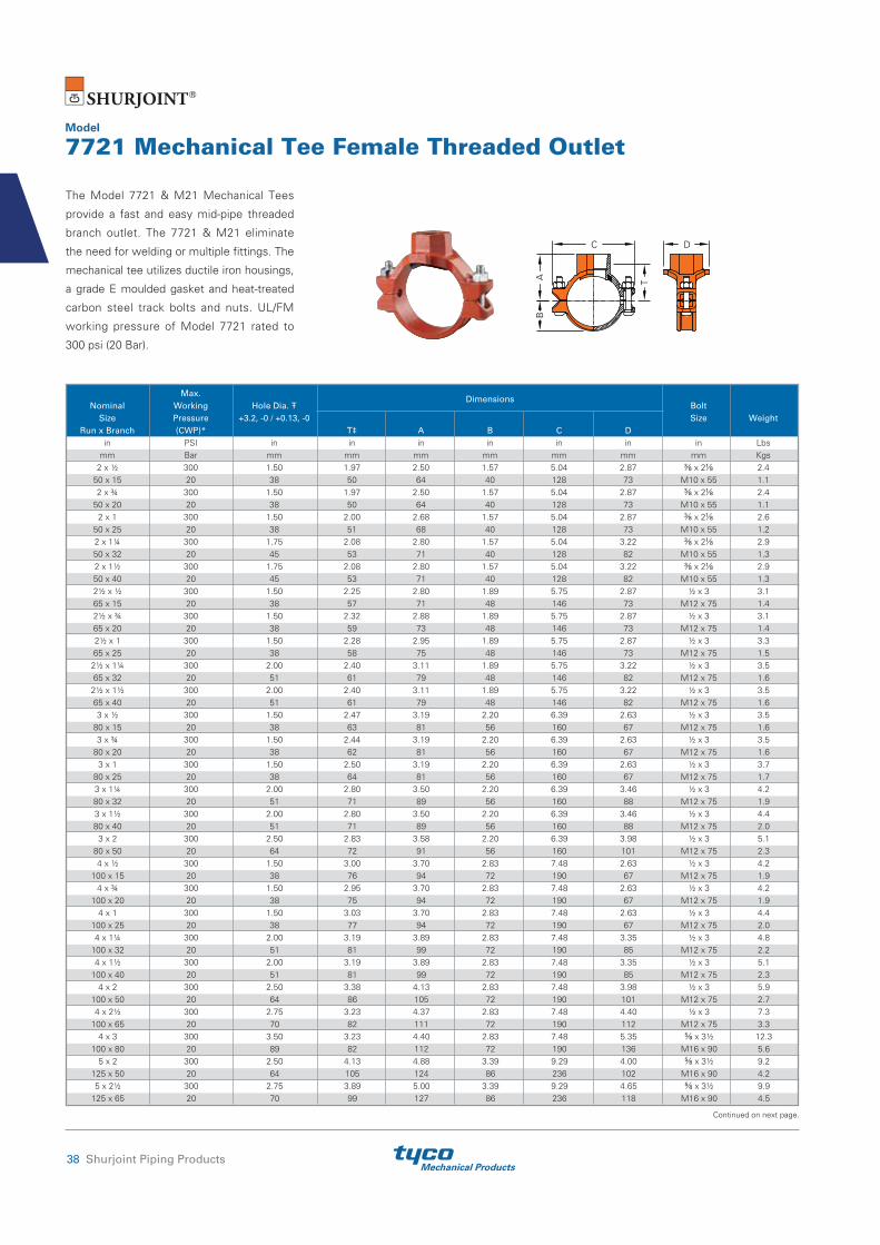
Mechanical Products38 Shurjoint Piping Products
Model
7721 Mechanical Tee Female Threaded Outlet
The Model 7721 & M21 Mechanical Tees
provide a fast and easy mid-pipe threaded
branch outlet. The 7721 & M21 eliminate
the need for welding or multiple fittings. The
mechanical tee utilizes ductile iron housings,
a grade E moulded gasket and heat-treated
carbon steel track bolts and nuts. UL/FM
working pressure of Model 7721 rated to
300 psi (20 Bar).
Max. Dimensions
Nominal Working Hole Dia. Bolt Size Pressure +3.2, -0 / +0.13, -0 Size Weight Run x Branch (CWP)* T‡ A B C D in PSI in in in in in in in Lbs mm Bar mm mm mm mm mm mm mm Kgs 2 x ½ 300 1.50 1.97 2.50 1.57 5.04 2.87 ⅜ x 2⅛ 2.4 50 x 15 20 38 50 64 40 128 73 M10 x 55 1.1 2 x ¾ 300 1.50 1.97 2.50 1.57 5.04 2.87 ⅜ x 2⅛ 2.4 50 x 20 20 38 50 64 40 128 73 M10 x 55 1.1 2 x 1 300 1.50 2.00 2.68 1.57 5.04 2.87 ⅜ x 2⅛ 2.6 50 x 25 20 38 51 68 40 128 73 M10 x 55 1.2 2 x 1¼ 300 1.75 2.08 2.80 1.57 5.04 3.22 ⅜ x 2⅛ 2.9 50 x 32 20 45 53 71 40 128 82 M10 x 55 1.3 2 x 1½ 300 1.75 2.08 2.80 1.57 5.04 3.22 ⅜ x 2⅛ 2.9 50 x 40 20 45 53 71 40 128 82 M10 x 55 1.3 2½ x ½ 300 1.50 2.25 2.80 1.89 5.75 2.87 ½ x 3 3.1 65 x 15 20 38 57 71 48 146 73 M12 x 75 1.4 2½ x ¾ 300 1.50 2.32 2.88 1.89 5.75 2.87 ½ x 3 3.1 65 x 20 20 38 59 73 48 146 73 M12 x 75 1.4 2½ x 1 300 1.50 2.28 2.95 1.89 5.75 2.87 ½ x 3 3.3 65 x 25 20 38 58 75 48 146 73 M12 x 75 1.5 2½ x 1¼ 300 2.00 2.40 3.11 1.89 5.75 3.22 ½ x 3 3.5 65 x 32 20 51 61 79 48 146 82 M12 x 75 1.6 2½ x 1½ 300 2.00 2.40 3.11 1.89 5.75 3.22 ½ x 3 3.5 65 x 40 20 51 61 79 48 146 82 M12 x 75 1.6 3 x ½ 300 1.50 2.47 3.19 2.20 6.39 2.63 ½ x 3 3.5 80 x 15 20 38 63 81 56 160 67 M12 x 75 1.6 3 x ¾ 300 1.50 2.44 3.19 2.20 6.39 2.63 ½ x 3 3.5 80 x 20 20 38 62 81 56 160 67 M12 x 75 1.6 3 x 1 300 1.50 2.50 3.19 2.20 6.39 2.63 ½ x 3 3.7 80 x 25 20 38 64 81 56 160 67 M12 x 75 1.7 3 x 1¼ 300 2.00 2.80 3.50 2.20 6.39 3.46 ½ x 3 4.2 80 x 32 20 51 71 89 56 160 88 M12 x 75 1.9 3 x 1½ 300 2.00 2.80 3.50 2.20 6.39 3.46 ½ x 3 4.4 80 x 40 20 51 71 89 56 160 88 M12 x 75 2.0 3 x 2 300 2.50 2.83 3.58 2.20 6.39 3.98 ½ x 3 5.1 80 x 50 20 64 72 91 56 160 101 M12 x 75 2.3 4 x ½ 300 1.50 3.00 3.70 2.83 7.48 2.63 ½ x 3 4.2 100 x 15 20 38 76 94 72 190 67 M12 x 75 1.9 4 x ¾ 300 1.50 2.95 3.70 2.83 7.48 2.63 ½ x 3 4.2 100 x 20 20 38 75 94 72 190 67 M12 x 75 1.9 4 x 1 300 1.50 3.03 3.70 2.83 7.48 2.63 ½ x 3 4.4 100 x 25 20 38 77 94 72 190 67 M12 x 75 2.0 4 x 1¼ 300 2.00 3.19 3.89 2.83 7.48 3.35 ½ x 3 4.8 100 x 32 20 51 81 99 72 190 85 M12 x 75 2.2 4 x 1½ 300 2.00 3.19 3.89 2.83 7.48 3.35 ½ x 3 5.1 100 x 40 20 51 81 99 72 190 85 M12 x 75 2.3 4 x 2 300 2.50 3.38 4.13 2.83 7.48 3.98 ½ x 3 5.9 100 x 50 20 64 86 105 72 190 101 M12 x 75 2.7 4 x 2½ 300 2.75 3.23 4.37 2.83 7.48 4.40 ½ x 3 7.3 100 x 65 20 70 82 111 72 190 112 M12 x 75 3.3 4 x 3 300 3.50 3.23 4.40 2.83 7.48 5.35 ⅝ x 3½ 12.3 100 x 80 20 89 82 112 72 190 136 M16 x 90 5.6 5 x 2 300 2.50 4.13 4.88 3.39 9.29 4.00 ⅝ x 3½ 9.2 125 x 50 20 64 105 124 86 236 102 M16 x 90 4.2 5 x 2½ 300 2.75 3.89 5.00 3.39 9.29 4.65 ⅝ x 3½ 9.9 125 x 65 20 70 99 127 86 236 118 M16 x 90 4.5
Continued on next page.
AB
T
C D

Mechanical ProductsShurjoint Piping Products 39
Max. Dimensions
Nominal Working Hole Dia. Bolt Size Pressure +3.2, -0 / +0.13, -0 Size Weight Run x Branch (CWP)* T‡ A B C D in PSI in in in in in in in Lbs mm Bar mm mm mm mm mm mm mm Kgs 6 x ½ 300 2.00 4.48 5.03 3.86 10.07 3.50 ⅝ x 55/16 9.7 150 x 15 20 51 114 128 98 256 89 M16 x 135 4.4 6 x 1 300 2.00 4.33 5.00 3.86 10.07 3.50 ⅝ x 55/16 9.7 150 x 25 20 51 110 127 98 256 89 M16 x 135 4.4 6 x 1¼ 300 2.00 4.29 5.00 3.86 10.07 3.66 ⅝ x 55/16 9.7 150 x 32 20 51 109 127 98 256 93 M16 x 135 4.4 6 x 1½ 300 2.00 4.29 5.00 3.86 10.07 3.66 ⅝ x 55/16 9.7 150 x 40 20 51 109 127 98 256 93 M16 x 135 4.4 6 x 2 300 2.50 4.45 5.29 3.86 10.07 3.98 ⅝ x 55/16 10.6 150 x 50 20 64 113 132 98 256 101 M16 x 135 4.8 6 x 2½ 300 2.75 4.37 5.50 3.86 10.07 4.65 ⅝ x 55/16 11.9 150 x 65 20 70 111 140 98 256 118 M16 x 135 5.4 6 x 3 300 3.50 4.33 5.50 3.86 10.07 5.39 ⅝ x 55/16 13.2 150 x 80 20 89 110 140 98 256 137 M16 x 135 6.0 6 x 4 300 4.50 4.21 5.50 3.86 10.07 6.46 ⅝ x 55/16 14.5 150 x 100 20 114 107 140 98 256 164 M16 x 135 6.6 8 x ½ 300 2.75 5.31 5.82 4.72 12.87 4.40 ¾ x 4¾ 12.5 200 x 15 20 70 135 148 120 327 112 M20 x 120 5.7 8 x 1 300 2.75 5.31 5.98 4.72 12.87 4.40 ¾ x 4¾ 12.5 200 x 25 20 70 135 152 120 327 112 M20 x 120 5.7 8 x 1¼ 300 2.75 5.31 5.98 4.72 12.87 3.98 ¾ x 4¾ 12.5 200 x 32 20 70 135 152 120 327 101 M20 x 120 5.7 8 x 1½ 300 2.75 5.31 5.98 4.72 12.87 3.98 ¾ x 4¾ 12.5 200 x 40 20 70 135 152 120 327 101 M20 x 120 5.7 8 x 2 300 2.75 5.31 6.54 4.72 12.87 3.98 ¾ x 4¾ 13.6 200 x 50 20 70 135 166 120 327 101 M20 x 120 6.2 8 x 2½ 300 2.75 5.39 6.54 4.72 12.87 4.09 ¾ x 4¾ 13.9 200 x 65 20 70 137 166 120 327 104 M20 x 120 6.3 8 x 3 300 3.50 5.35 6.54 4.72 12.87 5.04 ¾ x 4¾ 15.6 200 x 80 20 89 136 166 120 327 128 M20 x 120 7.1 8 x 4 300 4.50 5.24 6.54 4.72 12.87 6.46 ¾ x 4¾ 17.6 200 x 100 20 114 133 166 120 327 164 M20 x 120 8.0
Hole diameters listed are suggested hole diameters. ‡ T: Take-Out (Center of run to end of pipe to be engaged.)* Working pressure is based on standard wall carbon steel pipe.
Continued from previous page.

Mechanical Products40 Shurjoint Piping Products
Max. Dimensions
Nominal Pipe Working Hole Dia. Bolt Size O.D. Pressure +3.2, -0 / +0.13, -0 Size Weight Run x Branch (CWP)** T‡ A B C D in in PSI in in in in in in in Lbs mm mm Bar mm mm mm mm mm mm mm Kgs 2 x ½ 2.375 x 0.840 300 1.50 1.97 2.50 1.50 4.56 3.19 ⅜ x 2⅛ 2.18 50 x 15 60.3 x 21.3 20 38 50 63.5 38.1 115.9 81 M10 x 55 0.99 2 x ¾ 2.375 x 1.050 300 1.50 1.97 2.50 1.50 4.56 3.19 ⅜ x 2⅛ 2.22 50 x 20 60.3 x 26.7 20 38 50 63.5 38.1 115.9 81 M10 x 55 1.01 2 x 1 2.375 x 1.315 300 1.50 1.85 2.50 1.50 4.56 3.19 ⅜ x 2⅛ 2.40 50 x 25 60.3 x 33.4 20 38 47 63.5 38.1 115.9 81 M10 x 55 1.09 2 x 1¼ 2.375 x 1.660 300 [1.75] 2.05 2.87 1.50 4.56 3.31 ⅜ x 2⅛ 2.77 50 x 32 60.3 x 42.2 20 [45] 52 73.0 38.1 115.9 84 M10 x 55 1.26 2 x 1½ 2.375 x 1.900 300 [1.75] 2.08 3.00 1.50 4.56 3.31 ⅜ x 2⅛ 3.01 50 x 40 60.3 x 48.3 20 [45] 52 76.2 38.1 115.9 84 M10 x 55 1.37 2½ x ½ 2.875 x 0.840 300 1.50 2.20 2.75 1.75 5.56 3.19 ⅛ x 2⅜ 2.60 65 x 15 73.0 x 21.3 20 38 56 69.9 44.5 141.3 81 M12 x 60 1.20 2½ x ¾ 2.875 x 1.050 300 1.50 2.20 2.75 1.75 5.56 3.19 ⅛ x 2⅜ 2.70 65 x 20 73.0 x 26.7 20 38 56 69.9 44.5 141.3 81 M12 x 60 1.20 2½ x 1 2.875 x 1.315 300 1.50 2.09 2.75 1.75 5.56 3.19 ⅛ x 2⅜ 2.86 65 x 25 73.0 x 33.4 20 38 53 69.9 44.5 141.3 81 M12 x 60 1.30 2½ x 1¼ 2.875 x 1.660 300 2.00 2.28 3.00 1.75 5.56 3.70 ⅛ x 2⅜ 3.21 65 x 32 73.0 x 42.2 20 51 58 76.2 44.5 141.3 94 M12 x 60 1.46 2½ x 1½ 2.875 x 1.900 300 2.00 2.28 3.00 1.75 5.56 3.70 ⅛ x 2⅜ 3.43 65 x 40 73.0 x 48.3 20 51 58 76.2 44.5 141.3 94 M12 x 60 1.56
76.1 mm x 15 3.000 x 0.840 300 1.50 2.20 2.75 1.81 5.69 3.19 ⅛ x 2⅜ 2.64
76.1 x 21.3 20 38 56 69.9 46.1 144.5 81 M12 x 60 1.20
76.1 mm x 20 3.000 x 1.050 300 1.50 2.20 2.75 1.81 5.69 3.19 ⅛ x 2⅜ 2.64
76.1 x 26.7 20 38 56 69.9 46.1 144.5 81 M12 x 60 1.20
76.1 mm x 25 3.000 x 1.315 300 1.50 2.09 2.75 1.81 5.69 3.19 ⅛ x 2⅜ 2.86
76.1 x 33.4 20 38 53 69.9 46.1 144.5 81 M12 x 60 1.30
76.1 mm x 32 3.000 x 1.660 300 2.00 2.28 3.00 1.81 5.69 3.70 ⅛ x 2⅜ 3.21
76.1 x 42.2 20 51 58 76.2 46.1 144.5 94 M12 x 60 1.46
76.1 mm x 40 3.000 x 1.900 300 2.00 2.28 3.00 1.81 5.69 3.70 ⅛ x 2⅜ 3.43
76.1 x 48.3 20 51 58 76.2 46.1 144.5 94 M12 x 60 1.56 3 x ½ 3.500 x 0.840 300 1.50 2.36 3.06 2.09 6.19 3.19 ½ x 3 3.17 80 x 15 88.9 x 21.3 20 38 60 77.8 53.2 157.2 81 M12 x 75 1.44 3 x ¾ 3.500 x 1.050 300 1.50 2.32 3.06 2.09 6.19 3.19 ½ x 3 3.21 80 x 20 88.9 x 26.7 20 38 59 77.8 53.2 157.2 81 M12 x 75 1.46 3 x 1 3.500 x 1.315 300 1.50 2.40 3.06 2.09 6.19 3.19 ½ x 3 3.37 80 x 25 88.9 x 33.4 20 38 61 77.8 53.2 157.2 81 M12 x 75 1.53 3 x 1¼ 3.500 x 1.660 300 2.00 2.56 3.25 2.09 6.19 3.70 ½ x 3 3.98 80 x 32 88.9 x 42.2 20 51 65 82.6 53.2 157.2 94 M12 x 75 1.81 3 x 1½ 3.500 x 1.900 300 2.00 2.80 3.50 2.09 6.19 3.70 ½ x 3 4.14 80 x 40 88.9 x 48.3 20 51 71 88.9 53.2 157.2 94 M12 x 75 1.88 3 x 2 3.500 x 2.375 300 2.50 2.76 3.50 2.09 6.19 4.25 ½ x 3 4.55 80 x 50 88.9 x 60.3 20 64 70 88.9 53.2 157.2 108 M12 x 75 2.07 4 x ½ 3.500 x 0.840 300 1.50 2.83 3.69 2.63 7.19 3.13 ½ x 3 3.59 100 x 15 114.3 x 21.3 20 38 72 93.7 66.7 182.6 79.4 M12 x 75 1.63 4 x ¾ 4.500 x 1.050 300 1.50 2.79 3.69 2.63 7.19 3.13 ½ x 3 3.61 100 x 20 114.3 x 26.7 20 38 71 93.7 66.7 182.6 79.4 M12 x 75 1.64 4 x 1 4.500 x 1.315 300 1.50 2.87 3.69 2.63 7.19 3.13 ½ x 3 3.74 100 x 25 114.3 x 33.4 20 38 73 93.7 66.7 182.6 79.4 M12 x 75 1.70 4 x 1¼ 4.500 x 1.660 300 2.00 3.07 3.63 2.63 7.19 4.00 ½ x 3 4.18 100 x 32 114.3 x 42.2 20 51 78 92.1 66.7 182.6 101.6 M12 x 75 1.90 4 x 1½ 4.500 x 1.900 300 2.00 3.31 3.63 2.63 7.19 4.00 ½ x 3 4.49 100 x 40 114.3 x 48.3 20 51 84 92.1 66.7 182.6 101.6 M12 x 75 2.04
Model
M21 Mechanical Tee Female Threaded Outlet
Threads are NPT per ANSI B1.20.1 or BSPT
per ISO 7. UL/FM working pressure is
300 psi (20 Bar).
Continued on next page.
AB
T
C D

Mechanical ProductsShurjoint Piping Products 41
Max. Dimensions
Nominal Pipe Working Hole Dia. Bolt Size O.D. Pressure +3.2, -0 / +0.13, -0 Size Weight Run x Branch (CWP)** T‡ A B C D in in PSI in in in in in in in Lbs mm mm Bar mm mm mm mm mm mm mm Kgs 4 x 2 4.500 x 2.375 300 2.50 3.27 4.00 2.63 7.19 4.00 ½ x 3 5.00 100 x 50 114.3 x 60.3 20 64 83 101.6 66.7 182.6 101.6 M12 x 75 2.27 4 x 2½ 4.500 x 2.875 300 2.75 2.87 4.00 2.63 7.19 4.44 ½ x 3 5.43 100 x 65 114.3 x 73.0 20 70 73 101.6 66.7 182.6 112.7 M12 x 75 2.47 100 x 76.1 mm
4.500 x 3.000 300 2.75 2.87 4.00 2.63 7.19 4.44 ½ x 3 5.65 114.3 x 76.1 20 70 73 101.6 66.7 182.6 112.7 M12 x 75 2.57 4 x 3 4.500 x 3.500 300 3.50 3.31 4.13 2.63 7.19 5.06 ½ x 3 6.41 100 x 80 114.3 x 88.9 20 89 84 104.8 66.7 182.6 128.6 M12 x 75 2.91
139.7 mm x 50* 5.500 x 2.375 300 2.50 3.27 4.75 3.19 8.81 4.19 ⅝ x 3½ 6.38
139.7 x 60.3 20 64 83 120.7 81.0 223.8 106.4 M16 x 90 2.90 139.7 mm 5.500 x 3.000 300 2.75 3.67 4.75 3.19 8.81 4.57 ⅝ x 3½ 7.40 x 76.1 mm* 139.7 x 76.1 20 70 93 120.7 81.0 223.8 115.9 M16 x 90 3.40 139.7 mm x 80*
5.500 x 3.500 300 3.50 3.82 4.75 3.19 8.81 5.19 ⅝ x 3½ 8.41 139.7 x 88.9 20 89 97 127.0 81.0 223.8 131.8 M16 x 90 3.82 5 x 2 5.563 x 2.375 300 2.50 3.27 4.75 3.19 8.81 4.19 ⅝ x 3½ 6.38 125 x 50 141.3 x 60.3 20 64 83 120.7 81.0 223.8 106.4 M16 x 90 2.90 5 x 2½ 5.563 x 2.875 300 2.75 3.67 4.75 3.19 8.81 4.44 ⅝ x 3½ 7.46 125 x 65 141.3 x 73.0 20 70 93 120.7 81.0 223.8 112.7 M16 x 90 3.39 5 x 3 5.563 x 3.500 300 3.50 3.82 4.75 3.19 8.81 5.19 ⅝ x 3½ 8.40 125 x 80 141.3 x 88.9 20 89 97 127.0 81.0 223.8 131.8 M16 x 90 3.82 165.1 mm x 32
6.500 x 1.660 300 2.00 4.41 5.13 3.72 9.87 3.63 ⅝ x 3½ 5.57 165.1 x 42.2 20 51 112 130.2 94.5 250.8 92.1 M16 x 90 2.53 165.1 mm x 40
6.500 x 1.900 300 2.00 4.41 5.13 3.72 9.87 3.63 ⅝ x 3½ 6.60 165.1 x 48.3 20 51 112 130.2 94.5 250.8 92.1 M16 x 90 3.00 165.1 mm x 50
6.500 x 2.375 300 2.50 4.37 5.13 3.72 9.87 4.19 ⅝ x 3½ 6.97 165.1 x 60.3 20 64 111 130.2 94.5 250.8 106.4 M16 x 90 3.17 165.1 mm x 65
6.500 x 2.875 300 2.75 3.98 5.13 3.72 9.87 4.44 ⅝ x 3½ 7.88 165.1 x 73.0 20 70 101 130.2 94.5 250.8 112.7 M16 x 90 3.58 165.1 mm 6.500 x 2.875 300 2.75 3.98 5.13 3.72 9.87 4.56 ⅝ x 3½ 8.25 x 76.1 mm 165.1 x 76.1 20 70 101 130.2 94.5 250.8 115.9 M16 x 90 3.75 165.1 mm x 80
6.500 x 3.500 300 3.50 4.33 5.50 3.72 9.87 5.19 ⅝ x 3½ 9.09 165.1 x 88.9 20 89 110 139.7 94.5 250.8 131.8 M16 x 90 4.13 165.1 mm x 100
6.500 x 4.500 300 4.50 4.45 5.75 3.72 9.87 6.25 ⅝ x 3½ 10.50 165.1 x 114.3 20 114 113 146.1 94.5 250.8 158.8 M16 x 90 4.77 6 x 1¼ 6.625 x 1.660 300 2.00 4.41 5.13 3.72 9.87 3.63 ⅝ x 3½ 6.41 150 x 32 168.3 x 42.2 20 51 112 130.2 94.5 250.8 92.1 M16 x 90 2.91 6 x 1½ 6.625 x 1.900 300 2.00 4.41 5.13 3.72 9.87 3.63 ⅝ x 3½ 6.58 150 x 40 168.3 x 48.3 20 51 112 130.2 94.5 250.8 92.1 M16 x 90 2.99 6 x 2 6.625 x 2.375 300 2.50 4.37 5.13 3.72 9.87 4.19 ⅝ x 3½ 7.00 150 x 50 168.3 x 60.3 20 64 111 130.2 94.5 250.8 106.4 M16 x 90 3.18 6 x 2½ 6.625 x 2.875 300 2.75 3.98 5.13 3.72 9.87 4.44 ⅝ x 3½ 7.88 150 x 65 168.3 x 73.0 20 70 101 130.2 94.5 250.8 112.7 M16 x 90 3.58 150 x 76.1 mm
6.625 x 2.875 300 2.75 3.98 5.13 3.72 9.87 4.56 ⅝ x 3½ 9.02 168.3 x 76.1 20 70 101 130.2 94.5 250.8 115.9 M16 x 90 3.58 6 x 3 6.625 x 3.500 300 3.50 4.33 5.50 3.72 9.87 5.19 ⅝ x 3½ 9.02 150 x 80 168.3 x 88.9 20 89 110 139.7 94.5 250.8 131.8 M16 x 90 4.10 6 x 4 6.625 x 4.500 300 4.50 4.45 5.75 3.72 9.87 6.25 ⅝ x 3½ 10.47 150 x 100 168.3 x 114.3 20 114 113 146.1 94.5 250.8 158.8 M16 x 90 4.76
Hole diameters listed are suggested hole diameters. ‡ T: Take-Out (Center of run to end of pipe to be engaged.)[ ] Important: Make special note of the hole saw size and maximum diameter allowed on these sizes, deviation could lead to joint failure.* Non-standard/stock items may require longer lead time.**Working pressure is based on standard wall carbon steel pipe.
Continued from previous page.

Mechanical Products42 Shurjoint Piping Products
The Model 7722 Mechanical Tee provides
a fast and easy mid-pipe threaded branch
outlet. The mechanical tee utilizes ductile iron
housings, a grade E gasket and heat-treated
carbon steel track bolts and nuts. Housings
are painted orange or red, or as an option
can be supplied hot dipped zinc galvanized or
epoxy coated. Maximum working pressure:
300 psi (20 Bar). Gaskets are interchangeable
between Models 7721 & 7722.
Model
7722 Mechanical Tee Grooved-End Outlet
AB
C D
Continued on next page.
Max. Dimensions
Nominal Pipe Working Hole Dia. Bolt Size O.D. Pressure +0.13, -0 / +3.2, -0 Size Weight Run x Branch (CWP)** A B C D in in PSI in in in in in in Lbs mm mm Bar mm mm mm mm mm mm Kgs 2 x 1* 2.375 x 1.315 300 1.50 2.68 1.57 5.04 2.87 ⅜ x 2⅛ 2.2 50 x 25 60.3 x 33.4 20 38 68 40 128 73 M10 x 55 1.0 2 x 1¼ 2.375 x 1.660 300 1.75 2.80 1.57 5.04 3.22 ⅜ x 2⅛ 2.2 50 x 32 60.3 x 42.2 20 45 71 40 128 82 M10 x 55 1.0 2 x 1½ 2.375 x 1.900 300 1.75 2.80 1.57 5.04 3.22 ⅜ x 2⅛ 2.6 50 x 40 60.3 x 48.3 20 45 71 40 128 82 M10 x 55 1.2 2½ x 1* 2.875/3.000 x1.315 300 1.50 2.95 1.89 5.75 2.87 ½ x 3 4.0 65 x 25 73.0/76.1 x 33.4 20 38 75 48 146 73 M12 x 75 1.8 2½ x 1¼ 2.875/3.000 x 1.660 300 2.00 3.11 1.89 5.75 3.22 ½ x 3 3.7 65 x 32 73.0/76.1 x 42.2 20 51 79 48 146 82 M12 x 75 1.7 2½ x 1½ 2.875/3.000 x 1.900 300 2.00 3.11 1.89 5.75 3.22 ½ x 3 4.2 65 x 40 73.0/76.1 x 48.3 20 51 79 48 146 82 M12 x 75 1.9 3 x 1 3.500 x 1.315 300 1.50 3.30 2.20 6.30 2.91 ½ x 3 3.7 80 x 25 88.9 x 33.4 20 38 84 56 160 74 M12 x 75 1.7 3 x 1¼ 3.500 x 1.660 300 2.00 3.50 2.20 6.30 3.46 ½ x 3 4.0 80 x 32 88.9 x 42.2 20 51 89 56 160 88 M12 x 75 1.8 3 x 1½ 3.500 x 1.900 300 2.00 3.50 2.20 6.30 3.46 ½ x 3 4.2 80 x 40 88.9 x 48.3 20 51 89 56 160 88 M12 x 75 1.9 3 x 2 3.500 x 2.375 300 2.50 3.58 2.20 6.30 3.98 ½ x 3 4.8 80 x 50 88.9 x 60.3 20 64 91 56 160 101 M12 x 75 2.2 4 x 1 4.500 x 1.315 300 1.50 3.89 2.83 7.48 2.63 ½ x 3 4.4 100 x 25 114.3 x 33.4 20 38 94 72 190 67 M12 x 75 2.0 4 x 1¼ 4.500 x 1,660 300 2.00 3.89 2.83 7.48 3.35 ½ x 3 4.6 100 x 32 114.3 x 42.2 20 51 99 72 190 85 M12 x 75 2.1 4 x 1½ 4.500 x 1.900 300 2.00 3.89 2.83 7.48 3.35 ½ x 3 4.8 100 x 40 114.3 x 48.3 20 51 99 72 190 85 M12 x 75 2.2 4 x 2 4.500 x 2.375 300 2.50 4.13 2.83 7.48 3.98 ½ x 3 5.9 100 x 50 114.3 x 60.3 20 64 105 72 190 101 M12 x 75 2.7 4 x 2½ 4.500 x 2.875 300 2.75 4.37 2.83 7.48 4.40 ½ x 3 6.6 100 x 65 114.3 x 73.0 20 70 111 72 190 112 M12 x 75 3.0 4 x 2½ 4.500 x 3.000 300 2.75 4.37 2.83 7.48 4.40 ½ x 3 6.6 100 x 65 114.3 x 76.1 20 70 111 72 190 112 M12 x 75 3.0 4 x 3 4.500 x 3.500 300 3.50 4.40 2.83 7.48 5.35 ⅝ x 3½ 11.4 100 x 80 114.3 x 88.9 20 89 112 72 190 136 M16 x 90 5.2 5 x 2 5.500/5.563 x 2.375 300 2.50 4.88 3.39 9.29 4.00 ⅝ x 3½ 9.2 125 x 50 139.7/141.3 x 60.3 20 64 124 86 236 102 M16 x 90 4.2 5 x 2½ 5.563 x 2.875 300 2.75 5.00 3.39 9.29 4.65 ⅝ x 3½ 9.5 125 x 65 141.3 x 73.0 20 70 127 86 236 118 M16 x 90 4.2 5 x 2½ 5.500 x 3.000 300 2.75 5.00 3.39 9.29 4.65 ⅝ x 3½ 9.5 125 x 65 139.7 x 76.1 20 70 127 86 236 118 M16 x 90 4.3 6 x 1¼ 6.500/6.625 x 1.660 300 2.00 5.00 3.86 10.08 3.66 ⅝ x 55/16 9.2 150 x 32 165.1/168.3 x 42.2 20 51 127 98 256 93 M16 x 135 4.2 6 x 1½ 6.500/6.625 x 1.900 300 2.00 5.00 3.86 10.08 3.66 ⅝ x 55/16 9.5 150 x 40 165.1/168.3 x 48.3 20 51 127 98 256 93 M16 x 135 4.3 6 x 2 6.500/6.625 x 2.375 300 2.50 5.20 3.86 10.08 3.98 ⅝ x 55/16 10.6 150 x 50 165.1/168.3 x 60.3 20 64 132 98 256 101 M16 x 135 4.8 6 x 2½ 6.625 x 2.875 300 2.75 5.50 3.86 10.08 4.65 ⅝ x 55/16 12.1 150 x 65 168.3 x 73.0 20 70 140 98 256 118 M16 x 135 5.5 6 x 2½ 6.500 x 3.000 300 2.75 5.50 3.86 10.08 4.65 ⅝ x 55/16 12.1 150 x 65 165.1 x 76.1 20 70 140 98 256 118 M16 x 135 5.5 6 x 3 6.500/6.625 x 3.500 300 3.50 5.50 3.86 10.08 5.39 ⅝ x 55/16 12.3 150 x 80 165.1/168.3 x 88.9 20 89 140 98 256 137 M16 x 135 5.6

Mechanical ProductsShurjoint Piping Products 43
Hole diameters listed are suggested hole diameters. * Non-standard/stock items may require longer lead time.**Working pressure is based on roll- or cut-grooved standard wall carbon steel pipe.
Max. Dimensions
Nominal Pipe Working Hole Dia. Bolt Size O.D. Pressure +0.13, -0 / +3.2, -0 Size Weight Run x Branch (CWP)** A B C D in in PSI in in in in in in Lbs mm mm Bar mm mm mm mm mm mm Kgs 6 x 4 6.500/6.625 x 4.500 300 4.50 5.50 3.86 10.08 6.46 ⅝ x 55/16 15.4 150 x 100 165.1/168.3 x 114.3 20 114 140 98 256 164 M16 x 135 7.0 8 x 2 8.625 x 2.375 300 2.75 6.54 4.72 12.87 3.89 ¾ x 4¾ 12.8 200 x 50 219.1 x 60.3 20 70 166 120 327 104 M20 x 120 5.8 8 x 2½ 8.625 x 2.875 300 2.75 6.54 4.72 12.87 4.09 ¾ x 4¾ 13.2 200 x 65 219.1 x 73.0 20 70 166 120 327 104 M20 x 120 6.0 8 x 2½ 8.625 x 3.000 300 2.75 6.54 4.72 12.87 4.09 ¾ x 4¾ 13.2 200 x 65 219.1 x 76.1 20 70 166 120 327 104 M20 x 120 6.0 8 x 3 8.625 x 3.500 300 3.50 6.54 4.72 12.87 5.04 ¾ x 4¾ 15.8 200 x 80 219.1 x 88.9 20 89 166 120 327 128 M20 x 120 7.2 8 x 4 8.625 x 4.500 300 4.50 6.54 4.72 12.87 6.46 ¾ x 4¾ 16.5 200 x 100 219.1 x 114.3 20 114 166 120 327 164 M20 x 120 7.5
Continued from previous page.
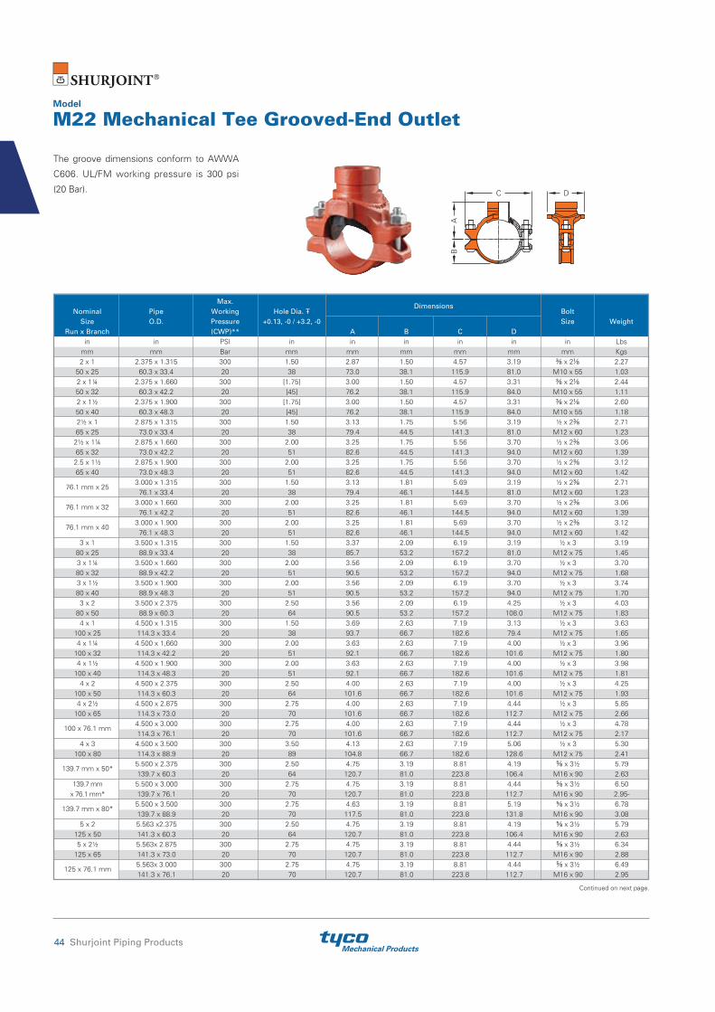
Mechanical Products44 Shurjoint Piping Products
Model
M22 Mechanical Tee Grooved-End Outlet
The groove dimensions conform to AWWA
C606. UL/FM working pressure is 300 psi
(20 Bar).
AB
C D
Continued on next page.
Max. Dimensions
Nominal Pipe Working Hole Dia. Bolt Size O.D. Pressure +0.13, -0 / +3.2, -0 Size Weight Run x Branch (CWP)** A B C D in in PSI in in in in in in Lbs mm mm Bar mm mm mm mm mm mm Kgs 2 x 1 2.375 x 1.315 300 1.50 2.87 1.50 4.57 3.19 ⅜ x 2⅛ 2.27 50 x 25 60.3 x 33.4 20 38 73.0 38.1 115.9 81.0 M10 x 55 1.03 2 x 1¼ 2.375 x 1.660 300 [1.75] 3.00 1.50 4.57 3.31 ⅜ x 2⅛ 2.44 50 x 32 60.3 x 42.2 20 [45] 76.2 38.1 115.9 84.0 M10 x 55 1.11 2 x 1½ 2.375 x 1.900 300 [1.75] 3.00 1.50 4.57 3.31 ⅜ x 2⅛ 2.60 50 x 40 60.3 x 48.3 20 [45] 76.2 38.1 115.9 84.0 M10 x 55 1.18 2½ x 1 2.875 x 1.315 300 1.50 3.13 1.75 5.56 3.19 ½ x 2⅜ 2.71 65 x 25 73.0 x 33.4 20 38 79.4 44.5 141.3 81.0 M12 x 60 1.23 2½ x 1¼ 2.875 x 1.660 300 2.00 3.25 1.75 5.56 3.70 ½ x 2⅜ 3.06 65 x 32 73.0 x 42.2 20 51 82.6 44.5 141.3 94.0 M12 x 60 1.39 2.5 x 1½ 2.875 x 1.900 300 2.00 3.25 1.75 5.56 3.70 ½ x 2⅜ 3.12 65 x 40 73.0 x 48.3 20 51 82.6 44.5 141.3 94.0 M12 x 60 1.42
76.1 mm x 25 3.000 x 1.315 300 1.50 3.13 1.81 5.69 3.19 ½ x 2⅜ 2.71
76.1 x 33.4 20 38 79.4 46.1 144.5 81.0 M12 x 60 1.23
76.1 mm x 32 3.000 x 1.660 300 2.00 3.25 1.81 5.69 3.70 ½ x 2⅜ 3.06
76.1 x 42.2 20 51 82.6 46.1 144.5 94.0 M12 x 60 1.39
76.1 mm x 40 3.000 x 1.900 300 2.00 3.25 1.81 5.69 3.70 ½ x 2⅜ 3.12
76.1 x 48.3 20 51 82.6 46.1 144.5 94.0 M12 x 60 1.42 3 x 1 3.500 x 1.315 300 1.50 3.37 2.09 6.19 3.19 ½ x 3 3.19 80 x 25 88.9 x 33.4 20 38 85.7 53.2 157.2 81.0 M12 x 75 1.45 3 x 1¼ 3.500 x 1.660 300 2.00 3.56 2.09 6.19 3.70 ½ x 3 3.70 80 x 32 88.9 x 42.2 20 51 90.5 53.2 157.2 94.0 M12 x 75 1.68 3 x 1½ 3.500 x 1.900 300 2.00 3.56 2.09 6.19 3.70 ½ x 3 3.74 80 x 40 88.9 x 48.3 20 51 90.5 53.2 157.2 94.0 M12 x 75 1.70 3 x 2 3.500 x 2.375 300 2.50 3.56 2.09 6.19 4.25 ½ x 3 4.03 80 x 50 88.9 x 60.3 20 64 90.5 53.2 157.2 108.0 M12 x 75 1.83 4 x 1 4.500 x 1.315 300 1.50 3.69 2.63 7.19 3.13 ½ x 3 3.63 100 x 25 114.3 x 33.4 20 38 93.7 66.7 182.6 79.4 M12 x 75 1.65 4 x 1¼ 4.500 x 1,660 300 2.00 3.63 2.63 7.19 4.00 ½ x 3 3.96 100 x 32 114.3 x 42.2 20 51 92.1 66.7 182.6 101.6 M12 x 75 1.80 4 x 1½ 4.500 x 1.900 300 2.00 3.63 2.63 7.19 4.00 ½ x 3 3.98 100 x 40 114.3 x 48.3 20 51 92.1 66.7 182.6 101.6 M12 x 75 1.81 4 x 2 4.500 x 2.375 300 2.50 4.00 2.63 7.19 4.00 ½ x 3 4.25 100 x 50 114.3 x 60.3 20 64 101.6 66.7 182.6 101.6 M12 x 75 1.93 4 x 2½ 4.500 x 2.875 300 2.75 4.00 2.63 7.19 4.44 ½ x 3 5.85 100 x 65 114.3 x 73.0 20 70 101.6 66.7 182.6 112.7 M12 x 75 2.66
100 x 76.1 mm 4.500 x 3.000 300 2.75 4.00 2.63 7.19 4.44 ½ x 3 4.78
114.3 x 76.1 20 70 101.6 66.7 182.6 112.7 M12 x 75 2.17 4 x 3 4.500 x 3.500 300 3.50 4.13 2.63 7.19 5.06 ½ x 3 5.30 100 x 80 114.3 x 88.9 20 89 104.8 66.7 182.6 128.6 M12 x 75 2.41
139.7 mm x 50* 5.500 x 2.375 300 2.50 4.75 3.19 8.81 4.19 ⅝ x 3½ 5.79
139.7 x 60.3 20 64 120.7 81.0 223.8 106.4 M16 x 90 2.63
139.7 mm 5.500 x 3.000 300 2.75 4.75 3.19 8.81 4.44 ⅝ x 3½ 6.50
x 76.1 mm* 139.7 x 76.1 20 70 120.7 81.0 223.8 112.7 M16 x 90 2.95-
139.7 mm x 80* 5.500 x 3.500 300 2.75 4.63 3.19 8.81 5.19 ⅝ x 3½ 6.78
139.7 x 88.9 20 70 117.5 81.0 223.8 131.8 M16 x 90 3.08 5 x 2 5.563 x2.375 300 2.50 4.75 3.19 8.81 4.19 ⅝ x 3½ 5.79 125 x 50 141.3 x 60.3 20 64 120.7 81.0 223.8 106.4 M16 x 90 2.63 5 x 2½ 5.563x 2.875 300 2.75 4.75 3.19 8.81 4.44 ⅝ x 3½ 6.34 125 x 65 141.3 x 73.0 20 70 120.7 81.0 223.8 112.7 M16 x 90 2.88
125 x 76.1 mm 5.563x 3.000 300 2.75 4.75 3.19 8.81 4.44 ⅝ x 3½ 6.49
141.3 x 76.1 20 70 120.7 81.0 223.8 112.7 M16 x 90 2.95

Mechanical ProductsShurjoint Piping Products 45
Hole diameters listed are suggested hole diameters. [ ] Important: Make special note of the hole saw size and maximum diameter allowed on these sizes, deviation could lead to joint failure.* Non-standard/stock items may require longer lead time.**Working pressure is based on grooved standard wall carbon steel pipe.
Max. Dimensions
Nominal Pipe Working Hole Dia. Bolt Size O.D. Pressure +0.13, -0 / +3.2, -0 Size Weight Run x Branch (CWP)** A B C D in in PSI in in in in in in Lbs mm mm Bar mm mm mm mm mm mm Kgs 5 x 3 5.563 x 3.500 300 2.75 4.63 3.19 8.81 5.19 ⅝ x 3½ 6.78 125 x 80 141.3 x 88.9 20 70 117.5 81.0 223.8 131.8 M16 x 90 3.08
165.1 mm x 32 6.500 x 1.660 300 2.00 5.13 3.72 9.87 3.63 ⅝ x 3½ 6.03
165.1 x 42.2 20 51 130.2 94.5 250.8 92.1 M16 x 90 2.74
165.1 mm x 40 6.500 x 1.900 300 2.00 5.13 3.72 9.87 3.63 ⅝ x 3½ 6.12
165.1 x 48.3 20 51 130.2 94.5 250.8 92.1 M16 x 90 2.78
165.1 mm x 50 6.500 x 2.375 300 2.50 5.13 3.72 9.87 4.19 ⅝ x 3½ 6.40
165.1 x 60.3 20 64 130.2 94.5 250.8 106.4 M16 x 90 2.91 6 x 2½ 6.625 x 2.875 300 2.75 5.13 3.72 9.87 4.44 ⅝ x 3½ 7.08 150 x 65 168.3 x 73.0 20 70 130.2 94.5 250.8 112.7 M16 x 90 3.22 165.1 mm
6.500 x 3.000 300 2.75 5.13 3.72 9.87 4.56 ⅝ x 3½ 7.44
x 76.1 mm 165.1 x 76.1 20 70 130.2 94.5 250.8 115.9 M16 x 90 3.38
165.1 mm x 80 6.500 x 3.500 300 3.50 5.13 3.72 9.87 5.19 ⅝ x 3½ 8.01
165.1 x 88.9 20 89 130.2 94.5 250.8 131.8 M16 x 90 3.64
165.1 mm x 100 6.500 x 4.500 300 4.50 5.40 3.72 9.87 6.25 ⅝ x 3½ 8.91
165.1 x 114.3 20 114 137.1 94.5 250.8 158.8 M16 x 90 4.05 6 x 1¼ 6.625 x 1.660 300 2.00 5.13 3.72 9.87 3.63 ⅝ x 3½ 6.05 150 x 32 168.3 x 42.2 20 51 130.2 94.5 250.8 92.1 M16 x 90 2.75 6 x 1½ 6.625 x 1.900 300 2.00 5.13 3.72 9.87 3.63 ⅝ x 3½ 6.12 150 x 40 168.3 x 48.3 20 51 130.2 94.5 250.8 92.1 M16 x 90 2.78 6 x 2 6.625 x 2.375 300 2.50 5.13 3.72 9.87 4.19 ⅝ x 3½ 6.42 150 x 50 168.3 x 60.3 20 64 130.2 94.5 250.8 106.4 M16 x 90 2.92 6 x 2½ 6.625 x 2.875 300 2.75 5.13 3.72 9.87 4.44 ⅝ x 3½ 7.08 150 x 65 168.3 x 73.0 20 70 130.2 94.5 250.8 112.7 M16 x 90 3.22 6 x 3 6.625 x 3.500 300 3.50 5.13 3.72 9.87 5.19 ⅝ x 3½ 8.10 150 x 80 168.3 x 88.9 20 89 130.2 94.5 250.8 131.8 M16 x 90 3.68 6 x 4 6.625 x 4.500 300 4.50 5.40 3.72 9.87 6.25 ⅝ x 3½ 8.91 150 x 100 168.3 x 114.3 20 114 137.1 94.5 250.8 158.8 M16 x 90 4.05
Continued from previous page.

Mechanical Products46 Shurjoint Piping Products
Hole Dimensions Surface Saddle- Let Hole Saw Max dia. Preparation Branch Size Size Allowed “A” in in in in mm mm mm mm ½, ¾, 1 13/16 1¼ 3½ 15, 20, 25 30 32 89
Hole Sizes for 723 Saddle-let
A
⅝" ( 16 mm )
Hole CuttingThe method of pipe preparation
requires the cutting or drilling of a specified
hole size on the centerline of the pipe.
Always use the correct hole saw size as
shown in the table and never use a torch
for cutting a hole. After the hole has been
cut all rough edges must be removed and
the area within ⅝” (16 mm) of the hole
should be inspected to ensure a clean
smooth surface, free of any indentations or
projections that could affect proper gasket
sealing.
The Model 723 Saddle-Let is the ideal outlet
fitting for making direct connections to
sprinkler heads, drop nipples and or gauges.
No need for welding, just cut or drill a hole
at the desired outlet location.
Model
723 Saddle-Let
Max. Dimensions
Nominal Working Hole Dia. Take-Out, Bolt Bolt Size Pressure +3.2, -0 / +0.13, -0 T Size Torque Weight Run x Branch (CWP) A B C D in PSI in in in in in
in Lbs-Ft Lbs
mm Bar mm mm mm mm mm Nm Kgs 1¼ x ½ 300 1.18 1.97 3.50 2.20 1.73 ⅜Ø 15-22 0.9 32 x 15 20 30 50.0 89.0 56.0 44.0 U-Bolt 20-30 0.4 1¼ x ¾ 300 1.18 1.97 3.50 2.20 1.73 ⅜Ø 15-22 0.9 32 x 20 20 30 50.0 89.0 56.0 44.0 U-Bolt 20-30 0.4 1¼ x 1 300 1.18 2.13 3.50 2.20 1.85 ⅜Ø 15-22 0.9 32 x 25 20 30 54.0 89.0 56.0 47.0 U-Bolt 20-30 0.4 1½ x ½ 300 1.18 2.09 3.50 2.24 1.81 ⅜Ø 15-22 0.9 40 x 15 20 30 53.0 89.0 57.0 46.0 U-Bolt 20-30 0.4 1½ x ¾ 300 1.18 2.09 3.50 2.24 1.81 ⅜Ø 15-22 0.9 40 x 20 20 30 53.0 89.0 57.0 46.0 U-Bolt 20-30 0.4 1½ x 1 300 1.18 2.28 3.50 2.24 1.93 ⅜Ø 15-22 0.9 40 x 25 20 30 58.0 89.0 57.0 49.0 U-Bolt 20-30 0.4 2 x ½ 300 1.18 2.36 3.82 2.24 2.09 ⅜Ø 15-22 0.9 50 x 15 20 30 60.0 97.0 57.0 53.0 U-Bolt 20-30 0.4 2 x ¾ 300 1.18 2.36 3.82 2.24 2.09 ⅜Ø 15-22 0.9 50 x 20 20 30 60.0 97.0 57.0 53.0 U-Bolt 20-30 0.4 2 x 1 300 1.18 2.52 3.82 2.24 2.20 ⅜Ø 15-22 0.9 50 x 25 20 30 64.0 97.0 57.0 56.0 U-Bolt 20-30 0.4 2½ x ½ 300 1.18 2.60 4.37 2.24 2.28 ⅜Ø 15-22 0.9 65 x 15 20 30 66.0 111.0 57.0 58.0 U-Bolt 20-30 0.4 2½ x ¾ 300 1.18 2.60 4.37 2.24 2.28 ⅜Ø 15-22 0.9 65 x 20 20 30 66.0 111.0 57.0 58.0 U-Bolt 20-30 0.4 2½ x 1 300 1.18 2.76 4.37 2.24 2.40 ⅜Ø 15-22 1.1 65 x 25 20 30 70.0 111.0 57.0 61.0 U-Bolt 20-30 0.5
Hole diameters listed are suggested hole saw diameters. T: Take-out (Center of run to end of pipe to be engaged)
* Working Pressure is based on standard wall carbon steel pipe.
T
BC
A

Mechanical ProductsShurjoint Piping Products 47
Pressure Performance DataDuctile Iron Couplings on Carbon Steel & Stainless Steel Pipe
The following tables show maximum working pressures (CWP)
of Shurjoint ductile iron couplings and flange adapters used on
both carbon steel and stainless steel pipes. Shurjoint ductile iron
couplings can be used in conjunction with stainless steel pipe in non-
corrosive environment as the flow media does not come in direct
contact with the coupling housings but rather only the gasket.
Nom. Cut-Grooved Roll-Grooved Size XS STD STD Sch. 10 Sch. 7 in psi psi psi psi psi mm Bar Bar Bar Bar Bar 1¼ 600 600 500 400 250 32 42 42 35 28 17 1½ 600 600 500 400 250 40 42 42 35 28 17 2 600 600 500 400 250 50 42 42 35 28 17 2½ 600 600 500 400 250 65 42 42 35 28 17 3 600 600 500 400 250 80 42 42 35 28 17 4 600 600 500 400 200 100 42 42 35 28 14 5 450 450 350 300 175 125 31 31 24 20 12 6 450 450 350 300 175 150 31 31 24 20 12 8 450 450 350 300 150 200 31 31 24 20 10
Nom. Cut-Grooved Roll-Grooved Size XS STD STD Sch. 10 Sch. 7 in psi psi psi psi psi mm Bar Bar Bar Bar Bar 1¼ 600 600 500 400 300 32 42 42 35 28 20 1½ 600 600 500 400 300 40 42 42 35 28 20 2 600 600 500 400 300 50 42 42 35 28 20 2½ 600 600 500 400 300 65 42 42 35 28 20 3 600 600 500 400 300 80 42 42 35 28 20 4 600 600 500 400 300 100 42 42 35 28 20 5 450 450 450 350 250 125 31 31 31 24 17 6 450 450 450 350 250 150 31 31 31 24 17 8 450 450 300 250 200 200 31 31 20 17 14 8 (K-9H) 450 450 300 250 200 200 31 31 20 17 14
Nom. Cut-Grooved Roll-Grooved Size Sch. 80S Sch. 40S Sch. 40S Sch. 10S Sch. 5S in psi psi psi psi psi mm Bar Bar Bar Bar Bar 1¼ 600 600 450 300 250 32 42 42 31 20 17 1½ 600 600 450 300 250 40 42 42 31 20 17 2 600 600 450 300 250 50 42 42 31 20 17 2½ 600 600 450 300 250 65 42 42 31 20 17 3 600 600 450 300 250 80 42 42 31 20 17 4 600 600 450 300 200 100 42 42 31 20 14 5 450 450 300 200
NR 125 31 31 20 14 6 450 450 300 125
NR 150 31 31 20 9 8 450 450 300 100
NR 200 31 31 20 7 8 (K-9H) 450 450 300 100
NR 200 31 31 20 7
Nom. Cut-Grooved Roll-Grooved Size Sch. 80S Sch. 40S Sch. 40S Sch. 10S Sch. 5S in psi psi psi psi psi mm Bar Bar Bar Bar Bar 1¼ 600 600 450 300 250 32 42 42 31 20 17 1½ 600 600 450 300 250 40 42 42 31 20 17 2 600 600 450 300 250 50 42 42 31 20 17 2½ 600 600 450 300 250 65 42 42 31 20 17 3 600 600 450 300 250 80 42 42 31 20 17 4 600 600 450 300 200 100 42 42 31 20 14 5 450 450 300 200
NR 125 31 31 20 14 6 450 450 300 125
NR 150 31 31 20 9 8 450 450 300 100
NR 200 31 31 20 7
Model Z05 on Carbon Steel Pipe
Model K-9 on Carbon Steel Pipe Model K-9 on Stainless Steel Pipe
Model Z05 on Stainless Steel Pipe

Mechanical Products48 Shurjoint Piping Products
Nom. Cut-Grooved Roll-Grooved Size XS STD STD Sch. 10 Sch. 7 in psi psi psi psi psi mm Bar Bar Bar Bar Bar 1¼ 750 750 750 600 400 32 52 52 52 42 28 1½ 750 750 750 600 400 40 52 52 52 42 28 2 750 750 750 600 400 50 52 52 52 42 28 2½ 750 750 750 600 400 65 52 52 52 42 28 3 750 750 750 600 400 80 52 52 52 42 28 4 750 750 750 600 400 100 52 52 52 42 28 5 750 750 750 500 350 125 52 52 52 35 24 6 700 700 700 400 300 150 48 48 48 28 20 8 600 600 600 350 250 200 42 42 42 24 17 10 500 500 500 300 200 250 35 35 35 20 14 12 400 400 400 250 150 300 28 28 28 17 10
Nom. Cut-Grooved Roll-Grooved Size Sch. 80S Sch. 40S Sch. 40S Sch. 10S Sch. 5S in psi psi psi psi psi mm Bar Bar Bar Bar Bar 1¼ 750 750 700 500 300 32 52 52 48 35 20 1½ 750 750 700 500 300 40 52 52 48 35 20 2 750 750 700 500 300 50 52 52 48 35 20 2½ 750 750 700 500 300 65 52 52 48 35 20 3 750 750 700 500 300 80 52 52 48 35 20 4 750 750 700 400 250 100 52 52 48 28 17 5 750 750 600 300
NR 125 52 52 42 20 6 700 700 500 200
NR 150 48 48 35 14 8 600 600 400 150
NR 200 42 42 28 10 10 500 500 300 100
NR 250 35 35 20 7 12 400 400 250 100
NR 300 28 28 17 7
Model Z07 on Carbon Steel Pipe Model Z07 on Stainless Steel Pipe
Nom. Cut-Grooved Roll-Grooved Size XS STD STD Sch. 10 Sch. 7 in psi psi psi psi psi mm Bar Bar Bar Bar Bar 1½ 750 750 750 600 400 40 52 52 52 42 28 2 750 750 750 600 400 50 52 52 52 42 28 2½ 750 750 750 600 400 65 52 52 52 42 28 3 750 750 750 600 400 80 52 52 52 42 28 4 750 750 750 600 400 100 52 52 52 42 28 5 750 750 750 500 350 125 52 52 52 35 24 6 700 700 700 400 300 150 48 48 48 28 20 8 600 600 600 350 250 200 42 42 42 24 17 10 500 500 500 300 200 250 35 35 35 20 14 12 400 400 400 250 150 300 28 28 28 17 10
Nom. Cut-Grooved Roll-Grooved Size Sch. 80S Sch. 40S Sch. 40S Sch. 10S Sch. 5S in psi psi psi psi psi mm Bar Bar Bar Bar Bar 1½ 750 750 700 500 300 40 52 52 48 35 20 2 750 750 700 500 300 50 52 52 48 35 20 2½ 750 750 700 500 300 65 52 52 48 35 20 3 750 750 700 500 300 80 52 52 48 35 20 4 750 750 700 400 250 100 52 52 48 28 17 5 750 750 600 300
NR 125 52 52 42 20 6 700 700 500 200
NR 150 48 48 35 14 8 600 600 400 150
NR 200 42 42 28 10 10 500 500 300 100
NR 250 35 35 20 7 12 400 400 250 100
NR 300 28 28 17 7
Model 7771 on Carbon Steel Pipe Model 7771 on Stainless Steel Pipe
Nom. Cut-Grooved Roll-Grooved Size XS STD STD Sch. 10 Sch. 7 in psi psi psi psi psi mm Bar Bar Bar Bar Bar 2 1000 1000 1000 750
NR 50 69 69 69 52 2½ 1000 1000 1000 600
NR 65 69 69 69 42 3 1000 1000 1000 600
NR 80 69 69 69 42 4 1000 1000 1000 600
NR 100 69 69 69 42 6 1000 1000 1000 450
NR 150 69 69 69 31 8 800 800 800 300
NR 200 55 55 55 20 10 800 800 800 300
NR 250 55 55 55 20 12 800 800 800 200
NR 300 55 55 55 14
Nom. Cut-Grooved Roll-Grooved Size Sch. 80S Sch. 40S Sch. 40S Sch. 10S Sch. 5S in psi psi psi psi psi mm Bar Bar Bar Bar Bar 2 1000 1000 750 500
NR 50 69 69 52 35 2½ 1000 1000 750 500
NR 65 69 69 52 35 3 1000 1000 750 500
NR 80 69 69 52 35 4 1000 1000 750 400
NR 100 69 69 52 28 6 1000 1000 500 200
NR 150 69 69 35 14 8 800 800 400 125
NR 200 55 55 28 9 10 800 800 400 125
NR 250 55 55 28 9 12 800 800 400 125
NR 300 55 55 28 9
Model XH-1000 on Carbon Steel Pipe Model XH-1000 on Stainless Steel Pipe

Mechanical ProductsShurjoint Piping Products 49
Nom. Cut-Grooved Roll-Grooved Size XS STD STD Sch. 10 Sch. 7 in psi psi psi psi psi mm Bar Bar Bar Bar Bar 1½ 300 300 300 300
NR 40 20 20 20 20 2 300 300 300 300
NR 50 20 20 20 20 2½ 300 300 300 300
NR 65 20 20 20 20 3 300 300 300 300
NR 80 20 20 20 20 4 300 300 300 300
NR 100 20 20 20 20 5 300 300 300 300
NR 125 20 20 20 20 6 300 300 300 300
NR 150 20 20 20 20 8 300 300 300 250
NR 200 20 20 20 17 10 300 300 300 250
NR 250 20 20 20 17
Nom. Cut-Grooved Roll-Grooved Size Sch. 80S Sch. 40S Sch. 40S Sch. 10S Sch. 5S in psi psi psi psi psi mm Bar Bar Bar Bar Bar 1½ 300 300 300 300
NR 40 20 20 20 20 2 300 300 300 300
NR 50 20 20 20 20 2½ 300 300 300 300
NR 65 20 20 20 20 3 300 300 300 300
NR 80 20 20 20 20 4 300 300 300 175
NR 100 20 20 20 12 5 300 300 250 150
NR 125 20 20 17 10 6 300 300 250 150
NR 150 20 20 17 10 8 300 300 200
NR
NR 200 20 20 14 10 300 300 200
NR
NR 250 20 20 14
Model G28 on Carbon Steel Pipe Model G28 on Stainless Steel Pipe
Nom. Cut-Grooved Roll-Grooved Size Sch. 80S Sch. 40S Sch. 40S Sch. 10S Sch. 5S in psi psi psi psi psi mm Bar Bar Bar Bar Bar 1 600 600 450 300 250 25 42 42 31 20 17 1¼ 600 600 450 300 250 32 42 42 31 20 17 1½ 600 600 450 300 250 40 42 42 31 20 17 2 600 600 450 300 250 50 42 42 31 20 17 2½ 600 600 450 300 250 65 42 42 31 20 17 3 600 600 450 300 250 80 42 42 31 20 17 4 600 600 450 300 200 100 42 42 31 20 14 5 450 450 300 200
NR 125 31 31 20 14 6 450 450 300 125
NR 150 31 31 20 9 8 450 450 300 100
NR 200 31 31 20 7 10 350 350 200
NR
NR 250 24 24 14 12 350 350 200
NR
NR 300 24 24 14
Nom. Cut-Grooved Roll-Grooved Size XS STD STD Sch. 10 Sch. 7 in psi psi psi psi psi mm Bar Bar Bar Bar Bar 1 600 600 500 400 300 25 42 42 35 28 20 1¼ 600 600 500 400 300 32 42 42 35 28 20 1½ 600 600 500 400 300 40 42 42 35 28 20 2 600 600 500 400 300 50 42 42 35 28 20 2½ 600 600 500 400 300 65 42 42 35 28 20 3 600 600 500 400 300 80 42 42 35 28 20 4 600 600 500 400 300 100 42 42 35 28 20 5 450 450 450 350 250 125 31 31 31 24 17 6 450 450 450 350 250 150 31 31 31 24 17 8 450 450 300 250 200 200 31 31 20 17 14 10 350 350 300 200 175 250 24 24 20 14 12 12 350 350 300 200 175 300 24 24 20 14 12
Model 7705 on Stainless Steel PipeModel 7705 on Carbon Steel Pipe
Nom. Cut-Grooved Roll-Grooved Size XS STD STD Sch. 10 Sch. 7 in psi psi psi psi psi mm Bar Bar Bar Bar Bar ¾ 1000 1000 1000* / 750 750* / 600 500 20 69 69 69* / 52 52* / 42 35 1 1000 1000 1000* / 750 750* / 600 500 25 69 69 69* / 52 52* / 42 35 1¼ 1000 1000 1000* / 750 750* / 600 500 32 69 69 69* / 52 52* / 42 35 1½ 1000 1000 1000* / 750 750* / 600 500 40 69 69 69* / 52 52* / 42 35 2 1000 1000 1000* / 750 750* / 600 500 50 69 69 69* / 52 52* / 42 35 2½ 1000 1000 1000* / 750 600 500 65 69 69 69* / 52 42 35 3 1000 1000 1000* / 750 600 500 80 69 69 69* / 52 42 35 4 1000 1000 1000* / 750 600 400 100 69 69 69* / 52 42 28 5 1000 1000 1000* / 750 500 350 125 69 69 69* / 52 35 24 6 1000 1000 1000* / 700 450 300 150 69 69 69* / 48 31 20 8 800 800 800* / 600 350 250 200 55 55 55* / 42 24 17 10 800 800 800* / 550 300 200 250 55 55 55* / 38 20 14 12 800 800 800* / 500 300 200 300 55 55 55* / 35 20 14
Nom. Cut-Grooved Roll-Grooved Size Sch. 80S Sch. 40S Sch. 40S Sch. 10S Sch. 5S in psi psi psi psi psi mm Bar Bar Bar Bar Bar ¾ 750 750 700 450 325 20 52 52 48 31 22 1 750 750 700 450 325 25 52 52 48 31 22 1¼ 750 750 700 450 325 32 52 52 48 31 22 1½ 750 750 700 450 325 40 52 52 48 31 22 2 750 750 700 450 325 50 52 52 48 31 22 2½ 750 750 700 450 325 65 52 52 48 31 22 3 750 750 700 450 325 80 52 52 48 31 22 4 750 750 700 400 250 100 52 52 48 28 17 5 750 750 600 300
NR 125 52 52 42 20 6 750 750 500 200
NR 150 52 52 35 14 8 600 600 450 150
NR 200 42 42 31 10 10 600 600 400 125
NR 250 42 42 28 9 12 600 600 400 125
NR 300 42 42 28 9
Model 7707 on Carbon Steel Pipe Model 7707 on Stainless Steel Pipe
Note: * Maximum line pressure, including surge, to which a joint should be subjected.

Mechanical Products50 Shurjoint Piping Products
* = all branch sizes, threaded and grooved * = all branch sizes, threaded and grooved
Hydrostatic shell test: 1125 psi (77 Bar) per ANSI B16.5
Nom. Cut-Grooved Roll-Grooved Size Sch. 80S Sch. 40S Sch. 40S Sch. 10S Sch. 5S in psi psi psi psi psi mm Bar Bar Bar Bar Bar 1½ x 1¼ 500 500 350 300 250 40 x 32 35 35 24 20 17 2 x 1½ 500 500 350 300 250 50 x 40 35 35 24 20 17 2½ x 2 500 500 350 300 250 65 x 50 35 35 24 20 17 3 x 2 500 500 350 300 250 80 x 50 35 35 24 20 17 3 x 2½ 500 500 350 300 250 80 x 65 35 35 24 20 17 4 x 2 500 500 350 300 250 100 x 50 35 35 24 20 17 4 x 2½ 500 500 350 300 200 100 x 65 35 35 24 20 14 4 x 3 500 500 300 250 200 100 x 80 35 35 20 17 14 5 x 4 400 400 300 250
NR 125 x 100 28 28 20 17 6 x 3 400 400 300 200
NR 150 x 80 28 28 20 14 6 x 4 400 400 300 175
NR 150 x 100 28 28 20 12 8 x 6 400 400 300 175
NR 200 x 150 28 28 20 12
Nom. Cut-Grooved Roll-Grooved Size XS STD STD Sch. 10 Sch. 7 in psi psi psi psi psi mm Bar Bar Bar Bar Bar 1½ x 1¼ 500 500 500 350 300 40 x 32 35 35 35 24 20 2 x 1½ 500 500 500 350 300 50 x 40 35 35 35 24 20 2½ x 2 500 500 500 350 300 65 x 50 35 35 35 24 20 3 x 2 500 500 500 350 300 80 x 50 35 35 35 24 20 3 x 2½ 500 500 500 350 300 80 x 65 35 35 35 24 20 4 x 2 500 500 500 350 300 100 x 50 35 35 35 24 20 4 x 2½ 500 500 500 350 300 100 x 65 35 35 35 24 20 4 x 3 500 500 500 300 250 100 x 80 35 35 35 20 17 5 x 4 400 400 400 300 250 125 x 100 28 28 28 20 17 6 x 3 400 400 400 300 200 150 x 80 28 28 28 20 14 6 x 4 400 400 400 300 175 150 x 100 28 28 28 20 12 8 x 6 400 400 400 300 175 200 x 150 28 28 28 20 12
Model 7706 on Stainless Steel PipeModel 7706 on Carbon Steel Pipe
Nom. Cut-Grooved Roll-Grooved Size XS STD STD Sch. 10 Sch. 7 in psi psi psi psi psi mm Bar Bar Bar Bar Bar 1½ x * 500 500 500 350 300 40 x * 35 35 35 24 20 2 x * 500 500 500 350 300 50 x * 35 35 35 24 20 2½ x * 500 500 500 350 300 65 x * 35 35 35 24 20 3 x * 500 500 500 350 300 80 x * 35 35 35 24 20 4 x * 500 500 500 350 300 100 x * 35 35 35 24 20 6 x * 400 400 400 350 300 150 x * 28 28 28 24 20
Nom. Cut-Grooved Roll-Grooved Size Sch. 80S Sch. 40S Sch. 40S Sch. 10S Sch. 5S in psi psi psi psi psi mm Bar Bar Bar Bar Bar 1½ x * 500 500 350 300 250 40 x * 35 35 24 20 17 2 x * 500 500 350 300 250 50 x * 35 35 24 20 17 2½ x * 500 500 350 300 250 65 x * 35 35 24 20 17 3 x * 500 500 350 300 250 80 x * 35 35 24 20 17 4 x * 500 500 350 300 250 100 x * 35 35 24 20 17 6 x * 400 400 300 300 250 150 x * 28 28 20 20 17
Model C-7 on Carbon Steel Pipe Model C-7 on Stainless Steel Pipe
Nom. Cut-Grooved Roll-Grooved Size XS STD STD Sch. 10 Sch. 7 in psi psi psi psi psi mm Bar Bar Bar Bar Bar 2 750 750 750 500
NR 50 52 52 52 35 2½ 750 750 750 500
NR 65 52 52 52 35 3 750 750 750 500
NR 80 52 52 52 35 4 750 750 750 500
NR 100 52 52 52 35 5 750 750 750 450
NR 125 52 52 52 31 6 750 750 750 450
NR 150 52 52 52 31 8 750 750 750 300
NR 200 52 52 52 20 10 750 750 750 300
NR 250 52 52 52 20 12 750 750 750 250
NR 300 52 52 52 17
Nom. Cut-Grooved Roll-Grooved Size Sch. 80S Sch. 40S Sch. 40S Sch. 10S Sch. 5S in psi psi psi psi psi mm Bar Bar Bar Bar Bar 2 400 400 400
NR
NR 50 28 28 28 2½ 400 400 400
NR
NR 65 28 28 28 3 400 400 400
NR
NR 80 28 28 28 4 300 300 300
NR
NR 100 20 20 20 5 300 300 250
NR
NR 125 20 20 17 6 300 300 200
NR
NR 150 20 20 14 8 250 250 150
NR
NR 200 17 17 10 10 250 250 150
NR
NR 250 17 17 10 12 250 250 150
NR
NR 300 17 17 10
Model 7043 on Carbon Steel Pipe Model 7043 on Stainless Steel Pipe

Mechanical ProductsShurjoint Piping Products 51
Nom. Cut-Grooved Roll-Grooved Size XS STD LW (0.500”) (0.375”) (0.312”) in psi psi psi mm Bar Bar Bar 14 300 300 250 350 20 20 17 16 300 300 250 400 20 20 17 18 300 300 250 450 20 20 17 20 300 300 250 500 20 20 17 22 300 300 250 550 20 20 17 24 300 300 250 600 20 20 17
Nom. Cut-Grooved Roll-Grooved Size XS STD LW (0.500”) (0.375”) (0.312”) in psi psi psi mm Bar Bar Bar 28 250 175 125 700 17 12 9 30 250 175 125 750 17 12 9 32 250 175 125 800 17 12 9 34 250 175 125 850 17 12 9 36 250 175 125 900 17 12 9 40 250 175 125 1000 17 12 9 42 250 175 125 1050 17 12 9
Nom. Cut-Grooved Roll-Grooved Size XS STD LW (0.500”) (0.375”) (0.312”) in psi psi psi mm Bar Bar Bar 14
NR 350 350
350 24 24 16
NR 350 350
400 24 24 18
NR 350 350
450 24 24 20
NR 350 350
500 24 24 24
NR 350 225
600 24 16
Model 7707N on Carbon Steel Pipe
Model 7707L on Carbon Steel Pipe
Model Z07N on Carbon Steel Pipe
Nom. Cut-Grooved Roll-Grooved Size XS STD STD Sch. 10 Sch. 7 in psi psi psi psi psi mm Bar Bar Bar Bar Bar 2 300 300 300 250
NR 50 20 20 20 17 2½ 300 300 300 250
NR 65 20 20 20 17 3 300 300 300 250
NR 80 20 20 20 17 4 300 300 300 250
NR 100 20 20 20 17 5 300 300 300 250
NR 125 20 20 20 17 6 300 300 300 250
NR 150 20 20 20 17 8 300 300 300 200
NR 200 20 20 20 14 10 300 300 300 200
NR 250 20 20 20 14 12 300 300 300 200
NR 300 20 20 20 14 14 300 300 300 200
NR 350 20 20 20 14 16 300 300 300 175
NR 400 20 20 20 12 18 300 300 300 175
NR 450 20 20 20 12 20 300 300 300 150
NR 500 20 20 20 10 24 300 300 300 150
NR 600 20 20 20 10
Model 7041 on Carbon Steel Pipe Model 7041 on Stainless Steel Pipe
Nom. Cut-Grooved Roll-Grooved Size Sch. 80S Sch. 40S Sch. 40S Sch. 10S Sch. 5S in psi psi psi psi psi mm Bar Bar Bar Bar Bar 2 300 300 275 275 175 50 20 20 19 19 12 2½ 300 300 275 275 175 65 20 20 19 19 12 3 300 300 275 275 175 80 20 20 19 19 12 4 300 300 275 275 175 100 20 20 19 19 12 5 300 300 275 200 175 125 20 20 19 14 12 6 300 300 250 200 125 150 20 20 17 14 9 8 300 300 200
NR NR 200 20 20 14 10 300 300 200
NR NR 250 20 20 14 12 300 300 200
NR NR 300 20 20 14 14 250 250 125
NR NR 350 17 17 9 16 250 250 125
NR NR 400 17 17 9 18 250 250 125
NR NR 450 17 17 9 20 250 250 100
NR NR 500 17 17 7 24 250 250 100
NR NR 600 17 17 7

Mechanical Products52 Shurjoint Piping Products
Notes
Mechanical ProductsShurjoint Piping Products 53
Notes

Mechanical Products54 Shurjoint Piping Products
Notes

Mechanical ProductsShurjoint Piping Products 55
Shurjoint Grooved Fittings ............................................................ 56
Flow Data / Friction Resistance .................................................. 56
Ductile Iron Grooved Fittings7110 / 7111 / 7112 / 7113 Elbows ....................................................... 57
7120 / 7135 / 7130 Tee, Cross & Lateral ............................................. 58
7121 Reducing Tee ............................................................................. 59
7150 / 7151 Concentric & Eccentric Reducers .................................... 61
7160 / 7160P / 7160T Caps ........................................................... 62
7160H Dome End Cap. ........................................................................ 63
7110LR / 7111LR / 7137 Elbows & True-Y ......................................... 63
7112G / 7110-B Elbows ....................................................................... 64
901 / 903 / 7110DR / 7127 Elbows & Tee ........................................... 65
7125 Bullhead Tee ............................................................................... 66
7150F / 7150M Reducers .................................................................... 67
899 / 55 / 56 End-All & Nipples ............................................................ 68
57 / 58 / 59 Nipples ............................................................................. 69
850 / 851 / 853 Sprinkler Hubs ............................................................ 70
7114 / 7122 / 7133 Hydrant Elbow & Tees ......................................... 71
Wrought Grooved FittingsW110LR / W111LR / W120 / W160 Elbows, Tee & Cap ..................... 72
W121 Reducing Tee ............................................................................ 73
W150 / W151 Concentric & Eccentric Reducers ............................... 74
W135 / W137 Cross & True-Y ............................................................. 75
L90-3D / L60-3D / L45-3D / L30-3D / L22-3D / L11-3D Elbows ........... 76
L90-5D / L60-5D / L45-5D / L30-5D / L22-5D / L11-5D Elbows ........... 77
L90-6D / L60-6D / L45-6D / L30-6D / L22-6D / L11-6D Elbows ........... 78
Extra Heavy Grooved Fittings10EP / 11EP / 20EP / 35EP / 22EP Elbows, Tees & Cross .................. 79
Section 2
Cast & Wrought Grooved Fittings

Mechanical Products56 Shurjoint Piping Products
Shurjoint offers a wide range of grooved-end fittings in sizes through 24” (600 mm). Fittings are available in a number of styles and configurations to support a variety of applications. Shurjoint grooved-end fittings are manufactured and designed to meet ASTM F1548 and ANSI/AWWA C606 requirements for use with grooved mechanical couplings conforming to ASTM F1476. For sizes not specified in these standards, please refer to applicable groove specifications shown in this catalog.
Flow Data / Frictional ResistanceExpressed as equivalent length of straight pipe
Elbows Tees Nominal Pipe Pipe Wall #7110 90° #901 90° #7110LR 90° #7111 45° #7111LR 45° #7120 #903 Size O.D. Thickness Std. Radius Short Radius 1½ D. LR Std. Radius 1½ D. LR Branch Branch in in in feet feet feet feet feet feet feet mm mm mm meters meters meters meters meters meters meters 1 1.315 0.133 1.7 --- --- 0.8 --- 4.2 --- 25 33.4 3.4 0.5 --- --- 0.2 --- 1.3 --- 1¼ 1.660 0.140 2.5 2.5 --- 1.0 --- 4.7 4.7 32 42.2 3.6 0.8 0.8 --- 0.3 --- 1.4 1.4 1½ 1.900 0.154 3.5 3.5 --- 1.5 --- 6.5 6.5 40 48.3 4.0 1.1 1.1 --- 0.5 --- 2.0 2.0 2 2.375 0.203 4.0 4.0 2.5 1.7 1.1 8.5 8.5 50 60.3 5.2 1.2 1.2 0.8 0.5 0.3 2.6 2.6 2½ 2.875 0.197 4.5 4.5 2.9 2.0 1.4 10.0 10.0 65 73.0 5.0 1.4 1.4 0.9 0.6 0.4 3.1 3.1 3 3.500 0.237 5.0 5.0 3.8 2.5 1.5 12.0 12.0 80 88.9 6.3 1.5 1.5 1.2 0.8 0.5 3.7 3.7 4 4.500 0.220 6.7 6.7 5.0 3.0 2.1 15.0 15.0 100 114.3 5.6 2.0 2.0 1.5 0.9 0.6 4.6 4.6 5 5.563 0.258 7.5 7.5 6.0 4.0 2.5 19.0 19.0 125 141.3 6.6 2.3 2.3 1.8 1.2 0.6 5.8 5.8 6 6.625 0.280 9.0 9.0 7.5 4.5 3.0 22.0 22.0 150 168.3 7.1 2.7 2.7 2.3 1.4 0.9 6.7 6.7 8 8.625 0.322 13.0 13.0 9.8 6.5 4.0 33.0 33.0 200 219.1 8.2 4.0 4.0 3.0 2.0 1.2 10.1 10.1 10 10.750 0.365 17.0 --- 12.0 8.3 5.0 41.0 --- 250 273.0 8.8 5.2 --- 3.7 2.5 1.5 12.5 --- 12 12.750 0.375 20.0 --- 14.5 10.0 6.0 49.0 --- 300 323.9 9.5 6.1 --- 4.4 3.1 1.8 14.9 --- 14 14.000 0.375 24.5 22.3 --- 13.8 --- 69.9 69.9 350 355.6 9.5 7.5 6.8 --- 4.8 --- 21.3 21.3 16 16.000 0.375 28.0 25.3 --- 15.8 --- 80.0 80.0 400 406.4 9.5 8.5 7.7 --- 4.8 --- 24.4 24.4 18 18.000 0.375 31.0 28.2 --- 18.7 --- 89.9 89.9 450 457.2 9.5 9.5 8.6 --- 5.7 --- 27.4 27.4 20 20.000 0.375 34.0 30.8 --- 20.9 --- 100.0 100.0 500 508.0 9.5 10.4 9.4 --- 6.3 --- 30.5 30.5 24 24.000 0.375 42.0 37.7 --- 24.2 --- 120.0 120.0 600 609.6 9.5 12.8 11.5 --- 7.4 --- 36.6 36.6
Most fittings are provided in ductile iron
conforming to ASTM A536 Gr. 65-45-12 and
or ASTM A395 Gr. 65-45-15. Some styles
and sizes larger than 14” (350 mm) are
fabricated from carbon steel pipe to ASTM
A53 Gr. B or fabricated of segmentally
welded steel of the same or equivalent
grade. Fittings are painted orange or red,
or as an option can be supplied hot-dip
galvanized or epoxy coated.
Shurjoint Grooved Fittings
For abrasive services For abrasive and corrosive services
The values listed in this table express the frictional resistance of representative Shurjoint fittings as equivalent feet (meters) of straight pipe. For the branch of a tee that is reduced in size, use the value that corresponds to the branch size. For example, the branch value of a 4” x 4” x 3” tee is 12.0 feet (3.7 meters). For fittings not listed in this table, the equivalent length of straight pipe can be estimated from the data provided. For example, the flow resistance of a 22½° elbow is approximately one half that of a 45° elbow.
Rubber Lined FittingsShurjoint ductile iron grooved end fittings
are also available with rubber lining for
abrasive services. Contact Shurjoint for
further information.

Mechanical ProductsShurjoint Piping Products 57
Nominal Pipe #7110 90˚ Elbow #7111 45˚ Elbow #7112 22½˚ Elbow #7113 11¼˚ Elbow Size O. D. C - E Weight C - E Weight C - E Weight C - E Weight in in in Lbs in Lbs in Lbs in Lbs mm mm mm Kgs mm Kgs mm Kgs mm Kgs 1 1.315 2.25 0.7 1.75 0.5 --- --- 1.38 0.4 25 33.4 57 0.3 45 0.2 --- --- 35 0.2 1¼ 1.660 2.75 1.1 1.75 0.7 1.75 0.7 1.38 0.7 32 42.2 70 0.5 45 0.3 45 0.3 35 0.3 1½ 1.900 2.75 1.3 1.75 0.9 1.75 1.1 1.38 0.7 40 48.3 70 0.6 45 0.4 45 0.5 35 0.3 2 2.375 3.25 2.0 2.00 1.5 1.88 1.6 1.38 1.0 50 60.3 83 0.9 51 0.7 48 0.7 35 0.4 2½ 2.875 3.75 2.6 2.25 2.1 2.01 2.6 1.50* 1.6 65 73.0 95 1.2 57 0.9 51 1.2 38 0.7
76.1 mm 3.000 3.75 3.1 2.25 2.1 2.01 2.5 1.50 1.7
76.1 95 1.4 57 0.9 51 1.1 38 0.8 3 3.500 4.25 4.3 2.50 2.9 2.25 3.1 1.50 1.8 80 88.9 108 2.0 64 1.3 57 1.4 38 0.8
101.6 mm 4.000 4.50 5.5 --- --- --- --- --- ---
101.6 114 2.5 --- --- --- --- --- ---
108.0 mm 4.250 5.00 5.5 3.00 4.4 --- --- --- ---
108.0 127 2.5 76 2.0 --- --- --- --- 4 4.500 5.00 6.9 3.00 4.4 2.88 4.4 1.75 2.2 100 114.3 127 3.1 76 2.0 73 2.0 45 1.0
133.0 mm 5.250 5.50 9.0 3.25 5.9 --- --- --- ---
133.0 140 4.1 83 2.7 --- --- --- ---
139.7 mm 5.500 5.50 9.5 3.25 6.4 2.88* 6.5 2.00 4.5
139.7 140 4.3 83 2.9 73 2.9 51 2.0 5 5.563 5.50 11.0 3.25 6.6 2.88 6.8 2.00 4.5 125 141.3 140 5.0 83 3.0 73 3.1 51 2.1
159.0 mm 6.250 6.50 13.2 3.50 8.4 --- --- --- ---
159.0 165 6.0 89 3.8 --- --- --- ---
165.1 mm 6.500 6.50 12.5 3.50 8.9 3.12 10.7 2.00 5.5
165.1 165 5.7 89 4.0 79 4.9 51 2.5 6 6.625 6.50 12.8 3.50 8.9 3.12 9.3 2.00 5.5 150 168.3 165 5.8 89 4.0 79 4.2 51 2.5 8 8.625 7.75 28.7 4.25 19.0 3.88 17.8 2.00 10.1 200 219.1 197 13.0 108 8.6 98 8.1 51 4.6 10 10.750 9.00 53.1 4.75 34.2 4.38 39.0 2.13 22.1 250 273.0 229 24.1 121 15.5 111 17.7 54 10.0 12 12.750 10.00 81.0 5.25 49.5 4.88 43.0 2.25 27.3 300 323.9 254 36.7 133 22.5 124 19.5 57 12.4
200 JIS 8.516 7.75 27.2 4.25 18.5 3.88 13.9 2.00* 9.3
216.3 197 12.4 108 8.4 98 6.3 51 4.2
250 JIS 10.528 9.00 52.8 4.75 34.2 4.38* 22.5 2.13* 22.1
267.4 229 24.0 121 15.5 111 10.2 54 10.0
300 JIS 12.539 10.00 77.0 5.25 49.5 4.88* 33.7 2.25* 27.3
318.5 254 35.0 133 22.5 124 15.3 57 12.4 14 14.000 11.00 77.5 6.00 48.4 --- --- --- --- 350 355.6 280 35.2 152 22.0 --- --- --- --- 16 16.000 12.00 94.6 7.25 96.8 --- --- --- --- 400 406.4 305 43.0 184 44.0 --- --- --- ---
*Non-standard/stock items may require longer lead time.
Shurjoint ductile iron grooved-end fittings
are made of ductile iron per ASTM A536
Gr. 65-45-12 and or ASTM A395 Gr. 65-45-
15. C-E dimensions are manufacturer’s
standard. See page 72 for wrought steel
grooved-end fittings.
Model
7110 90° Elbow 7111 45° Elbow7112 22½° Elbow 7113 11¼° Elbow
7110 7111 7112 7113
C-E
C-E C-E
C-E

Mechanical Products58 Shurjoint Piping Products
Shurjoint ductile iron grooved-end fittings
are made of ductile iron per ASTM A536
Gr. 65-45-12 and or ASTM A395 Gr. 65-45-
15. C-E dimensions are manufacturer’s
standard. See page 72 for wrought steel
grooved-end fittings.
Model
7120 Tee7135 Cross7130 45° Lateral
Nominal Pipe #7120 Tee #7135 Cross #7130 45˚ Lateral Size O.D. C - E Weight C - E Weight C - LE C - SE Weight in in in Lbs in Lbs in in Lbs mm mm mm Kgs mm Kgs mm mm Kgs 1 1.315 2.25 0.9 2.25 --- --- --- --- 25 33.4 57 0.4 57 --- --- --- --- 1¼ 1.660 2.75 1.5 2.75 --- --- --- --- 32 42.2 70 0.7 70 --- --- --- --- 1½ 1.900 2.75 2.0 2.75 --- --- --- --- 40 48.3 70 0.9 70 --- --- --- --- 2 2.375 3.25 2.9 3.25 2.7 7.00 2.75 4.4 50 60.3 83 1.3 83 1.2 178 70 2.0 2½ 2.875 3.75 4.8 3.75 6.6 7.75 3.00 6.2 65 73.0 95 2.2 95 3.0 197 76 2.8
76.1 mm 3.000 3.75 5.1 3.75 6.6 7.75 3.00 6.2
76.1 95 2.3 95 3.0 197 76 2.8 3 3.500 4.25 6.8 4.25 6.8 8.50 3.25 9.2 80 88.9 108 3.1 108 3.1 216 83 4.2 4 4.500 5.00 9.9 5.00 11.5 10.50 3.75 17.6 100 114.3 127 4.5 127 5.2 267 95 8.0
108.0 mm 4.250 5.00 9.0 --- --- --- --- ---
108.0 127 4.1 --- --- --- --- ---
133.0 mm 5.250 5.50 13.2 --- --- --- --- ---
133.0 140 6.0 --- --- --- --- ---
139.7 mm 5.500 5.50 14.3 5.50 13.0 12.50 4.00 27.5
139.7 140 6.5 140 5.9 318 102 12.5 5 5.563 5.50 14.3 5.50 13.0 12.50 4.00 27.5 125 141.3 140 6.5 140 5.9 318 102 12.5 6 6.250 6.50 18.9 --- --- --- --- --- 150 159.0 165 8.6 --- --- --- --- ---
165.1 mm 6.500 6.50 21.7 6.50 32.0 14.00 4.50 40.7
165.1 165 9.9 165 14.5 356 114 18.5 6 6.625 6.50 22.0 6.50 32.0 14.00 4.50 40.7 150 168.3 165 10.0 165 14.5 356 114 18.5 8 8.625 7.75 44.0 7.75 44.1 18.00 6.00 70.4 200 219.1 197 20.0 197 20.0 457 152 32.0 10 10.750 9.00 68.2 --- --- 20.50 6.50 138.9 250 273.0 229 31.0 --- --- 521 165 63.0 12 12.750 10.00 96.7 --- --- 23.00 7.00 201.7 300 323.9 254 43.9 --- --- 584 178 91.5
200 JIS 8.516 7.75 44.0 7.75* 44.1 18.00* 6.00 70.4
216.3 197 20.0 197 20.0 457 152 32.0
250 JIS 10.528 9.00 68.2 --- --- 20.50* 6.50 124.6
267.4 229 31.0 --- --- 521 165 56.5
300 JIS 12.539 10.00 96.7 --- --- 23.00* 7.00 201.7
318.5 254 43.9 --- --- 584 178 91.5 14 14.000 11.00 114.6 --- --- --- --- --- 350 355.6 280 52.0 --- --- --- --- ---
*Non-standard/stock items may require longer lead time.
7120 7135 7130
C-EC-E
C-L
EC
-SEC
-E C-LE

Mechanical ProductsShurjoint Piping Products 59
Shurjoint ductile iron grooved-end fittings
are made of ductile iron per ASTM A536
Gr. 65-45-12 and or ASTM A395 Gr. 65-45-
15. C-E dimensions are manufacturer’s
standard. See page 73 for wrought steel
grooved-end fittings.
Model
7121 Reducing Tee
Nominal Pipe Standard Threaded Br. Size O. D. C - E C - E Weight in in in in Lbs mm mm mm mm Kgs 5 x 5 x 2 5.563 x 5.563 x 2.375 5.50 5.50* 12.4 125 x 125 x 50 141.3 x 141.3 x 60.3 140 140 5.6 5 x 5 x 2½ 5.563 x 5.563 x 2.875 5.50 5.50* 12.8 125 x 125 x 65 141.3 x 141.3 x 73.0 140 140 5.8 5 x 5 x 3 5.563 x 5.563 x 3.500 5.50 5.50* 12.6 125 x 125 x 80 141.3 x 141.3 x 88.9 140 140 5.7 5 x 5 x 4 5.563 x 5.563 x 4.500 5.50 5.50* 13.6 125 x 125 x 100 141.3 x 141.3 x 114.3 140 140 6.2 165.1 mm x 165.1 mm 6.500 x 6.500 x 2.375 6.50 6.50* 17.6 x 50 165.1 x 165.1 x 60.3 165 165 8.0 165.1 mm x 165.1 mm 6.500 x 6.500 x 3.000 6.50 6.50* 18.7 x 76.1 mm 165.1 x 165.1 x 76.1 165 165 8.5 165.1 mm x 165.1 mm 6.500 x 6.500 x 3.500 6.50 6.50* 20.2 x 80 165.1 x 165.1 x 88.9 165 165 9.2 165.1 mm x 165.1 mm 6.500 x 6.500 x 4.500 6.50 6.50* 19.4 x 100 165.1 x 165.1 x 114.3 165 165 8.8 6 x 6 x 2 6.625 x 6.625 x 2.375 6.50 6.50 17.6 150 x 150 x 50 168.3 x 168.3 x 60.3 165 165 8.0 6 x 6 x 2½ 6.625 x 6.625 x 2.875 6.50 6.50* 18.7 150 x 150 x 65 168.3 x 168.3 x 73.0 165 165 8.5 6 x 6 x 3 6.625 x 6.625 x 3.500 6.50 6.50 20.2 150 x 150 x 80 168.3 x 168.3 x 88.9 165 165 9.2 6 x 6 x 4 6.625 x 6.625 x 4.500 6.50 6.50* 19.4 150 x 150 x 100 168.3 x 168.3 x 114.3 165 165 8.8 8 x 8 x 2 8.625 x 8.625 x 2.375 7.75 7.75 32.5 200 x 200 x 50 219.1 x 219.1 x 60.3 197 197 14.8 8 x 8 x 3 8.625 x 8.625 x 3.500 7.75 7.75 34.2 200 x 200 x 80 219.1 x 219.1 x 88.9 197 197 15.5 8 x 8 x 4 8.625 x 8.625 x 4.500 7.75 7.75 44.0 200 x 200 x 100 219.1 x 219.1 x 114.3 197 197 20.0 8 x 8 x 6 8.625 x 8.625 x 6.625 7.75 --- 46.2 200 x 200 x 150 219.1 x 219.1 x 168.3 197 --- 21.0 10 x 10 x 4 10.750 x 10.750 x 4.500 9.00 9.00* 62.8 250 x 250 x 100 273.0 x 273.0 x 114.3 229 229 28.5 10 x 10 x 6 10.750 x 10.750 x 6.625 9.00 --- 66.0 250 x 250 x 150 273.0 x 273.0 x 168.3 229 --- 30.0 10 x 10 x 8 10.750 x 10.750 x 8.625 9.00 --- 69.3 250 x 250 x 200 273.0 x 273.0 x 219.1 229 --- 31.5 12 x 12 x 3 12.750 x 12.750 x 3.500 10.00 10.00* 88.1 300 x 300 x 80 323.9 x 323.9 x 88.9 254 254 40.0 12 x 12 x 4 12.750 x 12.750 x 4.500 10.00 10.00* 90.4 300 x 300 x 100 323.9 x 323.9 x 114.3 254 254 41.0 12 x 12 x 6 12.750 x 12.750 x 6.625 10.00 --- 83.6 300 x 300 x 150 323.9 x 323.9 x 168.3 254 --- 38.0 12 x 12 x 8 12.750 x 12.750 x 8.625 10.00 --- 83.6 300 x 300 x 200 323.9 x 323.9 x 219.1 254 --- 38.0 12 x 12 x 10 12.750 x 12.750 x 10.750 10.00 --- 88.0 300 x 300 x 250 323.9 x 323.9 x 273.0 254 --- 40.0
Nominal Pipe Standard Threaded Br. Size O.D. C - E C - E Weight in in in in Lbs mm mm mm mm Kgs 2 x 2 x 1¼ 2.375 x 2.375 x 1.660 3.25 --- 2.6 50 x 50 x 32 60.3 x 60.3 x 42.2 83 --- 1.2 2 x 2 x 1½ 2.375 x 2.375 x 1.900 3.25 3.25* 2.6 50 x 50 x 40 60.3 x 60.3 x 48.3 83 83 1.2 2½ x 2½ x 1 2.875 x 2.875 x 1.315 3.75 3.75 3.7 65 x 65 x 25 73.0 x 73.0 x 33.4 95 95 1.7 2½ x 2½ x 1¼ 2.875 x 2.875 x 1.660 3.75 3.75 3.7 65 x 65 x 32 73.0 x 73.0 x 42.2 95 95 1.7 2½ x 2½ x 1½ 2.875 x 2.875 x 1.900 3.75 3.75 4.0 65 x 65 x 40 73.0 x 73.0 x 48.3 95 95 1.8 2½ x 2½ x 2 2.875 x 2.875 x 2.375 3.75 3.75 4.4 65 x 65 x 50 73.0 x 73.0 x 60.3 95 95 2.0 76.1 mm x 76.1 mm 3.000 x 3.000 x 1.315 3.75 3.75 3.7 x 25 76.1 x 76.1 x 33.4 95 95 1.7 76.1 mm x 76.1 mm 3.000 x 3.000 x 1.660 3.75 3.75 4.4 x 32 76.1 x 76.1 x 42.2 95 95 2.0 76.1 mm x 76.1 mm 3.000 x 3.000 x 1.900 3.75 3.75 4.2 x 40 76.1 x 76.1 x 48.3 95 95 1.9 76.1 mm x 76.1 mm 3.000 x 3.000 x 2.375 3.75 3.75* 4.4 x 50 76.1 x 76.1 x 60.3 95 95 2.0 3 x 3 x 1 3.500 x 3.500 x 1.315 4.25 4.25* 5.5 80 x 80 x 25 88.9 x 88.9 x 33.4 108 108 2.5 3 x 3 x 1¼ 3.500 x 3.500 x 1.660 4.25 4.25* 5.2 80 x 80 x 32 88.9 x 88.9 x 42.2 108 108 2.4 3 x 3 x 1½ 3.500 x 3.500 x 1.900 4.25 4.25 5.2 80 x 80 x 40 88.9 x 88.9 x 48.3 108 108 2.4 3 x 3 x 2 3.500 x 3.500 x 2.375 4.25 4.25 6.2 80 x 80 x 50 88.9 x 88.9 x 60.3 108 108 2.8 3 x 3 x 2½ 3.500 x 3.500 x 2.875 4.25 4.25 6.2 80 x 80 x 65 88.9 x 88.9 x 73.0 108 108 2.8 80 x 80 3.500 x 3.500 x 3.000 4.25 4.25* 6.2 x 76.1 mm 88.9 x 88.9 x 76.1 108 108 2.8 4 x 4 x 1 4.500 x 4.500 x 1.315 5.00 5.00 8.9 100 x 100 x 25 114.3 x 114.3 x 33.4 127 127 4.0 4 x 4 x 1½ 4.500 x 4.500 x 1.900 5.00 5.00 9.3 100 x 100 x 40 114.3 x 114.3 x 48.3 127 127 4.2 4 x 4 x 2 4.500 x 4.500 x 2.375 5.00 5.00 8.8 100 x 100 x 50 114.3 x 114.3 x 60.3 127 127 4.0 4 x 4 x 2½ 4.500 x 4.500 x 2.875 5.00 5.00 9.5 100 x 100 x 65 114.3 x 114.3 x 73.0 127 127 4.3 100 x 100 4.500 x 4.500 x 3.000 5.00 5.00* 9.5 x 76.1 mm 114.3 x 114.3 x 76.1 127 127 4.3 4 x 4 x 3 4.500 x 4.500 x 3.500 5.00 5.00 9.4 100 x 100 x 80 114.3 x 114.3 x 88.9 127 127 4.3 139.7 mm x 139.7 mm 5.500 x 5.500 x 2.375 5.50 5.50* 12.4 x 50 139.7 x 139.7 x 60.3 140 140 5.6 139.7 mm x 139.7 mm 5.500 x 5.500 x 2.875 5.50 5.50* 12.8 x 65 139.7 x 139.7 x 73.0 140 140 5.8
*Non-standard/stock items may require longer lead time.
7121 7121 (Male Threaded)
C-E
C-E
C-E
C-E

Mechanical Products60 Shurjoint Piping Products
Model
7121 Reducing Tee
Nominal Pipe Female Threaded Branch Size O.D. C - E Weight in in in Lbs mm mm mm Kgs 2 x 2 x 1¼ 2.375 x 2.375 x 1.660 3.25 2.9 50 x 50 x 32 60.3 x 60.3 x 42.2 83 1.3 2 x 2 x 1½ 2.375 x 2.375 x 1.900 3.25 4.0 50 x 50 x 40 60.3 x 60.3 x 48.3 83 1.8 2½ x 2½ x 1 2.875 x 2.875 x 1.315 3.75 4.0 65 x 65 x 25 73.0 x 73.0 x 33.4 95 1.8 2½ x 2½ x 1¼ 2.875 x 2.875 x 1.660 3.75 3.7 65 x 65 x 32 73.0 x 73.0 x 42.2 95 1.7 2½ x 2½ x 1½ 2.875 x 2.875 x 1.900 3.75 4.4 65 x 65 x 40 73.0 x 73.0 x 48.3 95 2.0 2½ x 2½ x 2 2.875 x 2.875 x 2.375 3.75 4.6 65 x 65 x 50 73.0 x 73.0 x 60.3 95 2.1 76.1 mm x 76.1 mm 3.000 x 3.000 x 1.315 3.75 4.4 x 25 76.1 x 76.1 x 33.4 95 2.0 76.1 mm x 76.1 mm 3.000 x 3.000 x 1.660 3.75 4.4 x 32 76.1 x 76.1 x 42.2 95 2.0 76.1 mm x 76.1 mm 3.000 x 3.000 x 1.900 3.75 4.0 x 40 76.1 x 76.1 x 48.3 95 1.8 76.1 mm x 76.1 mm 3.000 x 3.000 x 2.375 3.75 4.9 x 50 76.1 x 76.1 x 60.3 95 2.2 3 x 3 x ½ 3.500 x 3.500 x 0.840 4.25 5.1 80 x 80 x 15 88.9 x 88.9 x 21.3 108 2.3 3 x 3 x ¾ 3.500 x 3.500 x 1.050 4.25 5.1 80 x 80 x 20 88.9 x 88.9 x 26.7 108 2.3 3 x 3 x 1 3.500 x 3.500 x 1.315 4.25 5.1 80 x 80 x 25 88.9 x 88.9 x 33.4 108 2.3
Nominal Pipe Female Threaded Branch Size O.D. C - E Weight in in in Lbs mm mm mm Kgs 3 x 3 x 1¼ 3.500 x 3.500 x 1.660 4.25 5.1 80 x 80 x 32 88.9 x 88.9 x 42.2 108 2.3 3 x 3 x 1½ 3.500 x 3.500 x 1.900 4.25 6.0 80 x 80 x 40 88.9 x 88.9 x 48.3 108 2.7 3 x 3 x 2 3.500 x 3.500 x 2.375 4.25 6.2 80 x 80 x 50 88.9 x 88.9 x 60.3 108 2.8 3 x 3 x 2½ 3.500 x 3.500 x 2.875 4.25 7.3 80 x 80 x 65 88.9 x 88.9 x 73.0 108 3.3 4 x 4 x 1½ 4.500 x 4.500 x 1.900 5.00 9.3 100 x 100 x 40 114.3 x 114.3 x 48.3 127 4.2 4 x 4 x 2 4.500 x 4.500 x 2.375 5.00 9.3 100 x 100 x 50 114.3 x 114.3 x 60.3 127 4.2 4 x 4 x 2½* 4.500 x 4.500 x 2.875 5.00 10.8 100 x 100 x 65 114.3 x 114.3 x 73.0 127 4.9
100 x 100 x 76.1 mm 4.500 x 4.500 x 3.000 5.00 9.9
114.3 x 114.3 x 76.1 127 4.5 139.7 mm x 139.7 mm 5.500 x 5.500 x 2.375 5.50 11.9 x 50 139.7 x 139.7 x 60.3 140 5.4 5 x 5 x 2 5.563 x 5.563 x 2.375 5.50 12.3 125 x 125 x 50 141.3 x 141.3 x 60.3 140 5.6 165.1 mm x 165.1 mm 6.500 x 6.500 x 2.375 6.50 17.6 x 50 165.1 x 165.1 x 60.3 165 8.0 6 x 6 x 2 6.625 x 6.625 x 2.375 6.50 20.5 150 x 150 x 50 168.3 x 168.3 x 60.3 165 9.3 6 x 6 x 2½ 6.625 x 6.625 x 2.875 6.50 15.7 150 x 150 x 65 168.3 x 168.3 x 73.0 165 7.1
*Non-standard/stock items may require longer lead time.
7121 (Female Threaded)
C-E
C-E

Mechanical ProductsShurjoint Piping Products 61
Shurjoint ductile iron grooved-end fittings
are made of ductile iron per ASTM A536
Gr. 65-45-12 and or ASTM A395 Gr. 65-45-
15. E-E dimensions are manufacturer’s
standard. See page 74 for wrought steel
grooved-end fittings.
Model
7150 Concentric Reducer7151 Eccentric Reducer
Nominal Pipe #7150 Conc. Reducer #7151 Ecc. Reducer Size O.D. E - E Weight E - E Weight in in in Lbs in Lbs mm mm mm Kgs mm Kgs 1¼ x 1 1.660 x 1.315 2.50 0.4 --- --- 32 x 25 42.2 x 33.4 64 0.2 --- --- 1½ x 1 1.900 x 1.315 2.50 0.5 --- --- 40 x 25 48.3 x 33.4 64 0.2 --- --- 1½ x 1¼ 1.900 x 1.660 2.50 0.6 --- --- 40 x 32 48.3 x 42.2 64 0.3 --- --- 2 x 1 2.375 x 1.315 2.50* 0.9 --- --- 50 x 25 60.3 x 33.4 64 0.4 --- --- 2 x 1¼ 2.375 x 1.660 2.50 0.7 --- --- 50 x 32 60.3 x 42.2 64 0.3 --- --- 2 x 1½ 2.375 x 1.900 2.50 0.8 --- --- 50 x 40 60.3 x 48.3 64 0.4 --- --- 2½ x 2 2.875 x 2.375 2.50 1.1 3.50 1.4 65 x 50 73.0 x 60.3 64 0.5 89 0.7 76.1 mm 3.000 x 2.375 2.50 1.1 3.50 1.6 x 50 76.1 x 60.3 64 0.5 89 0.7 3 x 1 3.500 x 1.315 2.50 1.3 --- --- 80 x 25 88.9 x 33.4 64 0.6 --- --- 3 x 1¼ 3.500 x 1.660 2.50 1.3 --- --- 80 x 32 88.9 x 42.2 64 0.6 --- --- 3 x 1½ 3.500 x 1.900 2.50 1.3 --- --- 80 x 40 88.9 x 48.3 64 0.6 --- --- 3 x 2 3.500 x 2.375 2.50 1.3 3.50 2.2 80 x 50 88.9 x 60.3 64 0.6 89 1.0 3 x 2½ 3.500 x 2.875 2.50 1.3 3.50 2.2 80 x 65 88.9 x 73.0 64 0.6 89 1.0 80 3.500 x 3.000 2.50 1.3 3.50 2.2 x 76.1 mm 88.9 x 76.1 64 0.6 89 1.0 4 x 2 4.500 x 2.375 3.00 2.0 4.00 2.8 100 x 50 114.3 x 60.3 76 0.9 102 1.3 4 x 2½ 4.500 x 2.875 3.00 2.2 4.00 3.3 100 x 65 114.3 x 73.0 76 1.0 102 1.5 100 4.500 x 3.000 3.00 2.3 4.00 3.3 x 76.1 mm 114.3 x 76.1 76 1.0 102 1.5 4 x 3 4.500 x 3.500 3.00 2.2 4.00 2.9 100 x 80 114.3 x 88.9 76 1.0 102 1.3 5 x 4 5.563 x 4.500 3.50 3.6 4.00 6.2 125 x 100 141.3 x 114.3 89 1.6 102 2.8
Nominal Pipe #7150 Conc. Reducer #7151 Ecc. Reducer Size O.D. E - E Weight E - E Weight in in in Lbs in Lbs mm mm mm Kgs mm Kgs 6 x 2 6.625 x 2.375 4.00 4.2 4.00 4.4 150 x 50 168.3 x 60.3 102 1.9 102 2.0 6 x 2½ 6.625 x 2.875 4.00 4.4 --- --- 150 x 65 168.3 x 73.0 102 2.0 --- --- 6 x 3 6.625 x 3.500 4.00 4.4 4.00 7.8 150 x 80 168.3 x 88.9 102 2.0 102 3.5 6 x 4 6.625 x 4.500 4.00 4.6 4.00 5.8 150 x 100 168.3 x 114.3 102 2.1 102 2.7 6 x 5 6.625 x 5.563 4.00 5.5 4.00 9.9 150 x 125 168.3 x 141.3 102 2.5 102 4.5 165.1 mm 6.500 x 2.375 4.00 4.2 4.00 4.4 x 50 165.1 x 60.3 102 1.9 102 2.0 165.1 mm 6.500 x 3.000 4.00 4.2 --- --- x 76.1 mm 165.3 x 76.1 102 1.9 --- --- 165.1 mm 6.500 x 3.500 4.00 4.4 4.00 7.7 x 80 165.1 x 88.9 102 2.0 102 3.5 165.1 mm 6.500 x 4.500 4.00 4.6 4.00 5.8 x 100 165.1 x 114.3 102 2.1 102 2.7 165.1 mm 6.500 x 5.500 4.00 5.5 4.00 9.9 x 139.7 mm 165.1 x 139.7 102 2.5 102 4.5 8 x 3 8.625 x 3.500 5.00 9.5 --- --- 200 x 80 219.1 x 88.9 127 4.3 --- --- 8 x 4 8.625 x 4.500 5.00 11.2 5.00 14.6 200 x 100 219.1 x 114.3 127 5.1 127 6.6 8 x 6 8.625 x 6.625 5.00 11.4 5.00 12.0 200 x 150 219.1 x 168.3 127 5.2 127 5.5 10 x 4 10.750 x 4.500 6.00 19.8 6.00 26.4 250 x 100 273.0 x 114.3 152 9.0 152 12.0 10 x 6 10.750 x6.625 6.00 19.8 6.00 25.3 250 x 150 273.0 x 168.3 152 9.0 152 11.5 10 x 8 10.750 x 8.625 6.00 20.9 7.00 26.8 250 x 200 273.0 x 219.1 152 9.5 178 12.2 12 x 6 12.750 x 6.625 7.00 30.9 7.00 39.7 300 x 150 323.9 x 168.3 178 14.0 178 18.0 12 x 8 12.750 x 8.625 7.00 30.9 7.00 40.8 300 x 200 323.9 x 219.1 178 14.0 178 18.5 12 x 10 12.750 x 10.750 7.00 30.1 7.00 44.1 300 x 250 323.9 x 273.0 178 13.7 178 20.0
*Non-standard/stock items may require longer lead time.
7150
E-E
7151
E-E

Mechanical Products62 Shurjoint Piping Products
Model
7160 End Cap
The Shurjoint Model 7160T is an ideal
transition fitting when a large reduction is
required and can be used in place of more
costly reducers or swaged nipples. In
addition the 7160T can serve as a drain
fitting.
Model
7160T Transition Cap
Model
7160P End Capwith Plug
Nominal Size NPT / BSP L Weight in in in Lbs mm mm mm Kgs 1* 0.94 0.55 2 x 25 23.8 0.25 50 x 1¼* 0.94 0.55 32 23.8 0.25 1 0.94 0.97 25 23.8 0.44 2½ x 1¼ 0.94 0.77 65 x 32 23.8 0.35 1½ 0.94 0.70 40 23.8 0.30 1 1.00 1.43 25 25.4 0.65 1¼ 1.00 1.43 3 x 32 25.4 0.65 80 x 1½ 1.00 1.30 40 25.4 0.60 2 1.00 1.33 50 25.4 0.60 1 1.00 2.09 25 25.4 0.95 1¼ 1.00 2.09 4 x 32 25.4 0.95 100 x 1½ 1.00 2.09 40 25.4 0.95 2 1.00 2.09 50 25.4 0.95 1 1.00 5.52 25 25.4 2.50 1¼ 1.00 5.52 6 x 32 25.4 2.50 150 x 1½ 1.00 5.52 40 25.4 2.50 2 1.00 5.52 50 25.4 2.50
Nominal Pipe #7160 End Cap Size O.D. E - E Weight in in in Lbs mm mm mm Kgs 1 1.315 0.87 0.2 25 33.4 22 0.1 1¼ 1.660 1.00 0.3 32 42.2 25 0.2 1½ 1.900 1.00 0.4 40 48.3 25 0.2 2 2.375 1.00 0.7 50 60.3 25 0.3 2½ 2.875 1.00 0.9 65 73.0 25 0.4
76.1 mm 3.000 1.00 0.9
76.1 25 0.4 3 3.500 1.00 1.5 80 88.9 25 0.7
108.0 mm 4.250 1.00 2.4
108.0 25 1.1 4 4.500 1.00 2.2 100 114.3 25 1.0
133.0 mm 5.250 1.00 3.7
133.0 25 1.7
139.7 mm 5.500 1.00 3.7
139.7 25 1.7 5 5.563 1.00 3.7 125 141.3 25 1.7
159.0 mm 6.250 1.00 5.1
159.0 25 2.3
165.1 mm 6.500 1.00 6.0
165.1 25 2.7 6 6.625 1.00 6.0 150 168.3 25 2.7 8 8.625 1.18 10.1 200 219.1 30 4.6 10 10.750 1.25 15.4 250 273.0 32 7.0 12 12.750 1.25 22.0 300 323.9 32 10.0
200 JIS* 8.516 1.18 10.1
216.3 30 4.6
250 JIS* 10.528 1.25 15.4
267.4 32 7.0
300 JIS* 12.539 1.25 22.0
318.5 32 10.0
*Non-standard/stock items may require longer lead time.
*Non-standard/stock items may require longer lead time.
7160
E-E
7160TL
Nominal Pipe 7160P Size O.D. Plug Size in in in mm mm mm 1 1.315 --- 25 33.4 --- 1¼ 1.660 --- 32 42.2 --- 1½ 1.900 --- 40 48.3 --- 2 2.375 ½ 50 60.3 15 2½ 2.875 ½ 65 73.0 15
76.1 mm 3.000 ½
76.1 15 3 3.500 ½ 80 88.9 15
108.0 mm 4.250 ---
108.0 --- 4 4.500 1 100 114.3 25
133.0 mm 5.250 ---
133.0 ---
139.7 mm 5.500 1
139.7 25 5 5.563 1 125 141.3 25
159.0 mm 6.250 ---
159.0 ---
165.1 mm 6.500 1
165.1 25 6 6.625 1 150 168.3 25 8 8.625 1½ 200 219.1 40 10 10.750 1½ 250 273.0 40 12 12.750 1½ 300 323.9 40
200 JIS 8.516 ---
216.3 ---
250 JIS 10.528 ---
267.4 ---
300 JIS 12.539 ---
318.5 ---

Mechanical ProductsShurjoint Piping Products 63
The Shurjoint Model 7160H end caps
are cast of ductile iron and are designed
to withstand pressure evenly over the
entire spherical surface. The Model 7160H
End Cap is designed for use on 10” - 24”
mechanical piping applications.
Model
7160H Domed End Cap
See page 72 for wrought steel grooved-end
fittings.
Model
7110LR 1.5D 90° Elbow7111LR 1.5D 45° Elbow7137 True-Y
Nominal Pipe #7160H Domed End Cap Size O.D. E - E Weight in in in Lbs mm mm mm Kgs 10 10.750 3.00 12.1 250 273.0 76.1 5.5 12 12.750 3.00 16.3 300 323.9 76.1 7.4 14 14.000 4.00 26.4 350 355.6 102.0 12.0 16 16.000 4.00 32.0 400 406.4 102.0 14.5 18 18.000 5.00 39.2 450 457.2 127.0 17.8 20 20.000 6.00 53.9 500 508.0 152.0 24.5 24 24.000 6.00 75.9 600 609.6 152.0 34.5 28* 28.000 10.50 125.1 700 711.2 266.6 56.8
*Non-standard/stock items may require longer lead time.
Nominal Pipe #7110LR 1.5D LR 90˚ Elbow #7111LR 1.5D LR 45˚ Elbow #7137 True-Y Size O.D. C - E Weight C - E Weight C - LE C - SE Weight in in in Lbs in Lbs in in Lbs mm mm mm Kgs mm Kgs mm mm Kgs 2 2.375 4.38 2.4 2.75 1.8 3.25 2.75 2.5 50 60.3 111 1.1 70 0.8 83 70 1.1 2½ 2.875 5.00 4.0 3.00 3.1 3.75 3.00 3.8 65 73.0 127 1.8 76 1.4 95 76 1.7
76.1 mm 3.000 5.00 4.0 3.00 3.2 3.75 3.00 4.0
76.1 127 1.8 76 1.5 95 76 1.8 3 3.500 5.88 5.8 3.38 4.0 4.25 3.25 5.5 80 88.9 149 2.6 86 1.8 108 83 2.5 4 4.500 7.50 10.3 4.00 7.7 5.00 3.75 10.4 100 114.3 191 4.7 102 3.5 127 95 4.7
139.7 mm 5.500 9.50 18.1 5.00 10.1 5.50 4.00 15.0
139.7 241 8.2 127 4.6 140 102 6.8 5 5.563 9.50 18.1 5.00 10.1 5.50 4.00 11.6 125 141.3 241 8.2 127 4.6 140 102 5.3
165.1 mm 6.500 10.75 25.3 5.50 18.0 6.50 4.50 19.6
165.1 273 11.5 140 8.2 165 114 8.9 6 6.625 10.75 25.3 5.50 18.0 6.50 4.50 19.6 150 168.3 273 11.5 140 8.2 165 114 8.9 8 8.625 14.25 50.7 7.25 35.3 7.75 6.00 34.3 200 219.1 362 23.0 184 16.0 197 152 15.6 10 10.750 17.25 73.0 8.50 78.6 9.00* 6.50 56.2 250 273.0 438 42.2 216 36.1 229 165 25.5 12 12.750 20.50 157.6 10.00 73.9 10.00* 7.00 79.4 300 323.9 521 71.5 254 33.5 254 178 36.0
*Non-standard/stock items may require longer lead time.
7160HE
-E
7110LR 7111LR 7137
C-E
C-E
C-S
E
C-LE

Mechanical Products64 Shurjoint Piping Products
Nominal Pipe 7112G 22½° Elbows Size O.D. E - E Weight in in in Lbs mm mm mm Kgs 1½ 1.900 3.75 1.3 40 48.3 95 G 0.6 2 2.375 3.75 1.3 50 60.3 95 G 0.8 2½ 2.875 4.00 2.2 65 73.0 102 G 1.0
76.1 mm 3.000 4.00 2.2
76.1 102 G 1.0 3 3.500 4.50 3.1 80 88.9 114 G 1.4 4 4.500 5.00 4.4 100 114.3 127 G 2.0
139.7 mm 5.500 5.00 6.5
139.7 127 G 2.9 5 5.563 5.00 6.8 125 141.3 127 G 3.0
165.1 mm 6.500 6.25 11.0
165.1 159 G 5.0 6 6.625 6.25 11.0 150 168.3 159 G 5.0 8 8.625 7.75 22.0 200 219.1 197 G 10.0
200 JIS 8.516 7.75 19.2
216.3 197 G 8.8
The Shurjoint Model 7110-B is a ductile iron
90° grooved-end elbow with base support,
designed for installation at the bottom of a
Model
7110-B 90° Elbow with Base Support
Two Shurjoint Model 7112G elbows in
combination with a coupling will serve as
a universal joint and is ideal for instances
where a pipe line is in need of a slight
adjustment during make-up.
Model
7112G Goose Neck 22½° Elbow
riser system. An anchor can be placed in
conjunction with the base to support the
weight of the pipe, coupling and fluid.
Nominal Pipe Dimensions Size O.D. C - E H U T S M Weight in in in in in in in in Lbs mm mm mm mm mm mm mm mm Kgs 3 3.500 4.25 4.88 0.50 0.56 5.00 3.88 10.5 80 88.9 108 124 13 14 127 99 4.8 4 4.500 5.00 5.50 0.50 0.62 6.00 4.75 15.2 100 114.3 127 140 13 16 152 121 6.9 6 6.625 6.50 7.00 0.62 0.69 7.00 5.50 26.3 150 168.3 165 178 16 18 178 140 11.9 8 8.625 7.76 8.38 0.88 0.94 9.00 7.50 56.9 200 219.1 197 213 22 24 229 191 25.8 10 10.750 9.02 9.75 0.88 0.94 9.00 7.50 88.9 250 273.0 229 248 22 24 229 191 40.3 12* 12.750 10.00 11.25 1.00 1.00 11.00 9.50 70.4 300 323.9 254 286 25 25 279 241 32.0
*Non-standard/stock items may require longer lead time.
T
C-E
C-E
S
U
M
H
E-E

Mechanical ProductsShurjoint Piping Products 65
Nominal Pipe Dimensions Size O.D. C - ER C - EB Weight in in in in Lbs mm mm mm mm Kgs 4 x 4 x 2½ 4.500 x 4.500 x 2.875 3.25 4.00 5.84 100 x 100 x 65 114.3 x 114.3 x 73.0 83 102 2.65 6 x 6 x 2½ 6.625 x 6.625 x 2.875 3.25 5.00 9.48 150 x 150 x 65 168.3 x 168.3 x 73.0 83 127 4.30
Shurjoint short radius fittings, while
primarily designed for fire protection
applications, can also be used for general
service requirements.
Model
901 90° SR Elbow903 SR Tee
The Shurjoint Model 7110DR is a grooved-
end ductile iron cast elbow with an
integral 1" NPT or BSP drain. The 7110DR
is designed for use in fire protection and
general service applications.
The Shurjoint Model 7127 is a grooved-end
tee with a 2½" NPT/BSP threaded branch,
specially designed for use on fire protection
standpipes.
Model
7110DR Drain Elbow
Model
7127 Standpipe Tee
Nominal Pipe Pipe #901 SR 90˚ Elbow #903 SR Straight Tee Size O.D. C - E Weight C - E Weight in in in Lbs in Lbs mm mm mm Kgs mm Kgs 2 2.375 2.75 1.5 2.75 2.2 50 60.3 70 0.7 70 1.0 2½ 2.875 3.00 2.0 3.00 2.9 65 73.0 76 0.9 76 1.3
76.1 mm 3.000 3.00 2.5 3.00 2.9
76.1 76 1.1 76 1.3 3 3.500 3.38 3.1 3.38 4.4 80 88.9 86 1.4 86 2.0 4 4.500 4.00 4.9 4.00 7.9 100 114.3 102 2.2 102 3.6
139.7 mm 5.500 4.88* 7.9 4.88* 11.1
139.7 124 3.6 124 5.1 5 5.563 4.88* 7.9 4.88* 10.1 125 141.3 124 3.6 124 4.6
165.1 mm 6.500 5.50 12.9 5.50 16.5
165.1 140 5.9 140 7.5 6 6.625 5.50 12.9 5.50 17.2 150 168.3 140 5.9 140 7.8 8 8.625 6.94 23.4 6.94 36.3 200 219.1 176 10.6 176 16.5
*Non-standard/stock items may require longer lead time.
C-E
C-E
C-E
*Non-standard/stock items may require longer lead time.
Nominal Pipe Pipe Dimensions Size O.D. C - E D E Weight in in in in in Lbs mm mm mm mm mm Kgs 2 2.375 3.27 2.25 1.57 2.2 50 60.3 83 57 40 1.0 2½ 2.875 3.75 2.75 1.57 2.8 65 73.0 95 70 40 1.3
76.1mm* 3.000 3.75 2.75 1.57 2.8
76.1 95 70 40 1.3 3 3.500 4.25 2.75 1.93 4.6 80 88.9 108 70 49 2.1 4 4.500 5.00 2.75 2.48 6.6 100 114.3 127 70 63 3.0
165.1mm* 6.500 6.50 2.75 3.54 13.4
165.1 165 70 90 6.1 6 6.625 6.50 2.75 3.54 13.4 150 168.3 165 70 90 6.1 8 8.625 7.76 3.27 4.49 25.6 200 219.1 197 83 114 11.6
C-E
E
D 1” NPT
C-EB
C-E
R
NPT or BSP

Mechanical Products66 Shurjoint Piping Products
Nominal Pipe Pipe Dimensions Size O.D. C - ER C - EB Weight in in in in Lbs mm mm mm mm Kgs 2 x 2 x 2½ 2.375 x 2.375 x 2.875 3.74 3.27 4.03 50 x 50 x 65 60.3 x 60.3 x 73.0 95 83 1.83 2 x 2 x 3 2.375 x 2.375 x 3.500 4.25 3.74 4.34 50 x 50 x 80 60.3 x 60.3 x 88.9 108 95 1.97 2 x 2 x 4 2.375 x 2.375 x 4.500 5.00 4.02 7.05 50 x 50 x 100 60.3 x 60.3 x 114.3 127 102 3.20 2½ x 2½ x 3 2.875 x 2.875 x 3.500 4.25 3.75 5.62 65 x 65 x 80 73.0x 73.0 x 88.9 108 95 2.55 2½ x 2½ x 4 2.875 x 2.875 x 4.500 5.00 4.00 7.32 65 x 65 x 100 73.0 x 73.0 x 114.3 127 102 3.32 3 x 3 x 4 3.500 x 3.500 x 4.500 5.00 4.00 7.94 80 x 80 x 100 88.9 x 88.9 x 114.3 127 102 3.60 4 x 4 x 6 4.500 x 4.500 x 6.625 6.50 5.00 14.99 100x 100 x 150 114.3 x 114.3 x 168.3 165 127 6.80 5 x 5 x 8 5.563 x 5.563 x 8.625 7.75 5.50 31.00 125 x 125 x 200 141.3 x 141.3 x 219.1 197 140 14.00 6 x 6 x 8 6.625 x 6.625 x 8.625 7.75 6.50 29.12 150 x 150 x 200 168.3 x 168.3 x 219.1 197 165 13.21
The Shurjoint Model 7125 is a grooved-
end bullhead tee, specifically designed for
use on fire protection systems. The 7125
allows you to directly split the flow into two
reduced branch lines without the need for
concentric reducers and multiple couplings.
Model
7125 Bullhead Tee
Fire Protection Applications
7125 Bullhead Tee
Waterflow Indicator
RCV Riser Check Valve With
Trim Kit
SJ-300F Butterfly Valve
7707/7705 Flexible Couplings
Z07/7771 Rigid Couplings
C-ER
C-E
B

Mechanical ProductsShurjoint Piping Products 67
7150F 7150M
The Shurjoint Models 7150F & 7150M
are designed for making a direct reduction
from a grooved system to a female or male
threaded system without the need for more
costly swaged nipples or adapters.
Model
7150F Reducing Socket (GR X FT)7150M Reducing Nipple (GR X MT)
Nominal Size Pipe 7150F 7150M Gr. X Th. O.D. L Weight L Weight in in in Lbs in Lbs mm mm mm Kgs mm Kgs 1½ x 1 1.900 x 1.315 2.5 0.60 2.5 0.53 40 x 25 48.3 x 33.4 63.5 0.27 63.5 0.24 2 x 1 2.375 x 1.315 2.5 0.92 2.5 0.88 50 x 25 60.3 x 33.4 63.5 0.42 63.5 0.40 2 x 1¼ 2.375 x 1.660 2.5 1.01 2.5 0.70 50 x 32 60.3 x 42.2 63.5 0.46 63.5 0.32 2 x 1½ 2.375 x 1.900 2.5 0.95 2.5 1.04 50 x 40 60.3 x 48.3 63.5 0.43 63.5 0.47 2½ x 1 2.875 x 1.315 2.5 1.21 2.5 0.88 65 x 25 73.0 x 33.4 63.5 0.55 63.5 0.40
76.1 mm x 25 3.000 x 1.315 2.5 1.21 2.5 1.64
76.1 x 33.4 63.5 0.55 63.5 0.75 2½ x 1¼ 2.875 x 1.660 2.5 1.17 2.5 1.59 65 x 32 73.0 x 42.2 63.5 0.53 63.5 0.72
76.1 mm x 32 3.000 x 1.660 2.5 1.17 2.5 1.59
76.1 x 42.2 63.5 0.53 63.5 0.72 2½ x 1½ 2.875 x 1.900 2.5 1.08 2.5 1.72 65 x 40 73.0 x 48.3 63.5 0.49 63.5 0.78
76.1 mm x 40 3.000 x 1.900 2.5 1.08 2.5 1.72
76.1 x 48.3 63.5 0.49 63.5 0.78 2½ x 2 2.875x 2.375 2.5 1.52 2.5 0.92 65 x 50 73.0 x 60.3 63.5 0.69 63.5 0.42
76.1 mm x 50 3.000 x 2.375 2.5 1.52 2.5 1.09
76.1 x 60.3 63.5 0.69 63.5 0.49 3 x 1 3.500 x 1.315 2.5 1.91 2.5 1.25 80 x 25 88.9 x 33.4 63.5 0.87 63.5 0.57 3 x 1¼ 3.500 x 1.660 2.5 1.50 2.5 1.67 80 x 32 88.9 x 42.2 63.5 0.68 63.5 0.76 3 x 1½ 3.500 x 1.900 2.5 1.63 2.5 1.53 80 x 40 88.9 x 48.3 63.5 0.74 63.5 0.74 3 x 2 3.500 x 2.375 2.5 1.56 2.5 1.32 80 x 50 88.9 x 60.3 63.5 0.71 63.5 0.60 3 x 2½ 3.500 x 2.875 2.5 2.20 2.5 2.20 80 x 65 88.9 x 73.0 63.5 1.00 63.5 1.00
80 x 76.1 mm 3.500 x 3.000 2.5 2.20 2.5* 2.20
88.9 x 76.1 63.5 1.00 63.5 1.00 4 x 1¼ 4.500 x 1.660 3 2.33 3 2.19 100 x 32 114.3 x 42.2 76.1 1.06 76.1 0.99 4 x 1½ 4.500 x 1.900 3 2.05 3 2.05 100 x 40 114.3 x 48.3 76.1 0.93 76.1 0.93 4 x 2 4.500 x 2.375 3 2.29 3 2.31 100 x 50 114.3 x 60.3 76.1 1.03 76.1 1.05 4 x 2½ 4.500 x 2.875 3 2.25 3 2.05 100 x 65 114.3 x 73.0 76.1 1.02 76.1 0.93
100 x 76.1 mm 4.500 x 3.000 3 2.25 3* 2.05
114.3 x 76.1 76.1 1.02 76.1 0.93 5 x 1½ 5.563 x 1.900 3.5* 3.94 3.5* 2.05 125 x 40 141.3 x 48.3 88.9 1.79 88.9 0.93
139.7 mm x 40 5.500 x 1.900 3.5* 3.94 3.5* 2.05
139.7 x 48.3 88.9 1.79 88.9 0.93 6 x 1½ 6.625 x 1.900 4 6.47 4 4.84 150 x 40 168.3 x 48.3 101.6 2.94 101.6 2.20
165.1 mm x 40 6.500 x 1.900 4 5.56 4 4.75
165.1 x 48.3 101.6 2.52 101.6 2.15 6 x 2 6.625 x 2.375 4 5.28 4 4.91 150 x 50 168.3 x 60.3 101.6 2.40 101.6 2.23
165.1 mm x 50 6.500 x 2.375 4 5.28 4 4.91
165.1 x 60.3 101.6 2.40 101.6 2.23 6 x 2½ 6.625x 2.875 4 5.46 4 4.91 150 x 65 168.3 x 73.0 101.6 2.48 101.6 2.23 165.1 mm 6.500 x 3.000 4* 4.40 4* 4.97 x 76.1 mm 165.1 x 76.1 101.6 2.00 101.6 2.26 6 x 4 6.625 x 4.500 4 6.37 4 4.52 150 x 100 168.3 x 114.3 101.6 2.89 101.6 2.10
165.1 mm x 100 6.500 x 4.500 4 4.52 4 4.52
165.1 x 114.3 101.6 2.10 101.6 2.10
*Non-standard/stock items may require longer lead time.
7150F
L
7150M
L

Mechanical Products68 Shurjoint Piping Products
E-E
Nominal Size Dimensions Grooved x Threaded A B Weight in in in Lbs mm mm mm Kgs 1¼ x ½ 1.750 1.190 32 x 15 44.5 30.1 1¼ x ¾ 1.750 1.190 0.7 32 x 20 44.5 30.1 0.3 1¼ x 1 1.900 1.250 32 x 25 48.3 31.8 1½ x ½ 1.750 1.313 40 x 15 44.5 33.3 1½ x ¾ 1.750 1.313 0.9 40 x 20 44.5 33.3 0.4 1½ x 1 1.900 1.375 40 x 25 48.3 34.9 2 x ½ 1.750 1.562 50 x 15 44.5 39.7 2 x ¾ 1.750 1.562 1.1 50 x 20 44.5 39.7 0.5 2 x 1 1.900 1.625 50 x 25 48.3 41.3 2½ x ½ 1.750 1.750 65 x 15 44.5 44.5 2½ x ¾ 1.750 1.750 1.3 65 x 20 44.5 44.5 0.6 2½ x 1 1.900 1.813 65 x 25 48.3 46.0
Nominal Size Pipe Grooved x Threaded O.D. L Weight in / mm in / mm in / mm Lbs / Kgs 1½ x 1½M 1.900 2.50 0.77 40 x 40M 48.3 63.5 0.35 2 x 2M 2.375 2.50 0.90 50 x 50M 60.3 63.5 0.40
The Shurjoint Model 899 End-All fitting is a
unique domed end cap fitting available with
a ½”, ¾” or 1” NPT or BSP threaded outlet.
Designed as an end of line fitting, the End-
All features two multi-function bosses which
can be used for the
direct connection of
sprinkler heads, sprigs,
drops, drains and or
gauges.
Model
899 End-All Fitting
The Shurjoint Model 56 hose nipple allows
for a direct connection with rubber or plastic
hoses.
Material: Ductile iron ASTM A536 Gr. 65-45-
12 and or ASTM A395 Gr. 65-45-15.
Model
56 Hose Nipple
The Shurjoint Model 55 is an integral cast
adapter that allows for a direct transition
from a grooved system to a male threaded
system or component. For other sizes see
page 69, Models 69 through 59 nipples.
Model
55 Adapter Nipple(GR X MT)
Nominal Pipe Size O.D. E-E Weight in in in Lbs mm mm mm Kgs 1 1.315 3.3 0.4 25 33.4 83 0.2 1¼* 1.660 3.6 0.7 32 42.2 92 0.3 1½ 1.900 4.0 0.7 40 48.3 102 0.3 2 2.375 4.6 1.2 50 60.3 117 0.6 2½ 2.875 5.5 2.2 65 73.0 140 1.0 3 3.500 6.0 3.3 80 88.9 152 1.5 4 4.500 7.25 5.5 100 114.3 184 2.5 5* 5.563 9.75 8.1 125 141.3 248 3.7 6 6.625 11.0 14.5 150 168.3 279 6.6 8 8.625 12.5 24.2 200 219.1 318 11.0 10* 10.750 14.0 29.0 250 273.0 356 13.2 12* 12.750 16.0 46.0 300 323.9 406 20.9
*Non-standard/stock items may require longer lead time.
55NPT or BSP
L
NPT or BSP
B
A

Mechanical ProductsShurjoint Piping Products 69
Model
57 Nipple, Groove X Groove58 Nipple, Groove X Bevel59 Nipple, Groove X Thread
E-E
57Gr. x Gr.
E-E
58Gr. x Bev.
E-E
59Gr. x Th
* Note: Specify male thread or female thread when ordering Model 59.
Nominal Pipe 57 (Gr x Gr) 58 (Gr x Bev) 59 (Gr x Th) Pipe Size O.D. E - E Weight E - E Weight E - E Weight in in in Lbs in Lbs in Lbs mm mm mm Kgs mm Kgs mm Kgs ¾ 1.050 3 0.29 3 0.29 3 0.29 20 26.7 76 0.13 76 0.13 76 0.13 1 1.315 3 0.42 3 0.42 3 0.42 25 33.4 76 0.19 76 0.19 76 0.19 1¼ 1.660 4 0.68 4 0.70 4 0.66 32 42.2 102 0.31 102 0.32 102 0.30 1½ 1.900 4 0.82 4 0.84 4 0.79 40 48.3 102 0.37 102 0.38 102 0.36 2 2.375 4 1.10 4 1.10 4 1.10 50 60.3 102 0.50 102 0.50 102 0.50 2½ 2.875 4 1.76 4 1.76 4 1.54 65 73.0 102 0.80 102 0.80 102 0.72
76.1 mm 3.000 4 1.98 4 1.98 4 1.98
76.1 102 0.90 102 0.90 102 0.90 3 3.500 4 2.40 4 2.40 4 2.20 80 88.9 102 1.10 102 1.10 102 1.00 4 4.500 6 5.17 6 5.17 6 4.84 100 114.3 152 2.35 152 2.35 152 2.20 5 5.563 6 7.26 6 7.26 6 6.60 125 141.3 152 3.30 152 3.30 152 3.00
139.7 mm 5.500 6 7.26 6 7.26 6 6.60
139.7 152 3.30 152 3.30 152 3.00 6 6.625 6 9.90 6 9.90 6 9.81 150 168.3 152 4.50 152 4.50 152 4.46
165.1 mm 6.500 6 9.46 6 9.46 6 9.81
165.1 152 4.30 152 4.30 152 4.46 8 8.625 6 14.30 6 14.30 --- --- 200 219.1 152 6.50 152 6.50 --- --- 10 10.750 8 27.06 8 19.00 --- --- 250 273.0 203 12.30 203 8.66 --- --- 12 12.750 8 35.64 8 22.35 --- --- 300 323.9 203 16.20 203 10.16 --- ---
200 JIS 8.516 6 14.30 6 14.30 --- ---
216.3 152 6.50 152 6.50 --- ---
250 JIS 10.528 8 27.06 8 19.00 --- ---
267.4 203 12.30 203 8.66 --- ---
300 JIS 12.539 8 35.64 8 22.35 --- ---
318.5 203 16.20 203 10.16 --- --- 14 14.000 8 36.38 8 36.38 --- --- 350 355.6 203 16.50 203 16.50 --- --- 16 16.000 8 41.67 8 41.67 --- --- 400 406.4 203 18.90 203 18.90 --- --- 18 18.000 8 47.19 8 47.19 --- --- 450 457.0 203 21.40 203 21.40 --- --- 20 20.000 8 52.48 8 52.48 --- --- 500 508.0 203 23.80 203 23.80 --- --- 24 24.000 8 63.28 8 63.28 --- --- 600 610.0 203 28.70 203 28.70 --- ---

Mechanical Products70 Shurjoint Piping Products
Sprinkler Hubs
The Shurjoint Sprinkler Hubs are grooved-end manifold fittings with
a number of threaded outlets to accommodate flexible sprinkler
hoses. The Sprinkler Hubs can also be used in combination with
flexible sprinkler hoses and traditional hard piping depending on
your requirements. These fittings work as a hub for multiple flexible
hoses and or hard pipe runs, thus reducing the number or headers,
drop nipples and fittings required. All outlets are 1” NPT or BSPT.
Maximum working pressure is 300 psi (20 Bar, 2.0 MPa) CWP.
cULus listed and FM approved. The C-E dimensions conform to ANSI
B16.3 Class 150.
Model
853 Sprinkler End Hub 4 Outlets
Size A B Weight in in in Lbs mm mm mm Kgs 2 x 2 x 1 (3) 2.38 2.02 2.20 50 x 50 x 25 (3) 60 51 1.00 2½ x 2½ x 1 (3) 2.38 2.25 2.75 65 x 65 x 25 (3) 60 57 1.25
( ): Number of outlets
( ): Number of outlets
Size A B Weight in in in Lbs mm mm mm Kgs 2 x 1½ x 1 (3) 2.38 2.02 2.20 50 x 40 x 25 (3) 60 51 1.00 2½ x 1½ x 1 (3) 2.38 2.25 2.65 65 x 40 x 25 (3) 60 57 1.20 2½ x 2 x 1 (3) 2.38 2.25 2.86 65 x 50 x 25 (3) 60 60 1.30
( ): Number of outlets
Size A B Weight in in in Lbs mm mm mm Kgs 1½ x 1 (4) 2.38 1.80 1.76 40 x 25 (4) 60 46 0.8 2 x 1 (4) 2.38 2.02 2.20 50 x 25 (4) 60 51 1.00 2½ x 1 (4) 2.38 2.25 2.64 65 x 25 (4) 60 57 1.20
Model
850 Sprinkler Hub 3 Outlets
Model
851 Reducing Sprinkler Hub3 Outlets
AA
B
AA
B
A
BB

Mechanical ProductsShurjoint Piping Products 71
Nominal Pipe Pipe Dimensions Size O.D. C - E C - BE Weight in in in in Lbs mm mm mm mm Kgs 4 x 3 x 1 4.500 x 3.500 x 1.315 4.00 3.75 5.95 100 x 80 x 25 114.3 x 88.9 x 33.4 102 95 2.70
165.1 mm x 80 x 25* 6.500 x 3.500 x 1.315 5.13 5.13 8.8
165.1 x 88.9 x 33.4 130 130 4.0
Nominal Pipe Pipe Dimensions Size O.D. C - E C - BE Weight in in in in Lbs mm mm mm mm Kgs 4 x 4 x 3 4.500 x 4.500 x 3.500 4.00 4.00 7.72 100 x 100 x 80 114.3 x 114.3 x 88.9 102 102 3.50 165.1 mm x 165.1 mm 6.500 x 6.500 x 3.500 5.13 5.13 12.21 x 80 165.1 x 165.1 x 88.9 130 130 5.54
The Shurjoint Model 7114 Hydrant Elbow
is designed for use on fire protection
systems. The small end of the elbow offers
both a 2½" BSP threaded outlet as well as
a 3" grooved connection. The boss can be
factory tapped to 1" BSP on request.
Model
7114 Hydrant Elbow
The Shurjoint Model 7122 Hydrant Tee is
designed for use on fire protection systems.
The 7122 tee offers both a 2½" BSP
threaded and a 3" grooved outlet. The boss
can be factory tapped to 1" BSP on request.
Model
7122 Hydrant Tee
The Shurjoint Model 7133 pitcher tee
provides a quick and easy connection and
transition from a grooved riser system
to a threaded hydrant valve outlet. The
pitcher tee is designed for 3", 4" and 6" steel
pipe risers with a 2½" BSP threaded or 3"
grooved hydrant connection outlet.
Model
7133 Pitcher Tee
*Non-standard/stock items may require longer lead time.
Nominal Pipe Pip Hydrant Dimensions Size O.D. Outlet A B C Weight in in in in in Lbs mm mm mm mm mm Kgs
80 x 80 x 76.1mm 3.500 x 3.500 x 3.000 Taper 4.75 4.75 2.72 6.2
88.9 x 88.9 x 76.1 BSP 121 121 69 2.8
100 x 100 x 76.1mm 4.500 x 4.500 x 3.000 Taper 4.75 5.25 2.72 7.5
114.3 x 114.3 x 76.1 BSP 121 133 69 3.4 165.1 mm x 165.1 mm 6.500 x 6.500 x 3.000 Taper 4.75 6.25 2.72 19.1 x 76.1 mm* 165.1 x 165.1 x 76.1 BSP 121 159 69 8.7
*Non-standard/stock items may require longer lead time.
2½” BSP Threaded
3" Grooved
C-B
E
1” NPT
C-E
2½” BSP Threaded
BossC
-BE
C-E
3" Grooved
CA
B
3" Grooved
2½” BSP Threaded

Mechanical Products72 Shurjoint Piping Products
Wrought Grooved Fittings
Nominal Pipe W110LR 90° L/R Elbows W111LR 45° L/R Elbows W120 Tee W160 Cap Size O.D. C-E Weight C-E Weight C-E Weight E-E Weight in in in Lbs in Lbs in Lbs in Lbs mm mm mm Kgs mm Kgs mm Kgs mm Kgs 10 10.750 15.000 78.0 6.25 39.0 --- --- --- --- 250 273.0 381.0 35.4 158.8 17.7 --- --- --- --- 12 12.750 18.000 114.6 7.50 57.3 --- --- --- --- 300 323.9 457.2 52.0 190.5 26.0 --- --- --- --- 14 14.000 21.00 149.4 8.75 74.8 11.00 110.2 6.50 35.0 350 355.6 533.4 67.9 222.3 34.0 279.4 50.0 165.0 15.9 16 16.000 24.00 195.8 10.00 98.1 12.00 145.4 7.00 44.0 400 406.4 609.6 89.0 254.0 44.6 304.8 66.1 178.0 20.0 18 18.000 27.00 248.6 11.25 124.3 13.50 169.8 8.00 56.1 450 457.2 685.8 113.0 285.5 56.5 342.9 77.0 203.0 25.5 20 20.000 30.00 308.0 12.50 154.0 15.00 209.4 9.00 70.0 500 508.0 762.0 140.0 317.5 70.0 381.0 95.0 229.0 31.8 22 22.000 33.00 371.8 13.50 187.0 16.50 277.2 10.00 85.4 550 558.8 838.2 169.0 342.9 85.0 419.1 126.0 254.0 38.8 24 24.000 36.00 444.4 15.00 222.2 17.00 267.9 10.50 99.2 600 609.6 914.4 202.0 381.0 101.0 431.8 121.5 267.0 45.1
Shurjoint wrought steel grooved fittings are
fabricated from standard weight (0.375” or
9.5 mm) carbon steel pipe to ASTM A234
Gr. WPB, or segmentally welded with carbon
steel of the same or equivalent grade. C-E
dimensions conform to ANSI B16.9.
Model
W110LR 90° Elbow W111LR 45° ElbowW120 Tee W160 Cap
C-E
C-E
C-E
C-E
W160W120W111LRW1110LR
E-E

Mechanical ProductsShurjoint Piping Products 73
Wrought Grooved FittingsModel
W121 Reducing Tee
Nominal Pipe W121 Reducing Tee Size O.D. C - E C - B Weight in in in in Lbs mm mm mm mm Kgs 14 x 6 14.000 x 6.625 11.0 9.37 99.0 350 x 150 355.6 x 168.3 279.0 238.0 45.0 14 x 8 14.000 x 8.625 11.0 9.76 101.0 350 x 200 355.6 x 219.1 279.0 248.0 46.0 14 x 10 14.000 x 10.750 11.0 10.12 104.0 350 x 250 355.6 x 273.0 279.0 257.0 47.0 14 x 12 14.000 x 12.750 11.0 10.63 106.0 350 x 300 355.6 x 323.9 279.0 270.0 48.0 16 x 6 16.000 x 6.625 12.0 10.40 125.8 400 x 150 406.4 x 168.3 305.0 264.0 57.2 16 x 8 16.000 x 8.625 12.0 10.75 127.2 400 x 200 406.4 x 219.1 305.0 273.0 57.8 16 x 10 16.000 x 10.750 12.0 11.14 129.6 400 x 250 406.4 x 273.0 305.0 283.0 58.9 16 x 12 16.000 x 12.750 12.0 11.61 132.2 400 x 300 406.4 x 323.9 305.0 295.0 60.1 16 x 14 16.000 x 14.000 12.0 12.00 134.4 400 x 350 406.4 x 355.6 305.0 305.0 61.1 18 x 6 18.000 x 6.625 13.5 11.38 159.7 450 x 150 457.2 x 168.3 343.0 289.0 72.6 18 x 8 18.000 x 8.625 13.5 11.75 160.6 450 x 200 457.2 x 219.1 343.0 298.0 73.0 18 x 10 18.000 x 10.750 13.5 12.13 162.8 450 x 250 457.2 x 273.0 343.0 308.0 74.0 18 x 12 18.000 x 12.750 13.5 12.64 165.2 450 x 300 457.2 x 323.9 343.0 321.0 75.1 18 x 14 18.000 x 14.000 13.5 13.00 167.2 450 x 350 457.2 x 355.6 343.0 330.0 76.0 18 x 16 18.000 x 16.000 13.5 13.00 167.9 450 x 400 457.2 x 406.4 343.0 330.0 76.3
Nominal Pipe W121 Reducing Tee Size O.D. C - E C - B Weight in in in in Lbs mm mm mm mm Kgs 20 x 6 20.000 x 6.625 15.0 12.36 196.9 500 x 150 508.0 x 168.3 381.0 314.0 89.5 20 x 8 20.000 x 8.625 15.0 12.76 198.0 500 x 200 508.0 x 219.1 381.0 324.0 90.0 20 x 10 18.000 x 10.750 15.0 13.11 200.0 500 x 250 508.0 x 273.0 381.0 333.0 90.9 20 x 12 20.000 x 12.750 15.0 13.62 202.4 500 x 300 508.0 x 323.9 381.0 346.0 92.0 20 x 14 20.000 x 14.000 15.0 14.02 204.4 500 x 350 508.0 x 355.6 381.0 356.0 92.9 20 x 16 20.000 x 16.000 15.0 14.02 204.6 500 x 400 508.0 x 406.4 381.0 356.0 93.6 20 x 18 20.000 x18.000 15.0 14.50 207.9 500 x 450 508.0 x 457.2 381.0 368.0 94.5 24 x 6 20.000 x 6.625 17.0 14.38 268.4 600 x 150 609.6 x 168.3 432.0 365.0 122.0 24 x 8 20.000 x 8.625 17.0 14.76 270.6 600 x 200 609.6 x 219.1 432.0 375.0 123.0 24 x 10 24.000 x 10.750 17.0 15.12 271.0 600 x 250 609.6 x 273.0 432.0 384.0 123.2 24 x 12 24.000 x 12.750 17.0 15.63 273.2 600 x 300 609.6 x 323.9 432.0 397.0 124.2 24 x 14 24.000x14.000 17.0 16.00 275.0 600 x 350 609.6 x 355.6 432.0 406.0 125.0 24 x 16 24.000 x 16.000 17.0 16.00 275.0 600 x 400 609.6 x 406.4 432.0 406.0 125.0 24 x 18 24.000x18.000 17.0 16.50 279.6 600 x 450 609.6 x 457.2 432.0 419.0 127.1 24 x 20 24.000 x 20.000 17.0 17.00 281.6 600 x 500 609.6 x 508.0 432.0 432.0 128.0
Material: ASTM A234 Gr. WPB, standard
weight (0.375” or 9.5 mm), or carbon steel of
the same or equivalent grade.
C-E & C-B dimensions conform to ANSI B16.9
C-B
C-E
W121

Mechanical Products74 Shurjoint Piping Products
Wrought Grooved Fittings
Nominal Pipe Pipe W150 Concentric Reducer W151 Eccentric Reducer Size O.D. E-E Weight E-E Weight in in in Lbs in Lbs mm mm mm Kgs mm Kgs 14 x 6 14.000 x 6.625 13.00 67.76 13.00 67.76 350 x 150 355.6 x 168.3 330.0 30.8 330.0 30.8 14 x 8 14.000 x 8.625 13.00 69.96 13.00 69.96 350 x 200 355.6 x 219.1 330.0 31.8 330.0 31.8 14 x 10 14.000 x 10.750 13.00 71.94 13.00 71.94 350 x 250 355.6 x 273.0 330.0 32.7 330.0 32.7 14 x 12 14.000 x 12.750 13.00 73.92 13.00 73.92 350 x 300 355.6 x 323.9 330.0 33.6 330.0 33.6 16 x 8 16.000 x 8.625 14.00 87.78 14.00 87.78 400 x 200 406.4 x 219.1 356.0 39.9 356.0 39.9 16 x 10 16.000 x 10.750 14.00 90.86 14.00 90.86 400 x 250 406.4 x 273.0 356.0 41.3 356.0 41.3 16 x 12 16.000 x 12.750 14.00 92.84 14.00 92.84 400 x 300 406.4 x 323.9 356.0 42.2 356.0 42.2 16 x 14 16.000 x 14.000 14.00 94.82 14.00 94.82 400 x 350 406.4 x 355.6 356.0 43.1 356.0 43.1 18 x 10 18.000 x 10.750 15.00 111.76 15.00 111.76 450 x 250 457.2 x 273.0 381.0 50.8 381.0 50.8 18 x 12 18.000 x 12.750 15.00 114.84 15.00 114.84 450 x 300 457.2 x 323.9 381.0 52.2 381.0 52.2 18 x 14 18.000 x 14.000 15.00 117.70 15.00 117.70 450 x 350 457.2 x 355.6 381.0 53.5 381.0 53.5 18 x 16 18.000 x 16.000 15.00 120.78 15.00 120.78 450 x 400 457.2 x 406.4 381.0 54.9 381.0 54.9 20 x 12 20.000 x 12.750 20.00 159.72 20.00 159.72 500 x 300 508.0 x 323.9 508.0 72.6 508.0 72.6 20 x 14 20.000 x 14.000 20.00 163.68 20.00 163.68 500 x 350 508.0 x 355.6 508.0 74.4 508.0 74.4 20 x 16 20.000 x 16.000 20.00 167.64 20.00 167.64 500 x 400 508.0 x 406.4 508.0 76.2 508.0 76.2 20 x 18 20.000 x18.000 20.00 171.60 20.00 171.6 500 x 450 508.0 x 457.2 508.0 78.0 508.0 78.0 24 x 16 24.000 x 16.000 20.00 197.56 20.00 197.56 600 x 400 609.6 x 406.4 508.0 89.8 508.0 89.8 24 x 18 24.000 x 18.000 20.00 199.54 20.00 199.54 600 x 450 609.6 x 457.2 508.0 90.7 508.0 90.7 24 x 20 24.000 x 20.000 20.00 203.50 20.00 203.50 600 x 500 609.6 x 508.0 508.0 92.5 508.0 92.5
Material: ASTM A234 Gr. WPB, standard
weight (0.375” or 9.5 mm), or segmentally
welded carbon steel of the same or
equivalent grade E-E dimensions conform to
ANSI B16.9.
Model
W150 Wrought Concentric ReducerW151 Wrought Eccentric Reducer
W150 W151
E-E E-E

Mechanical ProductsShurjoint Piping Products 75
Material: Fabricated with ASTM A234 Gr.
WPB, standard weight (0.375” or 9.5 mm),
or segmentally welded carbon steel of the
same or equivalent grade.
C-LE and C-SE dimensions: manufacturer’s
standard.
Model
W135 CrossW137 True-Y
Nominal Pipe W135 Cross W137 True Wye Size O.D. C-E Weight C-LE C-SE Weight in in in Lbs in in Lbs mm mm mm Kgs mm mm Kgs 14 14.000 11.00 121.0 11.00 7.50 98.0 350 355.6 279 54.9 279 191 44.4 16 16.000 12.00 146.4 12.00 8.00 119.3 400 406.4 305 66.4 305 203 54.1 18 18.000 13.50 185.4 13.50 8.50 148.3 450 457.2 343 84.1 343 216 67.3 20 20.000 15.00 229.1 15.00 9.00 180.4 500 508.0 381 103.9 381 229 81.8 24 24.000 17.00 298.7 17.00 10.00 238.3 600 609.6 432 135.5 432 254 108.1
W135 W137
C-E
C-S
E
C-LE
Wrought Grooved Fittings

Mechanical Products76 Shurjoint Piping Products
1. Long radius 90° elbows 3D, 5D, and
6D in sizes up to and including 4” are
provided with 4” (102 mm) long tangents,
sizes 5” to 10” are provided with 1D
long tangents and sizes 12” to 24”
are provided with 12” (305 mm) long
tangents.
2. End Preparation: Roll-grooved to AWWA
C606-04 and or ISO/FDIS 6182-12. For
dimensional tolerances of cast fittings,
refer to ISO/FDIS 6182-12 Table 3.
• Plain-end, beveled end or cut-grooved
ends are also available upon request.
3. Material: Standard wall steel pipe to
ASTM A53, Grade B. Other materials also
available on request.
4. C to E tolerances: 2” through 6”
±⅛” (3.2 mm); 8” through 16” ±¼” (6.4
mm); 18” through 24” ±⅜” (9.5 mm).
5. All weights are approximate, based on
calculated weight of pipe.
12” 3D 90° elbows ready for shipment
Wrought Long Radius Elbows (Bends)
Wrought 3D ElbowsModel
L90-3D 90° L60-3D 60° L45-3D 45°L30-3D 30° L22-3D 22½° L11-3D 11¼°
Nominal Pipe L90-3D 90° Elbow L60-3D 60° Elbow L45-3D 45° Elbow L30-3D 30° Elbow L22-3D 22½° Elbow L11-3D 11¼° Elbow Size O.D. C - E Weight C - E Weight C - E Weight C - E Weight C - E Weight C - E Weight in in in Lbs in Lbs in Lbs in Lbs in Lbs in Lbs mm mm mm Kgs mm Kgs mm Kgs mm Kgs mm Kgs mm Kgs 2 2.375 10.0 5.5 7.50 4.3 6.50 3.7 5.75 3.4 5.25 3.2 4.50 2.8 50 60.3 254 2.5 191 2.0 165 1.7 146 1.5 133 1.5 114 1.3 2½ 2.875 11.5 9.9 8.25 7.7 7.25 6.7 6.00 5.8 5.50 5.3 4.75 4.6 65 73.0 292 4.5 210 3.5 184 3.0 152 2.6 140 2.4 121 2.1 3 3.500 13.0 14.6 9.25 11.0 7.75 10.1 6.50 8.0 5.75 7.3 5.00 6.2 80 88.9 330 6.6 235 5.0 197 4.6 165 3.6 146 3.3 127 2.8 3½ 4.000 14.5 18.6 10.00 14.4 8.50 12.0 6.75 10.2 6.00 9.2 5.00 7.6 90 101.6 368 8.4 254 6.5 216 5.6 171 4.6 152 4.2 127 3.4 4 4.500 16.0 22.4 11.00 18.5 9.00 14.7 7.25 12.8 6.50 11.4 5.25 9.3 100 114.3 406 10.2 279 8.4 229 7.0 184 5.8 165 5.2 133 4.2 5 5.563 20.0 40.5 13.75 31.3 11.25 26.9 9.00 21.8 8.00 19.4 6.50 15.8 125 141.3 508 18.4 349 14.2 286 12.2 229 9.9 203 8.8 165 7.2 6 6.625 24.0 60.7 16.50 48.8 13.50 39.7 10.75 33.9 9.50 30.1 7.75 24.6 150 168.3 610 27.5 419 22.1 343 18.0 273 15.4 241 13.7 197 11.2 8 8.625 32.0 132.3 22.00 97.9 18.00 86.0 14.50 68.0 12.75 60.5 10.50 49.3 200 219.1 813 60.0 559 44.4 457 39.0 368 30.8 324 27.4 267 22.4 10 10.750 40.0 211.6 27.25 173.4 22.50 136.7 18.00 120.5 16.00 107.2 13.00 87.3 250 273.0 1016 96.0 692 78.7 572 62.0 457 54.7 406 48.6 330 39.6 12 12.750 48.0 319.7 32.75 254.8 27.00 205.0 21.75 177.0 19.25 157.5 15.50 128.3 300 323.9 1219 145.0 832 115.6 686 93.0 552 80.3 489 71.4 394 58.2 14 14.000 54.0 390.2 38.25 327.3 31.50 227.3 25.25 227.3 22.50 202.3 18.25 164.8 350 355.6 1372 177.0 972 148.5 800 103.1 641 103.1 572 91.8 464 74.8 16 16.000 60.0 546.8 43.75 429.0 36.00 350.5 29.00 297.9 25.25 265.2 20.75 216.0 400 406.4 1524 248.0 1111 194.6 914 159.0 737 135.1 648 120.3 527 98 18 18.000 66.0 639.2 49.25 544.4 40.25 461.3 32.50 378.1 28.75 336.5 23.35 274.1 450 457.2 1676 290.6 1251 246.9 1029 209.2 826 171.5 730 152.6 593 124.3 20 20.000 72.0 778.6 54.75 673.5 45.00 568.8 36.00 467.8 32.00 416.3 26.00 339.2 500 508.0 1829 353.15 1391 305.5 1143 258.0 914 212.2 813 188.8 660 153.9 24 24.000 84.0 1442.5 65.50 1297.5 53.75 1099.6 43.25 903.5 38.25 804.5 31.00 655.1 600 609.6 2134 654.3 1664 588.5 1365 498.8 1099 409.8 972 364.9 787 297.2 28 28.000 95.0 1897.5 70.00 1714.5 62.00 1486.6 47.00 1150.7 45.00 1109.3 35.00 868.6 700 711.2 2413 860.7 1778 777.7 1575 674.3 1194 522.0 1143 503.2 889 394.0
* For 24” & 28”: Made by XS (12.7 mm) carbon steel pipe to ASTM A53.
L90-3D L60-3D L45-3D L30-3D L22-3D L11-3D
C-E
C-E
C-E
C-E
C-E
C-ER=3D

Mechanical ProductsShurjoint Piping Products 77
Nominal Pipe L90-5D 90° Elbow L60-5D 60° Elbow L45-5D 45° Elbow L30-5D 30° Elbow L22-5D 22½° Elbow L11-5D 11¼° Elbow Size O.D. C - E Weight C - E Weight C - E Weight C - E Weight C - E Weight C - E Weight in in in Lbs in Lbs in Lbs in Lbs in Lbs in Lbs mm mm mm Kgs mm Kgs mm Kgs mm Kgs mm Kgs mm Kgs 2 2.375 14.00 7.2 9.75 5.6 8.25 4.8 6.75 4.0 6.00 3.6 5.00 3.0 50 60.3 356 3.3 248 2.5 210 2.2 171 1.8 152 1.6 127 1.4 2½ 2.875 16.50 13.3 11.25 10.2 9.25 8.6 7.50 7.0 6.50 6.2 5.25 5.0 65 73.0 419 6.1 286 4.6 235 3.9 191 3.2 165 2.8 133 2.3 3 3.500 19.00 19.9 12.75 15.0 10.25 12.5 8.00 10.0 7.00 8.8 5.50 6.9 80 88.9 483 9.0 324 6.8 260 5.7 203 4.5 178 4.0 140 3.1 3½ 4.000 21.50 26.9 12.25 20.0 11.25 16.5 8.75 13.0 7.50 11.3 5.75 8.7 90 101.6 546 12.2 311 9.1 286 7.5 222 5.9 191 5.1 146 3.9 4 4.500 24.00 35.4 15.50 26.0 12.50 21.3 9.50 16.6 8.00 14.3 6.00 10.7 100 114.3 610 16.1 394 11.8 318 9.7 241 7.5 203 6.5 152 4.9 5 5.563 30.00 59.9 19.50 44.1 15.50 36.1 11.75 28.1 10.00 24.1 7.50 18.2 125 141.3 762 27.2 495 20.0 394 16.4 298 12.7 254 10.9 191 8.3 6 6.625 36.00 93.3 23.25 68.6 18.50 56.2 14.00 43.8 12.00 37.6 9.00 28.3 150 168.3 914 42.4 591 31.1 470 25.5 356 19.9 305 17.1 229 12.8 8 8.625 48.00 187.4 31.00 137.7 24.50 112.8 18.75 87.9 16.00 75.4 12.00 56.8 200 219.1 1219 85.2 787 62.5 622 51.2 476 39.9 406 34.2 305 25.8 10 10.750 60.00 332.0 39.00 244.1 30.75 199.9 23.50 155.8 20.00 133.7 15.00 100.6 250 273.1 1524 150.9 991 110.7 781 90.7 597 70.7 508 60.6 381 45.6 12 12.750 72.00 488.0 46.75 358.6 37.00 293.7 28.00 228.9 24.00 196.4 18.00 147.8 300 323.9 1829 221.8 1187 162.7 940 133.2 711 103.8 610 89.1 457 67.0 14 14.000 82.00 608.5 54.50 460.7 43.00 377.3 32.75 294.0 28.00 252.3 21.00 189.8 350 355.6 2083 276.6 1384 209 1092 171.1 832 133.4 711 114.4 533 86.1 16 16.000 92.00 779.7 62.25 603.8 49.25 494.5 37.50 385.3 32.00 330.7 24.00 248.8 400 406.4 2337 354.4 1581 273.9 1251 224.3 953 174.8 813 150 610 112.9 18 18.000 102.00 971.4 70.00 766.2 55.25 627.6 42.25 489.0 36.00 419.7 27.00 315.7 450 457.2 2591 441.5 1778 347.5 1403 284.7 1073 221.8 914 190.4 686 143.2 20 20.000 112.00 1184.9 77.75 947.9 61.50 776.4 46.75 605.0 40.00 519.2 30.00 390.6 500 508.0 2845 538.6 1975 430.0 1562 352.2 1187 274.4 1016 235.5 762 177.2 24 24.000 132.00 1674.9 93.25 1369.3 73.75 1121.6 56.25 873.9 48.00 750.1 35.75 564.3 600 609.6 3353 761.3 2369 621.1 1873 508.7 1429 396.4 1219 340.2 908 256.0
Wrought 5D ElbowsModel
L90-5D 90° L60-5D 60° L45-5D 45°L30-5D 30° L22-5D 22½° L11-5D 11¼°

Mechanical Products78 Shurjoint Piping Products
Nominal Pipe L90-6D 90° Elbow L60-6D 60° Elbow L45-6D 45° Elbow L30-6D 30° Elbow L22-6D 22½° Elbow L11-6D 11¼° Elbow Size O.D. C - E Weight C - E Weight C - E Weight C - E Weight C - E Weight C - E Weight in in in Lbs in Lbs in Lbs in Lbs in Lbs in Lbs mm mm mm Kgs mm Kgs mm Kgs mm Kgs mm Kgs mm Kgs 2 2.375 16.00 8.2 11.00 6.3 9.00 5.3 7.25 4.3 6.50 3.9 5.25 3.2 50 60.3 406 3.7 279 2.9 229 2.4 184 2.0 165 1.8 133 1.5 2½ 2.875 19.00 15.2 12.75 11.4 10.25 9.5 8.00 7.7 7.00 6.7 5.50 5.3 65 73.0 483 6.9 324 5.2 260 4.3 203 3.5 178 3.0 140 2.4 3 3.500 22.00 22.9 14.50 17.0 11.50 14 8.75 11.0 7.50 9.5 5.75 7.3 80 88.9 559 10.4 368 7.7 292 6.4 222 5.0 191 4.3 146 3.3 3½ 4.000 25.00 31.1 16.25 22.8 12.75 18.6 9.75 14.4 8.25 12.3 6.00 9.2 90 101.6 635 14.1 413 10.3 324 8.4 248 6.5 210 5.6 152 4.2 4 4.500 28.00 41.0 18.00 29.8 14.00 24.1 10.50 18.5 8.75 15.7 6.50 11.4 100 114.3 711 18.6 457 13.5 356 10.9 267 8.4 222 7.1 165 5.2 5 5.563 35.00 69.5 22.25 50.5 17.50 40.9 13.00 31.3 11.00 26.5 8.00 19.4 125 141.3 889 31.6 565 22.9 445 18.6 330 14.2 279 12.0 203 8.8 6 6.625 42.00 108.2 26.75 78.6 21.00 63.7 15.75 48.8 13.25 41.3 9.50 30.1 150 168.3 1067 49.2 679 35.7 533 28.9 400 22.1 337 18.7 241 13.7 8 8.625 56.00 217.2 35.75 157.7 28.00 127.8 21.00 97.9 17.50 82.9 12.75 60.5 200 219.1 1422 98.7 908 71.5 711 58.0 533 44.4 445 37.6 324 27.4 10 10.750 70.00 384.9 44.75 279.4 35.00 226.4 26.00 173.4 22.00 146.9 16.00 107.2 250 273.1 1778 174.9 1137 126.7 889 102.7 660 78.7 559 66.6 406 48.6 12 12.750 84.00 565.8 53.50 410.5 41.75 332.7 31.25 254.8 26.25 215.9 19.00 157.5 300 323.9 2134 257.2 1359 186.2 1060 150.9 794 115.6 667 97.9 483 71.4 14 14.000 96.00 708.4 62.50 527.3 48.75 427.3 36.50 327.3 30.75 277.3 22.25 202.3 350 355.6 2438 322.0 1588 239.2 1238 193.8 927 148.5 781 125.8 565 91.8 16 16.000 108.00 910.6 71.50 691.1 55.75 560.1 41.75 429.0 35.25 363.5 25.50 265.2 400 406.4 2743 413.9 1816 313.5 1416 254.1 1060 194.6 895 164.9 648 120.3 18 18.000 120.00 1137.4 80.50 877.1 62.75 710.7 47.00 544.4 39.50 461.3 28.75 336.5 450 457.2 3048 517.0 2045 397.8 1594 322.4 1194 246.9 1003 209.2 730 152.6 20 20.000 132.00 1390.4 89.25 1085.1 69.75 879.3 52.25 673.5 44.00 570.7 31.75 416.3 500 508.0 3353 632.0 2267 492.2 1772 398.8 1327 305.5 1118 258.9 806 188.8 24 24.000 156.00 1972.1 107.25 1567.5 83.75 1270.3 62.50 973.0 52.34 824.4 38.25 601.4 600 609.6 3962 896.4 2724 711 2127 576.2 1588 441.3 1329 373.9 972 272.8
Wrought 6D ElbowsModel
L90-6D 90° L60-6D 60° L45-6D 45°L30-6D 30° L22-6D 22½° L11-6D 11¼°

Mechanical ProductsShurjoint Piping Products 79
Nominal Pipe #10EP 90° Elbows #11EP 45° Elbows #20EP Tee #35EP Cross Size O.D. C - E Weight C - E Weight C - E Weight C - E Weight in in in Lbs in Lbs in Lbs in Lbs mm mm mm Kgs mm Kgs mm Kgs mm Kgs 2 2.375 3.25 2.5 2.00 1.8 3.25 4.2 3.25* 3.9 50 60.3 83 1.1 51 0.8 83 1.9 83 1.8 2½ 2.875 3.75 5.0 2.25* 2.9 3.75* 7.9 3.75* 6.6 65 73.0 95 2.3 57 1.3 95 3.6 95 3.0 3 3.500 4.25 6.0 2.50* 4.3 4.25* 16.0 4.25* 14.2 80 88.9 108 2.7 64 1.9 108 7.3 108 6.4 4 4.500 5.00 10.3 3.00* 8.5 5.00* 23.5 5.00* 15.8 100 114.3 127 4.7 76 3.9 127 10.7 127 7.2 6 6.625 6.50 27.2 3.50* 16.5 6.50* 27.0 6.50* 46.0 150 168.3 165 12.3 89 7.5 165 12.2 165 20.9
For “EP” cut-grooves, see page 30.*Non-standard/stock items may require longer lead time.
Extra Heavy Cut Grooved Fittings "EP" (End Protection)
Fitting Size Mated C to E #22EP Header Tee Nominal Size Pipe O.D. C - E Weight in in in Lbs mm mm mm Kgs 2 to 3 2.375 4.25 3.4 50 to 80 60.3 108 1.5 2 to 4 2.875 5.00 4.1 50 to 100 73.0 127 1.9
Shurjoint offers a variety of fittings with
extra heavy (Sch. 80) wall thickness and "EP"
cut grooves available for use with XH-70EP
couplings. These fittings must be used with
XH-70EP couplings in high pressure systems
where the system pressure exceeds the
published ratings for XH-1000 or Model 7707
couplings.
Model
10EP 90° EP Elbow 20EP EP Tee11EP 45° EP Elbow 35EP EP Cross
The Shurjoint Model 22EP Header Tees
are specifically designed for use in oilfield
production headers where the top (test) line
is 2" (50 mm) and the bottom production line
is 3" (80 mm) or 4" (100 mm).
Model
22EP Header Tee
10EP 11EP20EP 35EP
C-E
C-E
C-E C-E
C-E
C-E
22EP
C-E

Mechanical Products80 Shurjoint Piping Products
Notes

Mechanical ProductsShurjoint Piping Products 81
Notes

Mechanical Products82 Shurjoint Piping Products
Notes

Mechanical ProductsShurjoint Piping Products 83
Shurjoint Stainless Steel Piping Series .................................... 84
Grooved Mechanical CouplingsSS-5 Rigid Coupling ............................................................................. 85
SS-7 Rigid Coupling ............................................................................. 86
SS-7X Rigid Coupling ........................................................................... 87
SS-8 Flexible Coupling ......................................................................... 88
SS-8X Heavy Duty Flexible Coupling ................................................... 89
SS-1200 High Pressure Flexible Coupling ........................................... 90
SS-28 Hinged Lever Coupling .............................................................. 91
Cast Grooved FittingsSS-10 / SS-11 / SS-20 / SS-60 Elbows, Tee & Cap .............................. 92
SS-21 / SS–50 Reducing Tee & Concentric Reducer ........................... 93
SS-21F / SS-50F Reducing Tee & Concentric Reducer ....................... 94
Flange AdaptersSS-41 / SS-80 Flange Adapters ............................................................ 95
Mechanical Tee, Y-Strainer & ValvesSS-723 Mechanical Tee ....................................................................... 96
SS-726 Y-Strainer ................................................................................ 97
SJ-600L / SJ-600W Ball Valves ............................................................ 98
SJ-400 Butterfly Valves ....................................................................... 99
SJ-630 Three Port Ball Valve ............................................................. 100
Pressure Performance Data ......................................................... 101
Section 3
Stainless Steel Series

Mechanical Products84 Shurjoint Piping Products
Stainless Steel Series
Shurjoint offers a full range of stainless steel grooved mechanical couplings in CF8 (304) and CF8M (316) for general service applications and in specialty alloys for applications including reverse osmosis and desalination systems. Grooved fittings are available in sizes from 1” (25 mm) to 24” (600 mm) produced in a combination of investment castings and wrought stainless.
Pressure ratings of stainless steel couplingsThe design pressure rating of Shurjoint stainless steel grooved
couplings follows Class 150 and is based on roll grooved Sch. 10S
pipe. Pressure ratings will vary depending on the type of pipe used
and grooves processed. See page 101 Performance Data Sheet for
pressure ratings (CWP) when used with other pipe schedules and
cut-grooved pipe.
Shurjoint ductile iron couplings can be used in conjunction with
stainless steel pipe, depending on the application, as the flow media
does not come in direct contact with coupling housings but rather
only the gasket. See page 47 for performance data.
Stainless steel pipe in general is more difficult to groove than carbon
steel pipe, as it is more difficult to achieve defined groove corners
on stainless pipe. Grooves that are not defined and have too much
of a radius could result in joint failure. Care must be taken to process
grooves as defined as possible. For this reason, roll-groove machine
manufacturers offer a variety of roll sets depending on the pipe
material and wall thickness being grooved. Always select the correct
roll set for the pipe being grooved.
Austenitic Stainless Steel Duplex (Austenitic / Ferritic) Stainless Steel
Grade CF8 CF8M CK3MCuN 2A, CE8MN 4A, CD3MN 5A, CE3MN
(UNS) J92600 J92900 J93254 J93345 J92205 J93404
Composition, % (max, except where range is given)
Carbon 0.08 0.08 0.025 0.08 0.03 0.03
Manganese 1.50 1.50 1.20 1.00 1.50 1.50
Silicon 2.00 1.50 1.00 1.50 1.00 1.00
Sulfur 0.040 0.040 0.010 0.040 0.020 0.040
Phosphorus 0.040 0.040 0.045 0.040 0.040 0.040
Chromium 18.0-21.0 18.0-21.0 19.5-20.5 22.5-25.5 21.0-23.5 24.0-26.0
Nickel 8.0-11.0 9.0-12.0 17.5-19.5 8.0-11.0 4.5-6.5 6.0-8.0
Molybdenum 0.50 2.0-3.0 6.0-7.0 3.0-4.5 2.5-3.5 4.0-5.0
Nitrogen 0.18-0.24 0.10-0.30 0.10-0.30 0.10-0.30
Copper 0.50-1.00 1.00
Tensile Requirements, min.
Tensile Strength, ksi (MPa) 70 (485) 70 (485) 80 (550) 95 (655) 90 (620) 100 (690)
Yield Strength, ksi (MPa) 30 (205) 30 (205) 38 (260) 65 (450) 60 (415) 75 (515)
Elongation, % 35 30 35 25 25 18
ASTM Standards A351/ A743/A744 A351/A743/A744 A351/A743/A744 A890/A351 A890 A890
Wrought Equivalent Grade 304 316 254SMO* 45D* 2205 SAF 2507*
* 254SMO is a registered trademark of AvestaPolarit AB, 45D is a registered trademark of ESCO Corporation and SAF 2507 is a registered trademark of AB Sandvik Steel.
Stainless Steel Casting Specifications
Groove corners are not defined
OK
If the same roll-set that has been used for carbon steel pipe is
used on stainless steel pipe, rust or scale may be transferred to
the stainless steel pipe during processing of the groove. Thus we
recommend the use of a separate roll set specifically for use with
stainless steel pipe. Also use caution to keep roll grooved stainless
steel pipe dry prior to installation.

Mechanical ProductsShurjoint Piping Products 85
The Shurjoint Model SS-5 is an angle-pad
design stainless steel coupling for use with
Sch. 5S, Sch. 10S or Sch. 40S stainless
steel pipe where a rigid connection is
desired. The angle-pad design allows the
coupling housings to slide along the bolt
pads when tightened. The result is an offset
clamping action which provides a rigid joint
which resists so called ‘snaking’ of a long
straight run. With the removal of only one
bolt you can make a fast and easy "swing-
over” installation. The SS-5 couplings are
comprised of two identical CF8 (304) or
CF8M (316) housing segments, EPDM
gaskets and stainless steel track bolts and
heavy duty nuts.
The Shurjoint Model SS-5 is available with
a standard “C” shaped or GapSeal gasket
in a variety of grades to meet your specific
service requirements.
Model
SS-5 Stainless Steel Rigid Coupling- Angle-Pad Design -
Max. Working Max. Dimensions
Bolt Nominal Pipe Pressure End Load Axial Size O.D. (CWP)** (CWP) Displacement † A B C Size Weight in in PSI Lbs in in in in
No. in Lbs
mm mm Bar kN mm mm mm mm Kgs 1¼ 1.660 600 1298 0 ~ 0.05 2.60 4.00 1.81
2 ⅜ x 2⅛ 1.4 32 42.2 42 5.77 0 ~ 1.2 66 102 46 0.6 1½ 1.900 600 1700 0 ~ 0.05 2.83 4.29 1.81
2 ⅜ x 2⅛ 1.5 40 48.3 42 7.56 0 ~ 1.2 72 109 46 0.7 2 2.375 600 2657 0 ~ 0.07 3.35 4.61 1.85
2 ⅜ x 2¾ 1.7
50 60.3 42 11.82 0 ~ 1.7 85 117 47 0.8 2½ 2.875 600 3893 0 ~ 0.07 3.86 5.20 1.85
2 ⅜ x 2¾ 2.1
65 73.0 42 17.32 0 ~ 1.7 98 132 47 0.9 3 3.500 600 5770 0 ~ 0.07 4.45 5.83 1.88
2 ⅜ x 2¾ 2.6
80 88.9 42 25.67 0 ~ 1.7 113 148 48 1.2 4 4.500 600 9538 0 ~ 0.16 5.75 7.17 2.09
2 ⅜ x 2¾ 4.1
100 114.3 42 42.43 0 ~ 4.1 146 182 53 1.9 5 5.563 600 14576 0 ~ 0.16 6.89 9.02 2.09
2 ½ x 3 5.7
125 141.3 42 64.84 0 ~ 4.1 175 229 53 2.6 6 6.625 600 20672 0 ~ 0.16 8.00 9.80 2.13
2 ½ x 3 6.8
150 168.3 42 91.96 0 ~ 4.1 203 249 54 3.1 8 8.625 600 35038 0 ~ 0.19 10.40 12.99 2.52
2 ⅝ x 4¾
13.4 200 219.1 42 155.86 0 ~ 4.8 264 330 64 6.1
**The working pressure shown is based on roll-grooved Sch. 40S pipe. For other pipe schedules and cut-grooved pipe, see page 101. † Allowable Axial Displacement and Angular Movement (deflection) figures are for roll grooved standard steel pipe. Values for cut grooved pipe will be double that of roll grooved. These values are maximums;
for design and installation purposes these figures should be reduced by: 50% for ¾"/DN20 - 3½"/DN90; 25% for 4"/DN100 and larger to compensate for jobsite conditions.
A
B C

Mechanical Products86 Shurjoint Piping Products
The Model SS-7 is a tongue and groove rigid
coupling designed for a variety of moderate
service pressure applications. The SS-7 is
supplied standard in CF8 (304) and CF8M
(316) with 304 and 316 bolts and nuts.
SS-7 couplings should always be installed so
that the coupling bolt pads make metal to
metal contact.
The tongue and groove style rigid coupling
may allow for rotation when installed on
deeper than specified grooves.
Model
SS-7 Stainless Steel Rigid Coupling
Max.Dimensions
Nominal Pipe Working Max End Axial BoltSize O.D. Pressure Load Displacement † Size Weight
(CWP)* (CWP) A B C in in PSI Lbs in in in in
inLbs
mm mm Bar kN mm mm mm mm Kgs 1¼ 1.660 600 1298 0-0.06 2.68 4.13 1.75 ⅜ x 2⅛ 1.5 32 42.2 42 5.77 0-1.6 68 105 45 0.7 1½ 1.900 600 1700 0-0.06 2.91 4.25 1.81 ⅜ x 2⅛ 1.8 40 48.3 42 7.56 0-1.6 74 108 46 0.8
2 2.375 600 2657 0-0.06 3.39 4.92 1.81 ⅜ x 2⅛ 2.0 50 60.3 42 11.82 0-1.6 86 125 46 0.9 2½ 2.875 600 3893 0-0.06 3.94 5.43 1.81 ⅜ x 2⅛ 1.8 65 73.0 42 17.32 0-1.6 100 138 46 0.8
76.1 mm3.000 600 4239 0-0.06 3.94 5.63 1.81 ⅜ x 2⅛ 2.276.1 42 18.86 0-1.6 100 143 46 1.0
3 3.500 600 5770 0-0.06 4.41 6.30 1.81 ⅜ x 2⅛ 2.6 80 88.9 42 25.67 0-1.6 112 160 46 1.2 4 4.500 600 9538 0-0.13 5.63 8.15 2.00
½ x 34.6
100 114.3 42 42.43 0-3.2 143 207 51 2.1
139.7 mm5.500 600 14248 0-0.13 6.77 9.09 2.00
½ x 36.2
139.7 42 63.38 0-3.2 172 231 51 2.8 5 5.563 600 14576 0-0.13 6.73 9.29 2.00
½ x 35.9
125 141.3 42 64.84 0-3.2 171 236 51 2.7
165.1 mm6.500 600 19900 0-0.13 7.68 10.04 2.09
½ x 36.8
165.1 42 88.52 0-3.2 195 255 53 3.16 6.625 600 20672 0-0.13 7.91 10.08 2.00
½ x 36.8
150 168.3 42 91.96 0-3.2 201 256 51 3.18 8.625 600 35038 0-0.13 10.39 13.11 2.44 ⅝ x 3½
14.1 200 219.1 42 155.86 0-3.2 264 333 62 6.4
200 JIS8.516 600 34158 0-0.13 10.12 13.62 2.44 ¾ x 4¾ 13.2216.3 42 151.95 0-3.2 257 346 62 6.0
* The working pressure shown is based on roll-grooved Sch. 40S pipe. For other pipe schedules, see page 101. † Allowable Axial Displacement and Angular Movement (deflection) figures are for roll grooved standard steel pipe. Values for cut grooved pipe will be double that of roll grooved. These values are maximums;
for design and installation purposes these figures should be reduced by: 50% for ¾"/DN20 - 3½"/DN90; 25% for 4"/DN100 and larger to compensate for jobsite conditions.
A
B C

Mechanical ProductsShurjoint Piping Products 87
The Model SS-7X is a tongue and groove
rigid coupling designed to provide a rigid
joint for stainless steel pipe in sizes 10”
through 24”. The SS-7X is supplied standard
in CF8 (304) and CF8M (316) with 304
and 316 bolts and nuts. The bolts must be
fastened to the required torque for proper
installation.
Model
SS-7X Stainless Steel Rigid Coupling
Max. Max. Dimensions Bolt
Nominal Pipe Working End Axial Bolt Size O.D. Pressure Load Displacement † Torque Weight (CWP)* (CWP) A B C Size in in PSI Lbs in in in in
No. in Lbs-Ft Lbs
mm mm Bar kN mm mm mm mm Nm Kgs 10 10.750 600 54430 0-0.13 12.52 15.98 2.56
2 ⅞ x 6½
105 - 175 23.1 250 273.0 42 239.87 0-3.2 318 406 65 145 - 235 10.5 12 12.750 600 76567 0-0.13 14.72 17.78 2.56
2 ⅞ x 6½
105 - 175 23.3 300 323.9 42 337.66 0-3.2 374 452 65 145 - 235 11.5
250 JIS 10.528 600 52205 0-0.13 12.44 16.73 2.52
2 ⅞ x 6½
105 - 175 18.7 267.4 42 230.13 0-3.2 316 425 64 145 - 235 8.5
300 JIS 12.539 600 74054 0-0.13 14.57 18.31 2.52
2 ⅞ x 6½
105 - 175 21.6 318.5 42 326.49 0-3.2 370 465 64 145 - 235 9.8 14 14.000 400 61544 0-0.13 15.63 19.69 2.95
2 ⅞ x 6½
105 - 175 33.0 350 355.6 28 277.94 0-3.2 397 500 75 145 - 235 15.0 16 16.000 400 80384 0-0.13 18.15 21.10 2.95
6 ⅝ x 3½
50 - 75 42.7 400 406.4 28 363.02 0-3.2 461 536 75 68 - 100 19.4 18 18.000 350 89019 0-0.13 20.24 23.11 2.95
6 ⅝ x 3½
50 - 75 55.0 450 457.2 24 393.82 0-3.2 514 587 75 68 - 100 25.0 20 20.000 350 109900 0-0.13 22.48 26.34 3.11
8
¾ x 4¾ 65 - 150 72.8
500 508.0 24 486.19 0-3.2 571 669 79 85 - 200 33.1 22 22.000 300 113982 0-0.13 24.49 28.35 3.11
8
¾ x 4¾ 65 - 150 72.6
550 558.8 20 490.24 0-3.2 622 720 79 85 - 200 33.0 24 24.000 300 135648 0-0.13 26.47 30.35 3.11
8
¾ x 4¾ 65 - 150 76.3
600 609.6 20 583.43 0-3.2 673 771 79 85 - 200 34.7
* The working pressure shown is based on roll-grooved Sch. 40S pipe. For other pipe schedules, see page 101. † Allowable Axial Displacement and Angular Movement (deflection) figures are for roll grooved standard steel
pipe. Values for cut grooved pipe will be double that of roll grooved. These values are maximums; for design and installation purposes these figures should be reduced by: 50% for ¾"/DN20 - 3½"/DN90; 25% for 4"/DN100 and larger to compensate for jobsite conditions.
10"~14" 16"~18" 20"~24"
B C
A
B CB C
AA

Mechanical Products88 Shurjoint Piping Products
Max. Max. Nominal Pipe Working End Axial
Dimensions
Deflection
Bolt
Size O.D. Pressure Load Displacement † Degree † Size Weight (CWP)* (CWP) A B C in in PSI Lbs in in in in
( ° ) in Lbs
mm mm Bar kN mm mm mm mm Kgs 1 1.315 500 679 0 - 0.06 2.19 3.45 1.73
2° - 45’
5/16 x1½ 1.1
25 33.4 35 3.02 0 - 1.6 55.7 87.5 44.0 0.5 1¼ 1.660 500 1082 0 - 0.06 2.54 3.85 1.73
2° - 10’
5/16 x1½ 1.1
32 42.2 35 4.81 0 - 1.6 64.6 97.8 44.0 0.5 1½ 1.900 500 1417 0 - 0.06 2.79 4.14 1.73
1° - 54’
5/16 x1½ 1.1
40 48.3 35 6.30 0 - 1.6 70.8 105.1 44.0 0.5 2 2.375 500 2214 0 - 0.06 3.28 4.88 1.73
1° - 31’ ⅜ x 2⅛ 1.5 50 60.3 35 9.85 0 - 1.6 83.0 124.0 44.0 0.7 2½ 2.875 500 3244 0 - 0.06 3.79 5.51 1.73
1° - 15’ ⅜ x 2⅛ 1.8 65 73.0 35 14.43 0 - 1.6 96.2 139.9 44.0 0.8
76.1 mm 3.000 500 3533 0 - 0.06 3.91 5.71 1.73
1° - 12’ ⅜ x 2⅛ 1.8
76.1 35 15.71 0 - 1.6 99.0 145.0 44.0 0.8 3 3.500 500 4808 0 - 0.06 4.39 6.18 1.73
1° - 02’ ⅜ x 2⅛ 2.2 80 88.9 35 21.39 0 - 1.6 111.0 157.0 44.0 1.0 4 4.500 325 5166 0 - 0.13 5.62 7.87 1.97
1° - 36’ ½ x 3 3.7
100 114.3 22 22.98 0 - 3.2 143.0 200.0 50.0 1.7
139.7 mm 5.500 200 4749 0 - 0.13 6.73 9.09 1.97
1° - 18’ ½ x 3 4.8
139.7 14 21.13 0 - 3.2 171.0 231.0 50.0 2.2 5 5.563 200 4859 0 - 0.13 6.72 8.90 1.97
1° - 18’ ½ x 3 4.8
125 141.3 14 21.61 0 - 3.2 170.8 226.1 50.0 2.2
165.1 mm 6.500 200 6633 0 - 0.13 7.67 9.96 2.09
1° - 07’ ½ x 3 5.9
165.1 14 29.51 0 - 3.2 194.0 253.0 53.0 2.7 6 6.625 200 6891 0 - 0.13 7.80 9.96 2.09
1° - 05’ ½ x 3 6.4
150 168.3 14 30.65 0 - 3.2 198.0 253.1 53.0 2.9 8 8.625 200 11386 0 - 0.13 10.04 13.27 2.44
0° - 50’ ⅝ x 3½ 14.1
200 219.1 14 50.65 0 - 3.2 255.0 337.0 62.0 6.4
200 JIS 8.516 200 11679 0 - 0.13 10.00 13.62 2.40
0° - 51’ ⅝ x 3½ 11.3
216.3 14 51.95 0 - 3.2 251.0 346.0 60.0 5.1
The Model SS-8 is a flexible coupling
designed for a variety of general service
and specialty applications. The SS-8 is
supplied standard in CF8 (304) and CF8M
Model
SS-8 Stainless Steel Flexible Coupling
(316) with 304 or 316 bolts and nuts. SS-8
couplings should always be installed so that
the coupling bolt pads make metal to metal
contact.
* The working pressure shown is based on roll-grooved Sch. 40S pipe. For other pipe schedules and cut-grooved pipe, see page 102. † Allowable Axial Displacement and Angular Movement (deflection) figures are for roll grooved standard steel pipe. Values for cut grooved pipe will be double that of roll grooved. These values are maximums;
for design and installation purposes these figures should be reduced by: 50% for ¾"/DN20 - 3½"/DN90; 25% for 4"/DN100 and larger to compensate for jobsite conditions.
B C
A

Mechanical ProductsShurjoint Piping Products 89
The SS-8X is also available in CF8M (316)
with 316 bolts and nuts. Contact Shurjoint
for details.
* 254SMO is a registered trademark of AvestaPolarit AB.
Super Duplex CE8MN, CE3MN (2507)
and 6-Moly stainless steel CK3MCuN
(254SMO*). The SS-8X features 316 bolts,
washers and Silicon Bronze nuts to help
prevent galling during repetitive use.
Working pressure ratings are based upon generally accepted pressure piping design standards and testing in accordance with ASME Section VIII Division 1 pressure vessel test methods.* The working pressure shown is based on cut-grooved Sch. 40S or 80S pipe. For other pipe schedules and roll-grooved pipe, see page 102. † Axial Displacement and deflection figures are for roll grooved standard weight stainless steel pipe. Values for cut grooved pipe will be double that of roll grooved. These values are maximums; for design and
installation purposes these figures should be reduced by: 50% for ¾"/DN20 - 3½"/DN90; 25% for 4"/DN100 and larger to compensate for jobsite conditions.
Max. Max. Nominal Pipe Working End Axial
Dimensions
Deflection
Bolt
Size O.D. Pressure Load Displacement † Degree † Weight (CWP)* (CWP) A B C Size in in PSI Lbs in in in in
( ° ) No in Lbs
mm mm Bar kN mm mm mm mm Kgs ¾ 1.050 750 1212 0 - 0.06 2.20 3.75 1.81
3° - 23’ 2 ⅜ x 2⅛ 1.5 20 26.7 52 5.39 0 - 1.6 56.0 95.0 46.0 0.7 1 1.315 750 1900 0 - 0.06 2.45 3.91 1.81
2° -45’ 2 ⅜ x 2⅛ 1.8 25 33.4 52 8.45 0 - 1.6 63.0 99.0 46.0 0.8 1¼ 1.660 750 3028 0 - 0.06 2.82 4.37 1.81
2° -10’ 2 ⅜ x 2⅛ 2.0 32 42.2 52 13.47 0 - 1.6 72.0 111.0 46.0 0.9 1½ 1.900 750 3967 0 - 0.06 3.06 4.82 1.81
1° -54’ 2 ⅜ x 2⅛ 2.2 40 48.3 52 17.65 0 - 1.6 78.0 123.0 46.0 1.0 2 2.375 750 6199 0 - 0.06 3.46 5.28 1.85
1° -31’ 2 ⅜ x 2⅛ 2.6 50 60.3 52 27.58 0 - 1.6 88.0 134.0 47.0 1.2 2½ 2.875 750 9084 0 - 0.06 6.02 4.06 1.85
1° -15’ 2 ⅜ x 2⅛ 2.9 65 73.0 52 40.41 0 - 1.6 153.0 103.0 47.0 1.3 3 3.500 750 13463 0 - 0.06 4.71 6.74 1.85
1° -02’ 2 ½ x 3 4.0
80 88.9 52 59.89 0 - 1.6 120.0 171.0 47.0 1.8 4 4.500 750 22255 0 - 0.13 5.98 7.90 2.03
1° -36’ 2 ½ x 3 5.3
100 114.3 52 99.00 0 - 3.2 152.0 201.0 52.0 2.4 5 5.563 750 24293 0 - 0.13 7.13 9.80 2.09
1° -18’ 2 ⅝ x 3½ 7.7
125 141.3 52 108.07 0 - 3.2 181.0 249.0 53.0 3.5 6 6.625 300 34454 0 - 0.13 8.19 10.85 2.09
1° -05’ 2 ⅝ x 3½ 8.8
150 168.3 20 153.27 0 - 3.2 208.0 276.0 53.0 4.0 8 8.625 300 58397 0 - 0.13 10.53 13.43 2.44
0° -50’ 2 ¾ x 4¾ 15.0
200 219.1 20 259.77 0 - 3.2 267.0 341.0 62.0 6.8
200 JIS 8.516 300 56930 0 - 0.13 10.39 13.31 2.44
0° -51’ 2 ¾ x 4¾ 14.3
216.3 20 253.25 0 - 3.2 264.0 338.0 62.0 6.5
The Model SS-8X is designed for high
pressure applications including reverse
osmosis and desalination systems. The
SS-8X is available in stainless steel 304,
stainless steel 316, Duplex CD3MN (2205),
Model
SS-8X Stainless Steel Heavy Duty Flexible Coupling
B C
A

Mechanical Products90 Shurjoint Piping Products
(2507) and 6-Moly stainless steel CK3MCuN
(254SMO*). The SS-1200 features 316
bolts, washers and Silicon Bronze nuts to
help prevent galling during repetitive use.
* 254SMO is a registered trademark of AvestaPolarit AB.
The Shurjoint Fast-fitTM gasket has been
designed and engineered for easier and
faster installations. The pipe-end friendly
design eliminates struggling to stretch the
gasket over the pipe ends and the Fast-fitTM
gasket also features Shurjoint’s Gap-Seal
technology, which seals the gap between
the pipe ends and eliminates stagnant
water pockets within the gasket cavity.
The Fast-fitTM gasket is UL classified in
Fast-FitTM Gasket:
Easy installation with a single hand
accordance with NSF/ANSI 61 and NSF/
ANSI 372 for potable water (Cold Water
+86°F / 30°C and Hot Water +180°F /
+82°C).
Always use the factory supplied Shurjoint
Fast-fitTM gasket. Performance standards do
not support the use of a standard gasket in
the SS-1200 coupling.
The Model SS-1200 is designed for high
pressure applications including reverse
osmosis, desalination and other specialty
systems. The SS-1200 is available in strong
and anti-corrosive alloys of Duplex CD3MN
(2205), Super Duplex CE8MN, CE3MN
Model
SS-1200 Stainless Steel High Pressure Flexible Coupling
Always use the Shurjoint Fast-fitTM gasket.
Do not use a standard gasket with the
SS-1200 coupling.
Working pressure ratings are based upon generally accepted pressure piping design standards and testing in accordance with ASME Section VIII Division 1 pressure vessel test methods.* Non-standard/stock items may require longer lead time.** The working pressure shown is based on cut-grooved Sch. 40S or 80S pipe only. Burst test pressures are minimum 2 times the maximum working pressures.† Allowable Axial Displacement and Angular Movement (deflection) figures are for roll grooved standard steel pipe. Values for cut grooved pipe will be double that of roll grooved. These values are maximums;
for design and installation purposes these figures should be reduced by: 50% for ¾"/DN20 - 3½"/DN90; 25% for 4"/DN100 and larger to compensate for jobsite conditions.
Max. Max. Nominal Pipe Working End Axial
Dimensions
Deflection
Bolt
Size O.D. Pressure Load Displacement † Degree † Weight (CWP)** (CWP) A B C Size in in PSI Lbs in in in in
( ° ) No in Lbs
mm mm Bar kN mm mm mm mm Kgs ¾* 1.050 1200 1040 0 - 0.06 2.09 3.70 1.81
3° - 23’ 2 ⅜ x 2⅛ 0.99 20 26.7 83 4.62 0 - 1.6 53 94 46 0.45 1 1.315 1200 1630 0 - 0.06 2.36 3.90 1.81
2° - 45’ 2 ⅜ x 2⅛ 1.21 25 33.4 83 7.25 0 - 1.6 60 99 46 0.55 1¼ 1.660 1200 2595 0 - 0.06 2.76 4.17 1.81
2° - 10’ 2 ⅜ x 2⅛ 1.39 32 42.2 83 11.55 0 - 1.6 70 106 46 0.63 1½ 1.900 1200 3400 0 - 0.06 2.99 4.45 1.81
1° - 54’ 2 ⅜ x 2⅛ 1.54 40 48.3 83 15.13 0 - 1.6 76 113 46 0.70 2 2.375 1200 5315 0 - 0.06 3.50 5.31 1.85
1° - 31’ 2 ½ x 3 2.29
50 60.3 83 23.64 0 - 1.6 89 135 47 1.04
76.1 mm 3.000 1200 8470 0 - 0.06 4.01 6.04 1.91
1° - 15’ 2 ½ x 3 3.04
76.1 83 38.19 0 - 1.6 102 153 49 1.38 3 3.500 1200 11540 0 - 0.06 4.69 6.61 1.85
1° - 02’ 2 ½ x 3 3.41
80 88.9 83 51.33 0 - 1.6 119 168 49 1.55 4 4.500 1200 19075 0 - 0.13 5.79 7.80 2.03
1° - 36’ 2 ⅝ x 3½ 4.69
100 114.3 83 84.86 0 - 3.2 147 198 52 2.13
B C
A

Mechanical ProductsShurjoint Piping Products 91
Expansion PipeLever handles are factory assembled tight
for safety. The use of an expansion pipe will
aid the easy opening and closing. Expansion
pipes are available upon request.
The Model SS-28 Hinged Grooved
Coupling is designed for quick connect and
disconnect services. The housing segments
are hinged with a lever handle for easy
assembly. Use of the split pin can prevent
the accidental opening of the coupling. The
Model
SS-28 Stainless Steel Hinged Lever Coupling
Model SS-28 can be used in a wide variety
of applications with standard roll- or cut-
grooved pipe. Housings 1½”- 4” (40 mm
- 100 mm) feature a smooth outer surface,
housings 5”- 12” (125 mm - 300 mm)
feature a cross-ribbed design for added
** The working pressure shown is based on roll-grooved Sch. 40S pipe. For other pipe schedules and cut-grooved pipe, see page 102. † Allowable Axial Displacement and Angular Movement (deflection) figures are for roll grooved standard steel pipe. Values for cut grooved pipe will be double that of roll grooved. These values are maximums;
for design and installation purposes these figures should be reduced by: 50% for ¾"/DN20 - 3½"/DN90; 25% for 4"/DN100 and larger to compensate for jobsite conditions.* Non-standard/stock items may require longer lead time.
Max. Dimensions
Nominal Pipe Working Max End Axial Deflection Size O.D. Pressure Load Displacement † Degree † Weight (CWP)** (CWP) A B C in in PSI Lbs in in in in
( ° ) Lbs
mm mm Bar kN mm mm mm mm Kgs 1½* 1.900 300 1700 0 – 0.06 2.95 4.65 1.85
3º - 48' 2.2
40 48.3 20 7.56 0 – 1.6 75 118 47 1.0 2 2.375 300 2657 0 – 0.06 3.39 4.76 1.89
3º - 31' 2.4
50 60.3 20 11.82 0 – 1.6 86 121 48 1.1 2½* 2.875 300 3893 0 – 0.06 3.62 5.91 1.89
2º - 30' 3.1
65 73.0 20 17.32 0 – 1.6 92 150 48 1.4
76.1 mm* 3.000 300 4239 0 – 0.06 3.62 5.91 1.89
2º - 24' 3.1
76.1 20 18.86 0 – 1.6 92 150 48 1.4 3 3.500 300 5770 0 – 0.06 4.69 6.42 1.89
2º - 24' 4.0
80 88.9 20 25.67 0 – 1.6 119 163 48 1.8 4 4.500 300 9538 0 – 0.13 6.50 8.07 2.05
3º - 12' 5.9
100 114.3 20 42.43 0 – 3.2 165 205 52 2.7
139.7 mm* 5.500 200 9500 0 – 0.13 7.44 9.96 2.05
2º - 37' 10.8
139.7 14 42.25 0 – 3.2 189 253 52 4.9 5 5.563 200 9717 0 – 0.13 7.44 9.96 2.05
2º - 36' 10.8
125 141.3 14 43.23 0 – 3.2 189 253 52 4.9
165.1 mm* 6.500 200 13267 0 – 0.13 8.39 10.94 2.05
2º - 14' 12.8
165.1 14 59.01 0 – 3.2 213 278 52 5.8 6 6.625 200 13782 0 – 0.13 8.50 11.06 2.05
2º - 10' 12.8
150 168.3 14 61.31 0 – 3.2 216 281 52 5.8
strength.
Standard gasket: Grade “E” EPDM or Grade
“T” Nitrile.
Available standard in CF8 (304) or CF8M
(316).
B C
A
Split Pin

Mechanical Products92 Shurjoint Piping Products
Cast Grooved Fittings
The Shurjoint Model SS-10, SS-11, SS-20
and SS-60 stainless steel grooved fittings
are investment cast in sizes 1" - 12".
These fittings are supplied in ASTM A351
or A743 austenitic grades CF8 (304) and
CF8M (316). Materials are in compliance
Model
SS-10 90° Elbow SS-20 TeeSS-11 45° Elbow SS-60 Cap
with NSF/ANSI 372 for potable water
service applications. In addition fittings are
also available on request in CF3M (316L),
316Ti, 2205 Duplex, 2507 Super Duplex
and ASTM CK-3MCuN (UNS J93245) the
cast equivalent to 254SMO* to meet your
specific service requirements.
A l l cast f i t t ings feature fu l l f low
characteristics and are designed to the
same C - E dimensions of standard ductile
iron grooved fittings.
* 254SMO is a registered trademark of AvestaPolarit AB.
Nominal Pipe SS-10 90° Elbow SS-11 45° Elbow SS-20 Tee SS-60 Cap Size O.D. C - E Weight C - E Weight C - E Weight E - E Weight in in in Lbs in Lbs in Lbs in Lbs mm mm mm Kgs mm Kgs mm Kgs mm Kgs 1 1.315 2.25 0.7 1.75 0.4 2.25 0.9 0.94 0.2 25 33.4 57 0.3 45 0.2 57 0.4 24 0.1 1¼ 1.660 2.75 0.9 1.75 0.7 2.75 1.5 0.94 0.2 32 42.2 70 0.4 45 0.3 70 0.7 24 0.1 1½ 1.900 2.75 0.9 1.75 0.9 2.75 1.8 0.94 0.4 40 48.3 70 0.4 45 0.4 70 0.8 24 0.2 2 2.375 3.25 1.3 2.00 1.1 3.25 2.4 0.94 0.4 50 60.3 83 0.6 51 0.5 83 1.1 24 0.2 2½ 2.875 3.75 3.1 2.25 2.2 3.75 5.5 1.75 0.9 65 73.0 95 1.4 57 1.0 95 2.5 45 0.4
76.1 mm 3.000 3.75 3.5 2.25 2.2 3.75 5.5 1.75 0.9
76.1 95 1.6 57 1.0 95 2.5 45 0.4 3 3.500 4.25 2.9 2.50 2.2 4.25 4.6 2.00 1.5 80 88.9 108 1.3 64 1.0 108 2.1 51 0.7 4 4.500 5.00 4.8 3.00 3.5 5.00 7.5 2.00 2.0 100 114.3 127 2.2 76 1.6 127 3.4 51 0.9
139.7 mm 5.500 5.50 8.6 3.25 6.2 5.50 12.3 2.38 3.5
139.7 140 3.9 83 2.8 140 5.6 60 1.6 5 5.563 5.50 8.6 3.25 6.4 5.50 12.8 2.38 3.3 125 141.3 140 3.9 83 2.9 140 5.8 60 1.5
165.1 mm 6.500 6.50 13.6 3.50 9.0 6.50 19.8 3.00 5.7
165.1 165 6.2 89 4.1 165 9.0 76 2.6 6 6.625 6.50 14.3 3.50 9.2 6.50 21.3 3.00 5.3 150 168.3 165 6.5 89 4.2 165 9.7 76 2.4 8 8.625 7.75 23.5 4.25 15.6 7.75 41.4 3.50 11.4 200 219.1 197 10.7 108 7.1 197 18.8 90 5.2 10 10.750 9.00* 41.8 4.75* 37.0 9.00* 46.4 5.00 22.4 250 273.0 229 19.0 121 16.8 229 21.1 127 10.2 12 12.750 10.00* 83.6 5.25* 43.1 10.00* 94.6 5.71 32.3 300 323.9 254 38.0 133 19.6 254 43.0 145 14.7
200 JIS 8.516 7.75 24.6 4.25 15.6 7.75 30.4 3.50 9.2
216.3 197 11.2 108 7.1 197 13.8 90 4.2
250 JIS 10.528 9.37* 63.8 4.75* 37.0 9.00* 43.6 5.00 19.6
267.4 238 29.0 121 16.8 229 19.8 127 8.9
300 JIS 12.539 12.20* 47.7 5.25* 43.1 10.00* 59.6 5.71 29.7
318.5 310 21.7 133 19.6 254 27.1 145 13.5
*Non-standard/stock items may require longer lead time.
C-E
C-EC-E
E-E
E-E
C-E
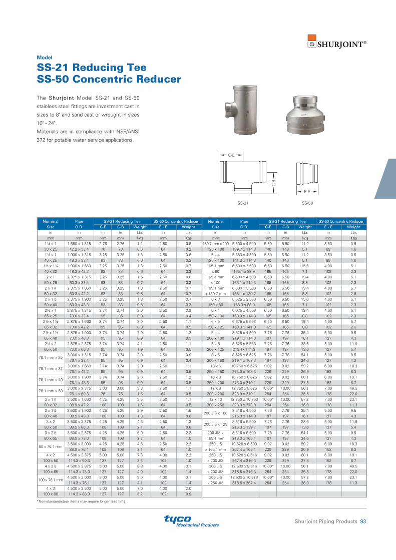
Mechanical ProductsShurjoint Piping Products 93
The Shurjoint Model SS-21 and SS-50
stainless steel fittings are investment cast in
sizes to 8" and sand cast or wrought in sizes
10" - 24".
Materials are in compliance with NSF/ANSI
372 for potable water service applications.
Model
SS-21 Reducing TeeSS-50 Concentric Reducer
Nominal Pipe SS-21 Reducing Tee SS-50 Concentric Reducer Size O.D. C-E C-B Weight E - E Weight
in in in in Lbs in Lbs mm mm mm mm Kgs mm Kgs
1¼ x 1 1.660 x 1.315 2.76 2.76 1.2 2.50 0.530 x 25 42.2 x 33.4 70 70 0.6 64 0.2 1½ x 1 1.900 x 1.315 3.25 3.25 1.3 2.50 0.640 x 25 48.3 x 33.4 83 83 0.6 64 0.31½ x 1¼ 1.900 x 1.660 3.25 3.25 1.3 2.50 0.740 x 32 48.3 x 42.2 83 83 0.6 64 0.3
2 x 1 2.375 x 1.315 3.25 3.25 1.5 2.50 0.850 x 25 60.3 x 33.4 83 83 0.7 64 0.32 x 1¼ 2.375 x 1.660 3.25 3.25 1.8 2.50 0.750 x 32 60.3 x 42.2 83 83 0.8 64 0.72 x 1½ 2.375 x 1.900 3.25 3.25 1.8 2.50 0.750 x 40 60.3 x 48.3 83 83 0.8 64 0.32½ x 1 2.875 x 1.315 3.74 3.74 2.0 2.50 0.965 x 25 73.0 x 33.4 95 95 0.9 64 0.42½ x 1¼ 2.875 x 1.660 3.74 3.74 2.0 2.50 1.165 x 32 73.0 x 42.2 95 95 0.9 64 0.52½ x 1½ 2.875 x 1.900 3.74 3.74 2.0 2.50 1.265 x 40 73.0 x 48.3 95 95 0.9 64 0.52½ x 2 2.875 x 2.375 3.74 3.74 4.1 2.50 1.165 x 50 73.0 x 60.3 95 95 1.9 64 0.5
76.1 mm x 253.000 x 1.315 3.74 3.74 2.0 2.50 0.9
76.1 x 33.4 95 95 0.9 64 0.4
76.1 mm x 323.000 x 1.660 3.74 3.74 2.0 2.50 1.1
76.1 x 42.2 95 95 0.9 64 0.5
76.1 mm x 403.000 x 1.900 3.74 3.74 2.0 2.50 1.2
76.1 x 48.3 95 95 0.9 64 0.5
76.1 mm x 503.000 x 2.375 3.00 3.00 3.3 2.50 1.1
76.1 x 60.3 76 76 1.5 64 0.53 x 1¼ 3.500 x 1.660 4.25 4.25 3.5 2.50 1.180 x 32 88.9 x 42.2 108 108 1.6 64 0.53 x 1½ 3.500 x 1.900 4.25 4.25 2.9 2.50 1.580 x 40 88.9 x 48.3 108 108 1.3 64 0.6
3 x 2 3.500 x 2.375 4.25 4.25 4.6 2.50 1.380 x 50 88.9 x 60.3 108 108 2.1 64 0.63 x 2½ 3.500 x 2.875 4.25 4.25 6.0 2.50 2.280 x 65 88.9 x 73.0 108 108 2.7 64 1.0
80 x 76.1 mm3.500 x 3.000 4.25 4.25 4.6 2.50 2.2
88.9 x 76.1 108 108 2.1 64 1.04 x 2 4.500 x 2.375 5.00 5.00 7.3 4.00 2.2
100 x 50 114.3 x 60.3 127 127 3.3 102 1.04 x 2½ 4.500 x 2.875 5.00 5.00 8.8 4.00 3.1
100 x 65 114.3 x 73.0 127 127 4.0 102 1.4
100 x 76.1 mm4.500 x 3.000 5.00 5.00 9.0 4.00 3.1 114.3 x 76.1 127 127 4.1 102 1.4
4 x 3 4.500 x 3.500 5.00 5.00 7.0 4.00 2.0100 x 80 114.3 x 88.9 127 127 3.2 102 0.9
Nominal Pipe SS-21 Reducing Tee SS-50 Concentric Reducer Size O.D. C-E C-B Weight E - E Weight
in in in in Lbs in Lbs mm mm mm mm Kgs mm Kgs 139.7 mm x 100 5.500 x 4.500 5.50 5.50 11.2 3.50 3.5
125 x 100 139.7 x 114.3 140 140 5.1 89 1.65 x 4 5.563 x 4.500 5.50 5.50 11.2 3.50 3.5
125 x 100 141.3 x 114.3 140 140 5.1 89 1.6165.1 mm 6.500 x 3.500 6.50 6.50 15.6 4.00 5.1
x 80 165.1 x 88.9 165 165 7.1 102 2.3165.1 mm 6.500 x 4.500 6.50 6.50 19.4 4.00 5.1
x 100 165.1 x 114.3 165 165 8.8 102 2.3165.1 mm 6.500 x 5.500 6.50 6.50 19.4 4.00 5.7
x 139.7 mm 165.1 x 139.7 165 165 8.8 102 2.66 x 3 6.625 x 3.500 6.50 6.50 15.6 4.00 5.1
150 x 80 168.3 x 88.9 165 165 7.1 102 2.36 x 4 6.625 x 4.500 6.50 6.50 19.4 4.00 5.1
150 x 100 168.3 x 114.3 165 165 8.8 102 2.36 x 5 6.625 x 5.563 6.50 6.50 19.4 4.00 5.7
150 x 125 168.3 x 141.3 165 165 8.8 102 2.68 x 4 8.625 x 4.500 7.76 7.76 35.4 5.00 9.5
200 x 100 219.1 x 114.3 197 197 16.1 127 4.38 x 5 8.625 x 5.563 7.76 7.76 28.6 5.00 11.9
200 x 125 219.1x 141.3 197 197 13.0 127 5.48 x 6 8.625 x 6.625 7.76 7.76 54.1 5.00 9.5
200 x 150 219.1 x 168.3 197 197 24.6 127 4.310 x 6 10.750 x 6.625 9.02 9.02 59.2 6.00 18.3
250 x 150 273.0 x 168.3 229 229 26.9 152 8.310 x 8 10.750 x 8.625 9.02 9.02 60.1 6.00 19.1
250 x 200 273.0 x 219.1 229 229 27.3 152 8.712 x 8 12.750 x 8.625 10.00* 10.00 56.1 7.00 49.5
300 x 200 323.9 x 219.1 254 254 25.5 178 22.012 x 10 12.750 x 10.750 10.00* 10.00 57.2 7.00 23.1
300 x 250 323.9 x 273.0 254 254 26.0 178 11.3
200 JIS x 1008.516 x 4.500 7.76 7.76 35.4 5.00 9.5216.3 x 114.3 197 197 16.1 127 4.3
200 JIS x 1258.516 x 5.500 7.76 7.76 28.6 5.00 11.9216.3 x 139.7 197 197 13.0 127 5.4
200 JIS x 8.516 x 6.500 7.76 7.76 54.1 5.00 9.5165.1 mm 216.3 x 165.1 197 197 24.6 127 4.3
250 JIS 10.528 x 6.500 9.02 9.02 59.2 6.00 18.3x 165.1 mm 267.4 x 165.1 229 229 26.9 152 8.3
250 JIS 10.528 x 8.516 9.02 9.02 60.1 6.00 19.1x 200 JIS 267.4 x 216.3 229 229 27.3 152 8.7300 JIS 12.539 x 8.516 10.00* 10.00 56.1 7.00 49.5
x 200 JIS 318.5 x 216.3 254 254 25.5 178 22.0 300 JIS 12.539 x 10.528 10.00* 10.00 57.2 7.00 23.1
x 250 JIS 318.5 x 267.4 254 254 26.0 178 11.3
*Non-standard/stock items may require longer lead time.
SS-21 SS-50
C-B
C-E
E-E

Mechanical Products94 Shurjoint Piping Products
The Shurjoint Model SS-21F and SS-50F
stainless steel fittings are investment cast in
sizes from 2½” to 4”.
Materials are in compliance with NSF/ANSI
372 for potable water service applications.
Model
SS-21F Reducing Tee (GR X GR X FT)SS-50F Concentric Reducer (GR X FT)
Nominal Pipe SS-21F Reducing Tee SS-50F Concentric Reducer Size O.D. C-E C-B Weight E-E Weight mm mm mm mm Kgs mm Kgs 65 x 40F 73.0/76.1 x 48.3 76 76 0.83 --- --- 65 x 50F 73.0/76.1 x 60.3 --- --- --- 89 0.95 80 x 50F 88.9 x 60.3 95 95 2.10 89 0.92 100 x 50F 114.3 x 60.3 114 114 3.20 102 1.76
* FT: BSP female threaded
SS-21F SS-50F
C-B
C-E
E-E
BSP female threaded
BSP female threaded

Mechanical ProductsShurjoint Piping Products 95
The Model SS-41 stainless steel flange adapter
allows for a direct connection with ANSI Class
125/150 flanges. The SS-41 is investment
cast in Gr. CF8 (304) or CF8M (316). Integral
closure tabs located on the flange O.D. help
facilitate alignment and assembly.
Model
SS-41 Flange Adapter - ANSI 125/150
Contact Shurjoint for other sizes.*Non-standard/stock items may require longer lead time.
Nominal Pipe Y: Flange Drilling Bolt Size O.D. L X ANSI 125 / 150 PN 10 PN16 JIS 10K Z ANSI 125 / 150 PN 10 PN16 JIS 10K Weight in in in in in in in in in Size Size Size Size Lbs mm mm mm mm mm mm mm mm mm No. No. No. No. Kgs 2 2.375 2.50 6.50 4.75 4.92 4.92 4.72 0.63 ⅝ M16 M16 M16 4.4 50 60.3 64 165 121 125 125 120 16 4 4 4 4 2.0 2½* 2.875 3.00 7.28 5.50 5.70 5.70 5.50 0.63 ⅝ ---
---
--- 6.4
65 73.0 76 185 140 145 145 140 16 4 --- --- --- 2.9
76.1 mm 3.000 3.00 7.28 5.50 5.70 5.70 5.50 0.63 --- M16 M16 M16 6.6
76.1 76 185 140 145 145 140 16 --- 4 4 4 3.0 3 3.500 2.95 7.78 6.00 6.30 6.30 5.90 0.63 ⅝ M16 M16 M16 7.5 80 88.9 75 200 152 160 160 150 16 8 8 8 8 3.4 4 4.500 2.95 8.86 7.50 7.09 7.09 6.89 0.63 ⅝ M16 M16 M16 8.6 100 114.3 75 225 191 180 180 175 16 8 8 8 8 3.9 139.7 mm*
5.500 2.95 10.00 8.50 8.27 8.27 8.27 0.63 --- M16 M16 M20 14.7 139.7 75 254 216 210 210 210 16 --- 8 8 8 6.7 5 5.563 2.95 10.00 8.50 8.27 8.27 8.27 0.87 ¾ ---
---
--- 14.7
125 141.3 75 254 216 210 210 210 22 8 --- --- --- 6.7 165.1 mm*
6.500 2.95 10.71 9.50 9.45 9.45 9.45 0.63 --- M20 M20 M20 15.0 165.1 75 272 241 240 240 240 16 --- 8 8 8 6.8 6 6.625 2.95 10.71 9.50 9.45 9.45 9.45 0.63 ¾ ---
---
--- 15.2
150 168.3 75 272 241 240 240 240 16 8 --- --- --- 6.9 8 8.625 4.00 13.50 11.75 11.61 11.61 --- 0.87 ¾ M20 M20 --- 31.9 200 219.1 102 343 298 295 295 --- 22 8 8 16 --- 14.5
200 JIS 8.516 4.00 13.50 11.75 11.61 11.61 11.42 0.87 --- --- --- M20 30.8
216.3 102 343 298 295 295 290 22 --- --- --- 12 14.0 10 10.750 3.94 16.00 14.25 13.77 14.00 14.00 1.18 ⅞ M20 M24 M22 49.6 250 273.0 100 406 362 350 355 355 30 12 12 12 12 22.5 12* 12.750 4.45 19.00 17.00 15.75 16.14 --- 1.26 ⅞ M20 M24 --- 65.9 300 323.9 113 483 432 400 410 --- 32 12 12 12 --- 29.9
Max. Max. Nominal Pipe Working Pressure End Load
Dimensions Sealing Surface Bolt Weight
Size O.D. (CWP)* (CWP) A B C D E Size in in PSI Lbs in in in in in
No. in Lbs
mm mm Bar kN mm mm mm mm mm Kgs 2 2.375 300 1330 6.00 4.75 0.75 2.28 3.07
4 ⅝ x 3 4.6
50 60.3 20 5.71 152 121 19 58 78 2.1 2½ 2.875 300 1950 7.00 5.50 0.87 2.72 3.54
4 ⅝ x 3 6.0
65 73.0 20 8.37 178 140 22 69 90 2.7 3 3.500 300 2880 7.52 6.00 0.94 3.35 4.17
4 ⅝ x 3 6.8
80 88.9 20 12.41 191 152 24 85 106 3.1 4 4.500 300 4770 9.00 7.50 0.94 4.33 5.20
8 ⅝ x 3 9.9
100 114.3 20 20.51 229 191 24 110 132 4.5 6 6.625 300 10340 11.00 9.50 1.00 6.46 7.32
8 ¾ x 3½ 12.9
150 168.3 20 44.47 279 241 25 164 186 5.8 8 8.625 300 17520 13.50 11.75 1.14 8.46 9.29
8 ¾ x 3½ 20.2
200 219.1 20 75.37 343 298 29 215 236 9.2
* The working pressure shown is based on roll-grooved Sch. 40S pipe.
2"~12"(hinged)
B
AC
ED
The Model SS-80 Universal Flange Adapter
provides for a rigid transition between a grooved
piping system and a flanged piping system or
component. The SS-80 can mate to ANSI
125/150, PN 10/16, BS-10E or JIS 10K, and is
available standard in CF8 (304) or CF8M (316).
Model
SS-80 Stainless Steel Universal Flange AdapterZ
X Y D
L

Mechanical Products96 Shurjoint Piping Products
The Shurjoint Model SS-723 stainless steel
mechanical tee is the ideal fitting for branch
or direct outlet connections to sprinkler
heads, drop nipples and or gauges on
stainless steel pipe. No need for welding,
Model
SS-723 Stainless Steel Mechanical Tee
* Working pressure is based on standard wall stainless steel pipe. Hole diameters listed are suggested hole diameters. T: Take-out (Center of run to end of pipe to be engaged)
Max. Dimensions
Nominal Working Hole Dia. Bolt Size Pressure +0.063, -0 / Size Weight Run x Branch (CWP)* +1.6, -0 A B C D T in PSI in in in in in in
in Lbs
mm Bar mm mm mm mm mm mm Lbs 1¼ x ½ 300 1.18 1.60 1.02 3.44 1.93 1.06
5/16 x 1½ 0.7
32 x 15 20 30 41 26 87 49 27 0.3 1¼ x ¾ 300 1.18 1.70 1.02 3.44 1.93 1.14
5/16 x 1½ 0.7
32 x 20 20 30 44 26 87 49 29 0.3 1¼ x 1 300 1.18 2.00 1.02 3.44 1.93 1.34
5/16 x 1½ 0.9
32 x 25 20 30 51 26 87 49 34 0.4 1½ x ½ 300 1.18 1.70 1.13 3.54 1.93 1.18
5/16 x 1½ 0.7
40 x 15 20 30 44 29 90 49 30 0.3 1½ x ¾ 300 1.18 1.81 1.13 3.54 1.93 1.22
5/16 x 1½ 0.7
40 x 20 20 30 46 29 90 49 31 0.3 1½ x 1 300 1.18 2.09 1.13 3.54 1.93 1.42
5/16 x 1½ 0.9
40 x 25 20 30 53 29 90 49 36 0.4 2 x ½ 300 1.18 2.00 1.42 4.28 2.00 1.46
5/16 x 1½ 1.1
50 x 15 20 30 51 36 109 51 37 0.5 2 x ¾ 300 1.18 2.09 1.42 4.28 2.00 1.10
5/16 x 1½ 1.1
50 x 20 20 30 53 36 109 51 28 0.5 2 x 1 300 1.18 2.37 1.42 4.28 2.00 1.69
5/16 x 1½ 1.4
50 x 25 20 30 60 36 109 51 43 0.6
simply cut or drill a hole at the desired
location, position the housing so that the
locating collar fits within the hole and secure
with the bolts and nuts.
D
B
A
C
T

Mechanical ProductsShurjoint Piping Products 97
The Model SS-726 Stainless Steel Grooved-
end Y-Strainers are designed to strain debris
and foreign matter from piping systems
and thus provide inexpensive protection
for costly pumps, meters and other
Model
SS-726 Stainless Steel Y-Strainer
Max. Dimensions
Nominal Pipe Working Drain Plug Size O.D. Pressure Size Weight (CWP)* A B C in in PSI in in in in Lbs mm mm Bar mm mm mm mm Kgs 2½ 2.875 300 10.75 7.83 4.80 ½ 16.7 65 73.0 20 273 199 122 15 7.6 3 3.500 300 11.75 8.70 5.08 ½ 18.9 80 88.9 20 299 221 129 15 8.6 4 4.500 300 14.25 10.59 6.61 1 21.1 100 114.3 20 362 269 168 25 9.6 6 6.625 300 18.50 14.05 8.62 1 85.8 150 168.3 20 470 357 219 25 39.0
* Working pressure is based on connection with roll- or cut-grooved standard wall stainless steel pipe.
components. Cleaning and maintenance of
the screen can be accomplished easily by
removing the coupling. The Model SS-726
Stainless Steel Y-Strainer is suitable for
vertical or horizontal installations.
2"~12"
A
BC

Mechanical Products98 Shurjoint Piping Products
1½" - 3"
4"
Nominal Pipe Dimensions Size O.D. K H W Weight in in in in in Lbs mm mm mm mm mm Kgs 2 2.375 5.98 5.38 8.00 17.82 50 60.3 152 137 203 8.10 2½ 2.875 5.98 5.68 8.00 24.42 65 73.0 152 145 203 11.10
76.1 mm 3.000 5.98 5.68 8.00 24.42
76.1 152 145 203 11.10 3 3.500 5.98 7.16 8.00 29.70 80 88.9 152 182 203 13.50 4 4.500 5.98 8.00 8.00 63.80 100 114.3 152 203 203 29.0
* The weight includes the worm gear operator.
The Model SJ-600L is a two-piece, full-
port stainless steel ball valve rated at
600 psi (42 Bar) and is available in CF8M
(316). The SJ-600L features a floating ball
for lower torque and is supplied with a lever
handle as well as ISO mounting holes to
accommodate a full range of gear or power
actuators.
The Model SJ-600W is supplied with a worm
gear operator. The standard gear operator is
supplied with a bracket and extension sleeve.
Sizes available are 2" (50 mm) through 4"
(100 mm).
Model
SJ-600L Ball Valve
Model
SJ-600W Ball Valve
* Working pressure is for connection with cut- or roll-grooved schedule Sch. 40S pipe. For the first opening or closing of the valve when the valve is not continuously operated, an additional torque of 2.0 – 2.5 times the listed operating torque is normally required.
^ The weight includes the lever handle.
Max. Nominal Pipe Working Operating
Dimensions
Size O.D. Pressure Torque Weight^ (CWP)* L H W d in in PSI Lbs-in in in in in Lbs mm mm Bar Nm mm mm mm mm Kgs 1½ 1.900 600 62 5.50 3.70 7.60 1.50 6.6 40 48.3 42 7 140 94 193 38 3.0 2 2.375 600 150 6.15 4.13 7.60 1.97 8.8 50 60.3 42 17 156 105 193 50 4.0 2½ 2.875 600 186 7.09 4.33 9.84 2.56 15.4 65 73.0 42 21 180 110 250 65 7.0
76.1 mm 3.000 600 186 7.09 4.33 9.84 2.56 15.4
76.1 42 21 180 110 250 65 7.0 3 3.500 600 248 8.42 6.00 9.84 3.07 20.7 80 88.9 42 28 214 152 250 78 9.4 4 4.500 600 398 9.45 6.57 11.42 3.94 55.0 100 114.3 42 45 240 167 290 100 25.0
H
d
W
L
K
W
H

Mechanical ProductsShurjoint Piping Products 99
The Shurjoint Model SJ-400 Butterfly Valve
is a grooved end stainless steel butterfly
valve, supplied with a 10 position lever
handle (SJ-400L) or worm gear operator
can be supplied as an option (SJ-400W).
The body is available in CF8M (316) to
Model
SJ-400 Butterfly Valve
ASTM A743 with integral neck and ISO
5211 mounting pad. It features a dual seal
disc encapsulated with Gr. E-pw EPDM for
cold and hot water services. The end-to-end
dimensions conform to MSS SP-67.
Max. Dimensions
Nominal Pipe Working Operating Size O.D. Pressure Torque Weight (CWP)** A B C D E in in PSI in in in in in Lbs-in Lbs mm mm Bar mm mm mm mm mm Nm Kgs 2 2.375 300 3.19 2.520 2.480 4.17 7.56 78 5.0 50 60.3 20 81 64 63 106 192 8.80 2.3 2½ 2.875 300 3.81 3.150 2.677 4.28 7.56 84 7.0 65 73.0 20 97 80 68 111 192 9.50 3.2
76.1 mm* 3.000 300 3.81 3.150 2.677 4.28 7.56 84 7.0
76.1 20 97 80 68 111 192 9.50 3.2 3 3.500 300 3.81 3.622 2.992 4.97 7.56 95 6.6 80 88.9 20 97 92 76 126 192 10.7 3.5 4 4.500 300 4.56 4.646 3.504 5.33 9.92 200 11.0 100 114.3 20 116 118 89 135 252 22.6 5.0
165.1 mm* 6.500 300 5.81 6.772 4.488 6.62 9.92 310 20.2
165.1 20 148 172 114 168 252 34.9 9.2 6 6.625 300 5.81 6.772 4.488 7.25 13.46 310 20.2 150 168.3 20 148 172 114 184 342 34.9 9.2
200 JIS* 8.516 300 5.24 8.740 5.512 8.20 13.46 400 26.8
216.3 20 133 222 140 208 342 45.1 12.2 8 8.625 300 5.24 8.740 5.512 8.20 13.46 400 26.8 200 219.1 20 133 222 140 208 342 45.1 12.2
The weight includes the lever handle.* Non-standard/stock items may require longer lead time.** Working pressure is based on connection with roll- or cut-grooved standard wall stainless steel pipe.
SJ-400-L2“- 8”
S
O
AB
DC
E
O.D
.
SJ-400-W2“- 8”
DC
E
A B
O.D
.

Mechanical Products100 Shurjoint Piping Products
Nominal Pipe Max. Working Dimensions Size O.D. Pressure (CWP)* L H W d A B Weight in in PSI in in in in in in Lbs mm mm Bar mm mm mm mm mm mm Kgs 2 2.375 600 6.55 4.32 8.96 1.50 3.25 3.13 7.89 50 60.3 42 167 110 228 38 83 79 3.58
The Shurjoint Model SJ-630 is a grooved-
end three-port ball valve designed to divert
media from bottom inlet to either of the
two outlets ports. The valve port is a
regular port size and the stem features a
Model
SJ-630 Three Port Ball Valve
blowout proof design to MSS SP-72 and
API Standard 608. The valve body and trim
materials are in compliance with NACE
MR-01-75 requirements.
d
W
O.D
.B
HA
L
* Working pressure is based on connection with roll- or cut-grooved Sch. 40S stainless steel pipe.

Mechanical ProductsShurjoint Piping Products 101
The following tables show maximum cold working pressures (CWP)
of Shurjoint stainless steel couplings used on stainless steel pipes.
In general it is more difficult to achieve defined groove corners on
stainless steel pipe than on carbon steel pipe. Always select the
correct roll set for the pipe being grooved and process grooves as
defined as possible. Contact your roll-groove tool manufacturer for
recommendations.
Pressure Performance DataStainless Steel Couplings on Stainless Steel Pipe
Model SS-7 Rigid Coupling Model SS-5 Rigid Coupling
Model SS-7X Rigid Coupling
Nom. Cut-Grooved Roll-Grooved Size Sch. 40S Sch. 40S Sch. 10S Sch. 5S in psi psi psi psi mm Bar Bar Bar Bar 10 600 600 300 200 250 42 42 20 14 12 600 600 300 200 300 42 42 20 14 14 400 400 300 200 350 28 28 20 14 16 400 400 300 200 400 28 28 20 14 18 350 350 300 200 450 24 24 20 14 20 350 350 300 200 500 24 24 20 14 22 300 300 300 200 550 20 20 20 14 24 300 300 300 200 600 20 20 20 14
Nom. Cut-Grooved Roll-Grooved Size Sch. 40S Sch. 40S Sch. 10S Sch. 5S in psi psi psi psi mm Bar Bar Bar Bar 1¼ 600 600 300 200 32 42 42 20 14 1½ 600 600 300 200 40 42 42 20 14 2 600 600 300 200 50 42 42 20 14 2½ 600 600 300 200 65 42 42 20 14 3 600 600 300 200 80 42 42 20 14 4 600 600 300 200 100 42 42 20 14 5 600 600 300 200 125 42 42 20 14 6 600 600 300 200 150 42 42 20 14 8 600 600 300 200 200 42 42 20 14
Nom. Cut-Grooved Roll-Grooved Size Sch. 40S Sch. 40S Sch. 10S Sch. 5S in psi psi psi psi mm Bar Bar Bar Bar 1¼ 600 600 300 200 32 42 42 20 14 1½ 600 600 300 200 40 42 42 20 14 2 600 600 300 200 50 42 42 20 14 2½ 600 600 300 200 65 42 42 20 14 3 600 600 300 200 80 42 42 20 14 4 600 600 300 200 100 42 42 20 14 5 600 600 300 200 125 42 42 20 14 6 600 600 300 200 150 42 42 20 14 8 600 600 300 200 200 42 42 20 14

Mechanical Products102 Shurjoint Piping Products
Model SS-8 Flexible Coupling
Model SS-8X Heavy Duty Flexible Coupling
Nom. Cut-Grooved Roll-Grooved Size Sch. 40S Sch. 40S Sch. 10S Sch. 5S in psi psi psi psi mm Bar Bar Bar Bar ¾ 750 750 500 200 20 52 52 35 14 1 750 750 500 200 25 52 52 35 14 1¼ 750 750 500 200 32 52 52 35 14 1½ 750 750 500 200 40 52 52 35 14 2 750 750 500 200 50 52 52 35 14 2½ 750 750 500 200 65 52 52 35 14 3 750 750 500 200 80 52 52 35 14 4 750 750 300 200 100 52 52 20 14 5 750 300 300 200 125 52 20 20 14 6 300 300 300 200 150 20 20 20 14 8 300 300 300 200 200 20 20 20 14
Nom. Cut-Grooved Roll-Grooved Size Sch. 40S Sch. 40S Sch. 10S Sch. 5S in psi psi psi psi mm Bar Bar Bar Bar 1 500 500 350 225 25 35 35 24 16 1¼ 500 500 350 225 32 35 35 24 16 1½ 500 500 350 225 40 35 35 24 16 2 500 500 350 225 50 35 35 24 16 2½ 500 500 350 225 65 35 35 24 16 3 500 500 350 225 80 35 35 24 16 4 325 325 300 200 100 22 22 20 14 5 200 200 200 125 125 14 14 14 9 6 200 200 200 125 150 14 14 14 9 8 200 200 200 125 200 14 14 14 9
Nom. Cut-Grooved Roll-Grooved Size Sch. 40S Sch. 40S Sch. 10S Sch. 5S in psi psi psi psi mm Bar Bar Bar Bar 1½ 300 300 300 200 40 20 20 20 14 2 300 300 300 200 50 20 20 20 14 2½ 300 300 300 200 65 20 20 20 14 3 300 300 300 200 80 20 20 20 14 4 300 300 300 200 100 20 20 20 14 5 200 200 200 125 125 14 14 14 9 6 200 200 200 125 150 14 14 14 9
Model SS-28 Hinged Lever Coupling
Nom. Cut-Grooved Size in / mm Sch. 80S Sch. 40S in psi psi mm Bar Bar ¾ 1200 1200 20 83 83 1 1200 1200 25 83 83 1¼ 1200 1200 32 83 83 1½ 1200 1200 40 83 83 2 1200 1200 50 83 83 2½ 1200 1200 65 83 83 3 1200 1200 80 83 83 4 1200 1200 100 83 83
Model SS-1200 High Pressure Flexible Coupling
Burst pressure: 2 times the listed working pressure.

Mechanical ProductsShurjoint Piping Products 103
Notes

Mechanical Products104 Shurjoint Piping Products
Notes

Mechanical ProductsShurjoint Piping Products 105
Valves & Flow Control Components ....................................... 106
SJ-200 Low-Profile Butterfly Valve ................................................... 107
SJ-300N Butterfly Valve .................................................................... 108
SJ-300F Butterfly Valve (for Fire Protection) ..................................... 110
SJ-500L Ball Valves ........................................................................... 111
SJ-500W Ball Valves .......................................................................... 112
SJ-530 Three Port Ball Valve ............................................................. 112
SJ-900 Swing Check Valve ................................................................ 113
SJ-915 Dual Disc Check Valve ........................................................... 114
SJ-930 Horizontal Swing Check Valve ............................................... 115
650N Expansion Joint ........................................................................ 116
651 Expansion Joint .......................................................................... 117
725G Suction Diffuser ....................................................................... 118
725F Suction Diffuser (Fabricated) .................................................... 119
726 Y-Strainer .................................................................................... 120
728 T-Strainer .................................................................................... 121
RCV Riser Check Valve (for Fire Protection) ...................................... 122
BH-22C Brass Swing Check Valve .................................................... 122
Section 4
Valves & Flow Control Components

Mechanical Products106 Shurjoint Piping Products
Valves and Flow Control Components
Shurjoint offers a wide range of grooved-end butterfly valves, bal l va lves, check valves, suction diffusers, strainers and expansion joints. Grooved-end valves and components can be installed 3 – 4 times faster than comparable flange components. With the removal of just a few bolts one can easily access the system for cleaning, maintenance, changes and or system expansion.
SJ-300N Butterfly Valve726 Y-Strainer7110LR 90° Elbow7180 Universal Flange Adapter7041 Flange Adapter7150 Concentric ReducerSJ-900 Swing Check Valve7707 Flexible CouplingZ07 Rigid Coupling7721 Mechanical Tee with Pressure Gage
SJ-300N Butterfly Valve725G Suction Diffuser7041 Flange Adapter7150 Concentric ReducerSJ-915 Dual Disc Check Valve7707 Flexible CouplingZ07 Rigid Coupling7721 Mechanical Tee with Pressure Gage

Mechanical ProductsShurjoint Piping Products 107
Not Recommended for Steam.
The Shurjoint Model SJ-200 Butterfly Valve
is a low profile, grooved-end butterfly valve
designed for oil & gas, mining and other
service applications. The working pressure
is rated up to 232 psi / 1600 kPa and service
temperatures are rated to +180°F / +82°C
Model
SJ-200 Low-Profile Butterfly Valve
(Nitrile body liner). The Model SJ-200
features a fully rubber lined body with
316 stainless steel disc. The end to end
dimensions conform to MSS SP-67. The
lever handle is equipped with a tamper
resistant locking device.
Nominal Pipe Max. Working Dimensions Size O.D. Pressure (CWP)* A B C H Weight in in PSI in in in in Lbs mm mm Bar mm mm mm mm Kgs 2 2.375 232 3.19 1.89 2.25 5.51 2.0 50 60.3 16 81 48 57 140 0.9 2½ 2.875 232 3.82 2.13 2.65 7.48 3.3 65 73.0 16 97 54 67 190 1.5 3 3.500 232 3.82 2.44 2.94 7.48 4.2 80 88.9 16 97 62 75 190 1.9 4 4.500 232 4.57 3.00 3.82 10.79 8.6 100 114.3 16 116 76 97 274 3.9 6 6.625 232 5.83 4.09 4.57 10.79 22.2 150 168.3 16 148 104 116 274 10.1 8 8.625 232 5.25 5.50 6.00 10.79 27.9 200 219.1 16 133 140 152 274 11.3
* Working pressure is based on connection with roll- or cut-grooved standard wall carbon steel pipe.
O.D.
H
C
B
A

Mechanical Products108 Shurjoint Piping Products
Dual-Seal
SJ-300N-Lw / lever handle
The Shurjoint Model SJ-300N Butterfly
Valve is a grooved-end shut-off valve
equipped with a 10 position lever handle
(SJ-300N-L) or worm gear operator
(SJ-300N-W). The valve consists of an epoxy
coated ductile iron body and EPDM or Nitrile
Model
SJ-300N-L Butterfly Valve
(NBR) rubber encapsulated dual-seal disc.
Model SJ-300N is UL classified in accordance
with NSF/ANSI 61 and NSF/ANSI 372 for cold
+74°F (+23°C) potable water services with
"E-pw" encapsulated disc. The end-to-end
dimensions conform to MSS SP-67.
Max.Dimensions
Nominal Pipe Working Operating Size O.D. Pressure Torque Weight
(CWP)* A B C D E in in PSI in in in in in Lbs-in Lbs mm mm Bar mm mm mm mm mm Nm Kgs 2 2.375 300 3.19 2.52 2.48 4.17 7.56 80 6.8 50 60.3 20 81 64 63 106 192 9 3.1 2½ 2.875 300 3.82 3.11 2.68 4.37 7.56 120 8.2 65 73.0 20 97 79 68 111 192 14 3.7
76.1 mm3.000 300 3.82 3.11 2.68 4.37 7.56 120 8.476.1 20 97 79 68 111 192 14 3.8
3 3.500 300 3.82 3.62 2.99 4.96 7.56 160 9.0 80 88.9 20 97 92 76 126 192 18 4.1
4 4.500 300 4.57 4.65 3.50 5.32 10.24 450 11.4 100 114.3 20 116 118 89 135 260 51 5.2
139.7 mm5.500 300 5.83 5.71 4.02 6.61 10.24 700 16.9139.7 20 148 145 102 168 260 79 7.7
5 5.563 300 5.83 5.71 4.02 6.61 10.24 700 16.9 125 141.3 20 148 145 102 168 260 79 7.7
165.1 mm6.500 300 5.83 6.77 4.49 7.24 10.24 900 20.2165.1 20 148 172 114 184 260 102 9.2
6 6.625 300 5.83 6.77 4.49 7.24 10.24 900 20.2 150 168.3 20 148 172 114 184 260 102 9.2
200 JIS8.516 300 5.24 8.74 5.51 8.19 10.24 1200 26.8216.3 20 133 222 140 208 260 136 12.2
8 8.625 300 5.24 8.74 5.51 8.19 10.24 1200 26.8 200 219.1 20 133 222 140 208 260 136 12.2 10 10.750 300 6.25 10.86 6.69 9.25 14.02 1800 48.4 250 273.0 20 159 276 170 235 356 204 22.0 12 12.750 300 6.53 12.87 8.07 10.24 14.02 2500 73.7 300 323.9 20 165 327 205 260 356 282 33.5
* Working pressure is based on connection with roll- or cut-grooved standard wall carbon steel pipe. The weight includes the lever handle.
Notes: The torque values are based on liquid applications. For dry or non-lubricating applications add a 25% service factor to the above values.
S
O
D
C
B
O.D.
A
E

Mechanical ProductsShurjoint Piping Products 109
SJ-300N-Ww / worm gear
The Model SJ-300N can be equipped
with a worm gear operator. The ISO 5211
mounting pad allows for the mounting of
power actuators.
Model
SJ-300N-W Butterfly Valve
Max. Dimensions
Nominal Pipe Working Size O.D. Pressure Weight (CWP)* A B C D E F in in PSI in in in in in in Lbs mm mm Bar mm mm mm mm mm mm Kgs 2 2.375 300 3.19 2.52 2.48 4.17 6.00 6.00 13.6 50 60.3 20 81 64 63 106 152 152 6.2 2½ 2.875 300 3.82 3.11 2.68 4.37 6.00 6.00 14.3 65 73.0 20 97 79 68 111 152 152 6.5
76.1 mm 3.000 300 3.82 3.11 2.68 4.37 6.00 6.00 14.3
76.1 20 97 79 68 111 152 152 6.5 3 3.500 300 3.82 3.62 2.99 4.96 6.00 6.00 16.0 80 88.9 20 97 92 76 126 152 152 7.3 4 4.500 300 4.57 4.65 3.50 5.32 6.00 6.00 19.1 100 114.3 20 116 118 89 135 152 152 8.7
139.7 mm 5.500 300 5.83 5.71 4.02 6.61 6.00 6.00 21.8
139.7 20 148 145 102 168 152 152 9.9 5 5.563 300 5.83 5.71 4.02 6.61 6.00 6.00 21.8 125 141.3 20 148 145 102 168 152 152 9.9
165.1 mm 6.500 300 5.83 6.77 4.49 7.24 6.00 6.00 25.0
165.1 20 148 172 114 184 152 152 11.4 6 6.625 300 5.83 6.77 4.49 7.24 6.00 6.00 25.3 150 168.3 20 148 172 114 184 152 152 11.5
200 JIS 8.516 300 5.24 8.74 5.51 8.19 6.00 6.00 31.9
216.3 20 133 222 140 208 152 152 14.5 8 8.625 300 5.24 8.74 5.51 8.19 6.00 6.00 32.0 200 219.1 20 133 222 140 208 152 152 14.5 10 10.750 300 6.25 10.86 6.69 9.25 8.00 8.00 59.4 250 273.0 20 159 276 170 235 203 203 27.0 12 12.750 300 6.53 12.87 8.07 10.24 8.00 8.00 73.7 300 323.9 20 165 327 205 260 203 203 33.5 14 14.000 300 7.00 14.37 8.82 10.86 9.50 12.00 130.0 350 355.6 20 178 365 224 276 242 306 59.0 16 16.000 300 7.00 16.38 9.76 11.89 9.50 12.00 147.4 400 406.4 20 178 416 248 302 242 306 67.0 18 18.000 300 8.00 18.50 11.14 13.78 9.50 12.00 189.2 450 457.2 20 203 470 283 350 242 306 86.0 20 20.000 300 8.50 20.75 12.36 15.08 11.50 16.00 292.6 500 508.0 20 216 527 314 383 290 412 133.0 22 22.000 300 9.25 22.75 13.48 16.81 11.50 16.00 324.1 550 559.0 20 235 578 343 427 290 412 147.0 24 24.000 300 10.00 24.76 14.49 17.83 11.50 16.00 352.0 600 609.6 20 254 629 368 453 290 412 160.0
* Working pressure is based on connection with roll- or cut-grooved standard wall carbon steel pipe. The weight includes the worm gear operator.
E
O.D.
A B
D
C
F

Mechanical Products110 Shurjoint Piping Products
Dual Seal
The Shurjoint Model SJ-300F Butterfly
Valve is a grooved-end shut-off valve
equipped with a weatherproof worm gear
operator and supervisory switch and wiring.
The Model SJ-300F is cULus listed and FM
approved for 300 psi (20 Bar, 2.0 MPa)
WWP (water working pressure) service for
indoor and outdoor use. Flow characteristics
Model
SJ-300F Butterfly Valve
satisfy UL Specification 1091 and FM
Approval Standard 1112.
When the Model SJ-300F Butterfly Valve is
used in a fire protection piping, installation
shall conform to NFPA 13 and NFPA 72.
The valve consists of an epoxy powder
coated ductile iron body and EPDM rubber
encapsulated dual-seal disc.
Max. Working Dimensions Nominal Pipe Pressure Weight(2)
Size O.D. (CWP) * A(1) B C D E F G in in PSI in in in in in in in Lbs mm mm Bar mm mm mm mm mm mm mm Kgs 2 2.375 300 3.19 2.56 2.48 4.17 7.87 3.62 6.42 16.70 50 60.3 20 81 65 63 106 200 92 163 7.60 2½ 2.875 300 3.81 3.15 2.68 4.37 8.27 3.62 6.42 18.26 65 73.0 20 97 80 68 111 210 92 163 8.30
76.1 mm 3.000 300 3.81 3.15 2.68 4.37 8.27 3.62 6.42 18.41
76.1 20 97 80 68 111 210 92 163 8.37 3 3.500 300 3.81 3.62 3.00 4.96 9.17 3.62 6.42 18.92 80 88.9 20 97 92 76 126 233 92 163 8.60 4 4.500 300 4.56 4.65 3.50 5.31 10.04 3.62 6.42 21.78 100 114.3 20 116 118 89 135 255 92 163 9.90
139.7 mm 5.500 300 5.81 5.71 4.00 6.61 11.85 3.62 6.42 27.08
139.7 20 148 145 102 168 301 92 163 12.31 5 5.500 300 5.81 5.71 4.00 6.61 11.85 3.62 6.42 26.84 125 141.3 20 148 145 102 168 301 92 163 12.20
165.1 mm 6.500 300 5.81 6.77 4.50 7.25 12.95 3.62 6.42 30.38
165.1 20 148 172 114 184 329 92 163 13.81 6 6.625 300 5.81 6.77 4.50 7.25 12.95 3.62 6.42 30.14 150 168.3 20 148 172 114 184 329 92 163 13.70 8 8.625 300 5.24 8.74 5.51 8.19 14.92 3.62 6.42 38.72 200 219.1 20 133 222 140 208 379 92 163 17.60
200 JIS 8.516 300 5.24 8.74 5.51 8.19 14.92 3.62 6.42 38.72
216.3 20 133 222 140 208 379 92 163 17.60 10 10.750 300 6.25 10.87 6.69 9.25 17.17 3.62 6.42 59.27 250 273.0 20 159 276 170 235 436 92 163 26.88 12 12.750 300 6.50 12.87 8.07 10.24 19.53 3.62 6.42 74.97 300 323.9 20 165 327 205 260 496 92 163 34.00
(1) End to end dimensions conforms to MSS SP-67.(2) The weight includes the worm gear operator.* Working pressure is based on connection with roll- or cut-grooved standard wall carbon steel pipe. For Fire Protection pressure rating, listing, and approval information, please refer to Data Sheet B-42 or visit SHURJOINT website, www.shurjoint.com for details or contact your SHURJOINT Representative.
F
EG D
C
O.D.
BA

Mechanical ProductsShurjoint Piping Products 111
The Shurjoint Model SJ-500L is a ductile
iron, grooved-end, two-piece, regular
port ball valve designed and tested in
conformance with MSS SP-110 and SP-72.
The lever handle is equipped with tamper
Model
SJ-500L Ball Valve
resistant locking holes. The SJ-500L is
comprised of a ductile iron body and end
cap, virgin TFE seats and chrome-plated
carbon steel trim. Also available with
stainless steel trim as an option.
* Working pressure is based on connection with roll- or cut-grooved standard wall carbon steel pipe. For the first opening or closing of the valve when the valve is not continuously operated, an additional torque of 2.0 – 2.5 times the listed operating torque is normally required.
Max. Nominal Pipe Working Operating
Dimensions
Size O.D. Pressure Torque Weight (CWP)* L H W d in in PSI Lbs-in in in in in Lbs mm mm Bar Nm mm mm mm mm Kgs 1½ 1.900 1000 62 5.12 3.39 7.00 1.25 3.9 40 48.3 69 7 130 86 178 32 1.8 2 2.375 1000 150 5.50 3.75 7.00 1.50 6.4 50 60.3 69 17 140 95 178 38 2.9 2½ 2.875 1000 186 6.25 5.20 10.43 2.00 9.7 65 73.0 69 21 159 132 265 50 4.4
76.1 mm 3.000 1000 186 6.25 5.20 10.43 2.00 9.7
76.1 69 21 159 132 265 50 4.4 3 3.500 1000 248 6.56 5.63 10.43 2.50 17.2 80 88.9 69 28 167 143 265 63 7.8 4 4.500 800 398 9.45 3.70 10.43 3.50 32.3 100 114.3 56 45 240 94 265 90 14.7
165.1 mm 6.500 800 531 10.15 8.70 23.60 4.92 90.2
165.1 56 60 258 221 600 125 41.1 6 6.625 800 531 10.15 8.70 23.60 4.92 90.2 150 168.3 56 60 258 221 600 125 41.1
O.D
.
W
L
H
d
1½" - 4"
O.D
.
W
H
L
6"
d

Mechanical Products112 Shurjoint Piping Products
Nominal Pipe Max. Working Operating Dimensions Size O.D. Pressure (CWP)* Torque L H W d A B Weight in in PSI Lbs-in in in in in in in Lbs mm mm Bar Nm mm mm mm mm mm mm Kgs 2 2.375 600 150 6.55 4.32 8.96 1.50 3.25 3.13 7.89 50 60.3 42 17 167 110 228 38 83 79 3.58
The Model SJ-500W can be equipped with
a worm gear operator. The standard gear
operator is supplied with a bracket and
extension sleeve. The ISO 5211 mounting
pad allows for the mounting of power
actuators.
Model
SJ-500W Ball Valve with Gear Operator
The Shurjoint Model SJ-530 is a grooved-
end three-port ball valve designed to divert
media from bottom inlet to either of the
two outlets ports. The valve port is a
regular port size and the stem features a
Model
SJ-530 Three Port Ball Valve
blowout proof design to MSS SP-72 and
API Standard 608. The valve body and trim
materials are in compliance with NACE
MR-01-75 requirements.
Nominal Pipe Max. Working Dimensions Size O.D. Pressure (CWP)* K H W Weight in in PSI in in in Lbs mm mm Bar mm mm mm Kgs 1½ 1.900 1000 5.98 4.88 5.98 15 40 48.3 69 152 124 152 7 2 2.375 1000 5.98 5.38 5.98 18 50 60.3 69 152 137 152 8 2½ 2.875 1000 5.98 5.68 5.98 22 65 73.0 69 152 145 152 10
76.1 mm 3.000 1000 5.98 5.68 5.98 22
76.1 69 152 145 152 10 3 3.500 1000 5.98 7.16 8.00 168 80 88.9 69 152 182 203 14 4 4.500 800 5.98 8.00 8.00 73 100 114.3 56 152 203 203 33
165.1 mm 6.500 800 12.00 10.89 9.53 123
165.1 56 305 277 242 56 6 6.625 800 12.00 10.89 9.53 123 150 168.3 56 305 277 242 56
* Working pressure is based on connection with roll- or cut-grooved standard wall carbon steel pipe.
* Working pressure is based on connection with roll- or cut-grooved standard wall carbon steel pipe. For the first opening or closing of the valve when the valve is not continuously operated, an additional torque of 2.0 - 2.5 times the listed operating torque is normally required.
K
W
H
dO.D
.
W
HA
L B

Mechanical ProductsShurjoint Piping Products 113
The Shurjoint Model SJ-900 Swing Check
Valve is a grooved-end check valve featuring
a spring-loaded wide-open clapper and a
non-stick leak tight EPDM rubber seal. With
Model
SJ-900 Swing Check Valve
a rated working pressure of 300 psi (20 Bar),
the valve can be installed in the horizontal or
vertical position (upward flow only). Valves
are tested to API 598.
Max. Dimensions
Nominal Pipe Working Size O.D. Pressure Weight (CWP)* A B C D E F in in PSI in in in in in in Lbs mm mm Bar mm mm mm mm mm Kgs 2½ 2.875 300 7.48 4.50 3.75 2.50 4.00 1¼” 11.0 65 73.0 20 190 114 95 64 102 NPT 5.0
76.1 mm 3.000 300 7.48 4.50 3.75 2.50 4.00 1¼” 10.8
76.1 20 190 114 95 64 102 BSP 4.9 3 3.500 300 7.00 4.50 3.75 2.50 4.00 1¼” 10.8 80 88.9 20 178 114 95 64 102 NPT 4.9 4 4.500 300 8.50 5.75 4.60 3.15 5.00 2” 18.3 100 114.3 20 216 146 117 80 127 NPT 8.3
139.7 mm 5.500 300 13.00 8.58 7.00 4.50 7.64 2” 51.7
139.7 20 330 218 178 114 194 BSP 23.5 5 5.563 300 13.00 8.58 7.00 4.50 7.64 2” 51.7 125 141.3 20 330 218 178 114 194 NPT 23.5
165.1 mm 6.500 300 12.00 8.25 7.00 4.50 7.00 2” 51.7
165.1 20 305 210 178 114 178 BSP 23.5 6 6.625 300 12.00 8.25 7.05 4.50 7.00 2” 51.7 150 168.3 20 305 210 178 114 178 NPT 23.5 8 8.625 300 14.37 10.47 8.54 5.50 10.00 2” 99.7 200 219.1 20 365 266 217 140 254 NPT 45.3 10 10.750 300 20.00 14.37 10.75 7.25 10.00 2” 217.8 250 273.0 20 508 365 273 184 254 NPT 99.0 12 12.750 300 24.00 15.51 12.87 8.54 12.00 2” 342.3 300 323.9 20 610 394 327 217 305 NPT 155.6
200 JIS 8.516 300 14.37 10.47 8.54 5.50 10.00 2” 99.7
216.3 20 365 266 217 140 254 BSP 45.3
250 JIS 10.528 300 20.00 14.37 10.75 7.25 10.00 2” 216.7
267.4 20 508 365 273 184 254 BSP 98.5
300 JIS 12.539 300 24.00 15.51 12.87 8.54 12.00 2” 342.3
318.5 20 610 394 327 217 305 BSP 155.6
* Working pressure is based on connection with roll- or cut-grooved standard wall carbon steel pipe.
CD
BA
EF

Mechanical Products114 Shurjoint Piping Products
Size: 2½"~12"
The Shurjoint Model SJ-915 is a grooved-
end dual-plate (or double-door) check
valve designed to provide positive and
silent protection against backflow in piping
systems. The valve features a ductile iron
body with an EPDM or Nitrile (NBR) resilient
seat molded to the body and type 304
stainless steel discs loaded with type 313
stainless steel springs.
Model
SJ-915 Dual Disc Check Valve
Max. Dimensions
Nominal Pipe Working Size O.D. Pressure Weight (CWP)* A B C in in PSI in in in Lbs mm mm Bar mm mm mm Kgs 2½ 2.875 300 4.92 4.33 2.87 5.0 65 73.0 20 125 110 73 2.3 3 3.500 300 5.31 4.92 3.50 5.5 80 88.9 20 135 125 89 2.5 4 4.500 300 5.39 5.98 4.50 8.4 100 114.3 20 137 152 114 3.8 6 6.625 300 6.00 8.03 6.62 11.7 150 168.3 20 152 204 168 7.6 8 8.625 300 6.73 10.08 8.62 27.3 200 219.1 20 171 256 219 12.4 10 10.750 300 7.80 12.09 10.75 45.5 250 273.0 20 198 307 273 20.7 12 12.750 300 8.19 14.25 12.75 62.2 300 323.9 20 208 362 324 28.3
* Working pressure is based on connection with roll- or cut-grooved standard wall carbon steel pipe. Dimensions are subject to change.
* Working pressure is based on connection with roll- or cut-grooved standard wall carbon steel pipe.
Size: 14"~ 24" Max. Nominal Pipe Working
Dimensions
Size O.D. Pressure Weight (CWP)* A B C D E in in PSI in in in in in Lbs mm mm Bar mm mm mm mm mm Kgs 14 14.000 300 14.49 12.96 7.13 11.14 6.06 101 350 355.6 20 368 329 181 283 154 46 16 16.000 300 16.14 14.13 7.24 12.20 6.81 119 400 406.4 20 410 359 184 310 173 54 18 18.000 300 18.15 16.42 7.83 14.33 8.00 169 450 457.2 20 461 417 199 364 203 77 20 20.000 300 20.04 18.11 8.46 16.06 8.80 211 500 508.0 20 509 460 215 408 226 96 24 24.000 300 24.00 22.13 9.65 18.00 9.80 288 600 609.6 20 610 562 245 457 249 131
A
C
B
A
O.D.
B
D
C
E

Mechanical ProductsShurjoint Piping Products 115
UP
C
B
A
The Shurjoint Model SJ-930 horizontal
swing check valves are supplied with
grooved ends and are designed for
general services including mining and
oilfield applications. The SJ-930 features
a bonnet cap which is drilled, tapped (½"
Model
SJ-930 Horizontal Swing Check Valve
NPT), and plugged and secured using
a Shurjoint XH-70EP* coupling. The
316 stainless steel clapper is supplied
standard encapsulated with Nitrile. As an
option we offer Fluoro-elastomer or Teflon
encapsulations to meet your service
requirements.
* SJ-930 in size 4” is equipped with
Shurjoint #7771 5” Rigid Coupling.
Max. Dimensions
Nominal Pipe Working Size O.D. Pressure Weight (CWP)* A B C in in PSI in in in Lbs mm mm Bar mm mm mm Kgs 2 2.375 1000 9.00 4.88 5.90 14.5 50 60.3 69 229 124 150 6.6 2½ 2.875 1000 9.25 5.50 7.00 22.9 65 73.0 69 235 140 178 10.4 3 3.500 600 10.75 5.75 7.40 26.8 80 88.9 42 273 146 188 12.2 4 4.500 600 12.00 7.63 8.74 38.1 100 114.3 42 305 194 222 17.3
* Pressure ratings are based on cut-grooved sch. 40 or thicker pipe connected with Shurjoint XH-70EP extra heavy rigid couplings.

Mechanical Products116 Shurjoint Piping Products
The Shurjoint Model 650N Expansion
Joint is a slide-type expansion joint which
provides 0" to 3" (0 mm to 76 mm) of axial
end movement. The components are
supplied epoxy coated (RAL3000 red) for
ease of use and longer life. An integral
Model
650N Expansion Joint
safety device prevents excess movement
and or the accidental pull-out of the grooved
end pieces. The Model 650N can also be
supplied with plain-ends for use with the
Model 79 Wildcat plain-end coupling.
A
B
L max.
L min.
* Working pressure is based on roll- or cut-grooved standard wall carbon steel pipe.
Max. Nominal Pipe Working Max.
Dimensions
Size O.D. Pressure Movement Weight (CWP)* A B L (min.) L (max.) iin in PSI in in in in in Lbs mm mm Bar mm mm mm mm mm Kgs 2 2.375 300 3 3.78 5.67 12.00 15.00 13.9 50 60.3 20 76 96 144 304 381 6.3 2½ 2.875 300 3 4.57 6.61 12.00 15.00 19.1 65 73.0 20 76 116 168 304 381 8.7
76.1 mm 3.000 300 3 4.57 6.61 12.00 15.00 18.7
76.1 20 76 116 168 304 381 8.5 3 3.500 300 3 5.76 7.80 12.00 15.00 27.1 80 88.9 20 76 146 198 304 381 12.3 4 4.500 300 3 6.30 9.84 14.13 17.13 40.5 100 114.3 20 76 160 250 359 435 18.4
165.1 mm 6.500 300 3 10.25 13.15 16.00 19.00 92.0
165.1 20 76 260 334 406 482 41.8 6 6.625 300 3 10.25 13.15 16.00 19.00 94.2 150 168.3 20 76 260 334 406 482 42.8

Mechanical ProductsShurjoint Piping Products 117
The Model 651 Expansion Joint is a
combination of couplings and specially
machined pipe nipples that are joined in a
series to accommodate the expansion and
contraction of a piping system. Standard
units are comprised of either Model 7705
or Model 7707 flexible couplings and cut-
grooved Sch. 40 pipe nipples. Customized
Model
651 Expansion Joint
units are also available. The components are
epoxy coated (RAL3000 red) for ease of use
and longer life. The Model 651 is designed
only for use on straight pipe runs and
should not be used on risers, and require
independent support to prevent deflection
which will reduce the available expansion.
Max. L - (ref.) §
Nominal Pipe Couplings Working Max. Size O.D. (Standard Units †) Pressure Movement Min. Max. Weight (CWP)* (Compressed) (Expanded) in in Model No. PSI in in in Lbs mm mm No. Bar mm mm mm Kgs 1½ 1.900 7705 or 7707 350 2.91 28.25 31.18 24.2 40 48.3 10 24 74 718 792 11.0 2 2.375 7705 or 7707 350 3.11 28.25 31.38 27.0 50 60.3 10 24 79 718 797 12.2 2½ 2.875 7705 or 7707 350 3.11 28.25 31.38 36.0 65 73.0 10 24 79 718 797 16.3
76.1 mm 3.000 7705 or 7707 350 3.11 28.25 31.38 36.0
76.1 10 24 79 718 797 16.3 3 3.500 7705 or 7707 350 3.11 28.25 31.38 46.0 80 88.9 10 24 79 718 797 20.9 4 4.500 7705 or 7707 350 2.09 26.50 28.58 36.5 100 114.3 7 24 53 673 726 16.6
133.0 mm 5.250 7705 or 7707 350 2.09 26.50 28.58 72.0
133.0 7 24 53 673 726 32.7
165.1 mm 6.500 7705 or 7707 350 2.09 26.26 28.35 58.1
165.1 7 24 53 667 720 26.4 6 6.625 7705 or 7707 350 2.09 26.26 28.35 91.1 150 168.3 7 24 53 667 720 41.4 8 8.625 7705 or 7707 350 1.93 28.50 30.43 159.7 200 219.1 7 24 49 724 773 72.6 10 10.750 7705 or 7707 350 3.46 33.03 36.46 257.2 250 273.0 7 24 88 839 926 116.9 12 12.750 7705 or 7707 350 3.19 33.31 36.46 373.0 300 323.9 7 24 81 846 926 169.3
* Working pressure is based on connection with roll- or cut-grooved standard wall carbon steel pipe. † For Performance Data refer to Data Sheet C-01 for Model 7705 and Data Sheet C-02 for Model 7707.Note: Available with greater or less movement by adding or eliminating couplings and nipple units.§ L – (ref.) Length dimensions may vary slightly due to tolerances.
L max.
L min.

Mechanical Products118 Shurjoint Piping Products
The Shurjoint Model 725G Suction Diffuser
features a space saving design, ductile iron
body and integral vanes that effectively
reduce turbulence and provide optimum
flow conditions at the inlet side of the
pump.
The suction diffuser's inlet is supplied with a
Model
725G Suction Diffuser
grooved end to AWWA C606-04. The 725G
can be connected directly to grooved end
pump or to a flanged end pump if used
in combination with a Model 7041 Flange
Adapter or a Model 7180 Universal Flange
Adapter.
The Model 725G is supplied with a 304
stainless steel running strainer and a
disposable fine mesh screen to protect the
pump during start-up operation.
Nominal Size Max. Dimensions Working System Pump Pressure Drain Weight Side Side (CWP)* L C-E CLR C-T in in PSI in in in in
in Lbs
mm mm Bar mm mm mm mm Kgs 2 2 300 8.82 5.00 5.79 3.75
½ 7.9
50 50 20 224 127 147 95 3.6 2½ 2½ 300 8.82 5.00 5.79 3.75
½ 8.8
65 65 20 224 127 147 95 4.0 3 3 300 10.43 6.30 6.93 5.51
1 13.0
80 80 20 265 160 176 140 5.9 4 4 300 12.28 7.36 8.58 5.00
1 20.9
100 100 20 312 187 218 127 9.4 5 5 300 13.86 10.24 9.76 9.02
1 38.9
125 125 20 352 260 248 229 17.7 6 6 300 15.16 9.02 10.43 6.50
1 43.3
150 150 20 385 229 265 165 19.7 8 8 300 18.27 10.24 12.60 9.02
1¼ 75.5
200 200 20 464 260 320 229 34.3 10 10 300 22.11 12.40 16.14 9.02
1¼ 123.2
250 250 20 562 315 410 229 56.0 12 12 300 26.30 15.43 19.29 10.00
1¼ 168.1
300 300 20 668 392 490 254 76.4
* Working pressure is based on connection with roll- or cut-grooved standard wall carbon steel pipe.
SHURJOINT725G
LCLR
C-T
C-E
7150
SHURJOINT725G
SHURJOINT725G
71507041Nipple
7041
SHURJOINT725G
7180
SHURJOINT725G
7041725G + 7041
For Flanged Connection725G + 7180
With a Universal Flange725G + Nipple + 7041
Extension725G + 7150 + 7041
Reduction

Mechanical ProductsShurjoint Piping Products 119
The Shurjoint Model 725F Suction Diffusers
in sizes 14” to 24” (350 mm to 600 mm) are
fabricated from carbon steel pipe materials.
Flange drilling is available to ANSI Class 150,
PN 10/16, BS 10 Table E or JIS 10K.
Model
725F Suction Diffuser - Fabricated
* Working pressure is based on connection with roll- or cut-grooved standard wall carbon steel pipe. When ordering, specify the desired flange drilling.
SHURJOINT725F
L
C-T
C-E
Nominal Size Max. Dimensions Working Suction Pump Pressure L C-E C-T Drain Flange Side Side (CWP)* Drilling Weight in in PSI in in in
in Lbs
mm mm Bar mm mm mm Kgs 10 300 35.00 24.00 14.00 420 250 20 889 610 356 191 14 12 300 35.00 6.38 14.00 1½" 444 350 300 20 889 162 356 NPT 202 14 300 38.00 26.00 16.00 242 350 20 965 660 406 532 12 300 38.00 26.00 16.50 510 300 20 965 660 419 232 16 14 300 38.00 26.00 16.50 2" 532 400 350 20 965 660 419 NPT 242 16 300 42.00 28.50 17.50 686 400 20 1067 724 445 ANSI Class 150 312 14 300 42.00 28.50 17.50 • 673 350 20 1067 724 445 PN 10/16 306 18 16 300 42.00 28.50 17.50 2" • 686 450 400 20 1067 724 445 NPT BS10 Table E 312 18 300 50.00 35.00 20.00 or 893 450 20 1270 889 508 JIS 10K 406 16 300 50.00 35.00 20.00 862 400 20 1270 889 508 392 20 18 300 50.00 35.00 20.00 2" 893 500 450 20 1270 889 508 NPT 406 20 300 53.00 36.50 23.50 1195 500 20 1346 927 597 543 18 300 54.00 37.00 20.50 1217 450 20 1372 940 521 553 24 20 300 54.00 37.00 20.50 2" 1256 600 500 20 1372 940 521 NPT 571 22 300 63.00 43.50 23.88 1494 550 20 1600 1105 606 679

Mechanical Products120 Shurjoint Piping Products
The Shurjoint Model 726 Grooved-end
Y-Strainers are designed to strain foreign
matter and debris from piping systems
and provide inexpensive protection for
costly pumps, meters and other pipeline
Model
726 Y-Strainer
components. The Model 726 features a low
pressure drop, fast installation, easy
maintenance and is suitable for either
vertical or horizontal installation.
Standard Screen: 1/16” (1.6 mm) perforated
18"~30" Fabricated14"~16"2"~12"
A
BC
AA
BCBC
A
Max. Working Dimensions Nominal Pipe Pressure Drain Plug Size O.D. (CWP)** A B C Size Weight in in PSI in in in in Lbs mm mm Bar mm mm mm mm Kgs 2 2.375 300 9.75 7.13 4.56 ½ 9.3 50 60.3 20 248 181 116 15 4.2 2½ 2.875 300 10.75 7.83 4.80 ½ 13.2 65 73.0 20 273 199 122 15 6.0
76.1 mm 3.000 300 10.75 7.83 4.80 ½ 13.2
76.1 20 273 199 122 15 6.0 3 3.500 300 11.75 8.70 5.08 1 16.2 80 88.9 20 299 221 129 25 7.6 4 4.500 300 14.25 10.59 6.61 1 26.4 100 114.3 20 362 269 168 25 12.0
139.7 mm 5.500 300 16.50 13.00 10.16 1 48.4
139.7 20 419 330 258 25 22.0 5 5.563 300 16.50 13.00 10.16 1 48.4 125 141.3 20 419 330 258 25 22.0 6 6.625 300 18.50 14.05 8.62 1 65.4 150 168.3 20 470 357 219 25 29.7
165.1 mm 6.500 300 18.50 14.05 8.62 1 65.0
165.1 20 470 357 219 25 29.5 8 8.625 232 24.00 17.87 11.18 1½ 121.0 200 219.1 16 610 454 284 40 55.0 10 10.750 175 27.00 20.55 12.60 1½ 182.6 250 273.0 12 686 522 320 40 83.0 12 12.750 175 30.00 24.00 14.40 1½ 277.2 300 323.9 12 762 609 366 40 126.0
200 JIS 8.516 232 24.00 17.87 11.18 1½ 121.0
216.3 16 610 454 284 40 55.0
250 JIS 10.528 175 27.00 20.55 12.60 1½ 182.6
267.4 12 686 522 320 40 83.0
300 JIS 12.539 175 30.00 24.00 14.40 1½ 277.2
318.5 12 762 609 366 40 126.0 14 14.000 175 40.00 29.92 18.90 1¼ 418.0 350 355.6 12 1016 760 480 32 190.0 16 16.000 175 42.00 30.60 19.00 1¼ 495.0 400 406.4 12 1067 777 483 32 225.0 18* 18.000 175 48.50 33.50 28.00 2 825.0 450 457.2 12 1232 851 711 50 375.0 20* 20.000 175 53.75 39.00 32.00 2 1056.0 500 508.0 12 1365 991 813 50 480.0 22* 22.000 175 60.00 40.50 33.00 2 1474.0 550 559.0 12 1527 1029 838 50 670.0 24* 24.000 175 64.00 42.00 34.00 2 1683.0 600 609.6 12 1626 1067 864 50 765.0 26* 26.000 175 68.00 47.00 38.00 2 2244.0 650 660.4 12 1727 1194 965 50 1020.0 28* 28.000 175 72.00 51.50 41.00 2 3014.0 700 711.2 12 1829 1308 1041 50 1370.0 30* 30.000 175 75.00 56.00 44.50 2 3487.0 750 762.0 12 1905 1422 1130 50 1585.0
** Working pressure is based on connection with roll- or cut-grooved standard wall carbon steel pipe. * Non-standard/stock items may require longer lead time.
for 2” – 3” sizes and 1/8” (3.2 mm)
perforated for 4” – 16”. Other customized
screen perforations are also available upon
request.

Mechanical ProductsShurjoint Piping Products 121
The Shurjoint Model 728 Grooved-end
T-Strainers are designed to strain foreign
matter and debris from piping systems
and provide inexpensive protection for
costly pumps, meters and other pipeline
components. The Model 728 features a
low pressure drop, fast installation, easy
maintenance and is suitable for either
Model
728 T-Strainer
vertical or horizontal installation. The
Model 728 installs with two Shurjoint
couplings, and is rated up to 750 psi
(52 Bar) depending upon the installed
coupling’s pressure rating and size.
Standard Screen: Mesh 12 for sizes 2” – 3”
and mesh 6 for sizes 4” – 14”.
The T-strainer shall be cleaned periodically
or before the differential pressure reaches
10 psi.
Max. Dimensions Nominal Pipe Working H Size O.D. Pressure A B C (Drain Plug) Weight (CWP)* in in PSI in in in in Lbs mm mm Bar mm mm mm mm Kgs 2 2.375 750 6.54 4.72 4.92 ½ 6.6 50 60.3 52 166 120 125 15 3.0 2½ 2.875 750 7.50 5.19 5.59 ½ 8.8 65 73.0 52 191 132 142 15 4.0 3 3.500 750 8.50 5.74 6.45 ½ 13.2 80 88.9 52 216 146 164 15 6.0 4 4.500 750 10.00 6.49 7.48 1 17.7 100 114.3 52 254 165 190 25 8.0 5** 5.563 750 11.00 7.48 8.58 1 28.6 125 141.3 52 279 190 218 25 13.0 6 6.625 700 13.00 8.34 10.23 1 44.0 150 168.3 48 330 212 260 25 20.0 8 8.625 600 15.50 9.96 12.60 1½ 77.0 200 219.1 42 394 253 320 40 35.0 10 10.750 500 18.00 11.18 14.96 1½ 114.6 250 273.0 35 457 284 380 40 52.0 12 12.750 400 20.00 12.16 16.92 1½ 160.3 300 323.9 28 508 309 430 40 72.7 14 14.000 250 22.00 17.75 21.25 1½ 186.3 350 355.6 17 559 451 540 40 84.5
* 1) Working pressure is based on connection with roll- or cut-grooved standard wall carbon steel pipe. 2) Working pressure is maximum based on Shurjoint Model Z07 access coupling and will be governed by couplings used for installation and related system components. Maximum differential pressure from
inlet to outlet must not exceed 10 psi (0.69 Bar). 3) Working pressure is dependent upon the Shurjoint coupling used to join Model 728 to the piping system.** Non-standard/stock items may require longer lead time.
C
A
B
Plug, H

Mechanical Products122 Shurjoint Piping Products
The Shurjoint Model RCV is a grooved-end
ductile iron body check valve, designed for
use in the risers of wet type fire protection
systems. The single clapper design features
dual springs for non-slamming operation
and the streamlined body provides for low
friction loss. The valve can be installed in
the vertical or horizontal position. Valves are
tested to UL 312.
The Shurjoint Model BH-22C Swing
Check Valve is designed for grooved inlet
and outlet connections, featuring a brass
body with spring-loaded clapper with rubber
seat rated 250 psi (17 bar) working water
pressure.
Model
RCV Riser Check Valve
Model
BH-22C Brass Swing Check ValveGrooved-end, Spring Loaded Clapper
Nominal Pipe Max. Working Pressure Dimensions Size O.D. (CWP) * A B Drain (NPT or BSP) Weight in in PSI in in
in Lbs
mm mm Bar mm mm Kgs 2½ 2.875 300 7.48 4.50
1¼ 10.96
65 73.0 20 190 114 4.98
76.1 mm 3.000 300 7.48 4.50
1¼ 11.29
76.1 20 190 114 5.13 3 3.500 300 7.00 4.50
1¼ 10.98
80 88.9 20 178 114 4.99 4 4.500 300 8.50 5.75
2 18.68
100 114.3 20 216 146 8.49
139.7 mm 5.500 300 13.00 8.25
2 51.35
139.7 20 330 210 23.34 5 5.563 300 13.00 8.25
2 52.36
125 141.3 20 330 210 23.80
165.1 mm 6.500 300 12.00 8.25
2 50.23
165.1 20 305 210 22.83 6 6.625 300 12.00 8.25
2 50.82
150 168.3 20 305 210 23.10
* Working pressure is based on connection with roll- or cut-grooved standard wall carbon steel pipe. For Fire Protection pressure rating, listing, and approval information, please refer to Data Sheet B-42 or visit SHURJOINT website, www.shurjoint.com for details or contact your SHURJOINT Representative.
Nominal Pipe Max. Working Pressure Dimensions Size O.D. (CWP) * A B d Weight in in PSI in in in Lbs mm mm Bar mm mm mm Kgs 2 2.375 250 5.70 3.25 1.38 3.5 50 60.3 17 145 83 35 1.6 2½ 2.875 250 6.50 4.21 1.88 6.8 65 73.0 17 165 107 48 3.1 3 3.500 250 7.64 4.88 2.44 9.9 80 88.9 17 194 124 62 4.5 4 4.500 250 7.95 5.59 3.31 11.9 100 114.3 17 202 142 84 5.4
*Working pressure is based on connection with roll- or cut-grooved standard wall carbon steel pipe.
A B
NPT or BSP
d
AB

Mechanical ProductsShurjoint Piping Products 123
Notes

Mechanical Products124 Shurjoint Piping Products
Notes

Mechanical ProductsShurjoint Piping Products 125
Threaded Fittings & Welding Outlets .................................................. 126
Threaded Fittings
811 / 812 / 813 / 814 Elbows & Tee .................................................. 127
815 Tee ............................................................................................. 128
816 / 817 / 818 Cross & Coupling ...................................................... 129
819 / 820 / 825 / 827 / 831 / 832 Plug, Cap, Extension Piece,
Hex Bushing, Elbow & Tee ............................................................... 130
830 / 841 Union & Companion Flange ............................................... 131
Top Beam Clamp
B20 / B24 Beam Clamps ................................................................... 132
Welding Outlets
71 Threaded Outlet ........................................................................... 133
72C / 72R Welding Outlet ................................................................. 134
Section 5
Threaded Fittings & Welding Outlets

Mechanical Products126 Shurjoint Piping Products
Threaded Fittings& Welding Outlets
Shurjoint offers a complete range of ductile iron Class 300 threaded fittings in sizes from ½” to 2½” (15 mm to 65 mm). Shurjoint ductile iron threaded fittings are 100% air tested underwater to ensure leak-free performance. The Shurjoint ducti le iron fitting series is UL listed and FM approved, making them the right choice for fire protection and other general application services.
*Proof test pressure: 1.5 times the working pressure, non-shock cold water.
Nom. Working Pressure (W.O.G.) Working Pressure Rating @150°F / @65°C Saturated Steam
½” – 1” : 2000 psi / 140 Bar
Class 300 1¼” – 2” : 1500 psi / 105 Bar 300 psi (20 Bar)
2½”: 1000 psi / 70 Bar
Pressure-Temperature Rating (ANSI B16.3 & B16.14)
*Proof test pressure: 1.5 times the working pressure, non-shock cold water.
*Max. Temperature: 450°F (ASME Boiler Code)
Nom. Working Pressure (W.O.G.) Working Pressure
Rating @150°F / @65°C Saturated Steam
Class 300 600 psi / 42 Bar 300 psi (20 Bar)
Pressure-Temperature Rating Unions, Brass to Iron Seat (ANSI B16.39)
*Proof test pressure: 1.5 times the working pressure, non-shock cold water.
Nom. Working Pressure (W.O.G.) Working Pressure
Rating @150°F / @65°C Saturated Steam
Class 150 250 psi / 17 Bar 150 psi (10 Bar)
Pressure-Temperature RatingCompanion Flanges (ANSI B16.42)
Welding OutletsShurjoint welding outlets provide an easy
branch outlet at any desired location along
the header pipe. Available in a variety of
size and configurations including threaded,
cut grooved and roll grooved ends. Welding
outlets are UL listed and FM approved for
fire protection applications.
*Proof test pressure: 1.5 times the working pressure, non-shock cold water.
*Burst test pressure: Minimum 3 times the working pressure.
Nom. Working Pressure (W.O.G.) Working Pressure
Rating @150°F / @65°C Saturated Steam
Class 300 600 psi / 42 Bar 300 psi (20 Bar)
Pressure-Temperature Rating
General DimensionsThese dimensions apply to al l
standard fittings, both straight
and reducing. For center-to-face
dimensions(*), see fitting tables.
Ductile Iron Class 300 threaded fittings are
designed to the same basic dimensions
as that of Class 150 malleable iron fittings.
Though due to the superior strength
characteristics, ductile iron fittings carry a
much higher pressure rating. Laboratory
tests confirm Shurjoint ductile iron fittings
have passed hydrostatic test pressures
exceeding 6,000 psi (414 Bar), which is
equal to four times the 1,500 psi (103 Bar)
as specified by ANSI B16.3 for 1¼” – 2”
(32 mm – 50 mm) sizes.
Material: Ductile iron ASTM A536 Gr. 65-45-12
Dimensions: ANSI B16.3 Class 150 except
bushings and plugs (B16.14), unions
(B16.39) and companion flanges (B16.42)
Please note wall thickness dimensions
are subordinate to Shurjoint UL and FM
pressure rating listings and approvals.
Threads: ANSI B1.20.1 NPT or ISO 7 (BSPT)
Finish: Black or electro-zinc plated
Burst pressure testing of DI threaded fittings (2")
Pipe H E B Size Band O.D. Band Width Thread Length (min) in in in in mm mm mm mm ½ 1.02 0.25 0.43 15 26 6 11 ¾ 1.46 0.27 0.5 20 37 7 13 1 1.77 0.3 0.58 25 45 8 15 1¼ 2.15 0.34 0.67 32 55 9 17 1½ 2.43 0.37 0.7 40 62 9 18 2 2.96 0.42 0.75 50 75 11 19 2½ 3.59 0.48 0.92 65 91 12 23
B
EH
** *
**

Mechanical ProductsShurjoint Piping Products 127
Model
812 Reducing 90˚ Elbow
Model
813 45° Elbow
Model
814 Tee
Model
811 90° Elbow
Pipe Box Size O.D. A Weight Q'ty in in in Lbs
Pcs
mm mm mm Kgs ½ 0.840 1.12 0.25
240 15 21.3 28 0.1 ¾ 1.050 1.31 0.35
120 20 26.7 33 0.2 1 1.315 1.50 0.57
70 25 33.4 38 0.3 1¼ 1.660 1.75 0.97
40 32 42.2 44 0.4 1½ 1.900 1.94 1.17
30 40 48.3 49 0.5 2 2.375 2.25 1.83
20 50 60.3 57 0.8 2½ 2.875 2.70 3.34
10 65 73.0 69 1.5
Pipe Box Size O.D. A Weight Q'ty in in in Lbs
Pcs
mm mm mm Kgs ½ 0.840 0.88 0.22
250 15 21.3 22 0.1 ¾ 1.050 0.98 0.33
150 20 26.7 25 0.1 1 1.315 1.12 0.55
90 25 33.4 28 0.2 1¼ 1.660 1.29 0.84
50 32 42.2 33 0.4 1½ 1.900 1.43 0.92
35 40 48.3 36 0.4 2 2.375 1.68 1.63
18 50 60.3 43 0.7 2½ 2.875 1.95 2.42
12 65 73.0 50 1.1
Pipe Box Size O.D. A Weight Q'ty in in in Lbs
Pcs
mm mm mm Kgs ½ 0.840 1.12 0.31
150 15 21.3 28 0.1 ¾ 1.050 1.31 0.48
90 20 26.7 33 0.2 1 1.315 1.50 0.81
60 25 33.4 38 0.4 1¼ 1.660 1.75 1.28
35 32 42.2 44 0.6 1½ 1.900 1.94 1.72
24 40 48.3 49 0.8 2 2.375 2.25 2.57
12 50 60.3 57 1.2 2½ 2.875 2.70 4.44
8 65 73.0 69 2.0
Pipe Box Size O.D. A B Weight Q'ty in in in in Lbs
Pcs mm mm mm mm Kgs ¾ x ½ 1.050 x 0.840 1.20 1.22 0.35
160 20 x 15 26.7 x 21.3 30 31 0.2 1 x ½ 1.315 x 0.840 1.26 1.36 0.46
110 25 x 15 33.4 x 21.3 32 35 0.2 1 x ¾ 1.315 x 1.050 1.18 1.45 0.57
90 25 x 20 33.4 x 26.7 30 37 0.3 1¼ x ½ 1.660 x 0.840 1.34 1.53 0.64
75 32 x 15 42.2 x 21.3 34 39 0.3 1¼ x ¾ 1.660 x 1.050 1.45 1.62 0.68
60 32 x 20 42.2 x 26.7 37 41 0.3 1¼ x 1 1.660 x 1.315 1.58 1.67 0.81
55 32 x 25 42.2 x 33.4 40 42 0.4 1½ x ½ 1.900 x 0.840 1.41 1.66 0.84
45 40 x 15 48.3 x 21.3 36 42 0.4 1½ x ¾ 1.900 x 1.050 1.52 1.75 0.90
45 40 x 20 48.3 x 26.7 39 44 0.4 1½ x 1 1.900 x 1.315 1.65 1.80 0.95
40 40 x 25 48.3 x 33.4 42 46 0.4 1½ x 1¼ 1.900 x 1.660 1.82 1.88 1.10
35 40 x 32 48.3 x 42.2 46 48 0.5 2 x ¾ 2.375 x 1.050 1.60 1.97 1.19
30 50 x 20 60.3 x 26.7 41 50 0.5 2 x 1 2.375 x 1.315 1.73 2.02 1.47
25 50 x 25 60.3 x 33.4 44 51 0.7 2 x 1½ 2.375 x 1.900 2.02 2.16 1.61
20 50 x 40 60.3 x 48.3 51 55 0.7 2½ x 2 2.875 x 2.375 2.39 2.60 2.93
15 65 x 50 73.0 x 60.3 61 66 1.3
A
A
A
A
B
A AAA

Mechanical Products128 Shurjoint Piping Products
Model
815 Reducing Tee
Box Size A B C Weight Q'ty in in in in Lbs
Pcs mm mm mm mm Kgs ¾ ¾ ½ 1.20 1.20 1.22 0.46
95 20 20 15 30 30 31 0.2 ½ 1 1.50 1.36 1.50 0.71
55 15 25 38 35 38 0.3 ½ 1.26 1.20 1.36 0.59
80 15 32 30 35 0.3 ¾ ¾ 1.37 1.31 1.45 0.66
65 1 20 20 35 33 37 0.3 25 1 1.50 1.45 1.50 0.77
55 25 38 37 38 0.3 ½ 1.26 1.26 1.36 0.64
65 1 15 32 32 35 0.3 25 ¾ 1.37 1.37 1.45 0.75
60 20 35 35 37 0.3 ½ 1.34 1.26 1.53 0.79
50 15 34 32 39 0.4 ¾ 1.45 1.37 1.62 0.88
50 1 20 37 35 41 0.4 25 1 1.58 1.50 1.67 1.01
45 25 40 38 42 0.2 1¼ 1¼ 1.75 1.67 1.75 1.25
40 32 32 44 42 44 0.6 ½ 1.34 1.34 1.53 0.84
45 15 34 34 39 0.4 1¼ ¾ 1.45 1.45 1.62 0.99
45 32 20 37 37 41 0.4 1 1.58 1.58 1.67 1.12
40 25 40 40 42 0.5 ½ 1.44 1.31 1.69 0.92
40 15 37 33 43 0.4 ¾ 1.50 1.37 1.75 1.01
40 20 38 35 44 0.5 1 1 1.65 1.50 1.80 1.19
30 25 25 42 38 46 0.5 1¼* 1.82 1.67 1.88 1.54
30 32 46 42 48 0.7 1½ 1.94 1.80 1.94 1.54
30 40 49 46 49 0.7 ½ 1.41 1.34 1.66 1.08
40 1½ 15 36 34 42 0.5 40 1¼ ¾ 1.52 1.45 1.75 1.14
40 32 20 39 37 44 0.5 1 1.65 1.58 1.80 1.39
30 25 42 40 46 0.6 ½ 1.41 1.41 1.66 1.10
35 15 36 36 42 0.5 ¾ 1.52 1.52 1.75 1.17
35 1½ 20 39 39 44 0.5 40 1 1.65 1.65 1.80 1.36
30 25 42 42 46 0.6 1¼ 1.82 1.82 1.88 1.56
30 32 46 46 48 0.7 Box Size A B C Weight Q'ty in in in in Lbs
Pcs mm mm mm mm Kgs ¾ ¾ 1 1.45 1.45 1.37 0.66
65
20 20 25 37 37 35 0.3 1¼ 1.67 1.67 1.58 0.97
45 1 1 32 42 42 40 0.4 25 25 1½ 1.81 1.81 1.65 1.15
35 40 46 46 42 0.5 1 1½ 1.88 1.81 1.82 1.43
30 25 40 48 46 46 0.6 1¼ 1½ 1.88 1.88 1.82 1.52
30 32 1¼ 40 48 48 46 0.7 32 2 2.10 2.10 1.90 1.80
24 50 53 53 48 0.8 1¼ 2 2.16 2.10 2.02 1.94
20 1½ 32 50 55 53 51 0.9 40 1½ 2 2.16 2.16 2.02 2.00
20 40 50 55 55 51 0.9 2 2 2½ 2.60 2.60 2.39 3.61
10 50 50 65 66 66 61 1.6
Model
815 Bullhead Tee
Box Size A B C Weight Q'ty in in in in Lbs
Pcs
mm mm mm mm Kgs 1 2 2.25 2.02 2.25 2.13
15 25 50 57 51 57 1.0 1¼ 2 2.25 2.10 2.25 2.22
15 32 50 57 53 57 1.0 ½ 1.49 1.41 1.88 1.52
30 15 38 36 48 0.7 ¾ 1.60 1.52 1.97 1.47
25 20 41 39 50 0.7 1½ 1 1.73 1.65 2.02 1.63
20 40 25 44 42 51 0.7 1½ 2.02 1.94 2.16 2.09
20 2 40 51 49 55 0.9 50 2 2.25 2.16 2.25 2.33
15 50 57 55 57 1.1 ½ 1.49 1.49 1.88 1.56
20 15 38 38 48 0.7 ¾ 1.60 1.60 1.97 1.61
20 20 41 41 50 0.7 2 1 1.73 1.73 2.02 1.80
20 50 25 44 44 51 0.8 1¼ 1.90 1.90 2.10 2.09
20 32 48 48 53 0.9 1½ 2.02 2.02 2.16 2.24
15 40 51 51 55 1.0 2½ 2 ¾ 1.74 1.60 2.32 2.35
15 65 50 20 44 41 59 1.1
*Non-standard/stock items may require longer lead time.
C
A B
C
A B

Mechanical ProductsShurjoint Piping Products 129
Model
816 Reducing Coupling
Pipe Wrench Box Size O.D. A Size Weight Q'ty in in in in Lbs
Pcs mm mm mm mm Kgs ¾ x ½ 1.050 x 0.840 1.63 1¼ 0.37
150 20 x 15 26.7 x 21.3 41 32 0.2 1 x ½ 1.315 x 0.840 1.69 1¼ 0.37
140 25 x 15 33.4 x 21.3 43 32 0.2 1 x ¾ 1.315 x 1.050 1.37 1½ 0.48
120 25 x 20 33.4 x 26.7 35 38 0.2 1¼ x ¾ 1.660 x 1.050 2.06 1½ 0.59
80 32 x 20 42.2 x 26.7 52 38 0.3 1¼ x 1 1.660 x 1.315 2.06 - 0.66
60 32 x 25 42.2 x 33.4 52 - 0.3 1½ x 1 1.900 x 1.315 2.31 - 0.84
50 40 x 25 48.3 x 33.4 59 - 0.4 1½ x 1¼ 1.900 x 1.660 2.31 - 0.92
45 40 x 32 48.3 x 42.2 59 - 0.4 2 x 1 2.375 x 1.315 2.81 - 1.23
35 50 x 25 60.3 x 33.4 71 - 0.6 2 x 1¼ 2.375 x 1.660 2.81 - 1.28
30 50 x 32 60.3 x 42.2 71 - 0.6 2 x 1½ 2.375 x 1.900 2.81 - 1.66
30 50 x 40 60.3 x 48.3 71 - 0.8 2½ x 2 2.875 x 2.375 3.25 - 2.24
18 65 x 50 73.0 x 60.3 83 - 1.0
Model
817 Cross / Reducing Cross
Model 817 Cross Pipe Box Size O.D. A B Weight Q'ty in in in in Lbs
Pcs mm mm mm mm Kgs ½ 0.840 1.12 1.12 0.48
90 15 21.3 28 28 0.2 ¾ 1.050 1.31 1.31 0.77
60 20 26.7 33 33 0.3 1 1.315 1.50 1.50 0.95
45 25 33.4 38 38 0.4 1¼ 1.660 1.75 1.75 1.43
25 32 42.2 44 44 0.6 1½ 1.900 1.94 1.94 1.87
20 40 48.3 49 49 0.8 2 2.375 2.25 2.25 2.86
10 50 60.3 57 57 1.3
Model
818 Straight Coupling
Pipe Wrench Box Size O.D. A Size Weight Q'ty in in in in Lbs
Pcs mm mm mm mm Kgs ½ 0.840 1.38 1⅛ 0.18
360 15 21.3 35 29 0.1 ¾ 1.050 1.61 1⅜ 0.26
200 20 26.7 41 35 0.2 1 1.315 1.77 111/16 0.42
110 25 33.4 45 43 0.2 1¼ 1.660 2.00 2 0.57
75 32 42.2 51 51 0.3 1½ 1.900 2.20 2¼ 0.77
60 40 48.3 56 57 0.3 2 2.375 2.60 2¾ 1.17
30 50 60.3 66 70 0.5 2½ 2.875 3.00 3⅜ 2.11
18 65 73.0 76 86 1.0
Model 817 Reducing Cross Box Size A B Weight Q'ty in in in Lbs
Pcs mm mm mm Kgs 1¼ x 1¼ x 1 x 1 1.58 1.67 1.25
30 32 x 32 x 25 x 25 40 42 0.6 1½ x 1½ x 1 x 1 1.65 1.80 1.47
24 40 x 40 x 25 x 25 42 46 0.7 2 x 2 x 1 x 1 1.73 2.02 1.94
16 50 x 50 x 25 x 25 44 51 0.9
AA
B B
AA
B B
A
A

Mechanical Products130 Shurjoint Piping Products
Model
820 Cap
Model
825 Extension Piece
Model
827 Hex Bushing
Model
831 Long Street 90˚ Elbow
Model
832 Long Street Tee
Model
819 Plug
Pipe Box Size O.D. A Weight Q'ty in in in Lbs
Pcs
mm mm mm Kgs ½ 0.840 0.93 0.09
500 15 21.3 24 0.0 ¾ 1.050 1.13 0.18
300 20 26.7 29 0.1 1 1.315 1.25 0.25
200 25 33.4 32 0.1 1¼ 1.660 1.36 0.42
110 32 42.2 35 0.2 1½ 1.900 1.45 0.59
80 40 48.3 37 0.3 2 2.375 1.50 0.95
45 50 60.3 38 0.4
Pipe Box Size O.D. A Weight Q'ty in in in Lbs
Pcs
mm mm mm Kgs ½ 0.840 0.89 0.14
500 15 21.3 23 0.1 ¾ 1.050 1.00 0.20
300 20 26.7 25 0.1 1 1.315 1.18 0.33
180 25 33.4 30 0.1 1¼ 1.660 1.32 0.46
110 32 42.2 34 0.2 1½ 1.900 1.38 0.57
80 40 48.3 35 0.3 2 2.375 1.48 0.88
45 50 60.3 38 0.4 2½ 2.875 1.77 1.54
25 65 73.0 45 0.7
Pipe Box Size O.D. A Weight Q'ty in in in Lbs
Pcs
mm mm mm Kgs ½ x 1½L 0.840 x 1.900 1.50 0.18
300 15 x 40L 21.3 x 48.3 38 0.1 ½ x 2L 1.900 x 2.375 2.00 0.22
250 15 x 50L 21.3 x 60.3 51 0.1 ¾ x 1½L 1.050 x 1.900 1.50 0.22
250 20 x 40L 26.7 x 48.3 38 0.1 ¾ x 2L 1.050 x 2.375 2.00 0.26
200 20 x 50L 26.7 x 60.3 51 0.1
Pipe Box Size O.D. A Weight Q'ty in in in Lbs
Pcs mm mm mm Kgs 1 x ½ 1.315 x 0.840 1.06 0.20
280 25 x 15 33.4 x 21.3 27 0.1 1 x ¾ 1.315 x 1.050 1.06 0.18
280 25 x 20 33.4 x 26.7 27 0.1 1¼ x 1 1.660 x 1.315 1.18 0.29
150 32 x 25 42.2 x 33.4 30 0.1 1½ x 1 1.900 x 1.315 1.26 0.53
100 40 x 25 48.3 x 21.3 32 0.2 1½ x 1¼ 1.900 x 1.660 1.26 0.37
100 40 x 32 48.3 x 42.2 32 0.2 2 x 1 2.375 x 1.315 1.34 0.75
80 50 x 25 60.3 x 33.4 34 0.3 2 x 1¼ 2.375 x 1.660 1.34 0.75
80 50 x 32 60.3 x 42.2 34 0.3 2 x 1½ 2.375 x 1.900 1.34 0.64
80 50 x 40 60.3 x 48.3 34 0.3
Pipe Box Size O.D. A B Weight Q'ty in in in in Lbs
Pcs mm mm mm mm Kgs 1 x ½M 1.315 x 0.840 1.50 3.00 0.66
80 25 x 15M 33.4 x 21.3 38 76 0.3 1 x 1M 1.315 x 1.315 1.50 3.00 0.81
60 25 x 25M 33.4 x 33.4 38 76 0.4
Box Size A B C Weight Q'ty in in in in Lbs
Pcs mm mm mm mm Kgs 1 x ½ x 1M 1.50 1.40 3.00 0.91
50 25 x 15 x 25M 38 36 76 0.4 1 x 1 x 1M 1.50 1.50 3.00 1.03
45 25 x 25 x 25M 38 38 76 0.5
A A
A
B
A
A
BA
C

Mechanical ProductsShurjoint Piping Products 131
A
Model
830 Brass Seat Union
Model
841 Companion Flange
The Model 841 is a traditional companion flange used for transition
from a flanged to a threaded piping system.
Pipe Box Size O.D. A Weight Q'ty in in in Lbs
Pcs mm mm mm Kgs ½ 0.840 1.81 0.46
110 15 21.3 46 0.2 ¾ 1.050 1.99 0.64
80 20 26.7 51 0.3 1 1.315 2.17 1.01
50 25 33.4 55 0.5 1¼ 1.660 2.52 1.45
35 32 42.2 64 0.7 1½ 1.900 2.64 1.85
25 40 48.3 67 0.8 2 2.375 3.15 2.86
18 50 60.3 80 1.3
Nominal Pipe Pipe Diameter Thickness Diameter Length Bolt Circle Bolt Bolt Size O. D. of flange “A” of flange “B” of hub “C” of hub “D” dia. “E” No. Size Weight in in in in in in in in Lbs mm mm mm mm mm mm mm Kgs 1 1.315 4.25 0.56 1.94 0.69 3.12
4 ½ x 2.25 1.54
25 33.4 108 14 49 18 79 --- 0.7 1¼ 1.660 4.62 0.62 2.31 0.81 3.50
4 ½ x 2.50 1.94
32 42.2 117 16 59 21 89 --- 0.9 1½ 1.900 5.00 0.69 2.56 0.88 3.88
4 ½ x 2.50 2.29
40 48.3 127 18 65 22 99 --- 1.0 2 2.375 6.00 0.75 3.06 1.00 4.75
4 ⅝ x 2.75 4.18
50 60.3 152 19 78 25 121 --- 1.9 2½ 2.875 7.00 0.88 3.56 1.12 5.50
4 ⅝ x 3.00 5.83
65 73.0 178 22 90 28 140 --- 2.6 3 3.500 7.50 0.94 4.25 1.19 6.00
4 ⅝ x 3.25 6.60
80 88.9 191 24 108 30 152 --- 3.0 4 4.500 9.00 0.94 5.31 1.31 7.50
4 ⅝ x 3.25 11.75
100 114.3 229 24 135 33 191 --- 5.3 6 6.625 11.00 1.00 7.56 1.56 9.50
4 ¾ x 3.50 16.50
150 168.3 279 25 192 40 241 --- 7.5 8 8.625 13.50 1.12 9.69 1.75 11.75
4 ¾ x 3.75 25.98
200 219.1 343 28 246 44 298 --- 11.8
C
E
A
B D

Mechanical Products132 Shurjoint Piping Products
beam position.
Conforms to: Federal Specification WW-H-
171 (Type 23), Manufacturers Standardization
Society ANSI/MSS SP-58 (Type 19 & 23),
install in accordance with ANSI/MSS SP-69.
Exceeds requirements of NFPA 13.
Finish: Black or electro zinc plated.
Size Range: ⅜” and ½” rod.
Material: Ductile iron casting with a hardened
steel cup-point set screw and lock nut.
Appl ication: Designed for structural
attachment to the top of metal beams,
channel or other structural shapes to support
hanger rod. The universal design allows
clamps to be installed in the top or bottom
Model
B20 Standard Top Beam ClampB24 Wide Mouth Top Beam Clamp
Model Rod Size Dimensions Pipe Max. Recom. Load Weight Per No. A B C D E Size Top Bottom 100 pcs. in in in in in in Lbs Lbs Lbs mm mm mm mm mm mm Kgs Kgs Kgs
B20-3 ⅜ ¾ 0.49 1 ⅜ ¾ – 4 500 250 35.7
M10 19.1 12.5 25.4 9.5 20 - 100 227 114 16.2
B20-4 ½ ¾ 0.49 1 ⅜ 5, 6, 8 950 750 35.7
M12 19.1 12.5 25.4 9.5 125, 150, 200 432 340 16.2
B24-3 ⅜ 1⅛ 0.49 1 7/16 ¾ – 4 500 250 43.2
M10 28.6 12.5 25.4 11.1 20 - 100 227 114 19.6
B24-4 ½ 1⅛ 0.49 1 7/16 5, 6, 8 950 750 43.2
M12 28.6 12.5 25.4 11.1 125, 150, 200 432 340 19.6
B
E
DC
A
B24B20
B
E
DC
A

Mechanical ProductsShurjoint Piping Products 133
Each outlet size shown in the following
table fits the same header pipe size. Special
attention is required to the hole size (D) in
The Shurjoint Model 71 Female Threaded
Outlet Fittings are designed to provide a
threaded outlet at any desired location along
the header. Made of highly weldable SAE
J403 forged steel the Model 71 is designed
for single pass welding. The Model 71
features a counter bore and a 1.6 mm land
around the full circumference of the mouth,
which helps ensure full penetration welds
and minimize the likelihood of any burn
through or distortion that might be caused
by excessive heat. The Model 71 is UL /
cUL listed and FM approved for services up
to 300 psi (20 Bar).
Model
71 Female Threaded Outlet Fitting
Outlet Header Outlet Outlet Counter- Make- Hole Saw Max. Hole Size Size O.D. Length bore Up Dia. (Ref.) Dia. (Ref.) Weight Range A B C M D D in
in in in in in in in
Lbs Kgs mm mm mm mm mm mm mm 1¼
1¼ 1.91 1.25 1.44 0.50 1¼ 1⅜
0.42 0.19 32 48.5 31.8 36.5 12.7 31.8 34.9 1½
1½ 2.06 1.25 1.67 0.88 1½ 1⅝
0.46 0.21 40 55.0 31.8 42.5 22.2 38.1 41.3 2
2 2.64 1.50 2.15 0.88 2 2⅛
0.75 0.34 50 67.0 38.1 54.5 22.2 50.8 54.0 2½
2½ 3.11 1.75 2.57 1.13 2⅜ 2½
1.08 0.49 65 (73.0 O.D.) 79.0 44.5 65.2 28.6 63.5 63.5 3
3 3.86 2.10 3.19 1.50 3 3⅛
1.76 0.80 8 98.0 53.3 81.0 38.1 76.1 79.4 4
4 4.93 2.37 4.21 2.00 4 4⅛
3.08 1.40 100 125.2 63.3 107.0 50.8 101.6 104.8
the header pipe, which is one size smaller
than the regular hole size.
The precision machined mouth is designed to fit the first listed header size perfectly, and allows only a small gap along the longitudinal centerline of the second listed header size.
¼8
½15
¾20
125
1¼
32
1½ 40
250
2½65
(73.0 O.D.)
380
4100
0.75 1.25 0.42 0.81 ⅜ 13/32
19.1 31.8 10.7 20.5 9.5 10.3 1.13 1.00 0.81 0.50 11/16 13/16
28.6 25.4 20.6 12.7 17.5 20.6
1.37 1.00 1.06 0.50 ⅞ 1 34.9 25.4 26.9 12.7 22.2 25.4
1.57 1.13 1.25 0.50 1⅛ 1¼ 40.0 28.6 31.8 12.7 28.6 31.8
1.91 1.25 1.61 0.50 1⅜ 1½ 48.5 31.8 41.0 12.7 34.9 38.1
2.16 1.25 1.85 0.88 1⅝ 1¾ 55.0 31.8 47.0 22.2 41.3 44.5
2.64 1.50 2.30 0.88 2⅛ 2¼ 67.0 38.1 58.6 22.2 54.0 57.2
3.11 1.76 2.76 1.13 2½ 2⅝ 79.0 44.5 70.1 28.6 63.5 66.7
3.86 2.10 3.43 1.50 3⅛ 3¼ 98.0 53.3 87.0 38.1 79.4 82.6
4.93 2.37 4.46 2.00 4⅛ 4¼
125.2 60.3 113.3 50.8 104.8 108.0
0.09 0.04 0.15 0.07 0.15 0.07 0.13 0.06 0.11 0.05 0.22 0.10 0.20 0.09 0.20 0.09 0.18 0.08 0.24 0.11 0.24 0.11 0.24 0.11 0.24 0.11 0.24 0.11 0.22 0.10 0.42 0.19 0.42 0.19 0.42 0.19 0.40 0.18 0.40 0.18 0.53 0.24 0.53 0.24 0.48 0.22 0.48 0.22 0.88 0.40 0.86 0.39 0.86 0.39 0.86 0.39 0.84 0.38 0.84 0.38 1.06 0.48 0.84 0.38 0.84 0.38 0.99 0.45 1.08 0.49 1.76 0.80 1.70 0.77 1.70 0.77 1.70 0.77 3.08 1.40 2.90 1.32 2.90 1.32
1¼ - 8
1¼ – 1½1½ - 22 – 2½2½ – 8
1¼ – 1½1½ - 22 – 2½2½ – 8
1¼ – 1½1½ - 22 – 2½2½ – 33 – 45 – 8
1½ - 22 – 2½2½ - 33 - 45 - 8
22½3 - 45 – 82½34568345684568568
A A
CC
B
B
M
D
A
M45°
B
A
C
B B
M
D
A
Outlet Header Outlet Outlet Counter- Make- Hole Saw Max. Hole Size Size O.D. Length bore Up Dia. (Ref.) Dia. (Ref.) Weight Range A B C M D D in
in in in in in in in
Lbs
Kgs mm mm mm mm mm mm mm

Mechanical Products134 Shurjoint Piping Products
250
2½65
380
4100
6150
8200
22½34568
2½456834568456868810
1¼ 1½2
2½34
5 - 81½2
2½34
5 - 82
2½34568
2½34568
2½34568345684568
1.660 3.000 0.625 0.281 1.535 0.33 42.2 76.2 15.88 7.14 38.99 0.15
1.900 3.000 0.625 0.281 1.775 0.40 48.3 76.2 15.88 7.14 45.09 0.18
2.375 3.000 0.625 0.344 2.250 0.64 60.3 76.2 15.88 8.74 57.15 0.29
2.875 3.000 0.625 0.344 27.20 1.12 73.0 76.2 15.88 8.74 69.09 0.51
3.000 3.000 0.625 0.344 2.845 1.12 76.1 76.2 15.88 8.74 72.26 0.51
3.500 3.000 0.625 0.344 3.440 1.23 88.9 76.2 15.88 8.74 84.94 0.56
4.500 4.500 0.625 0.344 4.314 2.07 114.3 114.3 15.88 8.74 110.08 0.94
1¼32
1½40
250
2½65
76.1 mm
380
4100
Outlet Run Dimensions
Size Pipe A B L W G Weight in
in in in in in in Lbs
mm mm mm mm mm mm Kgs
Model 72C Cut Grooved Outlet Fittings are
designed to provide a cut grooved outlet at
any desired location along the header. Made
of standard wall (Sch.40) pipe, the Model
72C is recommended for use with Sch. 40
header pipes. The weld end is provided with
a 1.6 mm land around the full circumference
to assure a one-pass full penetration weld.
The 72C fittings are recommended for
services up to 300 psi (20 Bar).
Model 72R Roll Grooved Outlet Fittings are
designed to provide a roll grooved outlet
at any desired location along the header.
Made of Sch. 10 pipe, the 72R R-Let is
recommended for use with light wall pipes
to minimize the likelihood of burn-through
and or distortion of the header pipe. The
72R fittings are recommended for services
up to 300 psi (20 Bar).
Model
72C Cut Grooved Welding Outlet
Model
72R Roll Grooved Welding Outlet
L
W
1.6mm land
45°±1.5°
G
A
B
L
W
1.6mm land
45°±1.5°
G
A
B
Outlet Run Dimensions
Size Pipe A B L W G Weight in
in in in in in in Lbs
mm mm mm mm mm mm Kgs
2.375 3.000 0.625 0.312 2.250 0.88 60.3 76.2 15.88 7.95 57.15 0.40
2.875 3.000 0.625 0.312 2.722 1.10 73.0 76.2 15.88 7.95 69.09 0.50
3.500 3000 0.625 0.312 3.346 2.00 88.9 76.2 15.88 7.95 84.94 0.91
4.500 4.000 0.625 0.375 4.337 3.80 114.3 101.6 15.88 9.53 110.08 1.73
6.625 4.000 0.625 0.375 6.460 7.00 168.3 101.6 15.88 9.53 163.96 3.18 8.625 4.000 0.750 0.438 8.440 9.50 219.1 101.6 19.05 11.13 214.40 4.32

Mechanical ProductsShurjoint Piping Products 135
Notes

Mechanical Products136 Shurjoint Piping Products
Notes

Mechanical ProductsShurjoint Piping Products 137
Ring Joint, Shouldered & Plain-End Couplings .................................. 138
Ring Joint Couplings
R-88 Ring Joint Coupling ................................................................... 139
R-88 8" ~ 12" Ring Joint Coupling ...................................................... 140
R-88N 14" ~ 26" Ring Joint Coupling ................................................. 141
R-88 28" ~ 96" Large Diameter Ring Joint Coupling .......................... 142
RH-1000 1000 psi Ring Joint Coupling .............................................. 144
RX-3000 3000 psi Ring Joint Coupling .............................................. 144
RX-3770 3770 psi Ring Joint Coupling .............................................. 145
Ring Joint Fittings
RJ-10 / RJ-11 / RJ-20 / RJ-60 Elbows, Tee & Cap ............................. 146
RJ-21 / RJ-50 / RJ-51 / RJ-70 Reducing Tee, Concentric Reducer,
Eccentric Reducer & Flange Adapter .................................................. 147
Pressure Performance Data .................................................................. 148
Shouldered Couplings
S35 Shouldered Flexible Coupling ..................................................... 150
SD-28A Shouldered Toggle Coupling ................................................ 150
Plain-End Coupling
79 Wildcat Coupling .......................................................................... 151
Section 6
Ring Joint, Shouldered & Plain-End Couplings

Mechanical Products138 Shurjoint Piping Products
Ring Joint Coupling The Shurjoint ring joint coupling provides
a much more secure joint than a comparable roll-grooved system,
simply because the contact area of the rings is much greater than
that of the roll-groove profile. In addition, the welded rings are able
to withstand 2 - 3 times the shearing forces of roll grooves. High
pressure couplings up to 3770 psi (260 Bar) are available.
Shouldered Coupling The Shurjoint shouldered piping
system is a classic and versatile pipe joining method which utilizes
Type A weld-on rings. Shurjoint shouldered couplings are widely
used in irrigation, dewatering on construction sites, and other
installations.
Plain-End Coupling The Shurjoint plain-end coupling securely
grips the pipe with its built-in case hardened jaws incorporated within
heavy duty housing segments and heavy duty bolts and nuts. The
Shurjoint Model 79 Wildcat coupling is designed to join plain-end
or beveled-end carbon steel pipe without roll-grooving, welding or
threading. The Model 79 plain-end coupling can be used for mining,
process piping, manifold piping, and oil field services.
Factory Supplied Weld Rings #R-88 Ring Joint Coupling
Gasket
Weld Ring
Housing Segment
Bolts & Nuts
Shurjoint ring joint, shouldered and plain end couplings are non-grooved mechanical pipe joining components and excellent alternatives where pipe is difficult to groove or when grooving is not the preferred method. The processing of a roll groove
on pipe becomes more difficult as the pipe O.D. and or wall thickness increases. Roll grooving pipe larger than 14” (350 mm) requires proper tools and equipment. Pipe having a wall thickness greater than 0.375” (9.5 mm) may not be practical to roll groove.
Ring Joint, Shouldered and Plain End Couplings
Type A Weld-on RingHousing Segment
Gasket
Bolt & Nut
Gasket
Housing Segment
Bolt & Nut
Hardened Steel Jaws
Steel Pipe 2" – 16"(Hardness HB 150 max.)
#S35 Shouldered Coupling
#79 Plain-End Coupling
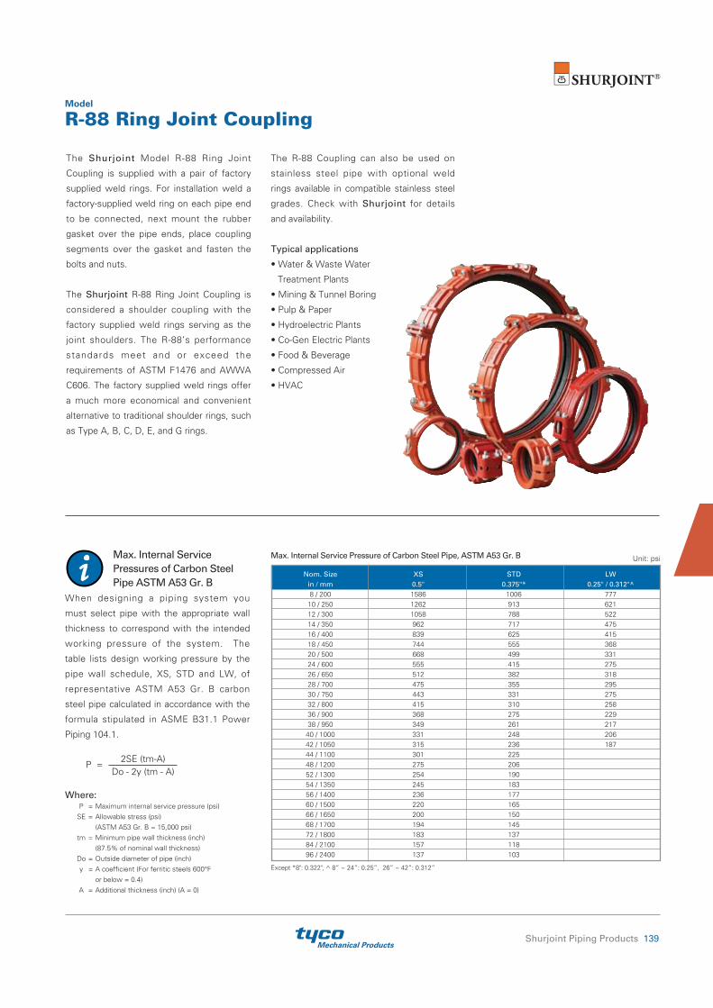
Mechanical ProductsShurjoint Piping Products 139
Model
R-88 Ring Joint Coupling
Max. Internal Service Pressures of Carbon Steel Pipe ASTM A53 Gr. B
When designing a piping system you
must select pipe with the appropriate wall
thickness to correspond with the intended
working pressure of the system. The
table lists design working pressure by the
pipe wall schedule, XS, STD and LW, of
representative ASTM A53 Gr. B carbon
steel pipe calculated in accordance with the
formula stipulated in ASME B31.1 Power
Piping 104.1.
2SE (tm-A)
P =
Do - 2y (tm - A)
Where: P = Maximum internal service pressure (psi) SE = Allowable stress (psi) (ASTM A53 Gr. B = 15,000 psi) tm = Minimum pipe wall thickness (inch) (87.5% of nominal wall thickness) Do = Outside diameter of pipe (inch) y = A coefficient (For ferritic steels 600°F or below = 0.4) A = Additional thickness (inch) (A = 0)
Nom. Size XS STD LW in / mm 0.5" 0.375"* 0.25" / 0.312"^ 8 / 200 1586 1006 777 10 / 250 1262 913 621 12 / 300 1058 788 522 14 / 350 962 717 475 16 / 400 839 625 415 18 / 450 744 555 368 20 / 500 668 499 331 24 / 600 555 415 275 26 / 650 512 382 318 28 / 700 475 355 295 30 / 750 443 331 275 32 / 800 415 310 258 36 / 900 368 275 229 38 / 950 349 261 217 40 / 1000 331 248 206 42 / 1050 315 236 187 44 / 1100 301 225 48 / 1200 275 206 52 / 1300 254 190 54 / 1350 245 183 56 / 1400 236 177 60 / 1500 220 165 66 / 1650 200 150 68 / 1700 194 145 72 / 1800 183 137 84 / 2100 157 118 96 / 2400 137 103
Max. Internal Service Pressure of Carbon Steel Pipe, ASTM A53 Gr. B Unit: psi
Except *8": 0.322", ^ 8” ~ 24”: 0.25”, 26” ~ 42”: 0.312”
The Shurjoint Model R-88 Ring Joint
Coupling is supplied with a pair of factory
supplied weld rings. For installation weld a
factory-supplied weld ring on each pipe end
to be connected, next mount the rubber
gasket over the pipe ends, place coupling
segments over the gasket and fasten the
bolts and nuts.
The Shurjoint R-88 Ring Joint Coupling is
considered a shoulder coupling with the
factory supplied weld rings serving as the
joint shoulders. The R-88’s performance
standards meet and or exceed the
requirements of ASTM F1476 and AWWA
C606. The factory supplied weld rings offer
a much more economical and convenient
alternative to traditional shoulder rings, such
as Type A, B, C, D, E, and G rings.
The R-88 Coupling can also be used on
stainless steel pipe with optional weld
rings available in compatible stainless steel
grades. Check with Shurjoint for details
and availability.
Typical applications
• Water & Waste Water
Treatment Plants
• Mining & Tunnel Boring
• Pulp & Paper
• Hydroelectric Plants
• Co-Gen Electric Plants
• Food & Beverage
• Compressed Air
• HVAC

Mechanical Products140 Shurjoint Piping Products
R-88Size: 12"
The Shurjoint Model R-88 Ring Joint
Coupling is an ideal pipe joining method
when pipe is difficult to groove or when
grooving is not the preferred joining method.
Available in sizes 8" to 96" the R-88 offers
ease of use and excellent performance.
Model
R-88 Ring Joint Coupling
Ring Clamp
8”~ 12”
B
A
C
O.D.R
E
L
1) Dimensions are subject to change without notice. Other sizes are available on request.* Working Pressure is based on rings both sides fully welded standard wall carbon steel pipe.# Working Pressure and End Load are the total from all internal and external loads based on the applicable pipe wall thickness.† Allowable Axial Displacement and Angular Movement (Deflection) figures shown are the maximum nominal range of movement at each R-88 coupling joint when rings are welded in the standard position. For
design and installation purposes these figures should be reduced by 25%.‡ The number of ring clamps listed is the minimum required to correctly position the weld ring around the circumference of the pipe end.
Rings both sides fully welded* Max. Max. Angular Nominal Pipe Working End Axial Movement / Dimensions Bolts Sealing Ring No. Size O.D. Pressure Load Displace- Deflection † Surface Size of Weight (CWP)# (CWP)# ment † Clamps‡ E Per Cplg Per Pipe A B C No. Size L R in in PSI Lbs in
Deg.(°) in / ft in in in in in in Lbs
mm mm Bar kN mm mm / m mm mm mm mm mm mm Kgs 8 8.625 400 23350 0-0.340
2.14 0.45 10.08 13.00 3.11
2 ¾ x 4¾ 0.91 ¼
3 16.8
200 219.1 28 105.51 0-8.7 37 256 330 79 M20x120 23 6.0 7.6 10 10.750 400 36280 0-0.340
1.95 0.41 12.29 15.20 3.25
2 ¾ x 4¾ 0.91 ¼
3 22.2
250 273.0 28 163.81 0-8.7 34 312 386 83 M20 x 120 23 6.0 10.1 12 12.750 400 51040 0-0.190
0.82 0.17 14.72 17.90 3.39
2 ⅞ x 6½ 1.02 ₅/₁₆ 3 30.8
300 323.9 28 230.59 0-4.8 14 374 455 86 --- 26 8.0 14.0
200 JIS 8.516 400 22770 0-0.340
1.50 0.31 9.96 12.87 3.11
2 --- 0.91 ¼
3 17.6
216.3 28 102.83 0-8.7 26 253 327 79 M20 x 120 23 6.0 8.0
250 JIS 10.528 400 34800 0-0.340
1.50 0.31 12.05 14.96 3.25
2 --- 0.91 ¼
3 22.0
267.4 28 157.16 0-8.7 26 306 380 83 M20 x 120 23 6.0 10.0
300 JIS 12.539 400 49360 0-0.190
1.50 0.31 14.53 17.72 3.39
2 --- 1.02 ₅/₁₆ 3 32.6
318.5 28 222.97 0-4.8 26 369 450 86 M20 x 120 26 8.0 14.8

Mechanical ProductsShurjoint Piping Products 141
R-88NSize: 24"
The Shurjoint Model R-88N is a two
segment Ring Joint Coupling. Available in
sizes 14" to 26" (350 mm to 650 mm). The
two-segment style offers an easier and
faster installation.
Model
R-88N Ring Joint Coupling
1) Dimensions are subject to change without notice. Other sizes are available on request.* Working Pressure is based on rings both sides fully welded standard wall carbon steel pipe.# Working Pressure and End Load are the total from all internal and external loads based on the applicable pipe wall thickness.† Allowable Axial Displacement and Angular Movement (Deflection) figures shown are the maximum nominal range of movement at each R-88 coupling joint when rings are welded in the standard position. For
design and installation purposes these figures should be reduced by 25%.‡ The number of ring clamps listed is the minimum required to correctly position the weld ring around the circumference of the pipe end.
Ring Clamp
O.D.R
E
L
14”~ 26”
A
B C
Rings both sides fully welded* Max. Max. Angular Nominal Pipe Working End Axial Movement / Dimensions Bolts Sealing Ring No. Size O.D. Pressure Load Displace- Deflection † Surface Size of Weight (CWP)# (CWP)# ment † Clamps‡ E Per Cplg Per Pipe A B C No. Size L R in in PSI Lbs in
Deg.(°) in / ft in in in in in in Lbs
mm mm Bar kN mm mm / m mm mm mm mm mm mm Kgs 14 14.000 400 61540 0-0.250
1.20 0.25 15.93 19.40 3.65
2 ⅞ x 5½ 1.02 ₅/₁₆ 4
38.3 350 355.6 28 277.94 0-6.4 21 405 493 93 --- 26 8.0 17.4 16 16.000 400 80380 0-0.250
0.90 0.19 17.92 21.52 3.65
2 ⅞ x 5½ 1.02 ₅/₁₆ 4
35.0 400 406.4 28 363.02 0-6.4 16 455 547 93 --- 26 8.0 15.9 18 18.000 400 101730 0-0.375
1.20 0.25 20.37 24.17 4.23
2 1 x 5½ 1.18 ₅/₁₆ 4
50.6 450 457.2 28 459.45 0-9.5 21 517 614 107 --- 30 8.0 23.0 20 20.000 400 125600 0-0.375
1.08 0.23 22.46 25.99 4.35
2 1 x 5½ 1.18 ⅜
4 68.7
500 508.0 28 567.22 0-9.5 19 570 660 110 --- 30 9.5 31.2 24 24.000 400 180860 0-0.375
0.80 0.17 27.17 30.00 4.84
4 ⅞ x 6½ 1.18 ½
4 104.7
600 609.6 28 816.80 0-9.5 14 690 762 123 --- 30 12.7 47.5 26 26.000 300 159190 0-0.500
1.06 0.22 29.58 32.78 6.69
4 1 x 8⅞ 1.97 ½
4 173.5
650 660.4 20 684.72 0-12.7 18 751 832 170 --- 50 12.7 78.7

Mechanical Products142 Shurjoint Piping Products
R-88Size: 48"
The Shurjoint Model R-88 Ring Joint
Coupling is available in sizes 28" to 96"
(700 mm to 2400 mm). The larger diameter
couplings are comprised of 4 to 8 housing
segments depending on the size and feature
two bolts at each joint segment to ensure a
positive connection.
Model
R-88 Ring Joint CouplingLarge diameter
Rings both sides fully welded* Max. Max. Angular Nominal Pipe Working End Axial Movement / Dimensions Bolts Sealing Ring No. Size O.D. Pressure Load Displace- Deflection † Surface Size of Weight (CWP)# (CWP)# ment † Clamps‡ E Per Cplg Per Pipe A B C No. Size L R in in PSI Lbs in
Deg.(°) in / ft in in in
in in in Lbs
mm mm Bar kN mm mm / m mm mm mm mm mm Kgs 28** 28.0 300 184630 0-0.500
0.90 0.19 31.75 35.47 6.69
12 ⅞ x 4 2.00 ½
4 222.2
700 711.2 20 794.11 0-12.7 16 806 901 170 50 12.7 101.0 30 30.0 300 211950 0-0.500
0.86 0.18 33.75 37.60 6.69
12
1 x 3½ 2.00 ½
4 218.9
750 762.0 20 911.61 0-12.7 15 857 955 170 50 12.7 99.5 32 32.0 300 241150 0-0.500
0.84 0.18 35.75 39.45 6.69
12
1 x 3½ 2.00 ½
4 225.4
800 812.8 20 1037.21 0-12.7 15 908 1002 170 50 12.7 102.2 34** 34.0 300 272230 0-0.500
0.84 0.18 37.75 41.50 7.87
12
1 x 3½ 2.00 ½
4 253.0
850 863.4 20 1170.37 0-12.7 15 959 1054 200 50 12.7 115.0 36 36.0 300 305200 0-0.500
0.76 0.16 39.75 43.50 7.87
12
1 x 3½ 2.00 ½
4 246.0
900 914.4 20 1312.72 0-12.7 13 1010 1103 200 50 12.7 111.6 38** 38.0 232 262980 0-0.500
0.76 0.16 41.75 45.50 7.87
12
1 x 3½ 2.00 ½
4 275.0
950 965.2 16 1170.10 0-12.7 13 1060 1156 200 50 12.7 125.0 40 40.0 232 291390 0-0.625
0.80 0.17 44.69 48.39 7.87
16
1 x 3½ 2.37 ⅝
6 310.2
1000 1016.0 16 1296.51 0-15.9 14 1135 1229 200 60 15.9 141.0 42** 42.0 232 321250 0-0.625
0.86 0.18 46.70 50.71 7.87
16
1¼ x 5 2.37 ⅝
6 326.9
1050 1066.8 16 1429.41 0-15.9 15 1186 1288 200 60 15.9 148.6 44** 44.0 232 352580 0-0.625
0.80 0.17 48.66 52.64 7.87
16
1¼ x 5 2.37 ⅝
6 343.2
1100 1117.6 16 1568.78 0-15.9 14 1236 1337 200 60 15.9 156.0 48 48.0 232 419600 0-0.625
0.70 0.15 52.68 55.91 7.87
16
1 x 3½ 2.37 ⅝
6 466.7
1200 1219.2 16 1866.98 0-15.9 12 1338 1420 200 60 15.9 211.8
Continued on next page.
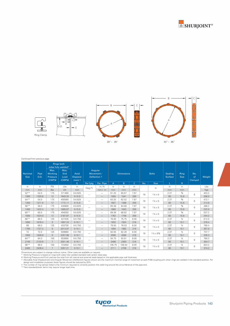
Mechanical ProductsShurjoint Piping Products 143
Dimensions are subject to change without notice. Other sizes are available on request. * Working Pressure is based on rings both sides fully welded standard wall carbon steel pipe.# Working Pressure and End Load are the total from all internal and external loads based on the applicable pipe wall thickness.† Allowable Axial Displacement and Angular Movement (Deflection) figures shown are the maximum nominal range of movement at each R-88 coupling joint when rings are welded in the standard position. For
design and installation purposes these figures should be reduced by 25%. ‡ The number of ring clamps listed is the minimum required to correctly position the weld ring around the circumference of the pipe end.** Non-standard/stock items may require longer lead time.
O.D.R
E
L
40”~ 96”28”~ 38”
B C
B C
AA
Ring Clamp
Continued from previous page.
Rings both sides fully welded* Max. Max. Angular Nominal Pipe Working End Axial Movement / Dimensions Bolts Sealing Ring No. Size O.D. Pressure Load Displace- Deflection † Surface Size of Weight (CWP)# (CWP)# ment † Clamps‡ E Per Cplg Per Pipe A B C No. Size L R in in PSI Lbs in
Deg.(°) in / ft in in in
in in in Lbs
mm mm Bar kN mm mm / m mm mm mm mm mm Kgs 52** 52.0 175 371460 0-0.625
--- --- 61.25 60.67 7.87
16
1¼ x 5 2.37 ⅝
6 453.2
1300 1320.8 12 1643.33 0-15.9 --- 1555 1541 200 60 15.9 206.0 54** 54.0 175 400580 0-0.625
--- --- 63.25 62.52 7.87
16
1¼ x 5 2.37 ⅝
6 472.1
1350 1371.6 12 1772.17 0-15.9 --- 1607 1588 200 60 15.9 214.6 56** 56.0 175 430800 0-0.625
--- --- 65.38 64.69 7.87
16
1¼ x 5 2.37 ⅝
6 488.2
1400 1422.4 12 1905.87 0-15.9 --- 1660 1643 200 60 15.9 222.0 60** 60.0 175 494550 0-0.625
--- --- 69.38 68.82 7.87
16
1¼ x 5 2.37 ⅝
6 537.2
1500 1524.0 12 2187.87 0-15.9 --- 1762 1748 200 60 15.9 244.2 66** 66.0 125 427430 0-0.750
--- --- 76.00 75.75 8.00
16
1½ x 5 2.37 ¾
8 612.5
1650 1676.4 9 1897.24 0-19.1 --- 1932 1924 216 60 19.1 278.4 68 68.0 125 453730 0-0.750
--- --- 78.50 78.03 8.00
16
1½ x 5 2.37 ¾
8 785.4
1700 1727.2 9 2013.97 0-19.1 --- 1994 1982 216 60 19.1 357.0 72 72.0 125 508680 0-0.750
--- --- 82.50 82.28 8.00
16
1½ x 6⅞ 2.37 ¾ 8 737.7
1800 1828.8 9 2257.88 0-19.1 --- 2095 2090 216 60 19.1 335.3 84** 84.0 100 553890 0-0.750
--- --- 94.75 93.81 8.00
16
1½ x 5 2.37 ¾
8 780.3
2100 2133.6 7 2501.46 0-19.1 --- 2406 2383 216 60 19.1 354.7 96** 96.0 100 723450 0-0.750
--- --- 106.75 106.54 8.00
16
1½ x 5 2.37 ¾
8 823.2
2400 2438.4 7 3267.21 0-19.1 --- 2711 2706 216 60 19.1 374.2

Mechanical Products144 Shurjoint Piping Products
Pipe O.D.
R
EL
B C
A
The Shurjoint Model RH-1000 coupling is a
high pressure ring joint coupling for use with
Sch. 40, Sch. 80 and heavier wall carbon
steel pipe.
The coupling is comprised of two ductile
Model
RH-1000 1000 PSI Ring Joint Coupling
iron heavy-wall housings, rubber gasket
(EPDM or Nitrile) and two heat-treated
track bolts and nuts which provide a fully
restrained joint and a maximum working
pressure of 1,000 psi (70 Bar) depending on
* Working pressure is based on standard wall carbon steel pipe. Burst test pressures are minimum 2 times the maximum working pressures. Bolt & nut are UNC threaded. **Non-standard/stock items may require longer lead time.
Nominal Pipe Max. Working Max. End Dimensions Bolt / Nut Pipe-end Preparation Size O.D. Pressure Load Deflection Weight (CWP)* (CWP) A B C No. Size R L E (max) in in PSI Lbs in in in
in Deg. in in in Lbs
mm mm Bar kN mm mm mm mm mm mm Kgs 8 8.625 1000 58390 11.10 14.65 3.86
2 1 x 5½ 0° – 18' 0.472 - 0.500 1 0.13 39.8
200 219.1 69 263.79 282 372 98 12.0 - 12.7 25 3.2 18.1 10** 10.750 1000 90710 13.32 16.93 4.25
2 1 x 6½ 0° – 38' 0.472 - 0.500 1 0.13 57.2
250 273 69 409.54 340 430 108 12.0 - 12.7 25 3.2 26.0 12** 12.750 1000 127610 16.33 20.07 4.17
2 1 x 6½ 0° – 32' 0.472 - 0.500 1 0.13 72.6
300 323.9 69 576.49 415 510 106 12.0 - 12.7 25 3.2 33.0
* Working pressure is based on API 5L X65 line pipe. Burst test pressures are minimum 2 times the maximum working pressures. Bolt & nut are UNC threaded. **Non-standard/stock items may require longer lead time.
Nominal Pipe Max. Working Max. End Dimensions Bolt / Nut Pipe-end Preparation Size O.D. Pressure Load Weight (CWP)* (CWP) A B C No. Size R L E (max) in in PSI Lbs in in in
in in in in Lbs
mm mm Bar kN mm mm mm mm mm mm Kgs 8 8.625 3000 175180 11.81 15.51 5.83
2
1⅛ x 5⅛ 0.472 ~ 0.500 1.22 ⅛ 78.92 200 219.1 207 791.36 300 394 148 12.0 ~ 12.7 31 3 35.87 10 10.748 3000 272040 14.96 18.93 5.98
4
1¼ x 6½ 0.625 ~ 0.629 1.22 ⅛ 116.36
250 273.0 207 1228.61 380 481 152 15.9 ~ 16.0 31 3 52.78 12** 12.752 3000 382950 18.50 22.48 6.81
4
1½ x 6¼ 0.625 ~ 0.629 1.22 ⅛ 212.27
300 323.9 207 1729.46 470 572 173 15.9 ~ 16.0 31 3 96.24
the pipe used.
Two steel weld rings are factory supplied
with the coupling. Steel rings must always
be fully welded on both sides.
The Shurjoint Model RX-3000 coupling is
a high pressure ring joint coupling for use
with Sch. 80, 120 and heavier wall carbon
steel pipe.
The coupling is comprised of two ductile
Model
RX-3000 3000 PSI Ring Joint Coupling
iron heavy-wall housings, rubber gasket
(EPDM or Nitrile) and four heat-treated
track bolts and nuts which provide a fully
restrained joint and a maximum working
pressure up to 3,000 psi (210 Bar)
depending on the pipe used.
Two steel weld rings are factory supplied
with the coupling. Steel rings must always
be fully welded on both sides.
Pipe O.D.
R
EL
B C
A

Mechanical ProductsShurjoint Piping Products 145
The Shurjoint Model RX-3770 Ring Joint
Coupling is designed to provide a fully
restrained joint for use with extra-strong
carbon steel pipe including API 5L Grade
Model
RX-3770 3770 PSI Ring Joint Coupling
X65 line pipe.
The coupling is comprised of two ductile
iron heavy-wall housing segments, rubber
gasket (EPDM) and four heat-treated track
* Working pressure is based on API 5L X65 line pipe. Burst test pressures are minimum 2 times the maximum working pressures. Bolt & nut are UNC threaded.
Nominal Pipe Max. Working Max. End Dimensions Bolt / Nut Pipe-end Preparation Size O.D. Pressure Load Weight (CWP)* (CWP) A B C No. Size R L E (max) in in PSI Lbs in in in
in in in in Lbs
mm mm Bar kN mm mm mm
mm mm mm Kgs 6 6.625 3770 129890 10.24 12.64 5.87
4 ⅞ x 6½ 0.472 1.22 0.20 61.2 150 168.3 260 578.11 260 321 149 12 31 5 27.7 8 8.625 3770 220150 12.95 16.30 6.89
4 1¼ x 6½ 0.625 1.50 0.20 110.0 200 219.1 260 979.78 329 414 175 16 38 5 49.9 10 10.750 3770 342000 15.90 19.84 7.72
4 1½ x 6⅞ 0.750 1.50 0.20 174.5 250 273.0 260 1521.14 404 504 196 19 38 5 79.2 12 12.750 3770 481090 19.00 23.10 8.63
4 1½ x 6⅞ 0.875 1.50 0.24 247.1 300 323.9 260 2141.24 482 587 219 22 38 6 112.3
bolts and nuts. Two steel weld rings are
factory supplied with a coupling. Steel rings
shall always be fully welded on both sides.
E
B C
A
LR

Mechanical Products146 Shurjoint Piping Products
Ring Joint Fittings
Shurjoint offers a full range of ring joint
fittings for use with Model R-88 ring joint
couplings.
• 8” - 16” (200 mm – 400 mm) Models
RJ-10, RJ-11 & RJ-60 and Model RJ-20
Model
RJ-10 90° Elbow RJ-11 45° ElbowRJ-20 Tee RJ-60 Cap
are available in cast ductile iron to ASTM
A536 Gr. 65-45-12.
• Larger sizes are made of carbon steel
standard weight pipe, ASTM A53 Gr. B
or equivalent, or fabricated from wrought
carbon steel of the equivalent properties.
• Other configurations are also available
upon request. Contact Shurjoint for
details.
Nominal Pipe RJ-10 90° Elbow RJ-11 45° Elbow RJ-20 Tee RJ-60 Cap Size O.D. C - E Weight C - E Weight C - E Weight E - E Weight in in in Lbs in Lbs in Lbs in Lbs mm mm mm Kgs mm Kgs mm Kgs mm Kgs 8 8.625 7.75 28.6 4.25 20.9 7.75 46.2 3.00 12.1 200 219.1 197 13.0 108 9.5 197 21.0 76 5.5 10 10.750 9.00 55.0 4.75 39.6 9.00 72.6 3.00 13.2 250 273.0 229 25.0 121 18.0 229 33.0 76 6.0 12 12.750 10.00 77.0 5.25 50.6 10.00 103.4 3.00 17.6 300 323.9 254 35.0 133 23.0 254 47.0 76 8.0
200 JIS 8.516 7.75 28.6 4.25 20.9 7.75 46.2 3.00 12.1
216.3 197 13.0 108 9.5 197 21.0 76 5.5
250 JIS 10.528 9.00 55.0 4.75 39.6 9.00 72.6 3.00 13.2
267.4 229 25.0 121 18.0 229 33.0 76 6.0
300 JIS 12.539 10.00 77.0 5.25 50.6 10.00 103.4 3.00 17.6
318.5 254 35.0 133 23.0 254 47.0 76 8.0 14 14.000 11.00 81.4 6.00 52.8 11.00 118.8 4.00 26.4 350 355.6 280 37.0 152 24.0 280 54.0 102 12.0 16 16.000 12.00 99.0 7.25 101.2 12.00 154.0 4.00 33.0 400 406.4 305 45.0 184 46.0 305 70.0 102 15.0 18 18.000 27.00 209.0 11.25 105.6 15.50 268.0 5.00 46.2 450 457.2 686 95.0 286 48.0 394 122.0 127 21.0 20 20.000 30.00 203.6 12.50 110.0 17.25 337.0 6.00 57.2 500 508.0 762 138.0 318 50.0 438 153.0 152 26.0 24 24.000 36.00 485.0 15.00 176.0 20.00 466.0 6.00 77.0 600 609.6 914 220.0 381 80.0 508 212.0 152 35.0 26 26.000 39.00 521.0 16.00 262.0 22.50 766.0 10.50 110.0 650 660.4 991 237.0 406 119.0 572 348.0 267 50.0 28 28.000 42.00 605.0 17.25 304.0 23.50 862.0 10.50 123.0 700 711.2 1067 275.0 438 138.0 597 392.0 267 56.0 30 30.000 45.00 695.0 18.50 348.0 25.00 992.0 10.50 136.0 750 76.20 1143 316.0 480 158.0 635 451.0 267 62.0 32 32.000 48.00 792.0 19.75 396.0 26.50 1135.0 10.50 248.6 800 812.8 1219 360.0 502 180.0 673 516.0 267 113.0 34 34.000 51.00 895.0 21.00 449.0 28.00 1285.0 10.50 165.0 850 863.4 1295 407.0 533 204.0 711 584.0 267 75.0 36 36.000 54.00 1005.0 22.25 504.0 30.00 1445.0 10.50 334.4 900 914.4 1372 457.0 565 229.0 762 657.0 267 152.0 40 40.000 60.00 1241.0 24.88 620.0 33.00 1790.0 12.00 224.0 1000 1016.0 1524 564.0 632 282.0 838 814.0 305 102.0 42 42.000 63.00 1368.0 26.00 684.0 35.00 1841.0 12.00 242.0 1050 1066.8 1600 622.0 660 311.0 889 837.0 305 110.0 44 44.000 66.00 1503.0 27.39 752.0 36.00 2075.0 13.50 277.0 1100 1117.6 1676 683.0 696 342.0 914 943.0 343 126.0 48 48.000 72.00 1790.0 29.88 895.0 40.00 2488.0 13.50 315.0 1200 1219.2 1829 814.0 759 407.0 1016 1131.0 343 143.0
• C-E of RJ-10 and RJ-11 18” and larger sizes and E-E of RJ-60 26” and larger sizes conform to ANSI B16.9. All other sizes are to manufacturer's standard.
RJ-20RJ-11RJ-10 RJ-60
C-E
C-E C
-E
C-E
E-E
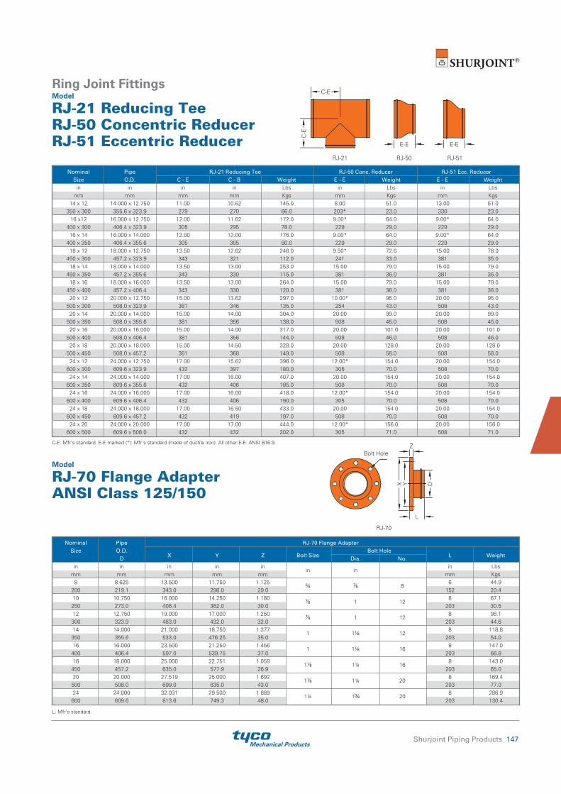
Mechanical ProductsShurjoint Piping Products 147
Ring Joint FittingsModel
RJ-21 Reducing TeeRJ-50 Concentric ReducerRJ-51 Eccentric Reducer
Nominal Pipe RJ-21 Reducing Tee RJ-50 Conc. Reducer RJ-51 Ecc. Reducer Size O.D. C - E C - B Weight E - E Weight E - E Weight in in in in Lbs in Lbs in Lbs mm mm mm mm Kgs mm Kgs mm Kgs 14 x 12 14.000 x 12.750 11.00 10.62 145.0 8.00 51.0 13.00 51.0 350 x 300 355.6 x 323.9 279 270 66.0 203* 23.0 330 23.0 16 x12 16.000 x 12.750 12.00 11.62 172.0 9.00* 64.0 9.00* 64.0 400 x 300 406.4 x 323.9 305 295 78.0 229 29.0 229 29.0 16 x 14 16.000 x 14.000 12.00 12.00 176.0 9.00* 64.0 9.00* 64.0 400 x 350 406.4 x 355.6 305 305 80.0 229 29.0 229 29.0 18 x 12 18.000 x 12.750 13.50 12.62 246.0 9.50* 72.6 15.00 78.0 450 x 300 457.2 x 323.9 343 321 112.0 241 33.0 381 35.0 18 x 14 18.000 x 14.000 13.50 13.00 253.0 15.00 79.0 15.00 79.0 450 x 350 457.2 x 355.6 343 330 115.0 381 36.0 381 36.0 18 x 16 18.000 x 16.000 13.50 13.00 264.0 15.00 79.0 15.00 79.0 450 x 400 457.2 x 406.4 343 330 120.0 381 36.0 381 36.0 20 x 12 20.000 x 12.750 15.00 13.62 297.0 10.00* 95.0 20.00 95.0 500 x 300 508.0 x 323.9 381 346 135.0 254 43.0 508 43.0 20 x 14 20.000 x 14.000 15.00 14.00 304.0 20.00 99.0 20.00 99.0 500 x 350 508.0 x 355.6 381 356 138.0 508 45.0 508 45.0 20 x 16 20.000 x 16.000 15.00 14.00 317.0 20.00 101.0 20.00 101.0 500 x 400 508.0 x 406.4 381 356 144.0 508 46.0 508 46.0 20 x 18 20.000 x 18.000 15.00 14.50 328.0 20.00 128.0 20.00 128.0 500 x 450 508.0 x 457.2 381 368 149.0 508 58.0 508 58.0 24 x 12 24.000 x 12.750 17.00 15.62 396.0 12.00* 154.0 20.00 154.0 600 x 300 609.6 x 323.9 432 397 180.0 305 70.0 508 70.0 24 x 14 24.000 x 14.000 17.00 16.00 407.0 20.00 154.0 20.00 154.0 600 x 350 609.6 x 355.6 432 406 185.0 508 70.0 508 70.0 24 x 16 24.000 x 16.000 17.00 16.00 418.0 12.00* 154.0 20.00 154.0 600 x 400 609.6 x 406.4 432 406 190.0 305 70.0 508 70.0 24 x 18 24.000 x 18.000 17.00 16.50 433.0 20.00 154.0 20.00 154.0 600 x 450 609.6 x 457.2 432 419 197.0 508 70.0 508 70.0 24 x 20 24.000 x 20.000 17.00 17.00 444.0 12.00* 156.0 20.00 156.0 600 x 500 609.6 x 508.0 432 432 202.0 305 71.0 508 71.0
C-E: Mfr's standard. E-E marked (*): Mfr's standard (made of ductile iron). All other E-E: ANSI B16.9.
Model
RJ-70 Flange AdapterANSI Class 125/150
RJ-21 RJ-50 RJ-51
C-E
C-E
E-EE-E
L: Mfr's standard.
Nominal Pipe RJ-70 Flange Adapter Size O.D.
X Y Z Bolt Size Bolt Hole
L Weight D Dia. No. in in in in in
in in in Lbs
mm mm mm mm mm mm Kgs 8 8.625 13.500 11.750 1.125 ¾ ⅞ 8
6 44.9 200 219.1 343.0 298.0 29.0 152 20.4 10 10.750 16.000 14.250 1.180 ⅞ 1 12
8 67.1 250 273.0 406.4 362.0 30.0 203 30.5 12 12.750 19.000 17.000 1.250 ⅞ 1 12
8 98.1 300 323.9 483.0 432.0 32.0 203 44.6 14 14.000 21.000 18.750 1.377
1 1⅛ 12 8 118.8
350 355.6 533.0 476.25 35.0 203 54.0 16 16.000 23.500 21.250 1.456
1 1⅛ 16 8 147.0
400 406.4 597.0 539.75 37.0 203 66.8 18 18.000 25.000 22.751 1.059
1⅛ 1¼ 16 8 143.0
450 457.2 635.0 577.9 26.9 203 65.0 20 20.000 27.519 25.000 1.692
1⅛ 1¼ 20 8 169.4
500 508.0 699.0 635.0 43.0 203 77.0 24 24.000 32.031 29.500 1.889
1¼ 1⅜ 20 8 286.9
600 609.6 813.6 749.3 48.0 203 130.4
RJ-70
L
Z
DYX
Bolt Hole

Mechanical Products148 Shurjoint Piping Products
The following tables show maximum cold
working pressures (CWP) of Shurjoint R-88
couplings based on rings both sides fully
Pressure Performance Data
welded and corresponding working pressure
for applicable steel pipe.
Nominal Pipe Max. Working Pressure / Max. End Load Rings both sides fully welded Size O.D. XS (.500”) STD (.375”) LW (.312”) in in PSI Lbs PSI Lbs PSI Lbs mm mm Bar kN Bar kN Bar kN 8 8.625 600 35040 400 23359 400 23359 200 219.1 42 150.74 28 105.51 28 105.51 10 10.750 600 54430 400 36287 400 36287 250 273.0 42 234.02 28 163.81 28 163.81 12 12.750 600 76567 400 51045 400 51045 300 323.9 42 329.42 28 230.59 28 230.59
200 JIS 8.516 600 34215 400 22772 400 22772
216.3 42 150.58 28 102.83 28 102.83
250 JIS 10.528 600 52205 400 34803 400 34803
267.4 42 224.52 28 157.16 28 157.16
300 JIS 12.539 600 74054 400 49369 400 49369
318.5 42 318.53 28 222.97 28 222.97 14 14.000 600 92316 400 61544 350 53851 350 (R-88N) 355.6 42 397.06 28 277.94 24 238.23 16 16.000 500 100480 400 80384 350 70336 400 (R-88N) 406.4 35 453.78 28 363.02 24 311.16 18 18.000 500 12170 400 101736 350 89019 450 (R-88N) 457.2 35 574.31 28 459.45 24 393.82 20 20.000 500 157000 400 125600 300 94200 500(R-88N) 508.0 35 709.03 28 567.22 20 405.16 24 24.000 500 226080 400 180864 250 113040 600 (R-88N) 609.6 35 1021.00 28 816.80 17 495.92 26 26.000 400 212264 300 159198 250 132665 650 (R-88N) 660.4 28 958.61 20 584.72 17 582.01 28 28.000 400 246176 300 184632 250 153860 700 711.2 28 1111.76 20 794.11 17 675.00 30 30.000 400 282600 300 211950 250 176625 750 762.0 28 1276.26 20 911.61 17 774.87 32 32.000 400 321536 300 241152 250 200960 800 812.8 28 1452.10 20 1037.21 17 881.63 34 34.000 350 317611 300 272238 200 181492 850 863.4 24 1404.45 20 1170.37 14 819.26 36 36.000 350 356076 300 305208 200 203472 900 914.4 24 1575.26 20 1312.72 14 918.90 38 38.000 300 340062 232 262981 175 198370 950 965.2 20 1462.63 16 1170.10 12 877.58 40 40.000 300 376800 232 291392 175 219800 1000 1016.0 20 1620.64 16 1296.51 12 972.39 42 42.000 300 415422 232 321260 175 242330 1050 1066.8 20 1786.76 16 1429.41 12 1072.05 44 44.000 300 455928 232 352584 175 265958 1100 1117.6 20 1960.98 16 1568.78 12 1176.59 48 48.000 300 542592 232 419604 --- --- 1200 1219.2 20 2333.72 16 1866.98 --- --- 52 52.000 232 492452 175 371462 --- --- 1300 1320.8 16 2191.11 12 1643.33 --- --- 54 54.000 232 531062 175 400586 --- --- 1350 1371.6 16 2362.90 12 1772.17 --- --- 56 56.000 232 571128 175 430808 --- --- 1400 1422.4 16 2541.17 12 1905.87 --- --- 60 60.000 232 656532 175 494550 --- --- 1500 1524.0 16 2917.16 12 2187.87 --- --- 66 66.000 175 598406 125 427433 --- --- 1650 1676.4 12 2647.32 9 1897.24 --- --- 68 68.000 175 635222 125 453730 --- --- 1700 1727.2 12 2810.19 9 2013.97 --- --- 72 72.000 150 610416 125 508680 --- --- 1800 1828.8 10 2625.44 9 2257.88 --- --- 84 84.000 125 692370 100 553896 --- --- 2100 2133.6 9 3073.22 7 2501.46 --- --- 96 96.000 125 904320 100 723456 --- --- 2400 2438.4 9 4014.01 7 3267.21 --- ---
Model R-88 Ring Joint Coupling

Mechanical ProductsShurjoint Piping Products 149
Shurjoint Shouldered Piping System
The Shurjoint shouldered piping system is
a classic and versatile piping method used
for a wide range of applications including
irrigation, dewatering on construction sites,
and other installations, etc. The shouldered
system features full flow characteristics,
provides speed and ease of installation,
and proven reliability. The system provides
for limited expansion and contraction and
accommodates some linear and angular
movement. Each joint is a union.
The Shurjoint shouldered piping system
utilizes Type A weld-on rings, manufactured
from mild steel or material compatible to
pipe end used.
Type A Weld-on RingHousing Segment
Gasket
Bolt & Nut
Shoulder Dimensions( Type A Weld-on Rings )
The Shurjoint shouldered piping system
utilizes Type A weld-on rings, manufactured
from mild steel or material compatible to
pipe end used. Type A rings are suitable
for services up to maximum 600 psi
(40 Bar) for sizes up to 4" (100 mm) and
400 psi (28 Bar) for 5" (125 mm) through
8" (200 mm). Nominal Pipe O.D. Shoulder Dia. Shoulder Length Nominal Gap Size D1 D2 L E in in in in in mm mm mm mm mm 2 2.375 2.618 0.625 0.125 50 60.3 66.5 16.0 3.2 3 3.500 3.819 0.625 0.125 80 88.9 97.0 16.0 3.2 4 4.500 4.803 0.688 0.125 100 114.3 122.0 17.5 3.2
165.1 mm 6.500 6.870 0.688 0.125
165.1 174.5 17.5 3.2 6 6.625 7.007 0.688 0.125 150 168.3 178.0 17.5 3.2 8 8.625 9.134 0.813 0.125 200 219.1 232.0 20.6 3.2 10 10.750 11.260 0.813 0.125 250 273.0 286.0 20.6 3.2 12 12.750 13.248 0.813 0.125 300 323.9 336.5 20.6 3.2
Note: The exterior surface and the edge of the shouldered pipe ends must be free from any indentations, projections or other harmful surface defects such as weld splatters, any lumps of galvanizing, rust, dirt and score marks. Shouldered rings must be contacted or near tight to the pipe. The “stand off length* ” must be accurately consistent in the circumference.( *:The distance between the edge of the Shouldered ring and the pipe end (⅓ the shoulder length ‘L’ ).
L E
L3
øD2
øD1

Mechanical Products150 Shurjoint Piping Products
The Shurjoint Model S35 coupling is a
flexible type shouldered coupling for general
applications for use on Type A shouldered
pipe ends. The housing segments are made
of ductile iron to ASTM A536 Gr. 65-45-12
and or A395 Gr. 65-45-15 and are normally
supplied in hot-dip galvanized. The standard
rubber gasket is Grade T Nitrile.
Model
S35 Shouldered Flexible Coupling
Model
SD-28A Shouldered Toggle Coupling
The Shurjoint Model SD-28A coupling is
designed to connect shouldered-end pipe
with Type A rings for services where
frequent assembly and disassembly is
desired or required. The housing segments
are hinged with a lever handle for easy
installation. The use of a split pin prevents
accidental opening of the couplings. The
housing segments are made of
ductile iron to ASTM A536 Gr.
65-45-12 and or A395 Gr. 65-45-
15 and are normally supplied in
hot-dip galvanized. The standard
rubber gasket is Grade T Nitrile.
Dimensions
Allowable Nominal Pipe Working Pipe Bolt Size O.D. Pressure End Deflection Size Weight (CWP)* A B C Separation in in PSI in in in in
Deg. (°) in Lbs
mm mm Bar mm mm mm mm Kgs 2 2.375 600 3.90 5.47 1.81 0.13
2° 43' ⅜" x 2⅛" 2.4
50 60.3 40 99.0 139.0 46.0 3.2 1.1 3 3.500 600 5.08 6.61 1.81 0.13
1° 53' ½" x 3" 3.3
80 88.9 40 129.0 168.0 46.0 3.2 1.5 4 4.500 600 6.26 7.87 1.97 0.13
1° 29' ½" x 3" 4.9
100 114.3 40 159.0 200.0 50.0 3.2 2.2
165.1 mm 6.500 600 8.39 10.50 1.97 0.13
1° 2' ⅝" x 3½" 7.7
165.1 40 213.0 267.0 50.0 3.2 3.5 6* 6.625 600 8.62 11.00 1.97 0.13
1° 1' ⅝" x 3½" 8.4
150 168.3 40 219.0 279.0 50.0 3.2 3.8 8 8.625 600 10.75 13.19 2.36 0.13
0° 47' ¾" x 4¾" 13.0
200 219.1 40 273.0 335.0 60.0 3.2 5.9 10* 10.750 300 13.20 15.62 2.56 0.13
0° 47' ¾" x 4¾" 19.8
250 273.0 20 335.4 396.8 65.0 3.2 9.0 12* 12.750 300 15.19 17.72 2.56 0.13
0° 47' ¾" x 4¾" 22.9
300 323.9 20 385.8 450.1 65.0 3.2 10.4
* Non-standard/stock items may require longer lead time.
Dimensions
Allowable Nominal Pipe Working Pipe Size O.D. Pressure End Deflection Weight (CWP)** A B C Separation in in PSI in in in in
Deg. (°) Lbs
mm mm Bar mm mm mm mm Kgs 2* 2.375 400 39.32 4.43 1.93 0.125
2º - 43' 2.8
50 60.3 28 86.5 112.5 49 3.2 1.3 3* 3.500 400 4.96 6.46 1.93 0.125
1º - 53' 4.4
80 88.9 28 126.0 164.0 49 3.2 2.0 4 4.500 400 6.30 8.43 2.05 0.125
1º - 29' 6.6
100 114.3 28 160.0 214.0 52 3.2 3.0 6* 6.500 400 8.43 11.14 2.05 0.125
1º - 2' 6.5
150 165.1 28 214.0 283.0 52 3.2 4.3 6 6.625 400 8.54 11.10 2.05 0. 125
1º - 1' 9.9
150 168.3 28 217.0 282.0 52 3.2 4.5 8* 8.625 400 10.95 14.17 2.36 0.125
0º - 47' 18.3
200 219.1 28 278.0 360.0 60 3.2 8.3
* Non-standard/stock items may require longer lead time.** Working pressure is based on standard wall carbon steel pipe.
B C
A
B C
A

Mechanical ProductsShurjoint Piping Products 151
The Shurjoint Model 79 Wildcat Coupling
is designed to mechanically join plain-
end or beveled end carbon steel pipe.
The Wildcat couplings can be used for a
variety of applications including mining,
process piping, manifold piping and oilfield
services. The Wildcat couplings feature
case-hardened jaws* within the housings
and large diameter heat treated track bolts
that when tightened securely grip the pipe
surface. As with grooved couplings, a
C-shaped rubber gasket effectively seals the
pipe ends (* For sizes larger than 14” (350 mm) ,
jaws are made of 17-4PH stainless steel.)
The Shurjoint Wi ldcat coupl ing is
recommended for use on steel pipe
with a hardness less than HB 150, not
recommended for plastic, HDPE, cast iron or
other brittle pipe.
Gaskets are available either in Grade
E EPDM for water services of -29°F to +
230°F (-34°C to + 110°C) or Grade T Nitrile
for oil services -20°F to +180°F (-29°C to
+82°C).
Gasket
Housing Segment
Bolt / Nut
Hardened Steel Jaws
Steel Pipe 2" – 16"(Hardness HB 150 max.)
Plain-End Piping System for Steel PipeModel
79 Wildcat Coupling
Bolts and nuts must always be
tightened to the required torque.
Nominal Pipe Max. Working Max. Required Bolt Dimensions Size O.D. Pressure* End Load Bolt Torque No. Size A B C Weight in in PSI Lbs Lbs-Ft
in in in in Lbs
mm mm Bar kN Nm mm mm mm Kgs 1 1.315 750 1020 150
2 ½ x 2⅜ 2.60 4.37 3.05 3.3 25 33.4 52 4.55 200 66 111 78 1.5 1½ 1.900 750 2130 150
2 ½ x 2⅜ 3.15 5.08 3.05 3.9 40 48.3 52 9.52 200 80 129 78 1.8 2 2.375 750 3320 150
2 ⅝ x 3½ 3.75 5.94 3.54 7.0
50 60.3 52 14.84 200 95 151 90 3.2 2½ 2.875 600 3890 150
2 ⅝ x 3½ 4.25 6.46 3.54 7.3
65 73.0 42 17.57 200 108 164 90 3.3 3 3.500 600 5770 200
2 ¾ x 4¾ 5.00 7.48 3.54 11.0
80 88.9 42 26.06 270 127 190 90 5.0 4 4.500 450 7150 200
2 ¾ x 4¾ 6.14 8.78 4.00 14.3
100 114.3 31 32.82 270 154 223 102 6.5 5 5.563 300 7290 250
2 ⅞ x 6½ 7.36 10.31 4.38 24.2
125 141.3 20 32.91 340 187 262 111 11.0 6 6.625 300 10340 250
2 ⅞ x 6½ 8.50 11.50 4.38 28.6
150 168.3 20 46.69 340 216 292 111 13.0 8 8.625 250 14600 200
4 ¾ x 4¾ 10.88 14.02 5.00 41.8
200 219.1 17 64.06 270 276 356 127 19.0 10 10.750 250 22680 300
4 ⅞ x 6½ 12.60 16.14 5.00 52.8
250 273.0 17 99.46 400 320 410 127 24.0 12 12.750 250 31900 350
4 1 x 6½ 14.60 18.54 5.00 63.1
300 323.9 17 140.00 470 371 471 127 28.7 14 14.000 200 30770 350
4 1 x 6½ 16.70 20.00 5.28 93.5
350 355.6 14 138.97 470 424 508 134 42.5 16 16.000 150 30140 350
4 1 x 6½ 18.70 22.00 5.28 95.7
400 406.4 10 129.65 470 475 559 134 43.5
* Working pressure is for plain-end standard wall steel pipe with hardness less than HB150.
B C
A

Mechanical Products152 Shurjoint Piping Products
Notes

Mechanical ProductsShurjoint Piping Products 153
Notes

Mechanical Products154 Shurjoint Piping Products
Notes

Mechanical ProductsShurjoint Piping Products 155
HDPE Series ........................................................................................... 156
H305 HDPE Coupling ........................................................................ 157
H307 HDPE Transition Coupling ........................................................ 158
H312 HDPE Flange Adapter .............................................................. 159
Section 7
HDPE Series

Mechanical Products156 Shurjoint Piping Products
HDPE Series
Shurjoint offers a series HDPE couplings and adapters for joining HDPE pipe. The use of HDPE (high density polyethylene) pipe continues to grow in popularity as its benefits over traditional materials are realized in a variety of service applications. The benefits of an HDPE pipe system include a longer service life, increased flexibility, reduced weight, increased resistance to corrosion, chemicals, and fatigue, as well as superior flow characteristics. HDPE is now commonly used in service applications including municipal water and waste water, water distribution and transport, mining, slurry and many other general and industrial applications.
Shurjoint HDPE couplings provide a fast and
easy way to mechanically join HDPE pipe.
A series of sharply machined teeth securely
grip the pipe as the bolts are tightened,
resulting in a leak-free joint. The Shurjoint
joining method eliminates the need for costly
heat fusion equipment. The highly restrained
joint allows long lengths of pipe to be pulled
from one area to another. With the removal
of a few bolts one can easily access the
system for cleaning, maintenance, changes
and or system expansion.
Shurjoint HDPE couplings are designed
to join IPS HDPE pipe, DR32.5 to 7.3,
conforming to ASTM D2513, D3350 and or
ANSI/AWWA C901 and ISO HDPE pipe, SDR
9 to 26, conforming to ISO 4427-1/2.
Marking: Use a marker and measur ing tape to p lace “Gasket Centering Marks” and “Coupling Centering Marks” on each pipe end per the installation instructions.
Install Gasket: Place a gasket over the pipe ends and center the gasket in between the first set gasket centering marks. The pipe ends should always be butted against each other.
Mount Housings: Place the housings over the gasket, ensure the gasket s tays centered between the first set marks made on the pipe ends and the housings are properly centered between the second set coupling center marks. Also make sure that housing tongue and groove (T&G) mate correctly.
Tighten Nuts: Tighten nuts alternately and equally until the bolt pads meet and make metal-to-metal contact. Repeated alternate tightening will reduce tightening torque considerably. Tighten nuts by another one quarter to one half turn to make sure the bolts and nuts are snug and secure.
How to install
Pipe Dimension PE4710 PE3608 Ratio (DR) PE100 PE3408 DR 7.3 317 265 DR 9 250 200 DR 11 200 160 DR 13.5 160 130 DR 17 125 100 DR 21 100 80 DR 26 80 65 DR 32.5 63 50
Pressure Ratings (psi) - IPS Size
Design stress: PE4710 1000 psi, PE3608 & 3408 800 psi
DR (Pipe Dimension Ratio)Where:
D = pipe outside diameter, in t = pipe minimum wall thickness, in
DR =Dt
Pipe Dimension Ratio (SDR) PE100 PE80 SDR 9 20 16 SDR 11 16 10 SDR 17 10 6.3 SDR 26 6.3 4
Pressure Ratings (Bar) - ISO Size
Design Stress: PE100 8.0 MPa, PE80 5.0 MPa
SDR (Standard Dimension Ratio)Where:
D = pipe outside diameter, mm t = pipe minimum wall thickness, mm
SDR =Dt
As the ductile iron coupling is much stronger
than HDPE pipe itself, pressure ratings of
HDPE couplings are determined by the
pressure rating of HDPE pipe used. Pressure
ratings of HDPE pipe vary depending on DR
or SDR (standard dimension ratio) and design
stress of the material.
Refer to the Shurjoint installation instruction manual for complete instructions. Shurjoint HDPE couplings are not intended for use on PVC, PP or other materials. Do not use standard soap based lubricant on HDPE pipe. Shurjoint recommends the use of a silicone based lubricant with the HDPE series. In order to avoid injuries from the sharp machined teeth, wear gloves when handling.

Mechanical ProductsShurjoint Piping Products 157
The Shurjoint Model H305 HDPE Couplings
feature four bolt housings and a series of
sharply machined teeth which securely grip
the pipe as the bolts and nuts are tightened.
The result is a leak-tight joint that is as strong
as or stronger than the pipe itself. The H305
also features a contoured housing with
integral ramps along the outside diameter to
help the coupling slide over most obstacles
during the relocation of pipe runs.
Nominal Pipe Dimensions Bolt Size O.D. A B C No. Size Weight in in in in in
in Lbs
mm mm mm mm mm Kgs 2 2.375 3.39 5.24 4.57
4 ½ x 2⅜ 5.7 50 60.3 86 133 116 2.6 3 3.500 4.61 6.50 4.57
4 ½ x 3 7.9
80 88.9 117 165 116 3.6 4 4.500 5.75 7.95 5.75
4 ½ x 3 11.4
100 114.3 146 202 146 5.2 5 5.563 6.66 8.25 4.63
4 ½ x 3 9.9
125 141.3 169 210 118 4.5 6 6.625 7.87 10.75 5.87
4 ⅝ x 3½ 18.0
150 168.3 200 273 149 8.2 8 8.625 10.39 13.11 6.02
4 ⅝ x 3½ 28.4
200 219.1 264 333 153 12.9 10 10.750 12.52 15.71 6.50
4 ¾ x 4¾ 43.6
250 273.0 318 399 165 19.8 12 12.750 14.37 17.80 7.09
4 ¾ x 4¾ 56.1
300 323.9 365 452 180 25.5 14** 14.000 16.26 19.25 10.08
4 1 x 4½ 90.6
350 355.6 413 489 256 41.2 16** 16.000 18.39 21.30 10.08
4 1 x 4½ 97.2
400 406.4 467 541 256 44.2 18** 18.000 20.28 23.43 10.08
4 1 x 4½ 111.1
450 457.2 515 595 256 50.5 20** 20.000 22.36 25.63 10.08
4 1 x 4½ 136.0
500 508.0 568 651 256 61.8
* Shurjoint recommends the use of a silicone based lubricant for the HDPE series.** Non-standard/stock items may require longer lead time.
H305 - IPS Size
* Shurjoint recommends the use of a silicone based lubricant for the HDPE series.** Non-standard/stock items may require longer lead time.
Pipe O. D. Dimensions Bolt Min. Max. A B C No. Size Weight mm mm mm mm mm mm Kgs 50 50.5 72 115 105 4 M10 x 55 1.5 63 63.6 85 128 105 4 M10 x 55 1.9 75 75.7 97 140 105 4 M10 x 55 2.4 90 90.9 113 169 105 4 M12 x 75 3.3 110 111.0 139 181 112 4 M12 x 75 4.1 140 141.3 169 210 118 4 M12 x 75 4.5 160 161.5 190 232 118 4 M12 x 75 5.6 180 181.7 211 253 118 4 M12 x 75 7.5 200 201.8 236 305 127 4 M16 x 90 9.4 225 226.4 261 330 127 4 M16 x 90 11.3 250 252.3 289 351 134 4 M16 x 110 12.7 280 281.7 319 406 134 4 M20 x 120 18.4 315 317.9 354 438 134 4 M20 x 120 16.7 355** 357.2 412 489 256 4 M24 x 110 41.2 400** 402.4 462 540 256 4 M24 x 110 44.2 450** 452.7 515 595 256 4 M24 x 110 57.7
H305 - ISO Size
Model
H305 HDPE Coupling
B C
A

Mechanical Products158 Shurjoint Piping Products
*Shurjoint recommends the use of a silicone based lubricant for use with the HDPE series.
Nominal Pipe Dimensions Bolt Size O.D. A B C No. Size Weight in in in in in
in Lbs
mm mm mm mm mm Kgs 2 2.375 3.39 5.79 3.11
4 ½ x 2⅜ 4.4 50 60.3 86 147 79 2.0 3 3.500 4.49 6.89 3.11
4 ½ x 3 5.9
80 88.9 114 175 79 2.7 4 4.500 5.75 8.23 3.74
4 ½ x 3 8.4
100 114.3 146 209 95 3.8 6 6.625 8.00 11.02 3.74
4 ⅝ x 3½ 12.5
150 168.3 203 280 95 5.7 8 8.625 10.51 13.46 4.25
4 ⅝ x 3½ 21.3
200 219.1 267 342 108 9.7 10 10.750 12.64 16.69 5.00
4 ¾ x 4¾ 35.2
250 273.0 321 424 127 16.0 12 12.750 14.76 19.02 5.00
4 ¾ x 4¾ 43.1
300 323.9 375 483 127 19.6
H307 - IPS Size
Pipe O.D. Dimensions Bolt HDPE IPS A B C No. Size Weight mm mm mm mm mm mm Kgs 63.0 60.3 86 146 73 4 M10 x 55 1.5 75.0 73.0 97 159 73 4 M10 x 55 1.9 90.0 88.9 114 178 73 4 M12 x 75 2.3 110.0 114.3 144 203 76 4 M12 x 75 2.8 160.0 165.1 194 254 76 4 M12 x 75 6.2 160.0 168.3 198 257 76 4 M12 x 75 6.2 200.0 219.1 256 321 85 4 M16 x 90 6.4 250.0 273.0 321 394 97 4 M20 x 120 11.9 315.0 323.9 375 451 97 4 M20 x 120 12.7
* Shurjoint recommends the use of a silicone based lubricant for the HDPE series.
H307 - ISO Size
The Shurjoint Model H307 transition
coupling provides for a fast, easy and direct
transition from HDPE pipe and or fittings to
grooved end steel pipe (IPS).
Model
H307 HDPE Transition Coupling
B C
A
B C
A

Mechanical ProductsShurjoint Piping Products 159
B C
A
B C
A
Pipe O.D. Dimensions Draw Bolt / Nut Flange Bolt / Nut * HDPE Steel A B C No. Size No. Size Weight mm mm mm mm mm mm mm Kgs 63 60.3 165 197 79 2 M16 x 54 4 M16 4.3 90 88.9 200 241 79 2 M16 x 54 8 M16 4.8 110 114.3 220 260 79 2 M16 x 54 8 M16 6.8 160 165.1 285 330 82 2 M20 x 60 8 M20 9.8 200 219.1 340 400 108 2 M20 x 60 12 (PN 16) M20 13.1 250 273.0 405 533 108 4 M24 x 100 12 M24 19.5 315 323.9 460 587 108 4 M24 x 100 12 M24 28.5
H312 - ISO Size / PN 10 / PN 16
Nominal Pipe Dimensions Draw Bolt / Nut Flange Bolt / Nut * Size O.D. A B C No. Size No. Size Weight in in in in in
in in Lbs
mm mm mm mm mm Kgs 3 3.500 7.75 8.86 3.10
2 ⅝ x 2⅛ 4 ⅝ 10.6 80 88.9 197 225 79 4.8 4 4.500 9.00 10.25 3.10
2 ⅝ x 2⅛ 8 ⅝ 15.0 100 114.3 229 260 79 6.8 6 6.625 11.00 12.25 3.75
2 ⅝ x 2⅛ 8 ¾ 21.5
150 168.3 279 311 95 9.8 8 8.625 13.50 14.75 3.42
2 ¾ x 2⅜ 8 ¾ 28.8
200 219.1 343 375 87 13.1 10 10.750 16.00 21.00 4.25
4 ¾ x 2⅜ 12 ⅞ 42.9 250 273.0 406 533 108 19.5 12 12.750 19.02 24.00 4.25
4 ¾ x 2⅜ 12 ⅞ 51.5 300 323.9 483 610 108 23.4
* Shurjoint recommends the use of a silicone based lubricant for use with the HDPE series.* Flange bolts and nuts are to be supplied by installer.
H312 - IPS Size / ANSI Class 125/150
* Shurjoint recommends the use of a silicone based lubricant for use with the HDPE series.* Flange bolts and nuts are to be supplied by installer.
The Shurjoint Model H312 HDPE flange
adapter provides for the direct transition from
HDPE pipe and or fittings to ANSI Class 125
or 150 flanged components.
Model
H312 HDPE Flange Adapter

Mechanical Products160 Shurjoint Piping Products
Notes

Mechanical ProductsShurjoint Piping Products 161
Notes

Mechanical Products162 Shurjoint Piping Products
Notes

Mechanical ProductsShurjoint Piping Products 163
Grooved Couplings, Fittings & Components for Copper Tubing ...... 164
Pressure Ratings of Copper Tubing ..................................................... 164
Standard Roll Groove for U.S. Standard Copper Tubing .................. 164
Grooved Couplings & Flanges for Copper Tubing
C305 Rigid Coupling .......................................................................... 165
C306 / 96 Reducing Coupling & Continuity Clip ................................ 166
C307 Transition Coupling .................................................................. 167
C341 Flange Adapter ......................................................................... 167
Grooved Fittings for Copper Tubing
C10 / C11 / C20 / C60 Elbows, Tee & Cap ........................................ 168
C21 / C50 / C26 Reducing Tees & Concentric Reducer .................... 169
C52 / C55 Concentric Reducer & Transition Adapter ........................ 170
C55T / DE30-GG Transition Adapters & Dielectric Transition Fitting . 171
Mechanical Tees & Flow Control Components
C723 Mechanical Tee ........................................................................ 172
C726 Y-Strainer ................................................................................. 173
SJ-C300 Butterfly Valve ..................................................................... 174
Section 8
Copper Series

Mechanical Products164 Shurjoint Piping Products
Grooved Couplings, Fittings & Components for Copper Tubing
The Shurjoint copper series is the most complete line of grooved components available for installation on copper tubing (CTS) in sizes 2” - 6” (50 mm - 150 mm) Shurjoint grooved mechanical components provide a fast, easy, economical and durable joining method of copper tubing without the use of heat or solder.
Grooved-end fittings are produced from
wrought copper and or bronze castings.
Wrought copper conforms to ASTM B75
UNC C12200 (99.9% copper). Bronze
castings are produced from lead-free alloys
C90500 and or C89836* Bismuth copper
alloy per ASTM B584. Materials are in
compliance with NSF/ANSI 61 for potable
water service applications.
* Bronze fittings marked with C89836 designation are in compliance with NSF/ANSI 61 and NSF/ANSI 372.
Pipe O.D.Maximum allowable tolerances from square cut ends is 0.03" for 2" thru 3"; 0.045" for 4" thru 6"; and 0.060" for sizes 8”.
Gasket Seating SurfaceThe gasket seating surface shall be free from deep scores, marks, or ridges that would prevent a positive seal.
Groove WidthGroove width is to be measured between vertical flanks of the groove side walls.
Groove DiameterThe “C” diameters are average values. The groove must
Standard Roll Groove for U.S. Standard Copper Tubing
Nominal Pipe O.D. A B C d t F Size Basic Gasket Seat Groove Width Groove Dia. Groove Depth Min. Allowed Max. Allowed Size ±0.03 / ±0.79 ±0.03 / ±0.79 +0/-0.02 / +0/-0.51 (ref.) Wall Thick. Flare Dia. in in in in in in in in mm mm mm mm mm mm mm mm 2 2.125 0.610 0.300 2.029 0.048 0.064 2.220 50 54.0 15.5 7.6 51.5 1.2 1.6 56.4 2½ 2.625 0.610 0.300 2.525 0.050 0.065 2.720 65 66.7 15.5 7.6 64.1 1.3 1.7 69.1 3 3.125 0.610 0.300 3.025 0.050 DWV 3.220 80 79.4 15.5 7.6 76.8 1.3 81.8 4 4.125 0.610 0.300 4.019 0.053 DWV 4.220 100 104.8 15.5 7.6 102.1 1.4 107.2 5 5.125 0.610 0.300 4.999 0.053 DWV 5.220 125 130.2 15.5 7.6 127.0 1.4 132.6 6 6.125 0.610 0.300 5.999 0.063 DWV 6.220 150 155.6 15.5 7.6 152.3 1.6 158.0
be of uniform depth around the entire pipe circumference.
Groove DepthThe “d” is for reference use only. The groove dimension shall be determined by the groove diameter “C”.
Minimum Wall ThicknessThe DWV pipe (ASTM B-306) is minimum wall thickness that may be roll grooved.
Flare DiameterThe pipe end that may flare when the groove is rolled shall be within this limit when measured at the extreme end of the pipe.
Notes: 1. Design stress: 6000 psi (41.4 MPa) 2. Pressures are based on water at 73.4°F (23°C).
Copper Tubing - Dimensions & Pressure Ratings (ASTM B88 & B306)
Nominal D t P Size Type Pipe O.D. Thickness Max. Pressure in in
in mm PSI Bar mm mm K 0.083 2.11 484 33 2 L 2.125 0.070 1.78 406 28 50 M 54 0.058 1.47 335 23 DWV 0.042 1.07 241 17 K 0.095 2.41 4473 1 2½ L 2.625 0.080 2.03 375 26 65 M 66.7 0.065 1.65 303 21 DWV N/A N/A N/A N/A K 0.109 2.77 431 30 3 L 3.125 0.090 2.29 354 24 80 M 79.4 0.072 1.83 282 19 DWV 0.045 1.14 175 12 K 0.134 3.40 400 28 4 L 4.125 0.110 2.79 327 23 100 M 104.8 0.095 2.41 282 19 DWV 0.058 1.47 171 12 K 0.160 4.06 384 26 5 L 5.125 0.123 3.12 294 20 125 M 130.2 0.109 2.77 260 18 DWV 0.072 1.83 171 12 K 0.192 4.88 386 27 6 L 6.125 0.140 3.56 279 19 150 M 155.6 0.122 3.10 243 17 DWV 0.083 2.11 164 11
Roll SetAs copper tubing is thinner than carbon steel pipe, always usea roll set specifically designed for use on copper tubing.
AB
C
d
F
t
O.D.

Mechanical ProductsShurjoint Piping Products 165
The Model C305 features angle bolt pad
design for a rigid joint and easy swing-
over installation. The C305 couplings are
comprised of epoxy coated ductile iron
Model
C305 Rigid Coupling for Copper Tubing (CTS)
housings and EPDM GapSeal gaskets and
are rated up to 300 psi (20 Bar), depending
on the type and size of copper tubing used.
Nominal Pipe Pipe End Dimensions Bolt Size O.D. Separation A B C Size Weight mm mm mm mm mm mm mm Kgs 50 54.0 1.5 81 118 48 M10 x 55 0.8 65 66.7 1.5 93 134 48 M10 x 55 0.9 80 76.1 1.5 104 136 48 M10 x 55 1.3 100 108.0 3.2 138 176 48 M12 x 75 1.6 125 133.0 3.2 165 220 48 M16 x 90 2.2 150 159.0 3.2 190 248 48 M16 x 90 2.5
BS EN 1057
TYPE K, L, M (ASTM B-88) & TYPE DWV (ASTM B306)
* Working pressure is for connection with roll-grooved Type K copper tubing.Notes / Options: Couplings with rubber gaskets are likely to function as an insulator. Where electrical continuity is required, the Shurjoint Model 96 Continuity Clip will restore electrical continuity to the system. The continuity clip satisfies IEE Wiring Regulations.
B C
A
Max. Working Max. Pipe Dimensions Nominal Pipe Pressure End Load End Bolt Weight Size O.D. (CWP)* (CWP) Separation A B C Size in in PSI in in in in in
in Lbs
mm mm Bar mm mm mm mm mm Kgs 2 2.125 300 1060 0.06 3.17 4.63 1.89 ⅜ x 2⅛ 1.8 50 54.0 20 4.58 1.5 81 118 48 0.8 2½ 2.625 300 1620 0.06 3.66 5.28 1.89 ⅜ x 2⅛ 2.0 65 66.7 20 6.98 1.5 93 134 48 0.9 3 3.125 300 2290 0.06 4.21 6.06 1.89
½ x 3 2.8
80 79.4 20 9.90 1.5 107 154 48 1.3 4 4.125 300 4000 0.06 5.20 7.28 1.89
½ x 3 3.5
100 104.8 20 17.24 1.5 132 185 48 1.6 5 5.125 300 6180 0.06 6.26 8.66 1.89 ⅝ x 3½
4.6 125 130.2 20 26.61 1.5 159 220 48 2.2 6 6.125 300 8830 0.06 7.24 9.76 1.89 ⅝ x 3½
5.5 150 155.6 20 38.01 1.5 184 248 48 2.5

Mechanical Products166 Shurjoint Piping Products
The Model C306 Reducing Coupling
allows direct reduction on a piping run and
eliminates the need for a concentric reducer
and couplings. The epoxy coated ductile iron
coupling housings help eliminate galvanic
local cell and stray current problems. The
specially designed rubber gasket prevents
the smaller pipe from telescoping into the
larger pipe during vertical installation.
Model
C306 Reducing Coupling for Copper Tubing (CTS)
* Working pressure is for connection with roll-grooved Type K copper tubing.Notes / Options: Couplings with rubber gaskets are likely to function as an insulator. Where electrical continuity is required, the Shurjoint Model 96 Continuity Clip will restore electrical continuity to the system. The continuity clip satisfi es IEE Wiring Regulations.
Max. Max. Deflection Dimensions
Nominal Pipe Working End Pipe Bolt Size O.D. Pressure Load End Deg. Per Size Weight (CWP)* (CWP) Separation Coupling Pipe A B C in in PSI Lbs in
( ° ) in / ft in in in
in Lbs
mm mm Bar kN mm mm / m mm mm mm Kgs 2½ x 2 2.625 x 2.215 300 1622 0.06
1° – 22' 0.29 3.70 5.55 1.77
½ x 3 2.9
65 x 50 66.7 x 54.0 20 6.98 1.6 24.0 94 141 45 1.3 3 x 2 3.125 x 2.125 300 2300 0.06
1° – 09' 0.24 4.21 5.98 1.77
½ x 3 3.3
80 x 50 79.4 x 54.0 20 9.89 1.6 20.0 107 152 45 1.5 3 x 2½ 3.125 x 2.625 300 2300 0.06
1° – 09' 0.24 4.21 5.98 1.77
½ x 3 3.0
80 x 65 79.4 x 66.7 20 9.89 1.6 20.0 107 152 45 1.4 4 x 2½ 4.125 x 2.625 300 4007 0.06
0° – 53' 0.18 5.20 7.20 1.77
½ x 3 4.2
100 x 65 104.8 x 66.7 20 17.23 1.6 15.0 132 183 45 1.9 4 x 3 4.125 x 3.125 300 4007 0.06
0° – 53' 0.18 5.20 7.20 1.77
½ x 3 4.0
100 x 80 104.8 x 79.4 20 17.23 1.6 15.0 132 183 45 1.8 5 x 4 5.125 x 4.125 300 6186 0.06
0° – 42' 0.15 6.30 8.82 1.77 ⅝ x 3½
5.5 125 x 100 130.2 x 104.8 20 26.60 1.6 12.0 160 224 45 2.5 6 x 4 6.125 x 4.125 300 8835 0.06
0° – 36' 0.13 7.28 9.88 1.77 ⅝ x 3½
7.3 150 x 100 155.6 x 104.8 20 37.99 1.6 10.3 185 251 45 3.3
Model
96 Continuity Clip
Couplings with rubber gaskets are likely to
function as an insulator. Where electrical
continuity is required, the Shurjoint
continuity clip will restore electrical
continuity to the system. The electrical
continuity clip satisfies IEE Wiring
Regulations. Material: Bronze (Copper is
available upon request).
Note: The pipe surface where continuity
clips come in contact must be conductive.
If the surface is painted, the paint should
be removed to expose bare metal.
Model Coupling Size Box Q’ty/pcs 96-1 1" - 3" 125 96-2 4" - 6" 125 96-3 8" - 12" 100
B C
A

Mechanical ProductsShurjoint Piping Products 167
IPSSteelPipe
CTSCopperTubing
C307
The Model C307 Transition Coupling
provides for a direct connection and
transition between grooved end IPS steel
pipe, fittings or valves and grooved end
CTS copper tubing. The rubber gasket
isolates the fluid from coupling housings
and the epoxy coated housings help
eliminate galvanic local cell and stray current
problems. The C307 is rated to 300 psi
(20 Bar).
The Shurjoint Model C341 Flange Adapter
allows for the direct connection of grooved-
end copper tubing with ANSI Class 125/150
(steel) or ASME B16.24 (copper) Class 150
flanged components without the need for
heat or solder. The pressure responsive
gasket seals on the outside diameter of
the copper tubing and isolates the flange
segments from the internal fluid.
Model
C307 Transition Coupling (IPS X CTS)
Model
C341 Flange Adapter for Copper Tubing (CTS)
Pipe Max. Working Dimensions Nominal O.D. Pressure Axial Bolt Weight Size IPS X CTS (CWP)* Displacement Deflection A B C Size in in PSI in
( ° ) in in in
in Lbs
mm mm Bar mm mm mm mm Kgs 2 2.375 x 2.125 300 0 - 0.06
1° – 31' 3.31 5.00 1.81
½ x 2⅛ 2.0 50 60.3 x 54.0 20 0 - 1.6 84 127 46 0.9 2½ 2.875 x 2.625 300 0 - 0.06
1° – 15' 3.90 5.59 1.81 ⅜ x 2⅛ 2.2
65 73.0 x 66.7 20 0 - 1.6 99 142 46 1.0 3 3.500 x 3.125 300 0 - 0.06
1° – 02' 4.57 6.38 1.81
½ x 3 3.0
80 88.9 x 79.4 20 0 - 1.6 116 162 46 1.4 4 4.500 x 4.125 300 0 - 0.06
1° – 36' 5.71 6.69 1.85
½ x 3 4.2
100 114.3 x 104.8 20 0 - 1.6 145 170 47 1.9
* Working pressure is for connection with roll-grooved Type K copper tubing.Notes / Options: Couplings with rubber gaskets are likely to function as an insulator. Where electrical continuity is required, the Shurjoint Model 96 Continuity Clip will restore electrical continuity to the system. The continuity clip satisfies IEE Wiring Regulations.
Max. Working Dimensions Bolt Nominal Pipe Pressure Weight Size O.D. (CWP)* A B C D E No. Size in in PSI in in in in in
in Lbs
mm mm Bar mm mm mm mm mm Kgs 2 2.125 300 6.00 4.75 0.75 2.13 3.20
4 ⅝ x 3 4.6
50 54.0 20 152 121 19 54 81 2.1 2½ 2.625 300 7.00 5.50 0.87 2.63 3.91
4 ⅝ x 3 6.6
65 66.7 20 178 140 22 67 99 3.0 3 3.125 300 7.50 6.00 0.94 3.13 4.53
4 ⅝ x 3 7.7
80 79.4 20 190 152 24 80 115 3.5 4 4.125 300 9.00 7.50 0.94 4.13 5.53
4 ⅝ x 3 9.5
100 104.8 20 229 191 24 105 140 4.3 5 5.125 300 10.00 8.50 0.94 5.13 6.71
8 ¾ x 3½ 12.8
125 130.2 20 254 216 24 130 170 5.8 6 6.125 300 11.00 9.50 1.00 6.13 7.79
8 ¾ x 3½ 13.6
150 155.6 20 279 241 25 156 198 6.2
* Working Pressure is for connection with roll-grooved Type K copper tubing ** Please note that 2", 2½", and 3" Model C341 Flanges cannot be used for making direct connections to Model SJ-C300 Butterfly Valves due to bolt pad interference with the valve.
B C
A
B
D E
2"~12"(hinged)
A C

Mechanical Products168 Shurjoint Piping Products
Shurjoint Grooved-end f i t t ings are produced from bronze castings. Bronze castings are produced from lead-free alloys C90500 and or C89836* Bismuth copper alloy per ASTM B584. Materials are in
compliance with NSF/ANSI 61 for potable water service applications. Shurjoint fittings are designed for use with Shurjoint CTS couplings, components and ASTM B88 roll grooved copper tubing type K, L, M and
ASTM B-306 DWV.
* Products marked with "C89836" designation are in compliance with NSF/ANSI 61 and NSF/ANSI 372.
Grooved Fittings for Copper Tubing
Model
C10 90º ElbowC11 45º ElbowC20 TeeC60 Cap
Nominal Pipe C10 90° Elbow C11 45° Elbow C20 Tee C60 Cap Size O.D. C-E Weight C-E Weight C-E Weight E-E Weight in in in Lbs in Lbs in Lbs in Lbs mm mm mm Kgs mm Kgs mm Kgs mm Kgs 2 2.125 2.91 1.5 2.19 1.7 2.44 1.8 0.96 0.6 50 54.0 74 0.7 56 0.8 62 0.8 24 0.3 2½ 2.625 3.31 2.0 2.31 2.1 3.20 2.9 0.96 0.9 65 66.7 84 0.9 59 1.0 81 1.3 24 0.4 3 3.125 3.81 2.6 2.59 3.2 3.50 3.7 0.96 1.2 80 79.4 97 1.2 66 1.4 89 1.7 24 0.6 4 4.125 4.75 5.5 3.19 5.5 4.25 7.3 0.96 2.1 100 104.8 121 2.5 81 2.5 108 3.3 24 1.0 5 5.125 5.94 11.5 3.25 7.9 5.94 17.2 0.96 3.5 125 130.2 151 5.2 83 3.6 151 7.8 24 1.6 6 6.125 6.94 16.5 3.63 10.2 6.94 26.2 0.96 4.4 150 155.6 176 7.5 92 4.6 176 11.9 24 2.0
E-E
C10 C11 C20 C60
C-EC-E
C-E
C-E

Mechanical ProductsShurjoint Piping Products 169
Model
C21 Reducing Tee C50 Concentric Reducer
Nominal Pipe C21 Reducing Tee C50 Concentric Reducer Size O.D. C-E Weight E-E Weight in in in Lbs in Lbs mm mm mm Kgs mm Kgs 2½ x 2 2.625 x 2.125 3.20 3.6 2.50 1.2 65 x 50 66.7 x 54.0 81 1.6 64 0.6 3 x 2 3.125 x 2.125 3.50 4.8 2.50 1.5 80 x 50 79.4 x 54.0 89 2.2 64 0.7 3 x 2½ 3.125 x 2.625 3.50 4.8 2.50 1.5 80 x 65 79.4 x 66.7 89 2.2 64 0.7 4 x 2 4.125 x 2.125 4.25 7.7 3.00 2.5 100 x 50 104.8 x 54.0 108 3.5 76 1.2 4 x 2½ 4.125 x 2.625 4.25 7.9 3.00 2.6 100 x 65 104.8 x 66.7 108 3.6 76 1.2 4 x 3 4.125 x 3.125 4.25 8.1 3.00 2.5 100 x 80 104.8 x 79.4 108 3.7 76 1.1 5 x 3 5.125 x 3.125 5.94 16.7 3.50 4.4 125 x 80 130.2 x 79.4 151 7.6 89 2.0 5 x 4 5.125 x 4.125 5.94 17.2 3.50 4.4 125 x 100 130.2 x 104.8 151 7.8 89 2.0 6 x 2½ 6.125 x 2.625 6.94 22.9 4.00 6.0 150 x 65 155.6 x 66.7 176 10.4 102 2.7 6 x 3 6.125 x 3.125 6.94 23.5 4.00 6.0 150 x 80 155.6 x 79.4 176 10.7 102 2.7 6 x 4 6.125 x 4.125 6.94 23.5 4.00 5.8 150 x 100 155.6 x 104.8 176 10.7 102 2.7 6 x 5 6.125 x 5.125 6.94 26.2 4.00 5.9 150 x 125 155.6 x 130.2 176 11.9 102 2.7
Model
C26 Reducing Tee (GR X GR X CUP)
Nominal C26 Red. Tee (Gr X Gr X Cup) Size C-E C-B Cup Weight in in in in Lbs mm mm mm mm Kgs 2 x 2 x ¾ 2.20 2.00 0.75 1.6 50 x 50 x 20 56 51 19 0.7 2 x 2 x 1 2.33 2.16 0.91 1.6 50 x 50 x 25 59 55 23 0.7 2 x 2 x 1¼ 2.48 2.22 0.97 1.7 50 x 50 x 32 63 56 25 0.8 2 x 2 x 1½ 2.60 2.34 1.09 2.0 50 x 50 x 40 66 59 28 0.9 2½ x 2½ x ¾ 2.28 2.25 0.75 1.9 65 x 65 x 20 58 57 19 0.9 2½ x 2½ x 1 2.40 2.41 0.91 2.2 65 x 65 x 25 61 61 23 1.0 2½ x 2½ x 1¼ 2.52 2.47 0.97 2.3 65 x 65 x 32 64 63 25 1.1 2½ x 2½ x 1½ 2.70 2.59 1.09 2.6 65 x 65 x 40 69 66 28 1.2 2½ x 2½ x 2 2.95 2.84 1.34 3.0 65 x 65 x 50 75 72 34 1.4 3 x 3 x ¾ 2.44 2.50 0.75 2.9 80 x 80 x 20 62 64 19 1.3 3 x 3 x 1 2.54 2.60 0.91 2.9 80 x 80 x 25 65 66 23 1.3 3 x 3 x 1¼ 2.63 2.72 0.97 3.1 80 x 80 x 32 67 69 25 1.4 3 x 3 x 1½ 2.85 2.84 1.09 3.3 80 x 80 x 40 72 72 28 1.5 3 x 3 x 2 3.11 3.09 1.34 3.7 80 x 80 x 50 79 78 34 1.7 4 x 4 x ¾ 3.00 3.00 0.75 4.8 100 x 100 x 20 76 76 19 2.2 4 x 4 x 1 3.10 3.16 0.91 5.1 100 x 100 x 25 79 80 23 2.3 4 x 4 x 1¼ 3.25 3.22 0.97 5.5 100 x 100 x 32 83 82 25 2.5 4 x 4 x 1½ 3.35 3.34 1.09 5.6 100 x 100 x 40 85 85 28 2.5 4 x 4 x 2 3.62 3.59 1.34 5.9 100 x 100 x 50 92 91 34 2.7
C21 C50
C-E E-E
C-E
C26
C-E
C-B
Cup
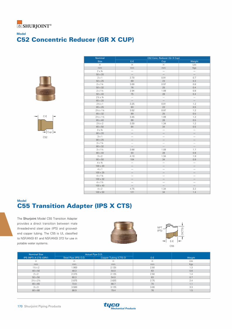
Mechanical Products170 Shurjoint Piping Products
Model
C52 Concentric Reducer (GR X CUP)
Nominal C52 Conc. Reducer (Gr X Cup) Size E-E Cup Weight in in in Lbs mm mm mm Kgs 2 x ¾ --- --- --- 50 x 20 --- --- --- 2 x 1 2.70 0.91 0.7 50 x 25 69 23 0.3 2 x 1¼ 3.00 0.97 0.8 50 x 32 76 25 0.4 2 x 1½ 2.94 1.09 0.8 50 x 40 75 28 0.4 2½ x ¾ --- --- --- 65 x 20 --- --- --- 2½ x 1 3.25 0.91 1.2 65 x 25 83 23 0.5 2½ x 1¼ 3.52 0.97 1.2 65 x 32 89 25 0.5 2½ x 1½ 3.45 1.09 1.2 65 x 40 88 28 0.5 2½ x 2 3.30 1.34 1.2 65 x 50 84 34 0.5 3 x ¾ --- --- --- 80 x 20 --- --- --- 3 x 1 --- --- --- 80 x 25 --- --- --- 3 x 1¼ --- --- --- 80 x 32 --- --- --- 3 x 1½ 3.68 1.09 1.7 80 x 40 93 28 0.8 3 x 2 4.10 1.34 1.9 80 x 50 104 34 0.9 4 x ¾ --- --- --- 100 x 20 --- --- --- 4 x 1 --- --- --- 100 x 25 --- --- --- 4 x 1¼ --- --- --- 100 x 32 --- --- --- 4 x 1½ --- --- --- 100 x 40 --- --- --- 4 x 2 4.75 1.34 3.2 100 x 50 121 34 1.4
The Shurjoint Model C55 Transition Adapter
provides a direct transition between male
threaded-end steel pipe (IPS) and grooved-
end copper tubing. The C55 is UL classified
to NSF/ANSI 61 and NSF/ANSI 372 for use in
potable water systems.
Model
C55 Transition Adapter (IPS X CTS)
Nominal Size Actual Pipe O.D. IPS (NPT) X CTS (GRV) Steel Pipe (IPS) O.D. Copper Tubing (CTS) D E-E Weight in in in in Lbs mm mm mm mm Kgs 1½ x 2 1.900 2.125 2.50 1.3 40 x 50 48.3 54.0 63 0.6 2 x 2 2.375 2.125 2.50 1.4 50 x 50 60.3 54.0 63 0.7 2½ x 2½ 2.875 2.625 2.75 2.4 65 x 65 73.0 66.7 70 1.1 3 x 3 3.500 3.125 3.00 3.3 80 x 80 88.9 79.4 76 1.5
C55
D(C
TS)NPT
(IPS)
E-E
C52
Cup
C-E

Mechanical ProductsShurjoint Piping Products 171
Nominal Actual Pipe O.D. Size Steel Pipe Copper Tubing E-E Weight in in in in Lbs mm mm mm mm Kgs 2 2.375 2.125 4.00 1.3 50 60.3 54.0 102 0.6 2½ 2.875 2.625 4.00 1.9 65 73.0 66.7 102 0.9 3 3.500 3.125 4.00 2.9 80 88.9 79.4 102 1.3 4 4.500 4.125 4.00 3.3 100 114.3 104.8 102 1.5 5 5.563 5.125 4.00 5.2 125 141.3 130.2 102 2.4 6 6.625 6.125 4.00 6.9 150 168.3 155.6 102 3.1 8 8.625 8.125 4.00 9.4 200 219.1 206.4 102 4.3
Allows for the installation of gauges or Pete's
Plugs for measuring temperature and or
pressure.
The Model DE30-GG Dielectric Transition
Fitting provides a direct transition between
grooved-end steel pipe (IPS) and grooved-end
copper tubing (CTS). The internal PP lining
effectively eliminates galvanic local cell and
stray current problems.
Model
C55T Transition Adapter (IPS/FT X CTS/GR) with ¼" Taps
Model
DE30-GG Dielectric Transition Fitting (IPS X CTS)
Nominal Size Steel Pipe (IPS) Copper Tubing (CTS) IPS (NPT) X CTS (GRV) O.D. D E-E Weight in in in in Lbs mm mm mm mm Kgs 1½ x 2 1.900 2.125 2.50 1.1 40 x 50 48.3 54.0 63 0.5 2 x 2 2.375 2.125 2.50 1.3 50 x 50 60.3 54.0 63 0.6 2½ x 2½ 2.875 2.625 2.75 2.0 65 x 65 73.0 66.7 70 0.9 3 x 3* 3.500 3.125 3.00 3.3 80 x 80 88.9 79.4 76 1.5
*Non-standard/stock items may require longer lead time.
C55T
¼" NPT
¼" NPT D(C
TS)NPT
(IPS)
E-E
E-E
Virgin PP Lining
Ductile Iron Body
Pete's Plug
(CTS)
C305C55T
(IPS)

Mechanical Products172 Shurjoint Piping Products
Use a torque wrench and tighten the nuts to an approximate torque value of 5 Lbs-Ft ~ 9 Lbs-Ft (20 Nm ~ 30 Nm). Excess torque may cause joint failure.
The Shurjoint Model C723 provides a fast,
easy and reliable branch connection from
copper tubing (CTS). The fitting consists of
a bronze upper housing, ductile iron lower
housing, o-ring and carbon steel track bolts
and nuts. The fitting is available with a female
threaded outlet, NPT or BSPT.
Model
C723 Bronze Mechanical Tee for Copper Tubing (CTS)
Max. Working Hole Dia. Dimensions Nominal Pressure +0.063, -0 / Bolt Weight CTS X NPT (CWP)* +1.6, -0 A B C D T** Size in PSI in in in in in in
in Lbs
mm Bar mm mm mm mm mm mm Kgs 2½ x ½ 200 1.18 2.56 1.61 4.65 1.89 2.09 ⅜ x 2⅛ 1.5 65 x 15 14 30 65 41 118 48 53 0.7 2½ x ¾ 200 1.18 2.56 1.61 4.65 2.01 2.05 ⅜ x 2⅛ 1.5 65 x 20 14 30 65 41 118 51 52 0.7 2½x 1 200 1.18 2.56 1.61 4.65 1.89 1.93 ⅜ x 2⅛ 1.5 65 x 25 14 30 65 41 118 48 49 0.7 2½ x 1¼ 200 1.77 2.68 1.61 4.65 2.64 2.15 ⅜ x 2⅛ 2.2 65 x 32 14 45 68 41 118 67 55 1.0 3 x ¾ 200 1.18 2.80 1.89 5.16 2.01 2.28 ⅜ x 2⅛ 1.5 80 x 20 14 30 71 48 131 51 58 0.7 3 x 1 200 1.18 2.80 1.89 5.16 1.89 2.20 ⅜ x 2⅛ 1.8 80 x 25 14 30 71 48 131 48 56 0.8 3 x 1¼ 200 1.77 2.95 1.89 5.16 2.64 2.59 ⅜ x 2⅛ 2.2 80 x 32 14 45 75 48 131 67 66 1.0 4 x ¾ 200 1.18 3.35 2.36 6.22 2.01 2.80 ⅜ x 2⅛ 1.8 100 x 20 14 30 85 60 158 51 71 0.8 4 x 1 200 1.18 3.35 2.36 6.22 1.89 3.11 ⅜ x 2⅛ 1.8 100 x 25 14 30 85 60 158 48 79 0.8 4 x 1¼ 200 1.77 3.35 2.36 6.22 2.64 3.11 ⅜ x 2⅛ 1.9 100 x 32 14 45 85 60 158 67 79 0.9
* Working pressure is for connection with Type K copper tubing.**T: Center of run to engaged pipe end (approx.).
AB
C D
T

Mechanical ProductsShurjoint Piping Products 173
The Shurjoint Model C726 Y-Strainer can
be installed quickly and easily with two
mechanical couplings and the straight flow
through design provides for lower pressure
drop.
Model
C726 Y-Strainer for Copper Tubing (CTS)
Max. Dimensions Drain Nominal Pipe Working Pressure Plug Size O.D. (CWP)* A B C Size Weight in in PSI in in in in Lbs mm mm Bar mm mm mm mm Kgs 2 2.125 300 8.75 6.38 3.18 ½ 8.8 50 54.0 20 222 162 81 15 4.0 2½ 2.625 300 9.75 6.97 4.72 ½ 11.3 65 66.7 20 248 177 120 15 5.1 3 3.125 300 10.63 7.71 4.50 ½ 15.0 80 79.4 20 270 196 114 15 6.8 4 4.125 300 13.00 9.60 6.00 1 27.5 100 104.8 20 330 244 152 25 12.5 6 6.125 300 17.00 12.91 8.00 1 59.3 150 155.6 20 432 328 203 25 26.9
* Working pressure is for connection with roll-grooved Type K copper tubing.
2"~12"
BC
A

Mechanical Products174 Shurjoint Piping Products
The Shurjoint Model SJ-C300 is a lever
handle bronze body butterfly valve designed
for use with grooved copper tubing (CTS),
fittings and couplings. The lead-free bronze
body conforms to ASTM B584 copper alloy
Model
SJ-C300 Butterfly Valve for Copper Tubing (CTS)
C90500 (88-10-0-2) or C89836 Bismuth
copper alloy which are UL classified
in accordance with NSF/ANSI 61 and
NSF/ANSI 372 for potable water use.
*Working pressure is for connection with roll-grooved Type K copper tubing.** Please note that 2”, 2½”, and 3” Model C341 Flanges cannot be used for making direct connections to Model SJ-C300 Butterfly Valves due to bolt pad interference with the valve.
Max. Dimensions Nominal Pipe Working Pressure Size O.D. (CWP)* A B C D Weight in in PSI in in in in Lbs mm mm Bar mm mm mm mm Kgs 2 2.125 300 3.19 5.31 2.45 10.0 5.9 50 54 20 81 135 57 254 2.7 2½ 2.625 300 3.78 5.87 2.87 10.0 7.3 65 66.7 20 96 149 73 254 3.3 3 3.125 300 3.78 6.42 3.27 10.0 7.7 80 79.4 20 96 163 83 254 3.5 4 4.125 300 4.65 8.19 4.29 10.0 11.0 100 104.8 20 118 208 109 254 5.0 5 5.125 300 5.28 9.80 5.36 10.0 16.9 125 130.2 20 134 249 136 254 7.7 6 6.125 300 5.28 10.79 6.42 10.0 16.9 150 155.6 20 134 274 163 254 7.7
S
O
O.D.
C
C
B
A
D
Mechanical ProductsShurjoint Piping Products 175
Notes

Mechanical Products176 Shurjoint Piping Products
Notes

Mechanical ProductsShurjoint Piping Products 177
AWWA Ductile Iron Series .................................................................... 178
Radius Cut Groove Specifications ....................................................... 178
AWWA Grooved Couplings & Flange Adapters
A505 Coupling ................................................................................... 179
A507 Transition Coupling .................................................................. 180
A512 Flange Adapter ......................................................................... 180
Grooved Fittings
A10 / A11 / A20 / A60 Elbows, Tee & Cap ........................................ 181
A25 / A50 / A10R Reducing Tee, Concentric Reducer & Reducing
Elbow ................................................................................................ 182
Section 9
AWWA Ductile Iron Series

Mechanical Products178 Shurjoint Piping Products
AWWA Ductile Iron Series
Shurjoint offers a variety of grooved mechanical couplings and fittings for AWWA ductile iron pipe in sizes 3” to 24”. The Shurjoint coupling features a two-piece housing and GapSeal gasket for a leak-tight seal. Ductile iron pipe shall be cut-grooved to AWWA C606 Table 2 and Table 3 - Radius Cut Groove Specifications.
Rubber gaskets are specially compounded to seal on ductile iron surfaces and are available in three grades to meet your service requirement needs. See page 179 for details.
Radius Cut Grooving Dimensions – Ductile Iron Pipe
Gasket Seating Surface (A):The same coupling can be used either as a rigid joint or a flexible joint depending on the groove. Gasket seat “A Rigid” is for rigid joints and Gasket seat “A Flex.” for flexible joints.The gasket seating surface shall be free from deep scores, marks, or ridges that could prevent a positive seal.Groove Diameter (C):The “C” diameters are average values. The groove must be of uniform depth around the entire pipe circumference.Radius (R):The groove must be cut with a radius ‘R’ at the corners of the groove to reduce stress concentration.Minimum Wall Thickness (T):“T” is the minimum allowable wall thickness that may be cut-grooved; tolerances are to conform to ANSI/AWWA C151/ A21.51.
AWWA Ductile Iron Pipe
Pipe O.D. Gasket Seat A Groove Groove Dia. C Min. Nominal Rigid Flex. Width B Allowed Size Basic Tolerance +0/-0.02 +0.016/-0.047 +0.031/-0.016 Tol. Radius Wall + - +0/-0.51 +0.41/-1.19 +0.79/-0.41 Basic +0 +0 R Thickness T in in in in in in in in in in in mm mm mm mm mm mm mm mm mm mm mm 3 3.96 +0.045 -0.045 0.840 0.750 0.375 3.723 -0.020 0.120 0.31 80 100.6 +1.14 -1.14 21.34 19.05 9.53 94.56 -0.51 3.05 7.9 4 4.80 +0.045 -0.045 0.840 0.750 0.375 4.563 -0.020 0.120 0.32 100 121.9 +1.14 -1.14 21.34 19.05 9.53 115.90 -0.51 3.05 8.1 6 6.90 +0.060 -0.060 0.840 0.750 0.375 6.656 -0.020 0.120 0.34 150 175.3 +1.52 -1.52 21.34 19.05 9.53 169.06 -0.51 3.05 8.6 8 9.05 +0.060 -0.060 0.840 0.875 0.500 8.781 -0.025 0.145 0.36 200 229.9 +1.52 -1.52 21.34 22.83 12.70 223.04 -0.64 3.68 9.1 10 11.10 +0.060 -0.060 1.015 0.938 0.500 10.813 -0.025 0.145 0.38 250 281.9 +1.52 -1.52 25.78 23.83 12.70 274.65 -0.64 3.68 9.7 12 13.20 +0.060 -0.060 1.015 0.938 0.500 12.906 -0.030 0.145 0.40 300 335.3 +1.52 -1.52 25.78 23.83 12.70 327.81 -0.76 3.68 10.2 14 15.30 +0.050 -0.080 1.015 0.938 0.625 14.969 -0.030 0.165 0.42 350 388.6 +1.27 -2.03 25.78 23.83 15.88 380.21 -0.76 4.19 10.7 16 17.40 +0.050 -0.080 1.340 1.188 0.625 17.063 -0.030 0.165 0.43 400 442.0 +1.27 -2.03 34.04 30.18 15.88 433.40 -0.76 4.19 10.9 18 19.50 +0.050 -0.080 1.340 1.188 0.625 19.125 -0.030 0.185 0.44 450 495.3 +1.27 -2.03 34.04 30.18 15.88 485.78 -0.76 4.70 11.2 20 21.60 +0.050 -0.080 1.340 1.188 0.625 21.219 -0.030 0.185 0.45 500 548.6 +1.27 -2.03 34.04 30.18 15.88 538.96 -0.76 4.70 11.4 24 25.80 +0.050 -0.080 1.340 1.188 0.625 25.046 -0.030 0.185 0.47 600 655.3 +1.27 -2.03 34.04 30.18 15.88 645.31 -0.76 4.70 11.9
B
C
T
A
BR
O.D
.

Mechanical ProductsShurjoint Piping Products 179
General Service Recommendations
Specially formulated to seal on ductile iron pipe iron
surfaces. Recommended for petroleum products, air
with oil vapors, vegetable and mineral oils within the
specified temperature range; except hot dry air over
+140°F (60°C) and water over +150°F (65°C)
Not Recommended for Hot Water Services.
Specially formulated to seal on ductile iron pipe
surfaces. Recommended for water service plus a variety
of dilute acids, oil-free air and other chemical services
within the specified temperature range. The compound
is UL classified per NSF/ANSI 61 and NSF/ANSI 372 for
potable water applications.
Not Recommended for Hot Water Services.
Recommended for dry heat, air without hydrocarbons to
350°F (177°C) and certain chemical services.
Grade
S
M
L
Temp. Range
-20°F to + 180°F (-29°C to +82°C)
-20°F to + 200°F (-29°C to +93°C)
-30°F to + 350°F (-34°C to +177°C)
Compound
Nitrile
Halogenated Butyl
Silicone
Color Code
Red Stripe
Brown Stripe
Red Gasket
Special gaskets for AWWA ductile iron pipe
Shurjoint Model A505 Couplings are
designed for connecting grooved ductile
iron pipe and fittings of ANSI/AWWA C151/
A21.51, Class 53 or higher dimensions.
The same coupling can be used either as a
flexible coupling or a rigid coupling depending
on the type of groove processed. The Model
A505 Coupling is recommended for service
up to 500 psi (35 Bar) depending on the size.
Model
A505 Coupling
The GapSeal gasket fits flush over the pipe
ends and prevents fluids from entering into
the gasket cavity.
* Pressure ratings listed are based on radius cut-grooved Thickness Class 53 or higher pipe.†
AWWA D.I. Pipe Max. Working Max. End Axial Bolt Dimensions Nominal Size Pipe O.D. Pressure (CWP)* Load Displacement † No. Size A B C Weight in in PSI Lbs in
in in in in Lbs
mm mm Bar kN mm mm mm mm Kgs 3 3.96 500 6200 0~0.09
2 ½ x 3 5.33 7.36 2.40 5.5
80 100.6 35 27.59 0~2.4 136 187 61 2.5 4 4.80 500 9000 0~0.09
2 ⅝ x 3½ 6.96 8.33 2.32 7.3
100 121.9 35 40.50 0~2.4 157 212 59 3.3 6 6.90 400 14950 0~0.09
2 ⅝ x 3½ 9.37 10.75 2.44 9.7
150 175.3 28 66.26 0~2.4 211 273 62 4.4 8 9.05 400 25600 0~0.16
2 ¾ x 4¾ 12.07 13.94 2.64 18.7
200 229.9 28 113.92 0~4.0 272 354 67 8.5 10 11.10 350 33850 0~0.16
2 ¾ x 4¾ 14.50 16.06 2.95 24.2
250 281.9 24 150.63 0~4.0 326 408 75 11.0 12 13.20 350 47900 0~0.16
2 ⅞ x 6½ 16.89 18.19 2.95 30.8
300 335.3 24 211.50 0~4.0 380 462 75 14.0A
B C

Mechanical Products180 Shurjoint Piping Products
The Shurjoint Model A507 Transition
Coupling provides for a direct connection
between grooved end IPS steel pipe and
grooved end AWWA ductile iron pipe, fittings
and or valves. The A507 will accommodate
roll or cut grooved IPS steel pipe and rigid or
flexible AWWA ductile iron cut grooves.
The Shurjoint Model A512 Flange Adapter
provides for the direct connection between
AWWA ductile iron radius pipe grooves
and flanged components. The two part
flange features integral closure tabs to aid
in assembly. Note: As with other flange
adapters the A512 requires a sufficient
smooth flat mating area for proper sealing,
please refer to the A512 cut sheet or contact
Shurjoint for details.
AWWA D.I. Pipe Max. Working Max. End Bolt Dimensions Nominal Size Pipe O.D. Pressure (CWP)* Load No. Size A B C Weight in in PSI Lbs
in in in in Lbs
mm mm Bar kN mm mm mm Kgs 3 3.96 250 3100
4 ⅝ x 3 7.50 6.00 1.10 8.6
80 100.6 17 13.80 190 152 28 3.9 4 4.80 250 4500
8 ⅝ x 3 9.00 7.50 1.10 9.9
100 121.9 17 20.03 229 191 28 4.5 6 6.90 250 9300
8 ¾ x 3½ 11.00 9.49 1.10 12.0
150 175.3 17 41.39 279 241 28 5.4 8 9.05 250 16000
8 ¾ x 3½ 13.50 11.75 1.22 18.9
200 229.9 17 71.20 343 298 31 8.6 10 11.10 250 23700
12 ⅞ x 4 16.00 14.25 1.26 25.3
250 281.9 17 105.47 406 362 32 11.5 12 13.20 250 34000
12 ⅞ x 4 19.00 17.00 1.26 34.4
300 335.3 17 151.30 483 432 32 15.6
* Pressure ratings listed are based on radius cut-grooved Thickness Class 53 or higher pipe.** Flange drilling to ANSI B16.1 Class 125.
Model
A507 Transition Coupling
Model
A512 Flange Adapter
Nominal Pipe O.D. Max. Working Max. End Axial Bolt Dimensions Size IPS Steel AWWA Ductile Iron Pressure (CWP)* Load Displacement Size A B C Weight in in in PSI Lbs in
in in in in Lbs
mm mm mm Bar kN mm mm mm mm Kgs 3 3.500 3.96 500 4810 0.03
½ x 2¾ 5.31 7.28 2.13 4.8
80 88.9 100.6 35 21.41 1 135 185 54 2.2 4 4.500 4.80 500 7950 0.03 ⅝ x 3½
6.22 8.54 2.19 6.4 100 114.3 121.9 35 35.38 1 158 217 56 2.9 6 6.625 6.90 400 13780 0.03 ⅝ x 3½
8.23 10.75 2.19 8.6 150 168.3 175.3 28 61.32 1 209 273 56 3.9 8 8.625 9.05 400 23370 0.03
¾ x 4¾ 10.79 13.66 2.52 16.7
200 219.1 229.9 28 103.99 1 274 347 64 7.6 10 10.750 11.10 350 33850 0.03 ⅞ x 6½
13.03 16.10 2.76 24.9 250 273.0 281.9 24 155.96 1 331 409 70 11.3 12 12.750 13.20 350 47870 0.03 ⅞ x 6½
15.00 18.35 2.76 28.6 300 323.9 335.3 24 220.64 1 381 466 70 13.0
* Pressure ratings listed are based on radius cut-grooved Thickness Class 53 or higher pipe.
B C
A
BA C

Mechanical ProductsShurjoint Piping Products 181
Shurjoint AWWA grooved end fittings are
supplied with rigid radius grooves as per
ANSI / AWWA C606. The fittings also
conform to ANSI A21.10 / AWWA C110
for center to end (C to E) dimensions and
AWWA C153 or ANSI A21.10 / AWWA
C110 for wall thickness. Pressure ratings are
500 psi (35 Bar). Fittings are supplied painted
black. Other surface finish options including
'non-coated' and cement/mortar lining Type II
are available on request.
AWWA A10 A11 A20 A60 D.I. Pipe 90° Elbow 45° Elbow Tee Cap Nom. Size O.D. C - E Weight C - E Weight C - E Weight E - E Weight in in in Lbs in Lbs in Lbs in Lbs mm mm mm Kgs mm Kgs mm Kgs mm Kgs 3 3.96 5.50 9.2 3.00 5.8 5.50 13.4 1.22 2.6 80 100.6 140 4.2 76 2.6 140 6.1 31 1.2 4 4.80 6.50 12.3 4.00 9.2 6.50 18.5 1.22 3.5 100 121.9 165 5.6 102 4.2 165 8.4 31 1.6 6 6.90 8.00 23.5 5.00 17.6 8.00 35.0 1.22 6.8 150 175.3 203 10.7 127 8.0 203 15.9 31 3.1 8 9.05 9.00 41.6 5.50 33.0 9.00 60.3 1.46 13.0 200 229.9 229 18.9 140 15.0 229 27.4 37 5.9 10 11.10 11.00 64.9 6.50 44.9 11.00 110.5 2.99 22.0 250 281.9 279 29.5 165 20.4 279 45.7 76 10.0 12 13.20 12.00 94.2 7.50 72.0 12.00 136.0 2.99 24.6 300 335.3 305 42.8 191 32.7 305 61.7 76 11.2
AWWA Grooved FittingsModel
A10 90° Elbow A11 45° ElbowA20 Tee A60 Cap
A1090˚ Elbow
C-E
A1145˚ Elbow
C-E
10''~ 12''4''~ 8''
A60 Cap
E-EE-E
A20 Tee
C-E
C-E
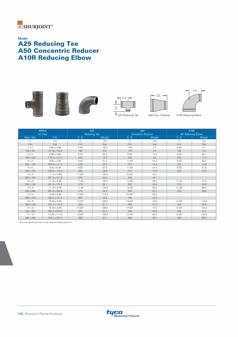
Mechanical Products182 Shurjoint Piping Products
Model
A25 Reducing Tee A50 Concentric Reducer A10R Reducing Elbow
AWWA A25 A50 A10R D.I. Pipe Reducing Tee Concentric Reducer 90° Reducing Elbow Nom. Size O.D. C - E Weight E - E Weight C - E Weight in Lbs in Lbs in Lbs in Lbs mm Kgs mm Kgs mm Kgs mm Kgs 4 x 3 4.80 x 3.96 6.50 18.8 7.00 7.7 6.50 12.1 100 x 80 121.9 x 100.6 165 8.5 178 3.5 165 5.5 6 x 4 6.90 x 4.80 8.00 33.3 9.00 14.3 8.00 25.1 150 x 100 175.3 x 121.9 203 15.2 229 6.5 203 11.4 8 x 4 9.05 x 4.80 9.00 51.2 11.00 24.0 9.00 43.5 200 x 100 229.9 x 121.9 229 23.3 279 10.9 229 19.8 8 x 6 9.05 x 6.90 9.00 57.2 11.00 24.0 9.00 41.8 200 x 150 229.9 x 175.3 229 26.0 279 12.6 229 19.0 10 x 4 11.10 x 4.80 11.00* 120.0 12.00* 42.0 - - 250 x 100 281.9 x 121.9 279 54.4 305 19.1 - - 10 x 6 11.10 x 6.90 11.00 128.0 12.00 46.0 11.00 77.0 250 x 150 281.9 x 175.3 279 58.1 305 20.9 279 34.9 10 x 8 11.10 x 9.05 11.00 130.0 12.00 50.0 11.00 88.0 250 x 200 281.9 x 229.9 279 59.0 305 22.7 279 39.9 12 x 4 13.20 x 4.80 12.00* 112.0 14.00* 60.0 - - 300 x 100 335.3 x 121.9 305 50.8 356 27.2 - - 12 x 6 13.20 x 6.90 12.00* 180.0 14.00* 70.0 12.00* 110.0 300 x 150 335.3 x 175.3 305 81.7 356 31.8 305 49.9 12 x 8 13.20 x 9.05 12.00* 186.0 14.00* 74.0 12.00* 126.0 300 x 200 335.3 x 229.9 305 84.4 356 33.6 305 57.2 12 x 10 13.20 x 11.10 12.00* 192.0 14.00 84.0 12.00* 150.0 300 x 250 335.3 x 281.9 305 87.1 356 38.1 305 68.0
* Non-standard/stock items may require longer lead time.
A10R Reducing ElbowA50 Conc. ReducerA25 Reducing Tee
C-E
C-E
E-E
C-E

Mechanical ProductsShurjoint Piping Products 183
Notes

Mechanical Products184 Shurjoint Piping Products
Notes

Mechanical ProductsShurjoint Piping Products 185
Pipe End Preparation ..................................................................... 186
Roll Grooving Dimensions for ANSI, BS & AS pipe ........................... 187
Roll Grooving Dimensions for ISO pipe ............................................. 188
Roll Grooving Dimensions for KS & JIS pipe ..................................... 189
Roll Grooving Dimensions for Large Diameter IPS Pipe ................... 189
Cut Grooving Dimensions for IPS, BS, AS, ISO, JIS & KS pipe ......... 190
Typical Applications –
Flexible Couplings (General Systems) ............................................. 191
Anchoring, Hanging and Supports........................................... 193
Gasket Selection Guide ................................................................ 196
General Gasket Service Recommendations ...................................... 198
Fire Protection Services ................................................................ 202
Approved Pressure Ratings by UL & FM .......................................... 203
Listed Pressure Ratings by IAPMO ................................................... 205
Typical Applications – Flexible Couplings – Sprinkler Systems
(NFPA 13) .......................................................................................... 207
Section 10
Technical Information

Mechanical Products186 Shurjoint Piping Products
Pipe End Preparation How to process roll-grooves
Shurjoint grooved piping systems require the processing of a roll or cut groove to the pipe ends being connected. The engagement of the housing keys in the grooves is integral in providing a secure and leak-tight joint. It is essential that the grooves are properly processed for optimum joint performance.
Nominal pipe sizeShurjoint couplings and fittings are identified by the nominal IPS
pipe size in inches or nominal diameter of pipe (DN) in millimeters.
Always check the actual O.D. of the pipe and fittings to be
connected, as in some markets it is customary to refer to different
O.D. pipes with the same nominal size.
Roll groove profileRoll grooves should be as defined as possible. To achieve optimum
joint performance the “K” dimension should be as small as possible.
When processing a roll groove the machine operator should manage
the feed pressure of the upper roll set so as to achieve the best
possible groove profile.
Applicable pipe wall thicknessRoll grooves are generally applicable to .375”/9.5 mm thick or
thinner wall carbon steel pipe, stainless steel pipe, copper tube and
aluminum pipe depending on the type of roll-grooving machine and
roll set being used. Different wall thicknesses and sizes require
the use of different roll sets. Contact the roll groove machine
manufacturer for additional information.
Heavy wall pipeWhen you attempt to roll-groove pipe thicker than .375”/9.5mm,
the metal may deform and heap up on both sides of the groove
rather than radially deforming and protruding on the inside of the
pipe. The extra heaped metal could lead to joint failure. In such a
case, you should grind off any such extra metal to achieve a flat and
smooth sealing surface. A proper rust preventative coating must be
applied on the ground surface. Shurjoint strongly recommends the
processing of cut-grooves on heavy or thick wall pipe.
Plain end pipe and beveled end pipe While plain-end pipe is preferred, the use of beveled end pipe is
acceptable providing that the wall thickness is .375”/9.5 mm or
thinner and the bevel is 37½ ±2½° or 30° as specified in ANSI
B16.25 and ASTM A-53 respectively.
ERW pipeERW pipe is one of the most popular types of pipe used today.
Depending on the individual pipe and manufacturer, welding beads
may remain on the surface (inside and outside) of the pipe. Always
remove harmful weld beads near the pipe ends as they can cause
rattling of the roll grooving machine resulting in inaccurate grooves.
Galvanized pipe Galvanized pipe is acceptable as long as the gasket seating surface
is smooth and free from scale and imperfections that could affect
gasket sealing. Whenever you remove welding beads or projections
from the sealing surface of galvanized pipe, use caution so as to not
over-grind the surface. After grinding, always apply a proper rust-
prevention coating to this area.
Spiral welded pipeSpiral welded pipe may be used as long as the weld beads are
removed from the gasket seating surface. It is also acceptable and
recommended to weld a grooved end nipple to the pipe end as
shown below. Whenever you remove weld beads or projections
from the gasket seating surface, use caution so as to not over-grind
the surface. After grinding, always apply a proper rust-prevention
coating to this area.
KeyHousing
Pipe
Rubber gasket
Groove Full engagement
A B
K B1
C
Thicker than 0.375” (9.5mm)
No or very little protrusion
37½° or 30°
Beveled-end Pipe(ANSI B16.25 / ASTM A-53)
Welded
Spiral pipe witha grooved nipple

Mechanical ProductsShurjoint Piping Products 187
Roll Grooving Dimensions for ANSI B36.10, BS 1387 (M) & AS-1074 (M) Pipe
Basic roll groove dimensions conform to ANSI/AWWA C606-06
Table 5 with slightly adjusted tolerances to incorporate international
standards including CSA B242, ISO/FDIS 6152-12, VdS 2100-6en and
JPF MP-006.
Nominal Pipe O.D. A B C Min. d F Size
Basic
Tolerance ±0.030 ±0.030 +0.000 Wall Groove Max. Allowed
±0.76 ±0.76 +0.00 t Depth d (ref.) Flare Dia. in in in in in in in in in in mm mm mm mm mm mm mm mm mm mm ¾ 1.050 +0.010 -0.010 0.625 0.281 0.938-0.015 0.065 0.056 1.15 20 26.7 +0.25 -0.25 15.88 7.14 23.83-0.38 1.65 1.42 29.21 1 1.315 +0.013 -0.013 0.625 0.281 1.190-0.015 0.065 0.063 1.43 25 33.4 +0.33 -0.33 15.88 7.14 30.23-0.38 1.65 1.60 36.30 1¼ 1.660 +0.016 -0.016 0.625 0.281 1.535-0.015 0.065 0.063 1.77 32 42.2 +0.41 -0.41 15.88 7.14 38.99-0.38 1.65 1.60 44.96 1½ 1.900 +0.019 -0.019 0.625 0.281 1.775-0.015 0.065 0.063 2.01 40 48.3 +0.48 -0.48 15.88 7.14 45.09-0.38 1.65 1.60 51.05 2 2.375 +0.024 -0.024 0.625 0.344 2.250-0.015 0.065 0.063 2.48 50 60.3 +0.61 -0.61 15.88 8.74 57.15-0.38 1.65 1.60 62.99 2½ 2.875 +0.029 -0.029 0.625 0.344 2.720-0.018 0.083 0.078 2.98 65 73.0 +0.74 -0.74 15.88 8.74 69.09-0.46 2.11 1.98 75.69
76.1 mm 3.000 +0.030 -0.030 0.625 0.344 2.844-0.018 0.090 0.075 3.10
76.1 +0.76 -0.76 15.88 8.74 72.24-0.46 2.30 1.93 78.74 3 3.500 +0.035 -0.031 0.625 0.344 3.344-0.018 0.083 0.078 3.60 80 88.9 +0.89 -0.79 15.88 8.74 84.94-0.46 2.11 1.98 91.44
101.6 mm 4.000 +0.040 -0.031 0.625 0.344 3.834-0.020 0.083 0.083 4.10
101.6 +1.02 -0.79 15.88 8.74 97.38-0.51 2.11 2.11 104.10
108.0 mm 4.250 +0.042 -0.031 0.625 0.344 4.084-0.020 0.083 0.083 4.35
108.0 +1.07 -0.79 15.88 8.74 103.73-0.51 2.11 2.11 110.49 4 4.500 +0.040 -0.031 0.625 0.344 4.334-0.020 0.083 0.083 4.60 100 114.3 +1.02 -0.79 15.88 8.74 110.08-0.51 2.11 2.11 116.84
133.0 mm 5.250 +0.051 -0.031 0.625 0.344 5.084-0.020 0.109 0.083 5.35
133.0 +1.32 -0.79 15.88 8.74 129.13-0.51 2.77 2.11 135.89
139.7 mm 5.500 +0.050 -0.031 0.625 0.344 5.333-0.020 0.109 0.083 5.60
139.7 +1.40 -0.79 15.88 8.74 135.46-0.51 2.77 2.11 142.24 5 5.563 +0.056 -0.031 0.625 0.344 5.395-0.022 0.109 0.083 5.66 125 141.3 +1.42 -0.79 15.88 8.74 137.03-0.56 2.77 2.11 143.76
159.0 mm 6.250 +0.063 -0.031 0.625 0.344 6.084-0.030 0.109 0.083 6.35
159.0 +1.60 -0.79 15.88 8.74 154.53-0.76 2.77 2.11 161.29
165.1 mm 6.500 +0.063 -0.031 0.625 0.344 6.334-0.022 0.109 0.085 6.60
165.1 +1.60 -0.79 15.88 8.74 160.88-0.56 2.77 2.16 167.64 6 6.625 +0.063 -0.031 0.625 0.344 6.455-0.022 0.109 0.085 6.73 150 168.3 +1.60 -0.79 15.88 8.74 163.96-0.56 2.77 2.16 170.94
216.3 mm 8.516 +0.063 -0.031 0.750 0.469 8.331-0.025 0.109 0.092 8.69
216.3 +1.60 -0.79 19.05 11.91 211.61-0.64 2.77 2.34 220.73 8 8.625 +0.063 -0.031 0.750 0.469 8.441-0.025 0.109 0.092 8.80 200 219.1 +1.60 -0.79 19.05 11.91 214.40-0.64 2.77 2.34 223.52 10 10.750 +0.063 -0.031 0.750 0.469 10.562-0.027 0.134 0.094 10.92 250 273.0 +1.60 -0.79 19.05 11.91 268.27-0.69 3.40 2.39 277.37 12 12.750 +0.063 -0.031 0.750 0.469 12.531-0.030 0.156 0.109 12.92 300 323.9 +1.60 -0.79 19.05 11.91 318.29-0.76 3.96 2.77 328.17 14 14.000 +0.063 -0.031 0.938 0.469 13.781-0.030 0.156 0.109 14.10 350 355.6 +1.60 -0.79 23.83 11.91 350.04-0.76 3.96 2.77 358.14 16 16.000 +0.063 -0.031 0.938 0.469 15.781-0.030 0.165 0.109 16.10 400 406.4 +1.60 -0.79 23.83 11.91 400.84-0.76 4.19 2.77 408.94 18 18.000 +0.063 -0.031 1.000 0.469 17.781-0.030 0.165 0.109 18.16 450 457.2 +1.60 -0.79 25.40 11.91 451.64-0.76 4.19 2.77 461.26 20 20.000 +0.063 -0.031 1.000 0.469 19.781-0.030 0.188 0.109 20.16 500 508.0 +1.60 -0.79 25.40 11.91 502.44-0.76 4.78 2.77 512.06 22 22.000 +0.063 -0.031 1.000 0.469 21.656-0.030 0.188 0.172 22.20 550 558.8 +1.60 -0.79 25.40 11.91 550.06-0.76 4.78 4.37 563.88 24 24.000 +0.063 -0.031 1.000 0.500 23.656-0.030 0.218 0.172 24.20 600 609.6 +1.60 -0.79 25.40 12.70 600.86-0.76 5.54 4.37 614.68
1. Pipe O.D.: Maximum allowable tolerances from square cut ends is 0.03" for sizes up to 3½"; 0.045" for 4" thru 6"; and 0.060" for sizes 8" and above.2. The gasket seating surface "A" shall be free from deep scores, marks, or ridges that would prevent a positive seal.3. The "C" dimensions are average values. The groove must be of uniform depth around the entire circumference. Use a Shurjoint groove gage or rule to check the groove diameter. 4. The "t" is the minimum allowable wall thickness that may be roll-grooved.5. The "d" is for reference use only. The groove depth shall be determined by the groove diameter "C".6. Flare Diameter: The pipe end that may flare when the groove is rolled shall be within this limit when measured at the extreme end of the pipe.
AB
C
d
t
O.D. F

Mechanical Products188 Shurjoint Piping Products
Roll Grooving Dimensions per ISO/FDIS 6182-12 Table 1For ISO 4200:1991 Plain-end Steel Tubes, Welded and Seamless (Superseding BS1387 and DIN 2440 & DIN 2448)
t
A
ØO
D
d
ØC
ØF
B
Figure 1 - Roll grooved-end dimensional reference points for Table 1
Dimensions in millimeters
Pipe or tube Dimensional specifications Nominal Outside diameter (O.D.) Gasket seat Gasket width Grooved diameter C Groove Wall Thickness Flare F size Actual Tolerance A B Actual Tolerance depth t Max. size ±0.76 ±0.76 size d Min. allow. Dia. 25 33,7 +0,41 / -0,68 15,88 7,14 30,23 0 / -0,38 1,70 1,8 34,5 32 42,4 +0,50 / -0,60 15,88 7,14 38,99 0 / -0,38 1,70 1,8 43,3 40 48,3 +0,44 / -0,52 15,88 7,14 45,09 0 / -0,38 1,60 1,8 49,4 50 60,3 ±0,61 15,88 8,74 57,15 0 / -0,38 1,60 1,8 62,2 65 73,0 ±0,74 15,88 8,74 69,09 0 / -0,46 1,98 2,3 75,2 65 76,1 ±0,76 15,88 8,74 72,26 0 / -0,46 1,93 2,3 77,7 80 88,9 +0,89 / -0,79 15,88 8,74 84,94 0 / -0,46 1,98 2,3 90,6 90 101,6 +1,02 / -0,79 15,88 8,74 97,38 0 / -0,51 2,11 2,3 103,4 100 108,0 +1,07 / -0,79 15,88 8,74 103,73 0 / -0,51 2,11 2,3 109,7 100 114,3 +1,14 / -0,79 15,88 8,74 110,08 0 / -0,51 2,11 2,3 116,2 125 133,9 +1,32 / -0,79 15,88 8,74 129,13 0 / -0,51 1,93 2,9 134,9 125 139,7 +1,40 / -0,79 15,88 8,74 135,48 0 / -0,56 2,11 2,9 141,7 125 141,3 +1,42 / -0,79 15,88 8,74 137,03 0 / -0,56 2,13 2,9 143,5 150 159,0 +1,60 / -0,79 15,88 8,74 154,50 0 / -0,56 2,20 2,9 161,0 150 165,1 +1,60 / -0,79 15,88 8,74 160,90 0 / -0,56 2,16 2,9 167,1 150 168,3 +1,60 / -0,79 15,88 8,74 163,96 0 / -0,56 2,16 2,9 170,7 200 219,1 +1,60 / -0,79 19,05 11,91 214,40 0 / -0,64 2,34 2,9 221,5 250 277,4 +1,60 / -0,79 19,05 11,91 268,28 0 / -0,69 2,39 3,6 275,4 300 328,2 +1,60 / -0,79 19,05 11,91 318,29 0 / -0,76 2,77 4,0 326,2
1. Pipe O.D.: Maximum allowable tolerances from square cut ends is 0.03" for sizes up to 3½"; 0.045" for 4" thru 6"; and 0.060" for sizes 8" and above.2. The gasket seating surface "A" shall be free from deep scores, marks, or ridges that would prevent a positive seal.3. The "C" dimensions are average values. The groove must be of uniform depth around the entire circumference. Use a Shurjoint groove gage or rule to check the groove diameter. 4. The "t" is the minimum allowable wall thickness that may be roll-grooved.5. The "d" is for reference use only. The groove depth shall be determined by the groove diameter "C".6. Flare Diameter: The pipe end that may flare when the groove is rolled shall be within this limit when measured at the extreme end of the pipe.

Mechanical ProductsShurjoint Piping Products 189
Roll Grooving Dimensions for KS D3507 & JIS G3452 Carbon Steel Pipe
Nominal size Gasket Groove Groove Dia. C Groove Max. Allowed Pipe Seat A Width B Tolerance Depth Flare Dia. A B O.D. +0.76* +0.76* Basic +0.00* d (ref) F mm in mm mm mm mm mm mm mm 25A 1 34.0 16.0 7.1 30.4 -0.38 1.80 35.5 32A 1¼ 42.7 16.0 7.1 39.1 -0.38 1.80 44.2 40A 1½ 48.6 16.0 7.1 45.0 -0.38 1.80 50.1 50A 2 60.5 16.0 8.7 56.9 -0.38 1.80 62.0 65A 2½ 76.3 16.0 8.7 72.2 -0.46 2.05 77.8 80A 3 89.1 16.0 8.7 84.9 -0.46 2.10 90.6 100A 4 114.3 16.0 8.7 110.1 -0.51 2.10 116.8 125A 5 139.8 16.0 8.7 135.5 -0.56 2.15 142.3 150A 6 165.2 16.0 8.7 160.8 -0.56 2.20 167.7 200A 8 216.3 19.0 11.9 211.6 -0.64 2.35 219.8 250A 10 267.4 19.0 11.9 262.6 -0.69 2.40 270.9 300A 12 318.5 19.0 11.9 312.9 -0.76 2.80 322.0
* The tolerance for the JIS & KS pipe has a little difference.1. Pipe O.D.: Maximum allowable tolerances from square cut ends is 0.03" for sizes up to 3½"; 0.045" for 4" thru 6"; and 0.060" for sizes 8" and above.2. The gasket seating surface "A" shall be free from deep scores, marks, or ridges that would prevent a positive seal.3. The "C" dimensions are average values. The groove must be of uniform depth around the entire circumference. Use a Shurjoint groove gage or rule to check the groove diameter. 4. The "t" is the minimum allowable wall thickness that may be roll-grooved.5. The "d" is for reference use only. The groove depth shall be determined by the groove diameter "C".6. Flare Diameter: The pipe end that may flare when the groove is rolled shall be within this limit when measured at the extreme end of the pipe.
A
B
d
F C O.D.
1. Square cut: Max. allowable tolerances from square cut are 0.060" (1.6 mm).2. The gasket seating surface "A" shall be free from deep scores, marks, or ridges that would prevent a positive seal.3. The "C" dimensions are average values. The groove must be of uniform depth around the entire circumference. Use a Shurjoint groove or rule to check the groove diameter. 4. The "t" is the minimum allowable wall thickness that may be roll-grooved.5. The "d" is for reference use only. The groove depth shall be determined by the groove diameter "C".6. Flare Diameter: The pipe end that may flare when the groove is rolled shall be within this limit when measured at the extreme end of the pipe.
Nominal A B C d t F Max. Size
Pipe O.D. ±0.03 ±0.03 +0, -0.063 Groove Depth Min Allowed
Basic Tolerance ±0.8 ±0.8 +0, -1.6 (ref) Wali Flare Dia. in in in in in in in in in in mm mm mm mm mm mm mm mm mm mm 26 26.0 +0.093 -0.031 1.75 0.625 25.5 0.25 0.25 26.2 650 660.4 +2.36 -0.79 44.5 15.9 647.7 6.4 6.4 665.5 28 28.0 +0.093 -0.031 1.75 0.625 27.5 0.25 0.25 28.2 700 711.2 +2.36 -0.79 44.5 15.9 698.5 6.4 6.4 716.3 30 30.0 +0.093 -0.031 1.75 0.625 29.5 0.25 0.25 30.2 750 762.0 +2.36 -0.79 44.5 15.9 749.3 6.4 6.4 767.1 32 32.0 +0.093 -0.031 1.75 0.625 31.5 0.25 0.25 32.2 800 812.8 +2.36 -0.79 44.5 15.9 800.1 6.4 6.4 817.9 36 36.0 +0.093 -0.031 1.75 0.625 35.5 0.25 0.25 36.2 900 914.4 +2.36 -0.79 44.5 15.9 901.7 6.4 6.4 919.5 40 40.0 +0.093 -0.031 2.00 0.625 39.5 0.25 0.25 40.4 1000 1016.0 +2.36 -0.79 50.8 15.9 1003.3 6.4 6.4 1026.2 42 42.0 +0.093 -0.031 2.00 0.625 41.5 0.25 0.25 42.2 1050 1066.8 +2.36 -0.79 50.8 15.9 1054.1 6.4 6.4 1071.9
Roll Grooving Dimensions for Large Diameter IPS PipeANSI B36.10 A
C
d
B
t
O.D. F

Mechanical Products190 Shurjoint Piping Products
Cut Grooving Dimensions for IPS, BS, AS, ISO, JIS & KS Pipe
A
C
d
B
t
O.D.
1. Pipe OD: Maximum allowable tolerances from square of ends is 0.03” for sizes up to 3½”; 0.045” for 4” thru 6”, and 0.060” for sizes 8” and above.2. Gasket Seating Surface: The gasket seating surface shall be free from deep scores, marks, or ridges that would prevent a positive seal.3. Groove Width: Groove width is to be measured between vertical flanks of the groove side walls.4. Groove Diameter: The “C” diameters are average values. The groove must be of uniform depth around the entire pipe circumference. 5. Minimum Wall Thickness: The “t” is the minimum allowable wall thickness that may be cut-grooved.6. Groove Depth: The “d” is for reference use only. The groove dimension shall be determined by the groove diameter “C”.
Nominal Pipe O.D.
A B C t d Size ±0.031 ±0.031 +0.000 Min. Groove Depth Basic Tolerance ±0.79 ±0.79 +0.00 Wall (ref.) in in in in in in in in in mm mm mm mm mm mm mm mm mm ¾ 1.050 +0.010 -0.010 0.625 0.313 0.938-0.015 0.113 0.056 20 26.7 +0.25 -0.25 15.88 7.95 23.83-0.38 2.87 1.42 1 1.315 +0.013 -0.013 0.625 0.313 1.190-0.015 0.133 0.063 25 33.4 +0.33 -0.33 15.88 7.95 30.23-0.38 3.38 1.60 1¼ 1.660 +0.016 -0.016 0.625 0.313 1.535-0.015 0.140 0.063 32 42.2 +0.41 -0.41 15.88 7.95 38.99-0.38 3.56 1.60 1½ 1.900 +0.019 -0.019 0.625 0.313 1.775-0.015 0.145 0.063 40 48.3 +0.48 -0.48 15.88 7.95 45.09-0.38 3.68 1.60 2 2.375 +0.024 -0.024 0.625 0.313 2.250-0.015 0.154 0.063 50 60.3 +0.61 -0.61 15.88 7.95 57.15-0.38 3.91 1.60 2½ 2.875 +0.029 -0.029 0.625 0.313 2.720-0.018 0.188 0.078 65 73.0 +0.74 -0.74 15.88 7.95 69.09-0.46 4.78 1.98
76.1 mm 3.000 +0.030 -0.030 0.625 0.313 2.845-0.018 0.188 0.078
76.1 +0.76 -0.76 15.88 7.95 72.26-0.46 4.78 1.98 3 3.500 +0.035 -0.031 0.625 0.313 3.344-0.018 0.188 0.078 80 88.9 +0.89 -0.79 15.88 7.95 84.94-0.46 4.78 1.98
101.6 mm 4.000 +0.040 -0.031 0.625 0.313 3.834-0.020 0.188 0.078
101.6 +1.02 -0.79 15.88 7.95 97.38-0.51 4.78 1.98
101.6 mm 4.000 +0.040 -0.031 0.625 0.313 3.834-0.020 0.188 0.078
101.6 +1.02 -0.79 15.88 7.95 97.38-0.51 4.78 1.98 4 4.250 +0.043 -0.031 0.625 0.375 4.084-0.020 0.203 0.083 100 108.0 +1.04 -0.79 15.88 9.53 103.73-0.51 5.16 2.11 4 4.500 +0.045 -0.031 0.625 0.375 4.334-0.020 0.203 0.083 100 114.3 +1.14 -0.79 15.88 9.53 110.08-0.51 5.16 2.11
133.0 mm 5.250 +0.053 -0.031 0.625 0.375 5.084-0.020 0.203 0.076
133.0 +1.70 -0.79 15.88 9.53 129.13-0.51 5.16 1.93
139.7 mm 5.500 +0.056 -0.031 0.625 0.375 5.334-0.020 0.203 0.083
139.7 +1.42 -0.79 15.88 9.53 135.48-0.51 5.16 2.11 5 5.563 +0.056 -0.031 0.625 0.375 5.395-0.022 0.203 0.083 125 141.3 +1.42 -0.79 15.88 9.53 137.03-0.56 5.16 2.11
159.0 mm 6.250 +0.063 -0.031 0.625 0.375 6.080-0.030 0.219 0.087
159.0 +1.60 -0.79 15.88 9.53 154.43-0.76 5.56 2.20 165.1 mm 6.500 +0.065 -0.031 0.625 0.375 6.335-0.022 0.203 0.085 165.1 +1.57 -0.79 15.88 9.53 160.90-0.56 5.16 2.16 6 6.625 +0.063 -0.031 0.625 0.375 6.455-0.022 0.219 0.085 150 168.3 +1.60 -0.79 15.88 9.53 163.96-0.56 5.56 2.16 8 8.625 +0.063 -0.031 0.750 0.438 8.441-0.025 0.238 0.092 200 219.1 +1.60 -0.79 19.05 11.13 214.40-0.64 6.05 2.34 10 10.750 +0.063 -0.031 0.750 0.500 10.562-0.027 0.250 0.094 250 273.0 +1.60 -0.79 19.05 12.70 268.27-0.69 6.35 2.39 12 12.750 +0.063 -0.031 0.750 0.500 12.531-0.030 0.279 0.109 300 323.9 +1.60 -0.79 19.05 12.70 318.29-0.76 7.09 2.77
200 JIS 8.516 +0.063 -0.031 0.750 0.438 8.331-0.025 0.238 0.092
216.3 +1.60 -0.79 19.05 11.13 211.60-0.64 6.05 2.34
250 JIS 10.528 +0.063 -0.031 0.750 0.500 10.339-0.027 0.250 0.094
267.4 +1.60 -0.79 19.05 12.70 262.60-0.69 6.35 2.39
300 JIS 12.539 +0.063 -0.031 0.750 0.500 12.319-0.030 0.279 0.109
318.5 +1.60 -0.79 19.05 12.70 312.90-0.76 7.09 2.77 14 14.000 +0.063 -0.031 0.938 0.500 13.781-0.030 0.281 0.109 350 355.6 +1.60 -0.79 23.83 12.70 350.04-0.76 7.14 2.77 16 16.000 +0.063 -0.031 0.938 0.500 15.781-0.030 0.312 0.109 400 406.4 +1.60 -0.79 23.83 12.70 400.84-0.76 7.92 2.77 18 18.000 +0.063 -0.031 1.000 0.500 17.781-0.030 0.312 0.109 450 457.2 +1.60 -0.79 25.40 12.70 451.64-0.76 7.92 2.77 20 20.000 +0.063 -0.031 1.000 0.500 19.781-0.030 0.312 0.109 500 508.0 +1.60 -0.79 25.40 12.70 502.44-0.76 7.92 2.77 22 22.000 +0.063 -0.031 1.000 0.563 21.656-0.030 0.375 0.172 550 558.8 +1.60 -0.79 25.40 14.30 550.06-0.76 9.53 4.37 24 24.000 +0.063 -0.031 1.000 0.563 23.656-0.030 0.375 0.172 600 609.6 +1.60 -0.79 25.40 14.30 600.86-0.76 9.53 4.37

Mechanical ProductsShurjoint Piping Products 191
Typical Applications - Flexible Couplings - General Systems -
1. Absorption of vibration and noise When a pump operates with frequent starts and stops, the piping
system is affected by the noise and vibration of the equipment. The
entire system may develop a large sway, referred to as sympathetic
vibration, as a result of the frequent cycling. Shurjoint flexible
couplings will help reduce such vibration and noise. The system
should always be properly designed with steel angle sway braces to
protect the system from large sways.
2. Adjustment of misalignmentWhen a straight run has need for a slight adjustment of alignment on
the jobsite as shown in the diagram, you can accomplish this with
the use of two flexible couplings. The following table shows the
deflection value (θ) of the Shurjoint 7705 flexible couplings.
3. Absorption of distortionWith the use of an assembly as shown below, ground sinking or
movement around a tank or reservoir can be effectively absorbed,
avoiding damage to the tank, reservoir and or the piping system.
4. Absorption of inter-floor deflection Risers of high-rise flexible structure buildings are subjected to lateral
sways (inter-floor deflection) when an earthquake occurs. If we
assume the inter-floor deflection is 1/150 and the floor height (H) as
4 meters, the estimated inter-floor deflection (α) will be;
α = H x 1/150 = 4000 x 1/150 = 27 mm
If we use a 200 mm (8”) 7707 coupling for each floor, the maximum
deflection (β) that each coupling can accommodate will be;
β = L x tan θ = 4000 x 0.02915 = 4.56” = 116 mm (θ = 1.67°)
The example shows a flexible coupling would be sufficient to absorb
this scale of seismic sways.
5. Absorption of misalignmentAs shown in the diagram, each branch connection to the free riser
will be subjected to serious shearing forces as pressure thrusts or
thermal movement increases. By using two flexible couplings, you
can solve this problem.
Rigid coupling Flexible coupling
L
δ δ = L sin θ
θHanger location
Amount of deflection (δ) Nominal Deflection Distance between couplings (L) mm
Size Angle(θ) 600 1200 1500 2000 3000
2" / 50 3° 02' 32 64 79 106 159
2½" / 65 2° 30' 26 52 65 87 131
3" / 80 2° 04' 22 43 54 72 108
4" / 100 3° 12' 34 67 84 112 168
5" / 125 2° 36' 27 54 68 91 136
6" / 150 1° 10' 12 24 31 41 61
8" / 200 1° 40' 17 35 44 58 87
10" / 250 1° 20' 14 28 35 47 70
12" / 300 1° 08' 12 24 30 40 59
H
L
β
θ
α = H × 1/150
α

Mechanical Products192 Shurjoint Piping Products
6. Curved layoutWith Shurjoint flexible couplings you can design a slowly curved
layout for a system along a curved tunnel, winding road or curved
building.
L
R = (2 x tan θ/2) (where: R is radius of curvature, L is pipe length,
and θ is max. allowed deflection of a coupling)
Example: When using model 7705 100 mm (4”) couplings for the
layout as shown in the diagram, the max. allowed deflection (θ) of
the coupling is 3.4°, and the pipe length (L) is 5.5 meters, the radius
of curvature (R) will be 92.7 meters.
7. Absorption of Thermal StressThermal stress is caused by changes in temperature, resulting in
either expansion or contraction. With the use of Shurjoint flexible
couplings you can design your system to accommodate such
movement without the need for costly expansion joints. The thermal
expansion or contraction (μ) is determined by the length of pipe (L)
and temperature difference (ΔT).
μ = α x L x ΔT
As the linear expansion coefficient for steel (α) is 1.2 x 10⁻⁵, you can
use the table above to determine the thermal expansion.
Example:
• Pipe size: 100 mm (4”)
• Max. pipe end separation (E) : 3.2 mm
• Pipe length (L) : 5500 mm
• Temperature difference (ΔT) : 40° C (+5° C to +45° C)
• α= 1.2 x 10⁻⁵ / ° C
μ = α x L x ΔT = 1.2 x 10⁻⁵ / ° C x 5500 mm x 40° C = 2.64 mm
The thermal expansion of a 5.5 meter standard length of pipe (μ)
is within the allowance (= max. pipe end separation) of a flexible
coupling. In other words, if you use a coupling for each pipe length of
5.5 meters, the coupling will accommodate the thermal expansion or
contraction expected to take place for a 40° C temperature change.
When you calculate the necessary number of couplings (N) for an
anchored system, you should place a clearance of N x E x ½ as a
safety factor.
Whether it is thermal expansion, contraction, or a combination
thereof, the system requires suitable anchor installations with
properly space alignment guides and weight support devices. Where
and when larger thermal movement is anticipated, you should use
supplementary expansion joint(s).
For installers who use the imperial units of measure, the following
table will be more convenient.
L
Hanger location
Expand
R
R
Thermal Expansion (Metric) Temperature Pipe Length L (meters)
Difference 1 5.5* 10 20 30 40
ΔT (°C) Thermal Expansion (millimeters)
1 0.012 0.07 0.12 0.24 0.36 0.48
5 0.06 0.33 0.6 1.2 1.8 2.4
10 0.12 0.66 1.2 2.4 3.6 4.8
20 0.24 1.3 2.4 4.8 7.2 9.6
30 0.36 2 3.6 7.2 11 15
40 0.48 2.6 4.8 9.6 14 20
50 0.6 3.3 6 12 18 24
60 0.72 4 7.2 14 22 29
70 0.84 4.6 8.4 17 25 34
80 0.96 5.3 9.6 19 29 39
* 5.5 meters is the standard length of commercial carbon steel pipe.
Thermal Expansion (Imperial) Pipe Lenght L (feet)
Temperature 20 40 60 100
(°F) Thermal Expansion between 70° F and indicated temperature (inch)
0 -0.10 -0.20 -0.29 -0.49
25 -0.06 -0.13 -0.19 -0.32
50 -0.03 -0.06 -0.08 -0.14
70 0 0 0 0
100 0.05 0.09 0.14 0.23
125 0.08 0.17 0.25 0.42
150 0.12 0.24 0.37 0.61
175 0.16 0.32 0.48 0.80
200 0.20 0.40 0.59 0.99
225 0.24 0.48 0.73 1.21
* Coefficient of thermal expansion of steel pipe = 6.33 in/in, °F x 10-6

Mechanical ProductsShurjoint Piping Products 193
Anchoring, Hanging and Supports
Shurjoint grooved couplings are designed to hold axial thrusts 4–5
times their rated working pressure, though the strength against
bending movements is less than that of steel pipe. The joint may
be damaged when a bending movement greater than the allowed
deflection occurs. System designers should provide anchors (main
and intermediate) and pipe guides with proper spacing to protect the
system from unexpected large bending movements.
These illustrations are examples only, and are not intended to be
used for all installations as conditions and requirements vary from job
to job. Reliance on general data or information contained herein shall
be at the user’s sole risk and without obligation to Shurjoint.
Hangers shall be designed to support five times the weight of water-
filled pipe plus 250 lb (115 kgs) at each point of pipe support (NFPA
13 9.1.1.1.). The following illustrations are examples of acceptable
hanger types and sizes per NFPA 13.
Hangers for straight runsFor straight runs, you can use both flexible and rigid couplings.
When rigid couplings are used, the same hanger spacing as other
piping methods can be applied. You can refer to the hanger spacing
standards of ANSI B31.1 Power Piping Code, B31.9 Building Services
Piping Code, NFPA 13 Sprinkler Systems, or Mechanical Equipment
Construction Guide (Japan). See the table below.
Hanger locations on straight runs where flexible
couplings are usedWhen flexible couplings are used on straight runs, location of
hangers shall be designed as close to each coupling as possible, or
within a distance of less than 1/6 the span.
Pipe size D dimension in in / mm
~ 2 5/16 (7.9)
2½ ~ 6 ⅜ (9.5)
8 ½ (12.7)
Ddimension
Wraparound U-hook
Pipe size D dimension in in / mm
~ 4 ⅜ (9.5)
5 ~ 8 ½ (12.7)
10 ~ 12 ⅝ (15.9)
U-Hook sizes
Rod sizes
Pipe size D dimension in in / mm
~ 4 ⅜ (9.5)
5 ~ 6 ½ (12.7)
10 ~ 12 ¾ (15.1)
Eye rod sizes
Adjustable swivelRing - rod tight
to pipe
Ddimension
Ddimension
Suggested Max. Span between Supports(steel pipe)
Nominal Water Service Gas or Air Service
Pipe Size (feet / meters) (feet / meters)
in/mm 1) 2) 3) 4) 1) 2) 3)
1 / 25 7 / 2.1 9 / 2.7 12 / 3.7 6.6 / 2.0 9 / 2.7 10 / 3.0 12 / 3.7
1¼ / 32 7 / 2.1 11 / 3.4 12 / 3.7 6.6 / 2.0 9 / 2.7 12 / 3.7 12 / 3.7
1½ / 40 7 / 2.1 12 / 3.7 15 / 4.6 6.6 / 2.0 9 / 2.7 13 / 4.0 15 / 4.6
2 / 50 10 / 3.0 13 / 4.0 15 / 4.6 6.6 / 2.0 13 / 4.0 15 / 4.6 15 / 4.6
2½ / 65 11 / 3.4 15 / 4.6 15 / 4.6 6.6 / 2.0 14 / 4.3 17 / 5.2 15 / 4.6
3 / 80 12 / 3.7 16 / 4.9 15 / 4.6 6.6 / 2.0 15 / 4.6 19 / 5.8 15 / 4.6
4 / 100 14 / 4.3 18 / 5.5 15 / 4.6 6.6 / 2.0 17 / 5.2 21 / 6.4 15 / 4.6
5 / 125 16 / 4.9 20 / 6.1 15 / 4.6 6.6 / 2.0 20 / 6.1 24 / 7.3 15 / 4.6
6 / 150 17 / 5.2 21 / 6.4 15 / 4.6 10 / 3.0 21 / 6.4 26 / 7.9 15 / 4.6
8 / 200 19 / 5.8 23 / 7.0 15 / 4.6 10 / 3.0 24 / 7.3 29 / 8.8 15 / 4.6
10 / 250 19 / 5.8 25 / 7.6 15 / 4.6 10 / 3.0 24 / 7.3 33 / 10.1 15 / 4.6
12 / 300 23 / 7.0 26 / 7.9 15 / 4.6 10 / 3.0 30 / 9.1 36 / 11.0 15 / 4.6
14 / 350 23 / 7.0 26 / 7.9 15 / 4.6 30 / 9.1 37 / 11.3 15 / 4.6
16 / 400 27 / 8.2 26 / 7.9 15 / 4.6 35 / 10.7 40 / 12.2 15 / 4.6
18 / 450 27 / 8.2 27 / 8.2 15 / 4.6 35 / 10.7 43 / 13.1 15 / 4.6
20 / 500 30 / 9.1 27 / 8.2 15 / 4.6 39 / 11.9 46 / 14.0 15 / 4.6
24 / 600 32 / 9.8 26 / 7.9 15 / 4.6 42 / 12.8 50 / 15.2 15 / 4.6
1) ANSI B31.1 Power Piping Code2) ANSI B31.9 Building Services Piping Code3) NFPA 13 Sprinkler systems4) Ministry of Land & Transportation of Japan: Mechanical Equipment Construction Guide
L
max.1/6L
max.1/6L
LCorrect hanger location Wrong hanger location
Elevation
plan

Mechanical Products194 Shurjoint Piping Products
Hanger locations on curved pipe runs and branch
lines
A trapeze hanger for multiple pipe runs
U-boltHanger rod
A rod hanger for a single pipe run
Hanger rod
Band hanger
Insert
Inserts
Up to 1"
max.500mm
Short riser (or short drop)
max.300mm
Over 600mm
Branch line
Over 600mm
1¼" and above
Curved pipe runs
max.800mm
max.300mm
Typical designs of hangers and sway braces for
pipe runsPipe runs shall be adequately suspended by rod hangers or steel
angles that are directly attached to the building structure to restrict
the movement of the piping. Hangers and their components shall be
ferrous. The maximum distance between hangers shall not exceed
that specified in the table of previous page.
Additional hangers or supports shall be provided where runs are
curved, connected to a branch line or on short risers or drops.
U-bolt
A trapeze hanger suspended from ceiling
U-bolt
A steel angle bracket attached to wall
Inserts
Inserts
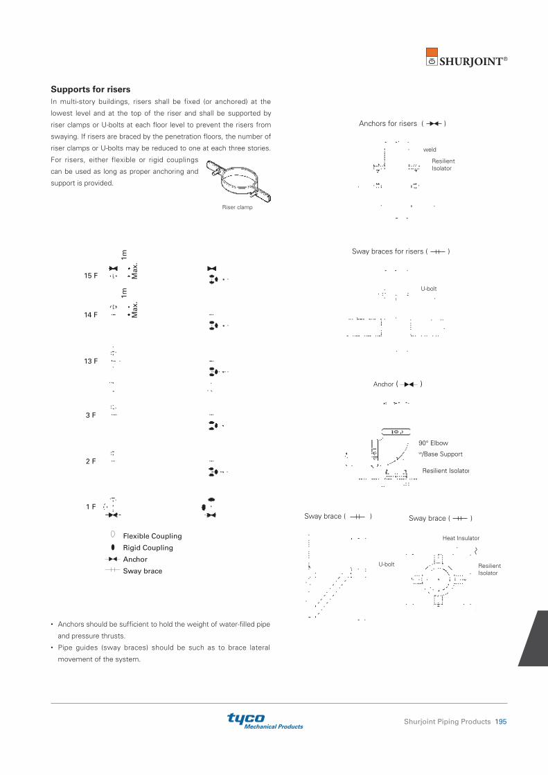
Mechanical ProductsShurjoint Piping Products 195
Supports for risersIn multi-story buildings, risers shall be fixed (or anchored) at the
lowest level and at the top of the riser and shall be supported by
riser clamps or U-bolts at each floor level to prevent the risers from
swaying. If risers are braced by the penetration floors, the number of
riser clamps or U-bolts may be reduced to one at each three stories.
For risers, either flexible or rigid couplings
can be used as long as proper anchoring and
support is provided.
• Anchors should be sufficient to hold the weight of water-filled pipe
and pressure thrusts.• Pipe guides (sway braces) should be such as to brace lateral
movement of the system.
1m
2 F
1 F
14 F
3 F
13 F
Max
.
15 F Max
.1m
Flexible Coupling
Rigid Coupling
Anchor
Sway brace
weld
Anchors for risers ( )
ResilientIsolator
Sway braces for risers ( )
U-bolt
90° Elboww/Base Support
Resilient Isolator
Anchor ( )
Sway brace ( )
Heat Insulator
ResilientIsolator
Sway brace ( )
U-bolt
Riser clamp

Mechanical Products196 Shurjoint Piping Products
Gasket Selection Guide
Over the past 50 years great advances have been made in synthetic elastomer technologies,
allowing us to offer a full range of gasket materials for a wide variety of piping applications.
Shurjoint utilizes the finest materials available in our gaskets which are engineered and designed
to meet and exceed industry standards such as ASTM D2000, AWWA C606, NSF61, IAPMO, etc.
Our continual research, development and testing all serve to advance this field and to develop
new and superior solutions for our changing industry. Selecting the proper gasket for the intended
service application requires careful consideration of many factors to assure maximum gasket life.
Those factors include temperature, fluid media and concentration, and continuity of service. The
gaskets color coding helps to identify the gasket grade and compound.
General Service Recommendations
Good for cold & hot water up to +230°F (+110°C). Also good for services for water with acid, water with chlorine, deionized water, seawater and waste water, dilute acids, oil-free air and many chemicals.Not recommended for petroleum oils, mineral oils, solvents and aromatic hydrocarbons.
Good for petroleum oils, mineral oils, vegetable oils, non-aromatic hydrocarbons, many acids and water +150°F (+65°C).
Specially compounded for cold +86°F (+30°C) and hot +180°F (+82°C) potable water services. The compound is UL classified per NSF/ANSI 61 & NSF/ANSI 372.
UL approved pre-lubricated gasket designed specifically only for the fire protection industry.
Good for oily and greasy food products and processing, as well as pharmaceutical and cosmetics manufacturing. Compounded from FDA approved ingredients (CFR Title 21 Part 177.2600).
Good for dry, hot air without hydrocarbons and some high temperature chemical services. May also be used for fire protection dry systems.
Good for hot lubricating oils and certain chemicals.
Good for many oxidizing acids, petroleum oils, halogenated hydrocarbons, lubricants, hydraulic fluids, organic liquids and air with hydrocarbons to +300°F (+149°C).
Good for aromatic fuels at low temperatures and also for ambient temperature water.
Grade
E
T
E-pw
Lube-E
A
L
V
O
M2
Maximum Temp. Range
-30°F (-34°C) to +230°F (+110°C)
-20°F (-29°C) to +180°F (+82°C)
≤+180°F (+82°C)
-30°F (-34°C) to +150°F (+65°C)
+20°F (-7°C) to +180°F (+82°C)
-30°F (-34°C) to +350°F (+177°C)
-30°F (-34°C) to +180°F (+82°C)
+20°F (-7°C) to +300°F (+149°C)
-40°F (-40°C) to +160°F (+71°C)
Color Code
Green Stripe
Orange Stripe
Double GreenStripe
Violet Stripe
White Gasket
Red Gasket
Yellow Stripe
Blue Stripe
White Stripe
Compound
EPDM
Nitrile
EPDM
EPDM
White Nitrile
Silicone
Neoprene
Fluoro-elastomer
Epichloro-hydrin
Gasket Grade Index
General Service Recommendations
Specially compounded for use with AWWA ductile iron pipe and used for petroleum products, mineral oils, vegetable oils and air with oil vapors.
Good for water services, mild dilute acids, oil-free air and many chemicals. The compound is UL classified per NSF/ANSI 61 & NSF/ANSI 372.(AWWA ductile iron pipe use)
Grade
S
M
Maximum Temp. Range
-20°F (-29°C) to +180°F (+82°C)
-20°F (-29°C) to +200°F (+93°C)
Color Code
Red Stripe
Brown Stripe
Compound
Nitrile
Haloganated Butyl
Special Gaskets for AWWA ductile iron pipe
Please note that EPDM grade "EH" gaskets can be used for all applications and services that EPDM grade "E" gaskets are suitable for.
WARNING ! Gaskets should never be exposed to temperatures outside their ratings. EPDM gaskets for water services are not compatible for steam services.
Failure to select the proper gasket and compound may result in joint leakage or failure resulting in personal injury and/or property damage. For more details and support, please contact Shurjoint.

Mechanical ProductsShurjoint Piping Products 197
Gasket Selection Guide
Proper gasket selection is essential for the optimum performance of Shurjoint grooved couplings, flange adapters and mechanical tees.
1. Gasket styles: Shurjoint grooved couplings utilize several
different gasket styles, standard, GapSeal, EP (End Protection) and
FF (Fast Fit). GapSeal gaskets are compatible with standard gaskets
and they are interchangeable with each other. Other special styles
are not compatible with standard or GapSeal gaskets. Always use
the correct gasket style for the coupling model you selected.
2. Vacuum service: Shurjoint standard gaskets are designed
to seal well under vacuum conditions up to 10 inHg (absolute)/
254 mmHg (absolute) which may occur when a system is drained.
For continuous services greater than 10 inHg (absolute)/254 mmHg
(absolute), the use of GapSeal gaskets or EP (End Protection)
gaskets in combination with rigid style couplings is recommended.
Contact Shurjoint for specific recommendations.
3. Dry pipe and freezer services: Shurjoint recommends
the use of GapSeal Grade "E" gaskets for dry pipe fire protection
systems and freezer applications. The GapSeal gasket closes off
the gap between the pipes or gasket cavity. This will prevent any
remaining liquid from entering the cavities and freezing when the
temperature drops. Rigid couplings are preferred for dry pipe,
freezer and vacuum applications. Reducing couplings are not
recommended for these applications.
NOTE: Do not use the Shurjoint standard Lubricant for dry pipe
and freezer systems, instead use a petroleum free silicone based
lubricant.
4. NSF/ANSI 61 Standard: NSF/ANSI 61 classified gaskets
are good for potable water services. The classification categories
are ‘cold’ which is limited to +86°F (+30°C) (or maximum ambient
distribution temperatures of unheated water) maximum and ‘hot’
which is limited to +180°F (+82°C) (or scalding temperatures of hot
domestic water).
5. NSF/ANSI 372 Standard: Maximum Lead
Content (formerly Annex G): Product complies with NSF/
ANSI 372 and conforms with lead content requirements for "lead
free" plumbing as defined by California, Vermont, Maryland and
Louisiana State laws and the U. S. Safe Drinking Water Act in effect
as of Jan. 4, 2014.
6. Lubricant: Shurjoint Lubricant is recommended for proper
gasket installation to prevent the gasket from being pinched. Apply a
thin coat to the gasket exterior, gasket lips and/or housing interiors.
Shurjoint Lubricant is available in one pound (450 grams) and one
quart ( 2 pounds or 900 grams) containers. Certified to NSF/ANSI 61.
Standard
GapSeal
End Protection
FastFitTM
Reducing
Outlet Coupling
Reducing(2" x 1½", 2½" x 2", 3" x 2½")
Mechanical Tee
Saddle-Let
Flange Adapter
Wildcat
AWWA Ductile Iron Pipe
HDPE Pipe
IPS to AWWA

Mechanical Products198 Shurjoint Piping Products
CHEMICAL SERVICES
Chemical Composition Gasket Grade
Acetaldehyde E
Acetamide T
Acetic Acid up to 10% 100°C (38°C) E/L
Acetic Acid up to 10-50% 100°C (38°C) L
Acetic Acid, Glacial 100°C (38°C) L
Acetic Anhydride E
Acetone E
Acetonitrile E/T
Acetophenone E
Acetylene E/T
Acrylic Resin V
Acrylonitrile NR
Adipic Acid T
Air, oil free E
Air with vapored oil T
Alkalis E
Allyl Alcohol to 96% E
Allyl Chloride NR
Alum Sulfuric Acid O
Alums E/T
Aluminum Chloride E/T
Aluminum Fluoride E/T/O
Aluminum Hydroxide E/O
Aluminum Nitrate E/T/V
Aluminum Oxychloride T
Aluminum Phosphate E
Aluminum Salts E/T
Aluminum Sulfate E/T
Alums E/T
Ammonia Anhydrous (Pure Ammonia) NR
Ammonia Gas, Cold E
Ammonia, Aqua, 10-25% E
Ammonia, Liquid E
Ammonium Alum V
Ammonium Bifluoride T
Ammonium Carbonate E
Ammonium Chloride E/T
Ammonium Fluoride E
Ammonium Hydroxide E
Ammonium Metaphosphate E
Ammonium Nitrate E/T
Ammonium Nitrite E
Ammonium Persulfate, to 10% E
Ammonium Phosphate T
Ammonium Sulfamate T
Ammonium Sulfate E/T
General Gasket Service RecommendationsThe fo l lowing are genera l serv ice
recommendations only and the information
provided is based on the best information
available from various resources including
elastomer manufacturers, leading rubber
molders, industry publications and our own
laboratory testing and field experience.
The information contained herein shall be
considered for evaluation purposes and
CHEMICAL SERVICES
Chemical Composition Gasket Grade
Ammonium Sulfide E
Ammonium Thiocyanate E
Amyl Acetate E
Amyl Alcohol E
Amyl Borate V
Amyl Chloride NR
Amyl Chloronaphthalene T
Anderol O
Aniline E
Aniline Dyes E
Aniline Hydrochloride E
Aniline Oil E
Animal Fats A
Anthraquinone NR
Anthraquinone Sulfonic Acid NR
Antimony Chloride E
Antimony Trichloride E
Argon Gas E/O
Aroclor(S) O
Arsenic Acid, to 75% E/T/O
Arylsulfonic Acid NR
ASTM #1, 2 & 3 Oil T
Barium Carbonate E
Barium Chloride E/T
Barium Hydroxide E/T
Barium Nitrate V
Barium Sulfide T
Beer A
Beet Sugar liquors A
Benzaldehyde E
Benzene O
Benzine (see Petroleum Ether) O
Benzoic Acid E
Benzol O
Benzyl Alcohol E
Benzyl Benzoate E
Benzyl Chloride E
Black Sulfate Liquor T
Blast Furnace Gas T
Bleach,12% Active Cl2 E
Borax Solutions E
Bordeaux Mixture E
Boric Acid E/T
Bromine O
Bromine Water V
Butane Gas T
not as a guarantee. When and wherever
possible, gasket materials should be
tested with simulated service conditions
to determine suitability for the intended
service application. Unless otherwise noted,
the recommendations are based on ambient
temperatures. These recommendations do
not apply to rubber lined products or rubber
sealed valves. If more than one gasket
grade is listed the preferred grade is listed
first for general services. For chemicals
not listed, a combination of chemicals
listed or not, service temperatures not
listed or borderline services, contact a
Shurjoint Engineering Representative for a
recommendation.
Note: NR = Not Recommended
CHEMICAL SERVICES
Chemical Composition Gasket Grade
Bromotoluene NR
Butanol (see Butyl Alcohol) E/T
Butter A
Butyl Acetate Ricinoleate E/T
Butyl Alcohol E/T
Butyl “Cellosolve Adipate” E/T
Butyl Phenol E
Butyl Stearate T/O
Butylene T/O
Butylene Glycol E
Butyne Diol NR
Calcium Acetate T
Calcium Bisulphite T/O
Calcium Carbonate E/T
Calcium Chlorate E/T
Calcium Chloride E/T
Calcium Hydroxide (Lime) E/T
Calcium Hypochlorite E
Calcium Hypochloride E
Calcium Nitrate E/T/V
Calcium Sulfate E/T
Calcium Sulfide E/T
Caliche Liquors T
Cane Sugar Liquors A
Carbitol E/T
Carbonic Acid, Phenol O
Carbon Bisulphide O
Carbon Dioxide, Dry E/T
Carbon Dioxide, Wet E/T
Carbon Disulphide O
Carbon Monoxide E
Carbon Tetrachloride O
Carbonic Acid, Dry O
Caster Oil T/A
Caustic Potash E/T
Cellosolve E/V
Cellosolve Acetate E
Cellosolve (Alcohol Ether) E
Cellulose Acetate E
Cellulube 220 (Tri-Aryl-Phosphate) E
Cellulube Hydraulic Fluids E
China Wood Oil, Tung Oil T
Chloric Acid to 20% E
Chlorine, Dry O
Chlorine, Water 4000 PPM (max.) E
Chlorinated Paraffin (Chlorocosane) T

Mechanical ProductsShurjoint Piping Products 199
CHEMICAL SERVICES
Chemical Composition Gasket Grade
Chloroacetic Acid E
Chloroacetone E
Chlorobenzene O
Chloralhydrate NR
Chlorobromomethane NR
Chloroform O
Chlorosulphonic Acid NR
Chrome Alum E/T
Chromic Acid, to 10% O
Chromic Acid, to 25% O
Chrome Plating Solutions O
Citric Acid, Saturated E
Citric Acid E/T
Coconut Oil A
Cod Liver Oil A
Coke Oven Gas T/O
Copper Carbonate E/T
Copper Chloride E/T
Copper Cyanide E/T
Copper Fluoride E
Copper Nitrate E/T
Copper Sulfate E/T
Corn Oil A
Cotton Seed Oil A
Creosol, Cresylic Acid O
Creosote, Coal Tar T/O
Creosote, Wood T/O
Cupric Fluoride E/T
Cupric Sulfate E/T
Cyclohexane (Alicyclic Hydrocarbon) O
Cyclohexanol V/O
Cyclohexanone E
Deionized Water E
Dextrim T
Diacetone Alcohol V
Dibutyl Phthalate E
Dichloro Difloro Methane T
Dicyclohexylamine T
Diesel Oil T
Diethyl Ether T
Diethyl Sebacate E
Diethylamine T
Diethylene Glycol E/T
Digester Gas T
Dimethylamine T
Dioctyl Phthalate E
Dioxane E
Dipentene(Terpene-Hydrocarbon) T
Dipropylene Glycol T
Dowtherm A O
Dowtherm E O
Dowtherm SR-1 T/E
Ethane E
Ethanolamine E
Ethers NR
Ethyl Acetoacetate E
Ethyl Acrylate L
Ethyl Alcohol (Ethanol) E
Ethyl Cellulose E
CHEMICAL SERVICES
Chemical Composition Gasket Grade
Ethyl “Cellusolve” E
Ethyl Chloride E/T
Ethyl Ether T
Ethyl Oxalate E
Ethyl Silicate T
Ethylene Chlorohydrin E
Ethylene Diamine E/T
Ethylene Dichloride (Dichloroethane) O
Ethylene Glycol E/T
Ethylene Oxide NR
Fatty Acid A
Ferric Chloride, to 35% E/T/O
Ferric Chloride, Saturated E
Ferrous Nitrate V
Ferric Hydroxide E
Ferric Sulfate T
Fish Oils (Solubles) A
Fire Fighting Foam Concentrate E/O
Fluboric Acid E/T
Fluorine Gas, Wet NR
Fluorosilicic Acid, to 30% V
Fly Ash E
FM200 HFC-227ea E
Foam E
Fog Oil T
Formaldehyde E/T
Formamide E/T
Formic Acid, to 25% E
Freon 11, 130°F (54°C) T
Freon 12, 130°F (54°C) T
Freon 113 130°F (54°C) T
Freon 114,130°F (54°C) T
Freon F-12 T
Freon 123 NR
Freon 134a,176° (80°C) E/T
Freon F-21 NR
Freon 22, 130°F (54°C) V
Fructose E/T
Fuel Oil T
Fumaric Acid E
Furan NR
Furfuryl Alcohol E
Gallic Acid NR
Gasoline, Refined T
Gasoline, Refined, Unleaded O
Gelatin A
Glucose A
Glue E/T
Glycerin E/T
Glycerol E/T
Glycol E/T
Glycolic Acid E
Grease T/V/O
Green Sulfate Liquor T
Halon 1301 E
Heptane T
Hexaldehyde E
Hexane T
Hexanol V/T
CHEMICAL SERVICES
Chemical Composition Gasket Grade
Hexanol Tertiary T
Hexyl Alcohol V/T
Hexylene Glycol T
Hydrobromic Acid, to 40% E
Hydrochloric Acid, to 36%, 75°F (24°C) E
Hydrochloric Acid, to 36%, 158°F (70°C) O
Hydrocyanic Acid E
Hydrofluoric Acid, to 75%, 75°F (24°C) O
Hydrofluosilicic Acid E
Hydrocyanic Acid, to 10% E
Hydrofluoric Acid, to 30% V/O
Hydrofluosilicic Acid, to 50% T
Hydrogen Phosphide NR
Hydrogen Gas, Cold E/T
Hydrogen Gas, Hot E
Hydrogen Peroxide, to 50% L
Hydrogen Peroxide, to 90% O
Hydrogen Sulfide E
Hydroquinone T/O
Hydroxylamine Sulfate E
Hypochlorous Acid, Dilute E
Isododecane V
Isobutyl Alcohol E
Iso Octane, 100°F (38°C) T
Isopropyl Acetate E
Isopropyl Ether T
JP-3 T
JP-4 T/O
JP-5 T/O
JP-6, 7, 8 T
Kerosene T
Ketones E
Lactic Acid A
Lard Oil V
Latex (1% Styrene & Butadiene) O
Lauric Acid T
Lauryl Chloride NR
Lavender Oil T
Lead Acetate T
Lead Chloride E
Lead Sulfamate V
Lead Sulfate T
Lime and H2O E/T
Lime Sulfur O
Linoleic Acid O
Lithium Bromide T
Lithium Bromide (Brine) T/O
Linseed Oil A
Lithium Chloride T/O
Lubricating Oil, Refined T
Lubricating Oil, Sour T
Lubricating Oil, to 150°F (66°C) T
Lubricating Oil, 150°F (66°C) V/T
to 180°F (82°C)
Magnesium Chloride E/T
Magnesium Hydroxide E/T
Magnesium Nitrate E/V
Magnesium Sulfate E/T
Maleic Acid, Saturate T

Mechanical Products200 Shurjoint Piping Products
CHEMICAL SERVICES
Chemical Composition Gasket Grade
Malic Acid T
Mercuric Chloride E/T
Mercuric Cyanide E/T
Mercurous Nitrate E/T
Mercury E/T
Methane T
Methyl Acetate V
Methyl Alcohol, Methanol E/T
Methyl Cellosolve (Ether) V
Methyl Chloride O
Methyl Ethyl Ketone NR
Methyl Isobutyl Carbinol E
Methylene Chloride O
Methylene Chlorobromide NR
Methylene Dichloride 100°F (38°C) O
MIL-L7808 O
MIL-05606 O
MIL-08515 O
Milk A
Mineral Oils T
Naphta O
Naohtalene NR
Naptha, 160°F (71°C) O
Napthenic Acid T
Natural Gas T
Nevoil E
Nickel Acetate to 10%, 100°F (38°C) V
Nickel mmonium Sulfate V
Nickel Chloride E/T
Nickel Nitrate V
Nickel Plating Solution E/T
125°F (52°C) - Max.
Nickel Sulfate E/T
Nitric Acid to 10%, 75°F (24°C) - Max. E
Nitric Acid, 10-50%, 75°F (24°C) - Max. O
Nitric Acid, 50-86%, 75°F (24°C) O
Nitric Acid, Red Fuming O
Nitrocellulose V
Nitrogen E
Nitromethane E
Nitrous Oxide E
NOVEC 1230 FK-5-1-12 E
Octyl Alcohol VOgisogiric Acid, O
to 75%, 150°F (66°C)
Oil, Crude Sour T
Oil, Motor T
Oleic Acid T
Oilve Oil T/A
Oronite 8200 Silicate Ester Fluid O
Orthodichlorobenzene O
OS-45 Silicate Ester Fluid O
OS-45-1 O
Oxalic Acid E
Oxygen, Cold E
Ozone (100 ppm) E
Palm Oil T/A
Peanut Oil A
Palmitic Acid T
Pentane T
CHEMICAL SERVICES
Chemical Composition Gasket Grade
Perchloric Acid NR
Perchloroethylene O
Petroleum Ether (see Benzene) O
Petroleum Oils T
Phenol (Carbolic Acid) O
Phenylhydrazine E
Phenylhydrazine Hydrochloride E
Phosphate Ester E
Phosphoric Acid, to 50% E
Phosphoric Acid, to 75% and 70°F E/T
Phosphoric Acid, to 85%, O
150°F (66°C) - Max.
Phosphate Ester E
Photographic Solutions T
Phthalic Anhydride E
Picric Acid V
Plating Solutions, (gold, brass V
cadmium, copper, lead, silver, tin, zinc)
Polybutene T
Polyvinyl Acetate, Solid
(In Liquid State is 50% solution E
of Methanol or 60% solution of H2O)
Potash E
Potassium Alum E/T
Potassium Aluminum Sulfate E/T
Potassium Bicarbonate E/T
Potassium Bichromate E/T
Potassium Borate E
Potassium Bromate E
Potassium Bromide E/T
Potassium Carbonate E/T
Potassium Chlorate E
Potassium Chloride E/T
Potassium Chromate T
Potassium Cyanide E/T
Potassium Dichromate E
Potassium Ferricyanide E
Potassium Ferrocyanide E
Potassium Fluoride E
Potassium Hydroxide T
Potassium Iodide V
Potassium Nitrate E/T
Potassium Perborate E
Potassium Perchlorate T
Potassium Permanganate, E
Saturated to 10%
Potassium Permaganate E
Saturate 10-25%
Potassium Persulfate T
Potassium Silicate E/T/V
Potassium Sulfate E/T
Prestone T
Propane Gas T
Propanol E/T
Propargyl Alcohol E
Propyl Alcohol E/T
Propylene Dichloride L
Propylene Glycol E
Pydraul F-9 and F-150 NR
CHEMICAL SERVICES
Chemical Composition Gasket Grade
Pyranol 1467 T
Pyranol 1476 T
Pyroguard “C” T
Pyroguard “D” T
Pyroguard 55 E
Pyrrole E
Ref. Fuel (70 ISO Octane, 30 Toluene) T
Rapeseed Oil A
Rosin Oil T/V
Salicylic Acid E
Secondary Butyl Alcohol T
Sewage E/T
Silver Nitrate E
Silver Sulfate E
Skydrol, 200°F (93°C) - Max. L
Skydrol 500 Phosphate Ester E
Soap Solutions E/T
Soda Ash, Sodium Carbonate E/T
Sodium Acetate E
Sodium Alum T
Sodium Benzoate E/T
Sodium Bicarbonate E/T
Sodium Bisulfate E/T
Sodium Bisulfite (Black Liquor) E/T
Sodium Bromide E/T
Sodium Carbonate E/T
Sodium Chlorate E
Sodium Chloride E/T
Sodium Cyanide E/T
Sodium Dichromate, to 20% E/T
Sodium Ferricyanide E/T
Sodium Ferrocyanide E/T
Sodium Fluoride E/T
Sodium Hydroxide, to 15% E
Sodium Hydro Sulfide T
Sodium Hydroxide to 50% E
Sodium Hypochlorite, to 20% E
Sodium Metaphosphate T
Sodium Nitrate E
Sodium Nitrite E/T
Sodium Perborate E
Sodium Peroxide E
Sodium Phosphate T
Sodium Phosphate, Dibasic T
Sodium Phosphate, Monobasic T
Sodium Phosphate, Tribasic T
Sodium Silicate T
Sodium Sulfate E/T
Sodium Sulfide E/T
Sodium Sulfite Solution, to 20% T
Sodium Thiosulfate, “Hypo” T
Sohovis 47 T
Sohovis 78 T
Solvasol #1 T
Solvasol #2 T
Solvasol #3 T
Solvasol #73 T
Solvasol #74 NR
Soybean Oil A

Mechanical ProductsShurjoint Piping Products 201
CHEMICAL SERVICES
Chemical Composition Gasket Grade
Spindle Oil T
Stannic Chloride T
Stannous Chloride, to 15% T
Starch E/T
Steam NR
Stearic Acid T
Stoddard Solvent T
Styrene O
Sulfonic Acid E
Sulphite Acid Liquor E
Sucrose Solutions A
Sulfur E/V
Sulfur Chloride O
Sulfur Dioxide, Dry E
Sulfur Dioxide, Wet E
Sulfur Trioxide, Dry O
Sulfuric Acid, to 25%, 150°F (66°C) E
Sulfuric Acid, 25-50%, 200°F (93°C) O
Sulfuric Acid, 50-95%, 150°F (66°C) O
Sulfuric Acid, Fuming O
Sulfuric Acid, Oleum O
Sulfurous Acid O
Tall Oil T
Tannic Acid, all conc. Tanning Liquors V
(50g. alum. solution, 50g.
dichromate solution) T
Tartaric Acid E
Tertiary Butyl Alcohol E/T
Tetrabutyl Titanate E
Tetrachloroethylene O
Thionyl Chloride T
Terpineol V
Tertiary Butyl Alcohol E/T/V
Tetrachloroethylene O
Tetrahydrofuran NR
Tetralin NR
Thiopene NR
Titanium Tetrachloride O
Toluene, to 30% T
Transmission Fluid, Type A O
Triacetin T
Trichloroethane O
Trichloroethylene O
Trichloroethylene, to 200°F (93°C) O
Tricresyl Phosphate E
Triethanolamine E/T
Trisodium Phosphate E
Tung Oil T
Turbo Oil #15 Diester Lubricant O
Turpentine T
Urea T/E
Vegetable Oils T/A
Vinyl Acetate E
Vinegar A
Vinyl Chloride O
Vi-Pex T
Water, to 150°F (66°C) E/T/M/S
Water, to 200°F (93°C) E/M
Water, to 230°F (110°C) E
CHEMICAL SERVICES
Chemical Composition Gasket Grade
Water, to 250°F (121°C) EH
Water, Acid Mine E/T
Water, Bromine O
Water, Chlorinated, to 3500 ppm E
Water, Chlorine E
Water, Deionized E/M
Water, Potable E-pw
Water, Seawater E
Water, Waste E/T/M/S
Whiskey A
White Liquor E
Wood Oil T
Xylene O
Zinc Chloride, to 50% E
Zinc Nitrate E
Zinc Sulfate E/T

Mechanical Products202 Shurjoint Piping Products
The Shurjoint fire protection series numbers over 600 individual components, including grooved couplings, fittings, flanges, mechanical tees, valves, welding outlets, threaded fittings and more. Applicable products are listed and or approved by various domestic and international approval bodies including UL, FM, VdS, LPCB and others.
Hydrostatic Tests Approved products
are rated in cold water pressure (CWP)
tested with a 3 to 5 times test pressure
depending on the approval body and pipe
size. The minimum working pressure (CWP)
shall be 175 psi (12.3 Bar) in accordance
with NFPA 13. Approval testing of a
coupling is conducted on all different pipe
schedules as enrolled and approved working
pressures (CWP) are assigned to each
individual combination of the coupling and
test pipe. Refer to the Approved Pressure
Ratings by UL and FM.
Bending Moment Tests The
required bending moment per UL and FM
is calculated based on twice the weight of
water filled pipe over twice the maximum
distance between pipe supports as
specified in NFPA 13.
See the table below for the bending
moments per UL and FM on Sch. 40 pipe.
This bending moment is twice that required
by ASTM F1476 (refer to page 15).
In addition to the hydrostatic and bending
moment tests, couplings must meet other
requirements including gasket performance
tests.
Flexible Coupling NFPA 13 defines
a flexible coupling as “a listed coupling
or fitting that allows axial displacement,
rotation, and at least 1 degree of angular
movement of the pipe without inducing
harm on the pipe. For pipe diameters of 8 in.
and larger, the angular movement shall be
permitted to be less than 1 degree but not
less than 0.5 degrees.” (NFPA 13 - 2007
3.5.4)
For sprinkler systems, NFPA 13 specifies
the use of flexible couplings to protect the
system against damage from earthquakes
and lists some specific examples of how
and where they should be used. Designers
and installers should design their fire
protection systems in compliance with this
standard. See Typical Applications – Flexible
Couplings on Page 191.
Nom. UL FM Size Moment Moment Moment Moment (inches) Nm Lbs-Ft Nm Lbs-Ft 1½ 1098 810 1100 810 2 1559 1150 1560 1150 2½ 2400 1770 2400 1770 3 3289 2426 3290 2425 4 4942 3645 4975 3670 5 7102 5238 7105 5240 6 9606 7085 9615 7090 8 15326 11304 15335 11310 10 22757 16785 22790 16805 12 31116 22950 31145 22970 14 37217 27450 16 48597 35843
Required Bending Moment by UL & FM
Nom. Size UL FM VdS LPCB
Up to 6” / 150 X5 X4 X4 X4 8” – 12” / 200 -300 X4 X4 X4 X4 14” and above X3 X4 NA NA
Hydrostatic Test Pressures(= multiple of CWP)
Contact Shurjoint for other approvals.
Water FilledSchedule 40 Steel
Sprinkler Pipe
Lhs = 15 ft Lhs = 15 ft
Pipe
CappedEnd
Test Joint
CappedEnd
Minimum OverallLength 2 ft (610 mm)
Pipe
CappedEnd
Test JointForce, F40 Capped
End
Support Spacing, LS
Minimum Pipe Schedules Standard
cut and roll grooving connections have
limitations of minimum pipe schedules.
Special care is required for thin wall pipe.
Factory Mutual Research Group (FM)
outlines the minimum pipe schedules to be
used for cut and roll grooving in their FM
Class 1920 standard as follows:
Nominal Pipe Grooving Minimum Size, in. Method Pipe Schedule
6 or smaller Cut Schedule 40
8 or larger Cut Schedule 30
2 or smaller Rolled Schedule 5
6 or smaller Rolled Schedule 10,
Thinwall, Lightwall
8 or larger Rolled 0.188 in. (4.8 mm) wall
(FM Class 1920 -2007, Table 3.2.2)
Fire Protection Services

Mechanical ProductsShurjoint Piping Products 203
1. Approved grooved couplings and fittings are good for use in both
wet and dry sprinkler systems.
2. Typical applications of flexible couplings (models 7705, 7706
& 7707) are in sprinkler risers, in feed mains passing through
walls from one building area to another, in locations subject to
earthquakes, in the discharge line from aboveground pump suction
tanks, in new connections to existing feed mains and in air or
water fire service lines subject to excessive vibration or difficult
alignment.
3. Approved grooved couplings are limited to use with rolled or cut-
groove ended pipe, valves and fittings at a minimum rated working
pressure of 175 psi (1205 kPa) and are suitable for aboveground
service.
4. Grooves should be processed according to ANSI/AWWA C606
(latest edition) Grooved and Shouldered Joints.
5. Installation must be made according to the manufacturer’s
instructions and requirements.
6. Approved grooved couplings may be used in underground service
subject to the installation restrictions placed upon the pipe and to
the coupling manufacturer’s recommendations and requirements.
7. Approved grooved couplings have been evaluated for a maximum
ambient temperature of 225°F (107°C), suitable for normal
warehouse protection.
8. Threaded size of sprinkler piping is limited to 1 inch (25 mm)
nominal.
9. Threaded connections can be made to approved threadable
thinwall pipe or to Schedule 40 pipe.
Source: FM Approval Guide
• For pressure ratings for special pipes, DIN and JIS pipe sizes, and large diameter sizes 14” – 24”, contact Shurjoint for details.
• Models K-9 and 7771 rigid couplings are also available. For pressure ratings, contact Shurjoint for details.
Approved Pressure Ratings by UL & FM
Couplings and Flange Adapters Sch. 40 & STD Wall Pipe Unit: psi
Size Wall 7705 K-9 7707 7771 Z05 Z07 7041 7043 7706 in in UL FM UL FM UL FM UL FM UL FM UL FM UL FM UL FM Size (in) UL FM ¾ 0.113 - - - - 500 - - - - - - - - - - - 2 x 1½ 300 300 1 0.133 300 300 - - 500 - - - - - - 500 - - - - 2½ x 2 300 300 1¼ 0.140 300 300 300 300 500 - - - 350 350 500 500 - - - - 3 x 2 300 300 1½ 0.145 300 300 300 300 - 500 - 500 350 350 500 500 - - - - 3 x 2½ 300 300 2 0.154 300 300 300 300 500 500 300 300 350 350 500 500 175 300 300 300 4 x 2 300 300 2½ 0.203 300 300 300 300 500 500 300 300 350 350 500 500 175 300 300 300 4 x 2½ 300 300 3 0.216 300 300 300 300 500 500 300 300 350 350 500 500 175 300 300 300 4 x 3 300 300 4 0.237 300 300 300 300 500 500 300 300 350 350 500 500 175 300 300 300 6 x 3 300 300 5 0.258 300 300 300 300 500 500 300 300 350 350 400 400 175 300 300 300 6 x 4 300 300 6 0.280 300 300 300 300 500 500 300 300 350 350 400 400 175 300 300 300 8 x 6 300 300 8 0.322 300 300 300 300 500 500 300 300 350 350 400 400 175 300 300 300 - - - 10 0.375 175^ 250 - - 300 500 175 200 - - 350 350 175 175 300 300 - - - 12 0.375 175* 250 - - 300 300 175 300 - - 350 350 175*. 175 300 300 - - -
^0.188" wall, *0.330 wall
Unit: psi
Size Wall 7705H in in UL FM 8 0.322 450 450
Unit: psi
Size Wall 7705 K-9 7707 7771 Z05 Z07 7041 7043 7706 in in UL FM UL FM UL FM UL FM UL FM UL FM UL FM UL FM Size (in) UL FM ¾ 0.083 - - - - 500 - - - - - - - - - - - 2 x 1½ 300 300 1 0.109 300 300 - - 500 - - - - - - 500 - - - - 2½ x 2 300 300 1¼ 0.109 300 300 300 300 500 - - - 350 350 500 500 - - - - 76.1 x 2 300 300 1½ 1.109 300 300 300 300 - - - 500 350 350 500 500 - - - - 3 x 2 300 300 2 0.110 300 300 300 300 450 450 300 300 350 350 500 500 175 300 300 300 3 x 2½ 300 300 2½ 0.120 300 300 300 300 450 450 300 300 350 350 500 500 175 300 300 300 3 x 76.1 300 300 76.1 0.142 300 300 300 - 500 500 - 300 300 - - - 175 - - - 4 x 2 300 300 3 0.120 300 300 300 300 450 450 300 300 350 350 500 500 175 300 300 300 4 x 2½ 300 300 4 0.120 300 300 300 300 450 450 300 300 350 350 500 500 175 300 300 300 4 x 76.1 300 300 5 0.134 300 300 300 300 450 450 300 300 350 350 400 400 175 300 300 300 4 x 3 300 300 139.7 0.197 300 300 300 - 500 500 - 300 - - - - 175 - - - 6 x 3 300 300 6 0.134 300 300 300 300 450 450 300 300 350 350 400 400 175 300 300 300 165.1 x 3 - 300 165.1 0.197 300 300 300 - 500 500 - 300 - - - - 175 - - - 6 x 4 300 300 8 0.188 300 300 300 300 450 450 300 300 350 350 400 400 175 300 300 300 165.1 x 4 300 300 10 0.188 175 175 - - 300 450 175 200 NA NA 350 350 175 175 300 300 8 x 6 300 300 12 0.250 175* 175 - - 300 300 175 300 NA NA 350 350 175* 175 300 300 8 x 165.1 - 300
Sch. 10 & BS 1387 Medium Pipe
* 0.330 wall
Unit: psi
Size Wall 7705H in in UL FM 8 0.188 450 450

Mechanical Products204 Shurjoint Piping Products
Grooved-end Fittings Model Size Range UL FM 901 S/R 90 Elbow 2" thru 8" 300 300
903 S/R Tee 2" thru 8" 300 300
76.1, 165.1 300 - 1" thru 8" 300 500
7110 90 Elbow 10", 12" 300 300
14" thru 18" 300 175 24" - 175 1" - 500 1¼" thru 8" 300 500
7111 45 Elbow 10", 12" 300 300
14" thru 18" 300 175 20" 250 250 24" 250 175 7110DR Drain Elbow 2" thru 6" 300 300 7110LR 1.5D Elbow 2" thru 8" 300 300 1¼" - 300 7112 22½ Elbow 1½" 500 300 2" thru 8" 300 300
7113 11¼ Elbow 1¼" thru 1½" - 300
2" thru 8" 300 300 1¼" thru 8" 300 500 7120 Tee 10" thru 14" 300 300 18" 300 -
7121 Reducing Tee 2"x1½" thru 8"x6" 300 300
12"x10" 300 -
7125 Bullhead Tee 2"x2½" thru 4"x6" 300 300
5"x8" thru 6"x8" 300 -
7127 Standpipe Tee 4"x2½" 300 300
6x2½" 300 - 7130 Lateral 2" thru 8" 300 300
7135 Cross 2" thru 6" 300 300
8" 300 -
7150 Conc. Reducer 2"x1½" thru 14"x12" 300 300
16"x8" thru 18"x16" 300 -
7150F Socket Adapter 1½"x1" thru 4"x2½" 300 300
5"x1½" thru 6"x4" 300 - 7150M Red. Nipple 1½"x1" thru 6"x4" 300 300 7160T Transition Fitting 2"x1" thru 6"x2" 300 300
7151 Ecc. Reducer 2½"x2" thru 8"x6" 300 300
10"x8" thru 14"x12" - 300 7160 End Cap 1¼" thru 12" 300 300 10" thru 12" 300 300 7160H End Cap 14" thru 18" 300 175 20" thru 24"* 250 175 7170 Flange Adapter 2-1/2" thru 6" 175 175 7180 Flange Adapter 2" thru 8" 300 300 7181 Red. Flange 3"x2" thru 6"x4" - 300 55 Nipple Adapter 1½" thru 2" 300 300 899 End All 1¼"x½" thru 2½"x1" 300 300 850 Sprinkler Hub 2"x2"x1" thru 2½"x2½"x1" 300 300 851 Sprinkler Hub 2"x1½"x1" thru 2½"x2x1" 300 300 853 Sprinkler Hub 1½"x1" thru 2½"x1" 300 300
Unit: psi
* 20" only for UL
Approved Pressure Ratings by UL & FMOutlet Coupling and Mechanical Tees Sizes (in) Sch. 40/STD Sch. 10 Model (run x branch) UL FM UL FM 1½ x ½, ¾ & 1 300 300 300 300 2 x ½, ¾ & 1 300 300 300 300 2½ x ½, ¾ & 1 300 300 300 300 3 x ¾ & 1 300 300 300 300 4 x ¾ & 1 300 300 300 300 6 x 1 & 1½ 300 300 300 300 2 x 1 300 300 300 300 2½ x 1¼ & 1½ 300 300 300 300 3 x 1 & 1½ 300 300 300 300 4 x 1½ & 2 300 300 300 300 6 x 1½ & 2 300 300 300 300 2 x ½, ¾, 1, 1¼ & 1½ 300 300 300 300 2½ x ½, ¾, 1, 1¼ & 1½ 300 300 300 300 76.1 x ½, ¾, 1, 1¼ & 1½ 300 300 300 300 3 x ½, ¾, 1, 1¼, 1½ & 2 300 300 300 300 4 x ½, ¾, 1, 1¼, 1½, 2 & 2½ 300 300 300 300 4 x 76.1 300 300 300 300 4 x 3 175 175 175 175 5 x 2 & 2½ 300 300 - 300 5 x 3 300 - - - 139.7 x 2, 76.1 & 3 300 300 300 300 6 x 1¼, 1½, 2 & 2½ 300 300 300 300 6 x 3 & 4 175 175 175 175 165.1 x 1¼, 1½ , 2 & 76.1 300 300 300 300 165.1 x 3 & 4 175 175 175 175 2 x 1, 1¼ & 1½ 300 300 300 300 2½ x 1, 1¼ & 1½ 300 300 300 300 76.1 x 1, 1¼ & 1½ 300 300 300 300 3 x 1, 1¼, 1½ & 2 300 300 300 300 4 x 1, 1¼, 1½, 2 & 2½ 300 300 300 300 4 x 76.1 300 300 300 300 5 x 2 & 2½ 300 300 300 300 4 x 3 175 175 175 175 139.7 x 76.1 300 300 300 300 6 x 1¼, 1½, 2 & 2½ 300 300 300 300 6 x 3 & 4 175 175 175 175 165.1 x 1¼, 1½, 2 & 76.1 300 300 300 300 165.1 x 3 & 4 175 175 175 175 4 x 3 300 300 300 300 8 x 2, 2½, 3 & 4 300 300 300 300 8 x 76.1 300 300 300 300 4 x 3 300 300 300 300 8 x 2, 2½, 3 & 4 300 300 300 300 8 x 76.1 300 300 300 300 1¼ x ½ x ¾ & 1 300 300 300 300 1½ x ½ x ¾ & 1 300 300 300 300 2 x ½ x ¾ & 1 300 300 300 300 2½ x ½ x ¾ & 1 300 300 300 300
C-7 Outlet Coupling, Threaded
C-7 Outlet Coupling, Grooved
M21 Mechanical
Tee, Threaded (NPT or BSPT)
M22 Mechanical
Tee, Grooved
7721 Threaded (NPT or BSPT)
7722 Grooved
723 Threaded (NPT or BSPT)
Unit: psi
mm size pipe per EN 10255
Size Sch. 10S SS-7 SS-8 SS-41 SS-723 in Wall (in) UL FM UL FM UL FM Size (in) UL FM 1 0.109 300 300 300 300 - - 1¼ x ½ 300 300 1¼ 0.109 300 300 300 300 - - 1¼ x ¾ 300 300 1½ 0.109 300 300 300 300 - - 1¼ x 1 300 300 2 0.109 300 300 300 300 175 300 1½ x ½ 300 300 2½ 0.120 300 300 300 300 175 300 1½ x ¾ 300 300 3 0.120 300 300 300 300 175 300 1½ x 1 300 300 4 0.120 300 300 300 300 175 300 2 x ½ 300 300 5 0.134 300 300 300 300 - - 2 x ¾ 300 300 6 0.134 300 300 250 300 175 300 2 x 1 300 300 8 0.148 300 300 - 300 - -
Stainless Steel SeriesSch. 40S and 10S Pipe Unit: psi
Model Size Range UL FM SS-10 90 Elbow 1" thru 8" 300 300 SS-11 45 Elbow 1" thru 8" 300 300 SS-20 Tee 1" thru 6" 300 300 SS-21 Tee 3"x2½" thru 4"x2½" 300 300 SS-21F Tee 3"x2", 4"x2" 300 300 SS-50 Conc. Reducer 3"x2½" thru 4"x2½" 300 300 SS-50F Conc. Reducer 2½"x2" thru 4"x2" 300 300 SS-60 Cap 1" thru 8" 300 300 SS-80 Flange Adapter 2" thru 8" 300 300
Unit: psi
Model Size Range UL FM RCV Riser Check Valve 2½" thru 6" 300 300
726 Y-Straine 2" thru 6" 300 -
8" thru 12" 175 -
SJ-300F Butterfly Valve 2½" thru 6" 300 300
8" 300 -
Unit: psiValves & Components

Mechanical ProductsShurjoint Piping Products 205
Size Type K Type L C341 in Wall (in) Wall (in) UL FM 2 0.083 0.070 200 - 2½ 0.095 0.080 200 - 3 0.109 0.090 200 - 4 0.134 0.110 200 - 5 0.160 0.123 200 - 6 0.192 0.140 200 -
Copper Tubing Series Type K & Type L Copper Tubing
FM: Type K only
Unit: psi
Model Size Range UL FM C10 90 Elbow 2" through 4" 175 200 C11 45 Elbow 2" through 4" 175 200 C20 Tee 2" through 6" 175 200 C21 Reducing Tee 2½"x2" thrru 6"x5" 200 - C26 Reducing Tee 2"x¾" thru 4"x½" 200 - C50 Conc. Reducer 2½"x2" thru 6"x5" 200 - C52 Conc. Reducer 2"x1" thru 4"x2" 200 - C60 Cap 2" thru 4" 200 200
Unit: psi
The following tables show Shurjoint
Couplings used on carbon steel, stainless
Listed Pressure Ratings by IAPMO
Model Z05 Rigid Coupling
Model 7706 Reducing Coupling
Model Z07 Rigid Coupling Model 7705 Flexible Coupling Nom. Pipe Pressure Min. Size O.D. Ratings Wall in in PSI Roll (mm) mm mm Bar Cut (mm) 1¼ 1.660 350 1.7 32 42.2 24 3.6 1½ 1.900 350 1.7 40 48.3 24 3.7 2 2.375 350 1.7 50 60.3 24 3.9 2½ 2.875 350 2.1 65 73.0 24 4.8 3 3.500 350 2.1 80 88.9 24 4.8 4 4.500 350 2.1 100 114.3 24 5.2 5 5.563 350 2.8 125 141.3 24 5.2 6 6.625 350 2.8 150 168.3 24 5.6 8 8.625 350 2.8 200 219.1 24 6.1
Nom. Pipe Pressure Min. Size O.D. Ratings Wall in in PSI Roll (mm) mm mm Bar Cut (mm) 2½x2 2.875x2.375 300 2.1x1.7 65x50 73.0x60.3 20 4.8x3.9 3x2 3.500x2.375 300 2.1x1.7 80x50 88.9x60.3 20 4.8x3.9 3x2½ 3.500x2.875 300 2.1x2.1 80x65 88.9x73.0 20 4.8x4.8 4x2½ 4.500x2.875 300 2.1x2.1 100x65 114.3x73.0 20 5.2x4.8 4x3 4.500x3.500 300 2.1x2.1 100x80 114.3x88.9 20 5.2x4.8 5x4 5.563x4.500 300 2.8x2.1 125x100 141.3x114.3 20 5.2x5.2 6x4 6.625x4.500 300 2.8x2.1 150x100 168.3x114.3 20 5.6x5.2 8x6 8.625x6.625 300 2.8x2.8 200x150 219.1x168.3 20 6.1x5.6
Nom. Pipe Pressure Min. Size O.D. Ratings Wall in in PSI Roll (mm) mm mm Bar Cut (mm) 1¼ 1.660 500 1.7 32 42.2 35 3.6 1½ 1.900 500 1.7 40 48.3 35 3.7 2 2.375 500 1.7 50 60.3 35 3.9 2½ 2.875 500 2.1 65 73.0 35 4.8 3 3.500 500 2.1 80 88.9 35 4.8 4 4.500 500 2.1 100 114.3 35 5.2 5 5.563 400 2.8 125 141.3 28 5.2 6 6.625 400 2.8 150 168.3 28 5.6 8 8.625 400 2.8 200 219.1 28 6.1 10 10.750 350 3.4 250 273.0 24 6.4 12 12.750 350 4.0 300 323.9 24 7.1
Nom. Pipe Pressure Min. Size O.D. Ratings Wall in in PSI Roll (mm) mm mm Bar Cut (mm) 1¼ 1.660 300 1.7 32 42.2 20 3.6 1½ 1.900 300 1.7 40 48.3 20 3.7 2 2.375 300 1.7 50 60.3 20 3.9 2½ 2.875 300 2.1 65 73.0 20 4.8 3 3.500 300 2.1 80 88.9 20 4.8 4 4.500 300 2.1 100 114.3 20 5.2 5 5.563 300 2.8 125 141.3 20 5.2 6 6.625 300 2.8 150 168.3 20 5.6 8 8.625 300 2.8 200 219.1 20 6.1 10 10.750 175 3.4 250 273.0 12 6.4 12 12.750 175 4.0 300 323.9 12 7.1
Model 7707 Rigid Coupling Nom. Pipe Pressure Min. Size O.D. Ratings Wall in in PSI Roll (mm) mm mm Bar Cut (mm) 1¼ 1.660 500 1.7 32 42.2 35 3.6 1½ 1.900 500 1.7 40 48.3 35 3.7 2 2.375 450 1.7 50 60.3 31 3.9 2½ 2.875 450 2.1 65 73.0 31 4.8 3 3.500 450 2.1 80 88.9 31 4.8 4 4.500 450 2.1 100 114.3 31 5.2 5 5.563 450 2.8 125 141.3 31 5.2 6 6.625 450 2.8 150 168.3 31 5.6 8 8.625 450 2.8 200 219.1 31 6.1 10 10.750 450 3.4 250 273.0 31 6.4 12 12.750 300 4.0 300 323.9 20 7.1
steel pipe, and copper tubing; listed by
IAPMO in accordance with CSA B242.

Mechanical Products206 Shurjoint Piping Products
Model SS-5 Rigid Coupling Model SS-7 Rigid Coupling Model C305 Rigid Coupling
Model C306 Reducing Coupling Model C307 Transition Coupling
Nom. Pipe Pressure Min. Size O.D. Ratings Wall in in PSI Roll (mm) mm mm Bar Cut (mm) 1¼ 1.660 300 1.7 32 42.2 20 3.6 1½ 1.900 300 1.7 40 48.3 20 3.7 2 2.375 300 1.7 50 60.3 20 3.9 2½ 2.875 300 2.1 65 73.0 20 4.8 3 3.500 300 2.1 80 88.9 20 4.8 4 4.500 300 2.1 100 114.3 20 5.2 5 5.563 300 2.8 125 141.3 20 5.2 6 6.625 300 2.8 150 168.3 20 5.6 8 8.625 300 2.8 200 219.1 20 6.1
Nom. Pipe Pressure Min. Size O.D. Ratings Wall in in PSI Roll (mm) mm mm Bar Cut (mm) 1¼ 1.660 300 1.7 32 42.2 20 3.6 1½ 1.900 300 1.7 40 48.3 20 3.7 2 2.375 300 1.7 50 60.3 20 3.9 2½ 2.875 300 2.1 65 73.0 20 4.8 3 3.500 300 2.1 80 88.9 20 4.8 4 4.500 300 2.1 100 114.3 20 5.2 5 5.563 300 2.8 125 141.3 20 5.2 6 6.625 300 2.8 150 168.3 20 5.6 8 8.625 300 2.8 200 219.1 20 6.1
Nom. Pipe Pressure Min. Size O.D. Ratings Wall in in PSI
Roll (mm) mm mm Bar 2 2.125 300
1.1 50 54.0 20 2½ 2.625 300
1.1 65 66.7 20 3 3.125 300
1.1 80 79.4 20 4 4.125 300
1.5 100 104.8 20 5 5.125 300
1.8 125 130.2 20 6 6.125 300
2.1 150 155.6 20
Nom. Pipe Pressure Min. Size O.D. Ratings Wall in in PSI
Roll (mmxmm) mm mm Bar 2½x2 2.625x2.215 300
1.1x1.1 65x50 66.7x54.0 20 3x2 3.125x2.125 300
1.1x1.1 80x50 79.4x54.0 20 3x2½ 3.125x2.625 300
1.1x1.1 80x65 79.4x66.7 20 4x2½ 4.125x2.625 300
1.5x1.1 100x65 104.8x66.7 20 4x3 4.125x3.125 300
1.5x1.1 100x80 104.8x79.4 20 5x4 5.125x4.125 200
1.8x1.5 125x100 130.2x104.8 14 6x4 6.125x4.125 200
2.1x1.5 150x100 155.6x104.8 14
Nom. Pipe Pressure Min. Size O.D. Ratings Wall in in PSI
Roll (mm) mm mm Bar 2 2.375x2.125 300
1.1 50 60.3x54.0 20 2½ 2.875x2.625 300
1.1 65 73.0x66.7 20 3 3.500x3.125 300
1.1 80 88.9x79.4 20 4 4.500x4.125 300
1.5 100 114.3x104.8 20
Note:
Minimum wall thickness listed corresponds
to Table1 of ASME B36.10M Roll/Cut
groove for carbon steel & stainless steel
pipe end or Table 1 of ASTM B306 for
copper tubing.

Mechanical ProductsShurjoint Piping Products 207
Typical Applications - Flexible Couplings – Sprinkler Systems (NFPA 13)
2. Flexible couplings on horizontal portion of Tie-In
1. Flexible couplings for main risers and branch line
riser
The following illustrations are part of NFPA 13 – 2013 Annex A
Explanatory Material. These are for informational purposes only and
Roof24 in. (610 mm)maximum
4-way brace(Pipe must rotatewithin brace)
Flexible coupling
Siding
Column
Wall
Flexible coupling Flexible coupling
Elbow withflexible joints
4-way brace
Roof
Roof framing
Detail A
Roof
24 in. (610 mm)maximum
Flexible coupling
4-way brace
Wall
Flexible coupling
Detail CDetail B
(Might be preferred for metal buildings)
Note to Detail A: The four-way brace should be attached above the upper flexible coupling re quired for the riser and preferably to the roof structure if suitable. The brace should not be attached directly to a plywood or metal deck.
FIGURE A.9.3.2(a) Riser Details.
not a mandatory requirement. For specific requirements for any other
areas of sprinkler systems, refer to the latest version of NFPA 13.
Flexible elbow
If dimension isless than 3 ft (0.9 m),flexible fitting is notneeded.
(A T-connection fitting withflexible joints can be substitutedfor elbow.)
FIGURE A.9.3.2(b) Detail at Short Riser.
Flexible coupling
Flexible coupling
Flexible coupling
Ceiling/floor assembly
Ceiling/floor assembly
≤ 24 in. (610 mm)
≤ 24 in. (610 mm)
≤ 12 in. (305 mm)
FIGUREA.9.3.2.3(2) Flexible Coupling on Horizontal Portionof Tie-In.

Mechanical Products208 Shurjoint Piping Products
5. Seismic Separation Assembly
4. Flexible couplings for drops3. Flexible Coupling on Main Riser and Branch Line
Riser
Flexible couplings
≤ 24 in. (610 mm)[Paragraph 9.3.2.4(2)]
≤ 24 in. (610 mm)[Paragraph 9.3.2.4(3)]
Flexible couplings
Drop supports
In-rack sprinkler drops
≤ 24 in. (610 mm) [Paragraph 9.3.2.4(1)]
FIGUREA.9.3.2.4FlexibleCouplingsforDrops.
≤ 24 in. (610 mm)
≤ 12 in. (305 mm)
Flexible coupling Flexible coupling
Flexible coupling
Ceiling/floor assembly
Ceiling/floor assembly
FIGURE A.9.3.2.3(2)(b) Flexible Coupling on Main Riser and Branch Line Riser.
CL
A
2 ells
Coupling
B
CL
2 ells
Fire sprinkler main
Plan
A
EllC
Ell
Coupling
Ell
B
D Ell
Elevation
Normalposition 2 ells
and nipple E
10 in. (254 mm)long nipple D
10 in. (254 mm)long nipple C
8 in. (203 mm)
8 in. (203 mm)
Nipple E2 ell lengths8¹⁄2 in. (216 mm) for 3 in. (76 mm) pipe7¹⁄2 in. (191 mm) for 2¹⁄2 in. (65 mm) pipe
Normalposition
Verticalmovement
Fire sprinklermain
Horizontal Views
Longitudinal movement
8 in. (203 mm)
Lateral movement
4 in. (102 mm)
8 in. (203 mm)
4 in. (102 mm)
8 in. (203 mm)
4 in. (102 mm)
Normalposition

Mechanical ProductsShurjoint Piping Products 209
7. Typical Location of Bracing on a Looped System
Systems having more flexible couplings than required above shall
be provided with additional sway bracing. A lateral brace shall be
provided within 24” (600 mm) of every other coupling unless pipes
are supported by rods less than 6” (152 mm) long from the ceiling
or by U-type hooks underside of the structural element. (NFPA 13 –
2013 9.3.2. & 9.3.5.)
Four-way brace
FIGURE A.9.3.5.6 (d) Typical Location of Bracing on a Looped System.
Longitudinal brace(two-way)
Lateral brace(two-way)
Longitudinal brace(two-way)
No bracing
40 ft 40 ft
(12 m)(12 m)
6. Earthquake protection for sprinkler piping
FIGURE A.9.3.5.9 (a)
A Four-way brace at riserB Lateral braceC Lateral braceD Short drop [Figure A.9.3.2(b)]E Couplings at wall penetrationF Longitudinal brace
Building 2
B
Building 1
B
D
B
A
F
CC
E
Grooved elbow typ. for 6
Flex coupling typ. for 10
BA
Actual View
Grooved nipple E2 elbow lengths8½ in. for 3 in. pipe7½ in. for 2½ in. pipe
Grooved nipple C — 10 in. long
Grooved nipple D — 10 in. long

Mechanical Products210 Shurjoint Piping Products
49 . . . . . . . . . . . . . . . . . . . . . 3255 . . . . . . . . . . . . . . . . . . . . . 6856 . . . . . . . . . . . . . . . . . . . . . 6857 . . . . . . . . . . . . . . . . . . . . . 6958 . . . . . . . . . . . . . . . . . . . . . 6959 . . . . . . . . . . . . . . . . . . . . . 6971 . . . . . . . . . . . . . . . . . . . . 13379 . . . . . . . . . . . . . . . . . . . . 15196 . . . . . . . . . . . . . . . . . . . . 166651 . . . . . . . . . . . . . . . . . . . 117723 . . . . . . . . . . . . . . . . . . . . 46726 . . . . . . . . . . . . . . . . . . . 120728 . . . . . . . . . . . . . . . . . . . 121811 . . . . . . . . . . . . . . . . . . . 127812 . . . . . . . . . . . . . . . . . . . 127813 . . . . . . . . . . . . . . . . . . . 127814 . . . . . . . . . . . . . . . . . . . 127815 . . . . . . . . . . . . . . . . . . . 128815 . . . . . . . . . . . . . . . . . . . 128816 . . . . . . . . . . . . . . . . . . . 129817 . . . . . . . . . . . . . . . . . . . 129818 . . . . . . . . . . . . . . . . . . . 129819 . . . . . . . . . . . . . . . . . . . 130820 . . . . . . . . . . . . . . . . . . . 130825 . . . . . . . . . . . . . . . . . . . 130827 . . . . . . . . . . . . . . . . . . . 130830 . . . . . . . . . . . . . . . . . . . 131831 . . . . . . . . . . . . . . . . . . . 130832 . . . . . . . . . . . . . . . . . . . 130841 . . . . . . . . . . . . . . . . . . . 131850 . . . . . . . . . . . . . . . . . . . . 70851 . . . . . . . . . . . . . . . . . . . . 70853 . . . . . . . . . . . . . . . . . . . . 70899 . . . . . . . . . . . . . . . . . . . . 68901 . . . . . . . . . . . . . . . . . . . . 65903 . . . . . . . . . . . . . . . . . . . . 657041 . . . . . . . . . . . . . . . . . . . 327043 . . . . . . . . . . . . . . . . . . . 347110 . . . . . . . . . . . . . . . . . . . 577111 . . . . . . . . . . . . . . . . . . . 577112 . . . . . . . . . . . . . . . . . . . 577113 . . . . . . . . . . . . . . . . . . . 577114 . . . . . . . . . . . . . . . . . . . 717120 . . . . . . . . . . . . . . . . . . . 587121 . . . . . . . . . . . . . . . . . . . 597122 . . . . . . . . . . . . . . . . . . . 717125 . . . . . . . . . . . . . . . . . . . 667127 . . . . . . . . . . . . . . . . . . . 657130 . . . . . . . . . . . . . . . . . . . 587133 . . . . . . . . . . . . . . . . . . . 717135 . . . . . . . . . . . . . . . . . . . 587137 . . . . . . . . . . . . . . . . . . . 637150 . . . . . . . . . . . . . . . . . . . 61
7151 . . . . . . . . . . . . . . . . . . . 617160 . . . . . . . . . . . . . . . . . . . 627170 . . . . . . . . . . . . . . . . . . . 357180 . . . . . . . . . . . . . . . . . . . 367181 . . . . . . . . . . . . . . . . . . . 367705 . . . . . . . . . . . . . . . . . . . 227706 . . . . . . . . . . . . . . . . . . . 267707 . . . . . . . . . . . . . . . . . . . 237721 . . . . . . . . . . . . . . . . . . . 387722 . . . . . . . . . . . . . . . . . . . 427771 . . . . . . . . . . . . . . . . . . . 2010EP . . . . . . . . . . . . . . . . . . . 7911EP . . . . . . . . . . . . . . . . . . . 7920EP . . . . . . . . . . . . . . . . . . . 7922EP . . . . . . . . . . . . . . . . . . . 7935EP . . . . . . . . . . . . . . . . . . . 79650N. . . . . . . . . . . . . . . . . . 1167110-B . . . . . . . . . . . . . . . . . 647110DR. . . . . . . . . . . . . . . . . 657110LR . . . . . . . . . . . . . . . . . 637111LR . . . . . . . . . . . . . . . . . 637112G. . . . . . . . . . . . . . . . . . 647150F . . . . . . . . . . . . . . . . . . 677150M . . . . . . . . . . . . . . . . . 677160H. . . . . . . . . . . . . . . . . . 637160P . . . . . . . . . . . . . . . . . . 627160T . . . . . . . . . . . . . . . . . . 62725G. . . . . . . . . . . . . . . . . . 118725F . . . . . . . . . . . . . . . . . . 11972C . . . . . . . . . . . . . . . . . . . 13472R . . . . . . . . . . . . . . . . . . . 1347706-T. . . . . . . . . . . . . . . . . . 297707L . . . . . . . . . . . . . . . . . . 257707N. . . . . . . . . . . . . . . . . . 247771-T. . . . . . . . . . . . . . . . . . 29A10 . . . . . . . . . . . . . . . . . . . 181A10R. . . . . . . . . . . . . . . . . . 182A11 . . . . . . . . . . . . . . . . . . . 181A20 . . . . . . . . . . . . . . . . . . . 181A25 . . . . . . . . . . . . . . . . . . . 182A50 . . . . . . . . . . . . . . . . . . . 182A505 . . . . . . . . . . . . . . . . . . 179A507 . . . . . . . . . . . . . . . . . . 180A512 . . . . . . . . . . . . . . . . . . 180A60 . . . . . . . . . . . . . . . . . . . 181B20 . . . . . . . . . . . . . . . . . . . 132B24 . . . . . . . . . . . . . . . . . . . 132BH-22C . . . . . . . . . . . . . . . . 122C10 . . . . . . . . . . . . . . . . . . . 168C11 . . . . . . . . . . . . . . . . . . . 168C20 . . . . . . . . . . . . . . . . . . . 168C21 . . . . . . . . . . . . . . . . . . . 169C26 . . . . . . . . . . . . . . . . . . . 169
C305 . . . . . . . . . . . . . . . . . . 165C306 . . . . . . . . . . . . . . . . . . 166C307 . . . . . . . . . . . . . . . . . . 167C341 . . . . . . . . . . . . . . . . . . 167C50 . . . . . . . . . . . . . . . . . . . 169C52 . . . . . . . . . . . . . . . . . . . 170C55 . . . . . . . . . . . . . . . . . . . 170C55T . . . . . . . . . . . . . . . . . . 171C60 . . . . . . . . . . . . . . . . . . . 168C-7 . . . . . . . . . . . . . . . . . . . . 28C723 . . . . . . . . . . . . . . . . . 172C726 . . . . . . . . . . . . . . . . . . 173DE30-GG. . . . . . . . . . . . . . . 171G28. . . . . . . . . . . . . . . . . . . . 27H305. . . . . . . . . . . . . . . . . . 157H307. . . . . . . . . . . . . . . . . . 158H312. . . . . . . . . . . . . . . . . . 159K-9 . . . . . . . . . . . . . . . . . . . . 17L11-3D . . . . . . . . . . . . . . . . . 76L11-5D . . . . . . . . . . . . . . . . . 77L11-6D . . . . . . . . . . . . . . . . . 78L22-3D . . . . . . . . . . . . . . . . . 76L22-5D . . . . . . . . . . . . . . . . . 77L22-6D . . . . . . . . . . . . . . . . . 78L30-3D . . . . . . . . . . . . . . . . . 76L30-5D . . . . . . . . . . . . . . . . . 77L30-6D . . . . . . . . . . . . . . . . . 78L45-3D . . . . . . . . . . . . . . . . . 76L45-5D . . . . . . . . . . . . . . . . . 77L45-6D . . . . . . . . . . . . . . . . . 78L60-3D . . . . . . . . . . . . . . . . . 76L60-5D . . . . . . . . . . . . . . . . . 77L60-6D . . . . . . . . . . . . . . . . . 78L90-3D . . . . . . . . . . . . . . . . . 76L90-5D . . . . . . . . . . . . . . . . . 77L90-6D . . . . . . . . . . . . . . . . . 78M21 . . . . . . . . . . . . . . . . . . . 40M22 . . . . . . . . . . . . . . . . . . . 44R-88 . . . . . . . . . . . . . . . . . . 139R-88 . . . . . . . . . . . . . . . . . . 140R-88 . . . . . . . . . . . . . . . . . . 142R-88N . . . . . . . . . . . . . . . . . 141RCV. . . . . . . . . . . . . . . . . . . 122RH-1000 . . . . . . . . . . . . . . . 144RJ-10 . . . . . . . . . . . . . . . . . 146RJ-11 . . . . . . . . . . . . . . . . . 146RJ-20 . . . . . . . . . . . . . . . . . 146RJ-21 . . . . . . . . . . . . . . . . . 147RJ-50 . . . . . . . . . . . . . . . . . 147RJ-51 . . . . . . . . . . . . . . . . . 147RJ-60 . . . . . . . . . . . . . . . . . 146RJ-70 . . . . . . . . . . . . . . . . . 147RX-3000 . . . . . . . . . . . . . . . 144
Model No. Page No. Model No. Page No. Model No. Page No. Model No. Page No.
RX-3770 . . . . . . . . . . . . . . . 145S35 . . . . . . . . . . . . . . . . . . . 150SD-28A . . . . . . . . . . . . . . . . 150SJ-200. . . . . . . . . . . . . . . . . 107SJ-300F. . . . . . . . . . . . . . . . 110SJ-300N . . . . . . . . . . . . . . . 108SJ-400. . . . . . . . . . . . . . . . . . 99SJ-530. . . . . . . . . . . . . . . . . 112SJ-500L. . . . . . . . . . . . . . . . 111SJ-500W. . . . . . . . . . . . . . . 112SJ-630. . . . . . . . . . . . . . . . . 100SJ-600L. . . . . . . . . . . . . . . . . 98SJ-600W. . . . . . . . . . . . . . . . 98SJ-900. . . . . . . . . . . . . . . . . 113SJ-915. . . . . . . . . . . . . . . . . 114SJ-930. . . . . . . . . . . . . . . . . 115SJ-C300 . . . . . . . . . . . . . . . 174SS-10 . . . . . . . . . . . . . . . . . . 92SS-11 . . . . . . . . . . . . . . . . . . 92SS-1200 . . . . . . . . . . . . . . . . 90SS-20 . . . . . . . . . . . . . . . . . . 92SS-21 . . . . . . . . . . . . . . . . . . 93SS-28 . . . . . . . . . . . . . . . . . . 91SS-21F . . . . . . . . . . . . . . . . . 94SS-41 . . . . . . . . . . . . . . . . . . 95SS-5 . . . . . . . . . . . . . . . . . . . 85SS-50 . . . . . . . . . . . . . . . . . . 93SS-50F . . . . . . . . . . . . . . . . . 94SS-60 . . . . . . . . . . . . . . . . . . 92SS-7 . . . . . . . . . . . . . . . . . . . 86SS-723 . . . . . . . . . . . . . . . . . 96SS-726 . . . . . . . . . . . . . . . . . 97SS-7X . . . . . . . . . . . . . . . . . . 87SS-8 . . . . . . . . . . . . . . . . . . . 88SS-80 . . . . . . . . . . . . . . . . . . 95SS-8X . . . . . . . . . . . . . . . . . . 89W110LR . . . . . . . . . . . . . . . . 72W111LR . . . . . . . . . . . . . . . . 72W120 . . . . . . . . . . . . . . . . . . 72W121 . . . . . . . . . . . . . . . . . . 73W135 . . . . . . . . . . . . . . . . . . 75W137 . . . . . . . . . . . . . . . . . . 75W150 . . . . . . . . . . . . . . . . . . 74W151 . . . . . . . . . . . . . . . . . . 74W160 . . . . . . . . . . . . . . . . . . 72XH-1000 . . . . . . . . . . . . . . . . 21XH-70EP . . . . . . . . . . . . . . . . 30Z05 . . . . . . . . . . . . . . . . . . . . 16Z07 . . . . . . . . . . . . . . . . . . . . 18Z07N. . . . . . . . . . . . . . . . . . . 19
Index

Mechanical ProductsShurjoint Piping Products 211
Notes

Mechanical Products212 Shurjoint Piping Products
Notes

Mechanical ProductsShurjoint Piping Products 213
Notes

Mechanical Products214 Shurjoint Piping Products
Notes

Mechanical ProductsShurjoint Piping Products 215
Notes

Mechanical Products216 Shurjoint Piping Products
Notes