shtm 2045 part 2 - hfs part 2... · scottish health technical memorandum 2045 (part 2 of 4) design...
TRANSCRIPT

Scottish Health TechnicalMemorandum 2045
(Part 2 of 4)
Design considerations
Acoustics
NHSScotland, P&EFEx, June 2001
Disclaimer
The contents of this document are provided by way of guidance only. Any party making anyuse thereof or placing any reliance thereon shall do so only upon exercise of that party’sown judgement as to the adequacy of the contents in the particular circumstances of itsuse and application. No warranty is given as to the accuracy of the contents and theProperty and Environment Forum Executive, which produced this document on behalf ofNHSScotland Property and Environment Forum, will have no responsibility for any errors inor omissions therefrom.
The production of this document was jointly funded by the Scottish Executive HealthDepartment and the NHSScotland Property and Environment Forum.
ARCHIVE

SHTM 2045 (Pt 2): Acoustics
Version 2.0: June 2001 Page 2 of 71© Borders General Hospital NHS Trust on behalf of
NHSScotland Property and Environment Forum
Executive summary
A basic knowledge of the fundamental theory of sound is vital to theappreciation of problems associated with noise generation and control.
Sound is heard as the result of vibration in the air. These vibrations yieldpressure fluctuations which can be measured on a sound level meter orheard due to vibration of the human eardrums. A sound wave transmitsenergy and so energy is required to produce a wave. The sound power of asource will govern the intensity of waves produced.
A given sound source will radiate energy more or less irrespective of itssurroundings. The power can be measured in watts. The human ear doesnot judge sound power in absolute terms, but judges how many timesgreater one power is than another. This behaviour, combined with the verylarge range of powers involved, makes it convenient to use a logarithmicscale when dealing with sound power. The decibel (dB) scale of soundpower level is based on the logarithm to the base 10.
Sound pressure produced in given surroundings will depend on the acousticproperties of those surroundings. Thus, sound pressure does not dependentirely on the source but also on the surroundings. The range of soundpressures experienced in everyday life is very wide and is also convenientlyexpressed in a logarithmic form.
The basic instrument for measuring sound is the sound level meter, whichconsists of a microphone, input and output amplifiers, and an indicatingdevice. The microphone transforms sound pressure waves into voltagefluctuations which are displayed on the indicating device.
A system of weighting networks is incorporated which biases the meterreadings so that the meter behaves like the human ear. There are threeprincipal weighting networks in use: “A”, “B” and “C”. The “A” weighting givesa good overall agreement between subjective reaction and the weightedsound level.
Most noise standards are based on the “A” weighted scale. Its simplicity is adisadvantage as far as detailed design and calculations are concerned. Bybreaking sounds down into octave bands, the relative importance of thedifferent frequency bands can be determined. This is often done bycomparing octave bands with sets of standard rating curves.
There are a number of rating curve systems in use, for example noisecriteria (NC) curves, noise rating (NR) curves and preferred noise criterion(PNC) curves. NR curves have been adopted as the most suitable ratingsystem for use in healthcare premises.
ARCHIVE

SHTM 2045 (Pt 2): Acoustics
Version 2.0: June 2001 Page 3 of 71© Borders General Hospital NHS Trust on behalf of
NHSScotland Property and Environment Forum
It is important to set appropriate acoustic design criteria in relation tohealthcare premises. The parameters to be considered include equivalentcontinuous sound pressure level, noise rating curves, vibration dosagevalue, weighted apparent sound reduction index, weighted standardisedimpact sound pressure level, reverberation time, and speech transmissionindex.
Mechanical services noise criteria should be specified in terms of NR valuefor each area under consideration. Appropriate values are quoted for variouslocations.
Airborne sound insulation of external facades and internal partitions isexamined. The degree of airborne sound insulation provided by a facadedictates how much noise from external sources breaks into the building.
Airborne sound insulation performance requirements of internal partitionsare closely linked to noise criteria. Internal partition performancerequirements should be established through the use of the “privacy factor”concept. This is explained, and recommended levels indicated.
Sources of noise and noise control are discussed and guidance is given onthe choice and installation of mechanical services and plant. Noise controlaspects covered include planning considerations, construction techniques,plant and machinery and vibration.
The appendices provide a glossary of terms, sample acoustic specification,noise sources, effects of openings in walls and partitions, sound insulationvalues of glazing, and sound insulation values of walls and partitions.
ARCHIVE

SHTM 2045 (Pt 2): Acoustics
Version 2.0: June 2001 Page 4 of 71© Borders General Hospital NHS Trust on behalf of
NHSScotland Property and Environment Forum
Contents
Executive summary
1. Introduction page 6
2. Principles of acoustics page 72.2 Definition of sound2.3 Physical characteristics of sound2.31 Decibel arithmetic2.34 Vibration
3. Specification of acoustic design criteria page 213.2 Parameters3.9 Mechanical services noise3.13 Intrusive noise3.17 Vibration3.21 Airborne sound insulation – external facades3.23 Airborne sound insulation – internal partitions3.30 Impact sound insulation3.33 Reverberation times3.35 Audio system intelligibility3.38 Environmental noise
4. Sources of noise and provision of noise control page 324.5 Planning considerations
4.6 Exterior noise4.13 Interior noise
4.17 Constructional techniques4.20 Principles of sound insulation
4.20 General4.22 Insulation against airborne sounds4.24 Insulation against impact sounds4.25 Direct and indirect sound transmission
4.26 Application of sound insulation4.26 General4.28 Doors4.29 Windows4.30 Walls and partitions4.31 Solid constructions4.32 Cavity constructions4.34 Floors
4.35 Principles of sound absorption
ARCHIVE

SHTM 2045 (Pt 2): Acoustics
Version 2.0: June 2001 Page 5 of 71© Borders General Hospital NHS Trust on behalf of
NHSScotland Property and Environment Forum
4.37 Application of sound absorption4.39 Noise control of building services plant and machinery
4.39 General4.42 Boilers4.43 Oil burners4.44 Oil storage tanks4.45 Pumps4.46 Ventilation and extract fans
4.46 Centrifugal fans4.47 Axial flow fans4.48 Propeller fans4.49 Ventilation ductwork
4.55 Pipework for mechanical services4.57 Diesel-driven standby electric generators4.58 Air compressors4.59 Transformers within the hospital building4.60 Switchrooms within the hospital4.61 Lifts4.62 Main kitchen mechanical equipment4.63 Vacuum pumps4.64 Pressure steam sterilizers4.65 Ultrasonic washers4.66 Laundries4.67 Vibration control
Appendix 1: Glossary page 50
Appendix 2: Sample acoustic specification page 57
Appendix 3: Noise sources to be considered during the development ofhealthcare premises page 60
Appendix 4: Effects of windows and doors in external walls and internal partitions page 61
Appendix 5: Typical sound insulation values of glazing page 62
Appendix 6: Typical sound insulation values of wall and partition construction page 64
References page 66
ARCHIVE

SHTM 2045 (Pt 2): Acoustics
Version 2.0: June 2001 Page 6 of 71© Borders General Hospital NHS Trust on behalf of
NHSScotland Property and Environment Forum
1. Introduction
1.1 Acoustics in healthcare premises requires careful consideration for manyreasons. Management have statutory obligations, for example to controlnoise exposure to workers, along with other responsibilities to provide anenvironment suitable for the various activities undertaken in hospitals.
1.2 Scottish Health Technical Memorandum (SHTM) 2045; Acoustics, ispublished in four separate parts. It is mainly applicable to new sites, butmeasures have sometimes been given which could also be appliedretrospectively to existing premises. It gives comprehensive advice andguidance to healthcare management, design engineers, estates managersand operations managers on the legal requirements, design implications,maintenance and routine measures which should be adopted.
1.3 Noise becomes a health hazard when people are exposed to it in largequantities and when it becomes intrusive to an extent that patients and staffare put under stress. Staff work more efficiently, and patients may recovermore quickly, if their noise environment is appropriate.
1.4 Noise must be controlled in a number of ways. For example, the interiornoise environment must be sufficiently insulated against local exterior noisesources. Conversely, the site must not significantly affect the exterior noiseenvironment.
1.5 Noise from any activity within the premises should not appreciably intrude onother activities. This requires careful positioning of rooms in relation to oneanother or provision of sufficient sound insulation for the purpose.
1.6 In rooms where communication is important or low noise levels areessential, additional factors need to be taken into account. For example,proprietary acoustic materials on walls may be required to ensure thatspeech is intelligible and that noise levels created in the room itself do notbuild up.
1.7 In general, the term “noise” also encompasses “vibration”.
1.8 This SHTM replaces any acoustic guidance given previously.
1.9 Parts of the document may appear repetitive if read from start to finish.However, important points are reiterated as and when necessary to enable abusy design team to find information quickly and in one place.
ARCHIVE

SHTM 2045 (Pt 2): Acoustics
Version 2.0: June 2001 Page 7 of 71© Borders General Hospital NHS Trust on behalf of
NHSScotland Property and Environment Forum
2. Principles of acoustics
2.1 A basic knowledge of the fundamental theory of sound is vital to theappreciation of problems associated with noise generation and control. Thepurpose of this chapter is to provide a background to the physics of soundas a basis for the consideration of specific items in the remainder of the part.
Definition of sound
2.2 Sound is heard as a result of vibrations in the air. These vibrations yieldpressure fluctuations which can be measured on a sound level meter orheard due to vibration of the human eardrums. There are two primarymechanisms for the generation of sound:
a. any moving surface will cause disturbance of the air around it. Given theright circumstances, the disturbance moves away from the surface as asound wave;
b. sound may also be generated as the result of a change in the way air orgases are moving. For example, an air-conditioning fan generates noiseas the blades change the direction of air flowing through it.
Physical characteristics of sound
2.3 The physical nature of sound can be explained by way of a simple example,such as a piston. If the piston in Figure 1 is suddenly moved forward a shortdistance, the air immediately adjacent to its face will be compressed. Thiscompressed region will in turn affect the region next to it and the disturbancewill pass down the tube, compressing subsequent sections of air in turn. Thespeed at which the disturbance will pass down the tube will depend upon thedensity of the air and its bulk modulus. For air at normal temperatures thedisturbance will travel at approximately 340 metres per second (m/s).ARCHIV
E

SHTM 2045 (Pt 2): Acoustics
Version 2.0: June 2001 Page 8 of 71© Borders General Hospital NHS Trust on behalf of
NHSScotland Property and Environment Forum
Figure 1: Mechanism of generating a sound wave
2.4 Unless the action is very extreme, the single pulse of pressure will notproduce an audible effect. However, if the piston is driven backwards andforwards by means of a crankshaft running at a suitable speed, it willproduce a train of waves which will be audible.
2.5 The rotational speed of the crankshaft and the rate at which waves pass afixed point will be the same, and is defined as the frequency. It is thefrequency of a sound which determines its pitch; high-frequency sounds areheard as high-pitched, and low-frequency sounds as low-pitched. The unit offrequency is the hertz (Hz). The frequency in hertz is equal to the repetitionrate in cycles per second. The audible range of frequencies varies widelywith circumstances, but for people of good hearing it is normally consideredto be between about 20 Hz and 20 kHz. In most practical noise controlproblems, however, it is possible to consider a rather narrower range of, say,63 Hz to 4 kHz.
2.6 Wavelength. Taking again the example of a piston, the rate at which thepiston is operated will determine not only the frequency of the sound waves,but also their spacing. Since the waves travel at a fixed speed, the higherthe frequency the closer the spacing. The spacing is related to:
fc=λ
Where:
λ is the wavelength (the distance between successive waves) in metres
c is the speed of sound in metres per second
f is the frequency in Hz
ARCHIVE

SHTM 2045 (Pt 2): Acoustics
Version 2.0: June 2001 Page 9 of 71© Borders General Hospital NHS Trust on behalf of
NHSScotland Property and Environment Forum
For audible sounds, the wavelengths will vary from several metres to a fewmillimetres. Figure 2 shows a comparison of frequencies and wavelengthsagainst a standard piano keyboard.
Figure 2: Comparison of frequencies and wavelengths
2.7 Sound intensity. A sound wave transmits energy, and so energy is requiredto produce a wave. The sound power of a source will govern the intensity ofthe waves produced. The greater the intensity of a given wave, the greaterwill be its loudness.
2.8 Sound power and sound power level. Under normal conditions, a givensound source will radiate energy more or less irrespective of itssurroundings, in the same way that a 1 kW electric fire will radiate 1 kW ofheat. The power in each case can be measured in watts. Actual soundsources can cover a range from about 10-12 watts up to many millions ofwatts.
2.9 The human ear does not tend to judge sound powers in absolute terms, butjudges how many times greater one power is than another. This behaviour,combined with the very large range of powers involved, makes it convenientto use a logarithmic scale when dealing with sound power. This leads to thedecibel (dB) scale of sound power level, which is based on the logarithm tothe base 10. This enables one source to be related in power to any othersource.
2.10 In order to describe the power of a source in absolute terms, however, it isnecessary to have a reference level. The normal reference (in the metricsystem) is the picowatt (10-12watts).
ARCHIVE

SHTM 2045 (Pt 2): Acoustics
Version 2.0: June 2001 Page 10 of 71© Borders General Hospital NHS Trust on behalf of
NHSScotland Property and Environment Forum
2.11 The sound power level (Lw) is related to the sound power (W) of a source
by:
LW = 10 log10(W/W0)dB
where
W0 = 10-12 watts and
W = source sound power in watts.
The multiplier 10 is a scaling factor to produce a convenient size unit – thedecibel, as opposed to the larger bel – in the same way that we can convertfrom cm to mm by the relationship 10 mm = 1 cm.
2.12 For example, if the sound power of a given source is 10-3 W, the soundpower level is given by:
Lw = 10 log10(10-3/10-12)
= 10 log10 109 = 90 dB re 10-12 watt
Sound power level is denoted by Lw. Other descriptors still in common useinclude SWL (sound watt level) and PWL (power watt level). Examples ofsound power levels are given in Table 1.
2.13 Sound pressure level. The sound power from a source, as indicatedpreviously, can be compared with the power from an electric fire. However,the temperature in the area in which the fire is located will depend upon thethermal properties of its surroundings. Similarly, the sound pressureproduced in given surroundings will depend on the acoustic properties ofthose surroundings (see Figure 3). The sound produced in a confined spacewill be very different from that produced in the open air. Thus, the soundpressure does not depend entirely on the source but also on thesurroundings. The range of sound pressures experienced in everyday life isvery wide and is also conveniently expressed in a logarithmic form.
2.14 Sound power and sound pressures are related in a manner analogous toelectrical power (W) and voltage (V). The corresponding relationships are asfollows:
Electrical power Sound powerpower W = V2/R power W = p2/z
where p is the sound pressure and z is the acoustic impedance of thetransmitting medium. In the case of electrical power, R is the resistance orelectrical impedance.
ARCHIVE

SHTM 2045 (Pt 2): Acoustics
Version 2.0: June 2001 Page 11 of 71© Borders General Hospital NHS Trust on behalf of
NHSScotland Property and Environment Forum
Table 1: Sound power levels
Acoustic power (watts) dB re 10-12 W Typical sources
1 108 200 Saturn booster rocket1 107
1 106 1801 105
1 104 160 Boeing 707 at full power1000100 140 75 – piece orchestra101 120 Chainsaw0.10.01 1000.001 Average motor car1 10-4 801 10-5 Normal voice1 10-6 601 10-7
1 10-8 401 10-9 Whisper1 10-10 201 10-11
1 10-12 0 Threshold of hearing
ARCHIVE

SHTM 2045 (Pt 2): Acoustics
Version 2.0: June 2001 Page 12 of 71© Borders General Hospital NHS Trust on behalf of
NHSScotland Property and Environment Forum
Figure 3: Thermal and acoustic analogy
2.15 Taking the acoustic case further:
W = p2 × constant
Expressing this in logarithmic form relative to reference power and pressure,this becomes
Log10 (W/W0) = 20 log10 (p/p0) + constant
or, in decibel terms:
10 log10 (W/W0) = 20 log10 (p/p0) + constant
This is the equation relating the sound pressure level and sound power levelin any given circumstances. The constant is defined by the circumstances.This leads to the definition of sound pressure level (Lp ):
Lp = 20 log10 (p/p0) where p0 = 2 x 10⁻⁵ N/m2 (Pa)
2.16 Pure tones. So far, the sounds discussed have been those correspondingto an idealised crank system which produces a pure sine wave consisting ofone frequency only. Sounds of this type are relatively rare in nature but areimportant because, in theory, any sound can be regarded as consisting of asuitable mixture of these simple tone sounds.
ARCHIVE

SHTM 2045 (Pt 2): Acoustics
Version 2.0: June 2001 Page 13 of 71© Borders General Hospital NHS Trust on behalf of
NHSScotland Property and Environment Forum
2.17 Periodic sounds. Musical notes, the sound of a diesel engine, the hum of atransformer, or the screech of a circular saw consist of simple or complexmixtures of pure tones. The number of pure tones involved is finite andresults in a sound whose waveform repeats itself regularly. Such sounds arereferred to as periodic. With the use of suitable analysis equipment it ispossible to pick out the individual components.
2.18 Broadband or random sounds. Many other sounds are composed of aninfinite mixture of inseparable components which combine to produce awaveform which never repeats and is unpredictable in the future. Thisapplies to the noise of a fan, the roar of the wind, or the additive effects of alarge number of unrelated sounds. With such sounds it is impossible toseparate individual components. These sounds can only be divided up intobands of energy.
2.19 Because of the differing behaviour of long and short wavelength sounds, it isnecessary to know whether high – or low – frequency sounds are presentwhen dealing with a noise problem. It is therefore necessary to be able todivide sounds into suitable bands of frequency. For most purposes, divisioninto octave bands is adequate. Octave bands are frequency bands whichcover a 2-to-1 range of frequencies; for example, the 1 kHz octave bandcovers the range from approximately 707 to 1414 Hz. The nominal “centrefrequency” of each band is equal to the geometric mean of the upper andlower frequencies. The standard octave bands have centre frequencies of250 Hz, 500 Hz, 1 kHz, 2 kHz, etc. Where more detailed information isrequired, a finer sub-division may be used. Bands one-third of an octavewide are the most common of the finer subdivisions.
2.20 Basic measurements. The basic instrument for measuring sound is thesound level meter, which consists of a microphone, input and outputamplifiers and an indicating device. This arrangement is showndiagrammatically in Figure 4. The microphone transforms sound pressurewaves into voltage fluctuations, which are gain amplified sufficiently toactivate the indicating device. It should be noted here that, just as athermometer measures temperature and not the heat output of an electricfire, so the sound level meter registers sound pressure; it cannot read soundpower directly. Range switching has to be incorporated to enable a widerange of sound pressures to be measured.
ARCHIVE

SHTM 2045 (Pt 2): Acoustics
Version 2.0: June 2001 Page 14 of 71© Borders General Hospital NHS Trust on behalf of
NHSScotland Property and Environment Forum
Figure 4: Schematic diagram of a sound level meter
AB,Lin
Output amplifier
with variable attenuator
Meter
Switchable octave filters
W eighting networks
Input amplifier
M icrophone
2.21 Since the ear is not equally sensitive to all frequencies, a meter whichmeasured overall sound pressure level would not be a very good indicationof the loudness of a sound. A reading of 70 dB might represent either anearly inaudible low-frequency sound or a loud sound at middle frequencies.Figure 5 shows the relative response of the human ear at low noise levels(the response changes at higher levels) for different frequencies.
Figure 5: Relative human ear response and “A” weighting network
ARCHIVE

SHTM 2045 (Pt 2): Acoustics
Version 2.0: June 2001 Page 15 of 71© Borders General Hospital NHS Trust on behalf of
NHSScotland Property and Environment Forum
2.22 In order to make the sound level meter give readings which arerepresentative of human response, a system of weighting networks isincorporated which biases the meter readings so that the meter behaves in amanner comparable with the human ear. There are three principal weightingnetworks in existence – “A”, “B” and “C”, but it has been found that the “A”weighting gives a good overall agreement between subjective reaction andthe weighted sound level, for any generally similar noise source.Consequently the “A” weighting is normally used for most situations. Figure5 also shows the “A” weighting curve.
2.23 Most noise standards have been based upon the “A”-weighted decibel. As amethod of measuring noise levels, it has the advantage that an assessmentof the level can be made with a single reading of the meter. Unfortunatelythis simplicity is a disadvantage as far as detailed design and calculationsare concerned. The information that a given noise source produces a levelof x dBA gives no indication of whether the energy is concentrated at lowfrequencies or high frequencies. If any curative measures or preventativedesign measures are required, it is necessary to know over what part of thefrequency range the noise is concentrated, since the behaviour of high- andlow-frequency sounds is very different.
2.24 By breaking the sounds down into octave bands, the relative importance ofthe different frequency bands can be determined. This can be done either byapplying the weighting effect of the network to the individual octave bands,which enables the relative importance of the different bands to be assessed,or alternatively by comparing the octave bands with sets of standard ratingcurves.
2.25 Rating curves. There are a number of rating curve systems in use, the mostcommon being noise criterion (NC) curves, noise rating (NR) curves andpreferred noise criterion (PNC) curves. NR curves are widely usedthroughout Europe, and have been adopted as the most suitable ratingsystem for use in healthcare premises.
2.26 NR curves. The NR curves shown in Figure 6 are generated by the formula:
L = a + bn
where
L is the octave band sound pressure level for NR level n;
a, b are constants taken from the table below:
ARCHIVE

SHTM 2045 (Pt 2): Acoustics
Version 2.0: June 2001 Page 16 of 71© Borders General Hospital NHS Trust on behalf of
NHSScotland Property and Environment Forum
Octave band centre frequency (Hz)
63 125 250 500 1k 2k 4k
a 35.4 22 12 4.8 0 -3.5 -6.1
b 0.87 0.87 0.93 0.97 1 1.02 1.03
2.27 NR levels can be determined from the above formula and table. However,they may also be determined by plotting the octave-band values underconsideration in Figure 6. The NR value is then the lowest value curve whichis not exceeded by any part of the octave band spectrum.
2.28 Equivalent continuous sound pressure level (Leq ). Leq is the continuoussound pressure level which contains the same amount of sound energy as avarying noise over the measurement period. It can be considered as the“average” noise level.
ARCHIVE

SHTM 2045 (Pt 2): Acoustics
Version 2.0: June 2001 Page 17 of 71© Borders General Hospital NHS Trust on behalf of
NHSScotland Property and Environment Forum
Figure 6: NR curves
Note that NR values should only be stated as integers and are defined at 1dB intervals.
2.29 Leq’s can be quoted as octave band values for direct comparison against NRcurves. Alternatively, octave band values can be A-weighted and summed togive an overall value, designated LAeq. For further guidance see ‘A guide tomeasurement and prediction of the equivalent continuous sound pressurelevel Leq’ by the Noise Advisory Council, published by HMSO.
2.30 Other statistical parameters (Ln ). In general, Ln is the sound pressure level indB which is exceeded for n% of the measurement period. For example,background noise is normally measured using L90 (or LA90 if A-weighted), andis the sound pressure level which is exceeded for 90% of the measurementperiod Similarly, L10 is the sound pressure level exceeded for 10% of themeasurement period and is used mainly to measure road traffic noise.
ARCHIVE

SHTM 2045 (Pt 2): Acoustics
Version 2.0: June 2001 Page 18 of 71© Borders General Hospital NHS Trust on behalf of
NHSScotland Property and Environment Forum
Decibel arithmetic
2.31 Addition and subtraction. Since decibel scales are logarithmic, sound powerlevels and sound pressure levels cannot be added or subtracted in the waythat normal numbers can. For example, if two sound sources of 100 dB areto be added, the procedure is as follows:
Source A: 12100
1012
10log10log1010100 −
− == wwwwattredB
w = 0.01 watt
Source B: 100 dB re 1210− watt = 0.01 watt
Total = 0.02 watt
hence 0.02 watt = 10log10 121002.0− dB
= 103 dB
that is, 100 dB + 100 dB = 103 dB
From this procedure it can be seen that, when two identical levels areadded, the result will be an increase in level of 3 dB. When adding orsubtracting decibels, Table 2 can be derived.Table 2: Adding / subtracting decibels
Addition –If the levels differ by
The following should be added tothe higher level
0 to 1 dB 3dB
2 or 3 dB 2dB
4 to 9 dB 1dB
10dB or over 0dB
Subtraction –If the levels differ by
The following should be subtractedfrom the higher level
more than 10dB 0dB
6 to 9 dB 1dB
5 or 4 dB 2dB
3dB 3dB
2dB 5dB (approx)
1dB 7dB (approx)
For example:34 dB + 37 dB = 39 dB41 dB – 36 dB = 39 dB
ARCHIVE

SHTM 2045 (Pt 2): Acoustics
Version 2.0: June 2001 Page 19 of 71© Borders General Hospital NHS Trust on behalf of
NHSScotland Property and Environment Forum
2.32 This rule can be used to combine individual octave band readings to obtainoverall dB(A). For example, if the following octave band readings werepredicted in a design calculation, what would the dB(A) level be?
Frequency (Hz) 63 125 250 500 1k 2k 4k
Octave band readings(dB)*
63 50 48 45 40 35 30
“A” weighting (nearestwhole number)
-26 -16 -9 -3 0 1 1
“A” weighted octaveband levels
37 34 39 42 40 36 31
Combining octavebands 39 44 43 31
45 43
47 dB (A) Total
* dB re 2 x 10⁻⁵ Pa (N/m2)
2.33 Multiplication. Where a large number of similar sources are to becombined, logarithmic multiplication’s can be used. For example, what is thetotal sound power level from five individual sources, each with a soundpower level of 90 dB?
LW1 = 10log10W = 90 dB
LW2 = 10 log10(W x 5)
= 10(log10W + log105) (add logarithms to multiply)
= 10(log10W + 0.7)
= 10log10W + 7
= 90 + 7 = 97 dB
Vibration
2.34 When a surface or structure oscillates backwards and forwards fairly rapidly,the motion is referred to as vibration. The rate at which this oscillation takesplace is the frequency of the vibration measured in hertz (Hz).
2.35 Vibration may be caused by a continuous oscillating force from, for example,a rotating fan. On the other hand, a momentary force due to an impact suchas a door being slammed can set the surrounding structure into freevibration which gradually decays away.
2.36 The amplitude of vibration is commonly described using various measures.To understand this, consider a surface vibrating to and fro either side of itsmean position. The amplitude of the movement may be described by the
ARCHIVE

SHTM 2045 (Pt 2): Acoustics
Version 2.0: June 2001 Page 20 of 71© Borders General Hospital NHS Trust on behalf of
NHSScotland Property and Environment Forum
distance the surface deflects either side of the mean position. This isreferred to as displacement and is usually measured in either millimetres(mm) or micrometres (µm). To complicate matters, displacement may bemeasured in terms of the absolute magnitude (peak displacement) or interms of a time average “root mean square” (RMS) displacement. For steadyforced vibration the peak displacement is 1.4 times as great as the RMSdisplacement. For impacts the difference between peak and RMS is greaterand can only be determined by measurement.
2.37 As well as displacement, the amplitude of vibration may be described interms of the velocity or acceleration of the oscillating surface. The units ofmeasurement are generally mm/s for velocity and m/s2 for acceleration. Aswith displacement, both peak and RMS values may be used. In order todistinguish the velocity at which a surface vibrates from the velocity at whichsuch a vibration travels away from its source (to other parts of the buildingfor example), the former is termed particle velocity.
2.38 Vibration displacement, particle velocity and acceleration are usuallymeasured in engineering units, for example mm/s, but as with soundpressure they can also be measured on a logarithmic ratio scale, that is, indecibels (dB). For the purposes of these guidelines the use of engineeringunits is recommended.
2.39 Consideration of vibration of buildings and associated mechanical plant isusually limited to the frequency range 1 Hz to 1 kHz. Higher frequencies,although relevant to designers of machinery, are rarely a consideration in thedesign of a building. Consideration of lower-frequency movements such asbuilding sway are outside the scope of this document.
2.40 The acceptability of vibration to the occupants of a building depends on thefollowing physical factors:
a. amplitude;b. frequency;c. direction (vertical or horizontal);d. intermittency and duration (if not continuous).
To judge the acceptability of vibration in occupied areas, the factors ofamplitude and frequency are combined as the weighted vibration level,analogous to the A-weighted sound level. Different criteria are set for verticaland horizontal vibration.
2.41 If vibration is not at a steady level, for example where it is caused by railwaytrains passing close to a building, the duration and frequency of trainpassbys must be taken into account. This is done by using the vibrationdose value (VDV), which can be measured directly using special equipment.
ARCHIVE

SHTM 2045 (Pt 2): Acoustics
Version 2.0: June 2001 Page 21 of 71© Borders General Hospital NHS Trust on behalf of
NHSScotland Property and Environment Forum
3. Specification of acoustic design criteria
3.1 This chapter covers the setting of appropriate acoustic design criteria inrelation to healthcare premises. Emphasis has been placed on achievableand practical criteria which are straightforward to use. Consideration hasalso been given to the extent to which the various criteria lend themselves tocommissioning surveys. Each of the following parameters should beconsidered for each type of room in the development. The sources whichmay affect the noise environment inside rooms are given in Chapter 4.
Parameters
3.2 Equivalent continuous sound pressure level (Leq ): a method ofexpressing sound pressure levels measured over a given time period. Canbe quoted as frequency-dependent values or an overall A-weighted value,designated LA90 . See paragraphs 2.28-2.29 for more details.
3.3 Noise rating (NR) curves: a system for quantifying frequency-dependentnoise levels with a single number. Used for the assessment of bothmechanical services and intrusive noise. See paragraphs 2.26-2.27 for moredetails.
3.4 Vibration dose value: an index used to reflect the annoyance caused bywhole-body vibration, which takes into account varying amplitude ofweighted acceleration and the duration and frequency of intermittentvibration events.
3.5 Weighted apparent sound reduction index (Rlw ): used to quantify the
airborne sound insulation performance of building elements.
3.6 Weighted standardised impact sound pressure level (LlnT,w): used to
quantify the impact sound insulation performance of building elements.
3.7 Reverberation time (RT): a measure of the “echoic” nature used to describethe acoustical character of an internal space.
3.8 Speech transmission index (STI): a value between 0.0 and 1.0 used forthe objective quantification of audio systems.
ARCHIVE

SHTM 2045 (Pt 2): Acoustics
Version 2.0: June 2001 Page 22 of 71© Borders General Hospital NHS Trust on behalf of
NHSScotland Property and Environment Forum
Mechanical services noise
3.9 The levels of mechanical services noise encountered within an occupiedbuilding are rarely so high as to be considered “dangerous”. Therefore,mechanical services noise should be controlled in order to provide anacceptable and, wherever possible, pleasing and appropriate acousticenvironment for the occupants.
3.10 Mechanical services noise criteria should be specified in terms of an NRvalue for each area under consideration. Appropriate values are given inTable 3.
Table 3 Mechanical services noise criteria
Location Recommended NR noise level formechanical services noise
Operating theatre, single bed ward 30
Private office, meeting and consultation room 30
Lecture theatre 30
Multi-bed ward, waiting room 30
Staff room, recreational room, cafeteria 35
General office 35
Corridor, laboratory 40
Washroom, toilet, kitchen 40
3.11 The list given above is not exhaustive. Where an area is not listed, the mostsimilar location should be selected and the appropriate criterion specified.
3.12 The noise criteria given above apply to the sum of noise from all servicesinstallations and should include duct-borne fan noise, noise from terminalunits, noise break-out from ducts, airflow-generated noise, noise from roof-mounted unitary plant, etc.ARCHIV
E

SHTM 2045 (Pt 2): Acoustics
Version 2.0: June 2001 Page 23 of 71© Borders General Hospital NHS Trust on behalf of
NHSScotland Property and Environment Forum
Intrusive noise
3.13 Intrusive noise is a blanket term used to describe the sum of noise reachingan area from all sources other than the mechanical services installation.Examples of intrusive noise would be:
a. traffic on nearby roads;b. aircraft flying overhead;c. plant on neighbouring buildings.
3.14 Intrusive noise criteria should be specified in terms of an NR value for eacharea under consideration. Appropriate values are given in Table 4.
Table 4 Intrusive noise criteria
Location Recommended NR level for mechanicalservices noise
Lecture theatre 35
Operating theatre, single bed ward 35
Private office, meeting and consultationroom
35
Multi – bed ward, waiting room 40
General office 40
Staff room, recreational room, cafeteria 45
Corridor, laboratory 50
Washroom, kitchen, toilet 50
3.15 The NR values given above are in terms of equivalent continuous soundpressure level (Leq ) for “worst-case” situations, that is, the periods duringwhich intrusive noise is likely to be at its highest value. For example, trafficwill generally be loudest during rush-hour periods. PPG 24 ‘Planning andNoise’ quotes World Health Organisation recommendations of 35 dB(A) atnight in a domestic bedroom. The guidelines in this document are consistentwith these recommendations.
3.16 The list above is not exhaustive. Where an area is not listed, the mostsimilar location should be selected and the appropriate criterion specified.
Vibration
3.17 Guidance on satisfactory magnitude of building vibration with respect tohuman response is given in BS 6472.
3.18 Continuous vibration should be assessed in terms of the RMS value of thefrequency-weighted acceleration in the floors of occupied areas. Limits maybe set in terms of the direction of vibration: either foot-to-head vibration (z
ARCHIVE

SHTM 2045 (Pt 2): Acoustics
Version 2.0: June 2001 Page 24 of 71© Borders General Hospital NHS Trust on behalf of
NHSScotland Property and Environment Forum
axis) or back-to-chest/side-to-side (x or y axis). Generally, the formercorresponds to vertical, and the latter, horizontal vibration. However, ifoccupants are lying down, as in the case of hospital wards, thiscorrespondence is reversed, the z axis corresponding to horizontal and the xor y axis to vertical vibration. Limits are recommended as multiples of a basevalue:
Base value of frequency-weighted acceleration:
z axis 0.005 m/s2 RMS
x, y axis 0.0035 m/s2 RMS
Multiplying factors for different types of accommodation corresponding to alow probability of adverse comment are as follows:
Operating theatre, precision laboratories 1
Wards, residential - day
- night
2 to 4
1.4
General laboratories, offices 4
Workshops 8
3.19 Intermittent vibration should be assessed in terms of the vibration dosevalue (VDV) measured in units of m/s1.75 in the floors of occupied areas.VDV values corresponding to a low probability of adverse comment fordifferent types of accommodation are as follows:
z axis (mm/s1.75) x, y axis (mm/s1.75)
Wards, residential - day
- night
0.2 to 0.4
0.13
0.14 to 0.28
0.09
General laboratories, offices 0.40 0.28
Workshops 0.80 0.56
In the case of operating theatres and precision laboratories, it is notappropriate to make allowance for the intermittency of events, so themaximum frequency-weighted acceleration should be within the limits set inparagraph 3.18 for continuous vibration.
ARCHIVE

SHTM 2045 (Pt 2): Acoustics
Version 2.0: June 2001 Page 25 of 71© Borders General Hospital NHS Trust on behalf of
NHSScotland Property and Environment Forum
3.20 It is difficult to design a mechanical installation to achieve a particularvibration level elsewhere in the building. Therefore, it is a more practicalapproach to also specify vibration limits for plantroom structures; this shouldbe in terms of frequency-weighted acceleration level. Appropriate limits are:
Plantrooms on occupied floors 0.015 m/s2
Plantrooms above and below occupied floor levels 0.050 m/s2
Remote plantrooms 0.100 m/s2
Airborne sound insulation – external facades
3.21 The degree of airborne sound insulation provided by a facade (or facadeelement) dictates how much noise from external sources breaks into thebuilding. Hence the facade performance requirement is dependent upon therelevant intrusive noise criterion, and the facade performance itself need notnecessarily be specified.
3.22 Under certain circumstances, it may be deemed necessary to specify theactual performance requirement for a facade. Even when the criteria are interms of intrusive noise limits, the facade performance requirement will haveto be identified at some point during the design process. The procedure forcalculating facade requirements is laid out below:
a. noise data for external sources should be obtained from surveys,predictive calculations, or a combination of both;
b. the appropriate intrusive noise criterion (or criteria) should be used inconjunction with the external noise data to calculate the facadeperformance requirement in terms of weighted apparent sound reductionindex as defined in BS 5821 Part 3.
Airborne sound insulation – internal partitions
3.23 The airborne sound insulation performance requirements of internalpartitions are closely linked to intrusive noise criteria. When an office is to belocated adjacent to a noisy plantroom, for example, the procedure for“external facades” should be adopted, taking due account of intrusive noisecriteria. The noise from the plantroom intruding to the office should notexceed the intrusive noise criterion given for the office, and the soundinsulation performance of the partition would be calculated using themethods referred to above.
3.24 Another very important factor is “privacy”, that is, the extent to whichconversation and activities in one area are audible in another area. In orderto ensure adequate privacy throughout a development, internal partitionperformance requirements should be established through the use of the“privacy factor” concept.
ARCHIVE

SHTM 2045 (Pt 2): Acoustics
Version 2.0: June 2001 Page 26 of 71© Borders General Hospital NHS Trust on behalf of
NHSScotland Property and Environment Forum
3.25 Privacy factor is based on knowledge of:
a. the subjective privacy requirement for the areas under consideration;b. the mechanical services noise levels in the areas under consideration.
In all cases, the most stringent privacy requirements and services noiselevels should be used as the basis for determining the privacy factor.
3.26 Privacy factor (PF) is defined as:
PF = Rlw + B
where:
Rlw is the site-tested weighted apparent sound reduction index;
B is the total NR noise (mechanical services + intrusive) criterion.
3.27 Table 5 identifies the privacy factor requirements for various subjectivesituations.
Table 5 Privacy factor categories
Privacy factor(PF) Resulting Privacy assuming normal speech
<70 Clearly audible and intelligible
70 - 75 Audible but not intrusive
75 - 80 Audible but not intelligible
>80 Inaudible
Table 6: lists recommended privacy factors for various locations withinhealthcare premises. The PF for each area is for any part of the buildingenvelope enclosing that room, regardless of what is adjacent to it. Once thePF has been used to calculate the required Rlw values for each room, thehigher of the two Rl
w values should be used where adjacent rooms havedifferent requirements. For example, if a consultation room (PF80, Rl
w 50) isnext to a cafeteria (PF70, Rl
w 35), the dividing partition construction mustachieve Rl
w 50.
ARCHIVE

SHTM 2045 (Pt 2): Acoustics
Version 2.0: June 2001 Page 27 of 71© Borders General Hospital NHS Trust on behalf of
NHSScotland Property and Environment Forum
Table 6 Recommended privacy factors assuming normal speech effort
Location Recommended privacyfactor (PF)
Maternity, nursery, A&E 80*
Operating theatre, single bed ward, multi – bed ward, privacyoffice, meeting and consultation rooms, lecture theatres
80
Laboratory, staff room, general office 75
Waiting room, corridor, wash room, toilet, kitchen, recreationroom, cafeteria
70
*These rooms are identified as areas which are likely to have an increasedvoice effort as a noise source, that is, shouts or screams. 20 dB shouldtherefore be added to the PF of any adjacent room to account for this.Paragraph 3.28(b) gives details of corrections to the PF which may berequired in certain areas if an increased voice effort (raised voices, shouts,screams) is anticipated.
3.28 Examples of use of privacy factor:
a. from Table 6, the required PF for private offices is PF80. Themechanical services noise criterion (B) for private offices is NR30 (seeTable 3). Therefore the required weighted apparent sound reductionindex (Rl
w ) of all partitions enclosing the office is given by:
Rlw = PF - B
where
B is the mechanical services noise criterion from Table 3
= 80 - 30
= 50 dB
Hence the required site-tested weighted apparent sound reduction index(Rl
w ) of all the office partitions is Rlw 50 dB;
b. when voices are raised, the sound level in the source room can beincreased by up to 20 db, and therefore, to achieve the same level ofprivacy, the following correction factors should be added to the PF of theadjacent (receiver) room:
Voice effort Voice effort correction factorRaised 5Shout 10Scream 20
Hence for a different voice effort, say a patient screaming (in a maternityward for example), the required weighted apparent sound reduction index
ARCHIVE

SHTM 2045 (Pt 2): Acoustics
Version 2.0: June 2001 Page 28 of 71© Borders General Hospital NHS Trust on behalf of
NHSScotland Property and Environment Forum
(Rlw ) of the dividing partition could be increased by 20 dB. Therefore, where
the private office in the example above is located next to a maternity ward,the Rl
w of the office wall becomes:
Rlw = PF - B + C
= 80 - 30 + 20
= 70 dB
3.29 Similar procedures should be adopted for other construction elements whichmay affect internal noise transfer, for example suspended floors andceilings. The performance requirements here would be in terms of weightedsuspended ceiling normalised level difference (Dn,c,w) and weighted floornormalised level difference (Dn,f,w). For design calculation purposes theseparameters would be treated in exactly the same way as Rl
w.
Impact sound insulation
3.30 “Impact sound” refers to noise generated in areas due to some form ofimpact (for example footsteps) on the surface of the floor in the area above.The first step in setting appropriate design criteria is to identify those areaswhere this should be a consideration. For guidance, it is recommended thatall areas in regular use should be effectively insulated from impact sound.
3.31 Impact sound is assessed using the parameter weighted standardisedimpact sound pressure level (Ll
nT,w), which is defined in BS EN ISO 717-2:1997. Due to the fact that this parameter relates to noise levelmeasurements in a room as opposed to a characteristic of a buildingelement, impact sound criteria are given in terms of a “not to be exceeded”value.
3.32 The impact sound insulation performance of floors between occupied areasshould be such that, when tested, the arithmetic mean of all results for Ll
nT,wdoes not exceed 61 dB. Furthermore, no individual value should exceed 65dB.
Reverberation times
3.33 Internal surface finishes should be selected such that the reverberationtimes (RTs) at all frequencies between 125 Hz and 4kHz are within theranges shown on Figure 7. However, at the 125 Hz octave band the RT maybe allowed to rise to 2.5 times the mean value.
ARCHIVE

SHTM 2045 (Pt 2): Acoustics
Version 2.0: June 2001 Page 29 of 71© Borders General Hospital NHS Trust on behalf of
NHSScotland Property and Environment Forum
3.34 The RT of a room can be calculated by use of the following formula:
T60 = AV163.0
where
T60 is the reverberation time (seconds)
V is the room volume (m3)
A is the total acoustic absorption (m2 )
The appropriate RT for a specific room also depends on the room function.For example, a lecture theatre needs a reasonably low RT so that speech isintelligible. Figure 7 gives recommended RTs for different room functionsand different volumes. For example, a ward 100 m3 in volume should have areverberation time of approximately 0.5 seconds.
Figure 7: Reverberation times
ARCHIVE

SHTM 2045 (Pt 2): Acoustics
Version 2.0: June 2001 Page 30 of 71© Borders General Hospital NHS Trust on behalf of
NHSScotland Property and Environment Forum
Audio system intelligibility
3.35 A minimum standard for intelligibility of audio systems may be found in BSEN 60849 (reference should also be made to BS EN ISO 717-2). Thisstandard requires that audio systems with an emergency function mustachieve a minimum speech transmission index (STI) of 0.5 in all coveragezones. STI is a quantity used to assess intelligibility of speech, for examplethrough audio systems and across lecture rooms. An STI of 1.0 indicates100% intelligibility while 0.0 indicates zero intelligibility.
3.36 It is recommended that all audio systems, whether for emergency use ornot, should achieve a minimum STI of 0.5 in coverage zones.
3.37 STI may be estimated and measured using the rapid speech transmissionindex (RASTI) method as defined in BS EN 60268-16. This method isspecialised and would normally only be used by an acoustic specialist orpublic address system designer.
Environmental noise
3.38 Environmental noise criteria may be stipulated by a local authority orplanning body. This is particularly true for new developments, which will besubject to the guidance within PPG 24 ‘Planning and noise’.
3.39 Environmental noise criteria should be specified for set locations over giventime periods.
3.40 Such criteria should be presented in one of two ways:
a. as an absolute level, for example, “noise emissions from the site shallnot exceed an LAeq of x dBA when measured at the site boundary over a15 minute period between 00.00 and 07.00 hours”;
b. as a relative level, for example, “noise emissions from the site shall notexceed the existing background noise level at the boundary by morethan x dBA between 00.00 and 07.00 hours”; x can be zero, that is,“noise emissions from the site shall not increase the existing backgroundnoise level at the boundary”.
3.41 In the case of paragraph 3.40(b), compliance with the criteria would requireknowledge of the existing background level. Background noise level isexpressed as a statistical parameter, LA90 , which is defined as the A-weighted noise level exceeded for 90% of a specified measurement period.LA90 should be measured at the time of day or night relevant to the operatinghours of the noise source.
3.42 For further guidance refer to BS 7445 – ‘Acoustics: Description andmeasurement of environmental noise’.
ARCHIVE

SHTM 2045 (Pt 2): Acoustics
Version 2.0: June 2001 Page 31 of 71© Borders General Hospital NHS Trust on behalf of
NHSScotland Property and Environment Forum
3.43 Detailed guidance on setting environmental noise criteria is beyond thescope of this document. Where environmental noise criteria have not beenestablished by the relevant authorities, it is recommended that an acousticspecialist be retained to perform the necessary measurements andanalyses.
ARCHIVE

SHTM 2045 (Pt 2): Acoustics
Version 2.0: June 2001 Page 32 of 71© Borders General Hospital NHS Trust on behalf of
NHSScotland Property and Environment Forum
4. Sources of noise and provision of noise control
4.1 This chapter is concerned with measures that can be taken to restrict thegeneration and propagation of noise. It also gives guidance on the choiceand installation of mechanical services plant and machinery.
4.2 Much valuable information on the subjects covered is to be found in thefollowing publications:
a. Noise and Vibration Control – Beranek;b. Engineering Noise Control – Bies and Hansen;c. Handbook of Noise Control – Harris;d. Fundamentals of Acoustics – Kinsler and Frey;e. The Effects of Noise on Man – Kryter, KD;f. Noise Control in Building Services – Sound Research Laboratories Ltd;g. Noise Control in Industry – Sound Research Laboratories Ltd;h. The Noise Handbook – Tempest;i. Handbook of Noise and Vibration Control – Warring;j. Practical Guide to Fan Engineering – Woods of Colchester.
4.3 Four aspects of noise control are discussed in this chapter:a. planning considerations;b. constructional techniques;c. noise control of building services plant and machinery;d. vibration control.These considerations are interdependent, however, and the degree ofprotection afforded by any one will affect the need to take other types ofprecaution. Important as noise control is, it must be recognised that it willsometimes have to be subordinated to other needs such as operationalconvenience. This makes it all the more important to estimate potential noisenuisance to patients and staff. If the potential sources of noise can beidentified, it may be possible to plan so as to achieve the necessaryreduction in noise simply and within the cost allowances for building. If suchconsideration is not given during the early stages of planning and design andthe conclusions are not incorporated into the working drawings, the resultmay be a noise level which is permanently distressing to patients and staff,and considerable further expenditure which could have been avoided maybe needed on palliative measures.
4.4 Appendix 3 lists typical sources of noise and suggests the stages at whichthese should be investigated for new development of healthcare premises.
ARCHIVE

SHTM 2045 (Pt 2): Acoustics
Version 2.0: June 2001 Page 33 of 71© Borders General Hospital NHS Trust on behalf of
NHSScotland Property and Environment Forum
Planning considerations
4.5 The noise level within a building will depend both on the noise entering itfrom outside (exterior noise) and on that generated within the building itselfand transmitted through the building (interior noise).
Figure 8: Exterior and interior noise
ARCHIVE

SHTM 2045 (Pt 2): Acoustics
Version 2.0: June 2001 Page 34 of 71© Borders General Hospital NHS Trust on behalf of
NHSScotland Property and Environment Forum
Exterior noise
4.6 Exterior noise is generated by external sources either outside or insidehospital grounds. Examples of sources outside grounds are road traffic,railways, roadworks and, in some locations, football grounds, buildingoperations, industry and aircraft. Examples of sources inside grounds areambulance bays, car parks, loading bays, boilerhouses, workshops,laundries, kitchens, and heavy equipment of all types. Some of the sourceslisted may form an integral part of a building, and they may generate noisewhich, being transmitted through the building structure itself, is strictlyinterior noise. Areas which are sensitive to exterior noise include wards,operating theatres, delivery rooms, treatment rooms, examination andconsulting rooms, and staff sleeping areas.
4.7 In the great majority of cases, particularly in urban areas, most noise fromoutside the healthcare site will be generated by road traffic. It is notappropriate to give guidance on typical road traffic noise levels, and eachsituation should be assessed on an individual basis using the results ofdetailed noise surveys. The value of building high in order to escape fromnoise generated at street level has often been overrated. Whilst traffic noisewill disturb occupants of the first two stories of a building more than thoseabove, noise does not diminish appreciably with further increases in heightabove the third floor.
4.8 Noise generated by aircraft and trains, whilst more intermittent than roadtraffic noise, is often of higher intensity. When sites for healthcare projectsare being considered close to airports, the following information should beobtained: the frequency of operation, type and noise levels of aircraft;whether extensions are likely to be made at local airports or aerodromes;whether flight paths are likely to be altered; and what areas are likely to beallocated for maintenance testing. A similar information-gathering exerciseshould be performed for rail traffic. Note that railway cuttings reduce thespread of noise whereas embankments, viaducts and steel bridges promoteit.
4.9 The noise produced by factories and other commercial premises must alsobe considered.
4.10 Noise from the types of source described above can be assessedcomparatively easily and this should be taken into account when choosing ahospital site. Distance provides some defence against noise, and a site asfar away from outside noise sources as possible should be chosen if otherrelevant considerations permit. Within the selected site, buildings should beplaced so that noise-sensitive areas are removed as far as practicable fromexterior noise sources, and are screened by less sensitive departments.Screening by means of walls and artificial mounds in the hospital precinctscan be of some use, particularly in reducing high-frequency sounds. Grassrather than hard paving should be laid wherever it is a possible alternative.
ARCHIVE

SHTM 2045 (Pt 2): Acoustics
Version 2.0: June 2001 Page 35 of 71© Borders General Hospital NHS Trust on behalf of
NHSScotland Property and Environment Forum
4.11 Exterior noise is also produced through day-to-day activity in and around thehospital, for example by ambulances, cars, service vehicles, fuel and storesdeliveries, refuse collection, and the movement of goods about the hospital.Deliveries are a common cause of complaint, and careful siting of serviceareas and their approaches away from the noise-sensitive areas can domuch to reduce the nuisance of unavoidable noise. Certain departments ofthe hospital can also become considerable noise sources (for exampleboilerhouses, laundries, workshops and kitchens). The need to protectsensitive areas from these sources is one factor to be taken into account inpreparing a development control plan. Where noisy departments do notneed to be part of the main hospital building, it may be advisable to groupthem into a separate service area, carefully sited so that noise is minimised.The measures described in paragraph 4.10 apply to exterior noise createdon the hospital site insofar as this is compatible with the efficient running ofthe hospital. Measures against internal transmission of noise from hospitalsources are described in later sections.
4.12 Noise from construction and demolition sites can cause great disturbanceand can be particularly troublesome where healthcare developments arephased. There is increasing consciousness in the construction industry ofthe annoyance and disturbance caused by noise from building sites, andmeasures are taken to reduce it by attenuating noisy plant, providingscreens and hoardings, and good site planning. The best current practiceshould be emphasised in any contract.
Interior noise
4.13 Where noise-creating departments are part of a main building, care must betaken to separate them as far as possible from sensitive areas such aswards. In particular, when the main kitchen, which is a constant source ofboth impact and airborne noise throughout the day, has to form part of themain complex, it should preferably be sited below, and not above, sensitiveareas to facilitate the insulation of equipment and machinery and to reducethe spread of impact noise.
4.14 Within ward units, much noise is generated from the ancillary rooms. Theserooms, being frequently in use, tend to have constantly open doors. Someform of noise attenuation between open wards and rooms of this kind istherefore desirable. Central dish-washing and sterilization facilities can helpto reduce noise generated within ward units.
4.15 Special attention must be paid to both siting and internal planning of unitssuch as children’s wards, maternity, nursery wards, accident and emergencydepartments, and out-patient departments, some of which are generators ofnoise and some of which require protection from noise. It has been found,for example, that the noise level in a nursery can be as high as 80 dB(A) atnight. High maximum noise levels are likely to be encountered in forexample a delivery room, which should have sufficient privacy between unitsto minimise distress during labour.
ARCHIVE

SHTM 2045 (Pt 2): Acoustics
Version 2.0: June 2001 Page 36 of 71© Borders General Hospital NHS Trust on behalf of
NHSScotland Property and Environment Forum
4.16 Noise can easily spread through a building via the corridors, and the use ofacoustically absorbent ceilings will help to reduce this transmission (seeparagraph 4.35). Noise can also be transmitted through the mechanicalservices installation where ductwork penetrates partitions and floors/ceilings.Crosstalk attenuators need to be provided in these penetrations to maintainprivacy.
Constructional techniques
4.17 As has previously been suggested, the most efficient way of combatingnoise is to plan to avoid it. However, the planning of a hospital is shaped bymany factors, and the most desirable requirements from the point of view ofprotection from noise will frequently have to be subordinated to othercompeting requirements, such as the need to place hospitals within busyurban areas, or to establish the most efficient juxtaposition of rooms anddepartments for nursing care or for service deliveries. The greater the extentto which planning requirements for noise control have to be sacrificed, thegreater will be the need to provide adequate constructional protection, andthe more difficult it will be to provide such protection.
4.18 When properly applied, constructional techniques can prove most effectivein potentially very difficult situations. During site inspections, the competenttest person (see the ‘Overview and Management responsibilities’ part of thisSHTM) should check for poor workmanship such as gaps in partitions, badjoints and bridging of acoustic isolating features such as cavities in walls orresilient layers in floors.
4.19 It is important to distinguish between the functions of sound absorption andsound insulation. The former is a quality dependent on the nature of thesurface of a material and will determine the degree to which sound, onstriking the surface, will be absorbed or reflected. Sound insulation is theprevention of the transmission of sound through a barrier (for example wall,ceiling, floor); the degree of sound insulation obtained will be dependent onthe construction of the barrier. There is no direct and necessary relationbetween the sound insulation value of a partition and the sound absorptionvalues of its surfaces. Insulating materials are used to prevent the spread ofnoise from one room to another. Sound absorbents are used to controlreverberant sound within a room.
ARCHIVE

SHTM 2045 (Pt 2): Acoustics
Version 2.0: June 2001 Page 37 of 71© Borders General Hospital NHS Trust on behalf of
NHSScotland Property and Environment Forum
Principles of sound insulation
General
4.20 The degree to which a partition, when considered alone and under certainstandard conditions, provides sound insulation is known as its soundreduction index, expressed in decibels (dB). For the purposes of thisdocument, sound insulation performance should be quoted in terms ofweighted apparent sound reduction index (Rl
w ), a single number used todescribe frequency-dependent performance from 100 Hz to 3150 Hz.
4.21 Sound can be transmitted through the air or through a structure, and can beclassified as either airborne or impact sound. Airborne sound is generated inthe air and is then transmitted through the air and structures to adjoiningrooms. Impact sound is caused by blows on a structure, commonly footfalls,or by moving objects around on a floor above the room in question. The typeof insulation needed against sound will vary according to the nature as wellas the magnitude of the sound.
Insulation against airborne sounds
4.22 Airborne sound exists as a vibration of air molecules; the heavier the barrierthrough which sound passes the greater will be its reduction, since there willbe more resistance to it. However, the efficiency of sound insulationdepends not only on weight but also on the completeness and uniformity ofthe barrier. Areas of weak insulation within a barrier (such as a door in apartition) will have a marked effect on the efficiency of the barrier as a whole(this aspect is discussed more fully in paragraph 4.27). Sound insulation,particularly in lightweight partitions, is also affected by the “stiffness” of thematerial. “Flabby” materials consisting of heavy particles weakly heldtogether will form more effective insulators than stiffer varieties. The stiffnessreferred to here is the stiffness of the barrier as a panel, not the rigidity ofthe edge fixing; as a rule, firm fixing at the edges is an advantage.
4.23 Sound insulation can also be achieved by a “discontinuity” or separating ofthe parts of a structure. The principle behind a discontinuous structure is toallow one structure to vibrate without too much disturbance of anyneighbouring structure by providing a cushion of air between the twostructures (or, in the case of floating floors, a resilient cushioning material)and a restricted number of fixed links between the two structures. However,a narrow enclosed volume of air gives only a moderate degree ofcushioning, particularly against low-frequency sounds, and cavities indiscontinuous constructions should be as wide as possible. All walls givebetter insulation of high- rather than low-frequency noise. For a given weightof partition, a cavity wall construction gives higher insulation at the middleand high frequencies than that given by a single leaf-construction, but not atthe low frequencies unless the spacing is relatively large, say 150 to 200mm.
ARCHIVE

SHTM 2045 (Pt 2): Acoustics
Version 2.0: June 2001 Page 38 of 71© Borders General Hospital NHS Trust on behalf of
NHSScotland Property and Environment Forum
Insulation against impact sounds
4.24 Impact insulation is best provided by a resilient layer, for example carpet indirect contact with the impacting force. For functional reasons it may benecessary to provide the resilient layer under a harder-wearing surface (forexample foam-backed vinyl sheet), the surface layer being in the form of araft. Much more resilience is needed under a floating raft than is needed in adirect floor-covering to gain comparable sound reduction. Unfortunately amaterial such as carpet, which effectively reduces impact sounds, will notprovide good insulation against airborne sound and, conversely, increasingthe weight of a floor will not necessarily improve its ability to reduce impactnoise. Equally, the noisiness of a floor for walking on should not be confusedwith its efficiency for impact insulation – a wooden raft may be noisy to walkon but may provide a good reduction of impact noise transmitted to the floorbelow.
Direct and indirect sound transmission
4.25 Sound is transmitted between rooms both directly by the shortest route forexample through a partition between the source and the receiving room andindirectly, by any other path such as windows, flanking walls or corridors. It isessential to know the relative amounts of sound transmitted via the directand indirect paths if appropriate sound insulation measures are to be taken.The weakest path is always the critical one.
Application of sound insulation
General
4.26 The great variety of departments or units in typical healthcare premises,each with different requirements for quiet and with varying potential formaking noise, makes the correct specification of sound insulationrequirement site complicated. The privacy factor concept introduced inparagraph 3.24 provides a method for calculating requirements using privacyand background noise levels as a basis. In general, this method will requirethe majority of internal partitions to have a weighted apparent soundreduction index(Rl
w) somewhere in the range of 40 to 50 dB. Lower valueswould rarely be acceptable, whilst higher values place onerous requirementson construction.
4.27 The effect of windows, doors, and other openings in walls and partitionsmust be borne in mind. A good sound insulation barrier can easily becompromised if the effects on insulation of openings incorporated in wallsare not properly appreciated. The tables in Appendix 4 illustrate the effect ofdifferent types of window and door on the insulation values of walls andpartitions. Decisions taken regarding the required or desirable insulationvalue of walls and partitions must always be made with full knowledge of theopenings contained within them. When calculating the overall Rl
w of a room,it should be noted that the average sound insulation of all elements is below
ARCHIVE

SHTM 2045 (Pt 2): Acoustics
Version 2.0: June 2001 Page 39 of 71© Borders General Hospital NHS Trust on behalf of
NHSScotland Property and Environment Forum
the insulation value of each individual element, for example an Rlw40 floor,
Rlw40 all and Rlw40 ceiling would give an overall Rl
w of 35 dB.
Doors
4.28 Doors should be of solid construction and have as few perimeter gapsbetween the door and frame as possible. A heavy, well-fitting door in an Rl
w40 partition would typically give an overall Rl
w of 35 dB. Significant gapswould decrease this by 6 dB or more. Higher insulation values for a singledoor cannot be obtained without the use of expensive “refrigerator” methodsof closure. Double swing doors, whilst they may frequently be necessary inhospitals, have little insulation value because of the air gap round the doors.The fitting of an edge sealing of rubber or plastic will increase the insulationvalue. Automatic door closers, rubber or plastic gaskets and stops can helpto ensure quieter operation of doors; the former also help to make the door amore efficient sound barrier. Quiet action latches are also necessary. PVCand rubber doors can be quiet in operation but have little insulation valuedue to air gaps and low weight. If rooms requiring quiet have to be sited nearnoisy areas, it may be necessary to screen the quiet area by providing anextra door with a baffle lobby lined with absorbent material. This can providean insulation value of up to Rl
w 40 dB. If space does not permit theconstruction of a lobby in conditions where a door or doors of high insulationvalue are needed, twin doors may be fitted, either single or double; thesedoors should always, however, be more than 100 mm apart and as muchsound-absorbent material as possible should be introduced into the airspace. If the air space is arrow at least one door surface should be coveredby the treatment. It should be possible in this way to provide an overallinsulation value of Rl
w 40 dB.
Windows
4.29 Appendix 5 gives a table of typical insulation values for different types ofwindow against admission of exterior noise. It will be seen that the degree ofsound insulation of single windows is comparatively small, particularly ifwindows are open. These figures show the importance of planning and theneed to consider noise at development control plan stage. Sealing ordouble-glazing increases the insulation and may be suggested. Thefollowing factors should be borne in mind:
a. in order to maximise sound insulation performance, gaps betweenpanes of glass in double window configurations should be as large aspossible;
b. if one leaf of a double-glazed window is efficiently sealed shut, thesecond leaf may be openable for cleaning purposes, provided it is fittedtightly when shut. Due consideration must be given to potential problemsof condensation in these circumstances;
c. the use of sealed windows will require the provision of mechanicalventilation.
ARCHIVE

SHTM 2045 (Pt 2): Acoustics
Version 2.0: June 2001 Page 40 of 71© Borders General Hospital NHS Trust on behalf of
NHSScotland Property and Environment Forum
Walls and partitions
4.30 Typical values for the sound insulation performance of differing wall/partitionconstructions are given in Appendix 6. Note that the performance figures arequoted in terms of Rl
w which is a site measurement parameter. For designpurposes, laboratory data in terms of weighted sound reduction index (Rw)may be utilised. However, laboratory data for Rw should be at least 5 dBhigher than the Rl
w site requirement in order to make allowance for siteeffects.
Solid constructions
4.31 Solid constructions of block and brick can provide very effective noisebarriers. However, very high performance requirements may requireconstructions so heavy and thick as to be unacceptable.
Cavity constructions
4.32 Cavity constructions can combine high sound insulation performance withrelatively low weight. This is particularly true of metal stud plasterboardpartitions.
4.33 Folding/sliding partitions can possess good insulation qualities only if fitted toextremely close tolerances. Where suspended ceilings are used, care mustbe taken to ensure that the effectiveness of the partition as a barrier to noiseis not inadvertently lost. In other words, the insulation path through theceiling of one room via the ceiling space and down through the ceiling of theadjacent room should be as effective as the partition itself.
Floors
4.34 Particular attention must be paid to the insulation value of floors, especiallythose between noisy parts of the building and wards. Floors should beconsidered together with ceilings to ensure that the needs of soundinsulation and other requirements are met in the most economical way.
Principles of sound absorption
4.35 The distinction between sound absorption and sound insulation has alreadybeen made. Generally the use of sound absorbents is to reduce the overallnoise level in the room where the sound is generated, rather than to act asacoustic insulation. Their effectiveness in sound insulation is minimal.
ARCHIVE

SHTM 2045 (Pt 2): Acoustics
Version 2.0: June 2001 Page 41 of 71© Borders General Hospital NHS Trust on behalf of
NHSScotland Property and Environment Forum
4.36 Doubling the amount of acoustic absorption present in a room halves thetotal sound energy, leading to a 3 dB reduction in reverberant noise level.The efficiency of sound absorption of any particular material varies withfrequency. A good absorber should perform well over a wide range offrequencies. Absorbent treatments give most benefit in large rooms wherenoise sources are confined to some parts of the room only. It is normal toprovide most of the absorbent material on the ceiling, this being the surfacemost exposed. The use of absorbent ceilings is particularly important incorridors to reduce the spread of noise about a building or department.
Application of sound absorption
4.37 When selecting absorptive materials for healthcare premises, dueconsideration must be given to all hygiene requirements.
4.38 When acoustically absorptive materials are being considered, other factorsmust be examined such as maintenance and resistance to fire and impact.
Noise control of building services plant and machinery
General
4.39 The effective control of building services noise and vibration is essential tothe provision of a satisfactory acoustic environment. The fundamentals maybe summarised as follows:
a. judicious selection of plant and equipment;b. good installation practice;c. correct operation and maintenance.
4.40 Paragraphs 4.42 to 4.66 below outline some typical sources of mechanicalservices noise in healthcare premises, along with outline details ofappropriate noise control measures.
4.41 Whilst each item is discussed individually, in practice a number may beinstalled in any one plant area associated with the various environmentsserved. It is therefore the overall noise potential which must be consideredby the designer and, to make this possible, manufacturers of plant andequipment should be asked to provide an octave band analysis indicatingthe sound power level of their product in appropriate cases, defining theconditions of test.
ARCHIVE

SHTM 2045 (Pt 2): Acoustics
Version 2.0: June 2001 Page 42 of 71© Borders General Hospital NHS Trust on behalf of
NHSScotland Property and Environment Forum
Boilers
4.42 Some noise is usually emitted from the boiler itself, caused by steam blow-down and associated drainage, and also from the combustion chamber,particularly when oil is the fuel medium. In the case of oil burning, the noisegenerated is predominantly low-frequency and can be most annoying evensome distance away from the boilerhouse.
Oil burners
4.43 Some types of oil burner can be particularly noisy, and relative noiseproduction should be taken into account when selecting both boiler andburner for new installations. Where blower-type fans are proposed, the airinlet can often be effectively attenuated by the use of an acoustic plenum/attenuator or by siting the air intake in a screened position. In some casesthe air intake can be connected to the floor trench system, accommodatingoil pipework and utilising the system, as a duct for the air supply to theburners.
Oil storage tanks
4.44 Oil storage tank filling connections should be sited away from “quiet zones”to avoid disturbance when deliveries are made.
Pumps
4.45 Particular care should be taken with the installation of boiler feed andcondensate return pumps and piping, to avoid water hammer and cavitation,since these can cause severe noises in associated pipework. It is essentialthat:
a. they and associated pipework are secured on resilient mountings;b. flexible connections are provided between all pumps and headers or
piping;c. steam-driven feed pump exhausts should be fitted with an approved
type of attenuator.ARCHIV
E

SHTM 2045 (Pt 2): Acoustics
Version 2.0: June 2001 Page 43 of 71© Borders General Hospital NHS Trust on behalf of
NHSScotland Property and Environment Forum
Ventilation and extract fans
Centrifugal fans
4.46 Centrifugal fans used for induced draught, forced draught, air supply andexhaust are often noisy. The following precautions are usually necessary:
a. the fans should be fixed on suitable anti-vibration mountings;b. they should be designed in relation to the duct installation in order to
ensure that they operate on a stable portion of the fan’s characteristiccurve;
c. the fan housing should, if necessary, be acoustically insulated;d. suitable bracing should be provided to prevent drumming;e. flexible sleeving or jointing should be inserted between the fan and
ductwork as a standard practice;f. when choosing a suitable centrifugal fan, preference should be given to
the model which, in addition to complying with the above requirements,has the lowest sound rating;
g. for most applications, both room-side and atmosphere-side attenuatorsshould be fitted.
Axial flow fans
4.47 These fans should operate at an efficiency of not less than 80%. Resilientmountings will generally be provided as an integral part of the fan support.Streamlined fairings assist smooth running and reduction of vibration. Formost applications, this type of fan will need to be fitted with both room-sideand atmosphere-side attenuators.
Propeller fans
4.48 If air noise from these fans is to be avoided, the blade tip speed should beless than 20 lineal metres per second. When the air is allowed a freedischarge it should be directed away from any nearby noise-sensitive area,particularly wards. Sufficient distance should be allowed between the fanand weather louvres to avoid risk of obstruction to the air flow.
Ventilation ductwork
4.49 Ventilation ducts are potentially very efficient paths for the transmission ofnoise. Noise may enter the duct system from outside the building throughthe main inlet or extract openings and travel against the main airflow; or itmay enter from inside the building either through the ventilation openings ordirect through the duct wall; or it may be generated within the duct systemitself by fans, motors, etc. In hard-surface ducts, noise can travel longdistances with very little attenuation, and may be transmitted throughventilation openings and duct walling.
ARCHIVE

SHTM 2045 (Pt 2): Acoustics
Version 2.0: June 2001 Page 44 of 71© Borders General Hospital NHS Trust on behalf of
NHSScotland Property and Environment Forum
4.50 The reduction of noise per unit length along a duct is a constant and can becalculated. It is very small for unlined ducts, but some attenuation is given bysharp bends if the duct dimensions are larger than about 1 wavelength ofthe sound concerned. For appreciable noise reduction a length of ductshould be internally lined with good sound-absorbing material; in the case oflarge ducts it may be necessary to subdivide into smaller channels by theuse of sound-absorbent splitters. For a given length of treatment, and withthe proviso given above, the greatest sound reduction can be achieved bylining a length that contains a bend.
4.51 It is important at the design stage to select suitable air velocities in order tominimise noise transmission. Mean air velocities in ducts should generallybe carefully graded. Table 7 lists guideline maximum duct velocities forconventional low-velocity systems.
Table 7 Recommended duct velocities
Maximum Velocities (m/s)
NR design levels Main ducts Branch ducts Final run - out
20 4.5 3.5 2.0
25 5.0 4.5 2.5
30 6.5 5.5 3.5
35 7.5 6.0 4.0
40 9.0 7.0 5.0
45 10.5 8.0 6.0
4.52 Ventilation systems should be designed to avoid air turbulence, which canproduce airflow-generated noise. Grilles and diffusers should generally be ofthe directional type, carefully selected from manufacturers’ catalogue dataregarding neck velocities, “throw” and noise values. The choice of individualdiffusers for a certain NR value in a room will depend on the number ofdiffusers in the room. For example, if there are four diffusers in a room theNR criterion for each diffuser will need to be 6 dB stricter than the NRcriterion for the room.
4.53 The sound insulation of the duct walls should be adequate at every point tosustain the sound reduction achieved via other paths. Where they passthrough the walls and floors, ducts should be suitably isolated from thebuilding structure. All holes around ductwork should be packed with suitablesound-absorbent and fireproof material. “Out of flow” type fire dampersshould be provided across ducts at points where they pass from one firecompartment to another; in addition, the packing round the ductwork will berequired to have a fire resistance equal to that of the compartment wall.
4.54 Ductwork should be suitably braced or stiffened to prevent drumming; ifsuspended from ceilings it may rest on resilient supports to preventmechanical vibration being transmitted to the structure. Badly-fitted joints inductwork will cause noise even at comparatively low velocities.
ARCHIVE

SHTM 2045 (Pt 2): Acoustics
Version 2.0: June 2001 Page 45 of 71© Borders General Hospital NHS Trust on behalf of
NHSScotland Property and Environment Forum
Pipework for mechanical services
4.55 In order to prevent vibration from equipment being transmitted via pipeworkit may be necessary to support larger pipework with resilient hangers. Multi-storey buildings may require hot and cold domestic water to be pumped tohigh levels. Considerable noise can be transmitted from the risers, unlessthey are insulated from the structure of the building; in some instances itmay be necessary to insulate the pipes. High velocities should be avoided.
4.56 Low velocities for steam flow in pipes should be allowed for at design stage.Average velocities may vary between 15 and 30 m/s. Steam traps, automaticair vents, and condensate lifting traps fitted to pipework should bespecifically designed to prevent escape of steam or condensate, to minimisenoise. If possible, the installation of steam traps and reducing valves shouldbe avoided in noise-sensitive areas. If this is not possible, such plant shouldbe properly insulated. The discharge point of steam and condensate shouldbe sited away from noise-sensitive areas. Boiler “blow-down” piping shouldbe firmly anchored but provision should be made for expansion. The boilerescape valve “blow-off” should be provided with a suitable terminal and befitted with an attenuator when the boilerhouse is sited adjacent to wards orresidential accommodation. Water hammer in steam systems may bereduced if all connections to steam mains are taken from the top of thepipes, the piping laid to fall in the direction of steam flow, and the pipeworkprovided with adequate drain points. Exceptionally, it may be necessary tooperate at reduced pressure or to install air vessels in suitable positions.
Diesel-driven standby electric generators
4.57 These are sometimes in or adjacent to the boilerhouse, but they may also bein a suitable room within the hospital buildings and thus near noise-sensitiveareas. Noise may be caused by the engine exhaust (an attenuator should befitted), and by mechanical noise from the engine and housing; to combat thiswithin sensitive areas, the room containing the generator should have goodinsulation. To lessen noise caused by vibration, the generator set should bemounted on a concrete plinth of adequate mass which rests on suitable anti-vibration mounts. Insulation may be required around the block to prevent thetransmission of lateral vibration. Attenuated ventilation should be provided tothe room to allow the set to operate satisfactorily without opening doors andwindows. Care should be taken in the positioning of the air intake andexhaust.
Air compressors
4.58 Air compressors of both the reciprocating and rotary vane types generateconsiderable noise. It is preferable to site compressors away from the mainhospital building; where two or three larger compressors are placed togetherit may be necessary to provide a wall of suitable thickness to act as a barrierbetween the doors of the compressor room and the rest of the hospital.
ARCHIVE

SHTM 2045 (Pt 2): Acoustics
Version 2.0: June 2001 Page 46 of 71© Borders General Hospital NHS Trust on behalf of
NHSScotland Property and Environment Forum
Mechanical noise from the compressor shell, and the transmission ofvibration to the building structure from pipework, can be avoided by thefollowing precautions:
a. the set should be mounted on a concrete block of adequate mass andplaced on suitable anti-vibration mounts. A concrete block or inertiabase may not be required if the compressor is already heavy and stableenough;
b. the intake should be fitted with an efficient attenuator; large reciprocatingcompressors can set up high levels of subsonic noise, which may wellrattle windows and doors in the vicinity. This cannot be attenuated byordinary methods, and special measures will therefore be needed toreduce this noise;
c. pipework and conduits should be fitted with flexible connections to breakmetallic continuity.
Transformers within the hospital building
4.59 Electrical transformers are often sited in rooms or chambers within thehospital building. Although they are stationary, they generate a low-frequency hum which, while hardly noticeable during the day, can be veryannoying at night. Transformers should be provided with anti-vibrationmounts, and vents should be fitted with attenuated ducts to limit the escapeof noise and to attenuate the low-frequency sounds. Where louvres aloneare thought to be satisfactory, they should deflect the noise in a downwarddirection away from occupied areas.
Switchrooms within the hospital
4.60 These are sited in many areas within the hospital building for electricaldistribution purposes. Noise from switchgear, contactors, relays etc. may betransmitted through walls and openings unless the following points areconsidered:
a. free-standing or wall-mounted switchboards should have suitableresilient mountings;
b. open louvres fitted to doors and walls for ventilation should be avoided;c. technological improvements should be used to ensure that the quietest
possible switches and other devices are used.
Lifts
4.61 Lifts should operate quietly and within the vibration limits set out inparagraph 3.18. Lifts sited adjacent to noise-sensitive areas should haveelectromechanically-operated doors with rubber buffers. The motor room isbetter located on the roof than in the basement, and internal entrance doorsshould be well fitted. The lift machine and motor generator (if fitted) should
ARCHIVE

SHTM 2045 (Pt 2): Acoustics
Version 2.0: June 2001 Page 47 of 71© Borders General Hospital NHS Trust on behalf of
NHSScotland Property and Environment Forum
be insulated from the building by resilient mountings. The reversing controlgear should be enclosed. The worm gearing should be enclosed and run inan oil bath. Anti-friction sleeve bearings or roller bearings should be providedand have easy means of lubrication. Guide-rail lubricators should beinstalled on top of the car and counterweight. Reference should be made toSHTM 2024; Lifts.
Main kitchen mechanical equipment
4.62 Generally, the main kitchen should be sited away from the wards and othernoise-sensitive areas. Some of the machines causing noise are dishwashingmachines, food mixers, steam ovens, vegetable-parers, refrigerators, andextract ventilation plant. The installation of fans and ventilation ductworkshould follow the principles laid down previously.
Vacuum pumps
4.63 These often cause a noise nuisance when running during operations, anddue care should be taken when a selection is made.
Pressure steam sterilizers
4.64 These machines cause airborne and structure-borne noise when working. Itis recommended that:
a. the vacuum pump and motor assembly be fixed on separate resilientmountings. If the sterilizer is situated within the TSSU or CSSD it may benecessary to provide a sound insulation jacket for the vacuum pumpassembly;
b. the whole sterilizer assembly be secured on anti-vibration mounts;c. all pipe connections to the sterilizer, for example for steam, water,
vacuum, compressed air, and condensate, should be of the flexible type;d. open louvres in doors and walls of the sterilizing rooms should be
avoided, and doors should be self-closing and well sealed. Steam andheat are given off in the sterilizing room, and it is important thatadequate ventilation be provided to remove this heat.
Ultrasonic washers
4.65 These can cause severe annoyance to staff working in the vicinity, and duecare should be taken in their location and installation.
ARCHIVE

SHTM 2045 (Pt 2): Acoustics
Version 2.0: June 2001 Page 48 of 71© Borders General Hospital NHS Trust on behalf of
NHSScotland Property and Environment Forum
Laundries
4.66 Noise from laundries is caused by the loading and unloading of linen,tumble-driers, presses, ventilation systems, air compressors, and otherequipment. Most of the noise will be airborne through open windows, doorsand louvres. However, since the laundry is usually grouped near theboilerhouse and remote from sensitive areas, the siting (together with carefulpositioning of unloading bays, doors etc.) will usually be sufficient to reducelaundry noise to an acceptable level. In the case of air compressors,however, the precautions outlined in paragraph 4.58 may be needed. Noiselevels within such facilities may be high enough to necessitate action beingtaken under the Noise at Work Regulations 1989 (see the ‘Operationalmanagement and responsibilities part of this SHTM).
Vibration control
4.67 Sources of vibration which may need consideration are:
a. mechanical equipment such as fans, chillers, pumps, located within thebuilding;
b. railway trains or heavy vehicles passing close to or underneath thebuilding. Occasionally, adjacent industrial premises will emit sufficientground-borne vibration to make it necessary to assess whether controlmeasures are required;
c. normal activities of the building’s occupants.
4.68 Equipment that generates significant levels of vibration is generally locatedin separate plantrooms. Vibration from such equipment may be expected tobe continuous and most evident in the plantroom structure. In practice it ispreferred to limit vibration in the plantroom structure, as well as whenspecifying limits for occupied areas. However, it must be made clear thatboth sets of limits are to be met. Specialist areas having equipmentparticularly sensitive to vibration will have their own criteria, which may be anoverriding limit. Although microscope manufacturers may be able to givevibration limits for their equipment, specialist advice should be sought withrespect to vibration criteria for these areas.
ARCHIVE

SHTM 2045 (Pt 2): Acoustics
Version 2.0: June 2001 Page 49 of 71© Borders General Hospital NHS Trust on behalf of
NHSScotland Property and Environment Forum
4.69 Vibration from mechanical services installations should be controlled atsource, that is, where the equipment is supported from the buildingstructure. Suitable vibration isolation mountings or hangers should beincorporated in all supports. These should be designed to provide adequateisolation efficiencies to achieve the vibration limits in the plantroom structure,taking into account:
a. stability of the mounted equipment;b. flexibility of the supporting structure: for example, the isolation efficiency
of a particular machine/mounting arrangement is less when supportedon a suspended concrete slab than on a concrete ground slab.
4.70 Where ductwork or pipework is connected to the plant it will probably benecessary to provide both flexible connectors and vibration isolationductwork/pipework from the building structure for some distance from themachine.
4.71 The resilience of vibration isolation mountings is generally provided by asteel spring or neoprene element. Where steel springs are used, which canprovide higher isolation efficiencies, precautions also need to be taken toprevent higher frequencies which can travel through the spring, beingevident as structure-borne noise.
4.72 Vibration from external sources should be assessed carefully, as it isexpensive to attenuate. Vibration from road traffic is usually acceptableexcept in critical areas, which should be kept away from the side of thebuilding adjacent to main roads. Rail traffic may be expected to generatehigher levels of vibration. If sensitive areas cannot be located far enoughaway, the viable solution is to support the areas on isolation padsindependent of the rest of the building, that is, without rigid connections. Inmany cases the only practicable measure is to support the entire building onisolation pads at foundation level.
4.73 Where part or all of a building is vibration-isolated, it is necessary to takeother precautions to provide a fail-safe construction which prevents rigidservice connections or backfill short-circuiting the isolation. Details of suchprecautions are given in BS 6177.
4.74 The selection and design of the isolation system should be carried out by astructural engineer, with specialist advice. An on-site survey of vibrationlevels is essential to determine the level and frequency content of thevibration on which the design would be based.
4.75 It is not generally necessary to control vibration generated by the activities ofoccupants, and limits are not practicable. The only exception to this is in andimmediately adjacent to specific areas, for example audiological test suitesand areas containing high-powered microscopes, in which cases specialistadvice should be sought.
ARCHIVE

SHTM 2045 (Pt 2): Acoustics
Version 2.0: June 2001 Page 50 of 71© Borders General Hospital NHS Trust on behalf of
NHSScotland Property and Environment Forum
Appendix 1: Glossary
Absorption coefficientThe proportion of sound lost when incident at a surface.
Absorptive attenuatorAttenuator that incorporates glass-fibre and mineral-wool materials, effectiveover a wide range of frequencies.
Ambient noiseEncompassing sound (at a given place), being usually a composite ofsounds from many sources near and far. Should not be confused with“background noise”.
AttenuationNoise reduction.
AttenuatorNoise-reducing device – often colloquially and incorrectly known as a“silencer”.
Background noiseTotal of interference from all sources in a system used for the production,transmission, detection, measurement or recording of a signal acousticallyquantified using L90.
BreakoutThe escape of sound from any source-enclosing structure such as ductwork,metal casings and building envelopes.
Broad-band (or random) soundsOscillation due to the aggregate of a large number of elementarydisturbances randomly occurring in time.
CrosstalkThe transfer of airborne noise from one area to another via secondary airpaths such as ventilation ductwork or ceiling voids.
Decibel (dB)One-tenth of a bel. A bel is the unit of level of a quantity proportional topower when the base of the logarithm is 10. Also, the unit of level of a fieldquantity when the base of the logarithm is the square root of 10.
ARCHIVE

SHTM 2045 (Pt 2): Acoustics
Version 2.0: June 2001 Page 51 of 71© Borders General Hospital NHS Trust on behalf of
NHSScotland Property and Environment Forum
dB(A)Specific measuring scale achieved by a weighting network fitted in a soundlevel meter. Gives a single-figure rating to a broad-band sound. dB(A) isapproximately equivalent to the human ear frequency response.
Dynamic insertion loss (DIL)A measure of the acoustic performance of an attenuator when handling therated flow. Not necessarily the same as Static Insertion Loss, because itmay include regeneration.
Equivalent continuous sound pressure level (Leq)Logarithm of the ratio of a given root-mean-square sound pressure, during astated time interval, to the reference sound pressure. Average soundpressure level in decibels is 20 times the logarithm to the base 10 of thatratio. Unless otherwise specified, the reference sound pressure for airbornesound is 20 mPa (20 micropascal).
Excitation frequencyA frequency at which a machine produces vibration. Often the speed ofrotation of the machine.
Flanking transmissionTransmission of sound from a source room to an adjacent receiving roombut not via the common partition.
Flutter echoRapid but nearly even succession of echoes originating from the samesound source. Often occurs in empty rooms. An echo is defined as a soundwave that has been reflected and arrives with such a magnitude and timeinterval after the direct sound as to be distinguishable as a repetition of it.
Free sound fieldSound field in a homogeneous isotropic medium where boundaries exert anegligible effect on the sound waves.
Frequency (Hz) – soundThe number of sound waves to pass a point in one second.
Frequency (Hz) – vibrationThe number of complete vibrations in one second.
Hertz (Hz)The unit of frequency equivalent to one cycle per second.
Insertion lossThe reduction of noise level by the introduction of a noise control device;established by the substitution method of test.
ARCHIVE

SHTM 2045 (Pt 2): Acoustics
Version 2.0: June 2001 Page 52 of 71© Borders General Hospital NHS Trust on behalf of
NHSScotland Property and Environment Forum
Insulation (sound)The property of a material or partition of opposing sound transfer through itsthickness.
Inverse square lawThe reduction of noise with distance. In terms of decibels, it means adecrease of 6 dB for each doubling of distance from a point source when noreflective surfaces are present.
Isolation (vibration)The reduction of vibrational force into a structure.
Isolation efficiencyThe amount of vibration force absorbed by an isolator and thus preventedfrom entering the supporting structure, expressed as a percentage of thetotal force applied to the isolator.
LeqSee “Equivalent continuous sound pressure level”
LInT,w
See “Weighted standardised impact sound pressure level”
L90See “Background noise”
Masking noise or sound conditioningExtra noise introduced into an area to reduce the variability of fluctuatingnoise levels and improve the intelligibility of speech.
Mass lawHeavy materials stop more noise passing through them than light materials.For any airtight material there will be an increase in its “noise-stopping”ability of approximately 6 dB for every doubling of mass per unit area.
Natural frequencyFrequency of free oscillation of a system. For a multiple-degree- of-freedomsystem, the natural frequencies are the frequencies of the normal mode ofoscillation.
Near sound fieldSound field near a sound source where instantaneous sound pressure andparticle velocity are substantially out of phase. The inverse square law doesnot apply in the near sound field.
Noise1. Erratic or statistically random oscillation.2. Disagreeable or undesired sound or other disturbance.
ARCHIVE

SHTM 2045 (Pt 2): Acoustics
Version 2.0: June 2001 Page 53 of 71© Borders General Hospital NHS Trust on behalf of
NHSScotland Property and Environment Forum
Noise criterion (NC) curvesA US set of curves based on the sensitivity of the human ear. They give asingle figure for broad-band noise. Used for indoor design criteria. They aresimilar to NR curves but have different frequency characteristics.
Noise rating (NR) curvesA set of curves based on the sensitivity of the human ear. They are used togive a single-figure rating for a broad band of frequencies. Used for interiordesign criteria. They are similar to NC curves but have different frequencycharacteristics.
Noise reductionUsed to define the performance of a noise barrier. Established by measuringthe difference in sound pressure levels adjacent to each surface. (See alsoSound Reduction Index)
OctaveUnit of logarithmic frequency interval: two sounds, the ratio of whosefundamental frequencies is 2, have a logarithmic frequency interval of 1octave.
Octave bandsA convenient division of the frequency scale. Identified by their centrefrequency, typically 63, 125, 250, 500, 1000, 2000, 4000, 8000 Hz.
Periodic soundsA signal containing a finite number of pure tones which repeats itself atregular intervals.
Pure toneSinusoidal acoustic oscillation.
Reactive attenuatorAn attenuator in which the noise reduction is brought about typically bychanges in cross-section, chambers and baffle volumes, for example a carexhaust silencer.
RegenerationThe noise generated by airflow turbulence. The noise level usually increaseswith flow speed.
ResonanceState of a system in forced oscillation such that any changes, howeversmall, in the frequency of excitation result in a decrease in a response of thesystem.
Resonant frequency (Hz)Frequency at which resonance exists.
ARCHIVE

SHTM 2045 (Pt 2): Acoustics
Version 2.0: June 2001 Page 54 of 71© Borders General Hospital NHS Trust on behalf of
NHSScotland Property and Environment Forum
ReverberationThe sound that persists in an enclosed space, as a result of repeatedreflection or scattering, after the source of the sound has stopped.
Reverberation timeOf an enclosure, for a sound of a given frequency or frequency band. Thetime that would be required for the sound pressure level in the enclosure todecrease by 60 dB, after the source has been stopped.
Room constantThe sound-absorbing capacity of a room, usually expressed in m2.
Rlw
See “Weighted apparent sound reduction index”.
Sabine’s formulaPredicts the reverberation time of a room or enclosure from known roomvolume and absorption characteristics. Becomes inaccurate whenabsorption is high.
SilencerColloquialism for attenuator.
Solid state (bottoming)Vibration isolation, that is, when a spring can be compressed no further andthe coils are in contact.
Sound insulationThe property of a material or partition to oppose sound transfer through itsthickness.
Sound level meter (noise meter)An instrument for the measurement of sound level, with a standardfrequency weighting and standard exponentially-weighted time-averaging.
Sound powerA measure of sound energy in watts. A fixed property of a machine,irrespective of environment.
Sound power level (Lw)Logarithm of the ratio of a given sound power to the reference sound power.Power level in decibels is ten times the logarithm to the base 10 of the ratio.Unless otherwise specified, the reference sound power is 1pW.
Sound pressure level (Lp)Logarithm of the ratio of a given sound pressure to the reference soundpressure. Sound pressure level in decibels is 20 times the logarithm to thebase 10 of the ratio. Unless otherwise specified, the reference soundpressure is 20 mPa for airborne sound and 1 mPa for a sound in mediaother than air. Unless otherwise specified, the sound pressures areunderstood to be expressed in root-mean-square values.
ARCHIVE

SHTM 2045 (Pt 2): Acoustics
Version 2.0: June 2001 Page 55 of 71© Borders General Hospital NHS Trust on behalf of
NHSScotland Property and Environment Forum
Sound reduction index (SRI)Of a partition, for a specified frequency band. Difference in decibels betweenthe average sound pressure levels in the reverberant source and receivingrooms, plus ten times the logarithm to the base 10 of the ratio of the area ofthe common partition to the total sound absorption in the receiving room.
Sound spectrumRepresentation of the magnitudes (and sometimes of the phases) of thecomponents of a complex sound as a function of frequency.
Speech transmission index (STI)A specialised design and measurement parameter used for thequantification of audio systems. A high value STI indicates a high degree ofspeech intelligibility.
Standing wavePeriodic wave having a fixed distribution in space that is the result ofinterference of progressive waves of the same frequency and kind. Suchwaves are characterised by the existence of nodes or partial nodes andantinodes that are fixed in space.
Static deflectionThe distance that vibration isolators compress when loaded.
STISee “Speech transmission index”.
Third-octave bandsA small division of the frequency scale, three to each octave. Enables moreaccurate noise analysis.
TransmissibilityThe amount of vibratory force that is transferred to the structure through anisolator, expressed as a percentage of the total force applied.
Turbulent flowA confused state of airflow that may cause noise to be generated inside, forexample, a ductwork system.
Vibration dose value (VDV)A parameter used to reflect the disturbance and/or annoyance caused byvariable vibration.
Vibration isolationAny of several means of reducing the transfer of vibrational force from themounted equipment to the supporting structure, or vice versa.
WavelengthThe distance between two like points on a wave shape, for exampledistance from crest to crest.
ARCHIVE

SHTM 2045 (Pt 2): Acoustics
Version 2.0: June 2001 Page 56 of 71© Borders General Hospital NHS Trust on behalf of
NHSScotland Property and Environment Forum
Weighted apparent sound reduction index (Rlw)
A single-number index which characterises the frequency-dependentairborne sound insulation performance of building elements.
Weighted standardised impact sound pressure level (LInT,w)
A single-number index which characterises the frequency-dependentimpact sound insulation performance of building elements.
ARCHIVE

SHTM 2045 (Pt 2): Acoustics
Version 2.0: June 2001 Page 57 of 71© Borders General Hospital NHS Trust on behalf of
NHSScotland Property and Environment Forum
Appendix 2: Sample acoustic specification
This appendix contains a sample acoustic specification which illustrates howdesign criteria may be presented. It is intended for guidance only.
1. Introduction
The development consists of a new hospital wing containing a multi-bedward (120 m3), a consultation room (36 m3) and a toilet block. Each areashares a common wall with both of the other areas in the wing.
Other relevant points relating to the new wing are as follows:
a. mechanically ventilated;b. overlooks a noisy road, no other external noise sources nearby;c. no occupied areas either above or below;d. no audio system to be incorporated;e. no noisy plant associated with the new development.
2. Acoustic design criteria
Mechanical services noise
2.1 Noise from mechanical services must not exceed the following values:
Mechanical services noise rating (NRLeq)
Multi-bed ward 35
Consultation room 30
Toilet 45
Intrusive noise2.2 Intrusive noise from all sources other than the mechanical servicesinstallation must not exceed the following values:
Intrusive noise rating (NR Leq)
Multi-bed ward 40
Consultation room 35
Toilet 50
ARCHIVE

SHTM 2045 (Pt 2): Acoustics
Version 2.0: June 2001 Page 58 of 71© Borders General Hospital NHS Trust on behalf of
NHSScotland Property and Environment Forum
Vibration2.3 Where continuous vibration is present, it must not exceed the followingvalues for RMS frequency-weighted acceleration:
Vertical plane (z axis) (m/s2) Vertical plane(x,y axis)(m/s2)
Multi-bed ward: day 0.01 0.007
Consultation room 0.007 0.0049
Toilet 0.02 0.014
Where intermittent vibration is present, it must not exceed the followingvalues
Vertical plane (z axis) (m/s2) Vertical plane (x,y axis)(m/s2)
Multi-bed ward: day 0.2 0.14
Multi-bed ward :night 0.13 0.09
Consultation room 0.2 0.14
Toilet 0.4 0.28
Internal partitions2.4 The internal partitions must achieve the following minimum values forweighted apparent sound reduction index (Rl
w):
From: To: Rlw(dB)
Multi-bed ward General office (Lowestcriterion NR35)
45
Consultation room Consultation room (Lowestcriterion NR30)
50
Toilet Staff room (lowest criterionNR35)
40
(See chapter 3, paragraph 3.27 and table 6)
Reverberation times2.5 Reverberation times between 100 Hz and 4 kHz must lie within thefollowing ranges:
Reverberation time (sec)
Multi – bed ward (120 m3) 0.5 – 0.6
Consultation room (36 m³) 0.5 – 0.6
(See chapter 3, paragraph 3.34 and Figure 7)
ARCHIVE

SHTM 2045 (Pt 2): Acoustics
Version 2.0: June 2001 Page 59 of 71© Borders General Hospital NHS Trust on behalf of
NHSScotland Property and Environment Forum
3. Commissioning
All acoustic design criteria shall be checked in accordance with the guidancegiven in the ‘Validation and verification’ part of this SHTM.
ARCHIVE

SHTM 2045 (Pt 2): Acoustics
Version 2.0: June 2001 Page 60 of 71© Borders General Hospital NHS Trust on behalf of
NHSScotland Property and Environment Forum
Appendix 3: Noise sources to be considered duringthe development of healthcare premises
Stage of design teamoperators
Noise source Points to be considered
AProposed location ofdevelopment
Airport Noise from:1. Operational aircraft on
ground.2. Aircraft landing and
taking off.3. Aircraft maintenance
areas.4. Air traffic lanes.5. Whether preferential
runway system available.6. Any extensions
envisaged.7. Any runway alterations
likely.Road traffic outsideboundary of hospitaldevelopment
Existing level and noiseclimate.Future traffic or highwayengineering proposals.
Rail traffic outside boundaryof hospital development
Existing level and noiseclimate.Future proposals.
Industry outside boundary ofhospital development
Existing levels – night timeoperations.Future developmentproposals in area.
BDevelopment control plan
Sources within thedevelopment
Noise producing areas, forexample laundry,boilerhouse, workshops, carparks, kitchens etc.Supply and service routesexternal to buildings housingnoise – sensitive areas.
CSketch drawings(Scheme design)
Sources within thedevelopment
Plantrooms.Departments in vicinity ofnoise – sensitive areas.Plant and equipment inancillary accommodationserving noise –sensitiveareas.Equipment proposed for usein noise – sensitive areas.Effect of internal supply andservice routes and theirassociation equipment.
ARCHIVE

SHTM 2045 (Pt 2): Acoustics
Version 2.0: June 2001 Page 61 of 71© Borders General Hospital NHS Trust on behalf of
NHSScotland Property and Environment Forum
Appendix 4: Effects of windows and doors in externalwalls and internal partitions
Table 1: Effect of window size on the sound insulation of walls
Percentage of glazing inwalls
Primary glazing only Rlw (dB) Primary and secondary
glazing Rlw (dB)
100 20 40
75 21 41
55 23 43
33 25 44
25 26 45
10 30 47
Notes
(i) The values given for weighted apparent sound reduction index (R'w )assume a 225 mm thick brick or block wall, surface mass 425 kg/m2 withthe specified percentage of glazing. The performance of thehomogeneous wall construction (that is, without windows) is R'w 50dB.
(ii) The values for “primary glazing only” assume closed (but openable) 4mm thick plain glass. The values for “primary and secondary glazing”assume two leaves of 4 mm thick plain glass either side of a 200 mmcavity with absorbent lined reveals.
Table 2: Effect of doors on the sound insulation of partitions
Construction Typical values for RIw(dB)
RIw for partition only 25 30 35 40 45 50
Effects of adding: Any door with large gapsaround perimeter
23 25 27 27 27 27
Hollow core door withperimeter seals
24 28 30 32 32 32
Solid core doors withperimeter seals
25 29 33 35 37 37
Solid core doors either sideof a lobby
25 30 35 40 43 49
Note: The values given for weighted apparent sound reduction index (Rlw)
assume that the area of the door is about 7% of the area of the partition inwhich it is incorporated.
ARCHIVE

SHTM 2045 (Pt 2): Acoustics
Version 2.0: June 2001 Page 62 of 71© Borders General Hospital NHS Trust on behalf of
NHSScotland Property and Environment Forum
Appendix 5: Typical sound insulation values ofglazing
Table 1: Primary glazing only
Construction Rlw(dB)
4 mm single glass in heavy frame(eg solid wood) 25
4 mm single glass in light frame (eg hollow aluminium) 21
8 mm single glass in heavy frame 29
12 mm single glass in heavy frame 31
6.4 mm laminated glass in heavy frame 29
Notes
(i) The values given for weighted apparent sound reduction index (Rlw)
assume sealed windows or openable windows with effective seals.(ii) The effective Rl
w of an open window would generally be in the range 5 to10 dB.
Table 2: Primary and secondary glazing
Construction Rlw(dB)
3 mm glass – 50 mm cavity – 3 mm glass 31
3 mm glass – 100 mm cavity – 3 mm glass 35
3 mm glass – 200 mm cavity – 3 mm glass 39
6 mm glass – 100 mm cavity – 6 mm glass 36
6 mm glass – 100 mm cavity, reveals lined with 50mm absorbent – 6 mmglass
39
6 mm glass – 100 mm cavity, reveals lined with 100mm absorbent – 6mm glass
40
6 mm glass – 200 cavity – 6 mm glass 41
6 mm glass – 200 cavity – reveals lined with 50 mm absorbent - 6 mmglass
44
10 mm glass – 200mm cavity, reveals lined with 50 mm absorbent – 6mm glass
46
Note: The values given for Weighted Apparent Sound Reduction Index (Rlw)
assume sealed windows in separate heavy frames.
ARCHIVE

SHTM 2045 (Pt 2): Acoustics
Version 2.0: June 2001 Page 63 of 71© Borders General Hospital NHS Trust on behalf of
NHSScotland Property and Environment Forum
Table 3: Thermal double glazing units
Construction RIw (dB)
6 mm glass – 12 mm cavity – 6 mm glass 29
10 mm glass – 12 mm cavity – 6 mm glass 31
10 mm glass – 16 mm cavity – 6 mm glass 35
10 mm glass – 12 mm cavity – 6.4 mm laminated glass 38
Note: The values given for Weighted Apparent Sound Reduction Index (RIw)
assume sealed proprietary double glazing units in heavy frames.
ARCHIVE

SHTM 2045 (Pt 2): Acoustics
Version 2.0: June 2001 Page 64 of 71© Borders General Hospital NHS Trust on behalf of
NHSScotland Property and Environment Forum
Appendix 6: Typical sound insulation values of walland partition construction
Table 1: Brick and block
Construction Nominal mass perunit area (kg/m2)
RIw (dB)
100 mm lightweight concrete block 75 34
100 mm dense concrete block with 12 mm plaster bothsides
185 43
200 mm dense concrete block with plaster either side 330 47
100 mm dense concrete block – 50 mm cavity, butterflywire ties, 100 mm dense concrete block, 12 mm plasterboth sides, 12 mm plaster both sides
330 50
115 mm brick 210 43
225 mm brick 430 49
225 mm brick 12 mm plaster both sides 470 50
275 mm cavity brickwork, butterfly wire ties, 12 mm plasterboth sides
470 54
115 mm brick – 35 mm cavity, butterfly wire ties – 100 mmblock – 12 mm plaster to block only
300 50
Table 2: Plasterboard on studwork
Construction Nominal mass perunit area (kg/m2)
RIw (dB)
12.5 mm plasterboard either side of 75 mm timber stud,25 mm mineral wool quilt in cavity
24 35
Two layers of 12.5 mm plasterboard either side of 75 mmtimber stud, 25 mm mineral wool in cavity
45 41
12.5 mm plasterboard either side of 48 mm metal stud, 25mm mineral wool quilt in cavity
22 38
Two layers of 12.5 mm plasterboard either side of 48 mmmetal stud , 25 mm mineral wool quilt in cavity
43 46
Two layers of 15 mm plasterboard either side of 48 mmmetal stud, 25 mm mineral wool quilt in cavity
55 48
Two layers of 12.5 mm plasterboard either side of cavityformed by alternative staggered stud, 25 mm mineral woolquilt in cavity
44 52
Two layers of 12.5 mm plasterboard either side of double92 mm stud with 52 mm space between studs, 100mmmineral wool quilt in cavity
48 62
ARCHIVE

SHTM 2045 (Pt 2): Acoustics
Version 2.0: June 2001 Page 65 of 71© Borders General Hospital NHS Trust on behalf of
NHSScotland Property and Environment Forum
Note: Generally, performance of plasterboard stud partitions can beimproved by:
a. increasing the mass of the plasterboard;
b. increasing the width of the cavity;
c. increasing the thickness of the cavity quilt;
d. structurally decoupling the two leaves of the partition.
ARCHIVE

SHTM 2045 (Pt 2): Acoustics
Version 2.0: June 2001 Page 66 of 71© Borders General Hospital NHS Trust on behalf of
NHSScotland Property and Environment Forum
References
NOTE:Where there is a requirement to address a listed reference, care should be taken to ensurethat all amendments following the date of issue are included.
PublicationID
Title Publisher Date Notes
Acts and Regulations
The Building (Scotland) Act HMSO 1959
Clean Air Act HMSO 1993
Control of Pollution Act HMSO 1974
Electricity Act HMSO 1989
Environmental Protection Act HMSO 1990
Health and Safety at Work etc Act HMSO 1974
Noise and Statutory Nuisance Act HMSO 1993
Registered Establishments (Scotland)Act
HMSO 1998
The Water (Scotland) Act HMSO 1980
SI 2179 &187
The Building Standards (Scotland)Regulations (as amended)
HMSO 1990
The Building Standards (Scotland)Regulations: Technical StandardsGuidance
HMSO 1998
SI 1460 Chemicals (Hazard Information andPackaging for Supply) Regulations(CHIP2)
HMSO 1997
SI 3140 Construction (Design and Management)Regulations
HMSO 1994
SI 437 Control of Substances Hazardous toHealth Regulations (COSHH)
HMSO 1999
SI 635 Electricity at Work Regulations HMSO 1989
SI 1057 Electricity Supply Regulations (asamended)
HMSO 1988(amd1994)
SI 2372 Electromagnetic CompatibilityRegulations (as amended)
HMSO 1992
SI 2451 Gas Safety (Installation and Use)Regulations
HMSO 1998
SI 917 Health & Safety (First Aid) Regulations HMSO 1981
ARCHIVE

SHTM 2045 (Pt 2): Acoustics
Version 2.0: June 2001 Page 67 of 71© Borders General Hospital NHS Trust on behalf of
NHSScotland Property and Environment Forum
PublicationID
Title Publisher Date Notes
SI 682 Health & Safety (Information forEmployees) Regulations
HMSO 1989
SI 2792 Health and Safety (Display ScreenEquipment) Regulations
HMSO 1992
SI 341 Health and Safety (Safety Signs andSignals) Regulations
HMSO 1996
SI 1380 Health and Safety (Training forEmployment) Regulations
HMSO 1990
SI 2307 Lifting Operations and Lifting EquipmentRegulations (LOLER)
HMSO 1998
SI 3242 Management of Health and Safety atWork Regulations
HMSO 1999
SI 2793 Manual Handling OperationsRegulations
HMSO 1992
SI 1790 Noise at Work Regulations HMSO 1989
SI 3139 Personal Protective Equipment (ECDirective) Regulations (as amended)
HMSO 1992
SI 2966 Personal Protective Equipment at Work(PPE) Regulations
HMSO 1992
SI 2306 Provision and Use of Work EquipmentRegulations (PUWER)
HMSO 1998
SI 3163 Reporting of Injuries, Diseases andDangerous Occurrences Regulations(RIDDOR)
HMSO 1995
SI 3004 Workplace (Health, Safety and Welfare)Regulations
HMSO 1992
British Standards
PublicationID
Title Publisher Date Notes
BS 4142 Method for rating industrial noiseaffecting mixed residential andindustrial areas
BSIStandards
1997
BS 5363 Method for measurement ofreverberation time in auditoria
BSIStandards
1976
BS 5821 Methods for rating the soundinsulation in buildings and of buildingelements
Part 3: Method for rating the airborne sound insulation of façade elements and facades
BSIStandards
1984
BS 5969 See BS EN 60651 BSIStandards
1991
ARCHIVE

SHTM 2045 (Pt 2): Acoustics
Version 2.0: June 2001 Page 68 of 71© Borders General Hospital NHS Trust on behalf of
NHSScotland Property and Environment Forum
PublicationID
Title Publisher Date Notes
BS 6177 Guide to selection and use ofelastomeric bearings for vibrationisolation of buildings
BSIStandards
1982
BS 6472 Guide to evaluation of humanexposure to vibration in buildings (1Hz to 80 Hz)
BSIStandards
1992
BS 7445 Description and measurement ofenvironmental noise (ISO 1996)
Part 1: Guide to quantities and procedures
Part 2: Guide to the acquisition ofdata pertinent to land use
Part 3: Guide to application tonoise limits
BSIStandards
1991
1991
1991
BS 7482 Instrumentation for the measurementof vibration exposure of humanbeings
Part 1: Specification for general requirements for instrumentation for measuring the vibration applied to human beings
Part 2: Specification forinstrumentation for measuringvibration exposure to the wholebody
Part 3: Specification forinstrumentation for measuringvibration exposure to the wholebody
BSIStandards
1991
1991
1991
BS EN 20140 Acoustics. Measurement of soundinsulation in buildings and of buildingelements
BSIStandards
BS EN20140-2
Determination, verification andapplication of precision data
BSIStandards
1993
BS EN60268-16
Sound system equipment. Objectiverating of speech intelligibility byspeech transmission index
BSIStandards
1998
BS EN 60651 Specification for sound level meters BSIStandards
1994
BS EN 60849 Sound systems for emergencypurposes
BSIStandards
1998
BS EN 61260 Electroacoustics. Octave band andfractional-octave band filters
BSIStandards
1996
ARCHIVE

SHTM 2045 (Pt 2): Acoustics
Version 2.0: June 2001 Page 69 of 71© Borders General Hospital NHS Trust on behalf of
NHSScotland Property and Environment Forum
PublicationID
Title Publisher Date Notes
BS EN ISO140-3
Acoustics. Measurement of soundinsulation in buildings and of buildingelements. Laboratory measurement ofairborne sound insulation of buildingelements
BSIStandards
1995
BS EN ISO140-4
Acoustics. Measurement of soundinsulation in buildings and of buildingelements. Field measurements ofairborne sound insulation betweenrooms
BSIStandards
1998
BS EN ISO140-5
Acoustics. Measurement of soundinsulation in buildings and of buildingelements. Field measurements ofairborne sound insulation of façadeelements and façades
BSIStandards
1998
BS EN ISO140-7
Acoustics. Measurement of soundinsulation in buildings and of buildingelements. Field
BSIStandards
1998
BS EN ISO717-1
Acoustics. Rating of sound insulationin buildings and building elements.Airborne sound insulation
BSIStandards
1997
BS EN ISO717-2
Acoustics. Rating of sound insulationin buildings and of building elements.Impact sound insulation.
BSIStandards
1997
BS EN ISO717-4
Acoustics. Rating of sound insulationin buildings and of building elements.Impact sound insulation
BSIStandards
1997
BS EN ISO8253
Acoustics audiometric test methodsPart 1: Basic pure tone air and bone conduction threshold audiometry
BSIStandards
1998
ISO 1996 See BS 7445 BSIStandards
Scottish Health Technical Guidance
SHPN 1 Health service building in Scotland HMSO 1991
SHPN 2 Hospital briefing and operational policy HMSO 1993
SHPN 34 Estate maintenance and worksoperations
HMSO 1998
SHTN 4 General Purposes Estates andFunctions Model Safety Permit-to-WorkSystems
EEF 1997
SHBN 4 Supplement 3 – ENT and audiologyclinics: hearing and centre
HMSO 1994
PPG 24 Planning and noise Dept. of Env. 1994
ARCHIVE
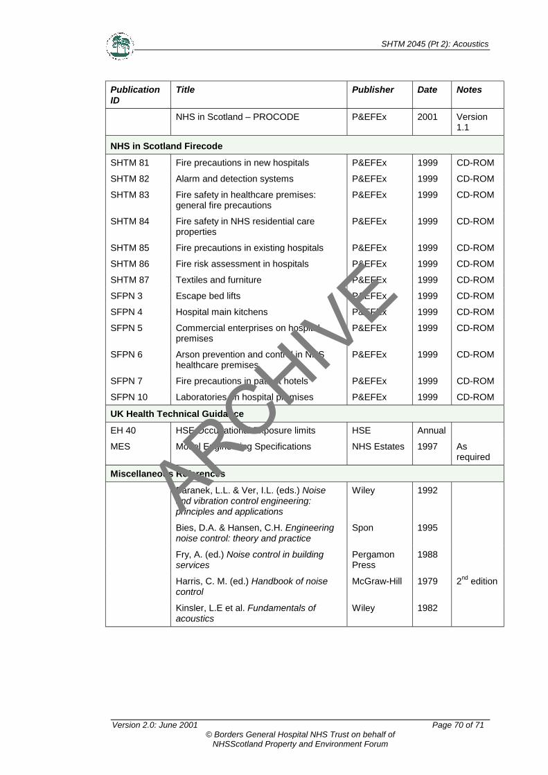
SHTM 2045 (Pt 2): Acoustics
Version 2.0: June 2001 Page 70 of 71© Borders General Hospital NHS Trust on behalf of
NHSScotland Property and Environment Forum
PublicationID
Title Publisher Date Notes
NHS in Scotland – PROCODE P&EFEx 2001 Version1.1
NHS in Scotland Firecode
SHTM 81 Fire precautions in new hospitals P&EFEx 1999 CD-ROM
SHTM 82 Alarm and detection systems P&EFEx 1999 CD-ROM
SHTM 83 Fire safety in healthcare premises:general fire precautions
P&EFEx 1999 CD-ROM
SHTM 84 Fire safety in NHS residential careproperties
P&EFEx 1999 CD-ROM
SHTM 85 Fire precautions in existing hospitals P&EFEx 1999 CD-ROM
SHTM 86 Fire risk assessment in hospitals P&EFEx 1999 CD-ROM
SHTM 87 Textiles and furniture P&EFEx 1999 CD-ROM
SFPN 3 Escape bed lifts P&EFEx 1999 CD-ROM
SFPN 4 Hospital main kitchens P&EFEx 1999 CD-ROM
SFPN 5 Commercial enterprises on hospitalpremises
P&EFEx 1999 CD-ROM
SFPN 6 Arson prevention and control in NHShealthcare premises
P&EFEx 1999 CD-ROM
SFPN 7 Fire precautions in patient hotels P&EFEx 1999 CD-ROM
SFPN 10 Laboratories on hospital premises P&EFEx 1999 CD-ROM
UK Health Technical Guidance
EH 40 HSE Occupational Exposure limits HSE Annual
MES Model Engineering Specifications NHS Estates 1997 Asrequired
Miscellaneous References
Baranek, L.L. & Ver, I.L. (eds.) Noiseand vibration control engineering:principles and applications
Wiley 1992
Bies, D.A. & Hansen, C.H. Engineeringnoise control: theory and practice
Spon 1995
Fry, A. (ed.) Noise control in buildingservices
PergamonPress
1988
Harris, C. M. (ed.) Handbook of noisecontrol
McGraw-Hill 1979 2nd edition
Kinsler, L.E et al. Fundamentals ofacoustics
Wiley 1982
ARCHIVE

SHTM 2045 (Pt 2): Acoustics
Version 2.0: June 2001 Page 71 of 71© Borders General Hospital NHS Trust on behalf of
NHSScotland Property and Environment Forum
PublicationID
Title Publisher Date Notes
Kryter, D. D. The effects of noise on man LondonAcademicPress, NewYork
1985
Noise control in industry SoundResearchLaboratoriesLtd, Spon
1991
Osborne, W. C. & Turner, C. G. (eds.)Practical guide to fan engineering.
Woods ofColchester
1994
Tempest, W. (ed.) Noise handbook AcademicPress
1985
Warring, R. H. (ed.) Handbook on noiseand vibration control
Trade andTechnicalPublications
1983
ARCHIVE