short pin installation during pds · @toyota t-sb-0238-12 december 7, 2012 page 2 of 2 short pin...
TRANSCRIPT
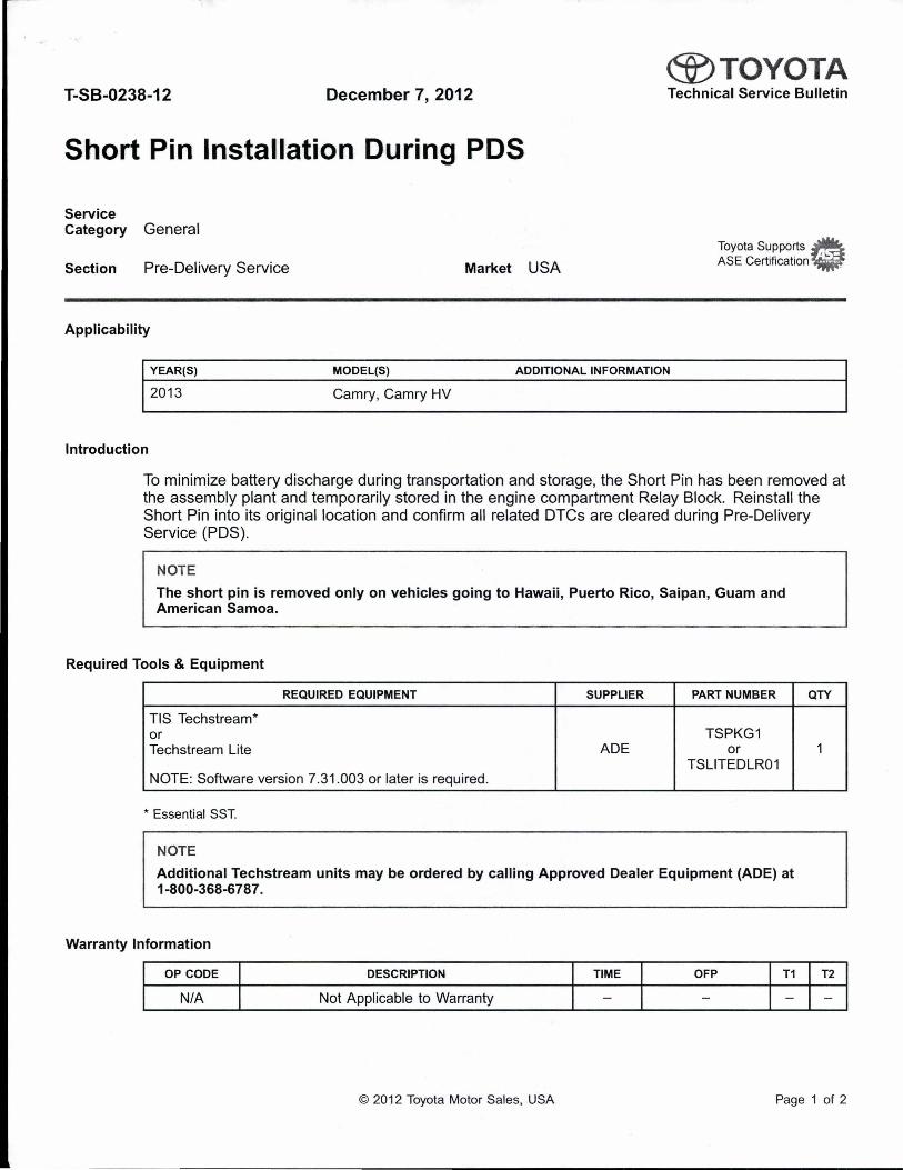
@TOYOTA T-SB-0238-12 December 7, 2012 Technical Service Bulletin
Short Pin Installation During PDS
Service Category General
Section Pre-Delivery Service Market USA
Toyota Supports ~ ASE Certification~
Applicability
YEAR(S) MODEL(S) ADDITIONAL INFORMATION
2013 Camry, Camry HV
Introduction
To minimize battery discharge during transportation and storage, the Short Pin has been removed at the assembly plant and temporarily stored in the engine compartment Relay Block. Reinstall the Short Pin into its original location and confirm all related DTCs are cleared during Pre-Delivery Service (PDS).
NOTE
The short pin is removed only on vehicles going to Hawaii, Puerto Rico, Saipan, Guam and American Samoa.
Required Tools & Equipment
REQUIRED EQUIPMENT SUPPLIER PART NUMBER
TIS Techstream* or TSPKG1 Techstream Lite ADE or
TSLITEDLR01 NOTE: Software version 7.31.003 or later is required.
* Essential SST.
NOTE
Additional Techstream units may be ordered by calling Approved Dealer Equipment (ADE) at 1-800-368-6787.
Warranty Information
OP CODE DESCRIPTION TIME OFP T1
N/A Not Applicable to Warranty - - -
QTY
1
T2
-
© 2012 Toyota Motor Sales, USA Page 1 of 2

@TOYOTA T-SB-0238-12 December 7, 2012 Page 2 of 2
Short Pin Installation During PDS
Installation Procedure
Remove the Short Pin from the blank space of the Relay Block in the engine compartment and install the Short Pin in the Relay Block as shown. Figure 1.
1 Relay Block ~ I 3 I install Short Pin Here
2 Remove this Short Pin
NOTE
• The Short Pin does NOT function as a fuse, so install it only in the position shown.
• If the vehicle is stored in the dealership after PDS, disconnect the negative (-) battery terminal to prevent battery discharge. Refer to Service Bulletin No. PG001-06, "Battery Maintenance for In-Stock Vehicles & Pre-Delivery".
OTC Clearing Procedure
With the Short Pin removed, the occupant classification ECU and Center Airbag Sensor Assembly (airbag ECU) may detect the interruption in battery voltage (B+) and store a OTC. Clear DTCs B1650 and 81794 after installing the Short Pin .
1. Connect TIS Techstream to DLC3.
2. Cycle the ignition switch to the "IG-ON" position.
3. Using TIS Techstream, check any other codes being output.
NOTE
If any DTCs besides 81650 and 81794 remain, repair the applicable system according to the Repair Manual.
4. Erase DTCs (81650 and B1794) and Freeze Frame Data.
© 2012 Toyota Motor Sales, USA
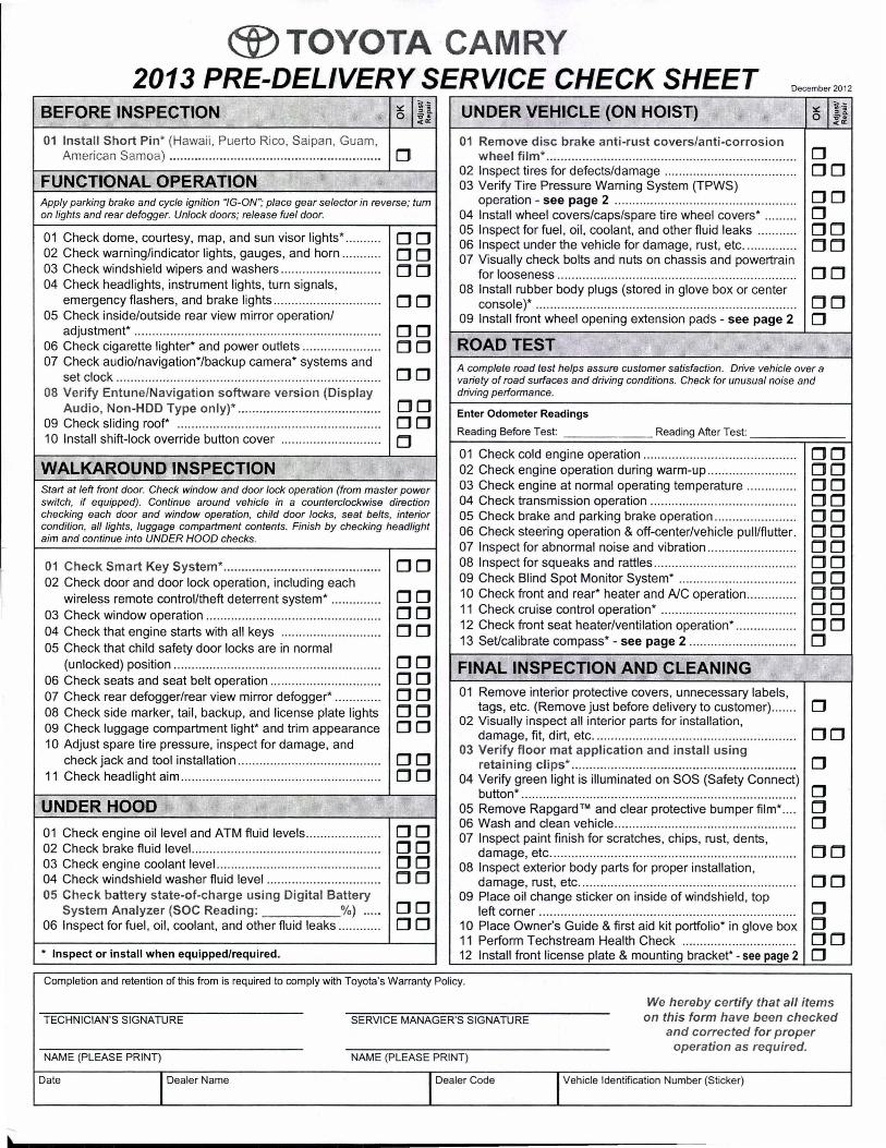
®TOYOTA CAMRY 2013 PRE-DELIVERY SERVICE CHECK SHEET December 2012
BEFORE INSPECTION ~ llii 0 :o'~ c«
01 Install Short Pin* (Hawaii, Puerto Rico, Saipan, Guam, American Samoa) ...... ..................................................... D
FUNCTIONAL OPERATION Apply parking brake and cycle ignition "IG-ON"; place gear selector in reverse; turn on lights and rear defogger. Unlock doors; release fuel door.
01 Check dome, courtesy, map, and sun visor lights* .... ... ... DD 02 Check warning/indicator lights, gauges, and horn ..... .. .... DD 03 Check windshield wipers and washers ... ... .... ... ........ ...... . DD 04 Check headlights, instrument lights, turn signals,
emergency flashers, and brake lights ................. ...... ..... .. DD 05 Check inside/outside rear view mirror operation/
adjustment* ..... ... .... .. .......... ... ...... .. ..... ........... .... ... ......... .. DD 06 Check cigarette lighter* and power outlets ...... ... ..... ..... ... DD 07 Check audio/navigation*/backup camera* systems and
DD set clock ... .... ... ..... .. .. ... ... .. .......... .... .. ... ......... ... .. .. ........... . 08 Verify Entune/Navigation software version (Display
DD Audio, Non-HOD Type only)* .................... .................... 09 Check sliding roof* ···· ·· ···· ·· ·· ·· ··· ··· ··· ·· ···· ·· ··· ···· ···· ·· ··········· DD 10 Install sh ift-lock override button cover .... .... ... ................. D WALKAROUND INSPECTION Start at left front door. Check window and door lock operation (from master power switch, if equipped). Continue around vehicle in a counterclockwise direction checking each door and window operation, child door locks, seat belts, interior condition, all lights, luggage compartment contents. Finish by checking headlight aim and continue into UNDER HOOD checks.
01 Check Smart Key System* ........ .... ....... .. ... .. .. ................ DD 02 Check door and door lock operation, including each
wireless remote control/theft deterrent system* .... .. ... ..... DD 03 Check window operation .. .... ... ... ... ..... ... ...... .... ..... ... ........ DD 04 Check that engine starts with all keys .. .. .. ...... ........ ... .... . DD 05 Check that child safety door locks are in normal
(unlocked) position ..... ........ ... ..... ..... .. .... .... .. ... ... ........... ... DD 06 Check seats and seat belt operation ..... .... ............ ... ..... .. DD 07 Check rear defogger/rear view mirror defogger* .... ... ... ... DD 08 Check side marker, tail, backup, and license plate lights DD 09 Check luggage compartment light* and trim appearance DD 10 Adjust spare tire pressure, inspect for damage, and
check jack and tool installation ...... ............... .... ........... ... . DD 11 Check headlight aim .. .. .... .. ... .. ... ...... ... ... ... .. .. .. ..... ....... .... . DD
UNDER HOOD
01 Check engine oil level and ATM fluid levels ........... ..... .... . DD 02 Check brake fluid level. ..................................... ..... ......... . DD 03 Check engine coolant level. .. ... ....... .............. ..... ...... ..... ... DD 04 Check windshield washer fluid level ...... ........... ... ... ........ . DD 05 Check battery state-of-charge using Digital Battery
DD System Analyzer (SOC Reading : %) ..... 06 Inspect for fuel , oil , coolant, and other fluid leaks .... .. .. ... . DD * Inspect or install when equipped/required.
UNDER VEHICLE (ON HOIST)
01 Remove disc brake anti-rust covers/anti-corrosion wheel film* ..................................................................... .
02 Inspect tires for defects/damage ... .. ... ... ........ .... ....... ... ... . 03 Verify Tire Pressure Warning System (TPWS)
operation - see page 2 ..... ......... ... ... .... ..... .... ... ... .. .... .. ... . 04 Install wheel covers/caps/spare tire wheel covers* ... .... . . 05 Inspect for fuel, oil, coolant, and other fluid leaks ..... .. .. . . 06 Inspect under the vehicle for damage, rust, etc ... ... ........ . 07 Visually check bolts and nuts on chassis and powertrain
for looseness .... ... .. ...... ..................... .... ..... .... ............... .. . 08 Install rubber body plugs (stored in glove box or center
console)* .................... .. ......... ... ...... ...... .... ..... ... ....... .. ..... . 09 Install front wheel opening extension pads - see page 2
ROAD TEST
D DD DD D DD DD DD DD D
A complete road test helps assure customer satisfaction. Drive vehicle over a variety of road surfaces and driving conditions. Check for unusual noise and driving performance.
Enter Odometer Readings
Reading Before Test: Reading After Test:
01 Check cold engine operation ..... ..... .......... .. ..... .... ... ... .... . . 02 Check engine operation during warm-up ........... ... ...... .... . 03 Check engine at normal operating temperature ....... .... .. . 04 Check transmission operation ..... ... .. ... ............. .... .. .. .. .. .. . 05 Check brake and parking brake operation .. ...... ............ .. . 06 Check steering operation & off-center/vehicle pull/flutter . 07 Inspect for abnormal noise and vibration ... .... ...... .... ....... . 08 Inspect for squeaks and rattles ...... ......... .... ... .... ... ..... ..... . 09 Check Blind Spot Monitor System* ...... ... ....................... . 10 Check front and rear* heater and A/C operation .... ....... .. . 11 Check cruise control operation* .. .... ......... ... ... ..... .. .... .... . . 12 Check front seat heater/ventilation operation* .. .. .. .. ... .... . . 13 Set/calibrate compass* - see page 2 ......... .. .. .... ... ... ...... .
FINAL INSPECTION AND CLEANING 01 Remove interior protective covers , unnecessary labels,
tags, etc. (Remove just before delivery to customer) .. ... . . 02 Visually inspect all interior parts for installation,
damage, fit, dirt, etc . ...... .. ... .. ... .................. ... .. .... ...... .... .. . 03 Verify floor mat application and install using
retaining clips* .................... ..... .............. ... ... ................. .
DD DD DD DD DD DD DD DD DD DD DD DD D
D
DD D
04 Verify green light is illuminated on SOS (Safety Connect) button*.... ....... ... ... ..... ..... ... .. ....... ..... ....... .. ... .. .. ........ ....... .. D
05 Remove Rapgard™ and clear protective bumper film* .... D 06 Wash and clean vehicle ...... ....... ..... .............. ... .. .. .... .... .... D 07 Inspect paint finish for scratches, chips, rust, dents,
damage, etc . .. ..... ......... ...... ... ...... .... ..... .......... ........ .... ..... . 08 Inspect exterior body parts for proper installation,
damage, rust, etc . ..... .................. .... .... ... ..... ......... .. .. .... .. . . 09 Place oil change sticker on inside of windshield, top
left corner ....... ..... .. ...... ... ..... ....... .......... ...... .. .... ... .. ......... . 10 Place Owner's Guide & first aid kit portfolio* in glove box 11 Perform T echstream Health Check ........... ..... ..... ... .... ... . 12 Install front license plate & mounting bracket* - see page 2
DD DD D D DD D
Completion and retention of this from is required to comply with Toyota's Warranty Policy.
TECHNICIAN'S SIGNATURE
NAME (PLEASE PRINT)
Date I Dealer Name
SERVICE MANAGER'S SIGNATURE
NAME (PLEASE PRINT)
I Dealer Code
We hereby certify that all items on this form have been checked
and corrected for proper operation as required.
I Vehicle Identification Number (Sticker)
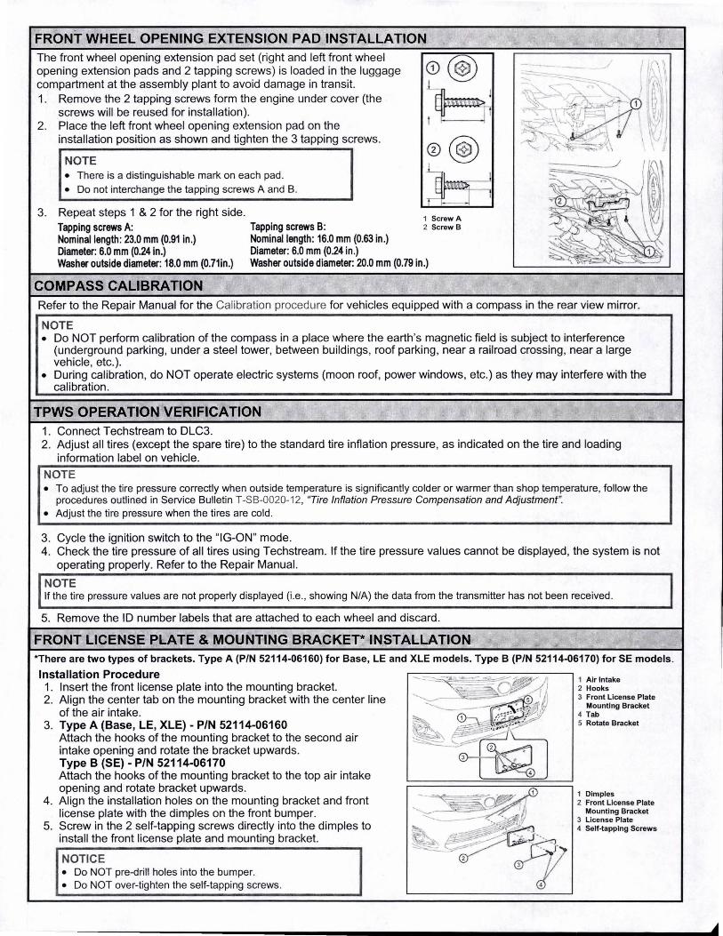
FRONT WHEEL OPENING EXTENSION PAD INSTALLATION The front wheel opening extension pad set (right and left front wheel opening extension pads and 2 tapping screws) is loaded in the luggage compartment at the assembly plant to avoid damage in transit. 1. Remove the 2 tapping screws form the engine under cover (the
screws will be reused for installation). 2. Place the left front wheel opening extension pad on the
installation position as shown and tighten the 3 tapping screws.
NOTE • There is a distinguishable mark on each pad . • Do not interchange the tapping screws A and B.
3. Repeat steps 1 & 2 for the right side. Tapping screws A: Tapping screws B: Nominal length: 23.0 mm (0.91 in.) Nominal length: 16.0 mm (0.63 in.) Diameter: 6.0 mm (0.24 in.) Diameter: 6.0 mm (0.24 in.)
CD @ t~P 0@
1 Screw A 2 Screw B
Washer outside diameter: 18.0 mm (0.71in.) Washer outside diameter: 20.0 mm (0.79 in.)
COMPASS CALIBRATION Refer to the Repair Manual for the Calibration procedure for vehicles equipped with a compass in the rear view mirror.
NOTE • Do NOT perform calibration of the compass in a place where the earth 's magnetic field is subject to interference
(underground parking , under a steel tower, between buildings, roof parking, near a railroad crossing, near a large vehicle, etc.).
• During calibration, do NOT operate electric systems (moon roof, power windows, etc.) as they may interfere with the calibration .
TPWS OPERATION VERIFICATION 1. Connect Techstream to DLC3. 2. Adjust all tires (except the spare tire) to the standard tire inflation pressure, as indicated on the tire and loading
information label on vehicle. ·
NOTE • To adjust the tire pressure correctly when outside temperature is significantly colder or warmer than shop temperature, follow the
procedures outlined in Service Bulletin T-SB-0020-12, ''Tire Inflation Pressure Compensation and Adjustment". • Adjust the tire pressure when the tires are cold.
3. Cycle the ignition switch to the "IG-ON" mode. 4. Check the tire pressure of all tires using Techstream. If the tire pressure values cannot be displayed, the system is not
operating properly. Refer to the Repair Manual.
NOTE If the tire pressure values are not properly displayed (i.e. , showing N/A) the data from the transmitter has not been received .
5. Remove the ID number labels that are attached to each wheel and discard.
FRONT LICENSE PLATE & MOUNTING BRACKET* INSTALLATION *There are two types of brackets. Type A (P/N 52114-06160) for Base, LE and XLE models. Type B (P/N 52114-06170) for SE models .
Installation Procedure 1. Insert the front license plate into the mounting bracket. 2. Align the center tab on the mounting bracket with the center line
of the air intake. 3. Type A (Base, LE, XLE) - P/N 52114-06160
Attach the hooks of the mounting bracket to the second air intake opening and rotate the bracket upwards. Type B (SE) - P/N 52114-06170 Attach the hooks of the mounting bracket to the top air intake opening and rotate bracket upwards.
4. Align the installation holes on the mounting bracket and front license plate with the dimples on the front bumper.
5. Screw in the 2 self-tapping screws directly into the dimples to install the front license plate and mounting bracket.
NOTICE • Do NOT pre-drill holes into the bumper. • Do NOT over-tighten the self-tapping screws.
1 Air Intake 2 Hooks 3 Front License Plate
Mounting Bracket 4 Tab 5 Rotate Bracket
1 Dimples 2 Front License Plate
Mounting Bracket 3 License Plate 4 Self-tapping Screws