short-cavity picosecond dye laser design
TRANSCRIPT

Short-cavity picosecond dye laser design
A. J. Cox and Gary W. Scott
The design of a short-cavity dye laser is described. The laser produces a 2-psec pulse which is tunable in therange between 400 nm and 470 nm when pumped with an 8-psec 355-nm third-harmonic pulse from a mode-locked Nd+3 :glass laser. The laser features a variable calibrated cavity length (10-500 m), a dye cellthrough which dye can be continuously flowed, and a compact rugged design. The laser has been incorpo-rated into several picosecond spectroscopy experiments and has proved to be a convenient and useful tun-able blue source.
1. Introduction
A short-cavity dye laser has been constructed whichproduces a narrow linewidth, tunable, blue picosecondpulse when pumped with a single picosecond uv pulsefrom a mode-locked laser.1'2 The dye laser features acontinuously variable calibrated cavity length, a dye cellthrough which dye can be flowed for easy dye exchangeor cleaning, and a compact rugged design. This paperpresents the details of the design and summarizes thelaser's operating characteristics.
The short output pulse duration is due to the laser'sextremely short cavity photon lifetime.3 This lifetimeresults from the short optical cavity lengths, typicallyin the 50-300-m range. By pumping with a single uvpicosecond pulse (third harmonic of a mode-lockedNd+3 :glass laser) and using blue dyes, the laser producesa picosecond pulse in the 400-470-nm range. It is thusa convenient source of tunable blue picosecond pulsesfor use in spectroscopy experiments.
11. Design
The optical cavity is formed by two closely spacedmirrors which are each coated on 2.54-cm diam, 0.95-cmthick quartz substrates, flat to X/20. A schematic di-agram of the laser is shown in Fig. 1. The laser is axiallypumped by a focused uv pulse at 355 nm. The firstsurface of mirror 1 (Ml) has an antireflection V-coat at355 nm (AR 1), and the second surface has a special di-chroic coating (R 1) which transmits 85% of the uv pump
A. J. Cox is with University of Redlands, Physics Department,Redlands, California 92373, and G. W. Scott is with University ofCalifornia at Riverside, Chemistry Department, Riverside, California92521.
Received 16 June 1978.0003-6935/79/040532-04$00.50/0.© 1979 Optical Society of America.
pulse and reflects more than 95% from 390 nm to 460nm. The first surface of mirror 2 (M2) is coated (R2)to reflect 30-50% in the same wavelength region, whileits second surface is broadband AR coated (AR 2).4
The mirrors form a flat-flat optical cavity with alength that can be continuously varied in the 0-500-,gmrange. This cavity is entirely filled with dye solutionwhich can be flowed uniformly between the cavitymirrors. The laser is designed so that the only availablepath for dye flow is across the thin optical cavity. Ef-ficient dye exchange and cleaning can be accomplishedwithout disassembling or moving the laser.
The dye cell is formed by cementing the two mirrorsinto aluminum support rings (ALl and AL 2), which are7.62 cm in diameter and 1.59 cm thick. The two mirrorsurfaces protrude approximately 0.05 cm beyond eachaluminum ring surface. The ALl ring has a 0.10-cmdeep o-ring groove machined around the outside of themirror. The mirror M2 has two flat bevels, each 1.43cm long, ground off the edges at 450 to the mirror sur-face on opposite sides of the mirror. When M2 ismounted in AL2, small spaces are thus left between thealuminum and the beveled mirror edge on the oppositesides of the mirror. Two holes, 0.24 cm in diameter, aredrilled at a 450 angle into AL2 starting at each of thesespaces. These holes open into 0.86-cm diam port holes,perpendicular to the small holes. When the aluminumrings are brought together with the o-ring in place, theo-ring serves as the side wall of the very short opticalcavity-dye cell. Dye solutions are introduced into oneof the 0.86-cm diam ports by way of Teflon tubing anda Swagelock brass fitting. The dye flows into the port,through the smaller angled hole, to the space betweenthe o-ring and the beveled edge of M2, then across thedye cell to the opposite beveled edge-o-ring space, andout through the opposite port.
Two 1.27-cm long 0.32-cm diam alignment pins arepress-fitted into holes in the face of an aluminum ringAL1 on opposite sides of the mirror. These pins fit
532 APPLIED OPTICS / Vol. 18, No. 4 / 15 February 1979

UV > ;//////t/////// blue laserpump output
ARt Ml', AR 2
0-ring
dyeAlignment inPin
AL l AL 2
Fig. 1. Schematic cross section of the short-cavity dye laser. Mirrors(Ml and M2) are cemented with RTV (G.E. Silicone Seal) into con-centric aluminum rings (ALl and AL2, respectively). The opticalcavity is sealed with a viton o-ring, which is held in an o-ring groove
in AL1 by pressure from AL2.
loosely into mating holes in the face of the other alu-minum ring AL2. The pins maintain approximatealignment of the two mirror surfaces, perpendicular tothe common optical axis, as the mirror-ring combina-tion is brought together during assembly. When theo-ring is only slightly compressed during assembly, themirrors are spaced by approximately 500 gim. Thevariable short cavity lengths are achieved by pushingthe mirror-ring assembly, M2-AL2, against the fixedassembly, Mi-AL1, and thus compressing the o-ring,as described below.
Figure 2 shows the complete dye laser assembly, anda photograph of the actual device is shown in Fig. 3. Asshown in these figures, ALl is bolted to a larger alumi-num ring 10.16 cm in diameter and 1.27 cm thick. Thelarger ring is rigidly attached to a mounting plate andserves as the fixed end plate of the laser main frame.Three 0.95-cm diam 8.45-cm long brass connecting rodsare bolted to this end plate and also to a second largering, 10.16 cm in diameter and 2.29 cm thick, the op-posite end plate of the laser main frame. Three mi-crometer heads are mounted symmetrically in the sec-ond end plate. The micrometers are positioned to pushthe mirror assembly, M2-AL2, against Mi-AL 1. Themicrometer heads are Mitutoyu model 51-222 calibratedto gm. The flat carbon-steel tips of the micrometerheads push against 0.64-cm steel ball bearings which areembedded to one half their diameter in the mirrormount ring AL2. By adjusting the micrometers theamount of o-ring compression and thus the opticalcavity-dye cell length may be varied. Therefore, theo-ring serves both for sealing the sides of the dye cell andalso as a preloaded spring against which the microme-ters press. Adjustments of individual micrometers arealso used to bring the mirrors into parallel alignment.
Support ring AL2 is mounted so that the dye portsare horizontal. Dye is introduced through the bottom
Brass Connecting Rods
Fig. 2. A schematic drawing ofthe short cavity dye laser (not toscale) showing the mirror-ring as-sembly (Ml-ALl and M2-AL2),the main frame ends connected bythe brass connecting rods, and themicrometers. In the side viewshown, laser pulses would travel
from left to right.
A
Side View (Section A-A) Rear View
15 February 1979 / Vol. 18, No. 4 / APPLIED OPTICS 533
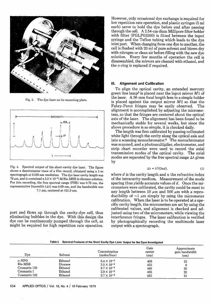
Fig. 3. The dye laser on its mounting plate.
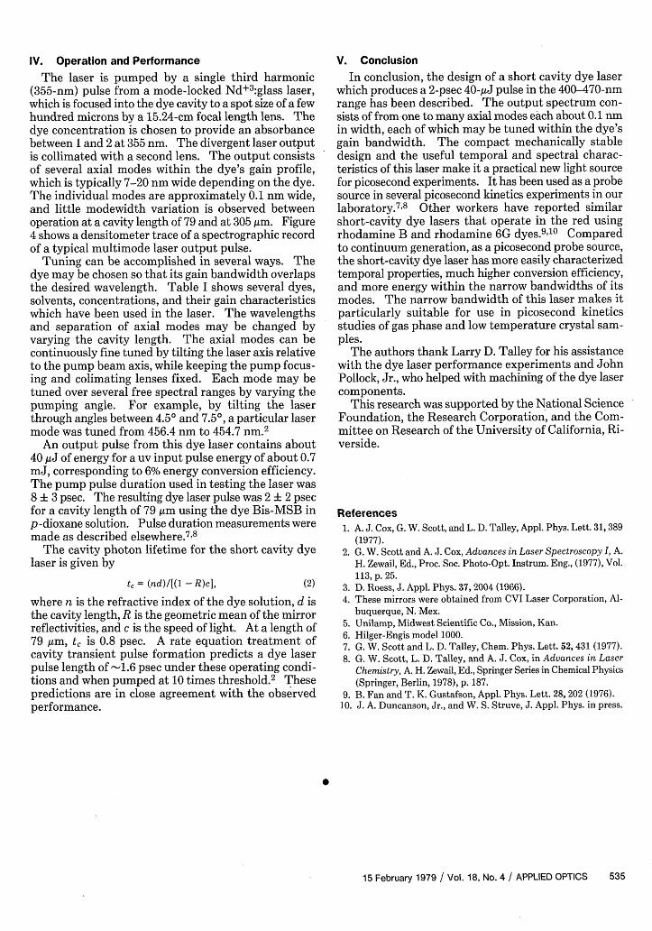
Fig. 4. Spectral output of the short-cavity dye laser. The figureshows a densitometer trace of a film record, obtained using a 1-mspectrograph at 0.020-nm resolution. The dye laser cavity length was79 ,um, and it contained a 3.2 X 10⁻³ -M Bis-MSB in dioxane solution.For this recording, the free spectral range (FSR) was 0.79 nm, therepresentative linewidth (AX) was 0.09 nm, and the bandwidth was
7.1 nm, centered at 421.9 nm.
port and flows up through the cavity-dye cell, thuseliminating bubbles in the dye. With this design thedye can be continuously pumped through the cell, asmight be required for high repetition rate operation.
However, only occasional dye exchange is required forlow repetition rate operation, and plastic syringes (5 mleach) serve to hold the dye before and after passingthrough the cell. A 2.54-cm diam Millipore filter holderwith filter (FGLP02500) is fitted between the inputsyringe and the Teflon tubing which leads to the dyeinlet port. When changing from one dye to another, thecell is flushed with 20 ml of pure solvent and blown drywith nitrogen or clean air before filling with the new dyesolution. Every few months of operation the cell isdisassembled, the mirrors are cleaned with ethanol, andthe o-ring is replaced if required.
Ill. Alignment and CalibrationTo align the optical cavity, an extended mercury
green line lamp5 is placed near the input mirror Ml ofthe laser. A 36-mm focal length lens in a simple holderis placed against the output mirror M2 so that theFabry-Perot fringes may be easily observed. Thealignment is accomplished by adjusting the microme-ters, so that the fringes are centered about the opticalaxis of the laser. The alignment has been found to bemechanically stable for several weeks, but since theabove procedure is so simple, it is checked daily.
The length was first calibrated by passing collimatedwhite light through the cavity along the optical axis andinto a scanning monochromator. 6 The monochromatorwas scanned, and a photomultiplier, electrometer, andstrip chart recorder were used to record the axialtransmission modes of the optical cavity. The axialmodes are separated by the free spectral range AX givenby
AX A2 /(2nd), (1)
where d is the cavity length and n the refractive indexof the intracavity medium. Measurement of the modespacing thus yields accurate values of d. Once the mi-crometers were calibrated, the cavity could be reset toany length between 10 ,m and 500 Am with a repro-ducibility of -1 m simply by using the micrometercalibration. When the laser is to be operated at a spe-cific cavity length, the micrometers are set by using thecalibrated values, and alignment is checked and ad-justed using two of the micrometers, while viewing theinterference fringes. The laser calibration is verifiedby photographically recording the multimode laseroutput with a spectrograph.
Table 1. Spectral Features of the Short Cavity Dye Laser Output for the Dyes Investigated
Gain ApproximateConcentration center gain bandwidth
Dye Solvent (moles/liter) (nm) (nm)
a-NPO Ethanol 6.4 X 10⁻³ 408 23Bis-MSB Dioxane 3.5 X 10⁻³ 423 9Coumarin 120 Ethanol 8.7 x 10⁻³ 440 20Coumarin I Ethanol 2.9 X 10⁻² 455 20Coumarin 102 Ethanol 2.7 X 10⁻² 462 15
534 APPLIED OPTICS / Vol. 18, No. 4 / 15 February 1979
BaNDWIDTH N!
I IX
IV. Operation and Performance
The laser is pumped by a single third harmonic(355-nm) pulse from a mode-locked Nd+ 3 :glass laser,which is focused into the dye cavity to a spot size of a fewhundred microns by a 15.24-cm focal length lens. Thedye concentration is chosen to provide an absorbancebetween 1 and 2 at 355 nm. The divergent laser outputis collimated with a second lens. The output consistsof several axial modes within the dye's gain profile,which is typically 7-20 nm wide depending on the dye.The individual modes are approximately 0.1 nm wide,and little modewidth variation is observed betweenoperation at a cavity length of 79 and at 305 pm. Figure4 shows a densitometer trace of a spectrographic recordof a typical multimode laser output pulse.
Tuning can be accomplished in several ways. Thedye may be chosen so that its gain bandwidth overlapsthe desired wavelength. Table I shows several dyes,solvents, concentrations, and their gain characteristicswhich have been used in the laser. The wavelengthsand separation of axial modes may be changed byvarying the cavity length. The axial modes can becontinuously fine tuned by tilting the laser axis relativeto the pump beam axis, while keeping the pump focus-ing and colimating lenses fixed. Each mode may betuned over several free spectral ranges by varying thepumping angle. For example, by tilting the laserthrough angles between 4.5° and 7.5°, a particular lasermode was tuned from 456.4 nm to 454.7 nm.2
An output pulse from this dye laser contains about40 gJ of energy for a uv input pulse energy of about 0.7mJ, corresponding to 6% energy conversion efficiency.The pump pulse duration used in testing the laser was8 3 psec. The resulting dye laser pulse was 2 ± 2 psecfor a cavity length of 79 pm using the dye Bis-MSB inp-dioxane solution. Pulse duration measurements weremade as described elsewhere. 7 8
The cavity photon lifetime for the short cavity dyelaser is given by
t = (nd)/[(l - R)c], (2)
where n is the refractive index of the dye solution, d isthe cavity length, R is the geometric mean of the mirrorreflectivities, and c is the speed of light. At a length of79 m, t is 0.8 psec. A rate equation treatment ofcavity transient pulse formation predicts a dye laserpulse length of -1.6 psec under these operating condi-tions and when pumped at 10 times threshold.2 Thesepredictions are in close agreement with the observedperformance.
V. Conclusion
In conclusion, the design of a short cavity dye laserwhich produces a 2-psec 40-gJ pulse in the 400-470-nmrange has been described. The output spectrum con-sists of from one to many axial modes each about 0.1 nmin width, each of which may be tuned within the dye'sgain bandwidth. The compact mechanically stabledesign and the useful temporal and spectral charac-teristics of this laser make it a practical new light sourcefor picosecond experiments. It has been used as a probesource in several picosecond kinetics experiments in ourlaboratory.78 Other workers have reported similarshort-cavity dye lasers that operate in the red usingrhodamine B and rhodamine 6G dyes.910 Comparedto continuum generation, as a picosecond probe source,the short-cavity dye laser has more easily characterizedtemporal properties, much higher conversion efficiency,and more energy within the narrow bandwidths of itsmodes. The narrow bandwidth of this laser makes itparticularly suitable for use in picosecond kineticsstudies of gas phase and low temperature crystal sam-ples.
The authors thank Larry D. Talley for his assistancewith the dye laser performance experiments and JohnPollock, Jr., who helped with machining of the dye lasercomponents.
This research was supported by the National ScienceFoundation, the Research Corporation, and the Com-mittee on Research of the University of California, Ri-verside.
References1. A. J. Cox, G. W. Scott, and L. D. Talley, Appl. Phys. Lett. 31, 389
(1977).2. G. W. Scott and A. J. Cox, Advances in Laser Spectroscopy I, A.
H. Zewail, Ed., Proc. Soc. Photo-Opt. Instrum. Eng., (1977), Vol.113, p. 25.
3. D. Roess, J. Appl. Phys. 37, 2004 (1966).4. These mirrors were obtained from CVI Laser Corporation, Al-
buquerque, N. Mex.5. Unilamp, Midwest Scientific Co., Mission, Kan.6. Hilger-Engis model 1000.7. G. W. Scott and L. D. Talley, Chem. Phys. Lett. 52, 431 (1977).8. G. W. Scott, L. D. Talley, and A. J. Cox, in Advances in Laser
Chemistry, A. H. Zewail, Ed., Springer Series in Chemical Physics(Springer, Berlin, 1978), p. 187.
9. B. Fan and T. K. Gustafson, Appl. Phys. Lett. 28, 202 (1976).10. J. A. Duncanson, Jr., and W. S. Struve, J. Appl. Phys. in press.
0
15 February 1979 / Vol. 18, No. 4 / APPLIED OPTICS 535