shop work basics bleeding brakes - gavilan...
TRANSCRIPT

Shop Work Basics
Bleeding Brakes Any air bubbles in the system will cause a spongy pedal. Here's how to help avoid as well as cure the problem.
BY MIKE BERRY, IA
One of the most difficult tasks regarding aircraft brakes is that of "bleeding" or eliminating air from the braking system, which ensures proper brake
operation. I will discuss hydraulic brake operation and specifically the procedures for eliminating air from the brake system and how to prevent air or dirt from entering during maintenance.
Before getting into the process of bleeding we must understand how the system works and the basic design of an aircraft hydraulic brake system. We will be discussing brake systems on the typical light aircraft that have no power assist and use aircraft standard petroleum hydraulic fluid.
This is an important distinction from that of automotive systems that are generally power assisted and use a fluid that is not petroleum based. Never use automotive brake fluid in any aircraft hydraulic system including the brakes as the fluids are not interchangeable and will destroy elastic seals in hydraulic components.
This is a typical layout of the aircraft braking system with a master cylinder for each pedal. Access to the master cylinders can vary from not too bad to awful for getting to the fluid filler when no other fluid reservoir is provided.
Also note that the standard 5606G of many years has a newer version, 5606H, which is basically an oxidation-inhibited version of the previous type. They can be mixed.
SYSTEM DESIGN Aircraft brake systems are made up of the most basic components; a master cylinder or cylinders, fluid transfer lines, a slave or wheel cylinder, and a fluid reservoir (which can be integral with the master cylinder). Some if not most aircraft have a parking brake valve; some are equipped with dual master brake cylinders; some have only one master cylinder but two wheel cylinders; others have four master brake cylinders with a shuttle valve between the left and right master cylinders.
Some systems are even more complicated in that they incorporate a hand brake (single master cylinder) and dual toe brakes. It is important to know and understand the exact system that you are working with as each component as well as the position in the aircraft where the component is located.
For all practical purposes liquids are incompressible, making hydraulic systems so darn helpful. Pascal's law states that a confined hydraulic pressure exerts equal pressure at every point and every
direction in the fluid. Another important fact
BRAKE PEDALS is that hydraulic force can be multiplied to almost any degree by the proper application
FLIUD FILLER
.. APRIL 2011
of hydraulic pressure. When air and a liquid (hydraulic fluid) are mixed in a closed system the air can (and will) compress interfering with the proper hydraulic operation of the brake system. This is the cause of soft or spongy brakes; air mixed with hydraulic fluid in the system.
The causes of air entering the system can be obvious
such as when a brake line is disconnected exposing the system to air. Other causes of air entering the system are hydraulic lines in poor condition allowing air to enter (leak) into the system at certain times.
While it may seem intuitive that fluid will leak out if air can enter, this is not always the case. It depends on where in the system the leak is. Elastic a-ring seals that are "aged" or in poor condition can allow air to enter the system, especially during periods of cold weather when seals are not as flexible. Brake systems can also have internal leaks only, such as one or both toe brakes slowly compressing to the floor while you hold position with them.
Another problem that interferes with braking and all hydraulic systems is moisture. Moisture can freeze or cause ice crystals to block or partially clog the system and liquid water can cause corrosion and rust of internal components.
Aircraft brake systems use fluid that is trapped in the system and this fluid does not return to the reservoir to mix with freshly added fluid. In other words there is no circulation per say. This is why it is important to always use clean, fresh hydraulic fluid, especially when bleeding; never re-use hydraulic fluid and always use a clean container for the transfer of fluid.
BRAKE BLEEDING BASICS The theory of bleeding brakes is that generally fluid under pressure is used to expel air from the brake system. Pressure can be supplied from the normal master cylinder or by any other method to pressurize the brake lines.
A bleeding port or screw is located on the brake wheel cylinder (caliper) to
UPFRONT TIPS • Always use the proper Mil 5606H brake
fluid, not automotive types
• Be sure to thoroughly clean any fitting/ area to avoid fluid contamination
• A spongy pedal generally means air is in the system at some point
• A pedal that slowly depresses when held often means internal O-ring leaks
LIGHT PLANE MAINTENANCE

allow for air to be expelled during the bleeding operation. In theory one person can depress the master cylinder to pump up pressure while another person opens the bleeder screw briefly to allow air to escape. This usually turns out to be an "iffy" proposition because air bubbles have a tendency to migrate into very hard to expel spots in the system.
Probably the most common method to bleed brakes is using a clear, flexible plastic line connected to the bleeder screw outlet at one end, and the other end submerged into a container of hydraulic fluid. This will allow the person at the bleeder screw to watch for air bubbles escaping during the brief time that the bleeder screw is opened and pressure is applied for the bleeding process. (The plastic tube must always be under the fluid when the line is open).
While this works, most bleeding operations done in this fashion have limited success depending on where in the system the air is trapped. During the bleeding operation, air bubbles generally travel upwards so that a bleeder screw placed in the lower part of the system cannot be expected to allow air to escape from a location above the bleeder screw. It is difficult to force air downward since it wants to rise.
Another factor is that the master cylinder used in the typical light aircraft transfers a very minor amount of fluid volume with each full application of pedal or stroke. Installed components such as hand brake cylinders, and parking brake valves further complicate the process of expelling air by providing nooks and crannies for air to get trapped, no matter how much pressure/volume you use. If you really are seeking a firm brake pedal with no air then you must be committed to eliminate every speck if air from each individual component of the system.
This starts with learning how to avoid contaminating the system with air in the first place. It is far easier to keep the air out than to try to bleed it out once it is in the system.
Any time a component of the brake system is removed precautions must be observed to prevent entrance of air or dirt. Replacement of the O-Ring seals on a master cylinder, for example, can allow large amounts of air to enter the system during the process.
When removing the top of the master
www.lightplane-maintenance.com
cylinder to replace O-Rings, immediately install a rubber plug similar to a thermos bottle type plug/stopper that temporarily seals the master cylinder to keep air from entering and fluid from escaping.
When reinstalling the top of the master cylinder make certain that the O-ring seals on the sealing screw are lubed and that you have everything you need to complete the installation quickly. If there is any air trapped in the master cylinder and you depress the brake pedal then this air is forced into the system, so never force air into the system with an un-bled component.
Another installation tip is that of disconnecting the wheel cylinder or when disconnecting any fluid supply line, install a cap and/or plug (and snug it down) to prevent air and debris from entering (it won't keep out all the air, however). As always, when disassembling the wheel cylinder, or any other component, inspect carefully for cracks, corrosion, and damage. Cracks in the wheel cylinder hOUSing are now becoming common with the increasing age of equipment in service and can be a cause of system leaks both in terms of air entering or fluid leaking.
After completely removing the wheel cylinder (caliper) from the aircraft you can use a slight (5 psi max) amount of air pressure to expel the piston from the cylinder through the bleeder port boss (after removing the bleeder screw and fitting). Take proper safety precautions with the use of protective eye wear and do not allow the piston to be damaged in this process (use of several shop rags around the piston is good).
damage and replace the O-Ring with the proper size and type using O-Ring lubricant.
Cap the fluid line outlet on the brake cylinder and install/close the bleeder port, and then fill the cavity completely with hydraulic fluid before installing the piston. It may be necessary to crack the cap and bleeder screw when pushing the piston into position to bleed all air from these cavities.
The purpose of this operation is to eliminate all air and fill all cavities completely with clean, fresh hydraulic fluid. When installing the piston, push it just far enough so that the O-Ring is fully engaged in the cylinder but no more.
When installing the wheel cylinder on the aircraft remove the fluid cap and plug it just before connecting the fluid line. Before tightening the fittings push the piston slowly into the cylinder to expel fluid and any air in the cavity. Finally close the fitting as the piston is just finished being slowly pushed in.
Every component that is removed and reinstalled must be done in this manner.
Of the two ways to bleed brakes, the pressure pot on left is by far the easiest way. The top down gravity method is at right. The pressure pot is only around $95. An oil squirt can may be substituted for the pot but is tricky to use.
Do not use pliers or any other metal tool to remove the piston as it will be damaged and will have to be replaced. Clean the cylinder and piston completely, carefully checking for cracks or ._-------_._-----_._--_.
APRIL2011 ..

Arrows point to the master cylinders. Typically one is installed for each pedal. You commonly find plastic plug covers provide access to adding fluid, if required. Be very careful not to contaminate the area with existing dirt when opening them up.
Fill the component in the most extended position with hydraulic fluid, eliminate all air and then install with pressure applied to the component whenever possible to expel trapped air. Always use caps and plugs to seal the system any time a fitting is removed or opened.
THE BLEEDING PROCESS The practical aspects of the bleeding operation are that the fluid must be applied from the bottom of the system, and the air bled out from the bottom up. The ideal equipment to use is a pressure pot with approximately a gallon of hydraulic fluid under pressure applied to the bleeder port on the wheel cylinder.
This pressure pot and adapter for Cleveland brakes is available from
The Cleveland bleeding tool makes using a pressure pot even easier to use. Cost is under $10 from ATS Tool.
Aircraft Tool Supply on the web, www. aircraft-tool.com or 800-248-0638. The amount of pressure is not important but the volume must be sufficient to expel all the air.
A high quality metal oil squirt can could also be used to act like a low buck version of the pressure pot. You attach a flexible clear line to the tip of the oil feed tip and the other end of the tube is connected to the bleeder port.
However, this could allow more air to be introduced into the system if not done "just right." The operator of the squirt can must be vigilant in preventing the can from running empty or allOwing the hose to become disconnected from the bleeder port and must also watch the clear plastic line for air bubbles.
While one person can bleed the system with the proper equipment it is best to not attempt it unless you are experienced with this procedure and check the pressure pot frequently for the presence of fluid. For all practical purposes this is a two-person job.
Start at the bottom and work your way up. One person must crack and tighten all connections while the system is under slight pressure to allow air to be expelled.
When you get to the parking brake valve the valve should be operated before cracking the fittings and ideally during the bleeding operation when the upstream fitting is being cracked and tightened
The location of the parking brake valve certainly is not in a position to allow for easy bleeding but it must be done as these valves allow air to be trapped. Another component is that of the parking brake cylinder or mas-
ter cylinder on the Piper aircraft. Again, these are difficult to gain access to but are a very big problem with trapped air.
If there is any air trapped in these components actuating (pumping) the cylinder will force air into various parts of the system. It may be necessary to remove the cylinder completely and bleed it internally and then cap the fittings off and re-install the component.
Some applications have fittings/lines attached so that it is almost impossible to bleed the fittings where they connect to the wheel cylinder. You may have to remove the wheel cylinder with the lines attached and bleed the entire assembly as a unit.
Sometimes it may be possible to actuate the cylinder (installed on the aircraft) when the system is pressurized byopening the fittings ever so slightly to allow air to escape. This is a very difficult area to work on and is probably 80 percent of the source of air in the Piper Cherokee and other single engine and some twin Pipers (PA-28, 32, 34, 44 etc.).
Unfortunately, I don't have a special trick in my bag (other than to maybe grind or modify a wrench to fit in the tight spot) to tell you how to easily do this job. Plan on getting dirty, some scraped knuckles and fluid on your clothes, face etc. But you can/t ignore this area if you are intent on bleeding Piper brakes properly.
The master cylinders attached to the rudder pedals on most Cessna, Beech and Mooney aircraft are fairly straightforward, although the location of the fluid lines and fittings are also not in an easily accessible area. Just the ability to crack and re-tighten the supply and pressure lines under pressure may allow the system to be bleed without disassembly of the master cylinder.
The master cylinders may have to be operated during the time that the system is pressurized to free up trapped air and the system may have to be de-pressurized to allow for the brakes to be applied. If you feel no resistance during the application of the brake pedal then air is most certainly trapped in the cylinder and you may have to bleed the system again.
Start by bleeding the fittings at the master cylinders and then trying it again. This is to a large degree a trial and er-ror process with a little experience and thought thrown in as to the proper way to
deal with the problem. If you are "good" or lucky and keep
most of the air out of the system when changing or removing/replacing a component then it may be possible to just bleed near and around the system component and no further bleeding is necessary. Some air may still be in the system, and it may not be possible to remove all the air unless the system is completely disassembled and bled, which is next to impossible given the routing of the hydraulic lines in the airframe.
Since it is necessary to have a firm brake pedal, you have to do whatever is necessary to obtain this standard of safety.
FINAL THOUGHTS Bleeding brakes can be quite frustrating and time-consuming, as generally most systems were not designed for easy bleeding. With this in mind it is much better to keep the air out than to try to remove it once it is in the system.
One additive that seems to work wonders (depending on the nature of the leak) on aircraft hydraulic systems is Granville Strut Seal. Granville strut seal is expensive and is available from Aircraft Spruce, www.aircraft-spruce.com.ph 877-477-7823. You will not need the kit, only the fluid as this fluid will be transferred with a squirt can.
While it may seem that this product has no relationship with brake bleeding, in reality it can be a huge time saver. When O-ring seals become hard such as in the master cylinders, air can be introduced into the system. Once it is in the system you will have spongy brakes.
What I recommend is removing some fluid from the reservoir so that the amount of strut seal will replace the fluid that was removed. Only a few ounces of the strut seal are needed as the total volume of the brake system is typically between a pint and a quart. The strut seal additive was designed for hydraulic struts but can be used on all types of hydraulic systems that use petroleum based fluid and is approved for such use as an additive.
Remember that the fluid in the brake e system does not circulate so it may be necessary to bleed some fluid out of the bleeder screw (downstream) and then add some strut seal and once again pump some fluid through the system. This is not
www.lightplane-maintenance.com
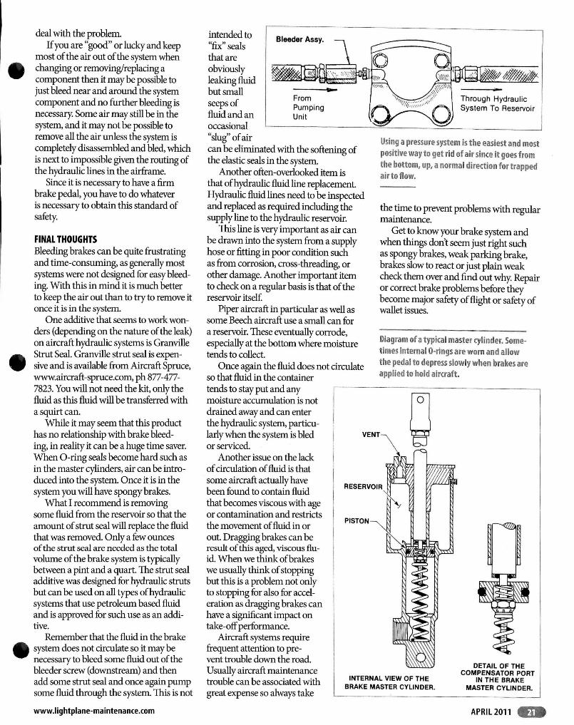
intended to "fix" seals that are obviously leaking fluid but small seeps of fluid and an occasional "slug" of air
From Pumping Unit
can be eliminated with the softening of the elastic seals in the system.
Another often-overlooked item is that of hydraulic fluid line replacement. Hydraulic fluid lines need to be inspected and replaced as required including the supply line to the hydraulic reservoir.
This line is very important as air can be drawn into the system from a supply hose or fitting in poor condition such as from corrosion, cross-threading, or other damage. Another important item to check on a regular basis is that of the reservoir itself.
Piper aircraft in particular as well as some Beech aircraft use a small can for a reservoir. These eventually corrode, especially at the bottom where moisture tends to collect.
Once again the fluid does not circulate so that fluid in the container tends to stay put and any moisture accumulation is not drained away and can enter the hydraulic system, particularly when the system is bled or serviced.
Another issue on the lack of circulation of fluid is that some aircraft actually have been found to contain fluid that becomes viscous with age or contamination and restricts the movement of fluid in or out. Dragging brakes can be result of this aged, viscous fluid. When we think ofbrakes we usually think of stopping but this is a problem not only to stopping for also for acceleration as dragging brakes can have a significant impact on take-off performance.
Aircraft systems require frequent attention to pre-
Through Hydraulic System To Reservoir
Using a pressure system is the easiest and most positive way to get rid of air since it goes from the bottom, up, a normal direction for trapped air to flow.
the time to prevent problems with regular maintenance.
Get to know your brake system and when things don't seem just right such as spongy brakes, weak parking brake, brakes slow to react or just plain weak check them over and find out why. Repair or correct brake problems before they become major safety of flight or safety of wallet issues.
Diagram of a typical master cylinder. Sometimes internal O-rings are worn and allow the pedal to depress slowly when brakes are applied to hold aircraft.
vent trouble down the road Usually aircraft maintenance trouble can be associated with great expense so always take
INTERNAL VIEW OF THE BRAKE MASTER CYLINDER.
DETAIL OF THE COMPENSATOR PORT
IN THE BRAKE MASTER CYLINDER.
.. --- --.. -.. ~.----.----.---.---.------- .. ----
APRIL2011 ..